JP4350289B2 - Sheet processing apparatus and image forming apparatus - Google Patents
Sheet processing apparatus and image forming apparatus Download PDFInfo
- Publication number
- JP4350289B2 JP4350289B2 JP2000299724A JP2000299724A JP4350289B2 JP 4350289 B2 JP4350289 B2 JP 4350289B2 JP 2000299724 A JP2000299724 A JP 2000299724A JP 2000299724 A JP2000299724 A JP 2000299724A JP 4350289 B2 JP4350289 B2 JP 4350289B2
- Authority
- JP
- Japan
- Prior art keywords
- needle
- sheet
- sheets
- cartridge
- binding
- Prior art date
- Legal status (The legal status is an assumption and is not a legal conclusion. Google has not performed a legal analysis and makes no representation as to the accuracy of the status listed.)
- Expired - Fee Related
Links
Images


Landscapes
- Folding Of Thin Sheet-Like Materials, Special Discharging Devices, And Others (AREA)
Description
【0001】
【発明の属する技術分野】
本発明は、シートを収納し収納されたシート束に対しシート綴じ装置による綴じ処理を行うシート処理装置並びに画像形成装置に関する。
【0002】
【従来の技術】
従来から自動的にシート束に綴じ処理を行う綴じ装置には、ある長さの一種類の針が準備されている。このため、シート束が厚い場合には針が貫通せず、綴じ処理が不完全になるため、綴じ可能許容枚数が設定されている。この許容枚数を超えた厚さのシート束の場合は綴じが禁止され、未綴じ処理に変更される。
【0003】
また、従来、シート綴じ装置(以下「ステイプラ」という)として、実公平3-25931号のように、着脱可能なカートリッジに連結された針シートを複数枚収納し、シート綴じ装置本体の針打ち込み部に搬送された針シートを一本ずつシート束へ打ち込み綴じ処理を行うものがある。このステイプラは多数枚のシート束に対して綴じ処理を行う場合に備えて針長さを所定値にし、少数枚の束に対してシート束裏側の針突出量が増加した場合、見栄え上の不具合を解消するため、余剰分の針を切断する切断機構を備えている。
【0004】
シート処理装置としては、ステイプルソータやフィニッシャーとして多数考案されている(特開平8-268640号)。前記、実公平3-25931号で考案されているシート綴じ装置を備えたフィニッシャーが考案されている。ここで、これらの切断針に関して図21を参照して説明する。
【0005】
ステイプラ500の先端部には、シュータ500bが配されており、後処理装置内の切断針ホッパー500cに対して、ステイプラが所定位置にて切断針を受け渡すような構成になっている。
【0006】
具体的には、シュータ500bの開閉部500dがニードルガイド500fの突起部500eに当接し、開閉部500dが開放状態になり、ガイド500fの斜面500gを経由してホッパー500c内に収納される。
【0007】
【発明が解決しようとする課題】
しかしながら、前記従来例においては、下記のような課題があった。
【0008】
(1)一種類の針しか準備されていないもので、許容枚数が限られてしまう。
【0009】
(2)切断した針の収納部がシート綴じ装置外に必要であり、シート綴じ装置との切断針の受渡しを円滑に行うためには、シート綴じ装置を平行に移動させる必要が生じ、シート束に対して斜めに綴じ処理を実行することが不可能である。
【0010】
(3)シート綴じ装置を使用する際のシート束枚数に関して、使用頻度が高いのは少数枚であり、多数枚の束に対して綴じ動作を行うことは希であるので、通常は必ず切断針が発生してしまい、エコロジー的に不具合がある。
【0011】
(4)切断針収納部に関して、ユーザーによる針除去作業が必要で煩わしいとともに、収納状態の検知(満タン検知等)が必要でめり、コストアップ、装置の大型化につながってしまう。
【0012】
本発明は上記課題に鑑みてなされたものであり、その目的は、切断針を発生させることなく、シート束の枚数に拘わらず綴じ処理可能なシート綴じ装置を備えたシート処理装置並びに画像形成装置を提供するものである。
【0013】
【課題を解決するための手段】
上記目的を達成するための本発明に係る代表的な構成は、シート束に対して針を打ち込む打ち込み部を備えたシート綴じ装置本体と、前記綴じ装置本体に対して着脱自在で、針を収納する針収納部を備えた針カートリッジとを有するシート綴じ装置を備えたシート処理装置において、前記針カートリッジは複数の針長さの針シートに対し複数種にて対応し、複数種の針カートリッジ各々の針シート収納部は綴じ装置本体に装着時に針長さ方向中心が略同一になるよう針を規制するガイド部と、前記複数種の針カートリッジの各々を前記綴じ装置本体に装着時に各々の針カートリッジを識別するカートリッジ識別手段と、シート収納部へのシート積載枚数を指定する枚数指定手段と、カートリッジ識別手段からの識別信号、及び枚数指定手段によるシート積載枚数に応じて、綴じ処理の実行を判断する綴じ処理判断部と、を有し、シート積載枚数が綴じ許容枚数内であれば、綴じ処理を行い、シート積載枚数が綴じ許容枚数以外であれば、装置を停止して針カートリッジ交換を促し、針カートリッジの交換後、シート積載枚数が綴じ許容枚数内であれば針の頭出しを行い、次のシート束の処理を開始することを特徴とする。
【0014】
上記構成にあっては、シート綴じ装置内の打ち込み部を針長さに拘わらず、共通にすることが可能になり、切断針の発生しない少数枚/多数枚にて綴じ処理可能である。
【0015】
また、針カートリッジが複数の針長さの針に対し複数種にて対応し、綴じ装置本体に装着時、各々の針カートリッジを識別するカートリッジ識別手段を設けることにより、針長さに応じた綴じ処理可能枚数以上、又は可能枚数外のシート束に対し、誤ってシート綴じ動作を実行してしまうようなことがなくなり、シート処理装置の信頼性を損なうこと無く、少数枚/多数枚にて綴じ処理が可能となる。
【0016】
【発明の実施の形態】
図1は、本発明を適用したステイプラシステムである。ステイプラS及び針シート100枚まで許容できる針カートリッジA、針シート60枚まで許容できる針カートリッジB、針シート20枚まで許容できる針カートリッジCより構成されており、針カートリッジA、B、Cは各々長さの異なる針がカートリッジ枠体aに対して、リフィールケースbを介して装填されている。
【0017】
針カートリッジの針長さは、図2にて示すとおり、最大許容束枚数に対応すべく、
【0018】
針カートリッジA=クラウン長さ(13mm)+(束厚み(10mm)+折り返し長さ(3mm))×2=39mm
【0019】
針カートリッジB=クラウン長さ(13mm)+(束厚み(6mm)+折り返し長さ(3mm))×2=31mm
【0020】
針カートリッジC=クラウン長さ(13mm)+(束厚み(2mm)+折り返し長さ(3mm))×2=23mm
【0021】
に設定されている。
【0022】
図3(a)は、カートリッジBの底面図を示しているが、カートリッジ枠体aにリフィールケースbを規制するリブc、及びリフィールケースbから出た針シートを規制するガイド部dが設けられており、ガイド部dは針シート搬送位置を規制している。
【0023】
同様に、図3(b)は図3(a)の矢印方向から見た各針カートリッジを示しており、ガイド部dにより針長さ方向中心が略同一になるように針シートを規制している。
【0024】
また、図3(a)に示した突起e、fは、針カートリッジを識別する識別手段としての突起であり、図3(b)に示すとおり、各カートリッジにより異なる配列に設定されている。本実施形態の場合、3種類の針カートリッジと、針カートリッジ無し状態を検出できるよう、ステイプラ本体側に2つのスイッチSW1,SW2(図9参照)が突起e、fに対応する位置に配されており、2つの出力信号により針カートリッジ状態を出力する。詳細を図4の検出状態テーブルに示す。
【0025】
次に上記ステイプラシステムを備えたシート処理装置に関して説明する。
【0026】
図5において、1はフィニッシャー、300は画像形成装置本体である。また、301,302はカセット、303,304は給送ローラ、305はレジストローラ、306は感光体ドラム、307は定着ローラである。画像形成装置本体300とRDFの詳細の説明については、ここでは省略する。399は画像形成装置本体の排出ローラ、2はフィニッシャー1の入口ローラ対、3は搬送ローラ、31は紙検知センサ、50は搬送されてきた紙の後端付近に穴あけをするパンチユニット、5は搬送大ローラで12、13、14の押下コロで紙を押圧し搬送する。
【0027】
11は切換フラッパでノンソートパス21とソートパス22を切りかえる。10は切換フラッパでソートパス22と紙を一時たくわえるためのバッファパス23の切り換えをおこなう。6は搬送ローラ、130はシートを一時的に集積し、整合、ステイプルを行なうための中間トレイ(以下処理トレイ)、7は処理トレイ(第1の積載トレイ)130上にシートを排出するための排出ローラ、150は揺動ガイド、180bは揺動ガイド150に支持され、揺動ガイド150の閉位置にきたときに、処理トレイ130に配置されたローラ(移送手段)180aと協働して処理トレイ130上のシートを束搬送してスタックトレイ(第2の積載トレイ)200上に束排出するための束排出ローラ(移送手段)である。
【0028】
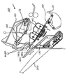
次に、ステイプラユニット100についての説明を図6(主断面)、図7(図6のa視図)、図8(図6のb視図)、図9を用いて行なう。
【0029】
ステイプラ(綴じ手段)101は、ホルダー102を介して移動台103に固定されている。移動台103に固定された軸104,105には、それぞれコロ106,107が回転自在に組み付けられ、該コロ106,107は固定台108に開設された穴状のレール(108a,108b,108c)に嵌合している。
【0030】
コロ106,107は、共に固定台108のレール穴より大きなフランジ106a,107aを有し、一方、移動台103の下方には、3ケ所に支持コロ、が配設されており、ステイプラ101を支持した移動台103は外れる事なくレールに沿って固定台108上を移動可能になっている。移動台103は、これに回転自在に設けられたコロ109により、固定台108上を移動する。
【0031】
前記レール穴(108a,108b,108c)は、前部と奥部においては、途中から分岐されて行き平行な2本のレールとなる。該レール形状により、ステイプラ101が手前に位置する時には、コロ106がレール穴108b側に、コロ107がレール穴108a側にそれぞれ嵌合されて傾いた状態となる。そして、ステイプラ101が中央部に位置する時には、コロ106、107共にレール穴108aに嵌合されて水平状態となる。
【0032】
更に、ステイプラ101が奥側に位置する時には、コロ106がレール穴108a側にコロ107がレール穴108c側に嵌合され手前の時とは逆の傾いた状態となる。
【0033】
なお、2つのコロ106、107が平行な2本のレールに各々嵌合された後は、その姿勢を保って移動する。そして、向き変え開始の作用は、不図示のカムによりなされる。
【0034】
次に、ステイプラ101の移動機構について説明する。
【0035】
前記移動台103の一方のコロ106は、ピニオンギア106b、ベルトプーリ106cが一体で形成されており、該ピニオンギアはプーリ106cにかけられたベルトを介して移動台上方から固定されたモータM100に連結されている。一方、固定台の下面には、レール穴に沿って前記ピニオンギア106bと嵌合する様にラックギア110が固定されており、前記モータM100の正逆回転で、移動台103は、ステイプラ101と共に前後へ移動される。
【0036】
また、移動台103の下面方向に延びる軸111には、ストッパ倒しコロ112が配設されている。これは、後述する処理トレイ130の後端ストッパ131とステイプラ101との衝突を回逃するために、後端ストッパ131を回動させる役割を担うものである。
【0037】
なお、ステイプラユニット100は、ステイプラ101のホームポジションを検知するセンサが設けられ、通常ステイプラ101はホームポジション(本実施の形態では最前部)にて待機している。
【0038】
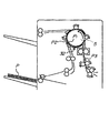
ここで、ステイプラユニット100に関して更に具体的に説明する。図9(a)はステイプラの主断面である。
【0039】
このステイプラユニット100はシート束に対して針を打ち込む打ち込み部を備えた本体と、該本体に対して着脱自在で、針を収納する針収納部と、前記本体の打ち込み部まで針を搬送するための針搬送支持部を備えた針カートリッジ100bとからなる。すなわち、ステイプラ本体100aに対して、針カートリッジ100bが装填されており、針が連結された針シートは、駆動源により矢印方向に回転駆動された送りローラ100cにより、図中左側へ搬送される。装置左側の針打ち込み部には矢印方向に独立に往復移動可能に支持されたフォーミングプレート100e、ドライバー100dが配されており、搬送された針シートを一本ずつフォーミング及び束への打ち込みを駆動源により行っている。また前述のように針カートリッジ100bの装填時に針カートリッジ100bの種類及び有無を検出する識別スイッチSW1,SW2、及びフォーミングされた針の有無検出を行うためのフォーミング針検知センサP10が本体100aに固定されている。
【0040】
図9(b)(c)は図9(a)の矢印C方向からのフォーミングプレート/ドライバーの作動状態を示したものであり、針長さによらずフォーミング/打ち込み動作が可能である。
【0041】
次に、処理トレイ130に積載されたシートPの後端を支持する後端ストッパ131について説明する。
【0042】
後端ストッパ131は、処理トレイ130の積載面に対して垂直面を有し、シート後端を支持する支持面131aと、処理トレイ130に設けられた丸穴に嵌合し揺動するためのピン131bと、後述するリンクと嵌合するためのピン131cを有している。リンクは、前記ステイプラ移動台130に組み付けられたコロ112が当接し押圧されるカム面132aを有した主リンク132と、主リンクの上端とに配設されたピン132bと後端ストッパのピン131cとをつなぐ連結リンク133とで構成される。
【0043】
なお、主リンク132は、図示しないフレームに固設されたシャフト134を支点として揺動するものである。また、主リンク132の下端は主リンクを時計方向に付勢する引張バネ135が設けられ、また、主リンクは、突き当て板により位置決めされているため、通常後端ストッパ131は処理トレイに対して垂直の姿勢を保つ。
【0044】
そして、ステイプル移動台103が移動すると、ステイプラ101と干渉関係になるストッパ131に連結された主リンク132のカム面を、移動台に設けられた倒しコロが押し倒す事となり、後端ストッパ131は連結リンク133で引っ張られ、ステイプラ101と干渉しない位置まで回動される。倒しコロ112は、ステイプラが移動している間、後端ストッパがこの回逃位置を保つ様に複数個(本構成においては3個)設けられている。
【0045】
そして、ステイプル101を支持するホルダー102の両側面には、後端ストッパ131と同一形状の支持面を持つステイプルストッパ113(2点鎖線)とが付設され、従って、ステイプラ101が水平状態(中央部)でストッパ131を押したままでも、ステイプルストッパ113でシート後端の支持が可能となる。
【0046】
次に、処理トレイユニット129について図10を参照して説明する。
【0047】
処理トレイユニット129は、画像形成装置本体300からのシートを搬送する搬送部と処理トレイ130で処理された束を受け取り収容するスタックトレイ200の中間に配設される。
【0048】
そして、処理トレイユニット129は、処理トレイ130、後端ストッパ131、整合手段140、揺動ガイド150、引き込みパドル160、出没トレイ170、束排出ローラ対180で構成されている。
【0049】
処理トレイ130は、下流側(図の左)を上方に上流側(図の右)を下方にした傾斜トレイであり、下方の端部には、前述の後端ストッパが嵌合されている。搬送部の排出ローラ対で排出されたシートPは、自重及び後述するパドル160の作用で、その後端が後端ストッパ131に当接するまで、処理トレイ130上を滑走する。
【0050】
また、処理トレイ130の上方端部には、束排出ローラ対180が、また、後述する揺動ガイド150には、それと当接する束排出上ローラ180bがそれぞれ付設され、モータM180からの駆動を受けて正逆転可能となっている。
【0051】
次に、シートPの流れについて説明する。
【0052】
ユーザーが、画像形成装置本体の操作部(図示略)で、ノンソートモードを指定したいとき、図11に示すように、入口ローラ対2、搬送ローラ3、搬送大ローラ5は回転し、画像形成装置本体300から搬送されてくるシートPを搬送する。切換フラッパ11は、図に示す位置にソレノイド(図示略)の働きにより回動し、シートPをノンソートパス21に搬送する。センサ33でシートPの後端を検知したら、ローラ9は、積載に適した速度で回転し、スタックトレイ200にシートPを排出する。
【0053】
次に、ユーザーがステイプルソートモードを指定したときの動作を説明する。
【0054】
図12に示すように、入口ローラ対2、搬送ローラ3、搬送大ローラ5は回転し、画像形成装置本体300から搬送されていくるシートPを搬送する。フラッパ10,11は、図の位置で停止している。シートPは、ソートパス22通り、排出ローラ7によりステイプラ101に排出される。このとき、出没トレイ170は、突出位置にあるため、排出ローラ7でシートPを排出した先に、先端垂れ下がり、戻り不良になるのを防止すると共に、処理トレイ上のシートの整列性を高めている。
【0055】
排出されたシートPは、自重で後端ストッパ131へ移動し始め、加えてホームポジション停止していたパドル160は、モータM160の駆動を受けて反時計方向に回動し、前記シートの移動を助長する。シートPの後端が、ストッパ131に確実に当接し停止するときと、パドル160の回転も停止され、整合部材が排出されたシートを整合する。
【0056】
1部目のシートが全て処理トレイ130上に排出され、整合されたら、図13に示すように、揺動ガイド150は降りてきて、束排出上ローラ180bがシート束の上に乗り、ステイプラ101は、シート束をステイプルする。
【0057】
一方、その間に、画像形成装置本体300から排出されてきたシートP1は、図13に示すように、フラッパ10の回動により搬送大ローラ5に巻き付けられ、センサ32から所定距離進んだところで停止する。次のシートP2が紙検知センサー31から所定距離進んだら、図14に示すように、搬送大ローラ5は回転し、1枚目のシートP1より2枚目のシートP2の方が所定距離先行するように重ね合わせ、図15に示すように、搬送大ローラ5に巻き付け、所定距離で停止する。一方、処理トレイ130上のシート束は、図15に示すように、スタックトレイ200上に束排出される。
【0058】
但し、この時、出没トレイ170は、シート束をスタックトレイ200に落下させるために、シート束が束排紙ローラを抜ける前に、ホームポジションへ移動する。図16に示すように、3枚目のシートP3が所定位に到達したら、搬送大ローラ5は回転し、シートP3を所定距離ずらして重ね合わせ、フラッパ10は回動して3枚のシートPをソートパス22に搬送する。
【0059】
図17(a)に示すように、揺動ガイド150は降りたまま、ローラ180a,180bで3枚のシートPを受け取り、図17(b)に示すように、シートPの後端がローラ7を抜けたらローラ180a,180bは逆転し、後端がストッパ131に当接する前に、図17(c)に示すように、揺動ガイド150は上昇し、ローラ180bはシート面から離れる。4枚目以降のシートPは、1部目の動作と同様ソートパスを通って、処理トレイ上に排出される。3部目以降は、2部目と同じ動作をし、設定部数分スタックトレイ200に積載し終了する。
【0060】
上記複数枚のシートを重ね搬送において、各シートPは搬送方向にオフセットされており、シートP2はシートP1に対し下流にオフセットし、シートP3はシートP2に対し下流にオフセットされている。
【0061】
シートPのオフセット量と揺動ガイド上昇タイミングは、束排出ローラの戻し速度によるシートの静定時間に関り、すなわち、画像形成装置本体300の処理能力によって決まり、本実施の形態においては、シートの搬送速度750mm/s、オフセット量(b=20mm)位、束排出ローラ戻し速度500mm/sにおいて、束排出ローラの離間位置は、シートP1がストッパに当接する40mm(aの値)手前に到達したタイミングに設定している。
【0062】
ここで、前述の針カートリッジ識別信号に基づいた動作に関して図4の検出状態テーブル、及び図18のステイプルソートモードフローチャートに基づいて説明する。
【0063】
前述の処理トレイ130上への排出動作中において、処理トレイ130へのシート排出と同時に枚数カウント手段としての処理トレイ積載枚数カウンタを起動して積載枚数をカウントする。そして、束ラスト紙排出完了と同時にカウンタを停止し、処理判断部において針カートリッジ識別信号に応じて「検出状態テーブル」より算出した(綴じ許容枚数)と(積載枚数)を比較する。
【0064】
尚、シート積載枚数は予め原稿枚数をカウントして指示してもよいし、マニュアルでシート積載枚数を入力してもよい。
【0065】
そして、(綴じ許容枚数)≧(積載枚数)の場合は、そのままステイプル処理を行う。しかし、(綴じ許容枚数)<(積載枚数)の場合は、ステイプル処理を行わず、未綴じのまま束排出を行い、画像形成装置側へ「アラーム」信号を発信すると同時に動作を終了し、待機状態に移行する。
【0066】
画像形成装置のディスプレイにて「積載枚数が超過している」旨のメッセージを発信し、針カートリッジの交換を促す。
【0067】
新たな針カートリッジが装填された場合、前述のフォーミング針検知センサによる信号に基づき、針頭出し動作(針検知するまでの空打ち動作)を実行した後、積載枚数が許容枚数以内の針カートリッジの場合、自動的にスタートしてリカバリー動作(残り部数のステイプル処理を行う)に移行する。
【0068】
〔他の実施形態〕
ここで、前述の針カートリッジ識別信号に基づいた動作に関して図19の検出状態テーブル、及び図20のステイプルソートモードフローチャートに基づいて説明する。
【0069】
前述の処理トレイ130上への排出動作中において、処理トレイ130へのシート排出と同時に枚数カウント手段としての処理トレイ積載枚数カウンタを起動して積載枚数をカウントする。そして、束ラスト紙排出完了と同時にカウンタを停止し、処理判断部において針カートリッジ識別信号に応じて「検出状態テーブル」より算出した(綴じ許容枚数)と(積載枚数)を比較する。
【0070】
尚、シート積載枚数は予め原稿枚数をカウントして指示してもよいし、マニュアルでシート積載枚数を入力してもよい。
【0071】
そして、(最大綴じ許容枚数)≧(積載枚数)≧(最小綴じ許容枚数)の場合は、そのままステイプル処理を行う。しかし、(最大綴じ許容枚数)<(積載枚数)、又は(積載枚数)<(最小綴じ許容枚数)の場合は、ステイプル処理を行わず、未綴じのまま束排出を行い、画像形成装置側へ「アラーム」信号を発信すると同時に動作を終了し、待機状態に移行する。
【0072】
画像形成装置のディスプレイにて「積載枚数が少ない若しくは超過している」旨のメッセージを発信し、針カートリッジの交換を促す。
【0073】
新たな針カートリッジが装填された場合、前述のフォーミング針検知センサによる信号に基づき、針頭出し動作(針検知するまでの空打ち動作)を実行した後、積載枚数が許容枚数以内の針カートリッジの場合、自動的にスタートしてリカバリー動作(残り部数のステイプル処理を行う)に移行する。
【0074】
【発明の効果】
以上説明したように、本発明によれば、切断針レスの少数枚/多数枚に対応したシート綴じ装置が提供できる。このため、シート綴じ装置内に針カッター等の機構が不要になりコスト低減が可能になるとともに、製品クズを出さないエコロジーな商品の提供が出来る。
【0075】
また、シート処理装置にシート綴じ装置を装着した際、各カートリッジの識別手段を設けることにより、許容束厚以上又は以外での綴じ処理動作を未然に防止することが出来、シート処理装置としての信頼性を維持できるとともに、切断針の収納部及び切断針収納状態を検出する検出手段等が不要になり、コスト低減、装置の小型化等が可能になる。
【図面の簡単な説明】
【図1】 本実施形のシート綴じ装置の斜視説明図である。
【図2】 針長さの説明図である。
【図3】 (a)は針カートリッジ底面図、(b)は各針カートリッジ搬送状態図である。
【図4】 識別信号に基づくカートリッジ状態/許容束枚数の検出状態テーブルである。
【図5】 本発明のシート処理装置の全体構成を示す正面図である。
【図6】 ステイプラと処理トレイ部の側面図である。
【図7】 図6のa視図でステイプラ移動機構の平面図である。
【図8】 図6のb視図でステイプラの背面図である。
【図9】 (a)はステイプラ主断面図、(b)(c)は(a)の矢印方向図である。
【図10】 揺動ガイドと処理トレイの縦断側面図である。
【図11】 ノンソートモード時のシート処理装置の動作図である。
【図12】 ステイプルソートモード時のシート処理装置の動作図である。
【図13】 ステイプルソートモード時のシート処理装置の動作図である。
【図14】 ステイプルソートモード時のシート処理装置の動作図である。
【図15】 ステイプルソートモード時のシート処理装置の動作図である。
【図16】 ステイプルソートモード時のシート処理装置の動作図である。
【図17】 ステイプルソートモード時のシート処理装置の動作図である。
【図18】 ステイプルソートモード時の動作フローチャートである。
【図19】 他の実施形態を示す、識別信号に基づくカートリッジ状態/許容束枚数の検出状態テーブルである。
【図20】 上記他の実施形態のステイプルソートモード時の動作フローチャートである。
【図21】 従来例の補足図である。[0001]
BACKGROUND OF THE INVENTION
The present invention relates to a sheet processing apparatus and an image forming apparatus that store sheets and perform binding processing by a sheet binding apparatus on a stored sheet bundle.
[0002]
[Prior art]
Conventionally, one type of needle having a certain length is prepared in a binding apparatus that automatically performs binding processing on a sheet bundle. For this reason, when the sheet bundle is thick, the needle does not penetrate and the binding process becomes incomplete, so the allowable number of sheets that can be bound is set. In the case of a sheet bundle having a thickness exceeding the allowable number of sheets, binding is prohibited and changed to unbinding processing.
[0003]
Conventionally, as a sheet binding device (hereinafter referred to as “stapler”), a plurality of needle sheets connected to a detachable cartridge are stored as in Japanese Utility Model No. 3-25931, and a needle driving portion of the sheet binding device main body is stored. There are some which perform the binding process by driving the needle sheets conveyed to the sheet bundle one by one into the sheet bundle. This stapler has a needle length that is set to a predetermined value in preparation for performing binding processing on a large number of sheet bundles. In order to solve this problem, a cutting mechanism for cutting excess needles is provided.
[0004]
Many sheet processing apparatuses have been devised as staple sorters and finishers (Japanese Patent Laid-Open No. 8-268640). A finisher having a sheet binding device devised in Japanese Utility Model Publication No. 3-25931 has been devised. Here, these cutting needles will be described with reference to FIG.
[0005]
A
[0006]
Specifically, the opening /
[0007]
[Problems to be solved by the invention]
However, the conventional example has the following problems.
[0008]
(1) Since only one type of needle is prepared, the allowable number of sheets is limited.
[0009]
(2) A storage unit for the cut needle is required outside the sheet binding device, and in order to smoothly transfer the cutting needle to and from the sheet binding device, it is necessary to move the sheet binding device in parallel. It is impossible to execute the binding process diagonally.
[0010]
(3) With regard to the number of sheet bundles when using the sheet binding apparatus, a small number of sheets are frequently used, and it is rare to perform a binding operation on a bundle of many sheets. Has occurred and is ecologically defective.
[0011]
(4) Regarding the cutting needle storage unit, the user needs to remove the needle, which is troublesome and requires detection of the storage state (full tank detection, etc.), leading to an increase in cost and the size of the apparatus.
[0012]
The present invention has been made in view of the above problems, and an object of the present invention is to provide a sheet processing apparatus and an image forming apparatus provided with a sheet binding apparatus capable of performing binding processing regardless of the number of sheet bundles without generating a cutting needle. Is to provide.
[0013]
[Means for Solving the Problems]
In order to achieve the above object, a typical configuration according to the present invention includes a sheet binding device main body having a driving portion for driving a needle into a sheet bundle, and is detachable from the binding device main body and stores the needle. In a sheet processing apparatus having a sheet binding device having a needle cartridge having a needle storage section, the needle cartridge corresponds to a plurality of types of needle sheets having a plurality of needle lengths, and each of the plurality of types of needle cartridges The needle sheet storage portion includes a guide portion for restricting the needle so that the center in the needle length direction is substantially the same when the staple sheet is mounted on the binding device body, and each of the plurality of types of needle cartridges when the staple device body is mounted on the staple device body. Cartridge identification means for identifying the cartridge, number designation means for designating the number of sheets stacked in the sheet storage unit, identification signal from the cartridge identification means, and number designation means A binding process determination unit that determines whether to execute the binding process according to the number of sheets stacked, and performs the binding process if the number of stacked sheets is within the allowable binding number. If this is the case, the apparatus is stopped to prompt the user to replace the staple cartridge, and after replacing the staple cartridge, if the number of stacked sheets is within the allowable number of sheets, the head of the staple is cued and processing of the next sheet bundle is started. Features .
[0014]
In the above configuration, the driving unit in the sheet binding apparatus can be made common regardless of the needle length, and the binding process can be performed with a small number / a large number of sheets in which cutting needles are not generated.
[0015]
In addition, the needle cartridge can handle a plurality of types of needles having a plurality of needle lengths, and when the cartridge is attached to the binding apparatus main body, a cartridge identification unit for identifying each needle cartridge is provided, so that the binding corresponding to the needle length is provided. A sheet binding operation is not erroneously performed on a sheet bundle that is greater than or equal to the number of sheets that can be processed, and a small number of sheets / multiple sheets are bound without impairing the reliability of the sheet processing apparatus. Processing is possible.
[0016]
DETAILED DESCRIPTION OF THE INVENTION
FIG. 1 shows a stapler system to which the present invention is applied. The stapler S and the needle cartridge A that can accept up to 100 needle sheets, the needle cartridge B that can accept up to 60 needle sheets, and the needle cartridge C that can accept up to 20 needle sheets are composed of the needle cartridges A, B, and C. Needles having different lengths are loaded into the cartridge frame a through the refill case b.
[0017]
As shown in FIG. 2, the needle length of the needle cartridge is set to correspond to the maximum allowable number of bundles.
[0018]
Needle cartridge A = crown length (13mm) + (bundle thickness (10mm) + folding length (3mm)) x 2 = 39mm
[0019]
Needle cartridge B = crown length (13mm) + (bundle thickness (6mm) + folding length (3mm)) x 2 = 31mm
[0020]
Needle cartridge C = crown length (13mm) + (bundle thickness (2mm) + folding length (3mm)) x 2 = 23mm
[0021]
Is set to
[0022]
FIG. 3A shows a bottom view of the cartridge B. The cartridge frame a is provided with a rib c for restricting the refill case b and a guide portion d for restricting the needle sheet protruding from the refill case b. The guide portion d regulates the needle sheet conveyance position.
[0023]
Similarly, FIG. 3B shows each needle cartridge as viewed from the direction of the arrow in FIG. 3A, and the needle seat is regulated by the guide portion d so that the centers in the needle length direction are substantially the same. Yes.
[0024]
Also, the protrusions e and f shown in FIG. 3A are protrusions as identification means for identifying the needle cartridge, and are set in different arrangements for each cartridge as shown in FIG. 3B. In the case of this embodiment, two switches SW1 and SW2 (see FIG. 9) are arranged on the stapler main body side at positions corresponding to the protrusions e and f so that the three types of needle cartridges and the state of no needle cartridge can be detected. The needle cartridge state is output by two output signals. Details are shown in the detection state table of FIG.
[0025]
Next, a sheet processing apparatus provided with the above stapler system will be described.
[0026]
In FIG. 5, 1 is a finisher, and 300 is an image forming apparatus main body. Further, 301 and 302 are cassettes, 303 and 304 are feeding rollers, 305 is a registration roller, 306 is a photosensitive drum, and 307 is a fixing roller. A detailed description of the image forming apparatus
[0027]
11 is a switching flapper that switches between the
[0028]
Next, the
[0029]
A stapler (binding means) 101 is fixed to the moving table 103 via a
[0030]
The
[0031]
The rail holes (108a, 108b, 108c) are branched from the middle at the front and back portions to become two parallel rails. Due to the rail shape, when the
[0032]
Further, when the
[0033]
In addition, after the two
[0034]
Next, the moving mechanism of the
[0035]
One
[0036]
Further, a
[0037]
The
[0038]
Here, the
[0039]
The
[0040]
FIGS. 9 (b) and 9 (c) show the operating state of the forming plate / driver from the direction of arrow C in FIG. 9 (a), and the forming / driving operation is possible regardless of the needle length.
[0041]
Next, the trailing
[0042]
The
[0043]
The
[0044]
When the staple moving table 103 is moved, the cam surface of the
[0045]
A staple stopper 113 (two-dot chain line) having a support surface having the same shape as that of the
[0046]
Next, the
[0047]
The
[0048]
The
[0049]
The
[0050]
In addition, a bundle
[0051]
Next, the flow of the sheet P will be described.
[0052]
When the user wants to specify the non-sort mode in the operation unit (not shown) of the image forming apparatus main body, as shown in FIG. The sheet P conveyed from the apparatus
[0053]
Next, the operation when the user designates the staple sort mode will be described.
[0054]
As shown in FIG. 12, the
[0055]
The discharged sheet P begins to move to the trailing
[0056]
When all the first sheets are discharged onto the
[0057]
On the other hand, as shown in FIG. 13, the sheet P1 discharged from the image forming apparatus
[0058]
However, at this time, the in / out
[0059]
As shown in FIG. 17A, three sheets P are received by the
[0060]
In the stacked conveyance of the plurality of sheets, each sheet P is offset in the conveyance direction, the sheet P2 is offset downstream with respect to the sheet P1, and the sheet P3 is offset downstream with respect to the sheet P2.
[0061]
The offset amount of the sheet P and the swing guide raising timing are related to the sheet stabilization time depending on the return speed of the bundle discharge roller, that is, the processing capacity of the image forming apparatus
[0062]
Here, the operation based on the above-described needle cartridge identification signal will be described with reference to the detection state table of FIG. 4 and the staple sort mode flowchart of FIG.
[0063]
During the discharge operation onto the
[0064]
Note that the number of stacked sheets may be specified by counting the number of documents in advance, or the number of stacked sheets may be input manually.
[0065]
If (binding allowable number) ≧ (stacked number), stapling is performed as it is. However, if (the allowable number of bindings) <(the number of stacked sheets), the stapling process is not performed, the bundle is discharged without binding, the operation is terminated at the same time as sending the “alarm” signal to the image forming apparatus side, and waiting. Transition to the state.
[0066]
A message stating that “the number of loaded sheets has been exceeded” is transmitted on the display of the image forming apparatus, and prompts the user to replace the needle cartridge.
[0067]
When a new staple cartridge is loaded, after executing the needle cueing operation (empty punching operation until the needle is detected) based on the signal from the forming needle detection sensor, the number of loaded cartridges is within the allowable number. Then, it automatically starts and shifts to a recovery operation (performing stapling of the remaining number of copies).
[0068]
[Other Embodiments]
Here, the operation based on the above-described needle cartridge identification signal will be described based on the detection state table in FIG. 19 and the staple sort mode flowchart in FIG.
[0069]
During the discharge operation onto the
[0070]
Note that the number of stacked sheets may be specified by counting the number of documents in advance, or the number of stacked sheets may be input manually.
[0071]
If (maximum binding allowable number) ≧ (stacked number) ≧ (minimum binding allowable number), the stapling process is performed as it is. However, if (maximum binding allowable number) <(stacking number) or (stacking number) <(minimum binding allowable number), stapling is not performed, the bundle is discharged without binding, and the image forming apparatus is moved to the image forming apparatus side. At the same time as the “alarm” signal is transmitted, the operation is terminated and a transition is made to a standby state.
[0072]
A message stating that “the number of sheets to be loaded is too small or excessive” is transmitted on the display of the image forming apparatus, and prompts the user to replace the needle cartridge.
[0073]
When a new staple cartridge is loaded, after executing the needle cueing operation (empty punching operation until the needle is detected) based on the signal from the forming needle detection sensor, the number of loaded cartridges is within the allowable number. Then, it automatically starts and shifts to a recovery operation (performing stapling of the remaining number of copies).
[0074]
【The invention's effect】
As described above, according to the present invention, it is possible to provide a sheet binding device corresponding to a small number / a large number of cutting needles. This eliminates the need for a mechanism such as a needle cutter in the sheet binding apparatus, enables cost reduction, and provides ecological products that do not cause product waste.
[0075]
In addition, when the sheet binding apparatus is mounted on the sheet processing apparatus, by providing an identification means for each cartridge, it is possible to prevent the binding processing operation at or above the allowable bundle thickness, and the reliability as the sheet processing apparatus. Therefore, it is possible to reduce the cost and the size of the apparatus.
[Brief description of the drawings]
FIG. 1 is an explanatory perspective view of a sheet binding apparatus according to an embodiment.
FIG. 2 is an explanatory diagram of a needle length.
FIG. 3A is a bottom view of a needle cartridge, and FIG. 3B is a state of conveyance of each needle cartridge.
FIG. 4 is a cartridge state / allowable bundle number detection state table based on an identification signal.
FIG. 5 is a front view showing the overall configuration of the sheet processing apparatus of the present invention.
FIG. 6 is a side view of a stapler and a processing tray unit.
7 is a plan view of a stapler moving mechanism as seen from a in FIG.
FIG. 8 is a rear view of the stapler as viewed from b in FIG. 6;
9A is a main cross-sectional view of a stapler, and FIGS. 9B and 9C are arrow direction views of FIG.
FIG. 10 is a vertical side view of a swing guide and a processing tray.
FIG. 11 is an operation diagram of the sheet processing apparatus in a non-sort mode.
FIG. 12 is an operation diagram of the sheet processing apparatus in a staple sort mode.
FIG. 13 is an operation diagram of the sheet processing apparatus in a staple sort mode.
FIG. 14 is an operation diagram of the sheet processing apparatus in a staple sort mode.
FIG. 15 is an operation diagram of the sheet processing apparatus in a staple sort mode.
FIG. 16 is an operation diagram of the sheet processing apparatus in a staple sort mode.
FIG. 17 is an operation diagram of the sheet processing apparatus in a staple sort mode.
FIG. 18 is an operation flowchart in a staple sort mode.
FIG. 19 is a detection state table of cartridge state / allowable bundle number based on an identification signal according to another embodiment.
FIG. 20 is an operation flowchart in a staple sort mode according to another embodiment.
FIG. 21 is a supplementary diagram of a conventional example.
Claims (2)
前記針カートリッジは複数の針長さの針シートに対し複数種にて対応し、複数種の針カートリッジ各々の針シート収納部は綴じ装置本体に装着時に針長さ方向中心が略同一になるよう針を規制するガイド部と、
前記複数種の針カートリッジの各々を前記綴じ装置本体に装着時に各々の針カートリッジを識別するカートリッジ識別手段と、
シート収納部へのシート積載枚数を指定する枚数指定手段と、
前記カートリッジ識別手段からの識別信号、及び前記枚数指定手段によるシート積載枚数に応じて、綴じ処理の実行を判断する綴じ処理判断部と、
を有し、
シート積載枚数が綴じ許容枚数内であれば、綴じ処理を行い、シート積載枚数が綴じ許容枚数以外であれば、装置を停止して針カートリッジ交換を促し、針カートリッジの交換後、シート積載枚数が綴じ許容枚数内であれば針の頭出しを行い、次のシート束の処理を開始することを特徴とするシート処理装置。 Comprising a sheet binding device body with a driving unit driving the needle against the sheet bundle, detachable from the binding device body, the sheet stapling device having a needle cartridge having a needle storage portion for accommodating the needle In the sheet processing apparatus ,
The needle cartridge corresponds to a plurality of types of needle sheets having a plurality of needle lengths, and the needle sheet storage portion of each of the plurality of types of needle cartridges has a substantially same center in the needle length direction when attached to the binding device body. A guide part for regulating the needle,
Cartridge identifying means for identifying each of the plurality of types of needle cartridges when the staple cartridge is mounted on the binding device body;
A sheet number designating unit for designating the number of sheets stacked in the sheet storage unit;
A binding process determination unit that determines the execution of the binding process according to the identification signal from the cartridge identification unit and the number of sheets stacked by the sheet number specifying unit;
Have
If the number of stacked sheets is within the allowable number of sheets, the binding process is performed. If the number of stacked sheets is other than the allowable number of sheets, the apparatus is stopped to prompt the user to replace the staple cartridge. A sheet processing apparatus characterized by cueing a needle and starting the processing of the next sheet bundle if the number is within the allowable number of sheets to be bound .
シートに画像形成する画像形成装置本体と、
請求項1記載のシート処理装置と、
を有することを特徴とする画像形成装置。 In an image forming apparatus including a sheet processing apparatus that performs a binding process on a sheet bundle,
An image forming apparatus main body for forming an image on a sheet;
A sheet processing apparatus according to claim 1;
An image forming apparatus comprising:
Priority Applications (1)
| Application Number | Priority Date | Filing Date | Title |
|---|---|---|---|
| JP2000299724A JP4350289B2 (en) | 1999-10-04 | 2000-09-29 | Sheet processing apparatus and image forming apparatus |
Applications Claiming Priority (3)
| Application Number | Priority Date | Filing Date | Title |
|---|---|---|---|
| JP11-282599 | 1999-10-04 | ||
| JP28259999 | 1999-10-04 | ||
| JP2000299724A JP4350289B2 (en) | 1999-10-04 | 2000-09-29 | Sheet processing apparatus and image forming apparatus |
Publications (3)
| Publication Number | Publication Date |
|---|---|
| JP2001171898A JP2001171898A (en) | 2001-06-26 |
| JP2001171898A5 JP2001171898A5 (en) | 2007-10-04 |
| JP4350289B2 true JP4350289B2 (en) | 2009-10-21 |
Family
ID=26554673
Family Applications (1)
| Application Number | Title | Priority Date | Filing Date |
|---|---|---|---|
| JP2000299724A Expired - Fee Related JP4350289B2 (en) | 1999-10-04 | 2000-09-29 | Sheet processing apparatus and image forming apparatus |
Country Status (1)
| Country | Link |
|---|---|
| JP (1) | JP4350289B2 (en) |
Families Citing this family (9)
| Publication number | Priority date | Publication date | Assignee | Title |
|---|---|---|---|---|
| JP4419335B2 (en) | 2001-03-12 | 2010-02-24 | マックス株式会社 | Staple cartridge system |
| JP4857504B2 (en) * | 2001-09-10 | 2012-01-18 | マックス株式会社 | Electric stapler staple detection mechanism |
| JP4071642B2 (en) | 2002-03-25 | 2008-04-02 | 株式会社リコー | Paper processing apparatus and image forming system |
| AU2003235271A1 (en) * | 2002-04-19 | 2003-11-03 | Max Co., Ltd. | Motor stapler |
| JP4328685B2 (en) | 2004-07-20 | 2009-09-09 | キヤノン株式会社 | Sheet processing device |
| US7396008B2 (en) * | 2004-07-22 | 2008-07-08 | Fuji Xerox Co., Ltd. | Stapling device |
| JP4423249B2 (en) * | 2005-08-30 | 2010-03-03 | キヤノン株式会社 | Sheet processing device |
| JP4949160B2 (en) | 2006-09-15 | 2012-06-06 | 株式会社リコー | Ring bind control device, ring bind control method, and ring bind control program |
| JP7334413B2 (en) * | 2019-01-23 | 2023-08-29 | コニカミノルタ株式会社 | Control device and judgment method |
-
2000
- 2000-09-29 JP JP2000299724A patent/JP4350289B2/en not_active Expired - Fee Related
Also Published As
| Publication number | Publication date |
|---|---|
| JP2001171898A (en) | 2001-06-26 |
Similar Documents
| Publication | Publication Date | Title |
|---|---|---|
| KR100444363B1 (en) | Sheet stapler unit and sheet processing device | |
| JP3740280B2 (en) | Sheet processing apparatus and image forming apparatus having the same | |
| US7472899B2 (en) | Sheet processing apparatus, image forming apparatus, control method, and program | |
| JP4350289B2 (en) | Sheet processing apparatus and image forming apparatus | |
| JP3559718B2 (en) | Sheet processing apparatus and image forming apparatus having the same | |
| JP3363725B2 (en) | Sheet punching device, sheet processing device, and image forming device | |
| US8002401B2 (en) | Sheet processing apparatus and image forming apparatus | |
| JPH10324449A (en) | Sheet processing device | |
| JP3728039B2 (en) | Sheet processing apparatus and image forming apparatus having the same | |
| JP3799124B2 (en) | Sheet post-processing apparatus and image forming apparatus | |
| JPH10194569A (en) | Sheet processor and image forming device provided therewith | |
| JP3542474B2 (en) | Sheet processing apparatus and image forming apparatus having the same | |
| JPH10181981A (en) | Sheet processor and image forming device provided therewith | |
| JP2009018933A (en) | Sheet processing device and image forming device | |
| JP2001334502A (en) | Shseet binding device, sheet treating device and image forming device | |
| JP2003261258A (en) | Paper processor and image forming system | |
| JPH11292387A (en) | Sheet post-processor | |
| JP2003043763A (en) | Sheet processing device and image forming apparatus provided with the same | |
| JP3653461B2 (en) | Post-processing device for image forming apparatus | |
| JP2000086074A (en) | Sheet after processing device | |
| JP2005349559A (en) | After-treatment device of image forming apparatus | |
| JPH07285726A (en) | Sheet after-treatment device | |
| JP2737372B2 (en) | Sheet distribution and storage device | |
| JPH08108378A (en) | Stapler and bookbinding device using it | |
| JPH10324452A (en) | Aligning mechanism and sheet post processing device provided with aligning mechanism |
Legal Events
| Date | Code | Title | Description |
|---|---|---|---|
| A521 | Written amendment |
Free format text: JAPANESE INTERMEDIATE CODE: A523 Effective date: 20070820 |
|
| A621 | Written request for application examination |
Free format text: JAPANESE INTERMEDIATE CODE: A621 Effective date: 20070820 |
|
| RD02 | Notification of acceptance of power of attorney |
Free format text: JAPANESE INTERMEDIATE CODE: A7422 Effective date: 20080116 |
|
| A977 | Report on retrieval |
Free format text: JAPANESE INTERMEDIATE CODE: A971007 Effective date: 20090417 |
|
| A131 | Notification of reasons for refusal |
Free format text: JAPANESE INTERMEDIATE CODE: A131 Effective date: 20090421 |
|
| A521 | Written amendment |
Free format text: JAPANESE INTERMEDIATE CODE: A523 Effective date: 20090622 |
|
| TRDD | Decision of grant or rejection written | ||
| A01 | Written decision to grant a patent or to grant a registration (utility model) |
Free format text: JAPANESE INTERMEDIATE CODE: A01 Effective date: 20090714 |
|
| A01 | Written decision to grant a patent or to grant a registration (utility model) |
Free format text: JAPANESE INTERMEDIATE CODE: A01 |
|
| A61 | First payment of annual fees (during grant procedure) |
Free format text: JAPANESE INTERMEDIATE CODE: A61 Effective date: 20090722 |
|
| FPAY | Renewal fee payment (event date is renewal date of database) |
Free format text: PAYMENT UNTIL: 20120731 Year of fee payment: 3 |
|
| R150 | Certificate of patent or registration of utility model |
Free format text: JAPANESE INTERMEDIATE CODE: R150 |
|
| FPAY | Renewal fee payment (event date is renewal date of database) |
Free format text: PAYMENT UNTIL: 20120731 Year of fee payment: 3 |
|
| FPAY | Renewal fee payment (event date is renewal date of database) |
Free format text: PAYMENT UNTIL: 20130731 Year of fee payment: 4 |
|
| LAPS | Cancellation because of no payment of annual fees |