JP4729269B2 - Laser scanning microscope - Google Patents
Laser scanning microscope Download PDFInfo
- Publication number
- JP4729269B2 JP4729269B2 JP2004163360A JP2004163360A JP4729269B2 JP 4729269 B2 JP4729269 B2 JP 4729269B2 JP 2004163360 A JP2004163360 A JP 2004163360A JP 2004163360 A JP2004163360 A JP 2004163360A JP 4729269 B2 JP4729269 B2 JP 4729269B2
- Authority
- JP
- Japan
- Prior art keywords
- laser
- laser light
- wavelength
- microscope
- deviation
- Prior art date
- Legal status (The legal status is an assumption and is not a legal conclusion. Google has not performed a legal analysis and makes no representation as to the accuracy of the status listed.)
- Active
Links
Images


Classifications
-
- G—PHYSICS
- G02—OPTICS
- G02B—OPTICAL ELEMENTS, SYSTEMS OR APPARATUS
- G02B26/00—Optical devices or arrangements for the control of light using movable or deformable optical elements
- G02B26/08—Optical devices or arrangements for the control of light using movable or deformable optical elements for controlling the direction of light
- G02B26/10—Scanning systems
- G02B26/101—Scanning systems with both horizontal and vertical deflecting means, e.g. raster or XY scanners
-
- G—PHYSICS
- G02—OPTICS
- G02B—OPTICAL ELEMENTS, SYSTEMS OR APPARATUS
- G02B21/00—Microscopes
- G02B21/0004—Microscopes specially adapted for specific applications
- G02B21/002—Scanning microscopes
-
- G—PHYSICS
- G02—OPTICS
- G02F—OPTICAL DEVICES OR ARRANGEMENTS FOR THE CONTROL OF LIGHT BY MODIFICATION OF THE OPTICAL PROPERTIES OF THE MEDIA OF THE ELEMENTS INVOLVED THEREIN; NON-LINEAR OPTICS; FREQUENCY-CHANGING OF LIGHT; OPTICAL LOGIC ELEMENTS; OPTICAL ANALOGUE/DIGITAL CONVERTERS
- G02F1/00—Devices or arrangements for the control of the intensity, colour, phase, polarisation or direction of light arriving from an independent light source, e.g. switching, gating or modulating; Non-linear optics
- G02F1/01—Devices or arrangements for the control of the intensity, colour, phase, polarisation or direction of light arriving from an independent light source, e.g. switching, gating or modulating; Non-linear optics for the control of the intensity, phase, polarisation or colour
- G02F1/11—Devices or arrangements for the control of the intensity, colour, phase, polarisation or direction of light arriving from an independent light source, e.g. switching, gating or modulating; Non-linear optics for the control of the intensity, phase, polarisation or colour based on acousto-optical elements, e.g. using variable diffraction by sound or like mechanical waves
-
- G—PHYSICS
- G02—OPTICS
- G02F—OPTICAL DEVICES OR ARRANGEMENTS FOR THE CONTROL OF LIGHT BY MODIFICATION OF THE OPTICAL PROPERTIES OF THE MEDIA OF THE ELEMENTS INVOLVED THEREIN; NON-LINEAR OPTICS; FREQUENCY-CHANGING OF LIGHT; OPTICAL LOGIC ELEMENTS; OPTICAL ANALOGUE/DIGITAL CONVERTERS
- G02F1/00—Devices or arrangements for the control of the intensity, colour, phase, polarisation or direction of light arriving from an independent light source, e.g. switching, gating or modulating; Non-linear optics
- G02F1/29—Devices or arrangements for the control of the intensity, colour, phase, polarisation or direction of light arriving from an independent light source, e.g. switching, gating or modulating; Non-linear optics for the control of the position or the direction of light beams, i.e. deflection
- G02F1/33—Acousto-optical deflection devices
-
- G—PHYSICS
- G02—OPTICS
- G02F—OPTICAL DEVICES OR ARRANGEMENTS FOR THE CONTROL OF LIGHT BY MODIFICATION OF THE OPTICAL PROPERTIES OF THE MEDIA OF THE ELEMENTS INVOLVED THEREIN; NON-LINEAR OPTICS; FREQUENCY-CHANGING OF LIGHT; OPTICAL LOGIC ELEMENTS; OPTICAL ANALOGUE/DIGITAL CONVERTERS
- G02F1/00—Devices or arrangements for the control of the intensity, colour, phase, polarisation or direction of light arriving from an independent light source, e.g. switching, gating or modulating; Non-linear optics
- G02F1/35—Non-linear optics
- G02F1/365—Non-linear optics in an optical waveguide structure
Landscapes
- Physics & Mathematics (AREA)
- Nonlinear Science (AREA)
- General Physics & Mathematics (AREA)
- Optics & Photonics (AREA)
- Chemical & Material Sciences (AREA)
- Analytical Chemistry (AREA)
- Microscoopes, Condenser (AREA)
- Optical Modulation, Optical Deflection, Nonlinear Optics, Optical Demodulation, Optical Logic Elements (AREA)
Description
本発明は、走査型レーザ顕微鏡に関する。 The present invention relates to a scanning laser microscope.
走査型レーザ頭微鏡は、生きた細胞や組織などの試料を傷つけることなく、光学的にスライスして2次元断層像を得、複数の断層像から3次元画象を得ることを可能とする。 The scanning laser microscope can optically slice a two-dimensional tomographic image without damaging a living cell or tissue sample, and obtain a three-dimensional image from a plurality of tomographic images. .
生物試料を観察する走査型レーザ顕微鏡は、試料に導入した蛍光試薬または蛍光蛋白にレーザ光を照射し、そこからの蛍光を測定し画像化する。このとき試料に蛍光試薬または蛍光蛋白を複数導入し、細胞内の複数の化学物質を観察することが可能となる。これら複数の蛍光物質を励起する為、複数の波長の励起レーザ光が必要となる。複数波長の励起レーザ光を出力するためのレーザ光源の例を図17に示す。 A scanning laser microscope for observing a biological sample irradiates a fluorescent reagent or fluorescent protein introduced into the sample with a laser beam, and measures and images fluorescence from the laser beam. At this time, it is possible to introduce a plurality of fluorescent reagents or fluorescent proteins into the sample and observe a plurality of chemical substances in the cell. In order to excite the plurality of fluorescent materials, excitation laser beams having a plurality of wavelengths are required. An example of a laser light source for outputting a plurality of wavelengths of excitation laser light is shown in FIG.
一方蛍光物質からの蛍光量は、励起光の照射時間に伴い減少する退色現象を生じる。このため走査型レーザ顕微鏡には不要な励起光を遮断もしくは減光し、極力退色を防止する必要がある。 On the other hand, the amount of fluorescence from the fluorescent substance causes a fading phenomenon that decreases with the irradiation time of the excitation light. For this reason, it is necessary to block or reduce excitation light unnecessary for the scanning laser microscope to prevent discoloration as much as possible.
これら目的を達成するために、音響光学素子(AOTF、AOF、AOMなど)や、又は電気光学素子(EOM)を利用することが提案されている(例えば、非特許文献1の図2参照)。これらの原理は以下のとおりである。 In order to achieve these objects, it has been proposed to use an acousto-optic element (AOTF, AOF, AOM, etc.) or an electro-optic element (EOM) (see, for example, FIG. 2 of Non-Patent Document 1). These principles are as follows.
超音波が固体や液体中を伝播する時、その媒質中には光弾性効果によって、音の進行方向と平行にそして音の波長を周期として、光に対する屈折率の周期的変動が生じる。この媒質中に光が入射すると、入射した光の一部は超音波によって回折する。この現象を音響光学効果という。この音響光学効果を利用した音響光学素子(AOM、AOTF、AOD等)の動作原理を図18に示す。媒質としてLiNbO3、PbMoO4、TeO2等の光学結晶に超音波(RF)を伝送する圧電体等のトランスデューサを取付けて高周波(RF)電圧をかけると、結晶内に高周波の音波が発生する.この音波による屈折率の周期的変化を利用して、透過光や反射光を制御することが可能である。 When an ultrasonic wave propagates in a solid or liquid, a periodic change in the refractive index with respect to the light occurs in the medium due to the photoelastic effect in parallel with the sound traveling direction and with the sound wavelength as a period. When light enters the medium, a part of the incident light is diffracted by the ultrasonic waves. This phenomenon is called acousto-optic effect. The operation principle of an acoustooptic device (AOM, AOTF, AOD, etc.) that utilizes this acoustooptic effect is shown in FIG. When a high frequency (RF) voltage is applied to an optical crystal such as LiNbO 3 , PbMoO 4 , or TeO 2 as a medium by attaching a transducer such as a piezoelectric body that transmits ultrasonic waves (RF), high frequency sound waves are generated in the crystal. It is possible to control transmitted light and reflected light by using the periodic change of the refractive index due to the sound wave.
一方、物質に電圧を加えると、その物質の屈折率が変わる現象を電気光学効果という。この物質(LiNbO3、KDP、ADP等の結晶)中を通過する光の位相を電圧を加えることによって変化させ、振幅変調や位相変調を行うことが可能である。この様な電気光学効果を利用したものを電気光学素子(EOM等)という。 On the other hand, when a voltage is applied to a substance, the phenomenon that the refractive index of the substance changes is called an electro-optic effect. It is possible to perform amplitude modulation or phase modulation by changing the phase of light passing through this substance (crystal such as LiNbO 3 , KDP, or ADP) by applying a voltage. A device using such an electro-optic effect is called an electro-optic element (such as EOM).
図19及び図20にレーザ走査型顕微鏡における音響光学素子の使用例を示す。
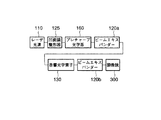
図19は、音響光学素子130が、レーザ波長の高速選択(切換え)手段、調光(出射パワー調整機構)手段、及びそのスイッチング機能を利用したパルス成形手段、シャッタ手段として使用された例を示す図である。この従来例に係るレーザ走査型顕微鏡の詳細については、特許文献1に示されている。ArやArKr110a、HeNe110b、110cの短波長レーザが複数設置され、それらレーザの出射ビームがダイクロイックミラー等により1本のビームに合成され音響光学素子130に入射する。音響光学素子130は、そのRF周波数制御により波長選択が、RF振幅〈電圧〉制御により出射パワーが、RF−ON/OFFスイッチング制御により連続発振レーザのパルス成形が高速に可能である。
19 and 20 show usage examples of acousto-optic elements in a laser scanning microscope.
FIG. 19 shows an example in which the
図20は、レーザ光源に波長切換え可能なパルスレーザ(レーザ光源)110を用いた例を示す。音響光学素子130はレーザ光源の選択された波長に従い、RF周波数制御することで、選択された波長のレーザを出射すると共に、RF振幅(電圧)制御により出射ビームのパワー制御が可能である。
FIG. 20 shows an example in which a pulse laser (laser light source) 110 capable of switching the wavelength is used as the laser light source. The
しかし、音響光学素子130に使用される結晶(LiNbO3、PbMoO4、TeO2)は非常に波長分散(群速度遅延の分散;GDD)が大きく、音響光学素子130により出射後のビームのパルス幅が広げられてしまうという欠点がある。多光子励起レーザ走査型顕微鏡では蛍光発光強度が2光子励起の場合はパルス幅に、3光子励起の場合はパルス幅の2乗に反比例するため、非常に大きな影響を及ぼす。
However, crystals (LiNbO 3 , PbMoO 4 , TeO 2 ) used for the
この音響光学素子130の波長分散(GDD)による出射ビームのパルス幅広がり対策として、特許文献2の手段を図21に示す。これはパルスレーザ光源110と音響光学素子間にプレチャープ光学系を挿入し、音響光学素子、もしくはレーザ出射後観察標本に達するまでの全光学系の波長分散量(GDD)分の逆分散(プレチャープ)行うことで、音響光学素子出射後、もしくは観察標本面でのパルス幅の広がりを相殺したものである。
FIG. 21 shows the means of Patent Document 2 as a countermeasure against the broadening of the pulse width of the outgoing beam due to the wavelength dispersion (GDD) of the
図22にプリズムを用いた代表的なプレチャープ光学系概略図を示す。図中の第1プリズム161で分光されたビームは、波長分散量(レーザ光帯域内の波長による媒質伝播速度ずれ)に応じた光路長差に設定された第2プリズム162により逆分散され第1プリズム161を再経由し、顕微鏡照明光学系内に戻されることにより、照明光学系内の波長分散を相殺することが出来る。
FIG. 22 shows a schematic diagram of a typical pre-chirped optical system using a prism. The beam dispersed by the
次に、特許文献3記載の音響光学素子の波長分散(GDD)量を利用したパルス圧縮手段につき、図23に基づき説明する。パルスレーザをレーザ光源110とし、光ファイバー185を顕微鏡への導入に用いた照明光学系を有するレーザ顕微鏡において、光ファイバー185の持つ線形及び非線形分散効果を避けるために、ファイバー入射側では先に示したプレチャープ光学系(逆分散)等のパルス伸長器180により、パルス幅を充分拡げると共にピークパワーを充分下げる必要がある。しかし、多光子励起レーザ顕微鏡では、先に示した様に必要な蛍光発光強度を得るためには、パルス幅が充分狭い必要があり、パルス伸長器、ファイバーを経てパルス幅の広がったビームでは標本面上の光子密度が低く、多光子励起が出来ない。そこでファイバー出射端に例えばZnSeといった波長分散量(GDD)の大きな光学部材を設置し、パルス幅を圧縮することで必要なパルス幅を得ることが行われている。音響光学素子も先に述べた様に、波長分散量(GDD)が充分大きいため、同様にパルス圧縮器としで用いることが出来る。ここで、音響光学素子を使用する利点は、波長選択手段、調光(パワー調整)手段、スイッチング手段としても利用できる点である。
Next, pulse compression means using the amount of chromatic dispersion (GDD) of the acoustooptic device described in Patent Document 3 will be described with reference to FIG. In the laser microscope having the illumination optical system in which the pulse laser is the
以上従来技術として、主に音響光学素子について述べたが、電気光学素子についても同様にレーザ走査型顕微鏡への応用が考えられる。
上記のように、音響光学素子又は電気光学素子はレーザ走査型顕微鏡において有用な素子であるが、以下のような問題点を有する。 As described above, the acousto-optic element or the electro-optic element is a useful element in a laser scanning microscope, but has the following problems.
使用するレーザに対する音響光学素子又は電気光学素子の開口部が小さい。このため、レーザ光をガウシアンビームであるものと想定しても、任意の位置でのビーム径はビームウエスト位置でのビーム径と広がり角により変化し、音響光学素子又は電気光学素子の開口部でケラレた分のパワーロスが生じる。 The aperture of the acousto-optic element or electro-optic element for the laser used is small. For this reason, even if it is assumed that the laser beam is a Gaussian beam, the beam diameter at an arbitrary position varies depending on the beam diameter and the divergence angle at the beam waist position, and at the opening of the acousto-optic element or electro-optic element. A power loss corresponding to the vignetting occurs.
また、音響光学素子又は電気光学素子の入射光に対する出射光の角度分散により、光源となるレーザのガウシアンビームの広がり角により、出射ビームがより広がってしまう。 Further, due to the angular dispersion of the emitted light with respect to the incident light of the acousto-optic element or the electro-optic element, the emitted beam is further spread by the spread angle of the Gaussian beam of the laser serving as the light source.
更に、レーザ光源内部構造により、出射レーザの縦横方向でのビームウエスト位置、広がり角に差が生じる。これにより、ビーム整形手段以前に、顕微鏡入射ビームの形状としても焦点座標や焦点面でのレーザ強度、光子密度的に誤差を生じる。 Further, due to the internal structure of the laser light source, a difference occurs in the beam waist position and spread angle in the vertical and horizontal directions of the emitted laser. As a result, before the beam shaping means, an error occurs in the focal coordinate, the laser intensity at the focal plane, and the photon density as the shape of the microscope incident beam.
また、音響光学素子又は電気光学素子の開口部と顕微鏡入射第一瞳径〈レーザ光投影瞳共役面〉とが異なる場合に、投影されたレーザ光が顕微鏡瞳径より大きい場合は、ビームのケラレによるパワーロスが、瞳径より小さい場合はNA不足による解像劣化等が生じる。 Further, when the aperture of the acousto-optic element or the electro-optic element is different from the first entrance pupil diameter <laser beam projection pupil conjugate plane>, if the projected laser beam is larger than the microscope pupil diameter, beam vignetting will occur. If the power loss due to is smaller than the pupil diameter, resolution degradation or the like due to insufficient NA occurs.
更に、パルスレーザ等の波長切換え可能なレーザ光源を用いた場合において、その波長切換え時ビーム位置等がずれる。これは音響光学素子又は電気光学素子が持つ入射ビームの角度に対する出射ビームパワー特性変化が大きなこと、また、瞳投影式のレーザ走査型顕微鏡の場合は視野のケラレ、ムラ、他のレーザによる観察像との位置ずれ等の問題がある。従って、顕微鏡等の光学的精度を求める部位に出力光を導入する場合には、波長ごとに素子への入力信号や素子前後の入出力光の最適化など、数多くの最適化調整を行う必要があり、使用する波長が増えるほど各部調整が困難となる。 Further, when a laser light source capable of wavelength switching, such as a pulse laser, is used, the beam position at the time of wavelength switching is shifted. This is because the output power characteristics of the acousto-optic element or electro-optic element change greatly with respect to the angle of the incident beam. In the case of a pupil-projection laser scanning microscope, field vignetting, unevenness, and other images observed by other lasers. There are problems such as misalignment. Therefore, when the output light is introduced into the part where the optical accuracy is required such as a microscope, it is necessary to perform many optimization adjustments such as optimization of the input signal to the element and the input / output light before and after the element for each wavelength. Yes, the adjustment of each part becomes more difficult as the wavelength used increases.
本発明は、レーザ走査型顕微鏡のレーザ光源からのレーザ光を顕微鏡に導入する照明光学系内に、音響光学素子又は電気光学素子を備えたレーザ走査型顕微鏡において、レーザ光源からのレーザ光を有効かつ理想的に顕微鏡に導入するレーザ走査型顕微鏡を提供することを目的とする。 The present invention effectively uses laser light from a laser light source in a laser scanning microscope equipped with an acousto-optic element or electro-optic element in an illumination optical system that introduces laser light from a laser light source of a laser scanning microscope into the microscope. An object of the present invention is to provide a laser scanning microscope ideally introduced into a microscope.
本発明の一局面に係る発明は、レーザ光源からレーザ光を顕微鏡に導入する照明光学系内に、音響光学素子又は電気光学素子を備えたレーザ走査型顕微鏡において、前記レーザ光源から出射された前記レーザ光の波長に起因する前記レーザ光の位置ずれ、前記レーザ光の角度ずれ及び前記レーザ光のビーム径のずれを補正、又は前記レーザ光の位置ずれ、前記レーザ光の角度ずれ及び前記レーザ光のビームの広がりずれを補正、又は前記レーザ光の位置ずれ、前記レーザ光の角度ずれ、前記ビーム径のずれ及び前記ビームの広がりずれを補正するための調整機構と、前記波長に対応した前記補正の補正値を記憶する記憶手段と、前記レーザ光の前記波長の切換えに伴い、前記記憶手段に記憶された、切換えられた前記波長に対応した前記補正値を用いて前記調整機構を自動的に調整する補正手段と、を具備することを特徴とする。 The invention according to one aspect of the present invention is directed to a laser scanning microscope including an acousto-optic element or an electro-optic element in an illumination optical system that introduces laser light from a laser light source into the microscope. position of the laser beam deviation caused by the wavelength of the laser beam, corrects the angular deviation and the deviation of the beam diameter of the laser beam of the laser beam, or positional deviation of the laser beam, the angular deviation of the laser beam and the laser beam An adjustment mechanism for correcting misalignment of the laser beam, or positional deviation of the laser beam, angular misalignment of the laser beam, misalignment of the beam diameter and misalignment of the beam, and the correction corresponding to the wavelength the storage means for storing correction values, with the switching of the wavelength of the laser beam, which is stored in the storage means, the correction corresponding to the wavelength switched Characterized by comprising a correction means for automatically adjusting the adjustment mechanism used.
本発明によれば、レーザ走査型顕微鏡のレーザ光源からのレーザ光を顕微鏡に導入する照明光学系内に、音響光学素子又は電気光学素子を備えたレーザ走査型顕微鏡において、レーザ光源からのレーザ光を有効かつ理想的に顕微鏡に導入するレーザ走査型顕微鏡を提供することができる。 According to the present invention, in a laser scanning microscope having an acousto-optic element or an electro-optic element in an illumination optical system that introduces laser light from a laser light source of a laser scanning microscope into the microscope, laser light from the laser light source is provided. It is possible to provide a laser scanning microscope that effectively and ideally introduces the above into the microscope.
図面を参照して本発明の実施の形態を説明する。
図1は、本発明の実施形態に係るレーザ顕微鏡の概略構成を示す図である。なお、以下の各実施形態において、レーザ顕微鏡の概略構成は図1と同様であるので、図1を援用するものとする。
走査型レーザ顕微鏡は、レーザ制御部100と、レーザ走査部200と、顕微鏡300とを備えている。レーザ制御部100は、レーザ光を出射するレーザ光源110と、レーザ光のON/OFFスイッチ・調光・波長選択を行う音響光学素子130と、レーザ顕微鏡の動作を制御するPC140とからなっている。レーザ走査部200は、レーザ光を走査させる機構であるガルバノメータミラー210と、標本310で発生した蛍光を電気信号に変換する光電変換器220とからなっている。顕微鏡300は、標本310を観察するための対物レンズ320を備えている。また、モニタ400は観察象を表示するために使用される。また、PC140は、音響光学素子130、ガルバノメータミラー210及び光電変換器220と信号線で接続されている。
Embodiments of the present invention will be described with reference to the drawings.
FIG. 1 is a diagram showing a schematic configuration of a laser microscope according to an embodiment of the present invention. In the following embodiments, the schematic configuration of the laser microscope is the same as that in FIG. 1, and therefore FIG. 1 is used.
The scanning laser microscope includes a
上記の構成において、レーザ光源110から出射されたレーザ光は音響光学素子130に入射する。音響光学素子130はPC140からの指令に基づいて、レーザ光をON/OFF制御、調光、波長選択する。音響光学素子130を通過したレーザ光はレーザ走査部200によって進行方向を偏向され2次元平面上を走査するように制御される。そして、レーザ光は顕微鏡300に入射し対物レンズ320によって標本310上を2次元に走査される。走査された標本310は光励起され蛍光を発する。発生した蛍光は対物レンズ320を介してレーザ光とは逆の光路を進み、ガルバノメータミラー210によって偏向が解除された後、光電変換器220に入射する。光電変換器220で変換された信号は、PC140に入力される。PC140は、ガルバノメータミラー210の走査状態を表す信号と光電変換器220からの信号とを対応付けて、標本310の蛍光像を構成し、モニタ400にその画像を表示する。
In the above configuration, the laser light emitted from the
(第1の実施形態)
図2は、本発明の第1の実施形態に係るレーザ顕微鏡の要部構成を示す図である。図2において、レーザ走査部200は省略しており、更に、顕微鏡300も簡略化して示している。なお、以下の実施形態においても同様である。
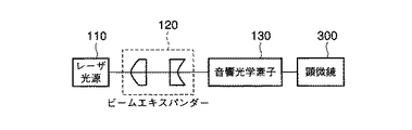
第1の実施形態では、レーザ光源110と音響光学素子130(電気光学素子でも良い。なお、以下の説明では、説明の便宜上、音響光学素子と電気光学素子とを併せて、単に「音響光学素子」と称する)との間に、ビームエキスパンダー120が配置されている。このビームエキスパンダー120は、レーザ光源110より出射されたレーザ光を音響光学素子130の開口部の径内にコリメーションする。これにより、音響光学素子130の開口部によるレーザ光のケラレをなくしている。更に、ビームエキスパンダー120で、レーザ光を平行ビームに整形することで、音響光学素子130による角度分散を無くしている。このように、レーザ光源110を出射したレーザ光は、ビームエキスパンダー120で平行ビームに整形された後に音響光学素子130に入射する。音響光学素子130に入射したレーザ光は、所望の強度にされると共に、所望の波長のみが選択されて、顕微鏡300に入射して、図示しない試料に照射される。
(First embodiment)
FIG. 2 is a diagram showing a main configuration of the laser microscope according to the first embodiment of the present invention. In FIG. 2, the
In the first embodiment, the
(第2の実施形態)
図3は、本発明の第2の実施形態に係るレーザ顕微鏡の要部構成を示す図である。なお、図3において、図2と同じ部分には同じ符号を付している。本第2の実施形態では、第1の実施形態の構成にレーザ光整形器として凹面鏡整形器150を追加している。このように、本第2の実施形態はレーザ出力の後段(すなわち、レーザ光源とビームエキスパンダーとの間)にレーザ光整形器を配置したことを特徴とする。以下、レーザ光整形器の必要性について説明する。
(Second Embodiment)
FIG. 3 is a diagram showing a main configuration of a laser microscope according to the second embodiment of the present invention. In FIG. 3, the same parts as those in FIG. In the second embodiment, a
まずレーザ光源からの通常の出力光の断面形状(すなわち、ビーム形状)について図4を参照して概略説明する。
レーザ発振器111から出射されたレーザ光は、集光ミラー112によりコリメーションされ、集光ミラー113と114によりレーザ結晶115に集光され、高反射ミラー116と出力結合ミラー117間を繰り返し共振することで図示しないレーザ筐体より出射される。このときレーザ結晶115に集光する凹面集光ミラー113及び114はZ型に配置されているため、ビームの断面方向での曲率が異なる。このため、図4に示すような、楕円形の断面形状を有するビーム、すなわち、ビームウエスト位置、ビーム径、広がり角のずれたビームが出射されることとなる。ここで、レーザ光を音響光学素子に有効に入射させるためには、レーザ光の断面形状を楕円から円形にすることが好ましい。
First, a cross-sectional shape (that is, a beam shape) of normal output light from a laser light source will be schematically described with reference to FIG.
The laser light emitted from the
本実施形態は、レーザ光源110出射後にレーザ筐体内部と逆の曲率方向に凹面鏡ビーム整形器125を追加したことを特徴としており、これにより、上記のようなレーザ光源110より出射されたビームの断面方向でのずれが解消できる。
この凹面鏡ビーム整形器125を経たビームは、その断面形状が円形の波面が均−な理想的なガウシアンビームになる。このため、上記第1の実施形態に示したビームエキスパンダー120や顕微鏡300の内部光学系を通過したビームも、標本面上により正確に集光される。これは多光子励起レーザ走査型顕微鏡の様に対物レンズにより集光されたビームの光子密度により励起効率が左右され、かつ3次元効果を得る検鏡法では特に有効である。なお、この凹面鏡ビーム整形器125は、それ以降の光学系の影響を避けるため、レーザ筐体直後に配置することが望ましい。また、特定波長時の整形であればシリンドリカルレンズ等レンズ構成によっても可能である。しかし、パルスレーザの場合はレンズの波長分散(GDD)による影響や、複数の波長を切換え、もしくは選択するレーザ光源110においては波長によるレンズ間隔調整等が発生するため、凹面鏡が最も好ましい。また、凹面鏡ビーム整形器125の使用は、音響光学素子130を用いないレーザ走査型顕微鏡の照明光学系にも当然有効である。
The present embodiment is characterized in that a concave
The beam that has passed through the concave
(第3の実施形態)
図5は、本発明の第3の実施形態に係るレーザ顕微鏡の要部構成を示す図である。なお、図5において、図2及び図3と同じ部分には同じ符号を付している。本第3の実施形態は、音響光学素子130の後段にビームエキスパンダー120を設けたことを特徴とする。
(Third embodiment)
FIG. 5 is a diagram showing a main configuration of a laser microscope according to the third embodiment of the present invention. In FIG. 5, the same parts as those in FIGS. 2 and 3 are denoted by the same reference numerals. The third embodiment is characterized in that a
音響光学素子130の後段に設置されたビームエキスパンダー120について述べる。音響光学素子130の開口部に対し必要な径にコリメートされたビーム径は、必ずしも顕微鏡の瞳径(レーザ光を投影する瞳共役位置での径)に一致するとは限らない。よって音響光学素子130出射後のビームを顕微鏡入射に適正な径にコリメートする手段が必要となり、これが図5の音響光学素子130後に配置されたビームエキスパンダー120である。仮にレーザ出射ビームが音響光学素子130開口部に対し充分小さな径のビームであったり、開口部によるビームのケラレがあっても、顕微鏡観察に充分なパワーがある場合、音響光学素子130前段のビームエキスパンダー120は不要になる場合もある。また、音響光学素子130の波長分散によるパルス幅補正用のプレチャープ光学系160を音響光学素子130後段に設置することで、レーザ光源110出射後、ビームが広がらないうちに音響光学素子130ヘビームを入射できれば、同様に音響光学素子130前段のビームエキスパンダー120は省略することが可能である。しかし、顕微鏡入射ビームに関しては、少なくとも瞳に対して適正な径に、かつ平行光にコリメートされなければ、焦点位置のずれや、分解能の劣化等標本観察に重大な支障をきたすこととなる。なお、図5において、プレチャープ光学系160は、音響光学素子130の後段に配置しても良い。
The
(第4の実施形態)
図6は、本発明の第4の実施形態に係るレーザ顕微鏡の要部構成を示す図である。なお、図6において、図2〜図5と同じ部分には同じ符号を付している。本第4の実施形態では、レーザ光源からのレーザ光の各波長における最適な変調入力信号を自動的に算出することを特徴とする。
(Fourth embodiment)
FIG. 6 is a diagram showing a main configuration of a laser microscope according to the fourth embodiment of the present invention. In FIG. 6, the same parts as those in FIGS. The fourth embodiment is characterized in that an optimum modulation input signal at each wavelength of laser light from a laser light source is automatically calculated.
PC140が波長選択の切替信号をレーザ光源110に送ることにより、レーザ光源110におけるレーザ発振波長が選択されて単一波長の光が出射される。レーザ光源110から出射されたレーザ光は音響光学素子130に入射する。音響光学素子130はドライバ141からの変調入力信号(RF信号)の周波数と振幅に基づいて、レーザ光をON/OFF制御、調光、及び波長選択する。音響光学素子130を通過したレーザ光はビームスプリッタ135cで2つの光路に分岐され、それぞれ検出器150cと顕微鏡300へ入射する。ここで、検出器150cに入射したレーザ光は光電変換されてPC140に入力される。PC140は、ドライバ141に対して変調入力信号の振幅と周期を指定することができるように構成されており、常に検出器150cからの光電変換信号をモニタしながら変調入力信号の振幅を変化させていき、光電変換信号の値が最大となる変調入力信号の振幅を算出する。
これにより、選択した波長ごとの最適変調入力周波数(音響光学素子130からの強度が最大となる時のRF周波数)を自動的に検出することができる。
When the
As a result, the optimum modulation input frequency (RF frequency when the intensity from the
(第5の実施形態)
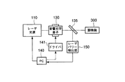
図7は、本発明の第5の実施形態に係るレーザ顕微鏡の要部構成を示す図である。なお、図7において、図2〜図6と同じ部分には同じ符号を付している。本第5の実施形態では、レーザ光源の波長切換え時におけるビーム径と位置ずれを自動的に補正することを特徴とする。
(Fifth embodiment)
FIG. 7 is a diagram showing a main configuration of a laser microscope according to the fifth embodiment of the present invention. In FIG. 7, the same parts as those in FIGS. The fifth embodiment is characterized in that the beam diameter and the positional deviation at the time of switching the wavelength of the laser light source are automatically corrected.
第5の実施形態では、図7に示すように、第4の実施形態に、レーザ光のビーム径とビーム広がり角を可変にするビームエキスパンダー120と、レーザ光のビームを平行移動と角度変化させることができるビームシフター145と、レーザ光のON/OFFスイッチ・調光・波長選択を行う音響光学素子130へ光路を分岐する為のビームスプリッタ135aと、レーザ光をビームの位置を検知するCCDなどの位置検出器150aとが追加されている。
In the fifth embodiment, as shown in FIG. 7, in the fourth embodiment, a
ビームエキスパンダー120は回転することによりビーム径、ビームの広がり角が可変となる光学素子と、位置検出センサとモータを組み合わせたものである。
The
また、ビームシフター145の構成例を図8に示す。図8に示すように、ビームシフター145は2枚の平面ミラー145aと145bと図示しない位置検出センサとモータを組み合わせたものである。
An example of the configuration of the
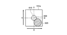
上記のように構成されたレーザ顕微鏡において、第4の実施形態と同様に、PC140から波長選択の切替信号レーザ光源110に送り、レーザ光源110からのレーザ発振波長を選択し単一波長の光が出射するようにする。レーザ光源110から出射されたレーザ光は、レーザ光のビーム径とビーム広がり角を可変にするビームエキスパンダー120と、レーザ光のビームを平行移動とビームの角度変化を可能とするビームシフター145を通過する。通過したレーザ光は、ビームスプリッタ135aで分岐されて、それぞれ検出器150aと音響光学素子130へ入射する。レーザ光が音響光学素子130の最適な位置に最適な径で入射する時に、図9に示すように、レーザ光が検出器150aの素子151a上の中心600にビームスポット610の中心が来るようにビームスプリッタ135aと検出器150aを設置する。検出器150aに入射した光は光電変換され素子151aの画素ごとの輝度情報がPC140に入力される。PC140はビームエキスパンダー120と、ビームシフター145のミラー145a、145bを駆動するパルス信号を各駆動部に対して出力する。ビームシフター145は図8の破線146a、146bを軸にモータがそれぞれの軸でX軸Y軸を駆動するようになっており、2枚のミラー145a、145bの面を同じ角度ずつ傾けるとビームは平行移動する。なお、音響光学素子130に入射後の動作は第4の実施形態と同様なので省略する。
In the laser microscope configured as described above, similarly to the fourth embodiment, a wavelength selection switching signal is sent from the
図9を参照して、波長切換え後における最適化調整の手順を説明する。
1.ビームシフター145にて、理想のビームスポット610の中心と、実際のビームスポット620の中心とが一致するようにレーザ光を平行移動させる。
2.ビームエキスパンダー120にて、理想のビームスポット610の径と実際のビームスポット620の径が同じ大ききとなるように調整する。
3.第4の実施形態で記載した方法で変調入力信号の最適化調整を行う。
上記の手順により最適化を行うことができる。具体的な調整方法は以下のとおりである。
With reference to FIG. 9, the procedure of optimization adjustment after wavelength switching will be described.
1. In the
2. The
3. The modulation input signal is optimized and adjusted by the method described in the fourth embodiment.
Optimization can be performed by the above procedure. The specific adjustment method is as follows.
ビームシフター145を用いて、レーザ光を中心位置に平行移動させる方法は、以下のとおりである。PC140が常に検出器150aからの光電変換信号をモニタしながら、素子151aに照射されたビームスポット620の中心座標を中心600に移動するようにミラー145a、145bの面が平行状態を常に保った状態で、モータでミラーの2軸504を中心にミラーを駆動する。なお、ビームスポット620の中心座標の求め方はビームがガウシアン型だと仮定し強度の最も高い座標を中心座標とする方法、もしくはビームが真円と仮定して例えばX座標Y座標それぞれの最大値と最小値の中間の座標を中心座標とする方法など種々の方法がある。
A method of translating the laser light to the center position using the
ビームエキスパンダー120でレーザ光の径を調整する方法は、以下のとおりである。PC140が常に検出器150aからの光電変換信号をモニタしながら、素子151aに照射されたレーザのビームスポット620が理想のビームスポット610の径と同じになるようにビームエキスパンダー120を回転駆動させる。ビーム径の大ききの判断方法として、例えばビームスポットが真円であると仮定してX座標の最大値最小値の差とする方法がある。また、波長切換えにより、ビーム径の変化がない場合にはビームエキスパンダー120は一旦調整後はそのまま固定し、以降無調整としても良い。
A method of adjusting the diameter of the laser beam with the
第5の実施形態により、第4の実施形態に加えて、レーザの波長切換えなどによりビームの位置が平行移動したり、レーザ光径が変化した場合にでも自動的に最大の効率でレーザ光を顕微鏡まで導くことが可能である。 According to the fifth embodiment, in addition to the fourth embodiment, even when the position of the beam is translated by laser wavelength switching or the laser beam diameter is changed, the laser beam is automatically emitted with the maximum efficiency. It is possible to guide to a microscope.
(第6の実施形態)
図10は、本発明の第6の実施形態に係るレーザ顕微鏡の要部構成を示す図である。なお、図10において、図2〜図7と同じ部分には同じ符号を付している。本第6の実施形態では、第4の実施形態と第5の実施形態に加えて、レーザ光源の波長切換え時におけるビームの広がりと角度ずれを自動的に補正することを特徴とする。
(Sixth embodiment)
FIG. 10 is a diagram showing a main configuration of a laser microscope according to the sixth embodiment of the present invention. In FIG. 10, the same parts as those in FIGS. The sixth embodiment is characterized in that, in addition to the fourth and fifth embodiments, the beam spread and the angular deviation are automatically corrected when the wavelength of the laser light source is switched.
第6の実施形態に係るレーザ顕微鏡は、第5の実施形態に係るレーザ顕微鏡に、ビームシフター145と音響光学素子130との間に設けられた2つのビームスプリッタ135aと135bと、各ビームスプリッタ135a、135bの反射光路に設けられたビーム位置を検出するCCDなどの検出器150a、150bとを追加している。以下、第6の実施形態に係るレーザ顕微鏡の動作を説明する。
The laser microscope according to the sixth embodiment is the same as the laser microscope according to the fifth embodiment except that two
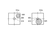
第5の実施形態と同様に、レーザ光源110から出射されたレーザ光は、ビームエキスパンダー120と、ビームシフター145とを通過した後に、ビームスプリッタ135aで分岐されて、それぞれ検出器150aと音響光学素子130に入射する。レーザ光が音響光学素子130の最適な位置に最適な径で最適な角度で平行光として入射する時に、図11に示すように、レーザ光が検出器150aの素子135aと検出器150aの素子151a上の中心600とビームスポット620の中心とが一致するようにビームスプリッタ135a、135bと検出器150a、150bを設置する。検出器150a、150bに入射した光は光電変換されて検出器150aの素子151aと検出器150bの素子151bの各画素ごとの輝度情報がPC140に入力される。PC140はビームエキスパンダー120と、ビームシフター145のミラー145a、145bを駆動するパルス信号を各駆動部に対して出力する。ビームシフター145は前述した図8の破線146a、146bを軸にモータがそれぞれの軸でX軸Y軸を駆動するようになっており、2枚のミラー145a、145bを同じ角度ずつ傾けるよう駆動するとビームは平行移動し、どちらか1方のミラーを駆動するとビーム角度を変える事ができる。なお、音響光学素子130に入射後の動作は第4の実施形態と同様なので省略する。
Similar to the fifth embodiment, the laser light emitted from the
図12〜図16を参照して、波長切換え後における最適化調整の手順を説明する。
1.ビームシフター145にて素子151aのビームスポット620の中心と、素子151bのビームスポットの中心625が一致するようにレーザ光の傾きを変化させる。(図12参照)
2.第5の実施形態に記載した方法と同様の方法でビームシフター145にて素子151aのビームスポット620の中心と、素子151bのビームスポットの中心625が素子151bの中心と一致するようにレーザ光を平行移動させる。(図13参照)
3.ビームエキスパンダー120にて素子151aのビームスポット620の径に、素子151bのビームスポット625の径が一致するようにレーザ光のビームの広がりを変化させる。(図14参照)
4.第5の実施形態に記載した方法と同様の方法でで、ビームエキスパンダー120にて理想のビームスポット610の径と実際のビームスポット620、625の径が同じ大きさとなるようにビーム径を変化させる。(図15参照)
5.第4の実施形態で記述した方法と同様の方法で変調入力信号の最適化調整を行う。
上記の手順により最適化を行うことができる。具体的な調整方法は以下のとおりである。
A procedure for optimization adjustment after wavelength switching will be described with reference to FIGS.
1. The tilt of the laser beam is changed by the
2. In the same manner as the method described in the fifth embodiment, the
3. The
4). In the same manner as described in the fifth embodiment, the
5. Optimization adjustment of the modulation input signal is performed by the same method as that described in the fourth embodiment.
Optimization can be performed by the above procedure. The specific adjustment method is as follows.
ビームシフター145を用いて素子151a上に照射されたビームスポット620の中心と、素子151b上に照射されたビームスポットの中心600とを一致させる方法は、以下のとおりである。PC140が常に検出器150aと135bからの光電変換信号をモニタしながら、ビームスボツト620と625の中心座標が同じになるようにミラー145aのみを、モータでミラーの2軸504を中心にミラーを駆動する。なお、ビームスポット620、625の中心座標の求め方は第5の実施形態に記載したとおりである。
A method of aligning the center of the
ビームエキスパンダー120でレーザ光のビームの広がりを調整する方法は、以下のとおりである。PC140が常に検出器150aからの光電変換信号をモニタしながら、素子151b上に照射されたビームスポット625の径が素子151a上に照射されたビームスポット620の径と同じになるようにビームエキスパンダー120を回転駆動させる。なお、ビーム径の大ききの判断方法及びその他の調整は弟5の実施形態に記載したとおりである。また、波長切換えによりビーム径の変化、ビームの広がりがない場合はビームエキスパンダー120は一旦調整後はそのまま固定し、以降無調整としても良い。
A method of adjusting the spread of the laser beam by the
第6の実施形態により、レーザの波長切換えなどによりビームの出射角度が変化したり、レーザ光の広がり角が変化した場合にでも自動的に最大の効率でレーザ光を顕微鏡まで導くことが可能である。それ以外の効果は第5の実施形態と同様である。 According to the sixth embodiment, it is possible to automatically guide the laser beam to the microscope with the maximum efficiency even when the beam emission angle is changed by switching the wavelength of the laser or the spread angle of the laser beam is changed. is there. The other effects are the same as in the fifth embodiment.
(第7の実施形態)
第7の実施形態は、レーザ光の波長ごとの各部の補正値や、最適値をPC内に記憶させておき、記憶させた波長を再び使用する際には、記憶した補正値や、最適値を用いてにレーザ光の径など補正を行う機能を付加した。なお、本実施形態は、補正をする場合に、自動で各部調整を行わなわないで、手動で上記各部の調整を行った場合にも適用可能である。
(Seventh embodiment)
In the seventh embodiment, correction values and optimum values of each part for each wavelength of the laser light are stored in the PC, and when the stored wavelengths are used again, the stored correction values and optimum values are stored. A function for correcting the laser beam diameter and the like was added. Note that the present embodiment can also be applied to the case where the respective parts are adjusted manually without performing the automatic adjustment of each part when correction is performed.
第7の実施形態に係るレーザ顕微鏡の構成は、図10と同様であるので、図示を省略する。なお、本実施形態においては、例えばPC140用の図示しない記憶装置が、記憶用に使用される。
The configuration of the laser microscope according to the seventh embodiment is the same as that shown in FIG. In the present embodiment, for example, a storage device (not shown) for the
例えば、第4〜第6の実施形態に記載したとおりに各部の調整終了すると、PC140の記憶装置は、例えば、
・現在選択しているレーザ光の波長
・ビームエキスパンダー120の回転角度
・ビームシフター145のミラー145a、145bのXY軸の回転角度
・ドライバ141が音響光学素子130に与える変調入力信号の周波数
を記憶する。この場合において、ビームエキスパンダー120やビームシフター145の駆動部角度は第5の実施形態に記載した位置検出センサにより現在位置を認識することができる。
For example, when the adjustment of each unit is completed as described in the fourth to sixth embodiments, the storage device of the
・ The wavelength of the currently selected laser beam
・ Rotation angle of
-XY axis rotation angle of
The frequency of the modulation input signal that the
Remember. In this case, the current position of the drive unit angle of the
上記のレーザ光の波長ごとのデータが、記憶装置に記憶されている場合に、レーザ波長を所望の波長に切換えた場合、選択したレーザ光の波長が記憶装置に記憶されているかどうか判断する。記憶装置に当該波長に係るデータがなければ、第4〜第6の実施形態記載の通り各部再調整を行う。なお、各部の調整は、自動調整でなく、手動で上記各部の調整を行い、調整後の各部のデータを調整データとして記憶しておき、当該データを調整データとして記憶しておいても良い。
もし選択したレーザ光の波長が記憶装置に記憶されていれば、当該波長に係る各部の調整データを記憶装置から読み出して、当該調整データを各部に対して与える。
When the data for each wavelength of the laser beam is stored in the storage device, when the laser wavelength is switched to a desired wavelength, it is determined whether the wavelength of the selected laser beam is stored in the storage device. If there is no data relating to the wavelength in the storage device, each part is readjusted as described in the fourth to sixth embodiments. The adjustment of each part may be performed by adjusting each part manually instead of automatic adjustment, storing the adjusted data of each part as adjustment data, and storing the data as adjustment data.
If the wavelength of the selected laser beam is stored in the storage device, the adjustment data of each part related to the wavelength is read from the storage device, and the adjustment data is given to each part.
上記のように、ある波長で一旦各部の調整しておいて、そのときの各部のデータを当該波長に対する調整データとして記憶しておくことにより、再度その波長を使用する際に、波長を切換えるごとに各部再調整を行わなくてすむので、波長を切換えてから素早く調整の必要な各部を最適化することができる。 As described above, each part is adjusted once at a certain wavelength, and the data of each part at that time is stored as adjustment data for that wavelength. Therefore, it is not necessary to readjust each part, so that it is possible to optimize each part that needs to be adjusted quickly after switching the wavelength.
本発明は、上記各実施の形態に限ることなく、その他、実施段階ではその要旨を逸脱しない範囲で種々の変形を実施し得ることが可能である。 The present invention is not limited to the above-described embodiments, and various modifications can be made without departing from the scope of the invention at the stage of implementation.
上記の実施形態では、レーザ光源110は、多光子レーザを想定したが、単色レーザを組み合わせて、シャッタで出力波長を切換えてもよい。
また、第4の実施形態から第6の実施形態において、第2の実施形態に示すようなレーザ光整形器としての凹面鏡整形器や第3の実施形態に示すようなプレチャープ光学系を設けても良い。なお、凹面鏡整形器やプレチャープ光学系を設ける場合には、レーザ光源110とビームエキスパンダー120との間に設けることが好ましい。
更に、第4の実施形態から第6の実施形態において、第3の実施形態に示すように、音響光学素子130の後段にビームエキスパンダー120bを設けても良い。ここで、音響光学素子130を出射したレーザ光は、その波長に関わらずビーム位置と角度のずれ及び光束径と光束の広がりが正しく調整されているので、音響光学素子130後段に設けるビームエキスパンダーはレーザ波長に応じた調整を行わなくても良い。
In the above embodiment, the
Further, in the fourth to sixth embodiments, a concave mirror shaper as a laser light shaper as shown in the second embodiment or a pre-chirp optical system as shown in the third embodiment may be provided. good. In addition, when providing a concave mirror shaper and a pre-chirp optical system, it is preferable to provide between the
Furthermore, in the fourth to sixth embodiments, as shown in the third embodiment, a
上記の各実施形態によれば、以下のような効果が得られる。
(1)音響光学素子前段にビームエキスパンダーを配置したので、音響光学素子の開口部によるケラレがなくレーザ光のパワーを効率的に使用可能である。また、音響光学素子の角度分散の影響を無くし、不要なビームの広がりを抑えることが出来る。
(2)レーザ出射直後に置かれた凹面鏡ビーム整形器でビーム断面及び波面を理想的形状にすることで、照明光学系のビームの伝播、標本面上での集光を理想的に整形出来る。
(3)音響光学素子の前段に置かれたビーム位置検出器、もしくは音響光学素子の前・後段に置かれたレーザパワー検出器、及び音響光学素子前段に置かれたビーム位置補正機構で音響光学素子入射ビーム位置を調整することで、音響光学素子出射ビームパワーを効率的(最大)に調整することが出来る。
(4)音響光学素子の波長分散によるパルス時の広がりを補正するプレチャープ光学系を音響光学素子後段に放置することにより、レーザ光源から音響光学素子間の光路長を短くし、入射ビームの不要な広がりを極小化することで、音響光学素子前段のビームエキスパンダーを省略し、照明光学系を簡素にすることが出来る。
(5)音響光学素子後段に置かれたビームエキスパンダーにより、顕微鏡入射ビームを適正な径にコリメート出来る。
(6)選択した波長ごとの最適変調入力周波数(音響光学素子からの強度が最大となる時のRF周波数)を自動的に検出するようにしたので、最大の出力が得られる。
(7)各波長に対する最適値(補正値)を記憶するようにしたので、ある波長で1度調整すると、再度その波長を使用する時に、その度ごとに各部再調整を行わなくてすむので、波長を切換えてから素早く調整の必要な各部を最適化することができる。
According to the above embodiments, the following effects can be obtained.
(1) Since the beam expander is arranged in the previous stage of the acoustooptic device, there is no vignetting due to the opening of the acoustooptic device, and the power of the laser beam can be used efficiently. Further, the influence of the angular dispersion of the acoustooptic device can be eliminated, and the spread of unnecessary beams can be suppressed.
(2) By making the beam cross section and the wavefront ideal with a concave mirror beam shaper placed immediately after laser emission, the propagation of the beam of the illumination optical system and the focusing on the sample surface can be ideally shaped.
(3) Acousto-optics using a beam position detector placed in front of the acousto-optic device, or a laser power detector placed in front or back of the acousto-optic device, and a beam position correction mechanism placed in front of the acousto-optic device. By adjusting the element incident beam position, the acousto-optic element output beam power can be adjusted efficiently (maximum).
(4) By leaving the pre-chirp optical system that corrects the spread at the time of the pulse due to the wavelength dispersion of the acousto-optic device, the optical path length between the laser light source and the acousto-optic device is shortened, and no incident beam is required. By minimizing the spread, the beam expander in front of the acoustooptic device can be omitted, and the illumination optical system can be simplified.
(5) A beam expander placed downstream of the acoustooptic device can collimate the microscope incident beam to an appropriate diameter.
(6) Since the optimum modulation input frequency (RF frequency when the intensity from the acoustooptic device is maximized) for each selected wavelength is automatically detected, the maximum output can be obtained.
(7) Since the optimum value (correction value) for each wavelength is stored, if it is adjusted once at a certain wavelength, it is not necessary to readjust each part each time when using that wavelength again. Each part that needs to be adjusted quickly after switching the wavelength can be optimized.
上記のように本発明の実施形態によれば、レーザ光源より出射されたレーザ光を理想的に整形し顕微鏡に導入することで、顕微鏡の光学性能をより有効的に発揮させることが可能となる。 As described above, according to the embodiment of the present invention, the optical performance of the microscope can be more effectively exhibited by ideally shaping the laser light emitted from the laser light source and introducing it into the microscope. .
さらに、上記各実施形態には、種々の段階の発明が含まれており、開示される複数の構成要件における適宜な組合せにより種々の発明が抽出され得る。 Further, the above embodiments include inventions at various stages, and various inventions can be extracted by appropriately combining a plurality of disclosed constituent elements.
また、例えば各実施形態に示される全構成要件から幾つかの構成要件が削除されても、発明が解決しようとする課題の欄で述べた課題が解決でき、発明の効果で述べられている効果が得られる場合には、この構成要件が削除された構成が発明として抽出され得る。 In addition, for example, even if some structural requirements are deleted from all the structural requirements shown in each embodiment, the problem described in the column of the problem to be solved by the invention can be solved, and the effect described in the effect of the invention Can be obtained as an invention.
100…レーザ制御部、110…レーザ光源、111…レーザ発振器、112、113…集光ミラー、115…レーザ結晶、116…高反射ミラー、117…出力結合ミラー、120…ビームエキスパンダー、125…凹面鏡ビーム整形器、130…音響光学素子、135a、135b、135c…ビームスプリッタ、140…PC、141…ドライバ、145…ビームシフター、145a、145b…ミラー、150…凹面鏡整形器、150a、150b、150c…検出器、150b…検出器、151a…素子、151b…素子、160…プレチャープ光学系、161、162…プリズム、165…ビーム位置補正機構、180…パルス伸長器、185…光ファイバー、200…レーザ走査部、210…ガルバノメータミラー、220…光電変換器、220…光電検出器、300…顕微鏡、310…標本、320…対物レンズ、400…モニタ。
DESCRIPTION OF
Claims (3)
前記レーザ光源から出射された前記レーザ光の波長に起因する前記レーザ光の位置ずれ、前記レーザ光の角度ずれ及び前記レーザ光のビーム径のずれを補正、又は前記レーザ光の位置ずれ、前記レーザ光の角度ずれ及び前記レーザ光のビームの広がりずれを補正、又は前記レーザ光の位置ずれ、前記レーザ光の角度ずれ、前記ビーム径のずれ及び前記ビームの広がりずれを補正するための調整機構と、
前記波長に対応した前記補正の補正値を記憶する記憶手段と、
前記レーザ光の前記波長の切換えに伴い、前記記憶手段に記憶された、切換えられた前記波長に対応した前記補正値を用いて前記調整機構を自動的に調整する補正手段と、
を具備することを特徴とするレーザ走査型顕微鏡。 In a laser scanning microscope equipped with an acousto-optic element or an electro-optic element in an illumination optical system for introducing laser light from a laser light source into the microscope,
Correction of positional deviation of the laser light due to the wavelength of the laser light emitted from the laser light source , angular deviation of the laser light and deviation of the beam diameter of the laser light, or positional deviation of the laser light, the laser An adjustment mechanism for correcting an angular deviation of light and a beam spread deviation of the laser light, or correcting a positional deviation of the laser light, an angular deviation of the laser light, a deviation of the beam diameter, and a spread deviation of the beam ; ,
Storage means for storing a correction value of the correction corresponding to the wavelength;
With the switching of the wavelength of the laser light, and automatically adjusts to the correction means the adjustment mechanism using the correction value stored, corresponding to the wavelength is switched to the storage means,
A laser scanning microscope characterized by comprising:
前記検出手段からの前記検知信号に基づいて、前記音響光学素子又は前記電気光学素子を駆動する変調入力信号を出力する制御手段と、
前記レーザ光の前記波長における所定の最適な前記変調入力信号を自動的に算出する算出手段と、
を具備することを特徴とする請求項1に記載のレーザ走査型顕微鏡。 At least one detection means for detecting an output of the laser light emitted from the acousto-optic element or the electro-optic element and outputting a detection signal;
Control means for outputting a modulation input signal for driving the acousto-optic element or the electro-optic element based on the detection signal from the detection means;
A calculation means for automatically calculating a predetermined optimum modulation input signal at the wavelength of the laser beam;
The laser scanning microscope according to claim 1, comprising:
前記レーザ光の前記ビーム径のずれ及び前記ビームの広がりずれの少なくとも一方を補正するビームエキスパンダーと、
を具備することを特徴とする請求項1又は2に記載のレーザ走査型顕微鏡。 The adjustment mechanism includes a beam position correction mechanism that corrects the positional deviation and the angular deviation of the laser beam;
A beam expander for correcting at least one of the beam diameter shift and the beam spread shift of the laser light;
The laser scanning microscope according to claim 1, wherein the laser scanning microscope is provided.
Priority Applications (2)
| Application Number | Priority Date | Filing Date | Title |
|---|---|---|---|
| JP2004163360A JP4729269B2 (en) | 2004-06-01 | 2004-06-01 | Laser scanning microscope |
| US11/141,517 US7342219B2 (en) | 2004-06-01 | 2005-05-31 | Laser scanning microscope |
Applications Claiming Priority (1)
| Application Number | Priority Date | Filing Date | Title |
|---|---|---|---|
| JP2004163360A JP4729269B2 (en) | 2004-06-01 | 2004-06-01 | Laser scanning microscope |
Publications (3)
| Publication Number | Publication Date |
|---|---|
| JP2005345614A JP2005345614A (en) | 2005-12-15 |
| JP2005345614A5 JP2005345614A5 (en) | 2007-07-12 |
| JP4729269B2 true JP4729269B2 (en) | 2011-07-20 |
Family
ID=35424154
Family Applications (1)
| Application Number | Title | Priority Date | Filing Date |
|---|---|---|---|
| JP2004163360A Active JP4729269B2 (en) | 2004-06-01 | 2004-06-01 | Laser scanning microscope |
Country Status (2)
| Country | Link |
|---|---|
| US (1) | US7342219B2 (en) |
| JP (1) | JP4729269B2 (en) |
Cited By (1)
| Publication number | Priority date | Publication date | Assignee | Title |
|---|---|---|---|---|
| EP2827180A1 (en) | 2013-06-24 | 2015-01-21 | Olympus Corporation | Scanning optical microscope |
Families Citing this family (29)
| Publication number | Priority date | Publication date | Assignee | Title |
|---|---|---|---|---|
| JP4518549B2 (en) * | 2004-08-20 | 2010-08-04 | 正樹 小林 | Fluorescence tomographic image measuring device |
| JP4869734B2 (en) * | 2005-04-25 | 2012-02-08 | オリンパス株式会社 | Multi-photon excitation scanning laser microscope |
| ATE440301T1 (en) * | 2006-05-29 | 2009-09-15 | Olympus Corp | LASER SCAN MICROSCOPE AND MICROSCOPIC MONITORING METHOD |
| GB0617945D0 (en) | 2006-09-12 | 2006-10-18 | Ucl Business Plc | Imaging apparatus and methods |
| US7551359B2 (en) * | 2006-09-14 | 2009-06-23 | 3M Innovative Properties Company | Beam splitter apparatus and system |
| EP1959292A3 (en) * | 2007-02-13 | 2009-06-17 | Olympus Corporation | Laser microscope |
| JP5058624B2 (en) * | 2007-02-19 | 2012-10-24 | オリンパス株式会社 | Laser microscope |
| US7936503B2 (en) | 2007-02-19 | 2011-05-03 | Olympus Corporation | Laser scanning microscope |
| JP5058625B2 (en) * | 2007-02-19 | 2012-10-24 | オリンパス株式会社 | Laser microscope |
| JP5307439B2 (en) * | 2007-04-23 | 2013-10-02 | オリンパス株式会社 | Laser microscope |
| JP4928351B2 (en) * | 2007-05-25 | 2012-05-09 | オリンパス株式会社 | microscope |
| GB0900526D0 (en) * | 2009-01-14 | 2009-02-11 | Perkinelmer Ltd | Fluorescence microscopy methods and apparatus |
| TWI523720B (en) * | 2009-05-28 | 2016-03-01 | 伊雷克托科學工業股份有限公司 | Acousto-optic deflector applications in laser processing of features in a workpiece, and related laser processing method |
| JP5639182B2 (en) * | 2009-11-02 | 2014-12-10 | オリンパス株式会社 | Beam splitter device, light source device, and scanning observation device |
| PL2531880T3 (en) * | 2010-02-01 | 2017-09-29 | Illumina Inc. | Focusing methods and optical systems and assemblies using the same |
| GB201006679D0 (en) | 2010-04-21 | 2010-06-09 | Ucl Business Plc | Methods and apparatus to control acousto-optic deflectors |
| US9494781B2 (en) * | 2011-01-19 | 2016-11-15 | California Institute Of Technology | Plane-projection multi-photon microscopy |
| JP5616824B2 (en) * | 2011-03-10 | 2014-10-29 | オリンパス株式会社 | Microscope equipment |
| JP5620319B2 (en) * | 2011-03-23 | 2014-11-05 | オリンパス株式会社 | microscope |
| GB201106787D0 (en) | 2011-04-20 | 2011-06-01 | Ucl Business Plc | Methods and apparatus to control acousto-optic deflectors |
| US9095414B2 (en) * | 2011-06-24 | 2015-08-04 | The Regents Of The University Of California | Nonlinear optical photodynamic therapy (NLO-PDT) of the cornea |
| CA2887052C (en) * | 2012-10-12 | 2020-07-07 | Thorlabs, Inc. | Compact, low dispersion, and low aberration adaptive optics scanning system |
| JP6257312B2 (en) * | 2013-12-24 | 2018-01-10 | オリンパス株式会社 | Microscope system |
| DK3207417T3 (en) | 2014-10-15 | 2019-07-01 | Inst Nat Sante Rech Med | Method for determining characteristic properties of a system for generating a spatial light modulation in phase and amplitude at high refresh rate |
| KR102309213B1 (en) * | 2015-03-06 | 2021-10-05 | 인텔 코포레이션 | Acousto-optical deflectors and mirrors for steering laser beams |
| US10754223B2 (en) | 2016-11-03 | 2020-08-25 | Harris Corporation | Multi-channel laser system including an acoustic-optic modulator (AOM) with atom trap and related methods |
| US11506877B2 (en) | 2016-11-10 | 2022-11-22 | The Trustees Of Columbia University In The City Of New York | Imaging instrument having objective axis and light sheet or light beam projector axis intersecting at less than 90 degrees |
| EP3540500B1 (en) * | 2018-03-12 | 2021-04-07 | Harris Corporation | Multi-channel phase-capable acousto-optic modulator (aom) including beam stabilizer and related methods |
| US20220214623A1 (en) * | 2019-06-07 | 2022-07-07 | Inspec Inc. | Calibration system and drawing device |
Citations (9)
| Publication number | Priority date | Publication date | Assignee | Title |
|---|---|---|---|---|
| JPS63170608A (en) * | 1987-01-09 | 1988-07-14 | Olympus Optical Co Ltd | Scan type laser microscope |
| JPH06302491A (en) * | 1993-04-15 | 1994-10-28 | Nikon Corp | Exposure quantity controller |
| JPH10246876A (en) * | 1997-03-06 | 1998-09-14 | Asahi Optical Co Ltd | Laser modulation optical system |
| JPH11125792A (en) * | 1997-10-21 | 1999-05-11 | Canon Inc | Light projecting and receiving device |
| JPH11202212A (en) * | 1998-01-13 | 1999-07-30 | Nikon Corp | Microscope |
| JPH11296922A (en) * | 1998-04-07 | 1999-10-29 | Sony Corp | Device and method for exposure |
| JP2000206415A (en) * | 1998-06-18 | 2000-07-28 | Carl Zeiss Jena Gmbh | Microscope having optical fiber which disperses short pulse laser |
| JP2001324678A (en) * | 2000-03-08 | 2001-11-22 | Nikon Corp | Optical path deviation detecting device and confocal microscope |
| JP2002107635A (en) * | 2000-09-29 | 2002-04-10 | Olympus Optical Co Ltd | Laser microscope |
Family Cites Families (3)
| Publication number | Priority date | Publication date | Assignee | Title |
|---|---|---|---|---|
| EP0852716B1 (en) | 1995-09-19 | 2005-11-30 | Cornell Research Foundation, Inc. | Multi-photon laser microscopy |
| JP2003322799A (en) | 2002-04-30 | 2003-11-14 | Olympus Optical Co Ltd | Laser microscope system |
| WO2005019811A2 (en) * | 2003-08-26 | 2005-03-03 | Blueshift Biotechnologies, Inc. | Time dependent fluorescence measurements |
-
2004
- 2004-06-01 JP JP2004163360A patent/JP4729269B2/en active Active
-
2005
- 2005-05-31 US US11/141,517 patent/US7342219B2/en active Active
Patent Citations (9)
| Publication number | Priority date | Publication date | Assignee | Title |
|---|---|---|---|---|
| JPS63170608A (en) * | 1987-01-09 | 1988-07-14 | Olympus Optical Co Ltd | Scan type laser microscope |
| JPH06302491A (en) * | 1993-04-15 | 1994-10-28 | Nikon Corp | Exposure quantity controller |
| JPH10246876A (en) * | 1997-03-06 | 1998-09-14 | Asahi Optical Co Ltd | Laser modulation optical system |
| JPH11125792A (en) * | 1997-10-21 | 1999-05-11 | Canon Inc | Light projecting and receiving device |
| JPH11202212A (en) * | 1998-01-13 | 1999-07-30 | Nikon Corp | Microscope |
| JPH11296922A (en) * | 1998-04-07 | 1999-10-29 | Sony Corp | Device and method for exposure |
| JP2000206415A (en) * | 1998-06-18 | 2000-07-28 | Carl Zeiss Jena Gmbh | Microscope having optical fiber which disperses short pulse laser |
| JP2001324678A (en) * | 2000-03-08 | 2001-11-22 | Nikon Corp | Optical path deviation detecting device and confocal microscope |
| JP2002107635A (en) * | 2000-09-29 | 2002-04-10 | Olympus Optical Co Ltd | Laser microscope |
Cited By (2)
| Publication number | Priority date | Publication date | Assignee | Title |
|---|---|---|---|---|
| EP2827180A1 (en) | 2013-06-24 | 2015-01-21 | Olympus Corporation | Scanning optical microscope |
| US9261689B2 (en) | 2013-06-24 | 2016-02-16 | Olympus Corporation | Scanning optical microscope |
Also Published As
| Publication number | Publication date |
|---|---|
| US7342219B2 (en) | 2008-03-11 |
| US20050263690A1 (en) | 2005-12-01 |
| JP2005345614A (en) | 2005-12-15 |
Similar Documents
| Publication | Publication Date | Title |
|---|---|---|
| JP4729269B2 (en) | Laser scanning microscope | |
| CN107941763B (en) | Coaxial three-dimensional stimulated radiation loss super-resolution microscopic imaging method and device | |
| JP4934281B2 (en) | Total reflection fluorescence microscope | |
| EP1939665B1 (en) | Laser microscope and control method for the same | |
| US6449039B1 (en) | Laser scanning fluorescence microscopy with compensation for spatial dispersion of fast laser pulses | |
| US7176428B2 (en) | Laser-based, multiphoton-excitation-type optical examination apparatus | |
| JP5292640B2 (en) | Method for region of interest (ROI) scanning with high temporal resolution | |
| JP6526678B2 (en) | Scanning microscope with polarization sample illumination | |
| JP4685489B2 (en) | Multiphoton excitation observation device | |
| JPH11119106A (en) | Laser scanning microscope | |
| US9261689B2 (en) | Scanning optical microscope | |
| EP1202102B1 (en) | Laser microscope | |
| US6888118B2 (en) | Method, apparatus and scanning microscope with means for stabilizing the temperature of optical components | |
| US8873123B2 (en) | Microscope apparatus having a modulation-region adjusting unit that moves a wavefront modulation region in response to pivoting of mirrors | |
| JP2008203417A (en) | Laser microscope | |
| US8908270B2 (en) | Microscope apparatus | |
| JP5701573B2 (en) | Scanner, scanning illumination device, and scanning observation device | |
| JP2006301541A (en) | Scanning type fluorescence observation apparatus | |
| JP4309787B2 (en) | Multi-photon excitation measurement system | |
| JP4869749B2 (en) | Scanning microscope | |
| JP2006275917A (en) | Multiphoton excitation type observation device and light source device for multiphoton excitation type observation | |
| JP2006162994A (en) | Total reflection fluorescent microscope | |
| JP2006106337A (en) | Scanning optical microscope | |
| KR20110129675A (en) | Beam scanning system for detecting bio-material | |
| JP2007132794A (en) | Multiphoton excitation type observation device, and light source device for multiphoton excitation type observation |
Legal Events
| Date | Code | Title | Description |
|---|---|---|---|
| A521 | Request for written amendment filed |
Free format text: JAPANESE INTERMEDIATE CODE: A523 Effective date: 20070530 |
|
| A621 | Written request for application examination |
Free format text: JAPANESE INTERMEDIATE CODE: A621 Effective date: 20070530 |
|
| A977 | Report on retrieval |
Free format text: JAPANESE INTERMEDIATE CODE: A971007 Effective date: 20100721 |
|
| A131 | Notification of reasons for refusal |
Free format text: JAPANESE INTERMEDIATE CODE: A131 Effective date: 20100803 |
|
| A521 | Request for written amendment filed |
Free format text: JAPANESE INTERMEDIATE CODE: A523 Effective date: 20101001 |
|
| A02 | Decision of refusal |
Free format text: JAPANESE INTERMEDIATE CODE: A02 Effective date: 20101026 |
|
| A521 | Request for written amendment filed |
Free format text: JAPANESE INTERMEDIATE CODE: A523 Effective date: 20110121 |
|
| A911 | Transfer to examiner for re-examination before appeal (zenchi) |
Free format text: JAPANESE INTERMEDIATE CODE: A911 Effective date: 20110201 |
|
| TRDD | Decision of grant or rejection written | ||
| A01 | Written decision to grant a patent or to grant a registration (utility model) |
Free format text: JAPANESE INTERMEDIATE CODE: A01 Effective date: 20110412 |
|
| A01 | Written decision to grant a patent or to grant a registration (utility model) |
Free format text: JAPANESE INTERMEDIATE CODE: A01 |
|
| A61 | First payment of annual fees (during grant procedure) |
Free format text: JAPANESE INTERMEDIATE CODE: A61 Effective date: 20110418 |
|
| R151 | Written notification of patent or utility model registration |
Ref document number: 4729269 Country of ref document: JP Free format text: JAPANESE INTERMEDIATE CODE: R151 |
|
| FPAY | Renewal fee payment (event date is renewal date of database) |
Free format text: PAYMENT UNTIL: 20140422 Year of fee payment: 3 |
|
| S531 | Written request for registration of change of domicile |
Free format text: JAPANESE INTERMEDIATE CODE: R313531 |
|
| R350 | Written notification of registration of transfer |
Free format text: JAPANESE INTERMEDIATE CODE: R350 |
|
| R250 | Receipt of annual fees |
Free format text: JAPANESE INTERMEDIATE CODE: R250 |
|
| R250 | Receipt of annual fees |
Free format text: JAPANESE INTERMEDIATE CODE: R250 |
|
| R250 | Receipt of annual fees |
Free format text: JAPANESE INTERMEDIATE CODE: R250 |
|
| R250 | Receipt of annual fees |
Free format text: JAPANESE INTERMEDIATE CODE: R250 |
|
| S111 | Request for change of ownership or part of ownership |
Free format text: JAPANESE INTERMEDIATE CODE: R313111 |
|
| R371 | Transfer withdrawn |
Free format text: JAPANESE INTERMEDIATE CODE: R371 |
|
| S111 | Request for change of ownership or part of ownership |
Free format text: JAPANESE INTERMEDIATE CODE: R313111 |
|
| R371 | Transfer withdrawn |
Free format text: JAPANESE INTERMEDIATE CODE: R371 |
|
| S111 | Request for change of ownership or part of ownership |
Free format text: JAPANESE INTERMEDIATE CODE: R313111 |
|
| R250 | Receipt of annual fees |
Free format text: JAPANESE INTERMEDIATE CODE: R250 |
|
| R350 | Written notification of registration of transfer |
Free format text: JAPANESE INTERMEDIATE CODE: R350 |