JP2006275917A - Multiphoton excitation type observation device and light source device for multiphoton excitation type observation - Google Patents
Multiphoton excitation type observation device and light source device for multiphoton excitation type observation Download PDFInfo
- Publication number
- JP2006275917A JP2006275917A JP2005098425A JP2005098425A JP2006275917A JP 2006275917 A JP2006275917 A JP 2006275917A JP 2005098425 A JP2005098425 A JP 2005098425A JP 2005098425 A JP2005098425 A JP 2005098425A JP 2006275917 A JP2006275917 A JP 2006275917A
- Authority
- JP
- Japan
- Prior art keywords
- pulse laser
- laser light
- ultrashort pulse
- light source
- laser beam
- Prior art date
- Legal status (The legal status is an assumption and is not a legal conclusion. Google has not performed a legal analysis and makes no representation as to the accuracy of the status listed.)
- Pending
Links
Images


Landscapes
- Investigating, Analyzing Materials By Fluorescence Or Luminescence (AREA)
- Microscoopes, Condenser (AREA)
Abstract
Description
本発明は、多光子励起型観察装置および多光子励起型観察用光源装置に関するものである。 The present invention relates to a multiphoton excitation observation apparatus and a multiphoton excitation observation light source apparatus.
従来、生体等の試料にその表面から励起光を照射して、試料の表面下の比較的深い位置から発せられる蛍光を検出することにより、細胞等の機能を観察する装置として、多光子励起型の観察装置が知られている(例えば、特許文献1参照。)。
この特許文献1においては、試料に照射する励起光の強度を調節し、あるいはオンオフするための手段として、音響光学変調器(AOM:Acoust Optical
Modulator)のような音響光学素子を用いることが開示されている。
In Patent Document 1, an acoustic optical modulator (AOM: Acoust Optical) is used as a means for adjusting the intensity of excitation light applied to a sample or turning it on and off.
It is disclosed to use an acousto-optic element such as a Modulator.
音響光学素子は、一般に約1cm角の二酸化テルルやモリブデン酸塩からなる結晶であり、入射されたレーザ光を変調させることができる有効範囲は比較的狭い。音響光学素子に入射される極短パルスレーザ光が音響光学素子の有効範囲から外れると、迷光の混入等に起因してビーム形状が劣化するという問題がある。ビーム形状が劣化すると、試料の集光位置における点像分布関数(PSF:Point Spread
Function)が悪化し、試料の集光位置における光子密度が低下し、多光子励起効果を効率よく発生させることができないという問題がある。
The acousto-optic element is generally a crystal made of tellurium dioxide or molybdate with a square of about 1 cm, and the effective range in which incident laser light can be modulated is relatively narrow. When the ultrashort pulse laser beam incident on the acoustooptic device is out of the effective range of the acoustooptic device, there is a problem that the beam shape is deteriorated due to mixing of stray light. When the beam shape deteriorates, the point spread function (PSF) at the focal position of the sample
Function) is deteriorated, the photon density at the light collection position of the sample is lowered, and there is a problem that the multiphoton excitation effect cannot be generated efficiently.
しかしながら、極短パルスレーザ光は、一般には略平行光であると考えられているが、厳密には、光軸方向に沿う特定の位置に光束径が最も小さくなるビームウエストを備えるとともに、該ビームウエストの位置から離れるに従って、所定の広がり角度で光束径が大きくなるビームダイバージェンスを備えている。したがって、多光子励起効果を効率よく発生させ、鮮明な多光子励起画像を取得するためには、このようにビームウエスト位置に依存して光束径が変化する極短パルスレーザ光の光軸を、音響光学素子の比較的狭い有効範囲内に精度よく一致させる必要がある。 However, although the ultrashort pulse laser beam is generally considered to be substantially parallel light, strictly speaking, it has a beam waist having the smallest beam diameter at a specific position along the optical axis direction. A beam divergence that increases the beam diameter at a predetermined spread angle as it moves away from the waist position is provided. Therefore, in order to efficiently generate the multiphoton excitation effect and acquire a clear multiphoton excitation image, the optical axis of the ultrashort pulse laser beam whose beam diameter changes depending on the beam waist position in this way, It is necessary to match the acoustooptic element within a relatively narrow effective range with high accuracy.
本発明は上述した事情に鑑みてなされたものであって、パルスレーザ光源からの極短パルスレーザ光の光束が、音響光学素子の有効範囲外に外れることを防止して、多光子励起効果を効率的に発生させ、鮮明な多光子蛍光画像を得ることができる多光子励起型観察装置および多光子励起観察用光源装置を提供することを目的としている。 The present invention has been made in view of the above-described circumstances, and prevents the light flux of the ultrashort pulse laser light from the pulse laser light source from deviating from the effective range of the acousto-optic device, thereby providing a multiphoton excitation effect. An object of the present invention is to provide a multiphoton excitation observation device and a light source device for multiphoton excitation observation that can be efficiently generated and can obtain a clear multiphoton fluorescence image.
上記目的を達成するために、本発明は以下の手段を提供する。
本発明は、異なる波長の極短パルスレーザ光を出射可能なパルスレーザ光源と、該パルスレーザ光源から発せられた極短パルスレーザ光を試料に照射し、試料において発せられた蛍光を観察する観察装置本体と、前記パルスレーザ光源と観察装置本体との間に配置され、パルスレーザ光源から発せられる極短パルスレーザ光のオンオフあるいは出力調整を行う音響光学装置と、該音響光学装置と前記パルスレーザ光源との間に配置され、音響光学装置に入射される極短パルスレーザ光の光軸の位置および角度を変更可能にする入射側アライメント調節装置と、前記パルスレーザ光源から出射される極短パルスレーザ光の波長に基づいて、前記入射側アライメント調節装置を制御する制御装置とを備える多光子励起型観察装置を提供する。
In order to achieve the above object, the present invention provides the following means.
The present invention relates to a pulse laser light source capable of emitting an ultrashort pulse laser beam having a different wavelength, and an observation of irradiating a sample with an ultrashort pulse laser beam emitted from the pulse laser light source and observing fluorescence emitted from the sample. An acoustooptic device that is disposed between the apparatus main body, the pulse laser light source and the observation apparatus main body, and performs on / off or output adjustment of an ultrashort pulse laser beam emitted from the pulse laser light source, and the acoustooptic apparatus and the pulse laser An incident-side alignment adjusting device that is disposed between the light source and that can change the position and angle of the optical axis of the ultrashort pulse laser beam incident on the acoustooptic device, and the ultrashort pulse emitted from the pulse laser light source Provided is a multiphoton excitation observation device comprising a control device for controlling the incident-side alignment adjusting device based on the wavelength of laser light.
本発明によれば、パルスレーザ光源から発せられた極短パルスレーザ光が観察装置本体に供給され、観察装置本体によって、試料に照射されると、試料における多光子励起効果によって、極短パルスレーザ光が集光させられた位置において多光子蛍光が発生する。発生した多光子蛍光は観察装置本体によって検出され、観察される。極短パルスレーザ光は、観察装置本体に入射される前に、音響光学装置を通過するので、音響光学装置によってオンオフあるいは出力調整される。 According to the present invention, when an ultrashort pulse laser beam emitted from a pulse laser light source is supplied to an observation apparatus body and irradiated on the sample by the observation apparatus body, an ultrashort pulse laser is generated due to the multiphoton excitation effect in the sample. Multiphoton fluorescence is generated at the position where the light is collected. The generated multiphoton fluorescence is detected and observed by the observation apparatus body. Since the ultrashort pulse laser beam passes through the acoustooptic device before entering the observation device main body, it is turned on / off or output adjusted by the acoustooptic device.
この場合において、本発明によれば、パルスレーザ光源から発せられる極短パルスレーザ光の波長が変更されると、制御装置の作動により、音響光学装置とパルスレーザ光源との間に備えられた入射側アライメント調節装置が作動させられる。パルスレーザ光源は、異なる波長の極短パルスレーザ光を出射する際に、その出射方向が変動する場合がある。本発明によれば、パルスレーザ光源からの極短パルスレーザ光の出射方向が変動しても、入射側アライメント調節装置の作動により、音響光学装置に入射される極短パルスレーザ光の光軸の位置および角度が一定に調節される。これにより、音響光学装置に入射される極短パルスレーザ光が、その有効範囲外に外れることを防止でき、多光子励起効果を効率的に発生させ、鮮明な多光子蛍光画像を得ることができる。 In this case, according to the present invention, when the wavelength of the ultrashort pulse laser beam emitted from the pulse laser light source is changed, the operation provided by the control device causes the incident provided between the acousto-optic device and the pulse laser light source. The side alignment adjustment device is activated. When a pulse laser light source emits an ultrashort pulse laser beam having a different wavelength, its emission direction may fluctuate. According to the present invention, even if the emission direction of the ultrashort pulse laser beam from the pulse laser light source fluctuates, the optical axis of the ultrashort pulse laser beam incident on the acousto-optic device is activated by the operation of the incident side alignment adjusting device. The position and angle are adjusted constant. As a result, it is possible to prevent the ultrashort pulse laser beam incident on the acoustooptic device from being out of the effective range, efficiently generate a multiphoton excitation effect, and obtain a clear multiphoton fluorescence image. .
上記発明においては、前記音響光学装置と前記観察装置本体との間に配置され、前記音響光学装置から出射された極短パルスレーザ光の光軸の位置および角度を変更可能にする出射側アライメント調節装置を備え、前記制御装置が、前記パルスレーザ光源から出射される極短パルスレーザ光の波長に基づいて、前記出射側アライメント調節装置を制御することとしてもよい。 In the above invention, the emission-side alignment adjustment is arranged between the acoustooptic device and the observation device main body, and can change the position and angle of the optical axis of the ultrashort pulse laser beam emitted from the acoustooptic device. It is good also as providing the apparatus and controlling the said output side alignment adjustment apparatus based on the wavelength of the ultrashort pulse laser beam radiate | emitted from the said pulse laser light source.
このように構成することで、パルスレーザ光源から出射される極短パルスレーザ光の波長が変更された場合には、制御装置の作動により出射側アライメント調節装置が作動させられ、音響光学装置から出射された極短パルスレーザ光の光軸の位置および角度が一定に調節される。これにより、観察装置本体に入射される極短パルスレーザ光の光軸の変動が防止され、試料において多光子励起効果を効率的に発生させることができる。 With this configuration, when the wavelength of the ultrashort pulse laser beam emitted from the pulse laser light source is changed, the emission side alignment adjusting device is activated by the operation of the control device, and is emitted from the acousto-optic device. The position and angle of the optical axis of the ultrashort pulse laser beam thus adjusted are adjusted to be constant. Thereby, the fluctuation of the optical axis of the ultrashort pulse laser beam incident on the observation apparatus main body is prevented, and the multiphoton excitation effect can be efficiently generated in the sample.
また、上記発明においては、前記出射側アライメント調節装置が、極短パルスレーザ光を偏向する1以上のミラーと、該ミラーの角度および位置を変更するミラー移動機構とを備えることとしてもよい。
また、前記入射側アライメント調節装置が、極短パルスレーザ光を偏向する1以上のミラーと、該ミラーの角度および位置を変更するミラー移動機構とを備えることとしてもよい。
Moreover, in the said invention, the said output side alignment adjustment apparatus is good also as providing the 1 or more mirror which deflects an ultra-short pulse laser beam, and the mirror moving mechanism which changes the angle and position of this mirror.
The incident-side alignment adjusting device may include one or more mirrors that deflect the ultrashort pulse laser beam and a mirror moving mechanism that changes the angle and position of the mirror.
このようにすることで、音響光学装置への入射側および出射側のいずれにおいても、ミラー移動機構の作動によって、1以上のミラーの角度および位置が調節され、簡易に光軸の位置および角度を3次元的に調節することが可能となる。 By doing so, the angle and position of one or more mirrors are adjusted by the operation of the mirror moving mechanism on both the incident side and the exit side to the acousto-optic device, and the position and angle of the optical axis can be easily adjusted. It becomes possible to adjust three-dimensionally.
また、上記発明においては、前記制御装置が、前記極短パルスレーザ光の波長と、ミラー移動機構の作動状態とを対応づけて記憶するメモリ装置を備え、極短パルスレーザ光の波長に応じて、前記メモリ装置に記憶されている作動状態にミラー移動機構を調節することが好ましい。 In the above invention, the control device includes a memory device that stores the wavelength of the ultrashort pulse laser beam and the operation state of the mirror moving mechanism in association with each other, and according to the wavelength of the ultrashort pulse laser beam. The mirror moving mechanism is preferably adjusted to the operating state stored in the memory device.
このように構成することで、パルスレーザ光源から発せられる極短パルスレーザ光の波長が変動しても、メモリ装置により、極短パルスレーザ光の波長を得ることで、記憶されているミラー移動機構の作動状態に調節することができ、移動機構の作動状態を検出しながら調節する必要がなく、さらに簡易にかつ迅速に極短パルスレーザ光の光軸の位置および角度を調節することができる。 With this configuration, even if the wavelength of the ultrashort pulse laser light emitted from the pulse laser light source fluctuates, the stored mirror moving mechanism is obtained by obtaining the wavelength of the ultrashort pulse laser light by the memory device. Therefore, it is not necessary to adjust while detecting the operation state of the moving mechanism, and the position and angle of the optical axis of the ultrashort pulse laser beam can be adjusted more easily and quickly.
また、上記発明においては、前記制御装置が、前記極短パルスレーザ光の波長に応じて、前記音響光学装置の駆動周波数を調節することとしてもよい。
音響光学装置においては、2酸化テルル等からなる結晶に入力する音響波の振幅を調節することで、結晶に入射される極短パルスレーザ光の回折強度を調節し、出力される極短パルスレーザ光の強度を変調することができる。この場合に、変調すべき極短パルスレーザ光の波長に応じて結晶に入力する音響波の周波数である駆動周波数を調節することにより、極短パルスレーザ光の波長にかかわらず、略同等の方向に変調された極短パルスレーザ光を出射させることが可能となる。
Moreover, in the said invention, the said control apparatus is good also as adjusting the drive frequency of the said acousto-optic device according to the wavelength of the said ultrashort pulse laser beam.
In an acoustooptic device, the amplitude of an acoustic wave input to a crystal made of tellurium dioxide or the like is adjusted to adjust the diffraction intensity of the ultrashort pulse laser beam incident on the crystal, and the output is an ultrashort pulse laser. The intensity of light can be modulated. In this case, by adjusting the drive frequency, which is the frequency of the acoustic wave input to the crystal, according to the wavelength of the ultrashort pulse laser beam to be modulated, the direction is almost the same regardless of the wavelength of the ultrashort pulse laser beam. It is possible to emit an ultrashort pulse laser beam modulated in a short distance.
また、上記発明には、群速度分散を補償する分散補償装置を備え、前記制御装置が、前記極短パルスレーザ光の波長に応じて、前記分散補償装置による分散補償量を調節することとしてもよい。
分散補償装置は、複数のプリズムや複数のグレーティングの距離を調節することで、群速度分散を補償するため、群速度分散の分散補償量を調節すると、出射される極短パルスレーザ光の光軸の位置および角度も変動する。本発明によれば、入射側アライメント調節装置あるいは出射側アライメント調節装置を制御する制御装置により、分散補償装置を調節することによって、分散補償量の調節により生じた極短パルスレーザ光の光軸の位置および角度の変動も入射側および/または出射側アライメント調節装置によって補正することができる。
Further, the invention may include a dispersion compensation device that compensates for group velocity dispersion, and the control device may adjust a dispersion compensation amount by the dispersion compensation device in accordance with a wavelength of the ultrashort pulse laser beam. Good.
The dispersion compensator compensates the group velocity dispersion by adjusting the distances between the plurality of prisms and the plurality of gratings. Therefore, when the dispersion compensation amount of the group velocity dispersion is adjusted, the optical axis of the emitted ultrashort pulse laser beam The position and angle of fluctuate. According to the present invention, the optical axis of the ultrashort pulse laser beam generated by adjusting the dispersion compensation amount is adjusted by adjusting the dispersion compensating device by the control device that controls the incident side alignment adjusting device or the emitting side alignment adjusting device. Variations in position and angle can also be corrected by the entrance and / or exit alignment devices.
また、上記発明においては、前記音響光学装置と前記入射側アライメント調節装置との間に配置され、極短パルスレーザ光の光束径を音響光学装置の有効範囲内に入射可能に縮小させる入射補正装置を備え、該入射補正装置が、複数のレンズと、該レンズのうち少なくとも1枚のレンズを光軸方向に移動させるレンズ移動機構とを備え、前記制御装置が、前記極短パルスレーザ光の波長に応じて前記レンズ移動機構を作動させることとしてもよい。 Moreover, in the said invention, it is arrange | positioned between the said acousto-optical apparatus and the said incident side alignment adjustment apparatus, and the incident correction apparatus which reduces the light beam diameter of an ultrashort pulse laser beam so that it can inject in the effective range of an acousto-optic device The incident correction device includes a plurality of lenses and a lens moving mechanism that moves at least one of the lenses in the optical axis direction, and the control device includes a wavelength of the ultrashort pulse laser light. The lens moving mechanism may be operated according to the above.
このように構成することで、極短パルスレーザ光の波長が変化したときには、制御装置の作動により、レンズ移動機構の作動によりレンズ間距離を調節し、あるいは、複数のレンズを移動させることにより、光束径の縮小率および/またはビームダイバージェンスを調節することができる。したがって、極短パルスレーザ光の波長の変動等により、極短パルスレーザ光のビームウエストの位置が光軸方向に変動しても、移動機構の作動により光束径の縮小率および/またはビームダイバージェンスを調節することができ、音響光学装置の有効範囲内に確実に入射させて、効率的に多光子励起効果を発生させることが可能となる By configuring in this way, when the wavelength of the ultrashort pulse laser light changes, by adjusting the distance between the lenses by operating the lens moving mechanism by operating the control device, or by moving a plurality of lenses, The reduction rate of the beam diameter and / or the beam divergence can be adjusted. Therefore, even if the position of the beam waist of the ultrashort pulse laser beam fluctuates in the direction of the optical axis due to fluctuations in the wavelength of the ultrashort pulse laser beam, etc., the reduction ratio of the beam diameter and / or the beam divergence can be reduced by operating the moving mechanism. It can be adjusted, and it is possible to generate the multi-photon excitation effect efficiently by reliably entering the acousto-optic device within the effective range.
さらに、上記発明においては、前記出射側アライメント調節装置と観察装置本体との間に配置され、極短パルスレーザ光の光束径とビームダイバージェンスとを調節する入射調節装置を備え、該入射調節装置が、複数のレンズと、該レンズのうち少なくとも1枚のレンズを光軸方向に移動させるレンズ移動機構とを備え、前記制御装置が、前記極短パルスレーザ光の波長に応じて前記レンズ移動機構を作動させることとしてもよい。 Furthermore, in the above-mentioned invention, the incident adjustment device is provided between the emission side alignment adjustment device and the observation device main body and adjusts the beam diameter and beam divergence of the ultrashort pulse laser beam, A plurality of lenses and a lens moving mechanism that moves at least one of the lenses in the optical axis direction, and the control device moves the lens moving mechanism according to the wavelength of the ultrashort pulse laser light. It is good also as operating.
このように構成することで、レンズ移動機構の作動によりレンズ間距離を調節し、あるいは、複数のレンズを移動させることにより、光束径および/またはビームダイバージェンスを簡易に調節することができる。したがって、パルスレーザ光源から出射される極短パルスレーザ光の波長等の変動により、極短パルスレーザ光のビームウエストの位置が光軸方向に変動しても、一定のビームウエスト位置において、効率的に多光子励起効果を発生させることが可能となる。 With this configuration, it is possible to easily adjust the beam diameter and / or beam divergence by adjusting the distance between the lenses by operating the lens moving mechanism, or by moving a plurality of lenses. Therefore, even if the position of the beam waist of the ultrashort pulse laser beam fluctuates in the optical axis direction due to fluctuations in the wavelength of the ultrashort pulse laser beam emitted from the pulse laser light source, it is efficient at a certain beam waist position. It is possible to generate a multiphoton excitation effect.
また、本発明は、異なる波長の極短パルスレーザ光を出射可能なパルスレーザ光源と、前記パルスレーザ光源から発せられる極短パルスレーザ光のオンオフあるいは出力調整を行う音響光学装置と、該音響光学装置と前記パルスレーザ光源との間に配置され、音響光学装置に入射される極短パルスレーザ光の光軸の位置および角度を調節する入射側アライメント調節装置と、前記パルスレーザ光源から出射される極短パルスレーザ光の波長に基づいて、前記入射側アライメント調節装置を制御する制御装置とを備える多光子励起型観察用光源装置を提供する。 The present invention also provides a pulsed laser light source capable of emitting ultrashort pulsed laser light of different wavelengths, an acoustooptic device that performs on / off or output adjustment of the ultrashort pulsed laser light emitted from the pulsed laser light source, and the acoustooptic An incident-side alignment adjusting device that is arranged between the device and the pulse laser light source and adjusts the position and angle of the optical axis of the ultrashort pulse laser light incident on the acousto-optic device, and is emitted from the pulse laser light source Provided is a multiphoton excitation observation light source device including a control device that controls the incident-side alignment adjustment device based on the wavelength of an ultrashort pulse laser beam.
本発明によれば、パルスレーザ光源から発せられた極短パルスレーザ光は、音響光学装置を通過させられることにより、音響光学装置によってオンオフあるいは出力調整される。この場合において、本発明によれば、パルスレーザ光源から出射される極短パルスレーザ光の波長が変更された場合に、制御装置の作動により入射側アライメント調節装置が作動させられて、極短パルスレーザ光の光軸の位置および角度が調節されるので、音響光学装置の有効範囲内に、極短パルスレーザ光全体を入射させることができる。その結果、音響光学装置から出力される強度変調等された極短パルスレーザ光の試料の集光位置における点像分布関数が悪化することを防止した極短パルスレーザ光を出射することができる。 According to the present invention, the ultrashort pulse laser beam emitted from the pulse laser light source is turned on / off or output adjusted by the acoustooptic device by being passed through the acoustooptic device. In this case, according to the present invention, when the wavelength of the ultrashort pulse laser beam emitted from the pulse laser light source is changed, the incident side alignment adjusting device is activated by the operation of the control device, and the ultrashort pulse Since the position and angle of the optical axis of the laser beam are adjusted, the entire ultrashort pulse laser beam can be incident within the effective range of the acoustooptic device. As a result, it is possible to emit an ultrashort pulse laser beam in which the point spread function at the condensing position of the sample of the ultrashort pulse laser beam, which is output from the acoustooptic device and is subjected to intensity modulation, is prevented from deteriorating.
上記発明においては、前記音響光学装置の後段に配置され、音響光学装置から出射された極短パルスレーザ光の光軸の位置および角度を調節する出射側アライメント調節装置と備え、前記制御装置が、前記パルスレーザ光源から出射される極短パルスレーザ光の波長に基づいて、前記出射側アライメント調節装置を制御することとしてもよい。 In the above invention, the control device comprises: an emission side alignment adjustment device that is arranged at a subsequent stage of the acoustooptic device and adjusts the position and angle of the optical axis of the ultrashort pulse laser beam emitted from the acoustooptic device, The emission side alignment adjusting device may be controlled based on the wavelength of the ultrashort pulse laser beam emitted from the pulse laser light source.
このように構成することで、制御装置の作動により、音響光学装置から出射された極短パルスレーザ光の光軸の位置および角度が出射側アライメント調節装置によって調節されるので、極短パルスレーザ光の波長にかかわらず、一定の光軸位置および角度を有する極短パルスレーザ光を出射することができる。 With this configuration, the position and angle of the optical axis of the ultrashort pulse laser beam emitted from the acousto-optic device is adjusted by the emission-side alignment adjusting device by the operation of the control device. Regardless of the wavelength, an ultrashort pulse laser beam having a constant optical axis position and angle can be emitted.
本発明によれば、パルスレーザ光源から発せられる極短パルスレーザ光の波長等が変化しても、音響光学装置の有効範囲内から外れることなく極短パルスレーザ光を入射させて、多光子励起効果を効率的に発生させ、鮮明な多光子蛍光画像を得ることができるという効果を奏する。 According to the present invention, even if the wavelength or the like of the ultrashort pulse laser beam emitted from the pulse laser light source changes, the ultrashort pulse laser beam is made incident without departing from the effective range of the acousto-optic device, and multiphoton excitation is performed. An effect is generated efficiently and a clear multiphoton fluorescence image can be obtained.
以下、本発明の一実施形態に係る多光子励起型観察装置について図1〜図6を参照して説明する。
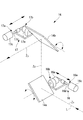
本実施形態に係る多光子励起型観察装置1は、多光子励起型顕微鏡であって、図1に示されるように、光源装置(多光子励起型観察用光源装置)2と、該光源装置2の後段に配置される蛍光顕微鏡本体(観察装置本体)3とを備えている。
Hereinafter, a multiphoton excitation observation apparatus according to an embodiment of the present invention will be described with reference to FIGS.
The multiphoton excitation type observation apparatus 1 according to the present embodiment is a multiphoton excitation type microscope, and as shown in FIG. 1, a light source device (multiphoton excitation type light source device for observation) 2 and the light source device 2. And a fluorescence microscope main body (observation apparatus main body) 3 disposed in the latter stage.
前記光源装置2は、異なる波長の極短パルスレーザ光Lを出射可能な波長可変のパルスレーザ光源4と、該パルスレーザ光源4から発せられる極短パルスレーザ光Lの群速度分散を補償する分散補償光学系5と、分散補償された極短パルスレーザ光Lのオンオフあるいは強度変調する音響光学装置6と、該音響光学装置6とパルスレーザ光源4との間に配置され、音響光学装置6に入射させる極短パルスレーザ光Lを調節する入射補正装置7と、音響光学装置6から出射され、前記蛍光顕微鏡本体3に入射される極短パルスレーザ光Lを調節する顕微鏡入射補正装置8と、これらを制御する制御装置9とを備えている。
The light source device 2 includes a tunable pulsed laser light source 4 capable of emitting ultrashort pulsed laser light L having different wavelengths, and a dispersion for compensating for group velocity dispersion of the ultrashort pulsed laser light L emitted from the pulsed laser light source 4. The
前記分散補償光学系5は、例えば、一対のプリズム10,11とミラー12とから構成されている。図2に示されるように、プリズム10,11どうしの間隔を調節することで、波長ごとに分散補償量を調節して、パルスレーザ光源4から蛍光顕微鏡本体3の対物レンズ3aに至る全光学系における群速度分散を補償するようになっている。この際に、光路長の調節により、光軸がシフトし、波長の変化によって光軸の角度が変動するので、プリズム10,11およびミラー12の位置および角度を矢印に示すように調節することにより、出射される極短パルスレーザ光Lの光軸の位置および角度が調節されるようになっている。
図中、符号13は、パルスレーザ光源4から発せられた極短パルスレーザ光Lを反射して分散補償光学系5に指向させる一方、分散補償光学系5から出力された極短パルスレーザ光Lの光軸から外れた位置に配置されているミラーである。
The dispersion compensation
In the figure,
前記入射補正装置7は、アライメント調節装置14とビーム整形光学系15とを備えている。
前記アライメント調節装置14は、図3に示されるように、例えば、2枚のミラー14a,14bとこれらミラー14a,14bをそれぞれ移動させる2つのミラー移動機構16,17とを備えている。第1のミラー14aは、第1の方向Z1から矢印のように入射されてきた極短パルスレーザ光Lを、該第1の方向Z1に略直交する第2の方向Z2に偏向させるようになっている。また、第2のミラー14bは、第2の方向Z2に入射される極短パルスレーザ光Lを、第1の方向Z1および第2の方向Z2に略直交する第3の方向Z3に偏向させて出射するようになっている。
The
As shown in FIG. 3, the
第1のミラー移動機構16は、前記第1の方向Z1に沿って第1のミラー14aを並進移動させる第1の並進機構16aと、前記第3の方向Z3に平行な軸線回りに第1のミラー14aを揺動させる第1の揺動機構16bとを備えている。第2のミラー移動機構17は、前記第3の方向に沿って第2のミラー14bを並進移動させる第2の並進機構17aと、前記第1の方向Z1に平行な軸線回りに第2のミラー14bを揺動させる第2の揺動機構17bとを備えている。第1、第2の並進機構16a,17aは、例えば、モータ16c,17cおよびボールネジ16d,17dにより駆動され、第1、第2の揺動機構16b,17bは、例えば、モータ16e,17eにより構成されている。
The first
これにより、極短パルスレーザ光Lの光軸の角度が、第1の方向Z1に対して、第1の方向Z1および第2の方向Z2を含む平面内においてずれている場合には、第1の揺動機構16bを作動させてその角度を調節し、第1の方向Z1に対して第2の方向Z2および第3の方向Z3を含む平面内においてずれている場合には、第2の揺動機構17bを作動させてその角度を調節することができるようになっている。また、アライメント調節装置14から出射される極短パルスレーザ光Lの光軸の位置が第1の方向Z1にずれている場合には、第1の並進機構16aを作動させ、第2の方向Z2にずれている場合には第2の並進機構17aを作動させて、その位置ずれを調節することができるようになっている。
Thus, if the angle of the optical axis of the ultrashort pulsed laser light L with respect to the first direction Z 1, it is shifted in the plane including the first direction Z 1 and a second direction Z 2 is actuates a first
これにより、アライメント調節装置14から出射される極短パルスレーザ光Lは、入射される極短パルスレーザ光Lの光軸の角度および位置の如何にかかわらず、その光軸の角度および位置を精度よく一定の位置に調節することができるようなっている。
As a result, the ultrashort pulse laser beam L emitted from the
また、ビーム整形光学系15は、分散補償光学系5を通過し、アライメント調節装置14によって位置合わせされた極短パルスレーザ光Lの光束径を絞り、音響光学装置6の結晶18(図4参照)の有効範囲X内に漏れなく入射させるように構成されている。
本実施形態においては、ビーム整形光学系15は、例えば、図4に示されるように、両凸レンズ19と平凹レンズ20とを組み合わせたガリレイ型のビームエキスパンダと、両凸レンズ19および平凹レンズ20をそれぞれ光軸方向に移動可能に支持するレンズ移動機構21,22とにより構成されている。また、ビーム整形光学系15は、パルスレーザ光源4と音響光学装置6との間に、その中央よりも音響光学装置6側に配置されていることが好ましい。また、ビーム整形光学系15は、音響光学装置6の100〜1000mmの位置に配置されていることがさらに好ましい。
Further, the beam shaping
In the present embodiment, the beam shaping
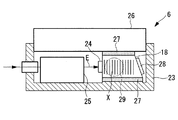
前記音響光学装置6は、図4〜図6に示されるように、例えば、AOMであって、2酸化テルルからなる結晶18と、該結晶18を固定するケース23と、結晶18に接着された圧電素子からなるトランスデューサ24と、該トランスデューサ24に入力する電気信号Eを伝達する音響波発生用電気回路25と、前記結晶18に接着されたヒートシンク(放熱部材)26とを備えている。結晶18とケース23との間、結晶18とヒートシンク26との間には、例えば、シリコーングリースのようなサーマルコンパウンドあるいはインジウム箔からなる界面材27が介在させられている。また、図6中、符号28は、トランスデューサ24から発せられ、結晶18内を伝播した音響波を吸収する吸音材である。
As shown in FIGS. 4 to 6, the
結晶18を挟んで対向するケース23の一対の側壁にはそれぞれ開口部29が設けられており、一の開口部29から極短パルスレーザ光Lを入射させ、結晶18を通過した極短パルスレーザ光Lを他の開口部29から出射させるようになっている。
前記ヒートシンク26は、例えば、アルミニウムあるいはアルミニウム合金のような熱伝導率の高い材質からなり、図5に示されるように、平行間隔をあけて配置される複数の平板状のフィン26aを備えている。
An
The
前記顕微鏡入射補正装置8は、アライメント調節装置30と、視準光学系31とを備えている。
アライメント調節装置30は、例えば、図3に示されるアライメント調節装置14と同一構造を有し、蛍光顕微鏡本体3に入射させる極短パルスレーザ光Lの光軸の位置と偏向を精度よく調節することができるようになっている。
The microscope
The
また、視準光学系31は、例えば、図4に示されるビーム整形光学系15と同一構造を有し、極短パルスレーザ光Lが、蛍光顕微鏡本体3の対物レンズ3aの瞳位置に瞳径と略同等の光束径で入射されるように、出射される極短パルスレーザ光Lの光束径およびビームダイバージェンスを調節することができるようになっている。
The collimating
極短パルスレーザ光Lは、光束径W、波面の曲率RおよびビームダイバージェンスDがW=R・Dとなる関係を有している。これら3つの変数W,R,Dはいずれも極短パルスレーザ光Lの波長λ、ビームウエスト位置における光束径W0およびビームウエスト位置からの光軸方向距離の関数である。したがって、これら3つの変数W,R,Dのうち、いずれか2つを決定することにより、極短パルスレーザ光Lを一意に決定することができる。すなわち、光束径WとビームダイバージェンスDとを調節することは、光束径Wと波面の曲率Rとを調節すること、および、波面の曲率RとビームダイバージェンスDとを調節することと等価である。 The ultrashort pulse laser beam L has a relationship in which the beam diameter W, the wavefront curvature R, and the beam divergence D are W = R · D. These three variables W, R, and D are all functions of the wavelength λ of the ultrashort pulse laser beam L, the beam diameter W 0 at the beam waist position, and the optical axis direction distance from the beam waist position. Therefore, by determining any two of these three variables W, R, and D, the ultrashort pulse laser beam L can be uniquely determined. That is, adjusting the light beam diameter W and the beam divergence D is equivalent to adjusting the light beam diameter W and the wavefront curvature R, and adjusting the wavefront curvature R and the beam divergence D.
前記制御装置9には、パルスレーザ光源4から出射される極短パルスレーザ光Lの波長λとその波長λが選択されたときの前記各調節装置(分散補償光学系5、アライメント調節装置14,30、ビーム整形光学系15、視準光学系31および音響光学装置6)の最適な作動状態Y、例えば、分散補償光学系5のプリズム10,11の位置および角度、アライメント調節装置14,30のミラー移動機構16,17の移動位置、ビーム整形光学系15および視準光学系31を構成するレンズ移動機構21,22の移動位置、音響光学装置6のトランスデューサ24により結晶18に入力する音響波の周波数等とを対応づけて記憶するメモリ装置32が備えられている。各調節装置の作動状態Yは相互に関連している場合があるので、全ての調節装置に対して、波長λと作動状態Yとが設定されていることが好ましい。
The control device 9 includes a wavelength λ of the ultrashort pulse laser light L emitted from the pulse laser light source 4 and the adjustment devices (dispersion compensation
そして、パルスレーザ光源4から出射される極短パルスレーザ光Lの波長λが、例えば、パルスレーザ光源Lから出力される波長情報(あるいは、外部から入力される極短パルスレーザ光の波長情報)λによって取得されると、制御装置9は、取得された波長情報λに基づいてメモリ装置32内を検索し、波長λに対応する作動状態Yとなるように各調節装置を自動調節するようになっている。
The wavelength λ of the ultrashort pulse laser light L emitted from the pulse laser light source 4 is, for example, wavelength information output from the pulse laser light source L (or wavelength information of the ultrashort pulse laser light input from the outside). When acquired by λ, the control device 9 searches the
これにより、パルスレーザ光源4の波長λの変化にかかわらず、簡易かつ精度よく極短パルスレーザ光Lを漏れなく音響光学装置6の結晶18の有効範囲X内に通過させ、あるいは、対物レンズ3aの瞳位置に瞳径と略同等の極短パルスレーザ光Lを入射させて、試料Aにおける多光子励起効果を効率的に発生させることができるようになっている。
As a result, regardless of the change in the wavelength λ of the pulsed laser light source 4, the ultrashort pulsed laser light L can be passed through the effective range X of the
前記蛍光顕微鏡本体3は、極短パルスレーザ光Lを2次元的に走査する(例えば、近接ガルバノミラーのような)ガルバノミラー33、走査された極短パルスレーザ光Lを集光して中間像を結像させる瞳投影レンズ34、中間像を結像した極短パルスレーザ光Lを集光して略平行光にする結像レンズ35、略平行光にされた極短パルスレーザ光Lを集光して試料Aに結像させる対物レンズ3a、試料Aにおいて発せられ対物レンズ3aにより集光された多光子蛍光Fを極短パルスレーザ光Lから分岐するダイクロイックミラー36、分岐された多光子蛍光Fを集光する集光レンズ37、集光された多光子蛍光Fを検出する光電子増倍管(PMT)38とを備えている。符号39,40はミラーである。
The fluorescence microscope main body 3 scans the ultrashort pulse laser light L two-dimensionally (for example, a galvano mirror such as a proximity galvanometer mirror), condenses the scanned ultrashort pulse laser light L, and forms an intermediate image. An
このように構成された本実施形態に係る多光子励起型観察装置1の作用について、以下に説明する。
本実施形態に係る多光子励起型観察装置1によれば、パルスレーザ光源4から発せられる極短パルスレーザ光Lの波長が決定されると、その波長情報λがパルスレーザ光源4から、あるいは、外部の入力装置(図示略)から制御装置9に入力される。
制御装置9においては、入力された極短パルスレーザ光Lの波長情報λに基づいて、メモリ装置32内が検索され、その波長情報λに関連づけて記憶されている各調節装置の作動状態Yが取得される。制御装置9は、取得された作動状態Yとなるように各調節装置を制御する。
The operation of the thus configured multiphoton excitation observation apparatus 1 according to this embodiment will be described below.
According to the multiphoton excitation observation apparatus 1 according to the present embodiment, when the wavelength of the ultrashort pulse laser light L emitted from the pulse laser light source 4 is determined, the wavelength information λ is obtained from the pulse laser light source 4 or It is input to the control device 9 from an external input device (not shown).
In the control device 9, the
具体的には、まず、パルスレーザ光源4から出射される極短パルスレーザ光Lの波長λが決定されると、パルスレーザ光源4から出射される極短パルスレーザ光Lの多光子励起型観察装置1の光学系全体における群速度分散量が定まるので、その群速度分散を補償するような分散補償量となる作動状態Yに分散補償光学系5が制御される。分散補償光学系5においては、2つのプリズム10,11間の距離および2つのプリズム10,11の角度およびミラー12の位置が制御装置9により指示される作動状態Yとなるように制御される。これにより、適正に分散補償された極短パルスレーザ光Lが分散補償光学系5から出力される。
Specifically, first, when the wavelength λ of the ultrashort pulse laser light L emitted from the pulse laser light source 4 is determined, the multiphoton excitation type observation of the ultrashort pulse laser light L emitted from the pulse laser light source 4 is performed. Since the group velocity dispersion amount in the entire optical system of the apparatus 1 is determined, the dispersion compensation
次に、パルスレーザ光源4から出射される極短パルスレーザ光Lの波長λが決定されると、パルスレーザ光源4からの出射方向および分散補償光学系5から出射方向が決定される。したがって、制御装置9は、メモリ装置32から取得したミラー移動機構16,17の作動状態Yとなるようにアライメント調節装置14を制御して、ビーム整形光学系15に入射される極短パルスレーザ光Lの光軸の位置および角度が、極短パルスレーザ光Lの波長λの如何にかかわらず一定となるように調節する。
Next, when the wavelength λ of the ultrashort pulse laser beam L emitted from the pulse laser light source 4 is determined, the emission direction from the pulse laser light source 4 and the emission direction from the dispersion compensation
また、パルスレーザ光源4から出射される極短パルスレーザ光Lの波長λが決定されると、分散補償光学系5から出力される極短パルスレーザ光Lのビームウエスト位置およびビームダイバージェンスが決定される。したがって、制御装置9は、メモリ装置32から取得したレンズ移動機構21,22の作動状態Yとなるようにビーム整形光学系15を制御して、出射される極短パルスレーザ光Lの光束径を調節する。
When the wavelength λ of the ultrashort pulse laser beam L emitted from the pulse laser light source 4 is determined, the beam waist position and beam divergence of the ultrashort pulse laser beam L output from the dispersion compensation
この場合において、ビーム整形光学系15は、極短パルスレーザ光Lの光束径を縮小して、音響光学装置6の結晶18の有効範囲X内に入射させるように構成されているので、極短パルスレーザ光Lが漏れなく結晶18を通過させられる。
In this case, the beam shaping
また、パルスレーザ光源4から出射される極短パルスレーザ光Lの波長λが決定されると、音響光学装置6からの変調後の極短パルスレーザ光Lの出射方向が所定の方向となるような音響波の周波数が決定される。したがって、制御装置9は、メモリ装置32から取得した音響波発生用電気回路25の作動状態Yとなるように音響光学装置6を制御して、オンオフあるいは出力調節された極短パルスレーザ光Lを所定の方向に出力させる。
Further, when the wavelength λ of the ultrashort pulse laser light L emitted from the pulse laser light source 4 is determined, the emission direction of the ultrashort pulse laser light L after modulation from the
音響光学装置6においては、音響波発生用電気回路25の作動により、所定周波数の電気信号Eがトランスデューサ24に入力され、トランスデューサ24において発生させられた音響波によって、結晶18内における極短パルスレーザ光Lの音響光学効果が発生する。また、トランスデューサ24により発生する音響波の振幅を変更することにより、結晶18内における極短パルスレーザ光Lの回折強度を変化させ、音響光学装置6から出射される極短パルスレーザ光Lの強度を、音響波の振幅に応じた所定の割合で変調する。
In the
これにより、入射された極短パルスレーザ光Lが結晶18を通過してケース23の開口部29から、所定の強度に変調された状態で出射されることになる。
この場合において、ビーム整形光学系15によって極短パルスレーザ光Lが結晶18の有効範囲X内に漏れなく入射されているので、結晶18に入射されない極短パルスレーザ光Lや結晶18の側面によって乱反射等される極短パルスレーザ光Lが存在しない。したがって、これらの極短パルスレーザ光Lが迷光となって、正常に結晶18を通過する極短パルスレーザ光Lに混入することがない。
As a result, the incident ultrashort pulse laser beam L passes through the
In this case, since the ultrashort pulse laser beam L is incident on the
その結果、結晶18から出射される極短パルスレーザ光Lにおける波面の乱れの発生が抑制され、試料Aの集光位置におけるPSFの悪化が抑制される。すなわち、対物レンズ3aの前方に形成される試料Aにおける集光位置において、光子密度の低下が防止され、多光子励起効果を効率的に発生させることが可能となる。
As a result, the occurrence of wavefront disturbance in the ultrashort pulse laser beam L emitted from the
また、トランスデューサ24により結晶18に入力する音響波をオンオフすることにより、極短パルスレーザ光Lの出射と遮断とを切り替えてオンオフすることができる。例えば、蛍光顕微鏡本体3のガルバノミラー33による極短パルスレーザ光Lの2次元的な走査と同期させて極短パルスレーザ光Lをオンオフすることにより、試料Aに対して所定の走査範囲のみに極短パルスレーザ光Lを照射することが可能となる。
Further, by turning on and off the acoustic wave input to the
また、極短パルスレーザ光Lは音響光学装置6の結晶18内を通過させられる際に音響光学効果によって回折させられる。このとき、結晶18にはトランスデューサ24から音響波が入力されるので、そのエネルギによって結晶18が局所的に発熱する。
The ultrashort pulse laser beam L is diffracted by the acoustooptic effect when it passes through the
本実施形態に係る多光子励起型観察装置1によれば、結晶18自体の熱容量が小さいが、該結晶18に熱容量の大きなヒートシンク26が接着されているので、結晶18において発生した熱はヒートシンク26によって吸収される。また、ヒートシンク26には複数のフィン26aが設けられているので、結晶18から吸収した熱は、これらのフィン26aを介して外気に効率的に放散される。これにより、結晶18の局所的な温度上昇が抑制され、結晶18内の屈折率の変動が大幅に抑制されることになる。
According to the multiphoton excitation observation apparatus 1 according to this embodiment, the heat capacity of the
結晶18の屈折率が変動すると、結晶18内における極短パルスレーザ光Lの回折が変化するため、音響光学装置6からの出射方向が変化する。したがって、何ら対策を施さない場合には、アライメント調節装置14,30によって極短パルスレーザ光Lの光軸の位置と偏向を厳密に調節しておいても、トランスデューサ24から入力される音響波によって、結晶18の温度が経時的に変化し、それによって結晶18からの出射方向がずれて適正な位置に出射されなくなってしまうことになる。
When the refractive index of the
また、結晶18に入力する音響波の振幅は、その強度変調の程度やオンオフの頻度等の使用状態によって相違するため、使用状態ごとに極短パルスレーザ光Lの出射方向が変化する。
特に、AOMの場合には、音響波を発生させるためにトランスデューサ24に入力する駆動電力が高いこと、および、極短パルスレーザ光Lを入射させる有効範囲の面積が小さいことにより、対策を施さない場合には結晶18内は局所的に加熱される。
Further, since the amplitude of the acoustic wave input to the
In particular, in the case of AOM, no countermeasure is taken due to the high driving power input to the
本実施形態によれば、熱容量の大きなヒートシンク26によって結晶18の温度変化が抑制されるので、音響波を発生させるためにトランスデューサ24に入力する駆動電力が高くても、結晶18における局所的な加熱状態が防止され、極短パルスレーザ光Lの出射方向を一定に維持することができる。その結果、結晶18の経時的な温度変化を検出したり、検出された結晶18の温度に基づいてアライメント調節装置30をその都度調節したりする必要がなく、簡易な構成で、観察開始時に設定されたアライメント状態のままで、試料Aの適正な照射範囲に極短パルスレーザ光Lを照射して、蛍光観察を行うことができる。
なお、本実施形態においては、ヒートシンク26の形態として、平板状のフィン26aを備えるものを例示したが、これに代えて、他の任意の形態のヒートシンク26を採用することができる。
According to this embodiment, since the temperature change of the
In the present embodiment, as the form of the
また、パルスレーザ光源4から出射される極短パルスレーザ光Lの波長λが決定されると、音響光学装置6から極短パルスレーザ光Lの出射方向が決定される。したがって、制御装置9は、メモリ装置32から取得したミラー移動機構16,17の作動状態Yとなるようにアライメント調節装置30を制御して、視準光学系31に入射される極短パルスレーザ光Lの光軸の位置および角度が、極短パルスレーザ光Lの波長λの如何にかかわらず一定となるように調節する。
When the wavelength λ of the ultrashort pulse laser beam L emitted from the pulse laser light source 4 is determined, the emission direction of the ultrashort pulse laser beam L from the
また、パルスレーザ光源4から出射される極短パルスレーザ光Lの波長λが決定されると、音響光学装置6から出力される極短パルスレーザ光Lのビームウエスト位置およびビームダイバージェンスが決定される。したがって、制御装置9は、メモリ装置32から取得したレンズ移動機構21,22の作動状態Yとなるように視準光学系31を制御して、出射される極短パルスレーザ光Lの光束径およびビームダイバージェンスを調節する。
When the wavelength λ of the ultrashort pulse laser light L emitted from the pulse laser light source 4 is determined, the beam waist position and beam divergence of the ultrashort pulse laser light L output from the
視準光学系31においては、パルスレーザ光源4から発せられ、分散補償光学系5、アライメント調節装置14、ビーム整形光学系15、音響光学装置6およびアライメント調節装置30を通過してきた極短パルスレーザ光Lの光束径およびビームダイバージェンスを再度補正し直すことにより、蛍光顕微鏡本体3の対物レンズ3aの瞳位置に、その瞳径と略同等の光束径を有するように補正する。これにより、パルスレーザ光源4から発せられた極短パルスレーザ光Lを最も無駄なく効率的に試料Aに集光させ、試料A内に形成されるビームウエスト位置における光子密度を向上させて、効率的に多光子励起効果を発生させることができる。
In the collimation
このように、本実施形態に係る多光子励起型観察装置1および多光子励起型観察用光源装置2によれば、パルスレーザ光源4から出射される極短パルスレーザ光Lの波長λが変更されても、制御装置9が、その波長情報λに基づいて各調節装置を制御する。したがって、極短パルスレーザ光Lの波長λが変更されても、蛍光顕微鏡本体3の対物レンズ3aの瞳位置に、その瞳径と略同等の光束径を有する極短パルスレーザ光Lを入射させることができ、試料Aにおける多光子励起効果を効率的に発生させて鮮明な多光子励起画像を得ることができるという効果を奏する。
Thus, according to the multiphoton excitation observation apparatus 1 and the multiphoton excitation observation light source apparatus 2 according to the present embodiment, the wavelength λ of the ultrashort pulse laser light L emitted from the pulse laser light source 4 is changed. However, the control device 9 controls each adjusting device based on the wavelength information λ. Therefore, even if the wavelength λ of the ultrashort pulse laser beam L is changed, the ultrashort pulse laser beam L having a beam diameter substantially equal to the pupil diameter is made incident on the pupil position of the
また、波長の変更等が生じても、極短パルスレーザ光Lのビームウエスト位置が光軸方向にずれるのを防止でき、波長にかかわらず、試料Aの同一位置にピントを合わせることができる。
さらに、制御装置9は、メモリ装置32に波長λと対応づけて記憶されている各調節装置の作動状態Yによって各調節装置を制御する。したがって、波長λが変更されても、簡易かつ迅速に、試料Aにおいて多光子励起効果を効率的に発生させるように極短パルスレーザ光Lを調節することができる。
Even if the wavelength is changed, the beam waist position of the ultrashort pulse laser beam L can be prevented from being shifted in the optical axis direction, and the same position of the sample A can be focused regardless of the wavelength.
Further, the control device 9 controls each adjusting device according to the operating state Y of each adjusting device stored in the
なお、本実施形態に係る多光子励起型観察用光源装置においては、分散補償光学系5として、2つのプリズム10,11とミラー12とを有する構造のものを採用したが、これに代えて、グレーティング対により構成されていてもよい。この場合、グレーティングどうしの間隔を調節することにより、波長ごとに分散補償量を調節して、パルスレーザ光源4から蛍光顕微鏡本体3の対物レンズ3aに至る全光学系における群速度分散を補償することができる。
また、プリズム10,11およびミラー12の組合せの他、複数のプリズムの組合せ、複数のグレーティングの組合せ、プリズムとグレーティングとの組合せからなる分散補償光学系を採用することにしてもよい。
In the multi-photon excitation observation light source device according to the present embodiment, the dispersion compensation
In addition to the combination of the
また、本実施形態においては、波長λと作動状態Yとを予め関連づけてメモリ装置32に記憶しておくこととしたが、これに代えて、極短パルスレーザ光Lのアライメント状態を測定し、その測定結果をフィードバックしてアライメント調節装置14,30を制御することにしてもよい。このようにすることで、波長λが連続的に変化する場合においても極短パルスレーザ光の光軸の位置および方向が一定となるように調節することができる。
In the present embodiment, the wavelength λ and the operating state Y are associated with each other in advance and stored in the
また、ビーム整形光学系15に入力される極短パルスレーザ光Lあるいはビーム整形光学系15から出力される極短パルスレーザ光Lの光束径を測定し、その測定結果に基づいて、所定の光束径やビームダイバージェンスが達成できるようにレンズ移動機構21,22を自動調節することにしてもよい。また、波長λの変更により生ずるビームウエスト位置の移動、ビームダイバージェンスの変動を検出し、それぞれ所望のビームウエスト位置およびビームダイバージェンスが達成できるように各調節装置を自動調節することにしてもよい。
Further, the beam diameter of the ultrashort pulse laser beam L input to the beam shaping
また、本実施形態に係る多光子励起型観察装置1および多光子励起型観察用光源装置2においては、ガリレイ型のビーム整形光学系15および視準光学系31を採用したが、これに代えて、複数の凸レンズを有するケプラー型のビーム整形光学系15および視準光学系31を採用してもよい。
また、ビーム整形光学系15は、図7に示されるように、一対の凹面鏡41,42を対向配置することにより構成してもよい。このように構成することで反射光学系によって極短パルスレーザ光Lの光束径を縮小させるので、ビーム整形光学系15を通過する際に群速度分散を生じることがなく、パルス幅が広がることを防止できる。
In the multiphoton excitation observation device 1 and the multiphoton excitation observation light source device 2 according to the present embodiment, the Galilean beam shaping
Further, the beam shaping
また、図8に示すように、ビーム整形光学系15として、絞り43(あるいはスリットまたはピンホール等の空間フィルタ)を採用してもよい。このようにすることで、簡易な構成により極短パルスレーザ光Lの光束径を縮小させることができ、また調節も簡単であるという利点がある。
Further, as shown in FIG. 8, a diaphragm 43 (or a spatial filter such as a slit or a pinhole) may be employed as the beam shaping
また、ビーム整形光学系15および視準光学系31が、2以上のレンズにより構成される場合には、レンズ移動機構はその少なくとも1つのレンズを光軸方向に移動させるように構成されていればよい。
Further, when the beam shaping
さらに、極短パルスレーザ光Lの採用し得る波長λが有限個に限られる場合には、図9に示されるように、各波長λに適合する距離や角度に予め調節された状態に固定されたレンズ群あるいは凹面鏡からなる複数の補正光学ユニット15A,15B,15Cと、該補正光学ユニット15A,15B,15Cを切り替える切替機構44とを備えるものとしてもよい。この場合においても、波長λと補正光学ユニット15A,15B,15Cとを対応づけてメモリ装置32に記憶しておき、得られた波長情報λに基づいてメモリ装置32内を検索して対応する補正光学ユニット15A,15B,15Cを選択し、切替機構44により切り替えることとすれば、上記と同様に、簡易に高精度の多光子蛍光画像を取得することが可能となる。
Furthermore, when the wavelength λ that can be used by the ultrashort pulse laser beam L is limited to a finite number, as shown in FIG. 9, the wavelength λ is fixed in a state adjusted in advance to a distance and angle suitable for each wavelength λ. A plurality of correction
なお、視準光学系31についても同様の構造を採用することができる。また、この構造を採用するビーム整形光学系15および視準光学系31において、補正光学ユニット15A〜15Cについては、その数は2以上でよい。
また、視準光学系31,ビーム整形光学系15のレンズ構成は、いずれも図示のような両凸レンズと平凹レンズとの組合せに限られるものではなく、正または負のパワーを持つ任意のレンズの組合せにより構成されるものであってもよい。
A similar structure can be employed for the collimating
Further, the lens configurations of the collimating
A 試料
F 蛍光
L 極短パルスレーザ光
λ 波長
X 有効範囲
Y 作動状態
1 多光子励起型観察装置
2 多光子励起型観察用光源装置
3 蛍光顕微鏡本体(観察装置本体)
3a 対物レンズ
4 パルスレーザ光源
5 分散補償光学系(分散補償装置)
7 入射補正装置
8 顕微鏡入射調節装置(入射調節装置)
9 制御装置
14 アライメント調節装置(入射側アライメント調節装置)
14a,14b ミラー
16,17 ミラー移動機構
21,22 レンズ移動機構
30 アライメント調節装置(出射側アライメント調節装置)
31 視準光学系(入射調節装置)
32 メモリ装置
A Sample F Fluorescence L Ultrashort pulse laser light λ Wavelength X Effective range Y Operating state 1 Multiphoton excitation type observation device 2 Multiphoton excitation type light source device 3 Fluorescence microscope main body (observation apparatus main body)
3a Objective lens 4 Pulsed
7
9
14a,
31 Collimation optics (incident adjustment device)
32 Memory device
Claims (11)
該パルスレーザ光源から発せられた極短パルスレーザ光を試料に照射し、試料において発せられた蛍光を観察する観察装置本体と、
前記パルスレーザ光源と観察装置本体との間に配置され、パルスレーザ光源から発せられる極短パルスレーザ光のオンオフあるいは出力調整を行う音響光学装置と、
該音響光学装置と前記パルスレーザ光源との間に配置され、音響光学装置に入射される極短パルスレーザ光の光軸の位置および角度を変更可能にする入射側アライメント調節装置と、
前記パルスレーザ光源から出射される極短パルスレーザ光の波長に基づいて、前記入射側アライメント調節装置を制御する制御装置とを備える多光子励起型観察装置。 A pulsed laser light source capable of emitting ultrashort pulsed laser light of different wavelengths;
An observation apparatus main body for irradiating the sample with an ultrashort pulse laser beam emitted from the pulse laser light source and observing fluorescence emitted from the sample;
An acousto-optic device that is disposed between the pulse laser light source and the observation device main body and performs on / off or output adjustment of the ultrashort pulse laser light emitted from the pulse laser light source;
An incident-side alignment adjusting device that is disposed between the acousto-optic device and the pulsed laser light source and that can change the position and angle of the optical axis of the ultrashort pulsed laser light incident on the acousto-optic device;
A multiphoton excitation observation apparatus comprising: a control device that controls the incident-side alignment adjustment device based on a wavelength of an ultrashort pulse laser beam emitted from the pulse laser light source.
前記制御装置が、前記パルスレーザ光源から出射される極短パルスレーザ光の波長に基づいて、前記出射側アライメント調節装置を制御する請求項1に記載の多光子励起型観察装置。 An emission-side alignment adjusting device that is disposed between the acoustooptic device and the observation device main body and that can change the position and angle of the optical axis of the ultrashort pulse laser beam emitted from the acoustooptic device;
The multi-photon excitation observation device according to claim 1, wherein the control device controls the emission side alignment adjusting device based on a wavelength of an ultrashort pulse laser beam emitted from the pulse laser light source.
前記制御装置が、前記極短パルスレーザ光の波長に応じて、前記分散補償装置による分散補償量を調節する請求項1から請求項6のいずれかに記載の多光子励起型観察装置。 A dispersion compensator for compensating for group velocity dispersion is provided,
The multi-photon excitation observation device according to any one of claims 1 to 6, wherein the control device adjusts a dispersion compensation amount by the dispersion compensation device according to a wavelength of the ultrashort pulse laser beam.
該入射補正装置が、複数のレンズと、該レンズのうち少なくとも1枚のレンズを光軸方向に移動させるレンズ移動機構とを備え、
前記制御装置が、前記極短パルスレーザ光の波長に応じて前記レンズ移動機構を作動させる請求項4から請求項7のいずれかに記載の多光子励起型観察装置。 An incident correction device that is disposed between the acoustooptic device and the incident-side alignment adjustment device and reduces the beam diameter of the ultrashort pulse laser beam so that the beam diameter can be incident within the effective range of the acoustooptic device;
The incident correction device includes a plurality of lenses and a lens moving mechanism that moves at least one of the lenses in the optical axis direction;
The multi-photon excitation observation apparatus according to any one of claims 4 to 7, wherein the control device operates the lens moving mechanism in accordance with a wavelength of the ultrashort pulse laser beam.
該入射調節装置が、複数のレンズと、該レンズのうち少なくとも1枚のレンズを光軸方向に移動させるレンズ移動機構とを備え、
前記制御装置が、前記極短パルスレーザ光の波長に応じて前記レンズ移動機構を作動させる請求項1から請求項8のいずれかに記載の多光子励起型観察装置。 It is arranged between the emission side alignment adjusting device and the observation device main body, and includes an incident adjusting device that adjusts the beam diameter and beam divergence of the ultrashort pulse laser beam,
The incident adjustment device includes a plurality of lenses and a lens moving mechanism that moves at least one of the lenses in the optical axis direction,
The multiphoton excitation observation apparatus according to any one of claims 1 to 8, wherein the control device operates the lens moving mechanism in accordance with a wavelength of the ultrashort pulse laser beam.
前記パルスレーザ光源から発せられる極短パルスレーザ光のオンオフあるいは出力調整を行う音響光学装置と、
該音響光学装置と前記パルスレーザ光源との間に配置され、音響光学装置に入射される極短パルスレーザ光の光軸の位置および角度を調節する入射側アライメント調節装置と、
前記パルスレーザ光源から出射される極短パルスレーザ光の波長に基づいて、前記入射側アライメント調節装置を制御する制御装置とを備える多光子励起型観察用光源装置。 A pulsed laser light source capable of emitting ultrashort pulsed laser light of different wavelengths;
An acousto-optic device that performs on / off or output adjustment of an ultrashort pulse laser beam emitted from the pulse laser light source;
An incident-side alignment adjusting device that is arranged between the acoustooptic device and the pulse laser light source and adjusts the position and angle of the optical axis of the ultrashort pulse laser beam incident on the acoustooptic device;
A multiphoton excitation observation light source device comprising: a control device that controls the incident-side alignment adjusting device based on the wavelength of the ultrashort pulse laser light emitted from the pulse laser light source.
前記制御装置が、前記パルスレーザ光源から出射される極短パルスレーザ光の波長に基づいて、前記出射側アライメント調節装置を制御する請求項10に記載の多光子励起型観察用光源装置。 An emission-side alignment adjusting device that is arranged at a subsequent stage of the acoustooptic device and adjusts the position and angle of the optical axis of the ultrashort pulse laser beam emitted from the acoustooptic device,
The multi-photon excitation observation light source device according to claim 10, wherein the control device controls the emission side alignment adjusting device based on a wavelength of an ultrashort pulse laser beam emitted from the pulse laser light source.
Priority Applications (1)
| Application Number | Priority Date | Filing Date | Title |
|---|---|---|---|
| JP2005098425A JP2006275917A (en) | 2005-03-30 | 2005-03-30 | Multiphoton excitation type observation device and light source device for multiphoton excitation type observation |
Applications Claiming Priority (1)
| Application Number | Priority Date | Filing Date | Title |
|---|---|---|---|
| JP2005098425A JP2006275917A (en) | 2005-03-30 | 2005-03-30 | Multiphoton excitation type observation device and light source device for multiphoton excitation type observation |
Publications (2)
| Publication Number | Publication Date |
|---|---|
| JP2006275917A true JP2006275917A (en) | 2006-10-12 |
| JP2006275917A5 JP2006275917A5 (en) | 2008-05-15 |
Family
ID=37210830
Family Applications (1)
| Application Number | Title | Priority Date | Filing Date |
|---|---|---|---|
| JP2005098425A Pending JP2006275917A (en) | 2005-03-30 | 2005-03-30 | Multiphoton excitation type observation device and light source device for multiphoton excitation type observation |
Country Status (1)
| Country | Link |
|---|---|
| JP (1) | JP2006275917A (en) |
Cited By (4)
| Publication number | Priority date | Publication date | Assignee | Title |
|---|---|---|---|---|
| JP2008292994A (en) * | 2007-04-23 | 2008-12-04 | Olympus Corp | Laser microscope |
| JP2009116280A (en) * | 2007-11-09 | 2009-05-28 | Olympus Corp | Optical device and laser microscope |
| JP2010096813A (en) * | 2008-10-14 | 2010-04-30 | Nikon Corp | Nonlinear optical microscope and method for adjusting same |
| JP2014089320A (en) * | 2012-10-30 | 2014-05-15 | Olympus Corp | Microscope device |
Citations (9)
| Publication number | Priority date | Publication date | Assignee | Title |
|---|---|---|---|---|
| JPH01282515A (en) * | 1988-05-10 | 1989-11-14 | Tokyo Electron Ltd | Beam scanning type optical microscope |
| JPH10122959A (en) * | 1996-08-30 | 1998-05-15 | Kdk Corp | Spectral light source device using acoustooptical element |
| JPH10206742A (en) * | 1996-11-21 | 1998-08-07 | Olympus Optical Co Ltd | Laser scanning microscope |
| JP2000330082A (en) * | 1999-05-19 | 2000-11-30 | Advantest Corp | Optical pulse generator |
| JP2002139436A (en) * | 1995-09-19 | 2002-05-17 | Cornell Research Foundation Inc | Multiphoton laser microscopic method |
| JP2003227796A (en) * | 2001-10-09 | 2003-08-15 | Carl Zeiss Jena Gmbh | Method and arrangement for grasping sample by depth decomposition |
| JP2003322799A (en) * | 2002-04-30 | 2003-11-14 | Olympus Optical Co Ltd | Laser microscope system |
| JP2004226777A (en) * | 2003-01-24 | 2004-08-12 | Optoquest Co Ltd | Automatic optical fiber coupling method of optical fiber transmission device for femto-second pulse laser light, and optical fiber transmission device for femto-second pulse laser light using the method |
| JP2004233710A (en) * | 2003-01-31 | 2004-08-19 | Advantest Corp | Optical module |
-
2005
- 2005-03-30 JP JP2005098425A patent/JP2006275917A/en active Pending
Patent Citations (9)
| Publication number | Priority date | Publication date | Assignee | Title |
|---|---|---|---|---|
| JPH01282515A (en) * | 1988-05-10 | 1989-11-14 | Tokyo Electron Ltd | Beam scanning type optical microscope |
| JP2002139436A (en) * | 1995-09-19 | 2002-05-17 | Cornell Research Foundation Inc | Multiphoton laser microscopic method |
| JPH10122959A (en) * | 1996-08-30 | 1998-05-15 | Kdk Corp | Spectral light source device using acoustooptical element |
| JPH10206742A (en) * | 1996-11-21 | 1998-08-07 | Olympus Optical Co Ltd | Laser scanning microscope |
| JP2000330082A (en) * | 1999-05-19 | 2000-11-30 | Advantest Corp | Optical pulse generator |
| JP2003227796A (en) * | 2001-10-09 | 2003-08-15 | Carl Zeiss Jena Gmbh | Method and arrangement for grasping sample by depth decomposition |
| JP2003322799A (en) * | 2002-04-30 | 2003-11-14 | Olympus Optical Co Ltd | Laser microscope system |
| JP2004226777A (en) * | 2003-01-24 | 2004-08-12 | Optoquest Co Ltd | Automatic optical fiber coupling method of optical fiber transmission device for femto-second pulse laser light, and optical fiber transmission device for femto-second pulse laser light using the method |
| JP2004233710A (en) * | 2003-01-31 | 2004-08-19 | Advantest Corp | Optical module |
Cited By (4)
| Publication number | Priority date | Publication date | Assignee | Title |
|---|---|---|---|---|
| JP2008292994A (en) * | 2007-04-23 | 2008-12-04 | Olympus Corp | Laser microscope |
| JP2009116280A (en) * | 2007-11-09 | 2009-05-28 | Olympus Corp | Optical device and laser microscope |
| JP2010096813A (en) * | 2008-10-14 | 2010-04-30 | Nikon Corp | Nonlinear optical microscope and method for adjusting same |
| JP2014089320A (en) * | 2012-10-30 | 2014-05-15 | Olympus Corp | Microscope device |
Similar Documents
| Publication | Publication Date | Title |
|---|---|---|
| JP4759425B2 (en) | Multiphoton excitation observation device | |
| JP4685489B2 (en) | Multiphoton excitation observation device | |
| JP6127090B2 (en) | Scanning device | |
| JP5241525B2 (en) | Laser processing equipment | |
| US7342219B2 (en) | Laser scanning microscope | |
| JP4693972B2 (en) | Laser microscope | |
| JP4640029B2 (en) | Wavelength conversion optical system, laser light source, exposure apparatus, specimen inspection apparatus, and polymer crystal processing apparatus | |
| JP2014525141A5 (en) | ||
| US7176428B2 (en) | Laser-based, multiphoton-excitation-type optical examination apparatus | |
| JP4922628B2 (en) | Scanning laser microscope | |
| JP5616824B2 (en) | Microscope equipment | |
| JP2007127524A (en) | Multiphoton excitation observation device and multiphoton excitation observing light source device | |
| JP5101393B2 (en) | Laser microscope | |
| EP2827180B1 (en) | Scanning optical microscope | |
| JP6419558B2 (en) | Observation device | |
| JP2006275917A (en) | Multiphoton excitation type observation device and light source device for multiphoton excitation type observation | |
| JP6648399B1 (en) | Laser processing apparatus, aberration adjustment method for laser processing apparatus, aberration control method for laser processing apparatus, and laser processing method | |
| JP4642525B2 (en) | Multiphoton excitation observation device | |
| JP2003347236A (en) | Laser irradiation device | |
| JP2007132794A (en) | Multiphoton excitation type observation device, and light source device for multiphoton excitation type observation | |
| JP5160372B2 (en) | Laser microscope equipment | |
| JP4878751B2 (en) | Microscope illumination device and fluorescence microscope device | |
| JP2012135807A (en) | Laser beam machining apparatus and laser beam machining method | |
| JP2023061087A (en) | Optical system and laser processing device | |
| JP2006226920A (en) | Multiphoton excitation type observation device, and light source device for multiphoton excitation type observation |
Legal Events
| Date | Code | Title | Description |
|---|---|---|---|
| A521 | Written amendment |
Free format text: JAPANESE INTERMEDIATE CODE: A523 Effective date: 20080327 |
|
| A621 | Written request for application examination |
Free format text: JAPANESE INTERMEDIATE CODE: A621 Effective date: 20080327 |
|
| A977 | Report on retrieval |
Free format text: JAPANESE INTERMEDIATE CODE: A971007 Effective date: 20100520 |
|
| A131 | Notification of reasons for refusal |
Free format text: JAPANESE INTERMEDIATE CODE: A131 Effective date: 20100525 |
|
| A02 | Decision of refusal |
Free format text: JAPANESE INTERMEDIATE CODE: A02 Effective date: 20100928 |