JP4685489B2 - Multiphoton excitation observation device - Google Patents
Multiphoton excitation observation device Download PDFInfo
- Publication number
- JP4685489B2 JP4685489B2 JP2005098423A JP2005098423A JP4685489B2 JP 4685489 B2 JP4685489 B2 JP 4685489B2 JP 2005098423 A JP2005098423 A JP 2005098423A JP 2005098423 A JP2005098423 A JP 2005098423A JP 4685489 B2 JP4685489 B2 JP 4685489B2
- Authority
- JP
- Japan
- Prior art keywords
- pulse laser
- laser light
- wavelength
- light source
- ultrashort pulse
- Prior art date
- Legal status (The legal status is an assumption and is not a legal conclusion. Google has not performed a legal analysis and makes no representation as to the accuracy of the status listed.)
- Expired - Fee Related
Links
Images


Description
本発明は、多光子励起型観察装置に関するものである。 The present invention relates to multiphoton-excitation observation equipment.
従来、生体等の試料にその表面から励起光を照射して、試料の表面下の比較的深い位置から発せられる蛍光を検出することにより、細胞等の機能を観察する装置として、多光子励起型の測定装置が知られている(例えば、特許文献1参照。)。
このような多光子励起型の観察装置に用いられる極短パルスレーザ光は、一般には略平行光であると考えられていても、厳密には光軸方向に沿う特定の位置に光束径が最も小さくなるビームウエストを備えるとともに、該ビームウエストの位置から離れるに従って、所定の広がり角度で光束径が大きくなるビームダイバージェンスを備えている。また、幾何光学的な考え方に基づいて、レンズの焦点距離等によって定まる焦点位置に集光し、その位置において最も光束径が小さくなると考えられているが、厳密には、極短パルスレーザ光の有するビームダイバージェンスによって定まるビームウエスト位置において最も光束径が小さくなる。
Although the ultrashort pulse laser beam used in such a multi-photon excitation type observation apparatus is generally considered to be substantially parallel light, strictly speaking, the beam diameter is the most at a specific position along the optical axis direction. It has a beam waist that decreases, and also has a beam divergence that increases the diameter of the light beam at a predetermined spread angle as it moves away from the position of the beam waist. Also, based on the geometric optical concept, it is considered that the light is condensed at the focal position determined by the focal length of the lens and the diameter of the light beam becomes the smallest at that position. The beam diameter becomes the smallest at the beam waist position determined by the beam divergence.
しかしながら、極短パルスレーザ光の光束径、ビームダイバージェンスおよびビームウエスト位置は、その極短パルスレーザ光を出射するパルスレーザ光源の個体差、パルスレーザ光源から発せられる極短パルスレーザ光の波長によって変動する。ビームウエスト位置が光軸方向に変動すると、試料において多光子励起効果が発生する位置が光軸方向に変動することになり、得られる多光子蛍光画像は試料の深さ方向に異なる位置の画像となるという不都合がある。特に、異なる複数の波長の極短パルスレーザ光を試料に照射して、各波長の極短パルスレーザ光によって励起される蛍光を観察する場合、波長毎に異なる深さ位置の多光子励起画像が取得されることとなるという問題がある。 However, the beam diameter, beam divergence, and beam waist position of the ultrashort pulse laser light vary depending on the individual difference of the pulse laser light source that emits the ultrashort pulse laser light and the wavelength of the ultrashort pulse laser light emitted from the pulse laser light source. To do. When the beam waist position fluctuates in the optical axis direction, the position where the multiphoton excitation effect occurs in the sample fluctuates in the optical axis direction, and the obtained multiphoton fluorescence image differs from the image at a position different in the sample depth direction. There is an inconvenience of becoming. In particular, when irradiating a sample with ultrashort pulse laser beams of a plurality of different wavelengths and observing fluorescence excited by the ultrashort pulse laser beams of each wavelength, multiphoton excitation images at different depth positions for each wavelength are obtained. There is a problem that it will be acquired.
この発明は上述した事情に鑑みてなされたものであって、極短パルスレーザ光を出射するパルスレーザ光源の個体差、パルスレーザ光源から発せられる極短パルスレーザ光の波長が変化しても、試料の同一深さ位置にビームウエストを配置することができる多光子励起型観察装置を提供することを目的としている。 This invention has been made in view of the above circumstances, and even if the individual difference of the pulse laser light source that emits the ultrashort pulse laser light, the wavelength of the ultrashort pulse laser light emitted from the pulse laser light source changes, and its object is to provide a multiphoton-excitation observation equipment which can be placed a beam waist at the same depth position of the sample.
上記目的を達成するために、本発明は以下の手段を提供する。
本発明は、波長可変な極短パルスレーザ光を出射するパルスレーザ光源と、該パルスレーザ光源から発せられた極短パルスレーザ光を試料に集光する対物レンズを有し、試料中の前記対物レンズの焦点位置において多光子励起により発せられた蛍光を観察する観察装置本体と、前記パルスレーザ光源と観察装置本体との間に配置され、パルスレーザ光源から発せられる極短パルスレーザ光の光束径およびビームダイバージェンスを調節する入射調節装置とを備え、前記パルスレーザ光源が、極短パルスレーザ光の波長を変化させることで、極短パルスレーザ光のビームダイバージェンス及び/又はビームウエスト位置を変化させ、前記入射調節装置が、前記パルスレーザ光源から出射される極短パルスレーザ光の波長に応じて、試料の同じ深さ位置にビームウエストが配置されるように、前記対物レンズに入射する極短パルスレーザ光のビームダイバージェンスを調整する多光子励起型観察装置を提供する。
In order to achieve the above object, the present invention provides the following means.
The present invention comprises a pulsed laser source for emitting a wavelength tunable ultrashort pulsed laser light, an objective lens which the ultrashort pulsed laser light emitted from said pulsed laser light source is focused on the sample, the objective of the sample An observation device body for observing fluorescence emitted by multiphoton excitation at the focal position of the lens, and a light beam diameter of an ultrashort pulse laser beam emitted between the pulse laser light source and the observation device body and emitted from the pulse laser light source And an incident adjustment device for adjusting beam divergence, wherein the pulse laser light source changes the beam divergence and / or beam waist position of the ultra-short pulse laser light by changing the wavelength of the ultra-short pulse laser light, The incidence adjusting device has the same depth of the sample according to the wavelength of the ultrashort pulse laser beam emitted from the pulse laser light source. As the beam waist is located at a position to provide a multiphoton-excitation observation apparatus for adjusting the beam divergence of the ultrashort pulsed laser beam incident on the objective lens.
本発明によれば、パルスレーザ光源から発せられた極短パルスレーザ光が観察装置本体に供給され、観察装置本体によって、試料に照射されると、試料における多光子励起効果によって、極短パルスレーザ光が集光させられた位置において多光子蛍光が発生する。発生した多光子蛍光は観察装置本体によって検出され、観察される。
この場合において、本発明によれば、パルスレーザ光源と観察装置本体との間に、入射調節装置を備えているので、該入射調節装置の作動により、パルスレーザ光源から伝播されてくる極短パルスレーザ光の光束径およびビームダイバージェンスが調節されて観察装置本体に入射される。
According to the present invention, when an ultrashort pulse laser beam emitted from a pulse laser light source is supplied to an observation apparatus body and irradiated on the sample by the observation apparatus body, an ultrashort pulse laser is generated due to the multiphoton excitation effect in the sample. Multiphoton fluorescence is generated at the position where the light is collected. The generated multiphoton fluorescence is detected and observed by the observation apparatus body.
In this case, according to the present invention, since the incident adjustment device is provided between the pulse laser light source and the observation device main body, an extremely short pulse propagated from the pulse laser light source by the operation of the incident adjustment device. The beam diameter and beam divergence of the laser light are adjusted and incident on the observation apparatus main body.
したがって、パルスレーザ光源が交換された場合の個体差により、あるいは、波長可変パルスレーザ光源や波長の異なる複数のパルスレーザ光源を並列に有する場合のように、異なる波長の極短パルスレーザ光を試料に照射する場合の波長の変更により、あるいは、波長の変更に伴う分散補償量の変更等によって、極短パルスレーザ光のビームウエスト位置が変動しても、入射調節装置の作動によって、観察装置本体に入射される際の極短パルスレーザ光の光束径およびビームダイバージェンスが調節されることにより、ビームウエスト位置を調節できるので、試料の一定の深さ位置において精度よく多光子励起効果を発生させることが可能となる。その結果、波長の変動等にかかわらず、試料の深さ方向の同一位置を観察することができる。 Therefore, due to individual differences when the pulse laser light source is replaced, or when a plurality of pulse laser light sources with different wavelengths are arranged in parallel, the ultrashort pulse laser light with different wavelengths is sampled. Even if the beam waist position of the ultrashort pulse laser beam fluctuates due to the change of the wavelength when irradiating the light, or the change of the dispersion compensation amount accompanying the change of the wavelength, the observation device main body The beam waist position can be adjusted by adjusting the beam diameter and beam divergence of the ultra-short pulse laser beam when it enters the laser beam, so that the multiphoton excitation effect can be generated accurately at a certain depth position of the sample. Is possible. As a result, the same position in the depth direction of the sample can be observed regardless of the variation in wavelength or the like.
上記発明においては、前記観察装置本体が、極短パルスレーザ光を試料に集光させる対物レンズを備え、前記入射調節装置が、対物レンズの入射瞳位置に瞳径と略同等の光束径の極短パルスレーザ光を入射させるようその光束径およびビームダイバージェンスを調節することが好ましい。
このように構成することで、対物レンズの前方に常に一定のビームウエスト位置を達成することに加えて、対物レンズに最も効率的に極短パルスレーザ光を入射させることができる。その結果、ビームウエスト位置における光子密度を向上し、効率的に多光子励起効果を発生させて、鮮明な多光子蛍光画像を得ることができる。
In the above invention, the observation apparatus main body includes an objective lens for condensing an ultrashort pulse laser beam on a sample, and the incidence adjustment apparatus has a pole having a beam diameter substantially equal to the pupil diameter at the entrance pupil position of the objective lens. It is preferable to adjust the beam diameter and beam divergence so that the short pulse laser beam is incident.
By configuring in this way, in addition to always achieving a constant beam waist position in front of the objective lens, it is possible to make the ultrashort pulse laser beam enter the objective lens most efficiently. As a result, it is possible to improve the photon density at the beam waist position, efficiently generate a multiphoton excitation effect, and obtain a clear multiphoton fluorescence image.
また、上記発明においては、前記入射調節装置が、複数のレンズを備えるとともに、該レンズのうち少なくとも1枚のレンズを光軸方向に移動させる移動機構を備えることとしてもよい。
このように構成することで、移動機構の作動によりレンズ間距離を調節し、あるいは、複数のレンズを移動させることにより、光束径および/またはビームダイバージェンスを簡易に調節することができる。したがって、パルスレーザ光源の個体差、パルスレーザ光源から出射される極短パルスレーザ光の波長、プリチャープ光学系による分散補償量等の変動により、極短パルスレーザ光のビームウエストの位置が光軸方向に変動しても、移動機構の作動により光束径の縮小率および/またはビームダイバージェンスを調節でき、対物レンズの前方の一定のビームウエスト位置において、効率的に多光子励起効果を発生させることが可能となる。
In the above invention, the incident adjustment device may include a plurality of lenses and a moving mechanism that moves at least one of the lenses in the optical axis direction.
With this configuration, it is possible to easily adjust the beam diameter and / or beam divergence by adjusting the distance between the lenses by operating the moving mechanism, or by moving a plurality of lenses. Therefore, the position of the beam waist of the ultra-short pulse laser light is changed in the optical axis direction due to individual differences in the pulse laser light source, the wavelength of the ultra-short pulse laser light emitted from the pulse laser light source, the dispersion compensation amount by the pre-chirp optical system Even if it fluctuates, it is possible to adjust the beam diameter reduction ratio and / or beam divergence by operating the moving mechanism, and to efficiently generate a multiphoton excitation effect at a certain beam waist position in front of the objective lens. It becomes.
また、上記発明においては、前記パルスレーザ光源から発せられる極短パルスレーザ光の波長に応じて前記移動機構を作動させる制御装置を備えることとしてもよい。
さらに、上記発明においては、前記制御装置が、前記極短パルスレーザ光の波長と、移動機構の作動状態とを対応づけて記憶するメモリ装置を備え、極短パルスレーザ光の波長に応じて、前記メモリ装置に記憶されている作動状態に移動機構を調節することとしてもよい。
Moreover, in the said invention, it is good also as providing the control apparatus which operates the said moving mechanism according to the wavelength of the ultra-short pulse laser beam emitted from the said pulse laser light source.
Furthermore, in the above invention, the control device includes a memory device that stores the wavelength of the ultrashort pulse laser beam and the operating state of the moving mechanism in association with each other, and according to the wavelength of the ultrashort pulse laser beam, The moving mechanism may be adjusted to the operating state stored in the memory device.
このように構成することで、パルスレーザ光源から発せられる極短パルスレーザ光の波長が変動しても、制御装置の作動により、移動機構が作動せられてレンズ間距離が自動調節される。また、メモリ装置により、極短パルスレーザ光の波長を得ることで、記憶されている移動機構の作動状態に調節することができ、移動機構の作動状態を検出しながら調節する必要がなく、さらに簡易に鮮明な多光子蛍光画像を得ることができる。 With this configuration, even when the wavelength of the ultrashort pulse laser beam emitted from the pulse laser light source fluctuates, the movement mechanism is operated by the operation of the control device, and the distance between the lenses is automatically adjusted. Further, by obtaining the wavelength of the ultrashort pulse laser beam by the memory device, it can be adjusted to the stored operating state of the moving mechanism, and it is not necessary to adjust while detecting the operating state of the moving mechanism. A clear multiphoton fluorescence image can be easily obtained.
また、上記発明においては、前記入射調節装置が、複数の波長の極短パルスレーザ光に対し、それぞれ調節された複数のレンズからなる複数の補正光学ユニットと、該補正光学ユニットを切り替える切替機構とを備えることとしてもよい。 Further, in the above invention, the incident adjustment device includes a plurality of correction optical units each composed of a plurality of lenses adjusted for ultrashort pulse laser beams having a plurality of wavelengths, and a switching mechanism for switching the correction optical units. It is good also as providing.
このように構成することで、極短パルスレーザ光の波長が変更された場合には、切替機構の作動により、設定された波長の極短パルスレーザ光に対応する補正光学ユニットが選択され、パルスレーザ光源と観察装置本体との間に配置される。これにより、パルスレーザ光源から出射される極短パルスレーザ光が、選択された補正光学ユニットを通過させられることにより、その波長に適した光束径および/またはビームダイバージェンスを有するように調節される。したがって、対物レンズの前方の一定位置にビームウエストを形成し、効率的に多光子励起効果を発生させることができる。 With this configuration, when the wavelength of the ultrashort pulse laser beam is changed, the correction optical unit corresponding to the ultrashort pulse laser beam having the set wavelength is selected by the operation of the switching mechanism, and the pulse It arrange | positions between a laser light source and an observation apparatus main body. As a result, the ultrashort pulse laser beam emitted from the pulse laser light source is adjusted to have a light beam diameter and / or beam divergence suitable for the wavelength by passing through the selected correction optical unit. Therefore, a beam waist can be formed at a certain position in front of the objective lens, and a multiphoton excitation effect can be efficiently generated.
また、上記発明においては、パルスレーザ光源から発せられる極短パルスレーザ光の波長に応じて切替機構を作動させる制御装置を備え、該制御装置が、前記極短パルスレーザ光の波長と、補正光学ユニットとを対応づけて記憶するメモリ装置を備え、極短パルスレーザ光の波長に応じて、前記メモリ装置に記憶されている各波長に対応する補正光学ユニットを選択するように切替機構を調節することとしてもよい。 Further, in the above invention, a control device that operates a switching mechanism according to the wavelength of the ultrashort pulse laser beam emitted from the pulse laser light source is provided, and the control device includes the wavelength of the ultrashort pulse laser beam and the correction optics. A memory device that stores the unit in association with each other, and adjusts the switching mechanism so as to select a correction optical unit corresponding to each wavelength stored in the memory device according to the wavelength of the ultrashort pulse laser beam; It is good as well.
このように構成することで、パルスレーザ光源から発せられる極短パルスレーザ光の波長が変更されても、制御装置の作動により、切替機構が作動せられて、変更後の波長に適した補正光学ユニットが自動的に選択される。このとき、極短パルスレーザ光の波長を得ることで、メモリ装置に記憶されている変更後の波長に対応する補正光学ユニットが選択され、簡易に鮮明な多光子蛍光画像を得ることができる。 With this configuration, even if the wavelength of the ultrashort pulse laser beam emitted from the pulse laser light source is changed, the switching mechanism is operated by the operation of the control device, and the correction optics suitable for the changed wavelength is obtained. The unit is automatically selected. At this time, by obtaining the wavelength of the ultrashort pulse laser beam, the correction optical unit corresponding to the changed wavelength stored in the memory device is selected, and a clear multiphoton fluorescence image can be easily obtained.
また、本発明は、極短パルスレーザ光を出射するパルスレーザ光源と、該パルスレーザ光源から発せられた極短パルスレーザ光を試料に集光する対物レンズを有し、試料中の前記対物レンズの焦点位置において多光子励起により発せられた蛍光を観察する観察装置本体と、前記パルスレーザ光源と観察装置本体との間に配置され、パルスレーザ光源から発せられる極短パルスレーザ光の光束径およびビームダイバージェンスを調節する入射調節装置とを備え、前記入射調節装置が、前記パルスレーザ光源を交換した時に、交換の前後で試料の同じ深さ位置にビームウエストが配置されるように、前記対物レンズに入射する極短パルスレーザ光のビームダイバージェンスを調整する多光子励起型観察装置を提供する。
また、上記発明においては、前記入射調節装置が、対物レンズの入射瞳位置に瞳径と略同等の光束径の極短パルスレーザ光を入射させるようその光束径およびビームダイバージェンスを調節することとしてもよい。
The present invention further includes a pulse laser light source that emits an ultrashort pulse laser beam, and an objective lens that focuses the ultrashort pulse laser beam emitted from the pulse laser light source onto the sample, and the objective lens in the sample An observation apparatus body for observing fluorescence emitted by multiphoton excitation at the focal position of the light source, and a beam diameter of an ultrashort pulsed laser beam emitted between the pulse laser light source and the observation apparatus body, An objective adjusting device for adjusting beam divergence, and the objective adjusting lens is arranged such that when the pulse laser light source is replaced, the beam waist is arranged at the same depth position of the sample before and after the replacement. Provided is a multiphoton excitation observation apparatus that adjusts the beam divergence of an ultrashort pulse laser beam incident on the beam .
In the above invention, the incident adjustment device may adjust the beam diameter and beam divergence so that an extremely short pulse laser beam having a beam diameter substantially equal to the pupil diameter is incident on the entrance pupil position of the objective lens. Good.
本発明によれば、極短パルスレーザ光を出射するパルスレーザ光源の個体差、パルスレーザ光源から発せられる極短パルスレーザ光の波長および分散補償光学系における分散量等が変化しても、試料の同一深さ位置にビームウエストを配置することができ、波長の変化等によって観察位置が光軸方向に変動してしまうことを防止することができ、効率的に多光子励起効果を発生できるという効果を奏する。 According to the present invention, even if the individual difference of the pulse laser light source that emits the ultrashort pulse laser light, the wavelength of the ultrashort pulse laser light emitted from the pulse laser light source, the amount of dispersion in the dispersion compensation optical system, and the like change, The beam waist can be arranged at the same depth position, and the observation position can be prevented from fluctuating in the optical axis direction due to a change in wavelength or the like, and a multiphoton excitation effect can be efficiently generated. There is an effect.
以下、本発明の第1の実施形態に係る多光子励起型観察装置について図1〜図4を参照して説明する。
本実施形態に係る多光子励起型観察装置1は、多光子励起型顕微鏡であって、図1に示されるように、光源装置(多光子励起型観察用光源装置)2と、該光源装置2の後段に配置される蛍光顕微鏡本体(観察装置本体)3とを備えている。
The multiphoton excitation observation apparatus according to the first embodiment of the present invention will be described below with reference to FIGS.
The multiphoton excitation type observation apparatus 1 according to the present embodiment is a multiphoton excitation type microscope, and as shown in FIG. 1, a light source device (multiphoton excitation type light source device for observation) 2 and the
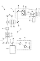
前記光源装置2は、極短パルスレーザ光を出射するパルスレーザ光源4と、該パルスレーザ光源4から発せられる極短パルスレーザ光Lの群速度分散を補償する分散補償光学系5と、分散補償された極短パルスレーザ光Lのオンオフあるいは強度変調する音響光学装置6と、該音響光学装置6とパルスレーザ光源4との間に配置され、音響光学装置6に入射させる極短パルスレーザ光Lを調節する入射補正装置7と、音響光学装置6から出射され、前記蛍光顕微鏡本体3に入射される極短パルスレーザ光Lを調節する顕微鏡入射補正装置8とを備えている。
The
前記分散補償光学系5は、例えば、一対のプリズム9,10とミラー11とから構成されている。あるいはグレーティング対により構成されていてもよい。プリズム9,10どうしの間隔あるいはグレーティングどうしの間隔を調節することで、波長ごとに分散補償量を調節して、パルスレーザ光源4から蛍光顕微鏡本体3の対物レンズ3aに至る全光学系における群速度分散を補償するようになっている。
The dispersion compensation
前記入射補正装置7は、アライメント調節装置12とビーム整形光学系13とを備えている。
前記アライメント調節装置12は、例えば、位置および角度を調節可能な2枚のミラーを備え、極短パルスレーザ光Lの光軸の位置と偏向を調節し、音響光学装置6に対して適正な位置と角度で精度よく入射させるように構成されている。図中、符号14は、パルスレーザ光源4から発せられた極短パルスレーザ光Lを反射して分散補償光学系5に指向させる一方、分散補償光学系5から出力された極短パルスレーザ光Lの光軸から紙面に垂直方向に外れた位置に配置されているミラーである。
The
The
また、ビーム整形光学系13は、分散補償光学系5を通過し、アライメント調節装置12によって位置合わせされた極短パルスレーザ光Lの光束径を絞り、音響光学装置6の結晶15(図2参照)の有効範囲X内に漏れなく入射させるように構成されている。
本実施形態においては、ビーム整形光学系13は、例えば、両凸レンズ16と平凹レンズ17とを組み合わせたガリレイ型のビームエキスパンダにより構成されている。また、ビーム整形光学系13は、パルスレーザ光源4と音響光学装置6との間に、その中央よりも音響光学装置6側に配置されていることが好ましい。また、ビーム整形光学系13は、音響光学装置6の100〜1000mmの位置に配置されていることがさらに好ましい。
Further, the beam shaping
In the present embodiment, the beam shaping
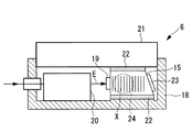
前記音響光学装置6は、図2〜図4に示されるように、例えば、AOMであって、2酸化テルルからなる結晶15と、該結晶15を固定するケース18と、結晶15に接着された圧電素子からなるトランスデューサ19と、該トランスデューサ19に入力する電気信号Eを伝達する音響波発生用電気回路20と、前記結晶15に接着されたヒートシンク(放熱部材)21とを備えている。結晶15とケース18との間、結晶15とヒートシンク21との間には、例えば、シリコーングリースのようなサーマルコンパウンドあるいはインジウム箔からなる界面材22が介在させられている。また、図4中、符号23は、トランスデューサ19から発せられ、結晶15内を伝播した音響波を吸収する吸音材である。
2 to 4, the
結晶15を挟んで対向するケース18の一対の側壁にはそれぞれ開口部24が設けられており、一の開口部24から極短パルスレーザ光Lを入射させ、結晶15を通過した極短パルスレーザ光Lを他の開口部24から出射させるようになっている。
前記ヒートシンク21は、例えば、アルミニウムあるいはアルミニウム合金のような熱伝導率の高い材質からなり、図3に示されるように、平行間隔をあけて配置される複数の平板状のフィン21aを備えている。
An
The
前記顕微鏡入射補正装置8は、アライメント調節装置25と、視準光学系26とを備えている。
アライメント調節装置25は、アライメント調節装置12と同様の構造を有し、蛍光顕微鏡本体3に入射させる極短パルスレーザ光Lの光軸の位置と偏向を精度よく調節することができるようになっている。
The microscope
The
また、視準光学系26は、例えば、図5に示されるように、両凸レンズ27と平凹レンズ28とからなるビーム整形光学系13と同様のガリレイ型のビームエキスパンダと、両凸レンズ27および平凹レンズ28をそれぞれ光軸方向に移動可能に支持する移動機構40,41とにより構成されている。移動機構40,41の作動により、極短パルスレーザ光Lが、蛍光顕微鏡本体3の対物レンズ3aの瞳位置に瞳径と略同等の光束径で入射されるように、出射される極短パルスレーザ光Lの光束径およびビームダイバージェンスを調節することができるようになっている。移動機構40,41は、例えば、手動により、あるいはモータ(図示略)により駆動され両凸レンズ27および平凹レンズ28をそれぞれ所望の位置に配置することができるようになっている。
The collimating
極短パルスレーザ光Lは、光束径W、波面の曲率RおよびビームダイバージェンスDがW=R・Dとなる関係を有している。これら3つの変数W,R,Dはいずれも極短パルスレーザ光Lの波長λ、ビームウエスト位置における光束径W0およびビームウエスト位置からの光軸方向距離の関数である。したがって、これら3つの変数W,R,Dのうち、いずれか2つを決定することにより、極短パルスレーザ光Lを一意に決定することができる。すなわち、光束径WとビームダイバージェンスDとを調節することは、光束径Wと波面の曲率Rとを調節すること、および、波面の曲率RとビームダイバージェンスDとを調節することと等価である。 The ultrashort pulse laser beam L has a relationship in which the beam diameter W, the wavefront curvature R, and the beam divergence D are W = R · D. These three variables W, R, and D are all functions of the wavelength λ of the ultrashort pulse laser beam L, the beam diameter W 0 at the beam waist position, and the optical axis direction distance from the beam waist position. Therefore, by determining any two of these three variables W, R, and D, the ultrashort pulse laser beam L can be uniquely determined. That is, adjusting the beam diameter W and the beam divergence D is equivalent to adjusting the beam diameter W and the wavefront curvature R, and adjusting the wavefront curvature R and the beam divergence D.
前記蛍光顕微鏡本体3は、極短パルスレーザ光Lを2次元的に走査する(例えば、近接ガルバノミラーのような)ガルバノミラー29、走査された極短パルスレーザ光Lを集光して中間像を結像させる瞳投影レンズ30、中間像を結像した極短パルスレーザ光Lを集光して略平行光にする結像レンズ31、略平行光にされた極短パルスレーザ光Lを集光して試料Aに結像させる対物レンズ3a、試料Aにおいて発せられ対物レンズ3aにより集光された多光子蛍光Fを極短パルスレーザ光Lから分岐するダイクロイックミラー32、分岐された多光子蛍光Fを集光する集光レンズ33、集光された多光子蛍光Fを検出する光電子増倍管(PMT)34とを備えている。符号35、36はミラーである。
The fluorescent microscope
このように構成された本実施形態に係る多光子励起型観察装置1の作用について、以下に説明する。
本実施形態に係る多光子励起型観察装置1によれば、パルスレーザ光源4から発せられた極短パルスレーザ光Lが分散補償光学系5を通過させられることによって群速度分散を補償された状態で、入射補正装置7に入射される。
The operation of the thus configured multiphoton excitation observation apparatus 1 according to this embodiment will be described below.
According to the multiphoton excitation observation apparatus 1 according to the present embodiment, the group velocity dispersion is compensated by passing the ultrashort pulse laser light L emitted from the pulse laser light source 4 through the dispersion compensation
入射補正装置7においては、まず、アライメント調整装置12によって、極短パルスレーザ光Lがその光軸の位置および偏向を調整される。次に、ビーム整形光学系13により、光束径を縮小させられた状態で、音響光学装置6に一方の開口部24から入射される。
In the
この場合において、ビーム整形光学系13は、極短パルスレーザ光Lの光束径を縮小して、音響光学装置6の結晶15の有効範囲X内に入射させるように構成されているので、極短パルスレーザ光Lが漏れなく結晶15を通過させられる。
音響光学装置6においては、音響波発生用電気回路20の作動により、所定周波数の電気信号Eがトランスデューサ19に入力され、トランスデューサ19において発生させられた音響波によって、結晶15内における極短パルスレーザ光Lの音響光学効果が発生する。また、トランスデューサ19により発生する音響波の振幅を変更することにより、結晶15内における極短パルスレーザ光Lの回折強度を変化させ、音響光学装置6から出射される極短パルスレーザ光Lの強度を、音響波の振幅に応じた所定の割合で変調する。
In this case, the beam shaping
In the
これにより、入射された極短パルスレーザ光Lが結晶15を通過してケース18の開口部24から、所定の強度に変調された状態で出射されることになる。
この場合において、ビーム整形光学系13によって極短パルスレーザ光Lが結晶15の有効範囲X内に漏れなく入射されているので、結晶15に入射されない極短パルスレーザ光Lや結晶15の側面によって乱反射等される極短パルスレーザ光Lが存在しない。したがって、これらの極短パルスレーザ光Lが迷光となって、正常に結晶15を通過する極短パルスレーザ光Lに混入することがない。
As a result, the incident ultrashort pulse laser beam L passes through the
In this case, since the ultrashort pulse laser beam L is incident on the
その結果、結晶15から出射される極短パルスレーザ光Lにおける波面の乱れの発生が抑制され、PSFの悪化が抑制される。すなわち、対物レンズ3aの前方に形成される試料Aにおけるビームウエスト位置において、光子密度の低下が防止され、多光子励起効果を効率的に発生させることが可能となる。
As a result, the occurrence of wavefront disturbance in the ultrashort pulse laser beam L emitted from the
また、トランスデューサ19により結晶15に入力する音響波をオンオフすることにより、極短パルスレーザ光Lの出射と遮断とを切り替えてオンオフすることができる。例えば、蛍光顕微鏡本体3のガルバノミラー29による極短パルスレーザ光Lの2次元的な走査と同期させて極短パルスレーザ光Lをオンオフすることにより、試料Aに対して所定の走査範囲のみに極短パルスレーザ光Lを照射することが可能となる。
Further, by turning on and off the acoustic wave input to the
また、極短パルスレーザ光Lは音響光学装置6の結晶15内を通過させられる際に音響光学効果によって回折させられる。このとき、結晶15にはトランスデューサ19から音響波が入力されるので、そのエネルギによって結晶15が局所的に発熱する。
The ultrashort pulse laser beam L is diffracted by the acoustooptic effect when it passes through the
本実施形態に係る多光子励起型観察装置1によれば、結晶15自体の熱容量が小さいが、該結晶15に熱容量の大きなヒートシンク21が接着されているので、結晶15において発生した熱はヒートシンク21によって吸収される。また、ヒートシンク21には複数のフィン21aが設けられているので、結晶15から吸収した熱は、これらのフィン21aを介して外気に効率的に放散される。これにより、結晶15の局所的な温度上昇が抑制され、結晶15内の屈折率の変動が大幅に抑制されることになる。
According to the multiphoton excitation observation apparatus 1 according to the present embodiment, the heat capacity of the
結晶15の屈折率が変動すると、結晶15内における極短パルスレーザ光Lの回折が変化するため、音響光学装置6からの出射方向が変化する。したがって、何ら対策を施さない場合には、アライメント調節装置12,25によって極短パルスレーザ光Lの光軸の位置と偏向を厳密に調節しておいても、トランスデューサ19から入力される音響波によって、結晶15の温度が経時的に変化し、それによって結晶15からの出射方向がずれて適正な位置に出射されなくなってしまうことになる。
When the refractive index of the
また、結晶15に入力する音響波の振幅は、その強度変調の程度やオンオフの頻度等の使用状態によって相違するため、使用状態ごとに極短パルスレーザ光Lの出射方向が変化する。
特に、AOMの場合には、音響波を発生させるためにトランスデューサ19に入力する駆動電力が高いこと、および、極短パルスレーザ光Lを入射させる有効範囲の面積が小さいことにより、対策を施さない場合には結晶15内は局所的に加熱される。
Further, since the amplitude of the acoustic wave input to the
In particular, in the case of AOM, no measures are taken due to the high drive power input to the
本実施形態によれば、熱容量の大きなヒートシンク21によって結晶15の温度変化が抑制されるので、音響波を発生させるためにトランスデューサ19に入力する駆動電力が高くても、結晶15における局所的な加熱状態が防止され、極短パルスレーザ光Lの出射方向を一定に維持することができる。その結果、結晶15の経時的な温度変化を検出したり、検出された結晶15の温度に基づいてアライメント調節装置25をその都度調節したりする必要がなく、簡易な構成で、観察開始時に設定されたアライメント状態のままで、試料Aの適正な照射範囲に極短パルスレーザ光Lを照射して、蛍光観察を行うことができる。
なお、本実施形態においては、ヒートシンク21の形態として、平板状のフィン21aを備えるものを例示したが、これに代えて、他の任意の形態のヒートシンク21を採用することができる。
According to the present embodiment, since the temperature change of the
In the present embodiment, the
音響光学装置6から出射された変調後の極短パルスレーザ光Lは、顕微鏡入射補正装置8に入射される。顕微鏡入射補正装置8においては、アライメント調節装置25の作動により、その光軸の位置および偏向を調節された状態で、視準光学系26に入射される。
視準光学系26においては、パルスレーザ光源4から発せられ、分散補償光学系5、アライメント調節装置12、ビーム整形光学系13、音響光学装置6およびアライメント調節装置25を通過してきた極短パルスレーザ光Lの光束径およびビームダイバージェンスを再度補正し直すことにより、蛍光顕微鏡本体3の対物レンズ3aの瞳位置に、その瞳径と略同等の光束径を有するように補正する。これにより、パルスレーザ光源4から発せられた極短パルスレーザ光Lを最も無駄なく効率的に試料Aに集光させ、試料A内に形成されるビームウエスト位置における光子密度を向上させて、効率的に多光子励起効果を発生させることができる。
The modulated ultrashort pulse laser beam L emitted from the
In the collimation
本実施形態においては、視準光学系26を構成する両凸レンズ27および平凹レンズ28が、それぞれ移動機構により光軸方向に位置調節可能に支持されているので、例えば、パルスレーザ光源4が交換された場合、パルスレーザ光源4が出射する極短パルスレーザ光Lの波長を変更可能である場合、パルスレーザ光源4が異なる波長の極短パルスレーザ光Lを出射する複数のパルスレーザ光源を備える場合、波長の変更や光学系の変更等に応じて分散補償光学系によって分散補償量を変更する場合等に移動機構を作動させて両凸レンズ27および平凹レンズ28を光軸方向に移動させることができる。
In the present embodiment, the
したがって、波長の変更等が生じても、極短パルスレーザ光Lが、蛍光顕微鏡本体3の対物レンズ3aの瞳位置に、その瞳径と略同等の光束径を有するように調節することができる。これにより、極短パルスレーザ光Lを常に最も無駄なく効率的に試料Aに集光させ、効率的に多光子励起効果を発生させることができる。また、異なる波長の極短パルスレーザ光Lのビームウエスト位置が光軸方向にずれるのを防止でき、波長にかかわらず、試料Aの同一位置にピントを合わせることができる。
Therefore, even if the wavelength is changed, the ultrashort pulse laser beam L can be adjusted so that the pupil position of the
なお、本実施形態に係る多光子励起型観察装置1および多光子励起型観察用光源装置2においては、ガリレイ型のビーム整形光学系13および視準光学系26を採用したが、これに代えて、複数の凸レンズを有するケプラー型のビーム整形光学系13および視準光学系26を採用してもよい。
また、ビーム整形光学系13は、図6に示されるように、一対の凹面鏡37,38を対向配置することにより構成してもよい。このように構成することで反射光学系によって極短パルスレーザ光Lの光束径を縮小させるので、ビーム整形光学系13を通過する際に群速度分散を生じることがなく、パルス幅が広がることを防止できる。
In the multiphoton excitation observation device 1 and the multiphoton excitation observation
Further, as shown in FIG. 6, the beam shaping
また、図7に示すように、ビーム整形光学系13として、絞り39(あるいはスリットまたはピンホール等の空間フィルタ)を採用してもよい。このようにすることで、簡易な構成により極短パルスレーザ光Lの光束径を縮小させることができ、また調節も簡単であるという利点がある。
Further, as shown in FIG. 7, a diaphragm 39 (or a spatial filter such as a slit or a pinhole) may be employed as the beam shaping
さらに、ビーム整形光学系13においても、該ビーム整形光学系13を構成する両凸レンズ16および平凹レンズ17に、それぞれ、上記移動機構40,41を設け、両凸レンズ16および/または平凹レンズ17を光軸方向に移動させることとしてもよい。このように構成することで、パルスレーザ光源4から出射される極短パルスレーザ光Lの波長の変更等によって、ビーム整形光学系13に入射する極短パルスレーザ光Lの光束径とビームダイバージェンスとが変化しても、移動機構40,41を作動させて、両凸レンズ16または平凹レンズ17の少なくとも一方を光軸方向に移動させることで、出射される光束径とビームダイバージェンスとが一定となるように整形することができる。
Further, also in the beam shaping
したがって、波長等が変更されても、ビーム整形光学系13から出射される極短パルスレーザ光Lを、音響光学装置6の結晶15の有効範囲X内に漏れなく入射させて、効率的に多光子励起効果を発生させることができる。
Therefore, even if the wavelength or the like is changed, the ultrashort pulsed laser light L emitted from the beam shaping
また、ビーム整形光学系13が、2以上のレンズにより構成される場合には、移動機構はその少なくとも1つのレンズを光軸方向に移動させるように構成されていればよい。
また、ビーム整形光学系13が、2つの凹面鏡37,38により構成される場合には、移動機構40,41は、2つの凹面鏡37,38の距離を変更するのみならず、2つの凹面鏡37,38の角度をも変更するように構成されている必要がある。このように構成することで、上記と同様の効果を奏する。
When the beam shaping
When the beam shaping
さらに、移動機構40,41の作動により、レンズ16,17,27,28の位置や凹面鏡37,38の位置および角度等を調節する場合、手動により調節することとしてもよいが、極短パルスレーザ光Lの波長に基づいて移動機構40,41の作動状態を調節する制御装置42を備えることにしてもよい。
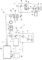
図8に示される例は、波長可変のパルスレーザ光源4を備え、該パルスレーザ光源4から出射される極短パルスレーザ光Lの波長が変更されたときに、分散補償光学系5、アライメント調節装置12,25、ビーム整形光学系13、音響光学装置6、視準光学系26等の各調節装置を制御装置42によりそれぞれ調節する多光子励起型観察装置1である。
Furthermore, when adjusting the positions of the
The example shown in FIG. 8 includes a tunable pulsed laser light source 4, and when the wavelength of the ultrashort pulsed laser light L emitted from the pulsed laser light source 4 is changed, the dispersion compensation
制御装置42には、パルスレーザ光源4から出射される極短パルスレーザ光Lの波長λとその波長λが選択されたときの前記各調節装置の最適な作動状態Y、例えば、分散補償光学系5の分散補償量(プリズムやグレーティングの間隔寸法)、アライメント調節装置12,25を構成するミラーの位置および角度、ビーム整形光学系13および視準光学系26を構成するレンズ16,17,27,28や凹面鏡37,38の位置や角度、音響光学装置6に入力する音響波の周波数等とを対応づけて記憶するメモリ装置43が備えられている。各調節装置の作動状態Yは相互に関連している場合があるので、全ての調節装置に対して、波長λと作動状態Yとが設定されていることが好ましい。
The
そして、パルスレーザ光源4から出射される極短パルスレーザ光Lの波長λが、例えば、パルスレーザ光源Lから出力される波長情報(あるいは、外部から入力される極短パルスレーザ光の波長情報)λによって取得されると、制御装置42は、取得された波長情報λに基づいてメモリ装置43内を検索し、波長λに対応する作動状態Yとなるように各調節装置を自動調節する。これにより、パルスレーザ光源4の波長λの変化にかかわらず、簡易かつ精度よく極短パルスレーザ光Lを漏れなく音響光学装置6の結晶15の有効範囲X内に通過させ、あるいは、対物レンズ3aの瞳位置に瞳径と略同等の極短パルスレーザ光Lを入射させて、試料Aにおける多光子励起効果を効率的に発生させることができる。
The wavelength λ of the ultrashort pulse laser light L emitted from the pulse laser light source 4 is, for example, wavelength information output from the pulse laser light source L (or wavelength information of the ultrashort pulse laser light input from the outside). When acquired by λ, the
なお、採用し得る波長λが予め定められている場合には、上述したように、メモリ装置43に波長λと作動状態Yとを対応づけて記憶しておくことにより、最も簡易かつ精度よく制御できる。しかしながら、この発明は、これに限定されるものではなく、ビーム整形光学系13に入力される極短パルスレーザ光Lあるいはビーム整形光学系13から出力される極短パルスレーザ光Lの光束径を測定し、その測定結果に基づいて、ビーム整形光学系13による光束径の縮小率やビームダイバージェンスが達成できるように制御装置42により移動機構40,41を自動調節することにしてもよい。
When the wavelength λ that can be adopted is determined in advance, as described above, the wavelength λ and the operating state Y are stored in the
また、制御装置42による調節は、波長λの変更により生ずるアライメントのずれ、ビームウエスト位置の移動、ビームダイバージェンスの変動を検出し、それぞれ所望のアライメント、ビームウエスト位置およびビームダイバージェンスが達成できるように各調節装置に対して行われてもよい。
In addition, the adjustment by the
さらに、極短パルスレーザ光Lの採用し得る波長λが有限個に限られる場合には、図9に示されるように、各波長λに適合する距離や角度に予め調節された状態に固定されたレンズ群あるいは凹面鏡からなる複数の補正光学ユニット13A,13B,13Cと、該補正光学ユニット13A,13B,13Cを切り替える切替機構44とを備えるものとしてもよい。この場合においても、波長λと補正光学ユニット13A,13B,13Cとを対応づけてメモリ装置43に記憶しておき、得られた波長情報λに基づいてメモリ装置43内を検索して対応する補正光学ユニット13A,13B,13Cを選択し、切替機構44により切り替えることとすれば、上記と同様に、簡易に高精度の多光子蛍光画像を取得することが可能となる。
Furthermore, when the wavelength λ that can be used by the ultrashort pulse laser beam L is limited to a finite number, as shown in FIG. 9, the wavelength λ is fixed in a state adjusted in advance to a distance and angle suitable for each wavelength λ. A plurality of correction
なお、同様にして、視準光学系26についても、図10に示されるように、複数の補正光学ユニット26A,26B,26Cとこれらを切り替える切替機構45とを有する構造のものを採用することとしてもよい。この場合においても、波長λと補正光学ユニット26A,26B,26Cとを対応づけてメモリ装置43に記憶しておき、得られた波長情報λに基づいてメモリ装置43内を検索して対応する補正光学ユニット26A,26B,26Cを選択し、切替機構45により切り替えることとすれば、上記と同様に、簡易に高精度の多光子蛍光画像を取得することが可能となる。なお、補正光学ユニット13A〜13C、26A〜26Cについては、その数は2以上でよい。
Similarly, as the collimating
また、図5に示される視準光学系26は、レンズ系の移動によってビームダイバージェンスと光束径の両方をコントロールする必要があるので、光学的には複雑になる。そこで、単純な光学系の視準光学系26を構成するために、図11に示されるように、光路調節機構50を設けることにしてもよい。
この光路調節機構50は、例えば、2枚の固定ミラー51,52と2枚の可動ミラー53,54とからなり、可動ミラー53,54を矢印の方向に動かすことで、光路長を調節し、これによって、対物レンズ3aの入射瞳位置、すなわち、ガルバノミラー29の位置における光束径を調節することができるようになっている。
Further, the collimation
The optical
したがって、視準光学系26によって専ら極短パルスレーザ光Lのビームダイバージェンスを調節し、光路調節機構50によって対物レンズ3aの入射瞳位置における光束径を調節することができる。その結果、視準光学系26によって光束径の調節を行う必要がなくなるので、例えば、図示の通りの2枚のレンズ27,28′の組合せのみによって簡易に視準光学系26を構成することができる。なお、光路調節機構50の構成は図11の構成に限定されるものではない。
Therefore, the beam divergence of the ultrashort pulse laser beam L can be adjusted exclusively by the collimating
なお、視準光学系26,ビーム整形光学系13のレンズ構成は、いずれも図示のような両凸レンズと平凹レンズとの組合せに限られるものではなく、正または負のパワーを持つ任意のレンズの組合せで構成されるものであってもよい。
The lens configurations of the collimating
A 試料
F 蛍光
L 極短パルスレーザ光
λ 波長
Y 作動状態
1 多光子励起型観察装置
2 多光子励起型観察用光源装置
3 蛍光顕微鏡本体(観察装置本体)
3a 対物レンズ
4 パルスレーザ光源
8 顕微鏡入射調節装置(入射調節装置)
26 視準光学系(入射調節装置)
26A,26B,26C 補正光学ユニット
27 両凸レンズ(レンズ)
28 平凹レンズ(レンズ)
40,41 移動機構
42 制御装置
43 メモリ装置
45 切替機構
A Sample F Fluorescence L Ultra-short pulse laser light λ Wavelength Y Operating state 1 Multiphoton
3a Objective lens 4 Pulsed
26 Collimation optics (incident adjustment device)
26A, 26B, 26C Correction
28 Plano-concave lens (lens)
40, 41
Claims (11)
該パルスレーザ光源から発せられた極短パルスレーザ光を試料に集光する対物レンズを有し、試料中の前記対物レンズの焦点位置において多光子励起により発せられた蛍光を観察する観察装置本体と、
前記パルスレーザ光源と観察装置本体との間に配置され、パルスレーザ光源から発せられる極短パルスレーザ光の光束径およびビームダイバージェンスを調節する入射調節装置とを備え、
前記パルスレーザ光源が、極短パルスレーザ光の波長を変化させることで、極短パルスレーザ光のビームダイバージェンス及び/又はビームウエスト位置を変化させ、
前記入射調節装置が、前記パルスレーザ光源から出射される極短パルスレーザ光の波長に応じて、試料の同じ深さ位置にビームウエストが配置されるように、前記対物レンズに入射する極短パルスレーザ光のビームダイバージェンスを調整する多光子励起型観察装置。 A pulsed laser light source that emits an ultrashort pulsed laser beam with variable wavelength ;
An observation apparatus main body having an objective lens for condensing an ultrashort pulse laser beam emitted from the pulse laser light source on a sample, and observing fluorescence emitted by multiphoton excitation at a focal position of the objective lens in the sample; ,
An incident adjusting device that is disposed between the pulse laser light source and the observation device main body and adjusts the beam diameter and beam divergence of the ultrashort pulse laser light emitted from the pulse laser light source;
The pulse laser light source changes the wavelength divergence and / or beam waist position of the ultrashort pulse laser light by changing the wavelength of the ultrashort pulse laser light,
The ultrashort pulse that is incident on the objective lens so that the beam waist is arranged at the same depth position of the sample according to the wavelength of the ultrashort pulse laser beam emitted from the pulse laser light source. A multiphoton excitation observation device that adjusts the beam divergence of laser light .
該制御装置が、前記極短パルスレーザ光の波長と、補正光学ユニットとを対応づけて記憶するメモリ装置を備え、極短パルスレーザ光の波長に応じて、前記メモリ装置に記憶されている各波長に対応する補正光学ユニットを選択するように前記切替機構を調節する請求項6に記載の多光子励起型観察装置。 A control device for actuating the switching mechanism according to the wavelength of the ultrashort pulsed laser light emitted from the pulsed laser light source,
The control device includes a memory device that stores the wavelength of the ultrashort pulse laser beam and the correction optical unit in association with each other, and stores each of the memory devices stored in the memory device according to the wavelength of the ultrashort pulse laser beam. The multiphoton excitation observation apparatus according to claim 6, wherein the switching mechanism is adjusted so as to select a correction optical unit corresponding to a wavelength.
該パルスレーザ光源から発せられた極短パルスレーザ光を試料に集光する対物レンズを有し、試料中の前記対物レンズの焦点位置において多光子励起により発せられた蛍光を観察する観察装置本体と、
前記パルスレーザ光源と観察装置本体との間に配置され、パルスレーザ光源から発せられる極短パルスレーザ光の光束径およびビームダイバージェンスを調節する入射調節装置とを備え、
前記入射調節装置が、前記パルスレーザ光源を交換した時に、交換の前後で試料の同じ深さ位置にビームウエストが配置されるように、前記対物レンズに入射する極短パルスレーザ光のビームダイバージェンスを調整する多光子励起型観察装置。 A pulse laser light source that emits ultrashort pulse laser light;
An observation apparatus main body having an objective lens for condensing an ultrashort pulse laser beam emitted from the pulse laser light source on a sample, and observing fluorescence emitted by multiphoton excitation at a focal position of the objective lens in the sample; ,
An incident adjusting device that is disposed between the pulse laser light source and the observation device main body and adjusts the beam diameter and beam divergence of the ultrashort pulse laser light emitted from the pulse laser light source;
When the incident adjustment device replaces the pulse laser light source, the beam divergence of the ultrashort pulse laser light incident on the objective lens is set so that the beam waist is disposed at the same depth position of the sample before and after the replacement. Multiphoton excitation observation device to be adjusted .
Priority Applications (1)
| Application Number | Priority Date | Filing Date | Title |
|---|---|---|---|
| JP2005098423A JP4685489B2 (en) | 2005-03-30 | 2005-03-30 | Multiphoton excitation observation device |
Applications Claiming Priority (1)
| Application Number | Priority Date | Filing Date | Title |
|---|---|---|---|
| JP2005098423A JP4685489B2 (en) | 2005-03-30 | 2005-03-30 | Multiphoton excitation observation device |
Publications (3)
| Publication Number | Publication Date |
|---|---|
| JP2006275915A JP2006275915A (en) | 2006-10-12 |
| JP2006275915A5 JP2006275915A5 (en) | 2008-05-15 |
| JP4685489B2 true JP4685489B2 (en) | 2011-05-18 |
Family
ID=37210828
Family Applications (1)
| Application Number | Title | Priority Date | Filing Date |
|---|---|---|---|
| JP2005098423A Expired - Fee Related JP4685489B2 (en) | 2005-03-30 | 2005-03-30 | Multiphoton excitation observation device |
Country Status (1)
| Country | Link |
|---|---|
| JP (1) | JP4685489B2 (en) |
Families Citing this family (8)
| Publication number | Priority date | Publication date | Assignee | Title |
|---|---|---|---|---|
| US9138913B2 (en) * | 2005-09-08 | 2015-09-22 | Imra America, Inc. | Transparent material processing with an ultrashort pulse laser |
| US8463424B2 (en) | 2007-11-07 | 2013-06-11 | Research In Motion Limited | System and method for displaying address information on a map |
| JPWO2012093437A1 (en) * | 2011-01-06 | 2014-06-09 | コニカミノルタ株式会社 | Surface plasmon resonance fluorescence analyzer and analysis chip used in the analyzer |
| JP5616824B2 (en) | 2011-03-10 | 2014-10-29 | オリンパス株式会社 | Microscope equipment |
| JP6113426B2 (en) * | 2011-09-08 | 2017-04-12 | ギガフォトン株式会社 | Master oscillator system and laser device |
| JP2013070029A (en) * | 2011-09-08 | 2013-04-18 | Gigaphoton Inc | Master oscillator system and laser device |
| JP5942525B2 (en) * | 2012-03-26 | 2016-06-29 | 株式会社Ihi | Temperature distribution observation device |
| NL2018857B1 (en) * | 2017-05-05 | 2018-11-09 | Illumina Inc | Systems and methods for improved focus tracking using a light source configuration |
Citations (6)
| Publication number | Priority date | Publication date | Assignee | Title |
|---|---|---|---|---|
| JPH05134186A (en) * | 1991-11-13 | 1993-05-28 | Olympus Optical Co Ltd | Confocal optical system |
| JPH0651205A (en) * | 1992-06-02 | 1994-02-25 | Olympus Optical Co Ltd | Scanning microscope |
| JPH10206742A (en) * | 1996-11-21 | 1998-08-07 | Olympus Optical Co Ltd | Laser scanning microscope |
| JPH1195091A (en) * | 1997-09-24 | 1999-04-09 | Olympus Optical Co Ltd | Autofocusing microscope |
| JP2002107635A (en) * | 2000-09-29 | 2002-04-10 | Olympus Optical Co Ltd | Laser microscope |
| JP2002139436A (en) * | 1995-09-19 | 2002-05-17 | Cornell Research Foundation Inc | Multiphoton laser microscopic method |
-
2005
- 2005-03-30 JP JP2005098423A patent/JP4685489B2/en not_active Expired - Fee Related
Patent Citations (6)
| Publication number | Priority date | Publication date | Assignee | Title |
|---|---|---|---|---|
| JPH05134186A (en) * | 1991-11-13 | 1993-05-28 | Olympus Optical Co Ltd | Confocal optical system |
| JPH0651205A (en) * | 1992-06-02 | 1994-02-25 | Olympus Optical Co Ltd | Scanning microscope |
| JP2002139436A (en) * | 1995-09-19 | 2002-05-17 | Cornell Research Foundation Inc | Multiphoton laser microscopic method |
| JPH10206742A (en) * | 1996-11-21 | 1998-08-07 | Olympus Optical Co Ltd | Laser scanning microscope |
| JPH1195091A (en) * | 1997-09-24 | 1999-04-09 | Olympus Optical Co Ltd | Autofocusing microscope |
| JP2002107635A (en) * | 2000-09-29 | 2002-04-10 | Olympus Optical Co Ltd | Laser microscope |
Also Published As
| Publication number | Publication date |
|---|---|
| JP2006275915A (en) | 2006-10-12 |
Similar Documents
| Publication | Publication Date | Title |
|---|---|---|
| JP4685489B2 (en) | Multiphoton excitation observation device | |
| JP4759425B2 (en) | Multiphoton excitation observation device | |
| JP4729269B2 (en) | Laser scanning microscope | |
| US10509215B2 (en) | Light-field microscope | |
| JP4922628B2 (en) | Scanning laser microscope | |
| JP5185695B2 (en) | Laser microscope apparatus and specimen image acquisition method | |
| JP5616824B2 (en) | Microscope equipment | |
| JP2007506955A (en) | Scanning microscope with evanescent wave illumination | |
| JP4434882B2 (en) | Laser scanning fluorescence observation system | |
| JP2020021014A (en) | Focal distance variable lens device | |
| JP2007127524A (en) | Multiphoton excitation observation device and multiphoton excitation observing light source device | |
| EP2827180B1 (en) | Scanning optical microscope | |
| JP2006275917A (en) | Multiphoton excitation type observation device and light source device for multiphoton excitation type observation | |
| JP2006301541A (en) | Scanning type fluorescence observation apparatus | |
| JP4642525B2 (en) | Multiphoton excitation observation device | |
| CN107941777B (en) | Anti-bleaching monomolecular positioning three-dimensional super-resolution microscopic system | |
| JP5160372B2 (en) | Laser microscope equipment | |
| JP5590963B2 (en) | Optical apparatus and scanning microscope | |
| JP5059352B2 (en) | Microscope objective lens system, microscope, and microscope observation method | |
| JP2007132794A (en) | Multiphoton excitation type observation device, and light source device for multiphoton excitation type observation | |
| JP4878751B2 (en) | Microscope illumination device and fluorescence microscope device | |
| CN111771150B (en) | Light sheet microscope and sample observation method | |
| JP2010096667A (en) | Laser microscope device | |
| JP5357790B2 (en) | Laser processing equipment | |
| JP6648399B1 (en) | Laser processing apparatus, aberration adjustment method for laser processing apparatus, aberration control method for laser processing apparatus, and laser processing method |
Legal Events
| Date | Code | Title | Description |
|---|---|---|---|
| A521 | Written amendment |
Free format text: JAPANESE INTERMEDIATE CODE: A523 Effective date: 20080327 |
|
| A621 | Written request for application examination |
Free format text: JAPANESE INTERMEDIATE CODE: A621 Effective date: 20080327 |
|
| A977 | Report on retrieval |
Free format text: JAPANESE INTERMEDIATE CODE: A971007 Effective date: 20100520 |
|
| A131 | Notification of reasons for refusal |
Free format text: JAPANESE INTERMEDIATE CODE: A131 Effective date: 20100525 |
|
| A521 | Written amendment |
Free format text: JAPANESE INTERMEDIATE CODE: A523 Effective date: 20100726 |
|
| A131 | Notification of reasons for refusal |
Free format text: JAPANESE INTERMEDIATE CODE: A131 Effective date: 20101116 |
|
| TRDD | Decision of grant or rejection written | ||
| A01 | Written decision to grant a patent or to grant a registration (utility model) |
Free format text: JAPANESE INTERMEDIATE CODE: A01 Effective date: 20110208 |
|
| A01 | Written decision to grant a patent or to grant a registration (utility model) |
Free format text: JAPANESE INTERMEDIATE CODE: A01 |
|
| A61 | First payment of annual fees (during grant procedure) |
Free format text: JAPANESE INTERMEDIATE CODE: A61 Effective date: 20110210 |
|
| FPAY | Renewal fee payment (event date is renewal date of database) |
Free format text: PAYMENT UNTIL: 20140218 Year of fee payment: 3 |
|
| R151 | Written notification of patent or utility model registration |
Ref document number: 4685489 Country of ref document: JP Free format text: JAPANESE INTERMEDIATE CODE: R151 |
|
| FPAY | Renewal fee payment (event date is renewal date of database) |
Free format text: PAYMENT UNTIL: 20140218 Year of fee payment: 3 |
|
| S531 | Written request for registration of change of domicile |
Free format text: JAPANESE INTERMEDIATE CODE: R313531 |
|
| R350 | Written notification of registration of transfer |
Free format text: JAPANESE INTERMEDIATE CODE: R350 |
|
| R250 | Receipt of annual fees |
Free format text: JAPANESE INTERMEDIATE CODE: R250 |
|
| LAPS | Cancellation because of no payment of annual fees |