JP4711505B2 - Tissue-reactive contraceptive device for use in the fallopian tube - Google Patents
Tissue-reactive contraceptive device for use in the fallopian tube Download PDFInfo
- Publication number
- JP4711505B2 JP4711505B2 JP2000512493A JP2000512493A JP4711505B2 JP 4711505 B2 JP4711505 B2 JP 4711505B2 JP 2000512493 A JP2000512493 A JP 2000512493A JP 2000512493 A JP2000512493 A JP 2000512493A JP 4711505 B2 JP4711505 B2 JP 4711505B2
- Authority
- JP
- Japan
- Prior art keywords
- contraceptive device
- fallopian tube
- contraceptive
- coil
- primary coil
- Prior art date
- Legal status (The legal status is an assumption and is not a legal conclusion. Google has not performed a legal analysis and makes no representation as to the accuracy of the status listed.)
- Expired - Fee Related
Links
Images


Classifications
-
- A—HUMAN NECESSITIES
- A61—MEDICAL OR VETERINARY SCIENCE; HYGIENE
- A61F—FILTERS IMPLANTABLE INTO BLOOD VESSELS; PROSTHESES; DEVICES PROVIDING PATENCY TO, OR PREVENTING COLLAPSING OF, TUBULAR STRUCTURES OF THE BODY, e.g. STENTS; ORTHOPAEDIC, NURSING OR CONTRACEPTIVE DEVICES; FOMENTATION; TREATMENT OR PROTECTION OF EYES OR EARS; BANDAGES, DRESSINGS OR ABSORBENT PADS; FIRST-AID KITS
- A61F6/00—Contraceptive devices; Pessaries; Applicators therefor
- A61F6/20—Vas deferens occluders; Fallopian occluders
- A61F6/22—Vas deferens occluders; Fallopian occluders implantable in tubes
-
- A—HUMAN NECESSITIES
- A61—MEDICAL OR VETERINARY SCIENCE; HYGIENE
- A61B—DIAGNOSIS; SURGERY; IDENTIFICATION
- A61B17/00—Surgical instruments, devices or methods, e.g. tourniquets
- A61B17/12—Surgical instruments, devices or methods, e.g. tourniquets for ligaturing or otherwise compressing tubular parts of the body, e.g. blood vessels, umbilical cord
- A61B17/12022—Occluding by internal devices, e.g. balloons or releasable wires
- A61B17/12099—Occluding by internal devices, e.g. balloons or releasable wires characterised by the location of the occluder
-
- A—HUMAN NECESSITIES
- A61—MEDICAL OR VETERINARY SCIENCE; HYGIENE
- A61B—DIAGNOSIS; SURGERY; IDENTIFICATION
- A61B17/00—Surgical instruments, devices or methods, e.g. tourniquets
- A61B17/12—Surgical instruments, devices or methods, e.g. tourniquets for ligaturing or otherwise compressing tubular parts of the body, e.g. blood vessels, umbilical cord
- A61B17/12022—Occluding by internal devices, e.g. balloons or releasable wires
- A61B17/12131—Occluding by internal devices, e.g. balloons or releasable wires characterised by the type of occluding device
- A61B17/1214—Coils or wires
- A61B17/12145—Coils or wires having a pre-set deployed three-dimensional shape
-
- A—HUMAN NECESSITIES
- A61—MEDICAL OR VETERINARY SCIENCE; HYGIENE
- A61B—DIAGNOSIS; SURGERY; IDENTIFICATION
- A61B17/00—Surgical instruments, devices or methods, e.g. tourniquets
- A61B17/12—Surgical instruments, devices or methods, e.g. tourniquets for ligaturing or otherwise compressing tubular parts of the body, e.g. blood vessels, umbilical cord
- A61B17/12022—Occluding by internal devices, e.g. balloons or releasable wires
- A61B17/12131—Occluding by internal devices, e.g. balloons or releasable wires characterised by the type of occluding device
- A61B17/1214—Coils or wires
- A61B17/1215—Coils or wires comprising additional materials, e.g. thrombogenic, having filaments, having fibers, being coated
-
- A—HUMAN NECESSITIES
- A61—MEDICAL OR VETERINARY SCIENCE; HYGIENE
- A61F—FILTERS IMPLANTABLE INTO BLOOD VESSELS; PROSTHESES; DEVICES PROVIDING PATENCY TO, OR PREVENTING COLLAPSING OF, TUBULAR STRUCTURES OF THE BODY, e.g. STENTS; ORTHOPAEDIC, NURSING OR CONTRACEPTIVE DEVICES; FOMENTATION; TREATMENT OR PROTECTION OF EYES OR EARS; BANDAGES, DRESSINGS OR ABSORBENT PADS; FIRST-AID KITS
- A61F6/00—Contraceptive devices; Pessaries; Applicators therefor
- A61F6/06—Contraceptive devices; Pessaries; Applicators therefor for use by females
- A61F6/14—Contraceptive devices; Pessaries; Applicators therefor for use by females intra-uterine type
- A61F6/18—Inserters or removers ; Apparatus for loading an intra-uterine device into an insertion tube
-
- A—HUMAN NECESSITIES
- A61—MEDICAL OR VETERINARY SCIENCE; HYGIENE
- A61F—FILTERS IMPLANTABLE INTO BLOOD VESSELS; PROSTHESES; DEVICES PROVIDING PATENCY TO, OR PREVENTING COLLAPSING OF, TUBULAR STRUCTURES OF THE BODY, e.g. STENTS; ORTHOPAEDIC, NURSING OR CONTRACEPTIVE DEVICES; FOMENTATION; TREATMENT OR PROTECTION OF EYES OR EARS; BANDAGES, DRESSINGS OR ABSORBENT PADS; FIRST-AID KITS
- A61F6/00—Contraceptive devices; Pessaries; Applicators therefor
- A61F6/20—Vas deferens occluders; Fallopian occluders
- A61F6/22—Vas deferens occluders; Fallopian occluders implantable in tubes
- A61F6/225—Vas deferens occluders; Fallopian occluders implantable in tubes transcervical
-
- A—HUMAN NECESSITIES
- A61—MEDICAL OR VETERINARY SCIENCE; HYGIENE
- A61B—DIAGNOSIS; SURGERY; IDENTIFICATION
- A61B18/00—Surgical instruments, devices or methods for transferring non-mechanical forms of energy to or from the body
- A61B18/04—Surgical instruments, devices or methods for transferring non-mechanical forms of energy to or from the body by heating
- A61B18/08—Surgical instruments, devices or methods for transferring non-mechanical forms of energy to or from the body by heating by means of electrically-heated probes
- A61B18/082—Probes or electrodes therefor
-
- A—HUMAN NECESSITIES
- A61—MEDICAL OR VETERINARY SCIENCE; HYGIENE
- A61B—DIAGNOSIS; SURGERY; IDENTIFICATION
- A61B17/00—Surgical instruments, devices or methods, e.g. tourniquets
- A61B2017/00831—Material properties
- A61B2017/00867—Material properties shape memory effect
-
- A—HUMAN NECESSITIES
- A61—MEDICAL OR VETERINARY SCIENCE; HYGIENE
- A61B—DIAGNOSIS; SURGERY; IDENTIFICATION
- A61B17/00—Surgical instruments, devices or methods, e.g. tourniquets
- A61B17/12—Surgical instruments, devices or methods, e.g. tourniquets for ligaturing or otherwise compressing tubular parts of the body, e.g. blood vessels, umbilical cord
- A61B17/12022—Occluding by internal devices, e.g. balloons or releasable wires
- A61B2017/1205—Introduction devices
- A61B2017/12054—Details concerning the detachment of the occluding device from the introduction device
- A61B2017/12059—Joint of soluble material
-
- A—HUMAN NECESSITIES
- A61—MEDICAL OR VETERINARY SCIENCE; HYGIENE
- A61B—DIAGNOSIS; SURGERY; IDENTIFICATION
- A61B17/00—Surgical instruments, devices or methods, e.g. tourniquets
- A61B17/12—Surgical instruments, devices or methods, e.g. tourniquets for ligaturing or otherwise compressing tubular parts of the body, e.g. blood vessels, umbilical cord
- A61B17/12022—Occluding by internal devices, e.g. balloons or releasable wires
- A61B2017/1205—Introduction devices
- A61B2017/12054—Details concerning the detachment of the occluding device from the introduction device
- A61B2017/12063—Details concerning the detachment of the occluding device from the introduction device electrolytically detachable
-
- A—HUMAN NECESSITIES
- A61—MEDICAL OR VETERINARY SCIENCE; HYGIENE
- A61B—DIAGNOSIS; SURGERY; IDENTIFICATION
- A61B17/00—Surgical instruments, devices or methods, e.g. tourniquets
- A61B17/12—Surgical instruments, devices or methods, e.g. tourniquets for ligaturing or otherwise compressing tubular parts of the body, e.g. blood vessels, umbilical cord
- A61B17/12022—Occluding by internal devices, e.g. balloons or releasable wires
- A61B2017/1205—Introduction devices
- A61B2017/12054—Details concerning the detachment of the occluding device from the introduction device
- A61B2017/12068—Details concerning the detachment of the occluding device from the introduction device detachable by heat
- A61B2017/12077—Joint changing shape upon application of heat, e.g. bi-metal or reversible thermal memory
-
- A—HUMAN NECESSITIES
- A61—MEDICAL OR VETERINARY SCIENCE; HYGIENE
- A61B—DIAGNOSIS; SURGERY; IDENTIFICATION
- A61B17/00—Surgical instruments, devices or methods, e.g. tourniquets
- A61B17/12—Surgical instruments, devices or methods, e.g. tourniquets for ligaturing or otherwise compressing tubular parts of the body, e.g. blood vessels, umbilical cord
- A61B17/12022—Occluding by internal devices, e.g. balloons or releasable wires
- A61B2017/1205—Introduction devices
- A61B2017/12054—Details concerning the detachment of the occluding device from the introduction device
- A61B2017/12095—Threaded connection
-
- A—HUMAN NECESSITIES
- A61—MEDICAL OR VETERINARY SCIENCE; HYGIENE
- A61B—DIAGNOSIS; SURGERY; IDENTIFICATION
- A61B18/00—Surgical instruments, devices or methods for transferring non-mechanical forms of energy to or from the body
- A61B18/04—Surgical instruments, devices or methods for transferring non-mechanical forms of energy to or from the body by heating
- A61B2018/044—Surgical instruments, devices or methods for transferring non-mechanical forms of energy to or from the body by heating the surgical action being effected by a circulating hot fluid
- A61B2018/046—Surgical instruments, devices or methods for transferring non-mechanical forms of energy to or from the body by heating the surgical action being effected by a circulating hot fluid in liquid form
-
- A—HUMAN NECESSITIES
- A61—MEDICAL OR VETERINARY SCIENCE; HYGIENE
- A61B—DIAGNOSIS; SURGERY; IDENTIFICATION
- A61B90/00—Instruments, implements or accessories specially adapted for surgery or diagnosis and not covered by any of the groups A61B1/00 - A61B50/00, e.g. for luxation treatment or for protecting wound edges
- A61B90/36—Image-producing devices or illumination devices not otherwise provided for
- A61B90/37—Surgical systems with images on a monitor during operation
- A61B2090/376—Surgical systems with images on a monitor during operation using X-rays, e.g. fluoroscopy
-
- A—HUMAN NECESSITIES
- A61—MEDICAL OR VETERINARY SCIENCE; HYGIENE
- A61B—DIAGNOSIS; SURGERY; IDENTIFICATION
- A61B90/00—Instruments, implements or accessories specially adapted for surgery or diagnosis and not covered by any of the groups A61B1/00 - A61B50/00, e.g. for luxation treatment or for protecting wound edges
- A61B90/36—Image-producing devices or illumination devices not otherwise provided for
- A61B90/37—Surgical systems with images on a monitor during operation
- A61B2090/378—Surgical systems with images on a monitor during operation using ultrasound
-
- A—HUMAN NECESSITIES
- A61—MEDICAL OR VETERINARY SCIENCE; HYGIENE
- A61B—DIAGNOSIS; SURGERY; IDENTIFICATION
- A61B34/00—Computer-aided surgery; Manipulators or robots specially adapted for use in surgery
- A61B34/20—Surgical navigation systems; Devices for tracking or guiding surgical instruments, e.g. for frameless stereotaxis
-
- A—HUMAN NECESSITIES
- A61—MEDICAL OR VETERINARY SCIENCE; HYGIENE
- A61F—FILTERS IMPLANTABLE INTO BLOOD VESSELS; PROSTHESES; DEVICES PROVIDING PATENCY TO, OR PREVENTING COLLAPSING OF, TUBULAR STRUCTURES OF THE BODY, e.g. STENTS; ORTHOPAEDIC, NURSING OR CONTRACEPTIVE DEVICES; FOMENTATION; TREATMENT OR PROTECTION OF EYES OR EARS; BANDAGES, DRESSINGS OR ABSORBENT PADS; FIRST-AID KITS
- A61F2/00—Filters implantable into blood vessels; Prostheses, i.e. artificial substitutes or replacements for parts of the body; Appliances for connecting them with the body; Devices providing patency to, or preventing collapsing of, tubular structures of the body, e.g. stents
- A61F2/0077—Special surfaces of prostheses, e.g. for improving ingrowth
-
- Y—GENERAL TAGGING OF NEW TECHNOLOGICAL DEVELOPMENTS; GENERAL TAGGING OF CROSS-SECTIONAL TECHNOLOGIES SPANNING OVER SEVERAL SECTIONS OF THE IPC; TECHNICAL SUBJECTS COVERED BY FORMER USPC CROSS-REFERENCE ART COLLECTIONS [XRACs] AND DIGESTS
- Y10—TECHNICAL SUBJECTS COVERED BY FORMER USPC
- Y10T—TECHNICAL SUBJECTS COVERED BY FORMER US CLASSIFICATION
- Y10T29/00—Metal working
- Y10T29/49—Method of mechanical manufacture
- Y10T29/49826—Assembling or joining
Abstract
Description
【0001】
(発明の分野)
本発明は、全般的に避妊に関するものであり、一層詳しくは、卵管内避妊具に関する。
【0002】
避妊および永久不妊化のための安全で効果的な方法は世界中で需要がある。様々な避妊および不妊化方法が利用できるが、既存のすべての方法は限界および欠点を有する。したがって、更に安全、低コストで信頼性のある避妊、永久不妊化方法が必要であるということは、先進諸国、開発途上国の両方で、広く認識されている。
【0003】
多くの現在利用できる避妊方法は重要なユーザ参加を必要とする。そして、ユーザ不応諾は失敗の率をきわめて高くしている。バリア方法およびホルモン療法を含めて既存の避妊具の理論的な有効性はかなり確立されているが、全体的な効力を向上させるためにユーザ不応諾を克服することは難しいことが証明されている。
【0004】
ユーザ不応諾の影響が少ない避妊形態の1つとして、子宮内避妊器具(IUD)がある。IUDは、他の市販されている避妊具の大部分よりも信頼性が高く、長期間にわたって有効であることがわかっている。残念なことには、IUDは、また、重大な伝染性併発症も伴う。この理由のために、米国でのIUDの使用は、劇的に減少した。それに加えて、IUDは予期されていない圧出が生じやすく、或るケース・パーセンテージで過度の痛み、出血により取り出さなければならなくなり、これがさらに避妊法としてのIUDの容認率が低下させている。興味深いことには、銅製IUDの効力は、非金属製IUDの効力よりも高いように思えるのである。その理由は充分に説明されてこなかった。
【0005】
永久不妊化のための市販のオプションとしては、卵管血管結紮および精管切除術がある。これらの方法は、外科的であり、元に戻すのが難しく、世界の多くの人々が利用できない。受精が精子および卵子の出会う卵管で起こることは常識である。卵管結紮は卵管の完全な閉塞によって受精を回避している。
【0006】
卵管を可逆的に閉塞することが従来提案されてきた。例えば、エラストマのプラグをインビトロ形成したり、卵管の最も狭い領域(「峡部」と呼ばれる)のいずれかの側に装置を固定したりすることが提案されている。このような卵管閉塞方法は、有望に見えるが、今日までに提案された非外科的装置のうちかなり高いパーセンテージのものがその後の研究で排除されてしまっている。非外科的卵管内装置が残っていたとしても、受胎を防ぐにはほどよく効果的であるということに過ぎないことがわかっている。
【0007】
これらの理由のために、避妊および不妊化のために効果的で、信頼できる卵管内装置を得ることが望まれている。設置のために外科手術を必要としない非常に効果的な卵管内装置を得ることが特に望まれている。このような装置および方法は装置の配置を容易にすることができ、以前に提案された非外科的卵管内装置よりも圧出されにくいということが特に望ましい。
【0008】
(関連技術の説明)
ステンレス鋼製卵管内装置の試験的使用が、RT29の「Investigative Radiology」pp. 570-573(1994)のPenny L. Ross著『Transcatheter Tubal Sterilization in Rabbits』に記載されている。ラットで外科的避妊用卵管内装置として電解質として純粋な銅製のワイヤを試験的に使用したことが、14 Indian Journal of Experimental Biology、pp. 316-319 (May 1976)のD.N. Gupta著『Antifertility Effect of an Intrafallopian Tubal Copper Device』に記載された。
【0009】
英国特許出願公報第2,211,095号が、卵管を閉塞するための子宮ネジ・プラグを記載している。欧州特許出願公報第0,010,812号が、固定用に両端に拡大部を有する輸卵管内設置装置を記載している。同じ装置が、オランダ国特許第7,810,696号に記載されているように思える。
【0010】
卵管閉塞装置の使用が、The Journal of Reproductive Medicine、pp. 65-68 (August 1979)のRobert A. Erb、Ph.D.等の共著、『Hysteroscopic Oviduct Blocking With Formed-in-Place Silicone Rubber Plugs』に記載されている。適所形成式(formed-in-place)エラストマ製卵管閉塞装置がErb.に発行された米国特許第3,805,767号に記載されている。Wolfに発行された米国特許第5,065,751号が、生物学的卵管を可逆的に閉塞する方法および装置を記載している。Cimberに発行された米国特許第4,612,924号が、卵管の口をシールする子宮内避妊器具を記載している。
【0011】
Brundinに発行されたドイツ国特許第2803685が、体液と接触したときにふくらむ装置を備えた、人体の管に栓をする装置を記載している。
代案の避妊具が、共同係属中の米国特許出願第08/474779号に記載されている。この米国特許の全開示内容は参考資料としてここに援用する。
【0012】
(発明の概要)
本発明は、受胎を防ぐために設置する卵管内装置および方法を提供する。本発明の卵管内装置は、外科的処置を必要とせず、あるいは、子宮内避妊器具(IUD)と関連した出血、痛み、感染を増大させる危険なしに、卵管内に頚部を横切って送り出され、その中に機械的に固定されて長期避妊あるいは永久不妊化を行う。
【0013】
本発明の卵管内装置は、しばしば、螺旋形の外面を有する管腔横断領域を有する構造からなる。螺旋形の表面は、拡大した二次形状を形成、好ましくは、遠位、近位の固定ループを形成するように付勢される構造の弾力的な部分によって機械的に固定される。固定ループは、螺旋形の外面が所定位置から回転するのを防ぎ、卵管内で軸線方向の運動を防ぐのに役立つ。別の実施例において、曲がりくねった卵管の軸線方向曲率によって弾力的に偏倚されるまっすぐなコイルによって固定を行い、半径方向に拡大可能な組紐、malecottまたは他の管状構造が装置を卵管内に取り付けるのに役立つことができる。
【0014】
本発明の卵管内装置で銅を使用した場合、避妊方法としての効力が向上する。しかしながら、可塑的に変形可能な材料から形成した装置は卵管内にたやすく拘束することができない。明らかに、卵管の実際の形状、寸法がかなり変化するので、予形成した変形可能な卵管内装置のための信頼性ある固定を行えない。したがって、本発明の卵管内装置は、しばしば、弾力性構造、通常は金属製のコイルを包含する。金属としては、銅合金またはメッキがあり、理想的には、少なくとも75%の銅を含む合金がある。コイル材料としては、代表的には、ベリリウム、亜鉛、ステンレス鋼、プラチナ、形状記憶合金(例えば、Nitinol(登録商標))などがある。好ましくは、コイルはベリリウムと銅の合金からなるものである。
【0015】
本発明の装置は、ほぼ閉塞を行うことになるが、精子と卵子が出会うことを防ぐように卵管を完全に閉塞する必要はない。その代わりに、いくつかの実施例において、弾力的な構造上に銅が存在すれば、避妊を効果的に行うの充分である。それ故、開いた管腔の存在にも係わらず、卵管の通常の構造または機能あるいはこれら両方を崩すことによって避妊を行うことができる。この概念は、本願明細書においては「機能的閉塞」と称する。ここで使用している機能的閉塞とは、卵管に移植したときに、装置が卵管の通常の構造または機能あるいはこれら両方を崩して受精または受胎あるいはこれら両方を抑制することを意味する。
【0016】
都合の良いことに、本発明は、頚部横断式導入よるこのような卵管内装置の非外科的設置を更に包含する。弾力的な構造は、例えば、コアワイヤを用いてまっすぐな形態に拘束可能であり、これが導入をかなり容易にし、それに伴う危険をかなり減らす。したがって、既存の外科的避妊、不妊化作業に伴うコストおよび危険は避けられる。弾力的な構造は、しばしば、コイルからなる。いくつかの実施例において、或る要素がコイルに沿って配置され、受胎を禁ずる卵管組織の組織反応を生じさせるようになっている。コイルの遠位アンカーを峡部の遠位にあるアンプラに挿入することができ、一方、近位アンカーは卵管口に位置する。これらのアンカーは、装置の回転を防ぎ、また、軸線方向移動を避けるのに役立つ。あるいは、長さ、形態に依存して、これらのアンカーのうち少なくとも一方を卵管口を過ぎた卵管内の任意の位置に設置し、他方を子宮内に延ばすようにしてもよい。好ましくは、少なくとも或る種の固定を、卵管の峡部領域まで卵管壁に沿って行う。いくつかの実施例において、周囲の管腔壁に対する管腔内装置の電気外科的取り付けで、ループおよび他の固定構造なしでも、効果的な固定を行える。代表的にはハンダ・ボンドを電気分解で溶解させることによって卵管内装置を送り出しシステムから切り離すのに電流も使用できる。電流はアンカーを起動することもできる。例えば、卵管内で弾力的な半径方向に拡大可能な管状構造を解放することができる。
【0017】
本発明は、また、受胎を防ぐために卵管内に組織反応を生じさせる改良型の避妊具を提供する。この卵管内装置グループは、しばしば、非常に可撓性のあるコイル構造を使用し、繊細な卵管組織に損傷を与えたり、それを突き抜けたりすることを防ぐことになる。所望の組織反応は、卵管内装置の材料の結果であってもよいし、コーティング、表面処理、装置と周囲卵管壁との機械的な相互作用により生じるものであってもよい。組織は、しばしば、卵管閉塞、卵管組織の輸送機構の遮断、卵管内装置の卵管内拘束などによって受胎を妨げる。これらの意図した結果を与えることのできる特殊な組織反応としては、避妊具または卵管あるいはこれら両方への組織内殖、瘢痕組織形成、卵管組織の硬化などがある。
【0018】
1つの特徴によれば、本発明は、卵管で使用するための組織反応型避妊具を提供する。この避妊具は、近位端、遠位端を有し、これらの端間に軸線を構成するコイルからなる。このコイルは、軸線方向に可撓性であり、卵管に挿入するのに適した横断面を有する。コイルに沿って配置されている要素は、コイルに隣接した卵管組織に組織反応を生じさせ、受胎を阻害する。
【0019】
いくつかの実施例において、内殖促進要素は避妊具内への卵管組織の内殖を促進することができる。例えば、内殖促進要素として、編んだあるいは織ったポリエステル、微孔性材料または表面処理などがある。あるいは、鋭い縁の付いた螺旋形のリボンまたは他の機械的相互作用要素が瘢痕組織の形成を生じさせることができるし、または、コイルの表面コーティングが卵管組織を硬化させ、受胎輸送のじゃまをする頑丈な線維性結合組織の形成を促すことができる。多くの実施例において、組織反応と組み合わせわった避妊具の存在は、卵管の完全閉塞に依存することなく効果的な避妊を行うことができる。
【0020】
別の特徴によれば、本発明は卵管で使用するための組織内殖避妊具を提供する。この避妊具は、近位端、遠位端およびこれらの端間の軸線を有する管状の保持構造からなる。この保持構造は、軸線方向に可撓性であって、卵管内に挿入可能である。卵管組織の内殖を生じさせ得る材料がこの保持構造に取り付けられ、この保持構造から半径方向に露出する。
【0021】
典型的な実施例において、保持構造は、内殖材料を配置した螺旋形のコイルを包含する。このような螺旋形のコイルは、オプションとして、卵管内で半径方向に拡大することができ、それによって、避妊具を多種多様な卵管生理学状態に適応させることができる。内殖材料としては、ポリエステル、PTFEなどの編んだか織った繊維の形をしていてもよい。
【0022】
別の態様においては、本発明は、卵管で使用するための組織内殖型避妊具を提供する。この避妊具は、近位端および遠位端を有し、これらの端間に軸線を構成している細長い弾力的なボデーからなる。保持構造が、前記弾力的なボデーに沿って配置されている。この保持構造は、卵管内に弾力的なボデーを拘束するようになっている。ボンドが保持構造を弾力的なボデーに取り付けている。弾力的なボデー、保持構造、および、ボンドのうちの少なくとも1つは組織内殖を促進する微孔性材料からなる。
【0023】
本発明に関連するものとして、卵管内に避妊具を頚部横断式に挿入することからなる避妊方法を開示する。避妊具は、避妊具の遠位側ボデーを卵管壁に対して弾力的に偏倚させ、卵管に沿って、前記遠位側ボデーが避妊具を案内するようになっている。組織反応が、卵管組織内の避妊具の要素によって生じる。この組織反応が卵管内に避妊具を取り付ける。
【0024】
本発明は、また、卵管の広範囲にわたって変化する形状、寸法に使用するようになっている改良型の避妊具、システムおよび方法を提供する。卵管の生理学的な広範囲にわたる変化を認識することによって、本発明の避妊構造は、卵管内で半径方向に拡大して卵管壁に係合することができる。驚くべきことに、本発明の避妊具は、しばしば、弾力的な螺旋形コイルのような管状構造を使用する。このような管状の器具は、しばしば、卵管を完全に閉鎖するのではなく、卵管組織の構造または輸送機構あるいはこれら両方を壊すことによって避妊を行うことになる。本発明の管状の避妊具を貫く通路は、オプションとして、例えば、螺旋形のコイル内に編んだあるいは織ったポリエステル繊維を含ませることによって、器具内で組織内殖を促進させることによって閉塞することができる。とにかく、このような管状の保持構造は、さかとげ等を突き出すことに頼ることなく、安全に避妊具を固定するように広範囲にわたる卵管サイズを通じて卵管壁に向かって半径方向に拡大することができる。
【0025】
或る特徴によれば、本発明は、卵管壁を有する卵管で使用するための避妊具を提供する。この避妊具は、近位端、遠位端およびこれらの端間の軸線を有する管状の保持構造を包含する。この保持構造は、細い形態からその場で半径方向に拡大し、第2の拡大した直径を構成する(この場合、保持構造は、卵管内に軸線方向に挿入するのに適した第1の直径を有する)。拡大した保持構造は、周囲の卵管壁に係合し、卵管内に避妊具を保持するようになっている。
【0026】
別の特徴によれば、本発明は、卵管壁を有する卵管で使用するための避妊具を提供する。この避妊具は、軸線を構成する受胎阻害体を包含する。螺旋形のコイルが、この受胎阻害体のまわりに配置されている。この螺旋形のコイルの一部は受胎阻害体に対して動くことができ、螺旋形のコイルが或る卵管横断面サイズ範囲にわたって弾力的に拡大することができるようになっている。それ故、コイルは周囲の卵管壁と半径方向に係合し、卵管内に避妊具を安全に取り付けることができる。
【0027】
本発明は、また、ほぼまっすぐである細長いコイルを有する卵管内避妊具を提供する。驚くべきことに、このようなまっすぐなコイルが曲がりくねった卵管内で軸線方向に配置されたとき、卵管によって強制されたコイルの弯曲部がコイルの弾力的な固定を生じ得るのである。このようなまっすぐなコイルは、また、卵管内へ(そしてその内部で)避妊具を前進させるときに非常に有利である。まっすぐな弾力的なコイルは、卵管内での器具の頚部横断式展開中に一体のガイド・ワイヤとして作用し得る。それによって、ガイド・ワイヤ、卵管軸線カテーテルなどを引き続いて使用しなければならないときに発生する遅延を避けることができる。
【0028】
本発明は、卵管で使用するための卵管内避妊具を提供する。この避妊具は、近位端、遠位端およびこれらの端間にある軸線を有する細長いコイルを包含する。コイルの静止時、軸線はほぼまっすぐである。そして、コイルは軸線方向に弾力的であり、卵管へ軸線方向に受胎阻害体を挿入するのを容易にする。避妊具は、受胎を阻害するように卵管内に保持されるようになっている。
【0029】
別の特徴によれば、本発明は、卵管で使用するための卵管内避妊具を提供する。卵管の壁は、卵管横断面および軸線方向湾曲部を有する。この避妊具は、近位端および遠位端を有し、これらの端間で軸線を構成している細長いボデーを包含する。この細長いボデーは、卵管横断面内に軸線方向に挿入するのに適した横断面を有する。この細長いボデーの少なくとも一部は、卵管の軸線方向湾曲よりまっすぐである。細長いボデーは、卵管壁を傷つけることなく卵管壁に対して偏倚するに充分に可撓性である。この細長いボデーは、また、まっすぐな部分が卵管の軸線方向湾曲に沿って撓んだときに、卵管の壁に対して固定力を加えるに充分に弾力的である。
【0030】
別の特徴によれば、本発明は、軸線を有する卵管で使用するための避妊具を提供する。この避妊具は、近位端、遠位端およびこれらの端間にある軸線を有する構造を包含する。卵管内にほぼ同軸に配置されたとき、この構造は、効果的な卵管閉塞を行うようになっている。細長い部材がこの閉塞構造に取り付けられており、この細長い部材は、充分に可撓性であり、軸線方向に弾力的であり、卵管内で閉塞構造を遠位方向へ前進させるときにそれを案内するのに役立つ。
【0031】
本発明によって関連する避妊方法において、細長い弾力性のあるボデーが軸線方向に湾曲している卵管内へ頚部横断状態で挿入される。湾曲したボデーは、卵管内でこの湾曲したボデーを固定するのに役立つ固定力を与える。この取り付けられた弾力性のあるボデーは、受胎を阻害するように卵管内に固定される。
【0032】
本発明に関連するものとして、さらに、避妊具の遠位ガイド・ワイヤ状構造で避妊具を案内することによって卵管に沿って卵管内避妊具を頚部横断式に挿入する段階を包含する避妊方法を開示する。少なくともガイド・ワイヤ状構造の一部を含めて避妊具は受胎を阻害するように卵管内に保持される。
【0033】
別の特徴によれば、本発明は、避妊用キットを提供する。この避妊用キットは、卵管内避妊具および使用説明書を包含する。前記使用説明書は、避妊具を頚部横断式に卵管内に導入し、卵管内に避妊具を取り付ける段階を記載している。オプションとして、ガイド・ワイヤ、コアワイヤ、送り出しカテーテルなどを含む様々な送り出し構造もキット内に設けることができる。
【0034】
また別の特徴によれば、本発明は、近位端および遠位端を有する細長い送り出しボデーを包含する卵管内避妊システムを提供する。第1のエネルギ導管が近位端、遠位端間に延びており、遠位端付近にある卵管内構造が第1の横断面を有する。エネルギ源が、第1の導管によってこの卵管内構造に接続している。このエネルギ源からのエネルギはこの卵管内構造を第2の横断面に拘束し、卵管内に構造を拘束し、受胎を阻害する。
【0035】
最後の特徴によれば、本発明は、近位端、遠位端を有し、前記近位端と前記遠位端との間に延在する第1の導体、第2の導体を有する細長い送り出しボデーを提供する。卵管内避妊構造が前記送り出しボデーの遠位端付近にある。第1の導体、第2の導体によって電力供給源を前記卵管内避妊構造に接続できる。この有利な二極配置は、例えば、前記卵管内避妊構造の少なくとも一部を通じて手持ち式電池から電流を伝送することによって形状記憶合金構造の起動を行うことができる。
【0036】
(実施例の詳細な説明)
本発明は、永久避妊手段、可逆的避妊手段の両方として交互に使うことができる避妊用卵管内器具を包含する。本発明に関連する避妊方法および本発明の避妊具は、従来の避妊技術の効力を制限していた不使用による危険を最小限にする。さらに、本発明の器具の卵管内への設置は、子宮内避妊器具(IUD)に伴う伝染性併発症、出血量増大および骨盤痛の危険を減らす。本発明の卵管内器具の設置および新規な形状は、IUD以上の有意の利点を提供する。IUDは、過度の疼痛、出血により予定外の圧出、取り出しをしなければならないことが多いことがわかっている。本発明は、銅製のIUDに伴う効果の増大という利点を利用し、手術を必要とすることなく頚部を横切って配置することができる銅を含む弾力的な構造を提供する。
【0037】
本発明に関連する避妊方法は卵管閉塞方法と一般に呼ばれる一群の避妊技術内に含まれるが、この避妊方法は、必ずしも受精を防ぐために卵管を閉塞することだけに依存するというわけではない。その代わりに、避妊が卵子輸送、受精プロセス、卵子の卵割などを壊すことによって行われることは明らかである。これらのプロセスに銅が与える効果は充分にわかってはいないが、銅製の卵管内器具は他の材料で形成した卵管内器具以上に効果の向上を潜在的に行うと思われる。あるいは、避妊は、器具に取り付けた殺精子剤によって行われる、あるいは強化され得る。オプションとして、本発明は、さらに、卵管内での組織の成長を促進して卵管の閉塞を誘発し、さらに受胎を阻害する器具を包含する。いくつかの実施例においては、ポリエステル繊維、例えば、Dacron(登録商標)、Rayon(登録商標)などを、重合体接着剤を使用してコイルの表面に接合する。ポリエステル繊維はコイルまわりの組織成長を促進し、さらに、卵管から装置が圧出される可能性を減らす。
【0038】
都合の良いことに、本発明の弾力的な構造は、コアワイヤを介して解放自在に取り付けるようになっており、このコアワイヤが弾力的な構造をまっすぐな形態に拘束する。まっすぐな形態のときには、この弾力的な構造は卵管の内径より小さい外径を有するので、本発明の卵管内器具を含んでいるカテーテルを容易に頚部横断状態で導入することができる。
【0039】
本発明は、卵管の峡部内に固定することができる。このことが、意図しない避妊具の圧出、その結果の避妊方法の失敗を克服する。このような卵管内器具圧出は、設置しやすい卵管内避妊技術の効力を制限しているただ1つの最大のファクタであった。本発明の卵管内器具は、二次形状に予形成したほぼ細長い弾力的な構造である。これらの二次形状は、好ましくは、卵管の最も細い部分(峡部と呼ばれる)の近位方向、遠位方向でのアンカーを形成することになる。二次形状は、好ましくは、峡部の内径よりも大きい外径を有する。固定は、卵管管腔の他の部分をまたぐ、しばしば、卵管口と峡部の間の構造でも可能である。
【0040】
本発明の器具は、一般的に、近位端付近で弾力的な構造を釣り上げ、弾力的な構造の近位方向に引っ張り、弾力的な構造をまっすぐにし、引き出せるようにすることによって卵管に損傷を与えることなく容易に取り出すことができる。あるいは、器具を卵管内に設置した後に器具に電流を付加し、永久不妊化を行う。電流は、また、米国特許第5,624,449号に記載されているものと同様のシステムを用いて送り出しシステムから器具の分離するのに効果があるかも知れない。なお、この米国特許の全開示内容は、本願明細書において参考資料として援用する。アンカーのその場での起動は、同様の機構で弾力的な構造を解放してその場で拡大させるか、あるいは、形状記憶合金の電流誘発位相変化によって(例えば、電流によってまっすぐなNitinol(登録商標)リボンを卵管内でカールさせることによって)行うことができる。
【0041】
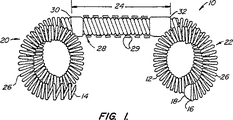
以下、図1を参照して、本発明の避妊用卵管内器具10の第1実施例は、弾力的な一次コイル12から形成される。一次コイル12は、近位端14および遠位端16を有する。遠位端は、非外傷性エンドキャップ18を有する。一次コイル12は、さらに、3つの部分を包含する。すなわち、近位アンカー20、遠位アンカー22、および、管腔横断領域24である。以下に説明するように、近位アンカー20、遠位アンカー22は固定ループ26を形成するように付勢されている。
【0042】
管腔横断領域24は、一次コイル12のほぼまっすぐな部分からなる。リボン28が、一次コイル12の外面に巻き付けてあり、螺旋形状を与えている。リボン28は、鋭い外縁29を包含する。この外縁は、卵管内器具10にトルクを加えたときに卵管壁に管腔横断領域24をしっかりと固定する。リボンは、好ましくは、高強度生物学的適合性金属、理想的にはステンレス鋼で作る。リボンは、近位ジョイント30および遠位ジョイント32(ハンダ、熱収縮性管材料等で形成することができる)のところで一次コイル12に取り付けられる。
【0043】
以下、図2を参照して、一次コイル12は円筒形のコイル、または、ばねとしてまっすぐな形態に形成するのが最も容易であり、好ましくは、約0.127mmから約1.27mm(0.005インチから0.05インチ)の範囲の外径を有し、そして、20mmから150mmの範囲の長さを有する。理想的には、一次コイル12は、約0.254mmから約1.27mm(0.01インチから0.05インチ)の範囲の外径を有し、30mmから125mmまでの範囲の長さを有する。
【0044】
好ましくは、一次コイル12は、ベリリウム銅合金ワイヤから形成される。ベリリウム銅は、器具の圧出を回避するのに必要な弾力性を与え、また、銅製避妊用卵管内器具の効果を向上させる。このようなベリリウム銅ワイヤは、代表的には、約0.0508mmから約0.254mm(0.002インチから0.01インチ)の直径を有する。銅製卵管内器具の効力を向上させるために、一次コイル12は、好ましくは、75%の銅を含有する合金からなる。あるいは、一次コイル12は、弾力的な金属、例えば、ステンレス鋼、プラチナ、形状記憶合金等から形成される。このような材料を使用する場合、一次コイル12は、銅または銅合金でメッキしてもよいし、あるいは、銅を取り付けてもよい。
【0045】
一次コイル12は、ボデー巻回部42とネジ巻回部44を包含する。ボデー巻回部42は、可能な限り最小のピッチで形成し、一次コイル12の剛性を高めている。ネジ巻回部44は、代表的には、近位端14に隣接して0.1cm〜2.0cmまでのところにあり、ボデー巻回部42のピッチのほぼ二倍のピッチを持つことになる。
【0046】
以下、図3を参照して、近位、遠位アンカーは、一次コイル12の選択部分に曲がった二次形状を与えることによって形成する。この二次形状は、好ましくは、一次コイル12を曲げ、その後に一次コイルを熱処理することによって形成したループ26を包含する。多種多様な二次形状を使用できる。例えば、正弦波カーブ、交互ループまたは「フラワー・コイル」を形成するようにまっすぐな部分で分離した複数のループがあり、これらは出願中の米国特許出願第08/474779号により充分に記載されており、この米国特許の全開示内容を参考資料として本願明細書で援用する。たいていの場合、湾曲した二次形状は、効果的な固定を行うように卵管より大きい外側横断面46を有する。
【0047】
以下、図4を参照して、卵管内器具10(図1)と共に使用するためのコアワイヤ50は、遠位端54に向かってテーパの付いた弾力的なワイヤ52からなる。ワイヤ52は、まっすぐな形態に卵管内器具10を拘束するに充分に剛性であり、代表的には、ステンレス鋼、プラチナ等からなる。コイルの短い部分はネジ・ジョイント58で取り付けたコアワイヤ・ネジ山56を形成する。ネジ山56は、一次コイル12のネジ巻回部44の巻回数、ピッチに対応している。
【0048】
以下、図5を参照して、卵管内避妊システム60は、卵管内器具10を通して管腔62内に挿入されるコアワイヤ50からなる。卵管内器具10は、ネジ巻回部44をネジ山56と係合させることによって解放自在に取り付けられる。したがって、ひとたび卵管内器具10を所定位置に設置したならば、卵管内器具10はコアワイヤ50の近位端にトルクを与えることによって解放される。
【0049】
以下、図6を参照して、本発明の卵管内器具の別の実施例は、ここでも再び、近位端114および遠位端116を有する弾力的な一次コイル112から形成される。近位端114は、摩擦フィッティング115を包含する。一次コイル112は、ここでも再び、3つの部分を包含する。すなわち、近位アンカー120、遠位アンカー122および管腔横断領域124である。近位アンカー120、遠位アンカー122は、対向した固定ループ26を形成するように付勢されており、それによって、近位アンカー120、遠位アンカー122のゆるんだときの全体的な横断面を大きくする。リボン128が、上記したように、螺旋形の形を与えるように一次コイル112の外面に巻き付けてある。
【0050】
以下、図7を参照して、一次コイル112は均一なボデー巻回部142を包含する。二次形状は、対向したループ126としてか、あるいはフラワー・コイルの複数のループとしてまっすぐな円筒形コイルに与えられる。
【0051】
以下、図8を参照して、別の卵管内器具100を使用している卵管内避妊システムは、遠位端154に向かってテーパの付いているコアワイヤ152を包含する。摩擦フィッティング115がコアワイヤ152に嵌合し、一次コイル112をまっすぐな形態に拘束する。リリース・カテーテル164が、別の卵管内器具100の近位側でコアワイヤ152上に摺動可能に配置してあり、リリース・カテーテルに対してコアワイヤ152を引くことによって器具を解放することができる。
【0052】
本発明の避妊用卵管内器具の使用を、図9、図10を参照ながら説明する。誘導針カニューレ70を、子宮72を通して卵管口74の領域に頚部横断式に挿入する。あるいは、子宮鏡を誘導針カニューレ70の代わりに使用してもよいし、または、エコー源及び/又は放射線不透過性の器具をソノグラフィックまたは放射線不透過性の案内の下に配置してもよい。
【0053】
卵管内避妊システム60は、誘導針カニューレ70の遠位方向に進められ、卵管を通して操作する。最終的には、好ましくは、卵管内器具10は峡部の遠位側まで延びる。オプションとして、卵管内避妊システム60は、自己案内式であり、管腔内操作を支援するようにコアワイヤ52を遠位端54付近で曲げる。あるいは、ガイド・ワイヤおよびカテーテルを最初に卵管内に進め、ガイド・ワイヤの代わりに卵管内避妊システム60を使用する。いずれにせよ、卵管内器具は、一般的に、峡部80に隣接した目標領域84内に管腔横断領域24を置いて軸線方向に位置決めすることになる。好ましくは、遠位アンカー22の少なくとも1つのループが目標領域84の近位側にあり、遠位アンカー弯曲部、近位アンカー弯曲部を形成する。
【0054】
ひとたび卵管内器具10を正しく位置決めしたならば、コアワイヤ50にトルクを与え、リボン28を卵管壁内にセットする。次に、コアワイヤを反対方向に回転させ、ネジ山56をネジ巻回部44から外すことによって、コアワイヤを卵管内器具10から外す。次に、コアワイヤを自由に近位方向へ摺動させ、一次コイルを解放することができる。一次コイルの遠位端を解放したとき、遠位アンカー弯曲部90が形成される。同様に、近位ループは近位アンカー弯曲部92を形成する。アンカー弯曲部は、卵管内で器具を軸線方向に拘束し、また、管腔横断領域24の螺旋形状まわりの回転を阻止するのに役立つ。図10から分かるように、ループは効果的な遠位アンカーあるいは近位アンカーを与えるのにゆるんだ形態を採る必要はない。
【0055】
本発明は、さらに、コアワイヤを引き抜く前に卵管内器具にコアワイヤを通して電流を通すことによって、永久不妊化を行う。卵管内器具と接触する卵管組織は、乾燥させられ、本発明の卵管内器具に取り付けられる。この操作によって、また、卵管の永久損傷を生じさせ、これが卵管内器具を包む瘢痕組織を形成し、卵管の管腔の永久閉塞を生じさせる。明らかに、コアワイヤ/一次コイル・インタフェースは導電性であって、本発明による非外科的永久不妊化方法ができるようにしなければならない。
【0056】
本発明に関連する卵管内避妊方法および本発明の避妊具は、避妊具が卵管の管腔を完全に閉塞しない場合でも、非常に効果的な避妊を行える。繊細な卵管組織の膨満を最小限に抑えるために、本発明は、しばしば、少なくとも初めて展開したときに、卵管内に若干開いた管腔を残すこといなる。実際、これらの避妊具は、しばしば、管腔を有する孔明き管状構造を包含する。それでもなお、開いた管腔の存在にもかかわらず、卵管の通常の構成または機能あるいはこれら両方を壊すことによって避妊を行うことができる。この概念は、ここでは「機能的閉塞」と呼ぶ。ここで使用している機能的閉塞を行う器具とは、卵管内に移植したときに、卵管の通常の構成または機能あるいはこれら両方を壊して受精または受胎あるいはこれら両方を阻害する装置を意味する。
【0057】
機能的閉塞を行うのに必要な閉鎖器具のサイズは、器具の材質、器具を卵管ないで展開しようとしている位置、器具と周囲の卵管壁との相互作用などに依存し得る。例えば、ポリエステルの繊維を包含する卵管内避妊構造は、器具内への卵管組織の内殖を生じさせ得る。この組織/器具相互作用の結果として、内殖を促進する比較的小さい器具が効果的な閉塞を行うことができる。実際、このような器具は充分な内殖を生じさせることによって完全な閉塞を行うことができ、その結果、この器具と組み合わせた増殖性炎卵管壁が卵管の管腔を通るすべての通路を閉塞する。それ故、比較的小さくて、挿入しやすい構造で、卵管壁を膨満させることなく効果的に受胎を阻止できる。
【0058】
効果的な卵管閉塞を行うことができる1つの挿入しやすい卵管内避妊構造が図11Aに示してある。まっすぐな避妊具200は、上述したように螺旋形の二次コイル204をまわりに配置したまっすぐな一次コイル202を包含する、二次コイル204は、一対のボンド206のところで一次コイル202に取り付けられる。図6に示すように、螺旋形の二次コイルは、一次コイル202の外面より大きく、周囲の卵管壁に二次コイルの角隅を埋め込むのを容易にし得る内面を有し得る。しかしながら、先に説明した卵管内器具とは異なり、一次コイルが静止しているとき、まっすぐな避妊具200は近位端208と遠位端210の間でほぼまっすぐに留まる。
【0059】
一次コイル202は、代表的には、約0.254mmから約1.016mm(約0.010〜0.040インチ)の直径を有するコイルを形成するようにワイヤを巻き付けることによって、約0.0508mmから約0.2286mm(約0.002〜0.009インチ)の直径を有するワイヤから形成されることになる。一次コイル202は、しばしば、2.9cmから3.5cmの長さを有する。螺旋形の二次コイル204を形成するのに用いるリボンは、一般的に、約0.127mmから約0.508mm(約0.005〜0.020インチ)の幅を有し、約0.0127mmから約0.508mm(約0.0005〜0.005インチ)の厚みを有する。
【0060】
典型的な実施例において、まっすぐな避妊具200は、約3.0cmから3.35cmの全長を有する一次コイル202を包含する。典型的な一次コイル202は、プラチナ・ワイヤを巻いて形成され、プラチナ・ワイヤは、約0.127mm(0.005インチ)の厚さを有し、約0.4572mm(約0.018インチ)の外径を有し、約3.0cmの長さを有する一次コイルを得るように巻回する。二次コイル204は、約0.3048mm(0.012インチ)の幅を有し、約0.0508mm(0.002インチ)の厚みを有するプラチナ・リボンから形成される。ボンド206はゴールド・ハンダからなり、二次コイル204は、一次コイル202に取り付けられたときに、約0.5cmから1.0cmの長さを有し、約0.889mmから約1.016mm(約0.035〜0.040インチ)の外径を有する。ハンダは、また、遠位端210のところで非外傷性チップを形成するのにも用いられる。
【0061】
以下、図11B、図11Cを参照して、自己案内式避妊用送り出しシステム212は、まっすぐな避妊具200および可撓性チップ・コアワイヤ214を包含する。上述したように、可撓性のあるチップ・コアワイヤ214上のネジ山216はまっすぐな避妊具200の近位端208と嵌合する。ネジ山は、理想的には、一次コイル202とほぼ同じ寸法を有し、また別のゴールド・ハンダ・ジョイント206でコアワイヤに取り付けたステンレス鋼コイルからなる。
【0062】
有利には、コアワイヤ214の遠位端218は、湾曲した二次形状を形成するように付勢された状態にコイルを拘束するに充分な剛性、強度を持つ必要はない。その結果、コアワイヤ214の厚みが自己案内式避妊システム212の追従性および押し込み性を向上させるように最適化され、それによって、避妊システムの、それ自身のガイド・ワイヤとして作用する能力を強化することができる。
【0063】
避妊具200の送り出しは、比較的長い、剛性の近位部分と、比較的短い、可撓性のある部分を有するコアワイヤを使用することによって、容易に行える。この可撓性部分は、代表的には、図示するようにテーパが付けてある。これらの部分の厚さおよび材質は、コアワイヤ214が卵管内でまっすぐな避妊具200を進めることができるに充分なカラム強度を与え、遠位端210が曲がりくねった卵管を進むのに充分な可撓性を送り出しシステムの遠位端でえることができるように選ぶ。比較的太い近位部分も、また、ワイヤのトルク伝達能力を向上させ、特に外側コイルにトルクを与え、卵管壁に対して埋め込むことができる。
【0064】
コアワイヤ214の近位部分220は、好ましくは、可撓性のあるカテーテルまたは内視鏡の作動チャネルあるいはこれら両方を通して送り出すのに充分に可撓性を持つ。コアワイヤは、一般的には、捻れに抵抗し、その当初の形状に弾力的に戻ることができる材料からなり、理想的には、形状記憶合金(例えば、Nitinol(登録商標)または処理済みのステンレス鋼)からなる。このような弾力性は、卵管口にアクセスし、卵管内に避妊具を進める送り出しシステムの能力を向上させるように処理することができる。いくつかの実施例においては、コアワイヤ214は、熱、電流、瘢痕化を誘発するその他のエネルギ、電気メス等を伝達することができ、その結果、卵管内に避妊具を取り付けることができる。あるいは、伝達されたエネルギは、例えば、カプラーを溶かすことによって、器具をコアワイヤから切り離すことができる。
【0065】
特に有利な特徴によれば、送り出しシステム212のネジ山216は、分離プロセスの可視化を向上させるようになっていてもよい。例えば、ネジ山224の第1部分が第1の色(例えば、緑色)であり、ネジ山224の第2部分が第1の色と対照をなす第2の色(例えば、赤色)であってもよい。これらの色が器具の近位端付近にあるとき、ネジ山216は、しばしば、避妊具の残部よりもよく見えるようになる。ネジ山は、卵管壁を通して子宮内に突出し、子宮鏡によって見ることができる。子宮鏡によってネジ山部分の非常にコントラストの高い色を視覚で監視することによって、担当の医師は分離プロセスに直接フィードバックを行うことができる。ネジ山部分は、コーティング、陽極処理、酸化、研磨、異種材料の使用等によって着色することができる。ストライプその他のマークを回転を監視するのに役立つように送り出しワイヤに設けてもよい。別の実施例では、画像形成時に高いコントラストを有するネジ山を使用できる。
【0066】
なお更なる能力を送り出しシステムに組み込んでもよい。例えば、「高性能な」送り出し器具は、磁気的、電気的、光学的、超音波的などで卵管内におけるその位置を検出することができる。同様に、展開された器具は、医師が(例えば、磁気センサ、インピーダンス及び/又はラジオ活動を使用して)卵管にアクセスすることなく器具の位置および存在を遠隔検査できる構造を組み込むことができる。
【0067】
典型的な実施例において、コアワイヤ214はNitinol(登録商標)のような形状記憶合金からなる。コアワイヤ214の近位部分220は、約0.4572mmから約1.016mm(約0.018〜0.040インチ)(理想的には、約0.035cm)の厚さを有する。また、コアワイヤは、約5.0cmの長さにわたって約0.0508mmから約0.2032mm(約0.002〜0.008インチの最小厚さ(代表的には、遠位端218で約0.0762mm(約0.003インチ))にテーパが付いている。
【0068】
ポリエステル繊維226をまっすぐな避妊具200に取り付ける1つの方法が図11Dに示している。上述したように、このようなポリエステル繊維は組織内殖を促進する。そして、これが卵管内に器具を取り付けるのに役立つ。それに加えて、このような組織内殖は、また、卵管の管腔を更に閉塞するのに役立つ。繊維226は、二次コイルのまわりにループ状に結んであり、理想的には、1本の繊維に約5〜7個のループを使用する。
【0069】
多種多様な他の機構を使用して、卵管内避妊具の機能的閉塞を強化する組織反応を生じさせることができる。例えば、コラーゲン、ヒドロキシアパタイト、固体または繊維状のPTFE等のような材料を使うことができる。生物学的分解可能なコーティングによって、組織内殖または瘢痕を生じさせ、次いで退化させて完全にあるいは部分的に閉塞した管腔を残すようにしてもよい。いくつかの実施例において、外側コイル204、卵管壁間の係合は上皮組織を損傷させ、治癒プロセスで、卵管の機能と干渉しない瘢痕組織の形成が生じる。
【0070】
様々な代替案の内殖促進式卵管内避妊具が図12Aから図12Eに示してある。一般的には、これらの避妊具の各々は、卵管組織の内殖を促進する或る種の要素を包含する。多孔性の二次コイル230を多孔性金属で形成してもよい。理想的には、これはNitinol(登録商標)のような微孔性形状記憶合金からなる。いくつかの実施例において、内殖ボンド232が、バイオガラス、セラミックスなどの材料で形成あるいは被覆され、組織内殖を促進し、その結果、避妊具全体が内殖を促進することができる。表面処理も内殖を助長できる。例えば、ある表面を小さい粒子でブラスト加工することによって、いくぶんデボットされた多孔性のテクスチャを創作することができる。ミクロンサイズの小孔を備えた、表面でのこのような多孔性テクスチャは、所望の組織反応を生じさせることができる。別の実施例では、開放気泡式内殖促進構造、例えば、或る種の豊胸移植物を取り付けるのに用いられる開放気泡発泡体を使用し得る。
【0071】
いくつかの実施例において、個々のボデー234は、先に列挙した組織内殖材料、コーティングあるいは処理のうちのいずれかを用いてリングまたはループ状ビーズとして形成し得る。巻き付けた、包んだあるいは編んだ繊維材料236を一次、二次コイル間に配置してもよい。繊維材料としては、代表的には、Dacron(登録商標)、Vicril(登録商標)等のようなポリエステルがある。器具内の稠密な繊維材料は周囲の卵管組織の反応または内殖あるいはこれら両方を向上させ、そしてまた、器具内の開いたスペースの量を減少させ、それによって、任意の補綴管腔を最小限に抑えることができる。繊維材料236は、厚いフェルトの形であってもよいし、あるいは、単純に幾層かの巻回部を持って紡いだものであってもよい。
【0072】
フェルト、編み材料あるいは織った材料等の管状生地238のようなさらにまた別の内殖促進要素も可能である。管状生地238は、器具の近位端で開いた導管を与え、コアワイヤの取り出しに伴う妨害を回避する。また、管状生地の外径は、好ましくは、二次コイルの外径よりも小さい。いくつかの実施例において、一次コイル内部の織物メッシュまたはフェルトの形をした内部生地240を単に設けることで、コイル内部に向かう卵管組織の内殖を生じさせ、コイルを所定位置に取り付け、卵管の機能的閉塞を行うことができる。
【0073】
以下、図13を参照して、ここには、稠密な繊維組紐250を有する避妊具を特に有利な方法が示してある。稠密な繊維組紐250は、最初は、マンドレルのまわりをいくつかの繊維層で包むことによって形成される。マンドレル上に約15層の繊維層を巻いた後、巻いた繊維はマンドレル上ですべらせて取り外し、巻回部を処理して組紐を形成する。組紐はボンドの1つに隣接してまっすぐな避妊具200に取り付け、次いで、繊維組紐を二次コイル204の巻回部の間に巻き付ける。その結果、繊維組紐250の少なくとも一部が一次コイルと二次コイル204の間の環状スペース内に位置する。しばしば、図示するように、繊維の若干の部分は二次コイル204を越えて半径方向も延びる。
【0074】
稠密な繊維組紐250の使用により、繊維の量がかなり多くなり、半径方向によりコンパクトとなり、二次コイルまわりに半径方向に結びつけたループを包含する構造よりも容易に展開できる組立体を得ることができる。このような稠密にまとめた繊維は、それによって、他の開いたスペースを利用させ、量が多くなった繊維はより強い組織反応を生じさせるはずである。具体的には、稠密な繊維組紐250はより小さな孔径を有し、このことは、一般的には、組織内殖のためには有利である。強まった組織反応と軸線方向に開いた率が小さい設計とのこの組み合わせは、卵管の機能的閉塞のために有意の利点を与えると考えられよう。
【0075】
更にまた別の卵管内避妊具200′が図14に示してある。この器具200′は、まっすぐな避妊具200に関して先に記載したと同じ主要構造のいくつかを包含するが、繊維管252の使用によって、高い繊維密度および小さい半径方向パッケージという利点を得ることができる。本実施例においては、繊維は、ここでも再び、マンドレルまわりに何回か(理想的には、15回)巻き付けられ、繊維管として取り外す。繊維管252はマンドレル上を滑らせて取り外し、一次コイル上に嵌める。二次コイル204をボンド206に取り付ける前あるいはその後に、繊維管を位置決めし、一次、二次コイル間の環状スペースをほぼ占有するようにする。繊維管の両端は結合して送り出し中に繊維管を所定位置に保つことができる。
【0076】
別の避妊具200′は、二次コイル204が一次コイル202に取り付けていない自由端254を有するという点で、先の構造とは異なる。自由端254が一次コイル202に相対的に動けるので、二次コイル204はボンド206を充分に越えて半径方向に拡大することができ、また、避妊具の送り出し中、非常に小さな外径を持つように半径方向に圧縮され得る。それ故、この別の避妊具200′の二次コイル204の直径は、卵管内に避妊具を保持するように広範囲にわたる卵管管腔横断面サイズに容易に適応できる半径方向に大きく変化できる管状構造を提供する。
【0077】
半径方向に大きく拡大可能な管状保持構造は、いくつかの有意な利点を有する。まず、この構造は細い輪郭形態で挿入され、卵管内で半径方向に拡大させられて繊細な卵管壁を突き抜けるという危険を最小限に抑えながら固着アンカーを与えることができる。それに加えて、螺旋形の二次コイルの剛性は、卵管壁組織に適切な係合力または損傷あるいはこれら両方を与え、瘢痕組織形成、内殖等いずれにしても所望の組織反応を生じさせるように構成することができる。自由端付きの螺旋形コイルにトルクを与えることによっても、送り出し中に外径を調節することができる。
【0078】
自由端254を有する外側コイル204によって与えられる外径における大きな可変性は図14Aから図14Cを参照すれば理解することができる。一般的に、外側コイル204は、そのゆるんだ状態で約0.080mmを超える外径を有し、二次コイルの外径は、静止時に約1.0mmの外径を持つ螺旋を形成するように付勢していると好ましい。そして、挿入時には0.1mmの外径まで圧縮できると理想的である。この別の避妊具200′の外側コイル204は、自由端254をボンド206から離れる近位方向へ引くか、あるいは、一次コイル202まわりに自由端を巻き付けるか、あるいは、これらの組み合わせによって容易に半径方向に圧縮することができる。
【0079】
図14B、図14Cに示すように、本避妊具は、関節運動可能なジョー258等によって送り出しカテーテル256によって小さい直径形態に拘束され得る。それにも係わらず、二次コイル204は、避妊具が卵管内に配置されるまでほぼ拘束され、送り出しカテーテル256、関節運動ジョー258等を軸線方向に引くことによって、その場で解放される。また別のその場解放機構も可能である。例えば、先に延べたように、二次コイルを半径方向に拘束している結晶あるいは電解コーティングを溶解あるいは消散させたり、形状記憶合金を位相変化させたり等することである。ここで、自由端付きの二次コイルが図14Aから図14Cに示しているが、簡略化のために図14Aにはオプションの稠密な繊維管が図示していないことに注目されたい。それでもなお、自由端付きの螺旋形コイル(または他の孔明き管状構造)によって得られる半径方向変化の強化は、単独でも、上述した他の組織反応構造と組み合わせても使用でき、機能的閉鎖および避妊を行うことができる。
【0080】
別の螺旋形の保持構造が図14D、図14Eに示してある。テーパ付きのコイル203は、遠位方向、軸線方向に、あるいは、器具を回転螺合させることによって前進させ、構造を卵管壁のテーパ付き部分に埋め込むことができる。この器具は、様々な卵管サイズに適応させることができ、適切な係合が達成してしまうまで前進させるだけでよい。外側コイルに沿った可変剛性は、テーパ付きのリボン207等で形成したコイルによって得ることができる。
【0081】
二次コイル204を解放自在に拘束する別の構造が図14Fから図14Hに示してある。図14F、図14Gの実施例においては、コアワイヤ152は、ボンド206(図14C参照)によって一次コイル202、それ故、二次コイル204の遠位部分に回転可能に連結してある。タブ259が二次コイル204の近位端に取り付けてあり、このタブは、好ましくは、コイルから半径方向内方へ突き出ており、理想的には、二次コイルに対して平行な軸線を有する小直径環体あるいはカラーからなる。タブ259は、送り出しカテーテル256にあるキーホール型スロット257に解放自在に受け入れられる。タブは、それがスロットの片側と係合したときにスロット内に軸線方向に拘束されるが、反対側に向かって回転させて離脱させるか圧迫したときにスロットから軸線方向に自由に摺動することができる。
【0082】
送り出しの前、二次コイル204は、タブ259とスロット257との係合によって、小直径形態に拘束されている。二次コイル204は、緊密に巻き上げ、二次コイルがタブを拘束位置に向かって付勢するようにする。コアワイヤおよび送り出しカテーテルの近位部分は、互いに回転可能に取り付けることができる(理想的にはTohey-Borst弁によって)。これにより、避妊具を小直径形態に拘束することができる。これは、また、カテーテルおよびコアワイヤからの避妊具の遠位方向移動運動を防ぐことができる。
【0083】
ひとたび器具を位置決めしたならば、(Tohey-Borst弁等を解放することによって)コアワイヤおよびカテーテルの近位部分を互いに相対的に回転させるか、あるいは、これらの構造のうちの1つを活発に回転させるか、または、これら両方を行って、二次コイルを巻き戻し、タブ259をカテーテルから軸線方向に自由に摺動させることができる。オプションとして、図14Gに示すように、傾斜させるかアールを付けた近位表面を有する別のキーホール型スロット263を使用して、タブに向かって遠位方向へ表面を押すことによって、スロットの解放部分261に向かってタブ259を押圧してもよい。
【0084】
図14Hに示すシステムを包含するまたさらに別の解放機構が可能である。近位方向内向きにテーパの付いたボデーまたはブレーキ265を一次コイル202に取り付け、二次コイル204の近位部分が間に配置されたときに、送り出しカテーテル267の遠位端のところにあるテーパ付きのレセプタクルに嵌合、受け入れられるようにしている。二次コイル204は、オプションとして、Tohey-Borst弁によって送り出しシステムの近位端でその巻き上げ形態に保持され、カテーテルをコアワイヤ152(それ故、一次コイル202およびボデー256)に相対的に近位方向に移動させるか、あるいは、Tohey-Borst弁を解放するか、または、これら両方を行うことによって解放され、巻き戻され得る。
【0085】
管状の半径方向に拡大可能な卵管内器具の使用および機能的閉塞を行う際の組織反応の重要性は、図15Aから図15Dを参照してさらに理解することができよう。卵管Fの管腔Lは、しぼんだ風船にかなり似た、潜在的なスペースである。卵管壁Wは、自由端付きの二次コイル204を半径方向に拘束するカテーテル256まわりなどで管腔Lに挿入される構造まわりに拡大できる。それ故、不規則な管腔横断面サイズは、それを収容できる器具の直径によって計ることが可能である。
【0086】
本発明と関連した作業で、卵管が内側管腔横断面サイズにおいてかなり変化できることがわかった。卵管がその最も小さい部位で収容できる器具の最大直径は、0.2mmから1.5mmのいずれかにあり得る。一定の横断面を有する器具の場合、比較的大きい直径は器具の送り出しをより困難にする。しかしながら、器具があまりに小さ過ぎる場合、卵管から放出されやすくなる。一定の横断面器具がなお効果的であるかも知れない(例えば、異なる器具サイズの範囲を提供することによって)が、自由端付きの螺旋形のコイル204のような半径方向に拡大可能な管状構造の使用によって、器具がユーザ間の実質的な解剖上の差を補正することができる。
【0087】
一般的に先に説明したように、カテーテル256は、オプションとして、ガイド・ワイヤで卵管に最初にアクセスし、位置決めしたガイド・ワイヤを通してカテーテルを進めることによって位置決めすることができる。あるいは、カテーテルおよび避妊具は、ガイド・ワイヤとして一次コイルの遠位端を使用して遠位方向に進めることが可能である。それでも、ひとたび避妊具が所望の軸線方向部位(一般的に、峡部に隣接したところから管腔内領域までであるが、オプションとして、角領域から遠位側房状縁に隣接したところまでの任意の部位)に位置決めされたならば、コアワイヤ214の近位端で避妊具を軸線方向に拘束しながらカテーテル256を近位方向に引き出す。カテーテル256が引き出されるにつれて、二次コイル204は半径方向に拡大し、図15Cに示すように、周囲の卵管壁Wと係合する。二次コイル204は、オプションとして、コアワイヤ214の近位端から、周囲の卵管壁に対してトルクを与えられ、その後、コアワイヤを避妊具から取り外す。
卵管壁の組織が二次コイル204の巻回部間に突き出るにもかかわらず、管腔Lの重要な部分は開いたままである。それでもなお、展開された器具が受精に適切に干渉するかぎり、機能的閉塞が行われ、受胎を阻害する。機能的閉塞は、図15Dに示したように、卵管壁からの瘢痕組織形成および組織成長によって強化され、管腔Lを閉塞する(理想的には、管状保持構造の内外両側で)。このような瘢痕組織形成もまた器具を固定するのに役立つ。
【0088】
図15Dおよび図16を参照して理解できるように、卵管Fの軸線に沿った避妊具内の開いた領域は受精ための通路を提供する若干のおそれがある。コアワイヤ214を取り出した後に一次コイル202の内面によって構成される補綴管腔を与えることを避けるために、取り外し自在の送り出しワイヤ260を2つの部片で形成する。遠位側の送り出しワイヤ264は、ネジ式ファスナ266によって近位側の送り出しワイヤ262に連結する。ファスナ266は、取り外し自在の送り出しワイヤにカラム強度を与える。これにより、避妊具を外すときに一次コイル内に送り出しワイヤの遠位部分を残すことができる。明らかなように、多種多様な連結機構を使用できる。都合の良いことには、ネジ式のカプラーによって、ほぼ先に説明したように、器具に一方向のトルクを与え、他方向へ近位側の送り出しワイヤ262を回転させることによって取り外すことができる。
【0089】
ガイド・ワイヤとして一次コイル202を(コアワイヤ214と組み合わせて)使用する状態は図15Eを参照することで理解することができる。コアワイヤの良好な近位側カラム強度および送り出し装置の遠位端で組み合わせたコアワイヤ、一次コイルの遠位方向に増大する可撓性により、卵管F内で器具を進めるのが容易になる。トルクを伝達するコアワイヤ214の能力もまた、遠位方向に送り出しシステムを進めるのに役立つことができ、ユーザが周囲の卵管壁内に二次コイル204を埋め込むことができる。図15Eを参照しても理解できるように、有意の軸線方向湾曲を有する卵管の一部にまっすぐな一次コイルを使用することにより、コイルが卵管壁に弾力的に係合することになり、それによって、まっすぐな管腔内の予め湾曲させたコイルについて上述したと同様に固定を行うことができる。
【0090】
以下、図17を参照して、キット300は、滅菌パッケージ302内に避妊具システム212(この場合、まっすぐな避妊具200がコアワイヤ214上に装着してある)を包含する。また、キット300内には説明書304も含まれており、滅菌パッケージ300および説明書306はパッケージング306内に配置してある。説明書は、先に説明したような避妊システムを使用する方法の段階のいずれかを記載していてもよい。送り出しシステム212は、保護さや308によって保護されていてもよく、上述した他のシステム構成要素を含んでいてもよい。また、図17には、送り出しシステムの近位側トルク付与可能なハンドル310が示してある。
【0091】
説明書304は、しばしば、印刷物を包含し、全体的にあるいは部分的に、パッケージング306あるいは滅菌パッケージング302に印刷してあってもよい。あるいは、説明書304は、記録ディスクまたは他のコンピュータ読み込み可能なデータ、ビデオ・テープ、録音物等の形をしていてもよい。
【0092】
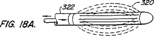
別の半径方向に拡大可能な保持構造が図18Aから図18Cに示してある。スロット付きの卵管保持構造320は短くなっており、卵管内で拡大する。一般的に、この拡大は外力(例えば、2部分式送り出しシステム322の起動)の結果であり得る。あるいは、保持構造は、その場で解放されたときに、自己拡大するものであってもよい。強制的に拡大させられた保持構造は、卵管内の送り出しシステムから器具を取り外したときに崩壊を防ぐ係止機構を持っていてもよい。このような取り外しは上記の機構のいずれによっても実施することができる。
【0093】
螺旋形の二次コイル204およびスロット付きの卵管保持構造320の代わりに、またさらに別の保持構造を使用することができる。例えば、Malecott保持構造324または編んだフィラメント保持構造326を拡大させて周囲の卵管壁と係合させてもよい。いくつかのケースにおいて、卵管固定は、少なくとも2つの保持構造を設けるか、あるいは、軸線方向移動を防ぐように拡大した保持構造から軸線方向あるいは半径方向またはこれら両方向に延びる小さなさかとげを設けることによって、強化することができる。好ましくは、このようなさかとげは、卵管壁を突き通るには短すぎるであろう。本発明の卵管内避妊具において保持構造として使用するようになっている多種多様な別の半径方向拡大可能な構造を脈管ステントに関して説明する。
【0094】
形状記憶合金からなる保持構造を有する卵管内器具が図19A、図19Bに示してある。一般に、システムは、器具が低プロファイル(送り出しのため)から展開プロファイルに拡大して所定位置に保持されるように、避妊具にエネルギを付与する。器具は、一次コイル202に2つの電気絶縁された導体に沿って電流を送ることによって加熱され得る。ここでは、コアワイヤ152は絶縁層271を有し、コイルの第1部分に接続してある。一方、送り出しカテーテル256の導体269はコイルの他の部分に接続している。小電流に対するコイルの抵抗は、保持構造を加熱、再構築するのに十分である。エネルギ源内の共通の9ボルト手持ち式電池からの電気エネルギは二次コイル204を再構築するのに十分である。二次コイルは、本体温度でほぼ展開された形態に留まる。別のシステム、加熱した塩水等も使用し得る。
【0095】
上述したように、銅は卵管内避妊具400の効力を強化できる。図20A、図20Bに示すように、銅体(例えば、銅製コイル402の形をしている)は、卵管から子宮・卵管接合部内へあるいはそれを貫いて近位方向に延在し得る。図21A、図21Cでわかるように、あるいは、銅は、ボンド、内殖構造等を形成するのに使用し得る銅ビーズ404の形をしていてもよい。銅は、一次コイル、二次コイル等で使用するためのコア材料408に施したメッキ406の形をしていてもよい。
【0096】
銅の放出率は、しばしば、器具上の銅の表面積に密接に関係する。100mm2以上である全銅表面積、最も頻繁には、約300mm2 から約400mm2の範囲にある全銅表面積が避妊を行うには好ましい。
【0097】
銅の全体積は、銅が与える効力向上の持続時間に影響を及ぼす。生涯避妊を行うためには、約25年間(女性の生殖寿命に基づく)にわたって充分な銅を提供しなければならない。400mm2の露出銅表面積の場合、平均銅放出率は、子宮内避妊具の研究に基づけば、毎日あたり約25マイクログラムであればよい。本発明の卵管内避妊具を25年間にわたってこの率で銅を放出させるには、少なくとも0.23グラムまたは25.6mm3の銅を含むと好ましい。合理的安全ファクタを得るためには、25年器具は、少なくとも約0.34グラムまたは38.4mm2の銅体積を含むとよい。これらの量は、各器具毎に、または、2つの器具(左右の卵管用)の組合せ毎に与えることができる。同様の計算を、5年用器具(同じ露出面積を使用し、少なくとも1/5の体積を使用する)を行ってもよいし、または、卵管の異なった領域に担持される銅構造から生じる異なった放出/面積効力について調節を行ってもよい。
【0098】
結論として、本発明は、手術なしに位置決めすることができる避妊用卵管内器具を提供する。上記では本発明の好ましい実施例を完全に説明したが、種々の代替物、変形例、均等物を使用し得る。例えば、開ループ、連続する湾曲、正弦波カーブ等を含む広範囲にわたって異なる二次形状を一次コイルに付与することができる。それに加えて、個別に説明した卵管内避妊具の特徴は、しばしば、組み合わせることができる(例えば、自己案内式器具は、卵管内に器具を取り付けるために内殖を促進することもできる)。したがって、上記の説明は発明の範囲を限定するものではなく、発明の範囲は添付の特許請求の範囲によってのみ定義されるべきである。
【図面の簡単な説明】
【図1】 本発明による避妊用卵管内器具の第1実施例を示している。
【図2】 図1の避妊用卵管内器具において使用される一次コイルを示している。
【図3】 図1の避妊用卵管内器具において用いられるような一次コイル上に設けた二次コイルを示している。
【図4】 図1の避妊用卵管内器具と共に使用するコアワイヤを示している。
【図5】 図1の避妊用卵管内器具を有する避妊用送り出しシステムの断面図である。
【図6】 本発明の避妊用卵管内器具の別の実施例を示している。
【図7】 図6の避妊用卵管内器具において使用される一次コイルを示している。
【図8】 図6の避妊用卵管内器具を包含している避妊用送り出しシステムを概略的に示している。
【図9】 本発明による避妊用卵管内器具の送り出し方法を示している。
【図10】 本発明による避妊用卵管内器具の送り出し方法を示している。
【図11】 A〜Dは、付随する送り出し器具、システムと共に、まっすぐな一次コイルを有する卵管内避妊具を示している。
【図12】 A〜Eは、卵管内避妊具の避妊効力を向上させる組織反応を促進するようになっている様々な卵管内避妊具を示している。
【図13】 避妊具の螺旋形のコイル内へ繊維材料の細い組紐を導入する方法を示している。
【図14】 卵管内への避妊具の保持を強化するように種々の卵管サイズに適応する螺旋形のコイルを示している。
【図15】 A〜Dは、半径方向に拡大可能な螺旋形のコイルを有する避妊具の送り出し前、送り出し中、送り出し後をそれぞれ示す、卵管を通る断面図を示しており、また、螺旋形コイル内への、そして、そのまわりへの組織内殖のような組織反応によって得られる効力向上も示している。
【図15E】 まっすぐな一次コイルを有する避妊具の自己案内能力を示している。
【図16】 取り外し可能な遠位コアワイヤを有する避妊用送り出しシステムを示している。
【図17】 避妊用送り出しシステムおよび使用説明書を包含するキットを概略的に示している。
【図18】 A〜Cは、卵管内に避妊具を機械的に固定できる別の管状半径方向拡大可能保持構造を概略的に示している。
【図19】 A、Bは、保持構造の形状記憶合金を加熱する電流を伝送することによって手持ち式電池が保持構造を電気的に作動させる卵管内避妊システムを示している。
【図20】 A、Bは、子宮・卵管接合部内に銅からなるコイルを支えるのに使用する卵管内避妊具、方法を示している。
【図21】 A〜Cは、本発明の原理に従って受胎を阻害するのに使用する銅製の別の構造および方法を示している。[0001]
(Field of Invention)
The present invention relates generally to contraception, and more particularly,It relates to a contraceptive device in the fallopian tube.
[0002]
Safe and effective methods for contraception and permanent sterilization are in demand around the world. Although various contraceptive and sterilization methods are available, all existing methods have limitations and drawbacks. Therefore, the need for safer, lower cost and reliable contraceptive and permanent sterilization methods is widely recognized in both developed and developing countries.
[0003]
Many currently available contraceptive methods require significant user participation. And user disapproval makes the failure rate very high. Although the theoretical effectiveness of existing contraceptives, including barrier methods and hormonal therapies, is well established, it has proven difficult to overcome user disapproval to improve overall efficacy .
[0004]
One form of contraception that is less affected by user non-conformity is an intrauterine device (IUD). IUD has been found to be more reliable and effective over the long term than most other commercially available contraceptives. Unfortunately, IUD is also associated with significant infectious complications. For this reason, the use of IUD in the United States has decreased dramatically. In addition, IUD is prone to unexpected exudation and must be removed due to excessive pain and bleeding in a certain percentage of cases, further reducing the acceptance of IUD as a contraceptive. Interestingly, the potency of copper IUD seems to be higher than that of non-metallic IUD. The reason has not been fully explained.
[0005]
Commercial options for permanent sterilization include tubal ligation and vasectomy. These methods are surgical, difficult to reverse, and are not available to many people around the world. It is common sense that fertilization occurs in the oviduct where sperm and ovum meet. Fallopian tube ligation avoids fertilization by complete occlusion of the fallopian tube.
[0006]
It has heretofore been proposed to reversibly occlude the oviduct. For example, it has been proposed to form an elastomeric plug in vitro or to fix the device on either side of the narrowest area of the fallopian tube (referred to as the “strait”). Although such oviductal occlusion methods appear promising, a fairly high percentage of the non-surgical devices proposed to date have been eliminated in subsequent studies. Even if non-surgical endotubal devices remain, it has been found to be only as effective as preventing fertility.
[0007]
For these reasons, it is desirable to have an in-vitro device that is effective and reliable for contraception and sterilization. It is particularly desirable to have a very effective in-vitro device that does not require surgery for installation. It is particularly desirable that such devices and methods can facilitate device placement and are less squeezed than previously proposed non-surgical intratubal devices.
[0008]
(Description of related technology)
The experimental use of stainless steel in-vitro devices is described in “Transcatheter Tubal Sterilization in Rabbits” by Penny L. Ross in RT29 “Investigative Radiology” pp. 570-573 (1994). The experimental use of pure copper wire as an electrolyte as an in-vitro device for surgical contraception in rats has been described by D. N. Gupta in 14 Indian Journal of Experimental Biology, pp. 316-319 (May 1976). Antifertility Effect of an Intrafallopian Tubal Copper Device ”.
[0009]
British Patent Application No. 2,211,095 describes a uterine screw plug for occluding an oviduct. European Patent Application Publication No. 0,010,812 describes an oviductal installation device having enlarged portions at both ends for fixation. The same device seems to be described in Dutch Patent 7,810,696.
[0010]
The use of the fallopian tube occlusion device is a co-author of The Journal of Reproductive Medicine, pp. 65-68 (August 1979), Robert A. Erb, Ph.D. "It is described in. A formed-in-place elastomeric fallopian tube occlusion device is described in US Pat. No. 3,805,767 issued to Erb. US Pat. No. 5,065,751 issued to Wolf describes a method and apparatus for reversibly occluding a biological fallopian tube. U.S. Pat. No. 4,612,924 issued to Cimber describes an intrauterine contraceptive device that seals the mouth of the fallopian tube.
[0011]
German Patent 2,803,685 issued to Brundin describes a device for plugging a human tube with a device that swells when in contact with bodily fluids.
An alternative contraceptive device is described in co-pending US patent application Ser. No. 08 / 474,777. The entire disclosure of this US patent is incorporated herein by reference.
[0012]
(Summary of Invention)
The present invention provides an in-vitro apparatus and method that is installed to prevent conception. The intraoviductal device of the present invention is delivered across the neck into the fallopian tube without the need for surgical treatment or the risk of increased bleeding, pain, infection associated with an intrauterine device (IUD), It is mechanically fixed in it and performs long-term contraception or permanent sterilization.
[0013]
The intraoviductal device of the present invention often consists of a structure having a transluminal region with a helical outer surface. The helical surface forms an enlarged secondary shape, preferably mechanically secured by a resilient portion of the structure that is biased to form a distal, proximal securing loop. The fixed loop prevents the helical outer surface from rotating from place and helps to prevent axial movement within the fallopian tube. In another embodiment, the fixation is provided by a straight coil that is elastically biased by the axial curvature of the torsional oviduct, and a radially expandable braid, malecott or other tubular structure attaches the device within the oviduct Can help.
[0014]
When copper is used in the oviduct apparatus of the present invention, the efficacy as a contraceptive method is improved. However, devices formed from plastically deformable materials cannot be easily constrained within the fallopian tube. Obviously, the actual shape and dimensions of the fallopian tubes vary considerably, making it impossible to provide a reliable fixation for a preformed deformable intratubal device. Thus, the in-vitro device of the present invention often includes a resilient structure, usually a metal coil. The metal can be a copper alloy or plating, ideally an alloy containing at least 75% copper. Typical coil materials include beryllium, zinc, stainless steel, platinum, and shape memory alloys (eg, Nitinol (registered trademark)). Preferably, the coil is made of an alloy of beryllium and copper.
[0015]
Although the device of the present invention will substantially occlude, it is not necessary to occlude the fallopian tube completely to prevent sperm and eggs from meeting. Instead, in some embodiments, the presence of copper on a resilient structure is sufficient for effective contraception. Therefore, despite the presence of an open lumen, contraception can be performed by disrupting the normal structure and / or function of the fallopian tube. This concept is referred to herein as “functional occlusion”. As used herein, functional occlusion means that when implanted in the fallopian tube, the device disrupts the normal structure and / or function of the fallopian tube and inhibits fertilization and / or conception.
[0016]
Conveniently, the present invention further includes non-surgical placement of such an intratubal device by transcervical introduction. The resilient structure can be constrained to a straight configuration using, for example, a core wire, which considerably facilitates introduction and significantly reduces the risks associated therewith. Thus, the costs and risks associated with existing surgical contraception and sterilization operations are avoided. A resilient structure often consists of a coil. In some embodiments, an element is placed along the coil to cause a tissue reaction of fallopian tube tissue that prohibits conception. The distal anchor of the coil can be inserted into an ampler distal to the isthmus, while the proximal anchor is located at the fallopian tube. These anchors help prevent device rotation and avoid axial movement. Alternatively, depending on the length and form, at least one of these anchors may be installed at an arbitrary position in the fallopian tube past the fallopian mouth, and the other may be extended into the uterus. Preferably, at least some kind of fixation is performed along the fallopian tube wall up to the canal region of the fallopian tube. In some embodiments, electrosurgical attachment of the endoluminal device to the surrounding lumen wall can provide effective fixation without loops and other fixation structures. Electrical current can also be used to disconnect the in-vitro device from the delivery system, typically by electrolyzing solder bonds. The current can also activate the anchor. For example, a flexible radially expandable tubular structure within the fallopian tube can be released.
[0017]
The present invention also provides an improved contraceptive device that produces a tissue reaction in the fallopian tube to prevent conception. This group of device in the fallopian tube often uses a very flexible coil structure to prevent damaging or penetrating the delicate fallopian tube tissue. The desired tissue reaction may be the result of the material of the in-vitro device or may be caused by coating, surface treatment, or mechanical interaction of the device with the surrounding oviduct wall. Tissue often interferes with conception by tubal obstruction, blockage of the transport mechanism of the tubal tissue, intratubal restraint of the intratubal device, and the like. Specific tissue reactions that can provide these intended results include tissue in-growth in contraceptive devices and / or fallopian tubes, scar tissue formation, and stiffening of fallopian tube tissue.
[0018]
According to one aspect, the present invention provides a tissue responsive contraceptive device for use in an oviduct. This contraceptive device comprises a coil having a proximal end and a distal end and defining an axis between these ends. The coil is axially flexible and has a cross-section suitable for insertion into the fallopian tube. Elements placed along the coil cause a tissue reaction in the fallopian tube tissue adjacent to the coil and inhibit fertility.
[0019]
In some embodiments,Internal growth promotion elementsCan promote the in-growth of fallopian tube tissue into the contraceptive device. For example,Internal growth promotion elementsAs knitted or woven polyester, microporous material or surface treatment. Alternatively, a spiral ribbon or other mechanical interaction element with sharp edges can cause the formation of scar tissue, or the surface coating of the coil stiffens the fallopian tube tissue and interferes with conception transport It is possible to promote the formation of a strong fibrous connective tissue. In many embodiments, the presence of a contraceptive device combined with a tissue reaction can provide effective contraception without relying on complete occlusion of the fallopian tube.
[0020]
According to another feature, the present invention provides a tissue in-growth contraceptive device for use with an oviduct. The contraceptive device consists of a tubular retaining structure having a proximal end, a distal end and an axis between these ends. This holding structure is flexible in the axial direction and can be inserted into the fallopian tube. A material capable of causing tubal tissue ingrowth is attached to and exposed radially from the retaining structure.
[0021]
In an exemplary embodiment, the retention structure includes a helical coil having an ingrowth material disposed thereon. Such helical coils can optionally be expanded radially within the fallopian tube, therebyContraceptiveCan be adapted to a wide variety of oviduct physiological conditions. The ingrowth material may be in the form of knitted or woven fibers such as polyester or PTFE.
[0022]
In another aspect, the present invention provides a tissue in-growth contraceptive device for use with an oviduct. This contraceptive device has a proximal end and a distal end, and defines an axis between these endsElongated elasticConsists of a body. Holding structureThe aboveArranged along a flexible body. This holding structure is designed to restrain the elastic body in the fallopian tube. Bond attaches the retaining structure to the elastic body. Resilient body, retaining structure,and,Out of bondofAt least one is made of a microporous material that promotes tissue ingrowth.
[0023]
In connection with the present invention,A contraceptive method consisting of inserting a contraceptive device into the fallopian tube in a cross-cervical mannerDisclose.The contraceptive isContraceptiveElastically bias the distal body against the fallopian wall, along the fallopian tubeThe aboveA distal body guides the contraceptive device. Tissue reactions are caused by elements of the contraceptive device within the fallopian tube tissue. This tissue reaction attaches a contraceptive device within the fallopian tube.
[0024]
The present invention also provides improved contraceptive devices, systems and methods adapted for use with a wide range of shapes and dimensions of the fallopian tubes. By recognizing a wide range of physiological changes in the fallopian tubes, the contraceptive structure of the present invention can expand radially within the fallopian tube and engage the fallopian tube wall. Surprisingly, the contraceptive device of the present invention often uses a tubular structure such as a resilient helical coil. Such tubular devices often do contraception by breaking the structure and / or transport mechanism of the fallopian tube tissue rather than completely closing the fallopian tube. The passage through the tubular contraceptive device of the present invention is optionally occluded by promoting tissue ingrowth within the device, for example by including knitted or woven polyester fibers in a helical coil. Can do. In any case, such a tubular retaining structure can be expanded radially toward the fallopian tube wall over a wide range of fallopian tube sizes to safely secure the contraceptive device without resorting to protruding barbs or the like. it can.
[0025]
According to one aspect, the present invention provides a contraceptive device for use with an oviduct having an oviduct wall. The contraceptive device includes a tubular retaining structure having a proximal end, a distal end, and an axis between these ends. The retention structure expands radially in situ from the narrow configuration to form a second expanded diameter (in this case, the retention structure is a first diameter suitable for axial insertion into the oviduct). Have). The enlarged retaining structure engages the surrounding fallopian tube wall to hold the contraceptive device within the fallopian tube.
[0026]
According to another feature, the present invention provides a contraceptive device for use with an oviduct having an oviduct wall. The contraceptive device includes a fertility inhibitor that constitutes an axis. A helical coil is placed around the fertility inhibitor. A portion of this helical coil can move relative to the fertility inhibitor, allowing the helical coil to elastically expand over a range of oviduct cross-sectional sizes. Therefore, the coil can engage radially with the surrounding fallopian tube wall and the contraceptive device can be safely mounted in the fallopian tube.
[0027]
The present invention also provides an intratubal contraceptive device having an elongated coil that is substantially straight. Surprisingly, when such a straight coil is placed axially in a tortuous fallopian tube, the coil bend forced by the fallopian tube can cause the coil to be elastically secured. Such straight coils are also very advantageous when a contraceptive device is advanced into (and within) the fallopian tube. The straight resilient coil can act as an integral guide wire during transcervical deployment of the instrument in the fallopian tube. Thereby, delays that occur when a guide wire, fallopian tube catheter, etc. must be used subsequently can be avoided.
[0028]
The present invention provides an intraoviduct contraceptive device for use in an oviduct. The contraceptive device includes an elongated coil having a proximal end, a distal end, and an axis between the ends. When the coil is stationary, the axis is almost straight. And the coil is elastic in the axial direction, facilitating the insertion of the fertility inhibitor into the fallopian tube in the axial direction. The contraceptive device is held in the fallopian tube to inhibit conception.
[0029]
According to another feature, the present invention provides an intratubal contraceptive device for use with an oviduct. The wall of the fallopian tube has a fallopian tube cross section and an axial bend. The contraceptive device includes an elongated body having a proximal end and a distal end and defining an axis between the ends. This elongate body has a cross section suitable for axial insertion within the fallopian tube cross section. At least a portion of the elongate body is straighter than the axial curvature of the fallopian tube. The elongated body is sufficiently flexible to bias against the fallopian tube wall without damaging the fallopian tube wall. The elongate body is also sufficiently resilient to apply a locking force against the wall of the fallopian tube when the straight portion is deflected along the fall of the fallopian tube.
[0030]
According to another feature, the present invention provides a contraceptive device for use with an oviduct having an axis. The contraceptive device includes a structure having a proximal end, a distal end and an axis between these ends. When placed approximately coaxially within the fallopian tube, this structure is designed to provide effective fallopian tube occlusion. An elongate member is attached to the occlusion structure, the elongate member being sufficiently flexible and resilient in the axial direction to guide it as it is advanced distally within the fallopian tube. To help.
[0031]
According to the present inventionRelatedIn the contraceptive method, an elongated elastic body is inserted across the neck into an oviduct that is curved in the axial direction. The curved body provides a securing force that helps to secure the curved body in the fallopian tube. This attached elastic body is secured in the fallopian tube to inhibit conception.
[0032]
In connection with the present invention,A contraceptive method comprising the step of inserting an intra-oviduct contraceptive device along the fallopian tube in a transcervical manner by guiding the contraceptive device with a distal guide-wire-like structure of the contraceptive deviceDisclose.The contraceptive device, including at least a portion of the guide wire-like structure, is retained in the fallopian tube to inhibit conception.
[0033]
According to another feature, the present invention provides a contraceptive kit. thisContraceptiveThe kit includes an oviduct contraceptive and instructions for use.SaidThe instructions for use describe the steps of introducing the contraceptive device into the fallopian tube in a transcervical manner and attaching the contraceptive device into the fallopian tube. Optionally, various delivery structures including guide wires, core wires, delivery catheters, etc. can also be provided in the kit.
[0034]
According to yet another aspect, the present invention provides an intratubal contraceptive system that includes an elongated delivery body having a proximal end and a distal end. A first energy conduit extends between the proximal and distal ends, and the intratubal structure near the distal end has a first cross section. An energy source is connected to this intratubal structure by a first conduit. The energy from this energy source constrains the structure in the fallopian tube to the second cross-section, restrains the structure in the fallopian tube, and inhibits conception.
[0035]
According to a last feature, the present invention includes a first end having a proximal end, a distal end, and extending between the proximal end and the distal end.Conductor, Providing an elongated delivery body having a second conductor. Contraceptive structure in the fallopian tubeSaidNear the distal end of the delivery body. FirstConductorThe power supply by the second conductorSaidCan be connected to intratubal contraceptive structures. This advantageous bipolar arrangement is, for example,Contraceptive structure in the fallopian tubeThe shape memory alloy structure can be activated by transmitting current from the handheld battery through at least a portion of the battery.
[0036]
(Detailed description of examples)
The present invention includes contraceptive intratubal devices that can be used alternately as both permanent contraceptive means and reversible contraceptive means.Related to the present inventionContraceptive methods andOf the present inventionContraceptive devices minimize the risk of non-use that has limited the effectiveness of conventional contraceptive techniques. Furthermore, installation of the device of the present invention in the fallopian tube reduces the risk of contagious complications, increased bleeding and pelvic pain associated with intrauterine contraceptive devices (IUD). The installation and novel shape of the in-vitro device of the present invention provides significant advantages over the IUD. It has been found that IUD often has to be unscheduled and removed due to excessive pain and bleeding. The present invention takes advantage of the increased effects associated with copper IUDs and provides a resilient structure comprising copper that can be placed across the neck without the need for surgery.
[0037]
Related to the present inventionContraceptive methods are included within a group of contraceptive techniques commonly referred to as tubal occlusion methods,This method of contraceptionIt does not necessarily rely solely on occluding the fallopian tube to prevent fertilization. Instead, it is clear that contraception is performed by breaking egg transport, fertilization processes, egg cleavage, etc. Although the effects of copper on these processes are not fully understood, copper in-vitro devices are potentially more effective than in-vitro devices made of other materials. Alternatively, contraception can be performed or enhanced by a spermicide attached to the device. Optionally, the invention further includes a device that promotes tissue growth in the fallopian tube to induce obstruction of the fallopian tube and further inhibits conception. In some embodiments, polyester fibers such as Dacron®, Rayon®, etc. are bonded to the surface of the coil using a polymer adhesive. Polyester fibers promote tissue growth around the coil and further reduce the possibility of the device being squeezed out of the fallopian tube.
[0038]
Conveniently, the resilient structure of the present invention is releasably attached via a core wire, which constrains the resilient structure to a straight configuration. When in a straight configuration, this resilient structure has an outer diameter that is smaller than the inner diameter of the fallopian tube, so that a catheter containing the in-vitro device of the present invention can be easily introduced across the neck.
[0039]
The present invention can be secured within the canal of the fallopian tube. This overcomes unintentional contraceptive pumping and the resulting failure of the contraceptive method. Such in-vitro device extrusion was the single largest factor limiting the efficacy of in-vitro contraceptive technology that is easy to install. The intraoviductal device of the present invention is a generally elongate elastic structure preformed in a secondary shape. These secondary shapes will preferably form anchors in the proximal and distal directions of the thinnest part of the fallopian tube (called the gorge). The secondary shape preferably has an outer diameter that is larger than the inner diameter of the isthmus. Fixation is also possible across the other parts of the fallopian tube lumen, often between the fallopian mouth and the isthmus.
[0040]
The device of the present invention generally moves the elastic structure near the proximal end and pulls it in the proximal direction of the elastic structure so that the elastic structure can be straightened and pulled out. It can be easily removed without causing damage. Alternatively, after the instrument is placed in the fallopian tube, a current is applied to the instrument to effect permanent sterilization. The current may also be effective in separating the instrument from the delivery system using a system similar to that described in US Pat. No. 5,624,449. The entire disclosure of this US patent is incorporated herein by reference. In-situ activation of the anchor can either release the elastic structure in a similar mechanism and expand it in-situ, or by current-induced phase changes in the shape memory alloy (eg, Nitinol® straightened by current Can be done by curling the ribbon in the fallopian tube).
[0041]
Hereinafter, referring to FIG. 1, the first embodiment of the contraceptive intratubal device 10 of the present invention is formed from a resilient
[0042]
The
[0043]
Hereinafter, referring to FIG. 2, the
[0044]
Preferably, the
[0045]
The
[0046]
In the following, referring to FIG. 3, the proximal and distal anchors are formed by imparting a bent secondary shape to selected portions of the
[0047]
Referring now to FIG. 4, the
[0048]
In the following, referring to FIG. 5, the intratubal
[0049]
Referring now to FIG. 6, another embodiment of the in-vitro device of the present invention is again formed from a resilient
[0050]
Hereinafter, referring to FIG. 7, the
[0051]
Referring now to FIG. 8, an intra-oviduct contraceptive system using another
[0052]
The use of the contraceptive intratubal device of the present invention is illustrated in FIG.FigureThis will be described with reference to FIG.
[0053]
The intratubal
[0054]
Once the in-vitro device 10 is properly positioned, torque is applied to the
[0055]
The present invention further provides permanent sterilization by passing an electrical current through the core wire through the in-vitro device prior to withdrawing the core wire. The fallopian tube tissue in contact with the in-vitro device is dried and attached to the in-vitro device of the present invention. This operation also causes permanent damage to the fallopian tube, which forms scar tissue that encloses the endotubal device, resulting in permanent occlusion of the fallopian tube lumen. Clearly, the core wire / primary coil interface must be electrically conductive to allow the non-surgical permanent sterilization method according to the present invention.
[0056]
Related to the present inventionIntratubal contraception andContraceptive device of the present inventionCan provide very effective contraception even when the contraceptive device does not completely occlude the lumen of the fallopian tube. In order to minimize the bloating of delicate fallopian tube tissue, the present invention often leaves a slightly open lumen in the fallopian tube when deployed at least for the first time. In fact, these contraceptive devices often include a perforated tubular structure having a lumen. Nevertheless, despite the presence of an open lumen, contraception can be performed by breaking the normal structure and / or function of the fallopian tube. This concept is referred to herein as “functional occlusion”. As used herein, a functional occlusion device means a device that, when implanted in the fallopian tube, disrupts the normal structure and / or function of the fallopian tube and inhibits fertilization and / or conception. .
[0057]
The size of the closure device required to provide a functional occlusion may depend on the material of the device, the location where the device is being deployed without the fallopian tube, the interaction of the device with the surrounding fallopian tube wall, and the like. For example, an intra-oviduct contraceptive structure that includes polyester fibers can result in the in-growth of fallopian tube tissue into the device. As a result of this tissue / instrument interaction, relatively small instruments that promote ingrowth can provide effective occlusion. In fact, such a device can provide complete occlusion by causing sufficient ingrowth, so that the proliferative flaming oviduct wall combined with this device can pass all passages through the lumen of the fallopian tube. Occlude. Therefore, the structure is relatively small and easy to insert, and can effectively prevent conception without bloating the fallopian tube wall.
[0058]
One easy-to-insert intratubal contraceptive structure that can provide effective oviduct occlusion is shown in FIG. 11A. The straight
[0059]
The
[0060]
In an exemplary embodiment, straightContraceptive200 is about 3.0from cmIt includes a
[0061]
Hereinafter, FIG.FigureReferring to FIG. 11C, the self-guided
[0062]
Advantageously, the
[0063]
Contraceptive200Can be easily delivered by using a core wire having a relatively long, rigid proximal portion and a relatively short, flexible portion. This flexible portion is typically tapered as shown. The thickness and material of these parts is such that the
[0064]
The
[0065]
According to a particularly advantageous feature, the
[0066]
Still further capabilities may be incorporated into the delivery system. For example, a “smart” delivery device can detect its position in the fallopian tube magnetically, electrically, optically, ultrasonically, etc. Similarly, deployed instruments can incorporate structures that allow a physician to remotely examine the location and presence of the instrument without accessing the fallopian tube (eg, using a magnetic sensor, impedance and / or radio activity). .
[0067]
In an exemplary embodiment, the
[0068]
One way of attaching the
[0069]
A wide variety of other mechanisms can be used to produce a tissue response that enhances the functional occlusion of the intratubal contraceptive device. For example, materials such as collagen, hydroxyapatite, solid or fibrous PTFE can be used. The biodegradable coating may cause tissue ingrowth or scarring and then degenerate to leave a completely or partially occluded lumen. In some embodiments, the engagement between the
[0070]
Various alternatives for in-vitro-enhanced fallopian contraceptive devices are shown in FIG.To FIG. 12EIt is shown in In general, theseContraceptiveEach includes certain elements that promote tubal tissue ingrowth. The porous
[0071]
In some embodiments,
[0072]
Still other in-growth promoting elements such as
[0073]
In the following, referring to FIG. 13, a particularly advantageous method of a contraceptive device having a
[0074]
The use of a
[0075]
Yet another in-vitro contraceptive device 200 'is shown in FIG. This device 200 'includes some of the same main structures described above with respect to the straight
[0076]
Another
[0077]
A tubular holding structure that is greatly expandable in the radial direction has several significant advantages. First, the structure can be inserted in a narrow profile configuration and provided with a anchor anchor while minimizing the risk of being radially expanded within the fallopian tube and penetrating through the delicate fallopian tube wall. In addition, the rigidity of the helical secondary coil provides appropriate engagement and / or damage to the oviduct wall tissue to produce the desired tissue response in any scar tissue formation, ingrowth, etc. Can be configured. The outer diameter can also be adjusted during delivery by applying torque to the helical coil with a free end.
[0078]
The great variability in outer diameter provided by the
[0079]
14B,14C.As shown, the contraceptive device can be constrained to a small diameter configuration by a
[0080]
Another helical holding structure is shown in FIGS. 14D and 14E. The tapered
[0081]
Another structure for releasably restraining the
[0082]
Prior to delivery,
[0083]
Once the instrument is positioned, rotate the core wire and the proximal portion of the catheter relative to each other (by releasing the Tohey-Borst valve etc.) or actively rotate one of these structures Or both can be done to unwind the secondary coil and allow the
[0084]
Yet another release mechanism is possible, including the system shown in FIG. 14H. A proximally inwardly tapered body or brake 265 is attached to the
[0085]
The importance of tissue reaction in performing tubular occlusally expandable intra-oviductal devices and functional occlusion is illustrated in FIG. 15A.To FIG. 15DFor further understanding. The lumen L of the fallopian tube F is a potential space, much like a deflated balloon. The oviduct wall W can expand around a structure that is inserted into the lumen L, such as around a
[0086]
In work in connection with the present invention, it has been found that the fallopian tube can vary considerably in inner lumen cross-sectional size. The maximum diameter of the instrument that the fallopian tube can accommodate in its smallest part is 0.2From mmIt can be anywhere from 1.5 mm. For instruments having a constant cross-section, the relatively large diameter makes delivery of the instrument more difficult. However, if the device is too small, it tends to be released from the fallopian tube. Although certain cross-section instruments may still be effective (eg, by providing a range of different instrument sizes), a radially expandable tubular structure such as a
[0087]
As generally described above, the
Despite the fallopian wall tissue protruding between the turns of the
[0088]
As can be understood with reference to FIGS. 15D and 16, the open area in the contraceptive device along the axis of the fallopian tube F has some potential to provide a passage for fertilization. In order to avoid providing a prosthetic lumen constituted by the inner surface of the
[0089]
The use of the primary coil 202 (in combination with the core wire 214) as a guide wire can be understood with reference to FIG. 15E. The good proximal column strength of the core wire and the combined core wire at the distal end of the delivery device, increased flexibility in the distal direction of the primary coil, facilitates the advancement of the instrument within the fallopian tube F. The ability of the
[0090]
Referring now to FIG. 17,
[0091]
The
[0092]
Another radially expandable retention structure is shown in FIG. 18A.To FIG. 18CIt is shown in Slotted fallopian tube holding structure320Is shortened and expands in the fallopian tube. In general, this expansion can be the result of an external force (eg, activation of the two-part delivery system 322). Alternatively, the retaining structure may be self-expanding when released in place. The forcefully expanded retention structure may have a locking mechanism that prevents collapse when the instrument is removed from the delivery system in the fallopian tube. Such removal can be performed by any of the mechanisms described above.
[0093]
Helical
[0094]
FIG. 19A shows a device in a fallopian tube having a holding structure made of a shape memory alloy.FIG. 19BIt is shown in In general, the system energizes the contraceptive device so that the device is scaled from a low profile (for delivery) to a deployed profile and held in place. The instrument can be heated by sending current to the
[0095]
As described above, copper can enhance the efficacy of the intratubal contraceptive device 400.20A and 20BAs shown, the copper body (eg, in the form of a copper coil 402) may extend proximally from the fallopian tube into or through the uterine-fallopian junction. FIG.FIG.Alternatively, the copper may be in the form of
[0096]
Copper release rate is often closely related to the surface area of copper on the instrument. 100mm2more thanIs the total copper surface area,Most often, about 300mm2 FromAbout 400mm2A total copper surface area in the range is preferred for contraception.
[0097]
The total volume of copper affects the duration of potency gain given by copper. For lifelong contraception, enough copper must be provided for approximately 25 years (based on the female reproductive life). 400mm2For an exposed copper surface area, the average copper release rate may be about 25 micrograms per day based on intrauterine device studies. At least 0.23 grams or 25.6 mm for the intra-oviduct contraceptive device of the present invention to release copper at this rate over 25 yearsThreeIt is preferable to contain copper. To obtain a reasonable safety factor, a 25-year instrument should be at least about 0.34 grams or 38.4 mm2It is good that the copper volume of this is included. These amounts can be given for each instrument or for each combination of two instruments (for left and right fallopian tubes). Similar calculations may be made for 5-year instruments (using the same exposed area and using at least 1/5 volume) or resulting from copper structures carried in different areas of the fallopian tube Adjustments may be made for different release / area efficacy.
[0098]
In conclusion, the present invention provides contraceptive intratubal devices that can be positioned without surgery. While the above is a complete description of the preferred embodiment of the invention, various alternatives, modifications and equivalents may be used. For example, different secondary shapes can be imparted to the primary coil over a wide range including open loops, continuous curves, sinusoidal curves, and the like. In addition, the features of the in-vitro contraceptive devices described individually can often be combined (e.g., self-guided devices can also promote in-growth for mounting devices in the oviduct). Therefore, the above description does not limit the scope of the invention.ClaimsShould only be defined by
[Brief description of the drawings]
1 shows a first embodiment of a contraceptive in-vitro device according to the invention.
FIG. 2 shows a primary coil used in the contraceptive intratubal device of FIG.
FIG. 3 shows a secondary coil provided on the primary coil as used in the contraceptive intratubal device of FIG.
FIG. 4 shows a core wire for use with the contraceptive in tubal device of FIG.
FIG. 5 is a cross-sectional view of a contraceptive delivery system having the contraceptive intratubal device of FIG.
FIG. 6 shows another embodiment of the contraceptive intratubal device of the present invention.
7 shows a primary coil used in the contraceptive intratubal device of FIG. 6. FIG.
FIG. 8 schematically illustrates a contraceptive delivery system that includes the contraceptive in-vitro device of FIG. 6;
FIG. 9 shows a method of delivering a contraceptive intraocular device according to the present invention.
FIG. 10 illustrates a method for delivering a contraceptive intraocular device according to the present invention.
11A-D show an intratubal contraceptive device having a straight primary coil, along with associated delivery devices and systems.
FIGS. 12A-E illustrate various in-vitro contraceptive devices adapted to promote tissue reactions that enhance the contraceptive efficacy of in-vitro contraceptive devices. FIGS.
FIG. 13 illustrates a method for introducing a thin braid of fibrous material into a spiral coil of a contraceptive device.
FIG. 14 shows a helical coil that accommodates various fallopian tube sizes to enhance retention of the contraceptive device within the fallopian tube.
FIGS. 15A-15D show cross-sectional views through the fallopian tube showing a contraceptive device having a spiral coil that is radially expandable before, during, and after delivery; It also shows the increased efficacy obtained by tissue reactions such as tissue ingrowth into and around the shape coil.
FIG. 15E illustrates the self-guiding capability of a contraceptive device having a straight primary coil.
FIG. 16 illustrates a contraceptive delivery system having a removable distal core wire.
FIG. 17 schematically illustrates a kit including a contraceptive delivery system and instructions for use.
FIGS. 18A-C schematically illustrate another tubular radially expandable retention structure that can mechanically secure a contraceptive device within the fallopian tube.
FIGS. 19A and B show an intra-oviduct contraceptive system in which a hand-held battery electrically activates the retention structure by transmitting a current that heats the shape memory alloy of the retention structure.
FIGS. 20A and 20B show the intratubal contraceptive device and method used to support a coil made of copper in the uterine / tubal junction.
FIGS. 21A-C illustrate alternative structures and methods made of copper used to inhibit conception in accordance with the principles of the present invention.
Claims (38)
送り出す前に第1の横断面において半径方向に拘束され、かつ、近位端および遠位端を有し、かつ、前記近位端と前記遠位端との間に1つの軸線を構成する細長いボデー(12、112、204)を含み、前記細長いボデーは、軸線方向に可撓性であり、かつ、卵管の中に挿入するのに適した横断面を有しており、前記細長いボデーは、軸線に対して拘束されていないときに、第2の大きい横断面に拡大するように付勢され、前記近位端と前記遠位端との間で、ほぼまっすぐに留まるようになっており、
前記避妊具は、さらに、前記細長いボデーに沿って配置されていて、前記細長いボデーに隣接した卵管組織の組織反応を生じさせて受胎を阻害するための内殖促進要素を含み、前記内殖促進要素は、繊維性材料、微孔性材料、鋭い縁、表面コーティングからなるグループから選ばれる、
ことを特徴とする避妊具。A tissue responsive contraceptive device for use with an oviduct having an oviduct tissue,
Elongate that is radially constrained in a first cross-section prior to delivery and has a proximal end and a distal end and defines an axis between the proximal end and the distal end Body (12, 112, 204) , said elongated body being axially flexible and having a cross-section suitable for insertion into an oviduct, said elongated body being When biased to expand to a second large cross-section when unconstrained with respect to the axis, so as to remain substantially straight between the proximal end and the distal end ,
The contraceptive device further includes an in-growth promoting element disposed along the elongated body for causing a tissue reaction of the fallopian tube tissue adjacent to the elongated body to inhibit conception, The facilitating element is selected from the group consisting of fibrous materials, microporous materials, sharp edges, surface coatings,
Contraceptive device characterized by that.
前記内殖促進要素は、編んだあるいは織った繊維を含むことを特徴とする避妊具。The contraceptive device according to claim 1,
The contraceptive device, wherein the ingrowth promoting element includes knitted or woven fibers .
前記内殖促進要素は、卵管組織の組織内殖を促進する表面細孔を構成する微孔性材料からなることを特徴とする避妊具。The contraceptive device according to claim 1,
The contraceptive device, wherein the ingrowth promoting element is made of a microporous material that constitutes surface pores that promote tissue ingrowth of fallopian tube tissue.
前記微孔性材料が、PTFE、セラミック、微孔性重合体からなるグループから選ばれた材料からなることを特徴とする避妊具。The contraceptive device according to claim 3,
The contraceptive device, wherein the microporous material is made of a material selected from the group consisting of PTFE, ceramic, and microporous polymer.
前記内殖促進要素は、卵管組織の瘢痕形成、卵管組織の内殖、卵管組織の硬化うち少なくとも1つを促進させる表面コーティングを含むことを特徴とする避妊具。The contraceptive device according to claim 1,
A contraceptive device characterized in that the ingrowth promoting element includes a surface coating that promotes at least one of scar formation of the fallopian tube tissue, ingrowth of the fallopian tube tissue, and hardening of the fallopian tube tissue.
前記細長いボデーは、保持構造(204)であることを特徴とする避妊具。The contraceptive device according to claim 1,
The contraceptive device, wherein the elongated body is a holding structure (204) .
前記内殖促進要素は、編んだポリエステル、又は、織ったポリエステルからなることを特徴とする避妊具。The contraceptive device according to claim 6,
The contraceptive device, wherein the ingrowth promoting element is made of knitted polyester or woven polyester.
前記保持構造(204)が、少なくとも1つの半径方向の開口を有する孔明き構造を包含し、前記編んだあるいは織ったポリエステルが、前記少なくとも1つの半径方向の開口を通って前記保持構造を越えて半径方向に延びていることを特徴とする避妊具。The contraceptive device according to claim 7,
The retaining structure (204) includes a perforated structure having at least one radial opening, and the knitted or woven polyester passes through the at least one radial opening and beyond the retaining structure. A contraceptive device characterized by extending in the radial direction.
前記保持構造(204)が、鋭い縁を有する螺旋形の外側コイルを包含することを特徴とする避妊具。The contraceptive device according to claim 6,
A contraceptive device wherein the retaining structure (204) includes a helical outer coil having sharp edges.
前記保持構造(204)内に配置した一次コイル(202)を更に包含し、前記内殖促進要素の少なくとも一部が、前記一次コイルと前記保持構造との間にあるループ状スペース内に配置してあることを特徴とする避妊具。The contraceptive device according to claim 6,
Further comprising a primary coil (202) disposed within the retaining structure (204) , wherein at least a portion of the ingrowth promoting element is disposed within a loop-like space between the primary coil and the retaining structure. Contraceptive device characterized by being.
卵管内で軸線方向に避妊具を案内するのを助けるに充分な弾力可撓性をもって前記一次コイル(202)が前記保持構造(204)を越えて遠位方向に延びていることを特徴とする避妊具。The contraceptive device according to claim 10,
The primary coil (202) extends distally beyond the retention structure (204) with sufficient elastic flexibility to help guide the contraceptive device axially within the fallopian tube. Contraceptive device.
さらに、前記一次コイル(202)に前記保持構造(204)を取り付けているボンドを含み、
前記一次コイル、前記保持構造、前記ボンドのうちの少なくとも1つが、組織内殖を促進する微孔性材料からなる、
ことを特徴とする避妊具。The contraceptive device according to claim 10,
And further comprising a bond attaching the retaining structure (204) to the primary coil (202) ;
At least one of the primary coil, the retaining structure, and the bond is made of a microporous material that promotes tissue ingrowth;
Contraceptive device characterized by that.
前記保持構造(204)は、細い直径形態から、その場で半径方向に自己拡大可能であり、細い形態のときの前記保持構造が、卵管内へ軸線方向に挿入するのに適した第1の直径を有し、
拡大したときの前記保持構造が、前記第1の直径より大きい第2の直径を有し、周囲の卵管壁と係合し、卵管内に前記避妊具を保持するようになっている、
ことを特徴とする避妊具。The contraceptive device according to claim 6,
The holding structure (204) is capable of self-expanding in a radial direction on the spot from a narrow diameter form, and the holding structure when in the thin form is suitable for being inserted axially into the fallopian tube. Has a diameter,
The holding structure when expanded has a second diameter greater than the first diameter, and engages a surrounding oviduct wall to hold the contraceptive device in the oviduct;
Contraceptive device characterized by that.
前記保持構造(204)が、弾力的な螺旋形のコイルを包含することを特徴とする避妊具。The contraceptive device according to claim 13,
A contraceptive device, wherein the retaining structure (204) includes a resilient helical coil.
前記弾力的な螺旋形のコイルが、卵管管腔の横断面サイズの範囲全体にわたって卵管壁と安全に係合するように弾力的に拡大することを特徴とする避妊具。The contraceptive device according to claim 14,
A contraceptive device wherein the resilient helical coil elastically expands to safely engage the fallopian tube wall throughout the range of the cross-sectional size of the fallopian tube lumen.
前記弾力的な螺旋形のコイルが、卵管内に前記避妊具を保持する助けとなるには充分であるが、卵管壁を貫通するには不充分である拡大力で、約0.10mmから約1.0mmの範囲を通じて直径を拡げるように弾力的に拡大することを特徴とする避妊具。The contraceptive device according to claim 15,
The resilient helical coil is sufficient to help hold the contraceptive device within the fallopian tube, but with an expanding force that is insufficient to penetrate the fallopian tube wall, from about 0.10 mm to about 1.0 mm. Contraceptive device characterized by elastically expanding to expand its diameter throughout the range.
前記弾力的な螺旋形のコイルが、鋭い外縁を有することを特徴とする避妊具。The contraceptive device according to claim 14,
A contraceptive device characterized in that the elastic helical coil has a sharp outer edge.
前記弾力的な螺旋形のコイル(204)に取り付けられた一次コイル(202)を更に包含することを特徴とする避妊具。The contraceptive device according to claim 14,
A contraceptive device further comprising a primary coil (202) attached to the resilient helical coil (204) .
前記弾力的な螺旋形のコイル(204)の一部が、前記一次コイル(202)に取り付けられており、前記弾力的な螺旋形のコイル(204)が前記第1の直径から拡大したときに、前記弾力的な螺旋形のコイル(204)の一端は前記一次コイル(202)に対して動くことを特徴とする避妊具。The contraceptive device according to claim 18,
When a portion of the resilient helical coil (204) is attached to the primary coil (202) and the resilient helical coil (204) expands from the first diameter A contraceptive device, wherein one end of the resilient helical coil (204) moves relative to the primary coil (202) .
前記一次コイルは、前記弾力的な螺旋形のコイルの遠位方向に延びており、弾力的に撓んで卵管内で遠位方向に前記避妊具を案内する助けとなることを特徴とする避妊具。The contraceptive device according to claim 18,
The contraceptive device is characterized in that the primary coil extends in the distal direction of the elastic helical coil and is flexibly elastically guided to guide the contraceptive device in the distal direction in the fallopian tube. .
前記内殖促進要素は、前記一次コイル(202)に取り付けられた、織ったポリエステル、あるいは、編んだポリエステルを包含することを特徴とする避妊具。The contraceptive device according to claim 20,
The contraceptive device, wherein the ingrowth promoting element comprises woven polyester or knitted polyester attached to the primary coil (202) .
さらに、前記細長いボデー(204)に取り付けられた一次コイル(202)を含み、
前記細長いボデー(204)は、螺旋形のコイルを含み、前記螺旋形のコイルの一部は、前記一次コイル(202)に対して動くことができ、前記螺旋形のコイルは、卵管管腔の横断面サイズの範囲全体にわたって弾力的に自己拡大して、周囲の卵管壁と半径方向に係合し、卵管内に前記避妊具を安全に取り付けるようになっている、
ことを特徴とする避妊具。The contraceptive device according to claim 1,
A primary coil (202) attached to the elongated body (204) ;
The elongate body (204) includes a helical coil, a portion of the helical coil can move relative to the primary coil (202) , wherein the helical coil is a fallopian tube lumen. Elastically self-expanding over the entire cross-sectional size range to engage radially with the surrounding fallopian tube wall and secure the contraceptive device within the fallopian tube,
Contraceptive device characterized by that.
前記細長いボデーは、細長いコイルを含む、
ことを特徴とする避妊具。The contraceptive device according to claim 1,
The elongate body includes an elongate coil,
Contraceptive device characterized by that.
前記内殖促進要素は、前記細長いコイルに沿って配置されて、卵管内に前記細長いコイルを取り付けるようになっている、
ことを特徴とする避妊具。The contraceptive device according to claim 23,
The ingrowth promoting element is disposed along the elongate coil to attach the elongate coil within the fallopian tube;
Contraceptive device characterized by that.
さらに、一次コイル(202)を含み、前記一次コイル(202)の少なくとも一部は、卵管の軸線方向湾曲部よりまっすぐであり、前記一次コイル(202)は、卵管壁を傷つけることなく卵管壁に向かって偏倚するに充分に可撓性であり、前記一次コイル(202)は、まっすぐな部分が卵管の軸線方向湾曲部に沿って撓むときに卵管壁に対して固定力を与えるに充分に弾力的である、
ことを特徴とする避妊具。The contraceptive device according to claim 1,
Furthermore, it includes a primary coil (202), wherein at least a portion of the primary coil (202) is straighter than the axial curvature of the fallopian tube, and the primary coil (202) is egg-shaped without damaging the fallopian wall Flexible enough to deflect towards the tube wall, the primary coil (202) being fixed against the oviduct wall when the straight portion bends along the axial curvature of the oviduct Elastic enough to give
Contraceptive device characterized by that.
前記細長いボデーは、前記一次コイル(202)に沿って配置された保持構造(204)を更に包含し、
前記保持構造は、卵管内に前記避妊具を取り付けるようになっている、
ことを特徴とする避妊具。The contraceptive device according to claim 25,
The elongate body further includes a retention structure (204) disposed along the primary coil (202);
The holding structure is adapted to attach the contraceptive device in an oviduct.
Contraceptive device characterized by that.
前記保持構造(204)は、充分な力で卵管壁と弾力的に係合し、前記避妊具の中に卵管壁組織が内殖しているときに卵管内に前記避妊具を保持するようになっていることを特徴とする避妊具。The contraceptive device according to claim 26,
The retaining structure (204) resiliently engages the fallopian tube wall with sufficient force to hold the contraceptive device in the fallopian tube when the fallopian wall tissue is ingrowth in the contraceptive device . A contraceptive device characterized by that.
前記保持構造は、卵管壁を貫通することなく卵管壁内に侵入し、卵管内に前記避妊具を機械的に保持するようになっていることを特徴とする避妊具。The contraceptive device according to claim 26,
The contraceptive device is characterized in that the holding structure penetrates into the fallopian tube wall without penetrating the fallopian tube wall and mechanically holds the contraceptive device in the fallopian tube.
前記内殖促進要素は、瘢痕組織を促進させるようになっていることを特徴とする避妊具。The contraceptive device according to claim 28,
The contraceptive device characterized in that the ingrowth promoting element promotes scar tissue.
さらに、細長い送り出しカテーテル(256)に取り付けられた電極を包含し、前記電極が卵管壁と係合し、卵管壁を乾燥させるようになっていることを特徴とする避妊具。The contraceptive device according to claim 25,
A contraceptive device further comprising an electrode attached to the elongate delivery catheter (256), the electrode engaging the fallopian tube wall to dry the fallopian tube wall.
前記細長いボデーは保持構造であり、
前記避妊具は、さらに、前記保持構造(204)に取り付けられた一次コイル(202)を含み、前記一次コイル(202)は、前記保持構造(204)の遠位方向に延びており、卵管内で、前記保持構造(204)を遠位方向に進めるときの案内の助けとなるために、前記細長い部材は、充分に可撓性であり、かつ、軸線方向に弾力的である、ことを特徴とする避妊具。The contraceptive device according to claim 1,
The elongated body is a retaining structure;
The contraceptive device further includes a primary coil (202) attached to the retention structure (204), the primary coil (202) extending distally of the retention structure (204) , The elongate member is sufficiently flexible and resilient in the axial direction to assist in guiding the retaining structure (204) in the distal direction. A contraceptive device.
さらに、コアワイヤ(214)を含むことを特徴とする避妊具。The contraceptive device according to claim 31,
A contraceptive device further comprising a core wire (214) .
前記一次コイルを卵管内に配置したときに、前記コアワイヤが前記一次コイルから取り外せることを特徴とする避妊具。A contraceptive device according to claim 32,
A contraceptive device, wherein the core wire can be detached from the primary coil when the primary coil is placed in the fallopian tube.
卵管内避妊具を含み、前記卵管内避妊具は、細長いボデー(12、112、204)を含み、前記細長いボデーは、送り出す前に第1の横断面において半径方向に拘束され、かつ、近位端および遠位端を有し、かつ、前記近位端と前記遠位端との間に軸線を構成しており、
前記細長いボデーは、軸線方向に可撓性であり、かつ、卵管の中に挿入するのに適した横断面を有しており、前記避妊具は、軸線に対して拘束されていないときに、第2の大きい横断面に拡大するように付勢され、前記近位端と前記遠位端との間で、ほぼまっすぐに留まるようになっており、
さらに、前記細長いボデーに沿って配置されていて、前記細長いボデーに隣接した卵管組織の組織反応を生じさせて受胎を阻害するための内殖促進要素を含み、前記内殖促進要素は、繊維性材料、微孔性材料、鋭い縁、表面コーティングからなるグループから選ばれ、
前記避妊用キットは、さらに、使用方法の段階を記載している説明書を含み、
前記段階は、
前記卵管内避妊具を卵管内に頚部横断状に導入する段階と、
卵管内に前記避妊具を取り付ける段階とを包含しており、
前記避妊具は、前記避妊具が解放され、自己拡大された後に、前記近位端と前記遠位端との間で、ほぼまっすぐに留まるようになっている、
ことを特徴とする避妊用キット。A contraceptive kit,
An intra- oviduct contraceptive device, which includes an elongate body (12, 112, 204) , the elongate body being radially constrained in a first cross-section before delivery and proximal Having an end and a distal end, and defining an axis between the proximal end and the distal end;
The elongate body is axially flexible and has a cross-section suitable for insertion into an oviduct when the contraceptive device is not restrained with respect to the axis. , Biased to expand to a second large cross-section, so as to remain substantially straight between the proximal end and the distal end;
And further comprising an in-growth promoting element disposed along the elongate body for causing a tissue reaction in the fallopian tube tissue adjacent to the elongate body to inhibit conception, wherein the in-growth promoting element comprises a fiber Selected from the group consisting of porous materials, microporous materials, sharp edges, surface coatings,
The contraceptive kit further comprises instructions describing the stages of use,
The stage includes
Introducing the contraceptive device in the fallopian tube into the fallopian tube in a cross-cervical manner;
Installing the contraceptive device in the fallopian tube,
The contraceptive device is adapted to remain substantially straight between the proximal end and the distal end after the contraceptive device is released and self-expanded.
A contraceptive kit characterized by that.
細長い送り出しコアワイヤ(152)を含み、前記細長い送り出しコアワイヤ(152)は、第2の近位端および第2の遠位端を有しており、第1エネルギ導管が、前記第2の近位端と前記第2の遠位端との間に延びており、
前記細長いボデー(204)は、前記細長い送り出しコアワイヤ(152)の前記第2の遠位端の近くに配置されており、
エネルギ源が、前記第1の導管によって前記細長いボデー(204)に接続されており、前記エネルギ源からのエネルギは、前記細長いボデーを拡大するように前記細長いボデーを再構築し、卵管内に前記細長いボデー(204)を拘束すると共に、前記細長いボデー(204)が受胎を阻害するようになっており、
前記細長い送り出しコアワイヤ(152)は、前記細長いボデー(204)が送り出された後に、前記第2の近位端と前記第2の遠位端との間で、ほぼまっすぐに留まるようになっている、
ことを特徴とする避妊具。The contraceptive device according to claim 1,
An elongate delivery core wire (152), the elongate delivery core wire (152) having a second proximal end and a second distal end, wherein a first energy conduit is connected to the second proximal end; And the second distal end,
The elongate body (204) is disposed near the second distal end of the elongate delivery core wire (152) ;
An energy source is connected to the elongate body (204) by the first conduit, and energy from the energy source reconstructs the elongate body to expand the elongate body, and into the oviduct The elongate body (204) is restrained, and the elongate body (204) inhibits conception;
The elongate delivery core wire (152) is adapted to remain substantially straight between the second proximal end and the second distal end after the elongate body (204) is delivered. ,
Contraceptive device characterized by that.
前記エネルギ源から前記細長いボデーまで延びている第2の導管を更に包含し、
電気エネルギが、前記細長いボデーの少なくとも一部を通して前記導管の間に伝送され、前記導管が導体を包含することを特徴とする避妊具。36. The contraceptive device according to claim 35,
A second conduit extending from the energy source to the elongated body;
A contraceptive device, wherein electrical energy is transmitted between the conduits through at least a portion of the elongated body, the conduits including a conductor.
前記細長いボデー(204)が形状記憶合金からなり、電気エネルギが形状記憶合金の位相変換を行って前記細長いボデー(204)を半径方向に拡大させることを特徴とする避妊具。The contraceptive device according to claim 36,
A contraceptive device, wherein the elongated body (204) is made of a shape memory alloy, and electrical energy performs phase transformation of the shape memory alloy to expand the elongated body (204) in the radial direction.
さらに、細長い送り出しコアワイヤ(152)を含み、前記細長い送り出しコアワイヤ(152)は、第2の近位端および第2の遠位端を有しており、第1の導体、および、第2の導体が、前記第2の近位端と前記第2の遠位端との間に延びており、
前記細長いボデー(204)は、前記細長い送り出しコアワイヤ(152)の前記第2の遠位端の近くに配置されており、
さらに、前記第1の導体、および、前記第2の導体によって前記細長いボデー(204)に接続された電力供給源を含み、
前記細長い送り出しコアワイヤ(152)は、前記細長いボデー(204)が送り出された後に、前記第2の近位端と前記第2の遠位端との間で、ほぼまっすぐに留まるようになっている、
ことを特徴とする避妊具。The contraceptive device according to claim 1,
In addition, it includes an elongated delivery core wire (152), the elongated delivery core wire (152) having a second proximal end and a second distal end, a first conductor, and a second conductor. but it extends between the second distal end and the second proximal end,
The elongate body (204) is disposed near the second distal end of the elongate delivery core wire (152) ;
A power source connected to the elongated body (204) by the first conductor and the second conductor;
The elongate delivery core wire (152) is adapted to remain substantially straight between the second proximal end and the second distal end after the elongate body (204) is delivered. ,
Contraceptive device characterized by that.
Applications Claiming Priority (5)
| Application Number | Priority Date | Filing Date | Title |
|---|---|---|---|
| US5986197P | 1997-09-24 | 1997-09-24 | |
| US60/059,861 | 1997-09-24 | ||
| US09/093,835 | 1998-06-08 | ||
| US09/093,835 US6705323B1 (en) | 1995-06-07 | 1998-06-08 | Contraceptive transcervical fallopian tube occlusion devices and methods |
| PCT/US1998/020031 WO1999015116A1 (en) | 1997-09-24 | 1998-09-23 | Contraceptive transcervical fallopian tube occlusion devices and methods |
Publications (3)
| Publication Number | Publication Date |
|---|---|
| JP2001517484A JP2001517484A (en) | 2001-10-09 |
| JP2001517484A5 JP2001517484A5 (en) | 2006-01-05 |
| JP4711505B2 true JP4711505B2 (en) | 2011-06-29 |
Family
ID=26739284
Family Applications (1)
| Application Number | Title | Priority Date | Filing Date |
|---|---|---|---|
| JP2000512493A Expired - Fee Related JP4711505B2 (en) | 1997-09-24 | 1998-09-23 | Tissue-reactive contraceptive device for use in the fallopian tube |
Country Status (11)
| Country | Link |
|---|---|
| US (17) | US6705323B1 (en) |
| EP (3) | EP1018991B1 (en) |
| JP (1) | JP4711505B2 (en) |
| AT (1) | ATE296599T1 (en) |
| AU (1) | AU739429B2 (en) |
| CA (2) | CA2646800C (en) |
| DE (1) | DE69830414T2 (en) |
| ES (2) | ES2244084T3 (en) |
| HK (1) | HK1150741A1 (en) |
| PT (1) | PT2260800E (en) |
| WO (1) | WO1999015116A1 (en) |
Cited By (1)
| Publication number | Priority date | Publication date | Assignee | Title |
|---|---|---|---|---|
| JP2017527338A (en) * | 2014-07-25 | 2017-09-21 | インキュメデックス インコーポレイテッド | Coated embolic coil |
Families Citing this family (201)
| Publication number | Priority date | Publication date | Assignee | Title |
|---|---|---|---|---|
| US6705323B1 (en) | 1995-06-07 | 2004-03-16 | Conceptus, Inc. | Contraceptive transcervical fallopian tube occlusion devices and methods |
| US6176240B1 (en) * | 1995-06-07 | 2001-01-23 | Conceptus, Inc. | Contraceptive transcervical fallopian tube occlusion devices and their delivery |
| US20010041900A1 (en) * | 1999-12-21 | 2001-11-15 | Ovion, Inc. | Occluding device and method of use |
| US7073504B2 (en) | 1996-12-18 | 2006-07-11 | Ams Research Corporation | Contraceptive system and method of use |
| DE69842144D1 (en) | 1997-06-05 | 2011-04-07 | Adiana Inc | Device for female sterilization |
| US6200312B1 (en) * | 1997-09-11 | 2001-03-13 | Vnus Medical Technologies, Inc. | Expandable vein ligator catheter having multiple electrode leads |
| AU2004201816B2 (en) * | 1998-07-08 | 2006-12-07 | Ams Research Corporation | Occluding Device and Method of Use |
| US6309384B1 (en) | 1999-02-01 | 2001-10-30 | Adiana, Inc. | Method and apparatus for tubal occlusion |
| US8702727B1 (en) | 1999-02-01 | 2014-04-22 | Hologic, Inc. | Delivery catheter with implant ejection mechanism |
| DE60037025T2 (en) * | 1999-06-02 | 2008-09-11 | Microtransform, Inc., Hillsborough | INTRAKORPORAL CLOSURE DEVICE |
| US6709667B1 (en) | 1999-08-23 | 2004-03-23 | Conceptus, Inc. | Deployment actuation system for intrafallopian contraception |
| ATE492251T1 (en) | 1999-08-23 | 2011-01-15 | Conceptus Inc | TUBAL CONTRACEPTIVE DELIVERY AND DEPLOYMENT CATHETER SYSTEM |
| AU7065300A (en) | 1999-08-23 | 2001-03-19 | Conceptus, Inc. | Deployment actuation system for intrafallopian contraception |
| US6708056B2 (en) * | 2000-04-25 | 2004-03-16 | Impres Medical, Inc. | Method and apparatus for creating intrauterine adhesions |
| US20050171569A1 (en) * | 2000-04-25 | 2005-08-04 | Impres Medical, Inc. | Method and apparatus for creating intrauterine adhesions |
| US20050031662A1 (en) * | 2001-04-24 | 2005-02-10 | Impres Medical, Inc. | Bioreactive methods and devices for treating uterine bleeding |
| US7033374B2 (en) * | 2000-09-26 | 2006-04-25 | Microvention, Inc. | Microcoil vaso-occlusive device with multi-axis secondary configuration |
| US20020082620A1 (en) * | 2000-12-27 | 2002-06-27 | Elaine Lee | Bioactive materials for aneurysm repair |
| DE10118017B4 (en) * | 2001-04-10 | 2017-04-13 | Dendron Gmbh | Occlusion coil and device for implantation of occlusion coils |
| US7371258B2 (en) * | 2001-10-26 | 2008-05-13 | St. Jude Medical, Inc. | Valved prosthesis with porous substrate |
| US6780182B2 (en) | 2002-05-23 | 2004-08-24 | Adiana, Inc. | Catheter placement detection system and operator interface |
| EP1526815A1 (en) | 2002-07-31 | 2005-05-04 | MicroVention, Inc. | Three element coaxial vaso-occlusive device |
| US20050171572A1 (en) | 2002-07-31 | 2005-08-04 | Microvention, Inc. | Multi-layer coaxial vaso-occlusive device |
| WO2004021864A2 (en) * | 2002-09-04 | 2004-03-18 | Koo Young S | Method and apparatus for reversible obturator contraception |
| AU2003269345A1 (en) * | 2002-09-16 | 2004-04-30 | Triosyn Holding, Inc. | Electrostatically charged filter media incorporating an active agent |
| WO2004058110A2 (en) * | 2002-12-24 | 2004-07-15 | Ovion, Inc. | Contraceptive device and delivery system |
| US20040153025A1 (en) * | 2003-02-03 | 2004-08-05 | Seifert Paul S. | Systems and methods of de-endothelialization |
| US7688168B2 (en) * | 2003-02-27 | 2010-03-30 | University Of Washington | Actuators based on ferromagnetic shape memory alloy composites |
| US8072302B2 (en) * | 2003-02-27 | 2011-12-06 | University Of Washington Through Its Center For Commercialization | Inchworm actuator based on shape memory alloy composite diaphragm |
| WO2004076701A2 (en) * | 2003-02-27 | 2004-09-10 | University Of Washington | Design of ferromagnetic shape memory alloy composites and actuators incorporating such materials |
| US7280016B2 (en) * | 2003-02-27 | 2007-10-09 | University Of Washington | Design of membrane actuator based on ferromagnetic shape memory alloy composite for synthetic jet actuator |
| US20100075858A1 (en) * | 2003-04-29 | 2010-03-25 | Genvault Corporation | Biological bar code |
| WO2006028431A1 (en) * | 2003-05-21 | 2006-03-16 | Impres Medical, Inc. | Intrauterine implant and methods of use |
| US7632291B2 (en) | 2003-06-13 | 2009-12-15 | Trivascular2, Inc. | Inflatable implant |
| EP1648311A4 (en) | 2003-06-27 | 2010-11-17 | Conceptus Inc | Methods and devices for occluding body lumens and/or for delivering therapeutic agents |
| US20050085836A1 (en) * | 2003-09-12 | 2005-04-21 | Jean Raymond | Methods and devices for endothelial denudation to prevent recanalization after embolization |
| US20050061329A1 (en) * | 2003-09-18 | 2005-03-24 | Conceptus, Inc. | Catheter for intrafallopian contraceptive delivery |
| US20050107867A1 (en) * | 2003-11-17 | 2005-05-19 | Taheri Syde A. | Temporary absorbable venous occlusive stent and superficial vein treatment method |
| KR101140039B1 (en) * | 2004-01-26 | 2012-05-02 | (주)아모레퍼시픽 | A composition that contains ginsenoside F1 and/or Compound K for skin external application |
| WO2005074845A1 (en) * | 2004-02-02 | 2005-08-18 | Ams Research Corporation | Enhancing tissue ingrowth for contraception |
| AU2005209844B2 (en) * | 2004-02-02 | 2010-07-08 | Bayer Essure, Inc. | Contraceptive with permeable and impermeable components |
| US8048101B2 (en) | 2004-02-25 | 2011-11-01 | Femasys Inc. | Methods and devices for conduit occlusion |
| US8048086B2 (en) | 2004-02-25 | 2011-11-01 | Femasys Inc. | Methods and devices for conduit occlusion |
| US8052669B2 (en) | 2004-02-25 | 2011-11-08 | Femasys Inc. | Methods and devices for delivery of compositions to conduits |
| US9238127B2 (en) | 2004-02-25 | 2016-01-19 | Femasys Inc. | Methods and devices for delivering to conduit |
| ES2454540T3 (en) * | 2004-04-28 | 2014-04-10 | Bayer Essure Inc. | Endoscopic supply of medical devices |
| US6964274B1 (en) | 2004-06-07 | 2005-11-15 | Ethicon, Inc. | Tubal sterilization device having expanding electrodes and method for performing sterilization using the same |
| US7250050B2 (en) | 2004-06-07 | 2007-07-31 | Ethicon, Inc. | Tubal sterilization device having sesquipolar electrodes and method for performing sterilization using the same |
| US7699056B2 (en) * | 2004-06-10 | 2010-04-20 | Conceptus, Inc. | Medical devices and methods of making and using such devices |
| US8167874B2 (en) * | 2004-07-19 | 2012-05-01 | Mayo Foundation For Medical Education | Assembly and kit for marking tubal ostia |
| WO2006029174A2 (en) * | 2004-09-08 | 2006-03-16 | University Of Washington | Energy absorbent material |
| USRE46662E1 (en) * | 2004-09-17 | 2018-01-09 | DePuy Synthes Products, Inc. | Vascular occlusion device with an embolic mesh ribbon |
| ATE417552T1 (en) | 2004-09-22 | 2009-01-15 | Dendron Gmbh | MEDICAL IMPLANT |
| JP5110783B2 (en) * | 2004-10-28 | 2012-12-26 | ルネサスエレクトロニクス株式会社 | Semiconductor device |
| US8425550B2 (en) * | 2004-12-01 | 2013-04-23 | Boston Scientific Scimed, Inc. | Embolic coils |
| US8262695B2 (en) * | 2005-01-25 | 2012-09-11 | Tyco Healthcare Group Lp | Structures for permanent occlusion of a hollow anatomical structure |
| US8181653B2 (en) * | 2005-02-15 | 2012-05-22 | Yale University | Intrauterine fallopian tube occlusion device |
| US8662081B2 (en) | 2005-02-15 | 2014-03-04 | Yale University | Intrauterine device |
| WO2006088909A2 (en) * | 2005-02-15 | 2006-08-24 | Yale University | Intrauterine fallopian tube occlusion device and method for use |
| US20060200190A1 (en) * | 2005-03-02 | 2006-09-07 | Lorenzo Juan A | Embolic coil with twisted wire |
| FI123188B (en) * | 2005-04-05 | 2012-12-14 | Bayer Oy | Ultrasonically detectable intrauterine system |
| CA2507142A1 (en) * | 2005-04-25 | 2006-10-25 | Mohammad Nadeem Qadir | Apparatus, devices and methods for contraception, conception and pregnancy |
| US8097003B2 (en) * | 2005-05-13 | 2012-01-17 | Boston Scientific Scimed, Inc. | Endoscopic apparatus with integrated variceal ligation device |
| US8123693B2 (en) | 2005-06-20 | 2012-02-28 | Conceptus, Inc. | Methods and devices for determining lumen occlusion |
| US7918863B2 (en) | 2005-06-24 | 2011-04-05 | Conceptus, Inc. | Minimally invasive surgical stabilization devices and methods |
| US20070023534A1 (en) * | 2005-07-22 | 2007-02-01 | Mingsheng Liu | Water-source heat pump control system and method |
| US7789915B2 (en) * | 2005-08-31 | 2010-09-07 | Vance Products Incorporated | Stent for implantation |
| US7550012B2 (en) | 2005-08-31 | 2009-06-23 | Cook Ireland Limited | Stent for implantation |
| US7722636B2 (en) * | 2005-11-30 | 2010-05-25 | Codman & Shurtleff, Inc. | Embolic device delivery system with torque fracture characteristic |
| US20070123927A1 (en) * | 2005-11-30 | 2007-05-31 | Farnan Robert C | Embolic device delivery system |
| EP1959873B1 (en) | 2005-12-13 | 2015-05-20 | Codman & Shurtleff, Inc. | Detachment actuator for use with medical device deployment systems |
| US20070208213A1 (en) * | 2006-02-03 | 2007-09-06 | Swann Susan E | Method and apparatus for in-vitro fertilization and tubal occlusion |
| US8235047B2 (en) | 2006-03-30 | 2012-08-07 | Conceptus, Inc. | Methods and devices for deployment into a lumen |
| US8562628B2 (en) * | 2006-04-03 | 2013-10-22 | Conceptus, Inc. | Linear motion delivery system for female sterilization device |
| US9017361B2 (en) * | 2006-04-20 | 2015-04-28 | Covidien Lp | Occlusive implant and methods for hollow anatomical structure |
| DE102006019466B4 (en) * | 2006-04-26 | 2009-07-30 | Siemens Ag | Method and system for the tamper-proof establishment of a cryptographic key |
| US7975697B2 (en) * | 2006-05-11 | 2011-07-12 | Conceptus, Inc. | Methods and apparatus for occluding reproductive tracts to effect contraception |
| CA2655026C (en) | 2006-06-15 | 2016-08-02 | Microvention, Inc. | Embolization device constructed from expansible polymer |
| US8366720B2 (en) | 2006-07-31 | 2013-02-05 | Codman & Shurtleff, Inc. | Interventional medical device system having an elongation retarding portion and method of using the same |
| US8062325B2 (en) | 2006-07-31 | 2011-11-22 | Codman & Shurtleff, Inc. | Implantable medical device detachment system and methods of using the same |
| US7647930B2 (en) * | 2006-08-02 | 2010-01-19 | ProMed, Inc. | Fallopian tube occlusion devices and methods |
| US20080046092A1 (en) * | 2006-08-17 | 2008-02-21 | Richard Champion Davis | Coil embolization device with stretch resistance fiber |
| CN101657172A (en) * | 2006-10-12 | 2010-02-24 | 伊姆普雷斯医疗公司 | The method and apparatus that is used for inaccessible lumen |
| US8840626B2 (en) * | 2006-10-18 | 2014-09-23 | Hologic, Inc. | Systems for performing gynecological procedures with simultaneous tissue cutting and removal |
| TWI330950B (en) * | 2006-10-27 | 2010-09-21 | Sunplus Technology Co Ltd | Sequential decoding method and apparatus thereof |
| US9392935B2 (en) * | 2006-11-07 | 2016-07-19 | Hologic, Inc. | Methods for performing a medical procedure |
| US8025656B2 (en) * | 2006-11-07 | 2011-09-27 | Hologic, Inc. | Methods, systems and devices for performing gynecological procedures |
| US20090036840A1 (en) * | 2006-11-22 | 2009-02-05 | Cytyc Corporation | Atraumatic ball tip and side wall opening |
| US20100063360A1 (en) * | 2006-11-28 | 2010-03-11 | Adiana, Inc. | Side-arm Port Introducer |
| US8235048B2 (en) * | 2006-12-01 | 2012-08-07 | Rex Medical, L.P. | Fallopian tube occlusion device |
| TW200843713A (en) * | 2006-12-18 | 2008-11-16 | Vacare Technologies Llc | Method and apparatus for transcervical reversible cornual sterilization |
| US20080188892A1 (en) * | 2007-02-01 | 2008-08-07 | Cook Incorporated | Vascular occlusion device |
| EP2124831B1 (en) | 2007-03-15 | 2016-07-06 | Ortho-Space Ltd. | Prosthetic devices |
| WO2008115922A1 (en) | 2007-03-19 | 2008-09-25 | Michael Brenzel | Methods and apparatus for occlusion of body lumens |
| US9259233B2 (en) | 2007-04-06 | 2016-02-16 | Hologic, Inc. | Method and device for distending a gynecological cavity |
| US8574253B2 (en) * | 2007-04-06 | 2013-11-05 | Hologic, Inc. | Method, system and device for tissue removal |
| US20090270898A1 (en) | 2007-04-06 | 2009-10-29 | Interlace Medical, Inc. | Tissue removal device with high reciprocation rate |
| US9095366B2 (en) | 2007-04-06 | 2015-08-04 | Hologic, Inc. | Tissue cutter with differential hardness |
| US8100129B2 (en) * | 2007-08-28 | 2012-01-24 | Conceptus, Inc. | Methods and devices for occluding an ovarian pathway |
| US20090084386A1 (en) * | 2007-10-01 | 2009-04-02 | Mcclellan Annette M L | Tubal ligation |
| US8586176B2 (en) * | 2007-11-02 | 2013-11-19 | University Of Washington | Shape memory alloy fibers and shape memory polymer fibers and films and their composites for reversible shape changes |
| US20090125023A1 (en) * | 2007-11-13 | 2009-05-14 | Cytyc Corporation | Electrosurgical Instrument |
| CN102065779B (en) | 2007-12-21 | 2014-02-12 | 微排放器公司 | System and method for locating detachment zone of detachable implant |
| JP5698537B2 (en) | 2007-12-21 | 2015-04-08 | マイクロベンション インコーポレイテッド | Hydrogel filament for biomedical use |
| US8192480B2 (en) | 2007-12-21 | 2012-06-05 | Microvention, Inc. | System and method of detecting implant detachment |
| US8241324B2 (en) * | 2008-03-03 | 2012-08-14 | Eilaz Babaev | Ultrasonic vascular closure device |
| US7987853B2 (en) * | 2008-04-25 | 2011-08-02 | Conceptus, Inc. | Devices and methods for occluding a fallopian tube |
| US8702746B2 (en) * | 2008-04-29 | 2014-04-22 | Cook Medical Technologies Llc | Device and method for occlusion of fluid flow through a body vessel |
| US9439801B2 (en) * | 2012-06-29 | 2016-09-13 | Revent Medical, Inc. | Systems and methods for treatment of sleep apnea |
| US20100006105A1 (en) * | 2008-07-08 | 2010-01-14 | Carter Phillip J | Apparatus and methods for occluding a fallopian tube |
| US10070888B2 (en) | 2008-10-03 | 2018-09-11 | Femasys, Inc. | Methods and devices for sonographic imaging |
| US9554826B2 (en) | 2008-10-03 | 2017-01-31 | Femasys, Inc. | Contrast agent injection system for sonographic imaging |
| WO2010045079A1 (en) * | 2008-10-13 | 2010-04-22 | Boston Scientific Scimed, Inc. | Vaso-occlusive coil delivery system |
| GB0818852D0 (en) * | 2008-10-15 | 2008-11-19 | Everingham John S | Occlusive plug |
| US20100114151A1 (en) * | 2008-10-27 | 2010-05-06 | Mujwid James R | Methods and devices for deployment into a lumen |
| US8347887B2 (en) | 2008-12-23 | 2013-01-08 | Ams Research Corporation | Devices and methods for reversal of permanent sterilization |
| WO2010104955A2 (en) * | 2009-03-13 | 2010-09-16 | Boston Scientific Scimed, Inc. | Electrical contact for occlusive device delivery system |
| WO2010117883A1 (en) | 2009-04-06 | 2010-10-14 | Boston Scientific Scimed, Inc. | Delivery wire for occlusive device delivery system |
| US9566419B2 (en) * | 2009-04-08 | 2017-02-14 | Bayer Healthcare Llc | Body lumen occlusion device and method |
| WO2010120653A1 (en) * | 2009-04-16 | 2010-10-21 | Boston Scientific Scimed, Inc. | Delivery wire for occlusive device delivery system and method of manufacture |
| US9314250B2 (en) | 2009-04-16 | 2016-04-19 | Stryker Corporation | Electrical contact for occlusive device delivery system |
| US8398671B2 (en) * | 2009-04-16 | 2013-03-19 | Stryker Corporation | Electrical contact for occlusive device delivery system |
| US8701670B2 (en) * | 2009-04-29 | 2014-04-22 | Bayer Essure Inc. | Trackable occlusion device and catheter system |
| US11903602B2 (en) | 2009-04-29 | 2024-02-20 | Hologic, Inc. | Uterine fibroid tissue removal device |
| US10639396B2 (en) | 2015-06-11 | 2020-05-05 | Microvention, Inc. | Polymers |
| JPWO2011030820A1 (en) * | 2009-09-09 | 2013-02-07 | 株式会社カネカ | Embolic coil |
| US20110061660A1 (en) | 2009-09-17 | 2011-03-17 | Julian Cruzada | Minimally invasive delivery devices and methods |
| US20110061659A1 (en) * | 2009-09-17 | 2011-03-17 | Julian Cruzada | Minimally invasive delivery devices and methods |
| AU2010298026B2 (en) | 2009-09-24 | 2015-11-05 | Microvention, Inc. | Injectable hydrogel filaments for biomedical uses |
| US9636251B2 (en) * | 2009-10-09 | 2017-05-02 | Bayer Healthcare Llc | Method and apparatus for endometrial ablation in combination with intrafallopian contraceptive devices |
| US8585616B2 (en) | 2009-10-09 | 2013-11-19 | Conceptus, Inc. | Methods and apparatus for determining fallopian tube occlusion |
| US8434489B2 (en) | 2009-10-23 | 2013-05-07 | Conceptus, Inc. | Contraceptive devices and methods |
| US9993252B2 (en) | 2009-10-26 | 2018-06-12 | Microvention, Inc. | Embolization device constructed from expansile polymer |
| WO2011053620A1 (en) * | 2009-11-02 | 2011-05-05 | Boston Scientific Scimed, Inc. | Occlusive device delivery system |
| US8992563B2 (en) * | 2009-11-02 | 2015-03-31 | Boston Scientific Scimed, Inc. | Delivery wire assembly for occlusive device delivery system |
| US20110118776A1 (en) * | 2009-11-18 | 2011-05-19 | Boston Scientific Scimed, Inc. | Delivery wire assembly for occlusive device delivery system |
| US8231619B2 (en) * | 2010-01-22 | 2012-07-31 | Cytyc Corporation | Sterilization device and method |
| EP2547296A4 (en) | 2010-03-19 | 2014-08-06 | Revent Medical Inc | Systems and methods for treatment of sleep apnea |
| EP2558000B1 (en) | 2010-04-14 | 2019-09-04 | MicroVention, Inc. | Implant delivery device |
| US8550086B2 (en) | 2010-05-04 | 2013-10-08 | Hologic, Inc. | Radiopaque implant |
| JP2013526392A (en) | 2010-05-21 | 2013-06-24 | レベント メディカル インコーポレイテッド | System and method for treating sleep apnea |
| EP2598091A4 (en) | 2010-07-26 | 2014-08-20 | Revent Medical Inc | Systems and methods for treatment of sleep apnea |
| US9180039B2 (en) | 2010-08-16 | 2015-11-10 | Yale University | Intrauterine device |
| AU2011317256A1 (en) | 2010-10-18 | 2013-05-02 | Bioceptive, Inc. | Methods and apparatus for inserting a device or pharmaceutical into a body cavity |
| WO2012145431A2 (en) | 2011-04-18 | 2012-10-26 | Microvention, Inc. | Embolic devices |
| US10716624B2 (en) | 2011-05-05 | 2020-07-21 | Biolitec Unternehmensbeteiligungs Ii Ag | Minimally invasive contraception method and device |
| US20120289994A1 (en) * | 2011-05-12 | 2012-11-15 | Boston Scientific Scimed, Inc. | Occlusion Devices and Related Methods of Use |
| US20120310046A1 (en) | 2011-05-31 | 2012-12-06 | Stout Christopher A | Systems for reducing fluid leakage and spray-back from endoscopic medical procedures |
| US9138343B2 (en) | 2011-05-31 | 2015-09-22 | Bayer Healthcare Llc | Tip protector sleeve |
| US20120316460A1 (en) | 2011-06-07 | 2012-12-13 | Stout Christopher A | Fluid delivery system with pressure monitoring device |
| US20120323069A1 (en) | 2011-06-17 | 2012-12-20 | Stout Christopher A | Endoscope system adapter |
| US10028858B2 (en) | 2011-07-11 | 2018-07-24 | Medicines360 | Intrauterine systems, IUD insertion devices, and related methods and kits therefor |
| US20150230918A1 (en) * | 2011-08-16 | 2015-08-20 | The University Of Kansas | Biomaterial based on aligned fibers, arranged in a gradient interface, with mechanical reinforcement for tracheal regeneration and repair |
| WO2013057566A2 (en) | 2011-10-18 | 2013-04-25 | Ortho-Space Ltd. | Prosthetic devices and methods for using same |
| CA2855141A1 (en) * | 2011-11-23 | 2013-05-30 | Microvention, Inc. | Embolic device with shaped wire |
| US20150272622A1 (en) | 2011-12-22 | 2015-10-01 | Previvo Genetics, Llc | Recovery and processing of human embryos formed in vivo |
| US9011480B2 (en) * | 2012-01-20 | 2015-04-21 | Covidien Lp | Aneurysm treatment coils |
| US9687245B2 (en) | 2012-03-23 | 2017-06-27 | Covidien Lp | Occlusive devices and methods of use |
| US9011884B2 (en) | 2012-04-18 | 2015-04-21 | Microvention, Inc. | Embolic devices |
| EP2840983B1 (en) | 2012-04-24 | 2019-03-13 | Urogyn B.V. | Bulking agent applicator for treating female urinary incontinence |
| EP2904998A1 (en) * | 2012-04-24 | 2015-08-12 | Urogyn B.V. | Occluding compound for a fallopian tube |
| US20140018621A1 (en) | 2012-07-16 | 2014-01-16 | Christopher A. Stout | Systems for reducing fluid leakage and spray-back from medical procedures |
| US9119712B2 (en) * | 2012-08-24 | 2015-09-01 | Cook Medical Technologies Llc | Medical devices, systems, and kits for the medialization of a vocal cord |
| EP3578222A1 (en) | 2012-10-22 | 2019-12-11 | Medtronic Ardian Luxembourg S.à.r.l. | Catheters with enhanced flexibility |
| US9044575B2 (en) | 2012-10-22 | 2015-06-02 | Medtronic Adrian Luxembourg S.a.r.l. | Catheters with enhanced flexibility and associated devices, systems, and methods |
| CN102949261B (en) * | 2012-10-25 | 2014-09-10 | 中国人民解放军第三军医大学第一附属医院 | Special-shaped anti-dropping seminiferous duct sterilization apparatus |
| US9498356B2 (en) | 2012-12-19 | 2016-11-22 | Cook Medical Technologies, LLC | Flexible stent and delivery system |
| US20140200402A1 (en) | 2013-01-16 | 2014-07-17 | Phillip Jack Snoke | Medical Device Introduction Systems and Methods |
| US20170055813A1 (en) | 2013-01-16 | 2017-03-02 | Uvision 360, Inc. | Medical device introduction and imaging system, and associated method |
| US9119948B2 (en) | 2013-02-20 | 2015-09-01 | Covidien Lp | Occlusive implants for hollow anatomical structures, delivery systems, and related methods |
| US9339411B2 (en) | 2013-03-11 | 2016-05-17 | Bayer Healthcare Llc | Stabilized handle design |
| US9427352B2 (en) | 2013-03-15 | 2016-08-30 | Bayer Healthcare Llc | Hydration prevention coating |
| US9433499B2 (en) | 2013-05-07 | 2016-09-06 | Cook Medical Technologies Llc | Vocal cord medialization |
| EP2996754B1 (en) | 2013-05-18 | 2023-04-26 | Medtronic Ardian Luxembourg S.à.r.l. | Neuromodulation catheters with shafts for enhanced flexibility and control and associated devices and systems |
| US20150007827A1 (en) | 2013-07-02 | 2015-01-08 | Conceptus, Inc. | Occlusion device with openable channel |
| US20150090271A1 (en) | 2013-10-01 | 2015-04-02 | Julian Cruzada | Impact force dampening of spring release |
| DE202013105452U1 (en) * | 2013-11-29 | 2015-03-04 | Pfm Medical Ag | System for connecting a medical implant with an insertion aid |
| CN103860313A (en) * | 2014-02-27 | 2014-06-18 | 中国人民解放军第三军医大学第一附属医院 | In vivo placement system for conveying screw rod type shape memory fallopian tube contraceptive suppository |
| US10124090B2 (en) | 2014-04-03 | 2018-11-13 | Terumo Corporation | Embolic devices |
| US9713475B2 (en) | 2014-04-18 | 2017-07-25 | Covidien Lp | Embolic medical devices |
| WO2015167751A1 (en) | 2014-04-29 | 2015-11-05 | Microvention, Inc. | Polymers |
| EP3137124B1 (en) | 2014-04-29 | 2019-01-09 | Microvention, Inc. | Polymers including active agents |
| DE102014219594A1 (en) * | 2014-09-26 | 2016-03-31 | Olympus Winter & Ibe Gmbh | Apparatus for hysteroscopic sterilization and a retrofit kit therefor |
| US9839766B2 (en) * | 2014-10-20 | 2017-12-12 | Medtronic Cryocath Lp | Centering coiled guide |
| US9763814B2 (en) | 2014-10-24 | 2017-09-19 | Cook Medical Technologies Llc | Elongate medical device |
| US11065146B2 (en) | 2014-11-24 | 2021-07-20 | Meditrina, Inc. | Systems and methods for permanent female contraception |
| US10111670B2 (en) | 2015-05-01 | 2018-10-30 | DePuy Synthes Products, Inc. | Expandable vascular occlusion device with lead framing coil |
| CN108024822B (en) | 2015-06-17 | 2021-07-02 | 史赛克欧洲控股I有限责任公司 | Surgical instrument with ultrasonic tip for fibrous tissue removal |
| WO2017046647A1 (en) | 2015-09-18 | 2017-03-23 | Ortho-Space Ltd. | Intramedullary fixated subacromial spacers |
| US10155063B2 (en) | 2015-11-12 | 2018-12-18 | University Of Virginia Patent Foundation | Methods for vas-occlusive contraception and reversal thereof |
| DE102015119639A1 (en) | 2015-11-13 | 2017-05-18 | Andrea Brohm-Schmitz-Rode | Uterotubar implant device |
| WO2017087455A1 (en) * | 2015-11-17 | 2017-05-26 | Previvo Genetics, Inc. | Recovery and processing of human embryos formed in vivo |
| US20170189033A1 (en) * | 2016-01-06 | 2017-07-06 | Microvention, Inc. | Occlusive Embolic Coil |
| WO2018129369A1 (en) | 2017-01-05 | 2018-07-12 | Contraline, Inc. | Methods for implanting and reversing stimuli-responsive implants |
| WO2018138561A1 (en) | 2017-01-30 | 2018-08-02 | Ortho-Space Ltd. | Processing machine and methods for processing dip-molded articles |
| US10758214B2 (en) | 2017-11-13 | 2020-09-01 | UVision360, Inc. | Biopsy device and method |
| US11076982B2 (en) * | 2017-12-29 | 2021-08-03 | Gyrus Acmi, Inc. | Fallopian biocompatible plug with differently expandable portions |
| US11253391B2 (en) | 2018-11-13 | 2022-02-22 | Contraline, Inc. | Systems and methods for delivering biomaterials |
| US10863886B2 (en) | 2019-05-03 | 2020-12-15 | UVision360, Inc. | Rotatable introducers |
| TWI776154B (en) * | 2019-06-17 | 2022-09-01 | 英屬開曼群島商睿能創意公司 | Liquid-cooled radiator and vehicle |
| WO2021064224A1 (en) | 2019-10-02 | 2021-04-08 | Mchale Engineering | Axially protruding continuous round baler |
Citations (9)
| Publication number | Priority date | Publication date | Assignee | Title |
|---|---|---|---|---|
| JPS49135486A (en) * | 1973-02-26 | 1974-12-26 | ||
| JPS5982854A (en) * | 1982-09-30 | 1984-05-14 | ベ−タ フエイズ インコ−ポレ−テツド | Contraceptive method and device used therein |
| US4700701A (en) * | 1985-10-23 | 1987-10-20 | Montaldi David H | Sterilization method and apparatus |
| US5303719A (en) * | 1992-08-14 | 1994-04-19 | Wilk Peter J | Surgical method and associated instrument assembly |
| JPH06506622A (en) * | 1991-10-02 | 1994-07-28 | ターゲット セラピューティクス,インコーポレイテッド | Vasoocclusive coil with attached fibrous member |
| JPH06510938A (en) * | 1992-10-02 | 1994-12-08 | ターゲット セラピューティクス,インコーポレイテッド | Vasoocclusive coil with attached fibrous member |
| JPH07502674A (en) * | 1992-09-22 | 1995-03-23 | ターゲット セラピューティクス,インコーポレイテッド | Detachable occlusion coil assembly |
| WO1996040024A1 (en) * | 1995-06-07 | 1996-12-19 | Conceptus, Inc. | Contraceptive transcervical fallopian tube occlusion devices having mechanical fallopian tube attachment |
| US5601600A (en) * | 1995-09-08 | 1997-02-11 | Conceptus, Inc. | Endoluminal coil delivery system having a mechanical release mechanism |
Family Cites Families (262)
| Publication number | Priority date | Publication date | Assignee | Title |
|---|---|---|---|---|
| US2071407A (en) * | 1930-11-07 | 1937-02-23 | Universal Lubricating Systems | Dispensing device |
| US2102270A (en) | 1935-11-29 | 1937-12-14 | Mortimer N Hyams | Electrosurgical device |
| US2365296A (en) | 1943-06-15 | 1944-12-19 | Marie E Schimpf | Inflatable pessary |
| US3042030A (en) | 1958-11-25 | 1962-07-03 | Read Thane | Spherical type insert plug for body passageway and tool therefor |
| US3334629A (en) | 1964-11-09 | 1967-08-08 | Bertram D Cohn | Occlusive device for inferior vena cava |
| US3422813A (en) | 1965-06-21 | 1969-01-21 | Dow Corning | Method for sterilization of males |
| US3404682A (en) | 1965-11-17 | 1968-10-08 | Tassette Inc | Vaginal cup and means for inserting same |
| US3405711A (en) | 1966-07-22 | 1968-10-15 | Maurice I. Bakunin | Intrauterine contraceptive device |
| FR1565329A (en) | 1967-04-04 | 1969-05-02 | ||
| US3467090A (en) | 1967-05-03 | 1969-09-16 | Phillip B Zollett | Self-retaining occlusive stem pessary |
| US3463141A (en) | 1967-05-15 | 1969-08-26 | Casimir Mozolf | Male contraceptive |
| US3563235A (en) | 1968-09-18 | 1971-02-16 | Searle & Co | Intrauterine contraceptive method |
| US3803308A (en) | 1968-09-18 | 1974-04-09 | Searle & Co | Method of contraception with a soluble non-toxic copper or zinc compound |
| US3598115A (en) | 1969-04-08 | 1971-08-10 | Herbert W Horne Jr | Intra-uterine contraceptive device |
| US3680542A (en) | 1970-05-11 | 1972-08-01 | Hugo S Cimber | Device for occlusion of an oviduct |
| US3675639A (en) * | 1970-05-11 | 1972-07-11 | Hugo S Cimber | Device for and method of temporary sterilizing a female |
| US3620212A (en) | 1970-06-15 | 1971-11-16 | Robert D Fannon Jr | Intrauterine contraceptive device |
| US3675642A (en) | 1970-07-23 | 1972-07-11 | Peter Herent Lord | Rectal cone for use in postoperative treatment |
| US3687129A (en) | 1970-10-02 | 1972-08-29 | Abcor Inc | Contraceptive device and method of employing same |
| FR2110697A5 (en) | 1970-10-27 | 1972-06-02 | Rhone Poulenc Sa | |
| US4040417A (en) | 1970-12-01 | 1977-08-09 | G. D. Searle & Co. | Intrauterine device |
| US3722500A (en) | 1970-12-29 | 1973-03-27 | R Robinson | Abortive device and method |
| US3760806A (en) | 1971-01-13 | 1973-09-25 | Alza Corp | Helical osmotic dispenser with non-planar membrane |
| US3858586A (en) | 1971-03-11 | 1975-01-07 | Martin Lessen | Surgical method and electrode therefor |
| FI55343C (en) | 1971-05-11 | 1979-07-10 | Sandoz Ag | FOERFARANDE FOER FRAMSTAELLNING AV NYA, BLODTRYCKSSAENKANDE 3-HYDRAZINOPYRIDO (4,3-C) PYRIDAZINDERIVAT |
| US3763856A (en) | 1971-11-19 | 1973-10-09 | T Blomberg | Inserter for intra-uterine contraceptive device |
| US3768102A (en) | 1972-02-03 | 1973-10-30 | Univ Utah | Implantable artificial urethral valve |
| US3840016A (en) | 1972-03-10 | 1974-10-08 | H Lindemann | Electrocoagulation-bougie for the intrauterine tube sterilization |
| DE2220117C3 (en) | 1972-04-25 | 1975-01-09 | Bleier, Waldemar, Dr.Med., 6630 Saarlouis | Clip for long-term reversible or permanent interruption of express parents and vas deferens within the human or animal organism as well as instruments for setting the clip |
| US3868956A (en) | 1972-06-05 | 1975-03-04 | Ralph J Alfidi | Vessel implantable appliance and method of implanting it |
| JPS4967325A (en) * | 1972-10-31 | 1974-06-29 | ||
| USRE29345E (en) | 1973-02-26 | 1977-08-09 | The Franklin Institute | Method and apparatus for non-surgical, reversible sterilization of females |
| US3858571A (en) | 1973-07-02 | 1975-01-07 | Arthur I Rudolph | Cornual plug |
| CA1018419A (en) | 1973-07-04 | 1977-10-04 | Gerald Turp | Instrument for laparoscopic tubal cauterization |
| US4111196A (en) | 1973-07-27 | 1978-09-05 | Lionel C. R. Emmett | Intrauterine contraceptive device of c or omega form with tubular inserter and method of placement |
| GB1465684A (en) | 1973-07-27 | 1977-02-23 | Emmett L | Contraceptive device |
| US3895634A (en) * | 1973-10-18 | 1975-07-22 | Rapid American Corp | Tampon inserter |
| US3918431A (en) | 1974-01-11 | 1975-11-11 | Manfred Sinnreich | Fallopian tube obturating device |
| GB1460077A (en) | 1974-01-15 | 1976-12-31 | Brundin J O | Contraceptive device |
| DE2404605A1 (en) | 1974-01-31 | 1975-08-07 | Brundin Jan Olof | Elongate intrauterine contraceptive element - has plug for each fallopian tube opening, joined by bridge element |
| CH587664A5 (en) | 1974-09-05 | 1977-05-13 | Fischer Fa F L | |
| US4374523A (en) | 1974-10-29 | 1983-02-22 | Yoon In B | Occlusion ring applicator |
| US3982542A (en) | 1975-03-12 | 1976-09-28 | Ford John L | Electroresectroscope and method of laparoscopic tubal sterilization |
| NL7504321A (en) | 1975-04-11 | 1976-10-13 | Philips Nv | DEVICE FOR STERILIZATION BY TRANSUTERINE TUBACOAGULATION. |
| US4135495A (en) | 1975-05-21 | 1979-01-23 | Borgen Jennings O | Method and means for reversible sterilization |
| DE2525650C3 (en) | 1975-06-09 | 1978-05-24 | B. Braun Melsungen Ag, 3508 Melsungen | Clamp for blocking fallopian tubes and vas deferens in the human and animal body |
| US4416660A (en) | 1975-07-09 | 1983-11-22 | Dafoe Charles A | Method of transvaginal sterilization |
| US4136695A (en) | 1975-07-09 | 1979-01-30 | Gynetech-Denver, Inc. | Transvaginal sterilization instrument |
| AU509186B2 (en) | 1975-08-14 | 1980-04-24 | Vitek Inc. | Surgical implant |
| DE2537620A1 (en) | 1975-08-23 | 1977-02-24 | Lothar Dr Med Popp | Balloon pessary for blocking fallopian tubes - is inflatable double balloon containing X:ray opaque thread in wall |
| US4185618A (en) | 1976-01-05 | 1980-01-29 | Population Research, Inc. | Promotion of fibrous tissue growth in fallopian tubes for female sterilization |
| US4085743A (en) * | 1976-03-02 | 1978-04-25 | In Bae Yoon | Multiple occlusion ring applicator and method |
| FI54762C (en) | 1976-08-20 | 1979-03-12 | Em Set Oy | MEASUREMENT OF THE MEASUREMENT OF THE SHAFT WITH A HEADLAMP WITH A GUMMIPAOSE |
| US4140126A (en) | 1977-02-18 | 1979-02-20 | Choudhury M Hasan | Method for performing aneurysm repair |
| NL7802043A (en) | 1977-03-28 | 1978-10-02 | Ortho Pharma Corp | INSTRUMENT FOR THE INSERTION OF AN INTRA-UTERINE ANTI-CONCEPTION AGENT AND A METHOD FOR THE INSERTION OF AN INTRA-UTERINE ANTI-CONCEPTION AGENT. |
| US4181725A (en) | 1977-05-02 | 1980-01-01 | The Regents Of The University Of Michigan | Method for alleviating psoriasis |
| US4160446A (en) | 1977-08-12 | 1979-07-10 | Abcor, Inc. | Apparatus for and method of sterilization by the delivery of tubal-occluding polymer |
| FR2409041A1 (en) | 1977-11-18 | 1979-06-15 | Wolf Gmbh Richard | FLEXIBLE PLIERS FOR CAPTURING AND POSITIONING TRUMP CLOSERS |
| US4509504A (en) | 1978-01-18 | 1985-04-09 | Medline Ab | Occlusion of body channels |
| AU516751B2 (en) | 1978-01-18 | 1981-06-18 | Medline, A.B. | Device for temporary occlusion of body channels |
| DE2803685A1 (en) | 1978-01-27 | 1979-08-02 | Medline Ab | Temporarily or permanently effective contraceptive - comprises an acrylic! swellable, hydrogel plug for insertion in an oviduct or spermatic cord |
| US4136965A (en) * | 1978-03-31 | 1979-01-30 | Bethlehem Steel Corporation | Mixer block for use in rotary drums |
| US4245623A (en) | 1978-06-06 | 1981-01-20 | Erb Robert A | Method and apparatus for the hysteroscopic non-surgical sterilization of females |
| US4158050A (en) | 1978-06-15 | 1979-06-12 | International Fertility Research Programme | Method for effecting female sterilization without surgery |
| US4207891A (en) | 1978-10-10 | 1980-06-17 | Population Research Incorporated | Dispensing instrument with supported balloon |
| US4245896A (en) * | 1978-10-24 | 1981-01-20 | Kaplan Michael A | Spectacles |
| NL7810696A (en) | 1978-10-26 | 1980-04-29 | Verschoof K J H | ANTI-CONCEPTION DEVICE AND DEVICES FOR THEIR APPLICATION. |
| US4246896A (en) | 1978-10-30 | 1981-01-27 | Dynatech Corp. | Intracervical cuff (ICC) for contraception and prevention of venereal disease and applicator therefor |
| ES239677Y (en) | 1978-11-23 | 1979-06-16 | Sopena Quesada Angel | INTRAUTERINE SPERM |
| GB2038186A (en) | 1978-12-21 | 1980-07-23 | S P F Pianificazione Della Fam | Contraceptive devices |
| DE2913036C2 (en) | 1979-03-31 | 1983-10-20 | Lothar W. Dr.med. 2000 Hamburg Popp | Pessary for preventing pregnancy |
| SE419597B (en) | 1979-05-04 | 1981-08-17 | Medline Ab | DEVICE FOR TEMPORARY OR PERMANENT CONNECTION OF BODY CHANNELS OR SPACES OF HUMAN AND ANIMALS |
| US4485814A (en) | 1979-09-05 | 1984-12-04 | Yoon In B | One-piece compound elastic occluding member |
| US4326511A (en) | 1979-10-05 | 1982-04-27 | Zimerman Clota E | Intrauterine contraceptive device |
| SE8103903L (en) | 1981-06-22 | 1982-12-23 | Medline Ab | DEVICE FOR CONNECTING BODY CHANNELS |
| EP0070068B1 (en) | 1981-07-14 | 1985-11-21 | Cimber, Hugo, Dr. med. | Occlusive pessary |
| FR2522959A1 (en) | 1982-03-15 | 1983-09-16 | Hamou Jacques | Tubular pessary for reversible pregnancy protection - has soft central tubular section with proximal and distal loop of fibrous material |
| SE445884B (en) | 1982-04-30 | 1986-07-28 | Medinvent Sa | DEVICE FOR IMPLANTATION OF A RODFORM PROTECTION |
| US4537186A (en) | 1982-05-17 | 1985-08-27 | Verschoof Karel J H | Contraceptive device |
| US5049155A (en) * | 1982-09-10 | 1991-09-17 | W. L. Gore & Associates, Inc. | Prosthesis for tensile-load-carrying tissue and method of manufacture |
| US4638803A (en) | 1982-09-30 | 1987-01-27 | Rand Robert W | Medical apparatus for inducing scar tissue formation in a body |
| US4523590A (en) | 1982-10-25 | 1985-06-18 | Wilfred Roth | Method and device for reversible sterilization in mammals |
| ATE23106T1 (en) | 1983-01-20 | 1986-11-15 | Cimber Hugo | OCCLUSIVE ESSARY. |
| US4503569A (en) | 1983-03-03 | 1985-03-12 | Dotter Charles T | Transluminally placed expandable graft prosthesis |
| US4619247A (en) | 1983-03-31 | 1986-10-28 | Sumitomo Electric Industries, Ltd. | Catheter |
| GB2150439A (en) | 1983-07-06 | 1985-07-03 | El Madani Hassan | An intra-uterine contraceptive device |
| US4727866A (en) | 1984-01-23 | 1988-03-01 | Ortho Pharmaceutical (Canada) Ltd. | Intrauterine device detection and removal system |
| US4572162A (en) * | 1984-01-23 | 1986-02-25 | Ortho Pharmaceutical (Canada) Ltd. | Method for the detection, location and extraction of an intrauterine device |
| IL74715A0 (en) | 1984-03-27 | 1985-06-30 | Univ New Jersey Med | Biodegradable matrix and methods for producing same |
| US4601698A (en) | 1984-09-17 | 1986-07-22 | Moulding Jr Thomas S | Method of and instrument for injecting a fluid into a uterine cavity and for dispersing the fluid into the fallopian tubes |
| DE3434207C1 (en) * | 1984-09-18 | 1985-11-14 | Karl-Heinz Dr. 8703 Ochsenfurt Lurz | Variable intrauterine device and contraceptive device |
| US4574806A (en) | 1984-10-01 | 1986-03-11 | Cordis Corporation | Tunnelling device for peripheral vascular reconstruction |
| JPS6198254A (en) | 1984-10-19 | 1986-05-16 | ザ・ベントリー―ハリス・マニュファクチュアリング・カンパニー | Prosthetic stent |
| US4606336A (en) | 1984-11-23 | 1986-08-19 | Zeluff James W | Method and apparatus for non-surgically sterilizing female reproductive organs |
| ATE45874T1 (en) | 1985-07-11 | 1989-09-15 | Cimber Hugo | OCCLUSIVE ESSARY. |
| US4805618A (en) | 1985-08-08 | 1989-02-21 | Olympus Optical Co., Ltd. | Oviduct closing apparatus |
| US4733665C2 (en) | 1985-11-07 | 2002-01-29 | Expandable Grafts Partnership | Expandable intraluminal graft and method and apparatus for implanting an expandable intraluminal graft |
| IN166447B (en) | 1985-11-27 | 1990-05-12 | Ethicon Inc | |
| CS255758B1 (en) | 1985-12-11 | 1988-03-15 | Frantisek Rypacek | Preparat for the diagnostic of transportion function of oviduct and process for preparing thereof |
| NL8600929A (en) | 1986-04-11 | 1987-11-02 | Fundatech Sa | METHOD FOR MANUFACTURING MEDICATED DISPOSABLE PESSARIES AND MEDICATED DISPOSABLE PESSARIES |
| US4846834A (en) * | 1986-05-27 | 1989-07-11 | Clemson University | Method for promoting tissue adhesion to soft tissue implants |
| US4824434A (en) | 1987-01-14 | 1989-04-25 | Seitz Jr H Michael | Apparatus used in a method for removing tissue and living organisms from human body cavities |
| US4731052A (en) | 1987-01-14 | 1988-03-15 | Seitz Jr H Michael | Method for removing tissue and living organisms |
| US4821741A (en) * | 1987-04-10 | 1989-04-18 | Mohajer Reza S | Barrier contraceptive |
| US4788966A (en) | 1987-05-14 | 1988-12-06 | Inbae Yoon | Plug for use in a reversible sterilization procedure |
| HU200554B (en) | 1987-06-01 | 1990-07-28 | Kalman Patai | Intra-uterine contraceptive device |
| US4943290A (en) | 1987-06-23 | 1990-07-24 | Concept Inc. | Electrolyte purging electrode tip |
| US4969458A (en) | 1987-07-06 | 1990-11-13 | Medtronic, Inc. | Intracoronary stent and method of simultaneous angioplasty and stent implant |
| GB2211095B (en) | 1987-10-19 | 1991-09-11 | Anthony D Haeri | Device for contraception or sterilisation |
| GB2212201B (en) | 1987-11-10 | 1992-06-03 | Donn Casey | Surgical clip |
| US5259836A (en) | 1987-11-30 | 1993-11-09 | Cook Group, Incorporated | Hysterography device and method |
| US5244096A (en) | 1988-04-22 | 1993-09-14 | Stoner Fred L | Preventive treatment kit against sexually transmitted disease |
| US4912595A (en) | 1988-06-20 | 1990-03-27 | Kabushiki Kaisha Route Six | Simple high tension capacitor |
| US5749915A (en) * | 1988-08-24 | 1998-05-12 | Focal, Inc. | Polymeric endoluminal paving process |
| US4994069A (en) | 1988-11-02 | 1991-02-19 | Target Therapeutics | Vaso-occlusion coil and method |
| FR2641692A1 (en) * | 1989-01-17 | 1990-07-20 | Nippon Zeon Co | Plug for closing an opening for a medical application, and device for the closure plug making use thereof |
| US4932421A (en) | 1989-01-23 | 1990-06-12 | Steven Kaali | Electrified intrauterine device |
| CH678393A5 (en) | 1989-01-26 | 1991-09-13 | Ulrich Prof Dr Med Sigwart | |
| US5163958A (en) | 1989-02-02 | 1992-11-17 | Cordis Corporation | Carbon coated tubular endoprosthesis |
| US5306226A (en) | 1989-02-09 | 1994-04-26 | Salama Fouad A | Urinary control with inflatable seal and method of using same |
| US5147400A (en) * | 1989-05-10 | 1992-09-15 | United States Surgical Corporation | Connective tissue prosthesis |
| CN1047447A (en) | 1989-05-23 | 1990-12-05 | 杨西群 | Fallopian tube blockage embolus and installation system thereof |
| US5116318A (en) | 1989-06-06 | 1992-05-26 | Cordis Corporation | Dilatation balloon within an elastic sleeve |
| US4932422A (en) | 1989-06-12 | 1990-06-12 | Ragheb Gamal A | Contraceptive device |
| SE8903099L (en) | 1989-09-19 | 1991-03-20 | Radi Medical Systems | EMBOLISERINGSLEDARE |
| US5065751A (en) | 1990-01-03 | 1991-11-19 | Wolf Gerald L | Method and apparatus for reversibly occluding a biological tube |
| US4983177A (en) | 1990-01-03 | 1991-01-08 | Wolf Gerald L | Method and apparatus for reversibly occluding a biological tube |
| US5095917A (en) | 1990-01-19 | 1992-03-17 | Vancaillie Thierry G | Transuterine sterilization apparatus and method |
| US5133709A (en) | 1990-02-23 | 1992-07-28 | Prince Martin R | Optical fiber with atraumatic rounded end for use in laser angioplasty |
| US5354295A (en) | 1990-03-13 | 1994-10-11 | Target Therapeutics, Inc. | In an endovascular electrolytically detachable wire and tip for the formation of thrombus in arteries, veins, aneurysms, vascular malformations and arteriovenous fistulas |
| US5569245A (en) | 1990-03-13 | 1996-10-29 | The Regents Of The University Of California | Detachable endovascular occlusion device activated by alternating electric current |
| US5122136A (en) * | 1990-03-13 | 1992-06-16 | The Regents Of The University Of California | Endovascular electrolytically detachable guidewire tip for the electroformation of thrombus in arteries, veins, aneurysms, vascular malformations and arteriovenous fistulas |
| US5897551A (en) | 1990-03-23 | 1999-04-27 | Myriadlase, Inc. | Medical device for applying high energy light and heat for gynecological sterilization procedures |
| US5147353A (en) | 1990-03-23 | 1992-09-15 | Myriadlase, Inc. | Medical method for applying high energy light and heat for gynecological sterilization procedures |
| US5071407A (en) | 1990-04-12 | 1991-12-10 | Schneider (U.S.A.) Inc. | Radially expandable fixation member |
| US5122137A (en) | 1990-04-27 | 1992-06-16 | Boston Scientific Corporation | Temperature controlled rf coagulation |
| US5364393A (en) | 1990-07-02 | 1994-11-15 | Heart Technology, Inc. | Tissue dissipative recanalization catheter |
| CA2060067A1 (en) * | 1991-01-28 | 1992-07-29 | Lilip Lau | Stent delivery system |
| US5108420A (en) | 1991-02-01 | 1992-04-28 | Temple University | Aperture occlusion device |
| US5197978B1 (en) * | 1991-04-26 | 1996-05-28 | Advanced Coronary Tech | Removable heat-recoverable tissue supporting device |
| EP0766533A1 (en) * | 1991-05-17 | 1997-04-09 | InnerDyne, Inc. | Method and device for thermal ablation |
| US5147370A (en) | 1991-06-12 | 1992-09-15 | Mcnamara Thomas O | Nitinol stent for hollow body conduits |
| US5474089A (en) | 1991-06-26 | 1995-12-12 | The United States Of America As Represented By The Secretary Of The Department Of Health And Human Services | Method and device for reversible sterilization |
| CA2052169C (en) | 1991-09-24 | 1995-02-07 | Joseph Elphege Blain | Invalid lift |
| US5354309A (en) | 1991-10-11 | 1994-10-11 | Angiomed Ag | Apparatus for widening a stenosis in a body cavity |
| US5346498A (en) | 1991-11-06 | 1994-09-13 | Imagyn Medical, Inc. | Controller for manipulation of instruments within a catheter |
| US5389100A (en) | 1991-11-06 | 1995-02-14 | Imagyn Medical, Inc. | Controller for manipulation of instruments within a catheter |
| US5195964A (en) | 1991-12-05 | 1993-03-23 | Research And Education Institute, Inc. | Transcervical catheterization cannula |
| US5176692A (en) | 1991-12-09 | 1993-01-05 | Wilk Peter J | Method and surgical instrument for repairing hernia |
| JP2602625B2 (en) | 1991-12-12 | 1997-04-23 | ターゲット セラピューティクス,インコーポレイテッド | Removable pusher with occlusal connection-vaso-occlusive coil assembly |
| US5234437A (en) | 1991-12-12 | 1993-08-10 | Target Therapeutics, Inc. | Detachable pusher-vasoocclusion coil assembly with threaded coupling |
| US5261916A (en) | 1991-12-12 | 1993-11-16 | Target Therapeutics | Detachable pusher-vasoocclusive coil assembly with interlocking ball and keyway coupling |
| CN1035541C (en) | 1991-12-14 | 1997-08-06 | 兰俊生 | Woman sterilization stopper |
| US5259954A (en) | 1991-12-16 | 1993-11-09 | Sepratech, Inc. | Portable intravenous solution preparation apparatus and method |
| US5222964A (en) * | 1992-03-03 | 1993-06-29 | Cooper William I | Intraluminal stent |
| US5207684A (en) | 1992-04-13 | 1993-05-04 | Neuro Navigational Corporation | Sheath for shunt placement for hydrocephalus |
| GB9217808D0 (en) | 1992-08-21 | 1992-10-07 | Unilever Plc | Advisory method |
| US5254132A (en) | 1992-09-01 | 1993-10-19 | Medlogic, Inc. | Methods for treating suturable wounds by use of sutures and cyanoacrylate adhesives |
| US5382261A (en) | 1992-09-01 | 1995-01-17 | Expandable Grafts Partnership | Method and apparatus for occluding vessels |
| US5469867A (en) | 1992-09-02 | 1995-11-28 | Landec Corporation | Cast-in place thermoplastic channel occluder |
| US5350397A (en) | 1992-11-13 | 1994-09-27 | Target Therapeutics, Inc. | Axially detachable embolic coil assembly |
| US5356388A (en) * | 1992-09-22 | 1994-10-18 | Target Therapeutics, Inc. | Perfusion catheter system |
| US5250071A (en) | 1992-09-22 | 1993-10-05 | Target Therapeutics, Inc. | Detachable embolic coil assembly using interlocking clasps and method of use |
| US5312415A (en) | 1992-09-22 | 1994-05-17 | Target Therapeutics, Inc. | Assembly for placement of embolic coils using frictional placement |
| US5389089A (en) | 1992-10-13 | 1995-02-14 | Imagyn Medical, Inc. | Catheter with angled ball tip for fallopian tube access and method |
| US5382259A (en) | 1992-10-26 | 1995-01-17 | Target Therapeutics, Inc. | Vasoocclusion coil with attached tubular woven or braided fibrous covering |
| US5382260A (en) * | 1992-10-30 | 1995-01-17 | Interventional Therapeutics Corp. | Embolization device and apparatus including an introducer cartridge and method for delivering the same |
| US5690666A (en) | 1992-11-18 | 1997-11-25 | Target Therapeutics, Inc. | Ultrasoft embolism coils and process for using them |
| AU681073B2 (en) | 1992-11-19 | 1997-08-21 | Target Therapeutics, Inc. | Large diameter vasoocclusion coil |
| US5342348A (en) * | 1992-12-04 | 1994-08-30 | Kaplan Aaron V | Method and device for treating and enlarging body lumens |
| US5330483A (en) * | 1992-12-18 | 1994-07-19 | Advanced Surgical Inc. | Specimen reduction device |
| US5423849A (en) | 1993-01-15 | 1995-06-13 | Target Therapeutics, Inc. | Vasoocclusion device containing radiopaque fibers |
| US5377668A (en) * | 1993-04-12 | 1995-01-03 | Optimed Technologies, Inc. | Apparatus and method for endoscopic diagnostics and therapy |
| US5925059A (en) * | 1993-04-19 | 1999-07-20 | Target Therapeutics, Inc. | Detachable embolic coil assembly |
| WO1994024944A1 (en) | 1993-04-23 | 1994-11-10 | Bohdan Babinec | Method, device and apparatus for reversible contraceptive sterilization |
| ES2119201T3 (en) * | 1993-04-28 | 1998-10-01 | Focal Inc | APPARATUS, PRODUCT AND USE RELATED TO INTRALUMINAL PHOTOTERMOCONFORMATION. |
| IL105828A (en) | 1993-05-28 | 1999-06-20 | Medinol Ltd | Medical stent |
| US5411549A (en) * | 1993-07-13 | 1995-05-02 | Scimed Life Systems, Inc. | Selectively expandable, retractable and removable stent |
| US5624449A (en) | 1993-11-03 | 1997-04-29 | Target Therapeutics | Electrolytically severable joint for endovascular embolic devices |
| US5423829A (en) | 1993-11-03 | 1995-06-13 | Target Therapeutics, Inc. | Electrolytically severable joint for endovascular embolic devices |
| CA2181453A1 (en) | 1994-01-18 | 1995-07-20 | George F. Kick | Apparatus and method for venous ligation |
| NL9400436A (en) | 1994-03-18 | 1995-11-01 | Benedict Marie Doorschodt | Fallopian tube blocking device and blocking assembly. |
| CN1047447C (en) | 1994-04-15 | 1999-12-15 | 蔡勇飞 | Computer imput method of figure-sign coding |
| US5746692A (en) | 1994-05-05 | 1998-05-05 | Imagen Medical, Inc. | Catheter and endoscope system with distal protruding ball tip and method |
| US5807236A (en) | 1994-05-05 | 1998-09-15 | Imagyn Medical Inc. | Catheter with guidewire and rounded enlargement and method |
| US5499995C1 (en) | 1994-05-25 | 2002-03-12 | Paul S Teirstein | Body passageway closure apparatus and method of use |
| ES1028231Y (en) * | 1994-06-07 | 1995-05-16 | Marcus Hospital Supplies S A | INTRAUTERINE DEVICE. |
| US5549624A (en) * | 1994-06-24 | 1996-08-27 | Target Therapeutics, Inc. | Fibered vasooclusion coils |
| US5522836A (en) | 1994-06-27 | 1996-06-04 | Target Therapeutics, Inc. | Electrolytically severable coil assembly with movable detachment point |
| US5458636A (en) | 1994-07-20 | 1995-10-17 | U.S. Biomaterials Corporation | Prosthetic device for repair and replacement of fibrous connective tissue |
| US5876398A (en) * | 1994-09-08 | 1999-03-02 | Medtronic, Inc. | Method and apparatus for R-F ablation |
| US5545210A (en) | 1994-09-22 | 1996-08-13 | Advanced Coronary Technology, Inc. | Method of implanting a permanent shape memory alloy stent |
| PT702944E (en) | 1994-09-26 | 2000-06-30 | Hugo Cimber Dr Med | EXCLUSIVE PRESSURE |
| US5562654A (en) | 1994-10-28 | 1996-10-08 | University Of Kentucky Research Foundation | Time-released delivery system |
| US5895749A (en) | 1994-10-31 | 1999-04-20 | Beth Israel Deaconess Medical Center | Male fertility and contraception home test kits |
| US5578074A (en) | 1994-12-22 | 1996-11-26 | Target Therapeutics, Inc. | Implant delivery method and assembly |
| IL116561A0 (en) | 1994-12-30 | 1996-03-31 | Target Therapeutics Inc | Severable joint for detachable devices placed within the body |
| US5630797A (en) * | 1995-01-17 | 1997-05-20 | Imagyn Medical, Inc. | Everting catheter system and method of utilizing the same |
| US5514176A (en) | 1995-01-20 | 1996-05-07 | Vance Products Inc. | Pull apart coil stent |
| DE19508805C2 (en) | 1995-03-06 | 2000-03-30 | Lutz Freitag | Stent for placement in a body tube with a flexible support structure made of at least two wires with different shape memory functions |
| DE69624525T2 (en) | 1995-03-30 | 2003-03-20 | Boston Scient Ltd | System for implanting liquid spirals with a secondary structure |
| US6638291B1 (en) | 1995-04-20 | 2003-10-28 | Micrus Corporation | Three dimensional, low friction vasoocclusive coil, and method of manufacture |
| US5639277A (en) | 1995-04-28 | 1997-06-17 | Target Therapeutics, Inc. | Embolic coils with offset helical and twisted helical shapes |
| US6143007A (en) * | 1995-04-28 | 2000-11-07 | Target Therapeutics, Inc. | Method for making an occlusive device |
| US5534007A (en) | 1995-05-18 | 1996-07-09 | Scimed Life Systems, Inc. | Stent deployment catheter with collapsible sheath |
| NO962336L (en) * | 1995-06-06 | 1996-12-09 | Target Therapeutics Inc | Vaso-occlusive spiral |
| US5624461A (en) | 1995-06-06 | 1997-04-29 | Target Therapeutics, Inc. | Three dimensional in-filling vaso-occlusive coils |
| US5766160A (en) | 1995-06-06 | 1998-06-16 | Target Therapeutics, Inc. | Variable stiffness coils |
| US6705323B1 (en) * | 1995-06-07 | 2004-03-16 | Conceptus, Inc. | Contraceptive transcervical fallopian tube occlusion devices and methods |
| US6176240B1 (en) * | 1995-06-07 | 2001-01-23 | Conceptus, Inc. | Contraceptive transcervical fallopian tube occlusion devices and their delivery |
| US5582619A (en) | 1995-06-30 | 1996-12-10 | Target Therapeutics, Inc. | Stretch resistant vaso-occlusive coils |
| US5743905A (en) * | 1995-07-07 | 1998-04-28 | Target Therapeutics, Inc. | Partially insulated occlusion device |
| US6019757A (en) | 1995-07-07 | 2000-02-01 | Target Therapeutics, Inc. | Endoluminal electro-occlusion detection apparatus and method |
| US5766203A (en) | 1995-07-20 | 1998-06-16 | Intelliwire, Inc. | Sheath with expandable distal extremity and balloon catheters and stents for use therewith and method |
| US5690842A (en) | 1995-09-12 | 1997-11-25 | Zimmer, Inc. | Orthopaedic wire with an enlarged end and method of forming the same |
| GB9519982D0 (en) | 1995-09-30 | 1995-12-06 | Magos Adam L | Device |
| US6090063A (en) | 1995-12-01 | 2000-07-18 | C. R. Bard, Inc. | Device, system and method for implantation of filaments and particles in the body |
| US5843158A (en) | 1996-01-05 | 1998-12-01 | Medtronic, Inc. | Limited expansion endoluminal prostheses and methods for their use |
| US6270495B1 (en) | 1996-02-22 | 2001-08-07 | Radiotherapeutics Corporation | Method and device for enhancing vessel occlusion |
| US5649949A (en) | 1996-03-14 | 1997-07-22 | Target Therapeutics, Inc. | Variable cross-section conical vasoocclusive coils |
| WO1997037668A1 (en) | 1996-04-05 | 1997-10-16 | Family Health International | Use of macrolide antibiotics for nonsurgical female sterilization and endometrial ablation |
| US5792154A (en) * | 1996-04-10 | 1998-08-11 | Target Therapeutics, Inc. | Soft-ended fibered micro vaso-occlusive devices |
| US6066139A (en) | 1996-05-14 | 2000-05-23 | Sherwood Services Ag | Apparatus and method for sterilization and embolization |
| EP0904084A4 (en) | 1996-05-16 | 2001-02-07 | Gynetics Inc | Emergency contraceptive kit |
| US5755773A (en) | 1996-06-04 | 1998-05-26 | Medtronic, Inc. | Endoluminal prosthetic bifurcation shunt |
| WO1997049345A1 (en) | 1996-06-27 | 1997-12-31 | Chen Hank H | Transcervical electroocclusive sterilization device |
| US5795288A (en) | 1996-08-08 | 1998-08-18 | Cohen; Kenneth L. | Apparatus with valve for treating incontinence |
| US5858571A (en) * | 1996-08-30 | 1999-01-12 | Shin-Etsu Chemical Co., Ltd. | Method of producing hydrogen absorbing alloy powder, and electrode using hydrogen absorbing alloy powder produced by said method |
| US5772669A (en) | 1996-09-27 | 1998-06-30 | Scimed Life Systems, Inc. | Stent deployment catheter with retractable sheath |
| US5968052A (en) | 1996-11-27 | 1999-10-19 | Scimed Life Systems Inc. | Pull back stent delivery system with pistol grip retraction handle |
| US20010041900A1 (en) | 1999-12-21 | 2001-11-15 | Ovion, Inc. | Occluding device and method of use |
| US6096052A (en) | 1998-07-08 | 2000-08-01 | Ovion, Inc. | Occluding device and method of use |
| US7073504B2 (en) | 1996-12-18 | 2006-07-11 | Ams Research Corporation | Contraceptive system and method of use |
| AU5926798A (en) * | 1997-01-21 | 1998-08-07 | Penn State Research Foundation, The | Transcervical contraceptive platinum microcoil |
| SE9701438D0 (en) * | 1997-04-17 | 1997-04-17 | Astra Ab | A new process |
| DE69842144D1 (en) | 1997-06-05 | 2011-04-07 | Adiana Inc | Device for female sterilization |
| US6042590A (en) | 1997-06-16 | 2000-03-28 | Novomedics, Llc | Apparatus and methods for fallopian tube occlusion |
| US5935137A (en) | 1997-07-18 | 1999-08-10 | Gynecare, Inc. | Tubular fallopian sterilization device |
| US6401719B1 (en) | 1997-09-11 | 2002-06-11 | Vnus Medical Technologies, Inc. | Method of ligating hollow anatomical structures |
| CA2305768A1 (en) * | 1997-10-29 | 2000-02-24 | Genzyme Corporation | Compositions and methods for treating lysosomal storage disease |
| EP1054635B1 (en) | 1998-02-10 | 2010-01-06 | Artemis Medical, Inc. | Occlusion, anchoring, tensioning or flow direction apparatus |
| US5935145A (en) | 1998-02-13 | 1999-08-10 | Target Therapeutics, Inc. | Vaso-occlusive device with attached polymeric materials |
| US6080152A (en) | 1998-06-05 | 2000-06-27 | Medical Scientific, Inc. | Electrosurgical instrument |
| US5979446A (en) | 1998-10-22 | 1999-11-09 | Synergyn Technologies, Inc. | Removable fallopian tube plug and associated methods |
| US6178354B1 (en) | 1998-12-02 | 2001-01-23 | C. R. Bard, Inc. | Internal mechanism for displacing a slidable electrode |
| US6309384B1 (en) | 1999-02-01 | 2001-10-30 | Adiana, Inc. | Method and apparatus for tubal occlusion |
| US6286510B1 (en) | 1999-11-05 | 2001-09-11 | Terry L. Ray | Apparatus and method for preventing fluid transfer between an oviduct and a uterine cavity |
| US6371118B1 (en) | 2000-06-07 | 2002-04-16 | Terry L. Ray | Birth control apparatus |
| CA2429551A1 (en) | 2000-11-22 | 2002-05-30 | Shepherd Medical Company | Method and device for vas occlusion |
| US6550480B2 (en) | 2001-01-31 | 2003-04-22 | Numed/Tech Llc | Lumen occluders made from thermodynamic materials |
| CA2449055C (en) | 2001-05-29 | 2010-03-02 | Microvention, Inc. | Method of manufacturing expansile filamentous embolization devices |
| US6599299B2 (en) | 2001-06-26 | 2003-07-29 | Leonard S. Schultz | Device and method for body lumen occlusion |
| US6802825B2 (en) | 2001-07-03 | 2004-10-12 | Coopersurgical, Inc. | Access catheter apparatus for use in minimally invasive surgery and diagnostic procedures in the uterus and fallopian tubes |
| EP1408847B1 (en) | 2001-07-26 | 2005-05-04 | Oregon Health Sciences University | Vessel closure member and delivery apparatus |
| US6758831B2 (en) | 2001-09-24 | 2004-07-06 | Ethicon, Inc. | Device and method for aligning with the tubal ostium |
| US6780182B2 (en) | 2002-05-23 | 2004-08-24 | Adiana, Inc. | Catheter placement detection system and operator interface |
| US20040172051A1 (en) | 2003-02-28 | 2004-09-02 | Sundaram Ravikumar | Method and apparatus for tubal occlusion |
| US20040193178A1 (en) | 2003-03-26 | 2004-09-30 | Cardiomind, Inc. | Multiple joint implant delivery systems for sequentially-controlled implant deployment |
| US20040202694A1 (en) | 2003-04-11 | 2004-10-14 | Vascular Control Systems, Inc. | Embolic occlusion of uterine arteries |
| EP1648311A4 (en) * | 2003-06-27 | 2010-11-17 | Conceptus Inc | Methods and devices for occluding body lumens and/or for delivering therapeutic agents |
| AU2005209844B2 (en) | 2004-02-02 | 2010-07-08 | Bayer Essure, Inc. | Contraceptive with permeable and impermeable components |
| DE102008040345A1 (en) | 2008-07-11 | 2010-01-14 | Robert Bosch Gmbh | thermal fuse |
-
1998
- 1998-06-08 US US09/093,835 patent/US6705323B1/en not_active Expired - Fee Related
- 1998-09-23 EP EP98948525A patent/EP1018991B1/en not_active Expired - Lifetime
- 1998-09-23 JP JP2000512493A patent/JP4711505B2/en not_active Expired - Fee Related
- 1998-09-23 EP EP05005931A patent/EP1541101A3/en not_active Withdrawn
- 1998-09-23 ES ES98948525T patent/ES2244084T3/en not_active Expired - Lifetime
- 1998-09-23 ES ES10182107.2T patent/ES2544880T3/en not_active Expired - Lifetime
- 1998-09-23 CA CA2646800A patent/CA2646800C/en not_active Expired - Lifetime
- 1998-09-23 CA CA002304800A patent/CA2304800C/en not_active Expired - Lifetime
- 1998-09-23 WO PCT/US1998/020031 patent/WO1999015116A1/en active IP Right Grant
- 1998-09-23 AU AU95079/98A patent/AU739429B2/en not_active Expired
- 1998-09-23 DE DE69830414T patent/DE69830414T2/en not_active Expired - Lifetime
- 1998-09-23 EP EP10182107.2A patent/EP2260800B1/en not_active Expired - Lifetime
- 1998-09-23 AT AT98948525T patent/ATE296599T1/en not_active IP Right Cessation
- 1998-09-23 PT PT101821072T patent/PT2260800E/en unknown
-
1999
- 1999-06-01 US US09/324,078 patent/US6634361B1/en not_active Expired - Lifetime
-
2000
- 2000-06-12 US US09/592,123 patent/US6526979B1/en not_active Expired - Lifetime
-
2001
- 2001-07-23 US US09/912,067 patent/US6684884B2/en not_active Expired - Lifetime
-
2003
- 2003-06-20 US US10/600,298 patent/US20040079377A1/en not_active Abandoned
- 2003-08-13 US US10/641,333 patent/US7921848B2/en not_active Expired - Fee Related
-
2005
- 2005-04-15 US US11/106,804 patent/US20050172972A1/en not_active Abandoned
- 2005-12-15 HK HK11104691.1A patent/HK1150741A1/en not_active IP Right Cessation
-
2006
- 2006-03-02 US US11/367,871 patent/US20060144406A1/en not_active Abandoned
- 2006-08-31 US US11/515,240 patent/US7686020B2/en not_active Expired - Fee Related
- 2006-11-20 US US11/603,144 patent/US20070062542A1/en not_active Abandoned
-
2010
- 2010-10-20 US US12/908,756 patent/US8171936B2/en not_active Expired - Fee Related
-
2011
- 2011-11-11 US US13/294,768 patent/US8356599B2/en not_active Expired - Fee Related
- 2011-11-11 US US13/294,758 patent/US8327852B2/en not_active Expired - Fee Related
-
2012
- 2012-05-07 US US13/465,723 patent/US8613282B2/en not_active Expired - Fee Related
- 2012-08-20 US US13/589,946 patent/US8733360B2/en not_active Expired - Fee Related
- 2012-11-19 US US13/680,469 patent/US8733361B2/en not_active Expired - Fee Related
-
2014
- 2014-05-08 US US14/273,383 patent/US20140318549A1/en not_active Abandoned
Patent Citations (9)
| Publication number | Priority date | Publication date | Assignee | Title |
|---|---|---|---|---|
| JPS49135486A (en) * | 1973-02-26 | 1974-12-26 | ||
| JPS5982854A (en) * | 1982-09-30 | 1984-05-14 | ベ−タ フエイズ インコ−ポレ−テツド | Contraceptive method and device used therein |
| US4700701A (en) * | 1985-10-23 | 1987-10-20 | Montaldi David H | Sterilization method and apparatus |
| JPH06506622A (en) * | 1991-10-02 | 1994-07-28 | ターゲット セラピューティクス,インコーポレイテッド | Vasoocclusive coil with attached fibrous member |
| US5303719A (en) * | 1992-08-14 | 1994-04-19 | Wilk Peter J | Surgical method and associated instrument assembly |
| JPH07502674A (en) * | 1992-09-22 | 1995-03-23 | ターゲット セラピューティクス,インコーポレイテッド | Detachable occlusion coil assembly |
| JPH06510938A (en) * | 1992-10-02 | 1994-12-08 | ターゲット セラピューティクス,インコーポレイテッド | Vasoocclusive coil with attached fibrous member |
| WO1996040024A1 (en) * | 1995-06-07 | 1996-12-19 | Conceptus, Inc. | Contraceptive transcervical fallopian tube occlusion devices having mechanical fallopian tube attachment |
| US5601600A (en) * | 1995-09-08 | 1997-02-11 | Conceptus, Inc. | Endoluminal coil delivery system having a mechanical release mechanism |
Cited By (1)
| Publication number | Priority date | Publication date | Assignee | Title |
|---|---|---|---|---|
| JP2017527338A (en) * | 2014-07-25 | 2017-09-21 | インキュメデックス インコーポレイテッド | Coated embolic coil |
Also Published As
Similar Documents
| Publication | Publication Date | Title |
|---|---|---|
| JP4711505B2 (en) | Tissue-reactive contraceptive device for use in the fallopian tube | |
| JP4317555B2 (en) | Intratubal occlusion device for contraception and device therefor | |
| AU711768B2 (en) | Contraceptive transcervical fallopian tube occlusion devices having mechanical fallopian tube attachment |
Legal Events
| Date | Code | Title | Description |
|---|---|---|---|
| A521 | Request for written amendment filed |
Free format text: JAPANESE INTERMEDIATE CODE: A523 Effective date: 20050922 |
|
| A621 | Written request for application examination |
Free format text: JAPANESE INTERMEDIATE CODE: A621 Effective date: 20050922 |
|
| A131 | Notification of reasons for refusal |
Free format text: JAPANESE INTERMEDIATE CODE: A131 Effective date: 20080512 |
|
| A521 | Request for written amendment filed |
Free format text: JAPANESE INTERMEDIATE CODE: A523 Effective date: 20080812 |
|
| A131 | Notification of reasons for refusal |
Free format text: JAPANESE INTERMEDIATE CODE: A131 Effective date: 20090406 |
|
| A521 | Request for written amendment filed |
Free format text: JAPANESE INTERMEDIATE CODE: A523 Effective date: 20090702 |
|
| A131 | Notification of reasons for refusal |
Free format text: JAPANESE INTERMEDIATE CODE: A131 Effective date: 20100210 |
|
| A601 | Written request for extension of time |
Free format text: JAPANESE INTERMEDIATE CODE: A601 Effective date: 20100430 |
|
| A602 | Written permission of extension of time |
Free format text: JAPANESE INTERMEDIATE CODE: A602 Effective date: 20100512 |
|
| A521 | Request for written amendment filed |
Free format text: JAPANESE INTERMEDIATE CODE: A523 Effective date: 20100520 |
|
| A01 | Written decision to grant a patent or to grant a registration (utility model) |
Free format text: JAPANESE INTERMEDIATE CODE: A01 Effective date: 20110224 |
|
| A61 | First payment of annual fees (during grant procedure) |
Free format text: JAPANESE INTERMEDIATE CODE: A61 Effective date: 20110322 |
|
| R250 | Receipt of annual fees |
Free format text: JAPANESE INTERMEDIATE CODE: R250 |
|
| S531 | Written request for registration of change of domicile |
Free format text: JAPANESE INTERMEDIATE CODE: R313531 |
|
| S533 | Written request for registration of change of name |
Free format text: JAPANESE INTERMEDIATE CODE: R313533 |
|
| R350 | Written notification of registration of transfer |
Free format text: JAPANESE INTERMEDIATE CODE: R350 |
|
| R250 | Receipt of annual fees |
Free format text: JAPANESE INTERMEDIATE CODE: R250 |
|
| S111 | Request for change of ownership or part of ownership |
Free format text: JAPANESE INTERMEDIATE CODE: R313113 |
|
| R350 | Written notification of registration of transfer |
Free format text: JAPANESE INTERMEDIATE CODE: R350 |
|
| R250 | Receipt of annual fees |
Free format text: JAPANESE INTERMEDIATE CODE: R250 |
|
| R250 | Receipt of annual fees |
Free format text: JAPANESE INTERMEDIATE CODE: R250 |
|
| LAPS | Cancellation because of no payment of annual fees |