JP4590129B2 - Recording apparatus and preliminary discharge control method - Google Patents
Recording apparatus and preliminary discharge control method Download PDFInfo
- Publication number
- JP4590129B2 JP4590129B2 JP2001172743A JP2001172743A JP4590129B2 JP 4590129 B2 JP4590129 B2 JP 4590129B2 JP 2001172743 A JP2001172743 A JP 2001172743A JP 2001172743 A JP2001172743 A JP 2001172743A JP 4590129 B2 JP4590129 B2 JP 4590129B2
- Authority
- JP
- Japan
- Prior art keywords
- recording
- ink
- ejection
- preliminary
- dots
- Prior art date
- Legal status (The legal status is an assumption and is not a legal conclusion. Google has not performed a legal analysis and makes no representation as to the accuracy of the status listed.)
- Expired - Fee Related
Links
Images


Classifications
-
- B—PERFORMING OPERATIONS; TRANSPORTING
- B41—PRINTING; LINING MACHINES; TYPEWRITERS; STAMPS
- B41J—TYPEWRITERS; SELECTIVE PRINTING MECHANISMS, i.e. MECHANISMS PRINTING OTHERWISE THAN FROM A FORME; CORRECTION OF TYPOGRAPHICAL ERRORS
- B41J2/00—Typewriters or selective printing mechanisms characterised by the printing or marking process for which they are designed
- B41J2/005—Typewriters or selective printing mechanisms characterised by the printing or marking process for which they are designed characterised by bringing liquid or particles selectively into contact with a printing material
- B41J2/01—Ink jet
- B41J2/135—Nozzles
- B41J2/165—Preventing or detecting of nozzle clogging, e.g. cleaning, capping or moistening for nozzles
- B41J2/16517—Cleaning of print head nozzles
- B41J2/1652—Cleaning of print head nozzles by driving a fluid through the nozzles to the outside thereof, e.g. by applying pressure to the inside or vacuum at the outside of the print head
Description
【0001】
【発明の属する技術分野】
本発明は記録装置及び予備吐出制御方法に関し、特に、インクジェット記録ヘッドを用いて記録を行う記録装置及び予備吐出制御方法に関する。
【0002】
【従来の技術】
インクジェット記録方式は、低騒音、低ランニングコスト、装置の小型化、記録画像のカラー化が容易等の理由から種々のプリンタ、複写機、ファクシミリ等に利用されている。
【0003】
この方式を採用した記録装置は、インクジェット記録ヘッド(以下、記録ヘッドという)の微細な吐出口から微小なインク滴を吐出して、紙、布、不織布、OHPフィルムなどの記録媒体に画像を記録する。そのため、記録動作が行われない状態が続いて、その記録ヘッドが長期にわたってインクを吐出していない場合には、インク吐出口(以下、吐出口という)内のインクが蒸発乾燥してしまい、粘度の増したインクや固化したインクが吐出口に詰まって、ヨレ(インクの吐出方向が変化する現象)や吐出不良を引き起こすことがある。そこで、インクジェット記録装置には、こうした不都合を解消すべく、インクの吐出状態を回復させるための回復処理を行う回復手段が備えられている。
【0004】
インクジェット記録装置(以下、記録装置という)では、吐出口内のインクの蒸発乾燥に起因するヨレやインクの不吐出を解消するために、次のような構成が採られている。
【0005】
まず、記録動作が行われない時には記録ヘッドの吐出口が形成されている吐出口面をキャップで覆うことにより、吐出口内のインクが蒸発乾燥するのを防止する。万が一、インクの粘度が増して吐出口に固着して吐出不良を起こしたり、その吐出口面に異物が付着した場合には、キャップの内部に接続された吸引ポンプによって、吐出口内の粘度が増したインクや吐出口面の異物をインクとともに吸引して排出し、それによって正常な吐出状態に回復させるようになっている(これを吸引回復という)。
【0006】
また、オンデマンド型インクジェット記録方式を採用した記録装置の記録動作において、一つの記録ヘッドに設けられた複数の吐出口全てが記録のために常に使用されているわけではなく、ある時間以上使用されない不使用ノズルがある。また、カラー記録装置のように、各色インクに対応して複数の記録ヘッドを備えた構成の場合には、記録データが転送されずにある記録ヘッド全体が不使用となる場合もある。
【0007】
さらに、記録ヘッドを搭載したキャリッジを走査させて記録を行ういわゆるシリアルスキャン方式において、不使用の記録ヘッドの吐出口面がキャップされない状態のまま、キャリッジが長時間連続して走査されたり或いは停止した場合、インク吐出が発生しない吐出口内のインクが蒸発乾燥してしまい、結果としてインクの吐出性能の低下が起こる。これは、記録画像の品質低下を引き起こしてしまう。
【0008】
このような現象を防止するために記録装置では、一般に、ある時間間隔毎に、記録データとは無関係に所定の場所でインクの吐出を行い、ノズル内のインクを排出してフレッシュなインクに置換することによって、インクの吐出状態を常に適正に保つことが行われている。このようなインクの吐出動作は“予備吐出”と呼ばれる。
【0009】
この予備吐出によって吐出されるインクは、記録媒体や記録装置内部に飛散して汚れが発生しないように、回復ユニットのキャップ内や、別に設けた予備吐出ポジションといわれる場所に向けて吐出され、最終的に廃インクタンク内に貯蔵される。キャップ内にインクを吐出する技術は、例えば、特開昭59−7053号公報、特開平4−52219号公報に記載されている。
【0010】
最近では、記録画像の品位を向上させるために、記録インク以外に記録画像の品質を向上させるための特殊な記録性向上液(以下、処理液という)を記録媒体上に吐出させることによって、記録媒体上でインクを不溶化させて耐水性を良くしたり、にじみを防止したりしながら記録を行う技術も提案されている。このような技術を採用した記録装置では、記録ヘッドと処理液とが記録装置内で混ざり合わないように、予備吐出の際にそれらのインクや処理液を受ける受け部を互いに対して離れた位置に複数設けるようにしている。しかしながら、予備吐出のためにインクや処理液を受ける受け部を複数箇所に設けることは装置の大型化につながる。そこで、記録装置を小型化するために、キャップ内を予備吐出位置として活用することが提案されている。
【0011】
また最近は、垂れ幕のような長尺の記録用紙(バナー紙)にも画像を記録することが要求されている。このような長尺な記録用紙に記録をする場合には、通常のコピー用紙などの規定サイズ(A4、リーガルサイズ等)の用紙に記録する場合に比べて、記録動作中における予備吐出の回数も増えるため、予備吐出に使用されるインクの量も多くなる。キャップ内に予備吐出を行う構成の場合は、キャップ内に溜まったインクを、キャップの内部に接続された吸引ポンプで適宜吸引除去(以下、空吸引という)しなければならず、この空吸引の動作が記録動作の途中に入るとスループットの低下を招くことになる。
【0012】
この問題を解決するため、特開平3−234638号公報には、キャップ内に予備吐出をしながらも、1ページ分の記録が終了したときに、キャップ内に残留したインクを空吸引することを提案している。
【0013】
また、記録ヘッドを搭載したキャリッジを紙などの記録媒体の搬送方向に対して直角の方向に往復走査させるシリアルタイプの記録装置の場合は、主としてキャリッジを駆動するための駆動源(モータなど)と、記録媒体を搬送するための駆動源と、記録ヘッドの吐出状態を回復するための回復処理を行う回復手段を駆動するための駆動源とを備え、これらの駆動源を必要に応じて駆動する構成が一般的であったが、近年では、記録装置の小型化、コストダウン化の点から、記録媒体を搬送するための駆動源と回復手段のための駆動源を共通化し、一つの駆動源を切り替えて使用する構成を採用した装置が多く存在している。例えば、特開平1−82962号公報には、記録ヘッドの回復処理のための吸引ポンプの駆動用モータと、記録媒体の用紙を送る紙送りモータとを兼用させる記録装置が記載されている。
【0014】
【発明が解決しようとする課題】
しかしながら上記従来例のように搬送制御と回復制御とを同一のモータで駆動させる構成の場合、次のような問題が生じることがあった。
【0015】
例えば、記録媒体(例えば、記録用紙)が記録装置にセットされている状態のときに回復処理の動作を実行しようとした場合、同一のモータを使用しているために回復処理の動作に応じて記録用紙が搬送されてしまう。そのため、記録用紙の位置がずれてしまい、記録画像がうまくつながらなかったり、またある時には、記録途中の記録用紙が搬送機構から外れてしまうことがあった。これらの問題を解決するためには、記録動作中、あるいは記録用紙が搬送機構にある間は、回復動作を行わない、または行わせないように制御することが必要となる。
【0016】
また、このような記録装置によって、前述したような長尺の記録用紙に記録を行う場合には、予備吐出のインク量が多くなり、しかも記録動作の途中で空吸引の動作を行うこともできないために、予備吐出を行っているとキャップ内からインクがあふれて、記録装置内部を汚染してしまうおそれがある。これを解決するためには、特開平10−278299号公報にはキャップ内のインク量が所定量以上になった場合に、キャップへの予備吐出を禁止する予備吐制御手段が記載されている。しかし、キャップへの予備吐出を禁止した場合、長時間未使用となる吐出口が発生することが避けられないため、結果として、インク吐出性能の低下が発生し、記録画像品質の低下を引き起こしてしまう。また、このような品質低下は、現在記録中の画像だけでなく、次に記録する画像にも影響を及ぶことがある。
【0017】
本発明は上記従来例に鑑みてなされたもので、画像記録に寄与しないインクを記録ヘッドから吐出させる予備吐出を効率良く行い、かつ記録装置内部の汚染を低減することができる記録装置及び予備吐出制御方法を提供することを目的としている。
【0018】
【課題を解決するための手段】
上記目的を達成するために本発明の記録装置は、以下のような構成からなる。
【0019】
即ち、インクジェット記録ヘッドの吐出口が形成された吐出口面を覆うとともに前記吐出口から吐出されるインクを受容するキャップと、前記キャップからインクを排出する空吸引手段と、前記キャップ内に前記吐出口からインクを予備吐出させる予備吐出手段と、前記予備吐出されたインクのドット数をカウントするカウント手段と、前記カウント手段によってカウントされたドット数と予め設定された第1の閾値とを比較する第1比較手段と、前記第1比較手段による比較結果に応じて、以降の予備吐出における吐出ドット数を減少させるように制御する第1予備吐出制御手段と、前記第1予備吐出制御手段によって吐出ドット数を減少させた後に、前記カウント手段によってカウントされたドット数と予め設定された前記第1の閾値よりも大きい第2の閾値とを比較する第2比較手段と、前記第2比較手段による比較結果に応じて、予備吐出の動作を禁止するように制御する予備吐出禁止手段と、記録動作終了後に前記予備吐出禁止手段によって予備吐出の動作が禁止されていた時間に応じて以降の予備吐出における吐出ドット数を増加させるように制御する第2予備吐出制御手段とを有することを特徴とする記録装置を備える。
【0020】
さらに、記録動作終了後には空吸引手段を駆動して空吸引動作を行わせるよう制御する空吸引制御手段を備え、その空吸引制御手段がさらに記録動作の開始に先立って、前記第1比較手段による比較結果に従って空吸引手段を駆動して空吸引動作を行わせるよう制御することが望ましい。
【0021】
また、記録動作として高速に記録を行う第1の記録モードと、時間は要するが高画質の記録を行う第2の記録モードを備え、前記第1の閾値は第1の記録モードで記録を行う場合の予備吐出において消費されるインク消費量に基づいて定められ、第2の閾値は前記第2の記録モードで記録を行う場合の予備吐出において消費されるインク消費量と前記キャップのインク受容量とに基づいて定められると良い。さらに、前記キャップ内にインク吸収体を収納されるなら、第2の閾値はさらにそのインク吸収体の体積を考慮して定められると良い。
【0022】
さらに、空吸引手段によるインク排出が行われると、そのカウント手段によるドット数はリセットされるように構成すると良い。
【0023】
また、前記第1及び第2予備吐出制御手段による予備吐出における吐出ドット数の増減は、1回当りの吐出ドット数の増減、及び/或いは、予備吐出の動作間隔の変更によってなされることが望ましい。
【0024】
さらに、前記第2予備吐出制御手段は、予備吐出の動作が禁止されてから記録動作終了までの時間を計測する計測手段や、再開した予備吐出におけるインク消費量を決定するために参照するテーブルを備えると良い。
【0025】
さらに、前記インクジェット記録ヘッドには、熱エネルギーを利用してインクを吐出するために、インクに与える熱エネルギーを発生するための電気熱変換体を備えていることが望ましい。
【0026】
また他の発明によれば、インクジェット記録ヘッドの吐出口が形成された吐出口面を覆うとともに前記吐出口から吐出されるインクを受容するキャップと、前記キャップ内に前記吐出口からインクを予備吐出させる予備吐出手段と、前記キャップからインクを排出する空吸引手段とを備えた記録装置に用いる予備吐出制御方法であって、前記予備吐出されたインクのドット数をカウントするカウント工程と、前記カウント工程においてカウントされたドット数と予め設定された第1の閾値とを比較する第1比較工程と、前記第1比較工程における比較結果に応じて、以降の予備吐出における吐出ドット数を減少させるように制御する第1予備吐出制御工程と、前記第1予備吐出制御工程において吐出ドット数を減少させた後、前記カウント工程においてカウントされたドット数と予め設定された前記第1の閾値よりも大きい第2の閾値とを比較する第2比較工程と、前記第2比較手段による比較結果に応じて、予備吐出の動作を禁止するように制御する予備吐出禁止工程と、記録動作終了後に前記予備吐出禁止工程において予備吐出の動作が禁止されていた時間に応じて以降の予備吐出における吐出ドット数を増加させるように制御する第2予備吐出制御工程とを有することを特徴とする予備吐出制御方法を備える。
【0028】
以上の構成により本発明は、インクジェット記録ヘッドとそのインク吐出口面を覆うとともに吐出口から吐出されるインクを受容可能なキャップと記録動作とは別に所定の時間間隔でキャップ内に対してインクジェット記録ヘッドからインクを予備吐出させる手段とを備えた記録装置において、その予備吐出によるインク消費量を累積し、予備吐出のたび毎に累積されたインク消費量を第1の閾値と比較し、その比較結果に従って以降の予備吐出におけるインク吐出量を減少させるように制御し、インク吐出量が減少した予備吐出のたび毎に累積されたインク消費量を第1の閾値よりも大きい第2の閾値と比較し、その比較結果に従って予備吐出の動作を禁止するように制御し、記録動作終了後には予備吐出の動作が禁止されていた時間に従って以降の予備吐出を再開させ、その予備吐出におけるインク消費量を増やすように制御する。
【0029】
【発明の実施の形態】
以下添付図面を参照して本発明の好適な実施形態について詳細に説明する。
【0030】
図1は本発明の代表的な実施形態であるインクジェット方式に従って記録を行う記録ヘッドを備えた記録装置の槻略構成を示す斜視図である。
【0031】
図1において、Cはその上方にインクタンク、その下方に記録ヘッドを有し、さらに記録ヘッドを駆動するための信号などを受信するコネクタが設けられているインクジェットカートリッジ(以下、カートリッジ)、2は複数のカートリッジCを搭載するキャリッジである。複数のカートリッジC夫々のインクタンクには、イエロ、マゼンタ、シアン、ブラックインクなどの異なった色のインクを収容する。また、キャリッジ2には、各カートリッジCの記録ヘッドを駆動するための信号などを伝達するコネクタホルダが設けられ、その記録ヘッドと電気的に接続されるようになっている。図1に示す例では、左からイエロ、マゼンタ、シアン、ブラックインクを夫々のインクタンク内に収納した4つのカートリッジCが搭載される。
【0032】
11は記録ヘッドを走査させる方向(主走査方向)に延在してキャリッジ2を摺動自在に支持する走査レール、52はキャリッジモータ、53はキャリッジ2を主走査方向に往復移動させるためのキャリッジモータ52の駆動力を伝達する駆動ベルト、15と16、及び17と18は、記録ヘッドによる記録媒体の記録位置の前後に配置され記録媒体を挾持して搬送する搬送ローラ対、Pは紙などの記録媒体である。記録媒体Pはその記録面を平坦に規制するプラテン(不図示)の案内面に圧接されている。
【0033】
また、キャリッジ2に搭載されたカートリッジCが備える記録ヘッドは、キャリッジ2から下方へ突出して搬送用ローラ16と18の間に位置し、記録ヘッドの吐出口が形成されている吐出口形成面は、プラテン(不図示)の案内面に圧接された記録媒体Pと平行に対向するようになっている。
【0034】
さて、この実施形態の記録装置には回復系ユニットが図1の左側にあるホームポジション側に配設されている。
【0035】
図1において、この回復系ユニットに関し、300は4つのカートリッジC夫々に備えられた記録ヘッド夫々に対応して設けられた上下方向に昇降可能なキャップユニットである。キャップユニット300は、キャリッジ2がホームポジションにあるときに、記録ヘッドと接合してこれをキャッピングし、記録ヘッドの吐出口内のインクの蒸発を防止して、インクの粘度が増大したり、或いは、揮発成分が蒸発し固着して吐出不良となることを防いでいる。
【0036】
また、キャップユニット300の内部は、ポンプユニット(不図示)に連通されている。そのポンプユニットは必要に応じて負圧を生じさせる。負圧を生じるタイミングは、例えば、記録ヘッドが万が一吐出不良になった場合に、キャップユニット300と記録ヘッドとを接合させて行う吸引回復時や、キャップユニット300のキャップ内に予備吐出されたインクを空吸引するときなどである。
【0037】
401は記録媒体Pに対する記録動作領域を挟んでホームポジションと反対側に設けられた予備吐出受け部であり、予備吐出受け部401において、記録ヘッドの予備吐出を行う。さらに、回復系ユニットにはゴムなどの弾性部材で形成されたブレードを設けて、記録ヘッドの吐出口形成面に付着した液滴をワイピングするような構成としてもよい。
【0038】
なお、この実施形態の記録装置では、記録媒体Pを搬送するための搬送用の駆動モータと、回復系ユニットを動作させるための駆動モータとを同一のものとして共通化している。
【0039】
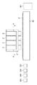
図2は記録ヘッドとインクタンクとが一体となったインクジェットカートリッジCの斜視図である。
【0040】
カートリッジCは、図2に示されているように、上方にインクタンクT、下方に記録ヘッド86を有しており、さらに、インクタンクTの上部には空気孔84が、インクタンクTと並ぶ位置にはヘッド側コネクタ85が設けられている。コネクタ85は記録ヘッド86を駆動するための信号などを受信すると共にインク残量検知信号を出力する。記録ヘッド86には、図中下方の底面側に開口する複数の吐出口を有する吐出口面1が形成されており、各吐出口に連通する液路部分にはインクを吐出するために必要とされる熱エネルギーを発生する電気熱変換体が配置されている。
【0041】
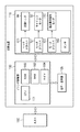
図3は、以上のように構成された記録装置の制御構成を説明するためのブロック図である。
【0042】
図3から分かるように、記録装置は装置各部の制御を行うプリンタ制御部100と、記録装置に対して種々の指示を行ったり記録装置の動作状況を表示する各種入力キーとLEDやLCDを備えた操作表示部105と、装置各部の機構を駆動する駆動部110とから構成されている。
【0043】
プリンタ制御部100は、CPU101、ROM102、RAM103、時間を計測するためのタイマ104などから構成されており、CPU101がROM102に格納されたプログラムを実行することにより装置各部の制御を行う。プリンタ制御部100には記録データや制御信号を供給するホスト150との通信を行うためのインタフェース(不図示)が備えられている。
【0044】
駆動部110には、プリンタ制御部100からの転送される記録データに基づいて記録ヘッド86の各電気熱変換体を駆動するためのヘッドドライバ120、プリンタ制御部100からの信号に基づいてキャリッジ2を主走査方向に移動させるべく、キャリッジモータ52を駆動するためのモータドライバ121、プリンタ制御部100からの信号に基づいて給紙ローラおよび紙送りローラを駆動して、記録媒体Pを副走査方向に搬送すべく、搬送モータ(兼回復系モータ)130を駆動するためのモータドライバ122が備えられている。
【0045】
これらによって記録媒体P上への記録動作が実行される。
【0046】
また、駆動部110には、記録媒体Pの有無を検出するためのセンサや、キャリッジ2のホームポジションに移動したことを検出するホームポジションセンサなどを含む各種センサ140を備え、これらの検出信号に基づいて、CPU101はキャリッジ2の位置や記録媒体Pの有無などを認識する。
【0047】
なお、搬送モータ130は駆動伝達ギア(不図示)を切り替えることにより、記録ヘッド86の吐出状態を維持・回復するための回復処理を行う回復ユニットを駆動することができる。
【0048】
次に予備吐出動作について説明する。
【0049】
図4は記録装置を前面から視たときの要部の概略図である。
【0050】
図4において、60は記録媒体Pに平坦な記録面を形成するためのプラテンであり、その上面において記録媒体Pが搬送される。そして、矢印aおよびb方向に記録ヘッドを搭載したキャリッジ2を移動させながら、記録媒体P上にインクを吐出して画像を記録していく。つまり、キャリッジ2が図4に示す矢印a、b方向のいずれの方向走査においても記録可能(往復記録)となっている。記録媒体Pに対する記録領域から左側に外れたホームポジション側にはキャップ300が備えられ、また記録領域から右側に外れた位置には予備吐出受け部401が備えられている。
【0051】
そして、記録動作中に所定の時間間隔で、キャップ300または予備吐出受け部401のいずれかの位置にキャリッジ2を移動させて、予備吐出を行うようにしている。
【0052】
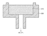
なお、キャップ300の内部に予備吐出する場合には、図5のキャップ300の断面図が示すように、キャップ300の内部にインク吸収体310を設けることがインクの漏れや跳ね返りを防止する上において好ましい。
【0053】
この実施形態では、予めキャップ300の形状と容積によって決定されるキャップ300のインク受容量に基づいて、キャップ300に予備吐出できるインク滴の最大吐出数つまり最大ドット数(X2)に基づいて、X2より小さいドット数(X1)を決定しておく。言い換えると、この実施形態では、キャップ300のインク容量に関して、2段階の閾値をもつことになる。
【0054】
最大ドット数(X2)の設計値は、これを容積に換算した場合、キャップ300の最大容積を下回るだけでなく、記録ヘッド温度の上昇による吐出量増加や記録ヘッドの吐出口からの蒸発防止のために行うキャップ上下動によるキャップ300の移動などによりインクが溢れ出すなどの弊害がないようにしなければならない。
【0055】
図5に示すようにキャップ300内部にはインク吸収体310を設けることがインクの漏れや跳ね返りを防止する上において好ましく、この場合はインク吸収体310の体積をも考慮して最大ドット数(X2)を決定しなければならない。また、最大ドット数(X2)は、記録装置に備えられた記録モードのなかでも最も時間の要する記録モードを選択した場合に所定の時間間隔でキャップ300内に予備吐出されるドット数より大きい方が好ましい。最も時間の要する記録モードは一般的に特殊な記録媒体に写真画像などを出力するために使用されるため、出力画像の画質は高画質であることが望まれる。この理由から、最も時間の要する記録モードでの記録には記録ヘッドを常に良好な状態に保つことが必要であり、このために予備吐出を行う必要があるからである。
【0056】
もしも、最大ドット数(X2)が最も時間の要する記録モード時にキャップ300に予備吐出されるドット数より小さいと、記録ヘッドの吐出口からのインク中の水分蒸発などにより、インク吐出位置が乱れたり、不吐出になったりして出力画像の画質の低下を招く恐れがある。そこで、上記の条件を満たした最大ドット数(X2)を設定することで、予期できないユーザよる記録中断命令時などにも所定の時間間隔でなされるキャップ300へのインク吐出が最大ドット数(X2)を超えた場合は、予備吐出を禁止してキャップ300から溢れ出して記録装置本体内部を汚染することを防止している。
【0057】
これに対して、最大ドット数(X2)より小さいドット数(X1)(この実施形態では最小ドット数という)は、記録装置に備えられた高速記録モードを選択した場合に、所定の時間間隔でキャップ300内に予備吐出されるドット数より大きい方が好ましい。これは、キャップ300からインクを排出するために行う動作(空吸引)が、最小ドット数(X1)を超えた場合に必要となるためである。つまり、最小ドット数(X1)が小さすぎると、記録毎にキャップ300からインクを排出する空吸引動作が実行されるため、記録装置のスループットの低下につながるからである。
【0058】
なお、キャップ300へ吐出されるインク液滴のドット数を表す指標は、記録ヘッド86の駆動条件などが決まっていればインク体積(容積)でもよく、予備吐出時におけるインクのドット数(N)をカウントすることにより、キャップ300に吐出されたインク総容量を知ることが出来る。また、1回の予備吐出によるドット数が決定していれば予備吐出の回数をカウントしてもよい。或いは、タイマを用いて所定の時間間隔で定期的に予備吐出を実行するのであれば、時間経過によりキャップ300内のインク総容量を知ることも出来る。
【0059】
次に、この実施形態に従う予備吐出制御の流れを説明する。
【0060】
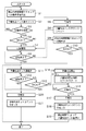
図6は予備吐出制御処理を示すフローチャートである。この図では記録装置がまず待機中にあるとして説明している。
【0061】
待機中の状態のとき、既に予備吐出がキャップ300に対してなされていればキャップへの予備吐出のドット数のカウント(N)には予備吐出された分がカウントされているし、予備吐出がされていない場合には、そのカウント値はゼロである。このドット数カウントは、ハードウエアでもソフトウエアでも実現することができ、いずれの計数方法を用いてもよい。
【0062】
まず、ステップS1ではホストから記録データ信号の受信待機中でも所定の時間間隔でキャップ300に予備吐出を行い、ステップS2ではその予備吐出されたドット数を予備吐出ドットカウント値(N)に加算する。
【0063】
次にステップS3で記録信号をホストから受信したかどうかを調べ、受信がなければ処理はステップS1に戻り、受信があると処理はステップS4に進み、記録媒体(例えば、記録用紙)を記録装置に給紙する前に、予備吐出カウント値(N)と最小ドット数(X1)と比較する。ここで、N≧X1であれば、処理はステップS5に進み、キャップ内からインクを排出する空吸引を実行し、さらにステップS6では予備吐出ドットカウント値(N)をゼロにリセットする。その後、処理はステップS7に進む。
【0064】
これに対して、N<X1であれば、処理はステップS7に進み、記録を開始する。次にステップS8では、記録が完了したかどうかを調べる。ここで、記録完了と判断された場合は、処理を終了する。これに対して、記録がまだ続行中であると判断された場合、処理はステップS9に進み、記録動作中でも所定の時間間隔でキャップ300へ予備吐出を行う。続く、ステップS10では予備吐出カウント値(N)と最小ドット数(X1)と比較する。ここで、N<X1であれば処理はステップS8に戻るが、N≧X1であれば処理はステップS11に進み、記録動作中の予備吐出における吐出ドット数を減少させる。なお、ステップS11の処理では、吐出ドット数を減少させる代わりに予備吐出の所定の時間間隔を長くしても良い、吐出ドット数を減少させると同時に予備吐出の所定の時間間隔を長くしても良い。
【0065】
ステップS11の後、処理はステップS12において、ステップS8と同様に記録完了かどうかを調べる。ここで、記録完了と判断された場合、処理はステップS20に進みキャップの空吸引を実行し、さらに、ステップS21では予備吐出ドットカウント値(N)をリセットし、処理を終了する。これに対して、記録がまだ続行中であると判断された場合、処理はステップS13に進む。
【0066】
ステップS13では予備吐出ドットカウント値(N)が上述したようにキャップ300の容積及び形状によって決定される最大ドット数(N2)より小さいかどうかを調べる。ここで、N<X2であれば処理はステップS12に戻るが、N≧X2であれば処理はステップS14に進み、キャップ300からインクが溢れることを防止するため、キャップ300へのインク吐出を禁止する。
【0067】
さらに、ステップS15では、ステップS14においてキャップ300へのインク吐出が禁止された時間を始点にして予備吐出禁止時間(T)を計測を開始する。そして、ステップS16では記録完了を待ち合わせ、記録完了と判断されると予備吐出禁止時間(T)の計測を終了して処理はステップS17に進む。このようにして記録完了までの予備吐出禁止時間(T)が測定される。ステップS17では記録媒体(紙)を排紙後、空吸引を実行してキャップ300内のインクを排出し、ステップS18では予備吐出ドットカウント値(N)をリセットする。
【0068】
最後にステップS19では、測定された予備吐出禁止時間(T)に応じて、次の記録動作の前に実行される所定間隔での予備吐出による吐出ドット数を増加させるよう記録装置に必要な設定を行う。
【0069】
なお、ステップS19の処理は、測定された予備吐出禁止時間(T)に応じて、待機中になされる予備吐出の時間間隔を短くするように設定しても良いし、或いは、図7に示したような予備吐出禁止時間(T)と予備吐出の時間間隔と吐出ドット数との関係を示すテーブルを予め用意しておき、測定された予備吐出禁止時間(T)に応じてこのテーブルを参照し、次に行う予備吐出までの時間間隔と吐出ドット数を決定してもよい。図7によれば、予備吐出禁止時間(T)が40秒(sec)であれば、次回予備吐出を実行するときに吐出ドット数は200ドット、時間間隔が0.5秒となるように選択される。
【0070】
その後、処理は終了し、次の記録信号の受信に備える。
【0071】
従って以上説明した実施形態に従えば、2つの異なる閾値を準備しておき、その内の小さい閾値を用いて記録を開始する際には記録待機中の予備吐出で消費されたインク量に従って空吸引の実行を制御し、記録動作中の予備吐出で消費されたインク量に従って予備吐出の際の吐出ドット数を変化させるように制御し、さらには大きい方の閾値を用いて記録動作中の予備吐出で消費されたインク量に従って予備吐出を禁止するよう制御するので、記録待ちの状況や記録動作の進行状況に合わせてキャップから吐出インクが溢れないように、柔軟にかつ最適な予備吐出を行わせることができる。
【0072】
これにより、記録装置内が溢れたインクで汚染されることが防止され、予備吐出に伴うインク消費と記録ヘッドを最適な状態に維持することの間でよい平衡が保たれ、予備吐出に伴うインク消費量を抑えるとともに、記録ヘッドを最適な状態に維持することができる。これにより、記録画像品質を良好に維持することができる。
【0073】
加えて、予備吐出を禁止した後に記録が完了すると空吸引を行ってキャップ300に溜まったインクを排出し、その後に再び行うようになる所定時間間隔での予備吐出の際の吐出ドット数を予備吐出禁止時間に従って変化させるように制御するので、予備吐出に伴うインク消費量と記録ヘッドを良好な状態に維持することの間で最適なバランスを維持した柔軟かつ最適な予備吐出を行わせることができる。
【0074】
以上の実施形態において、記録ヘッドから吐出される液滴はインクであるとして説明し、さらにインクタンクに収容される液体はインクであるとして説明したが、その収容物はインクに限定されるものではない。例えば、記録画像の定着性や耐水性を高めたり、その画像品質を高めたりするために記録媒体に対して吐出される処理液のようなものがインクタンクに収容されていても良い。
【0075】
そして以上の実施形態は、特にインクジェット記録方式の中でも、インク吐出を行わせるために利用されるエネルギーとして熱エネルギーを発生する手段(例えば電気熱変換体やレーザ光等)を備え、前記熱エネルギーによりインクの状態変化を生起させる方式を用いることにより記録の高密度化、高精細化が達成できる。
【0076】
その代表的な構成や原理については、例えば、米国特許第4723129号明細書、同第4740796号明細書に開示されている基本的な原理を用いて行うものが好ましい。この方式はいわゆるオンデマンド型、コンティニュアス型のいずれにも適用可能であるが、特に、オンデマンド型の場合には、液体(インク)が保持されているシートや液路に対応して配置されている電気熱変換体に、記録情報に対応していて核沸騰を越える急速な温度上昇を与える少なくとも1つの駆動信号を印加することによって、電気熱変換体に熱エネルギーを発生せしめ、記録ヘッドの熱作用面に膜沸騰を生じさせて、結果的にこの駆動信号に1対1で対応した液体(インク)内の気泡を形成できるので有効である。この気泡の成長、収縮により吐出用開口を介して液体(インク)を吐出させて、少なくとも1つの滴を形成する。この駆動信号をパルス形状にすると、即時適切に気泡の成長収縮が行われるので、特に応答性に優れた液体(インク)の吐出が達成でき、より好ましい。
【0077】
このパルス形状の駆動信号としては、米国特許第4463359号明細書、同第4345262号明細書に記載されているようなものが適している。なお、上記熱作用面の温度上昇率に関する発明の米国特許第4313124号明細書に記載されている条件を採用すると、さらに優れた記録を行うことができる。
【0078】
記録ヘッドの構成としては、上述の各明細書に開示されているような吐出口、液路、電気熱変換体の組み合わせ構成(直線状液流路または直角液流路)の他に熱作用面が屈曲する領域に配置されている構成を開示する米国特許第4558333号明細書、米国特許第4459600号明細書を用いた構成も本発明に含まれるものである。加えて、複数の電気熱変換体に対して、共通するスロットを電気熱変換体の吐出部とする構成を開示する特開昭59−123670号公報や熱エネルギーの圧力波を吸収する開口を吐出部に対応させる構成を開示する特開昭59−138461号公報に基づいた構成としても良い。
【0079】
さらに、記録装置が記録できる最大記録媒体の幅に対応した長さを有するフルラインタイプの記録ヘッドとしては、上述した明細書に開示されているような複数記録ヘッドの組み合わせによってその長さを満たす構成や、一体的に形成された1個の記録ヘッドとしての構成のいずれでもよい。
【0080】
加えて、上記の実施形態で説明した記録ヘッド自体に一体的にインクタンクが設けられたカートリッジタイプの記録ヘッドのみならず、装置本体に装着されることで、装置本体との電気的な接続や装置本体からのインクの供給が可能になる交換自在のチップタイプの記録ヘッドを用いてもよい。
【0081】
また、以上説明した記録装置の構成に、記録ヘッドに対する回復手段、予備的な手段等を付加することは記録動作を一層安定にできるので好ましいものである。これらを具体的に挙げれば、記録ヘッドに対してのキャッピング手段、クリーニング手段、加圧あるいは吸引手段、電気熱変換体あるいはこれとは別の加熱素子あるいはこれらの組み合わせによる予備加熱手段などがある。また、記録とは別の吐出を行う予備吐出モードを備えることも安定した記録を行うために有効である。
【0082】
さらに、記録装置の記録モードとしては黒色等の主流色のみの記録モードだけではなく、記録ヘッドを一体的に構成するか複数個の組み合わせによってでも良いが、異なる色の複色カラー、または混色によるフルカラーの少なくとも1つを備えた装置とすることもできる。
【0083】
以上説明した実施の形態においては、インクが液体であることを前提として説明しているが、室温やそれ以下で固化するインクであっても、室温で軟化もしくは液化するものを用いても良く、あるいはインクジェット方式ではインク自体を30°C以上70°C以下の範囲内で温度調整を行ってインクの粘性を安定吐出範囲にあるように温度制御するものが一般的であるから、使用記録信号付与時にインクが液状をなすものであればよい。
【0084】
加えて、積極的に熱エネルギーによる昇温をインクの固形状態から液体状態への状態変化のエネルギーとして使用せしめることで積極的に防止するため、またはインクの蒸発を防止するため、放置状態で固化し加熱によって液化するインクを用いても良い。いずれにしても熱エネルギーの記録信号に応じた付与によってインクが液化し、液状インクが吐出されるものや、記録媒体に到達する時点では既に固化し始めるもの等のような、熱エネルギーの付与によって初めて液化する性質のインクを使用する場合も本発明は適用可能である。このような場合インクは、特開昭54−56847号公報あるいは特開昭60−71260号公報に記載されるような、多孔質シート凹部または貫通孔に液状または固形物として保持された状態で、電気熱変換体に対して対向するような形態としてもよい。本発明においては、上述した各インクに対して最も有効なものは、上述した膜沸騰方式を実行するものである。
【0085】
さらに加えて、本発明に係る記録装置の形態としては、コンピュータ等の情報処理機器の画像出力端末として一体または別体に設けられるものの他、リーダ等と組み合わせた複写装置、さらには送受信機能を有するファクシミリ装置の形態を取るものであっても良い。
【0086】
なお、本発明は、複数の機器(例えばホストコンピュータ、インタフェース機器、リーダ、プリンタなど)から構成されるシステムに適用しても、一つの機器からなる装置(例えば、複写機、ファクシミリ装置など)に適用してもよい。
【0087】
また、本発明の目的は、前述した実施形態の機能を実現するソフトウェアのプログラムコードを記録した記憶媒体(または記録媒体)を、システムあるいは装置に供給し、そのシステムあるいは装置のコンピュータ(またはCPUやMPU)が記憶媒体に格納されたプログラムコードを読み出し実行することによっても、達成されることは言うまでもない。この場合、記憶媒体から読み出されたプログラムコード自体が前述した実施形態の機能を実現することになり、そのプログラムコードを記憶した記憶媒体は本発明を構成することになる。また、コンピュータが読み出したプログラムコードを実行することにより、前述した実施形態の機能が実現されるだけでなく、そのプログラムコードの指示に基づき、コンピュータ上で稼働しているオペレーティングシステム(OS)などが実際の処理の一部または全部を行い、その処理によって前述した実施形態の機能が実現される場合も含まれることは言うまでもない。
【0088】
さらに、記憶媒体から読み出されたプログラムコードが、コンピュータに挿入された機能拡張カードやコンピュータに接続された機能拡張ユニットに備わるメモリに書込まれた後、そのプログラムコードの指示に基づき、その機能拡張カードや機能拡張ユニットに備わるCPUなどが実際の処理の一部または全部を行い、その処理によって前述した実施形態の機能が実現される場合も含まれることは言うまでもない。
【0089】
【発明の効果】
以上説明したように本発明によれば、記録状況に合わせて柔軟に対応して予備吐出を効率良く行うとともに、キャップから予備吐出によって溜まったインクが溢れることがなくなり、記録装置内をインクで汚染されることを防止できるという効果がある。
【図面の簡単な説明】
【図1】本発明の代表的な実施形態であるインクジェット方式に従って記録を行う記録ヘッドを備えた記録装置の槻略構成を示す斜視図である。
【図2】図1に示した記録装置で用いられるインクジェットカートリッジの斜視図である。
【図3】図1に示した記録装置の制御回路の構成を示すブロック図である。
【図4】図1に示した記録装置における予備吐出受け部の位置関係および予備吐出動作の説明図である。
【図5】図4に示したキャップの拡大断面図である。
【図6】予備吐出制御処理を説明するためのフローチャートである。
【図7】予備吐出禁止時間に応じて次に実行される予備吐出における吐出ドット数と実行時間間隔とを選択するテーブルを示す図である。
【符号の説明】
2 キャリッジ
86 記録ヘッド
100 プリンタ制御部
300 キャップ
401 予備吐出受け部
C インクジェットカートリッジ
P 記録媒体[0001]
BACKGROUND OF THE INVENTION
The present invention relates to a recording apparatus and a preliminary discharge control method, and more particularly to a recording apparatus and a preliminary discharge control method for performing recording using an ink jet recording head.
[0002]
[Prior art]
The ink jet recording system is used in various printers, copiers, facsimiles, and the like for reasons such as low noise, low running cost, apparatus miniaturization, and easy colorization of recorded images.
[0003]
A recording apparatus adopting this method records an image on a recording medium such as paper, cloth, non-woven fabric, or OHP film by ejecting minute ink droplets from a minute ejection port of an ink jet recording head (hereinafter referred to as recording head). To do. Therefore, when the recording operation is not performed and the recording head has not ejected ink for a long time, the ink in the ink ejection port (hereinafter referred to as ejection port) is evaporated and dried, resulting in a viscosity. Increased ink or solidified ink may become clogged in the discharge port and cause a twist (a phenomenon in which the ink discharge direction changes) or a discharge failure. Therefore, the ink jet recording apparatus is provided with a recovery means for performing a recovery process for recovering the ink ejection state in order to eliminate such inconvenience.
[0004]
An ink jet recording apparatus (hereinafter referred to as a recording apparatus) employs the following configuration in order to eliminate twist and ink non-ejection caused by evaporation and drying of ink in the ejection port.
[0005]
First, when the recording operation is not performed, the ejection port surface where the ejection port of the recording head is formed is covered with a cap to prevent the ink in the ejection port from being evaporated and dried. In the unlikely event that the ink viscosity increases and sticks to the discharge port to cause a discharge failure, or foreign matter adheres to the surface of the discharge port, the suction pump connected to the inside of the cap increases the viscosity in the discharge port. The discharged ink and the foreign matter on the discharge port surface are sucked and discharged together with the ink, thereby recovering the normal discharge state (this is called suction recovery).
[0006]
Also, in the recording operation of a recording apparatus adopting an on-demand type ink jet recording method, not all of the plurality of ejection openings provided in one recording head are always used for recording, and are not used for a certain period of time. There is an unused nozzle. Further, in the case of a configuration provided with a plurality of recording heads corresponding to each color ink as in a color recording apparatus, the entire recording head in which recording data is not transferred may not be used.
[0007]
Furthermore, in a so-called serial scan method in which recording is performed by scanning a carriage mounted with a recording head, the carriage is continuously scanned for a long time or stopped while the ejection port surface of the unused recording head is not capped. In this case, the ink in the ejection port where ink ejection does not occur is evaporated and dried, resulting in a decrease in ink ejection performance. This causes a reduction in the quality of the recorded image.
[0008]
In order to prevent such a phenomenon, the recording apparatus generally discharges ink at a predetermined place at a certain time interval regardless of recording data, and discharges ink in the nozzle to replace it with fresh ink. By doing this, the ink ejection state is always kept appropriate. Such an ink ejection operation is called “preliminary ejection”.
[0009]
The ink ejected by this preliminary ejection is ejected in the cap of the recovery unit or to a place called a preparatory ejection position provided separately so that the recording medium and the recording apparatus are not scattered and contaminated. In other words, it is stored in a waste ink tank. Techniques for ejecting ink into the cap are described in, for example, Japanese Patent Application Laid-Open Nos. 59-7053 and 4-52219.
[0010]
Recently, in order to improve the quality of a recorded image, a recording performance improving liquid (hereinafter referred to as a processing liquid) for improving the quality of the recorded image is ejected onto the recording medium in addition to the recording ink. There has also been proposed a technique for performing recording while insolubilizing ink on a medium to improve water resistance and preventing bleeding. In a recording apparatus employing such a technique, the receiving portions that receive the ink and the processing liquid at the time of preliminary ejection are separated from each other so that the recording head and the processing liquid do not mix in the recording apparatus. A plurality of them are provided. However, providing a plurality of receiving portions for receiving ink or processing liquid for preliminary ejection leads to an increase in the size of the apparatus. In order to reduce the size of the recording apparatus, it has been proposed to use the inside of the cap as a preliminary discharge position.
[0011]
Recently, it has been required to record an image on a long recording paper (banner paper) such as a banner. When recording on such a long recording sheet, the number of preliminary ejections during the recording operation is also smaller than when recording on a standard size (A4, legal size, etc.) paper such as copy paper. Therefore, the amount of ink used for preliminary ejection also increases. In the case of a configuration in which preliminary ejection is performed in the cap, the ink accumulated in the cap must be removed by suction (hereinafter referred to as “empty suction”) with a suction pump connected to the inside of the cap. If the operation enters the middle of the recording operation, the throughput is reduced.
[0012]
In order to solve this problem, Japanese Patent Application Laid-Open No. 3-234638 discloses that ink remaining in the cap is idled when recording for one page is completed while performing preliminary ejection in the cap. is suggesting.
[0013]
Further, in the case of a serial type recording apparatus that reciprocally scans a carriage on which a recording head is mounted in a direction perpendicular to the conveyance direction of a recording medium such as paper, a drive source (such as a motor) for mainly driving the carriage A drive source for transporting the recording medium and a drive source for driving recovery means for performing recovery processing for recovering the ejection state of the recording head, and driving these drive sources as necessary In recent years, the drive source for transporting the recording medium and the drive source for the recovery means have been made common in order to reduce the size and cost of the recording apparatus. There are many devices that employ a configuration that switches between and uses. For example, Japanese Patent Application Laid-Open No. 1-82962 discloses a recording apparatus in which a drive motor for a suction pump for recovery processing of a recording head and a paper feed motor for feeding a recording medium are used.
[0014]
[Problems to be solved by the invention]
However, in the case where the conveyance control and the recovery control are driven by the same motor as in the conventional example, the following problems may occur.
[0015]
For example, when an attempt is made to execute a recovery process when a recording medium (for example, a recording sheet) is set in the recording apparatus, the same motor is used, so that the recovery process is performed. The recording paper is conveyed. For this reason, the position of the recording paper is shifted, and the recorded image is not connected properly. In some cases, the recording paper in the middle of recording may be detached from the transport mechanism. In order to solve these problems, it is necessary to perform control so that the recovery operation is not performed or not performed during the recording operation or while the recording paper is in the transport mechanism.
[0016]
In addition, when recording on a long recording sheet as described above with such a recording apparatus, the amount of preliminary ejection ink increases, and the idle suction operation cannot be performed during the recording operation. For this reason, if preliminary ejection is performed, ink may overflow from the cap and contaminate the inside of the recording apparatus. In order to solve this problem, Japanese Patent Application Laid-Open No. 10-278299 discloses a preliminary ejection control means for prohibiting preliminary ejection to the cap when the amount of ink in the cap exceeds a predetermined amount. However, when preliminary ejection to the cap is prohibited, it is inevitable that a discharge port that is unused for a long time is generated, resulting in a decrease in ink ejection performance and a decrease in recorded image quality. End up. Further, such a quality deterioration may affect not only the image currently being recorded but also the next image to be recorded.
[0017]
The present invention has been made in view of the above-described conventional example, and can efficiently perform preliminary ejection for ejecting ink that does not contribute to image recording from a recording head, and reduce contamination inside the recording apparatus and preliminary ejection. It aims to provide a control method.
[0018]
[Means for Solving the Problems]
In order to achieve the above object, the recording apparatus of the present invention has the following configuration.
[0019]
That is, it covers the discharge port surface where the discharge port of the ink jet recording head is formed and receives ink discharged from the discharge port. Do Cap and said cap From Empty suction means for discharging ink, and the cap in the cap Discharge port Preliminary ejection means for preliminarily ejecting ink from the ink, and the preliminary ejection Was ink Number of dots The count Do count Means and said count By means count Was Dot number and preset The first threshold and The The first comparison means to compare and the comparison result by the first comparison means Depending on, Discharge in subsequent preliminary discharge Number of dots The first preliminary discharge control means for controlling so as to decrease the discharge, and the first preliminary discharge control means The number of dots Decrease After letting Said count By means count Was The number of dots and the preset A second threshold value greater than the first threshold value; The The comparison result by the second comparison means to be compared with the second comparison means Depending on, Preliminary ejection prohibiting means for controlling the preliminary ejection operation to be prohibited, and at the time when the preliminary ejection operation is prohibited by the preliminary ejection prohibiting means after the recording operation is completed. Depending on In subsequent preliminary discharge Increase the number of ejected dots And a second preliminary discharge control unit that controls the recording apparatus.
[0020]
Furthermore, after the recording operation is completed, it includes an idle suction control means for controlling the idle suction means to drive the idle suction operation, and the idle suction control means further includes the first comparison means prior to the start of the recording operation. It is desirable to control the idle suction means to perform the idle suction operation in accordance with the result of the comparison.
[0021]
In addition, a first recording mode for performing high-speed recording as a recording operation and a second recording mode for performing high-quality recording that requires time are provided, and the first threshold is recorded in the first recording mode. In this case, the second threshold value is determined based on the ink consumption amount consumed in the preliminary ejection, and the second threshold value is the ink consumption amount consumed in the preliminary ejection when the recording is performed in the second recording mode and the ink receiving amount of the cap. It should be determined based on Further, if the ink absorber is accommodated in the cap, the second threshold value is preferably determined in consideration of the volume of the ink absorber.
[0022]
Further, ink is discharged by the empty suction means. When, By the counting means Number of dots May be configured to be reset.
[0023]
In the preliminary discharge by the first and second preliminary discharge control means Number of ejection dots Increase or decrease Per time Increase / decrease in the number of ejection dots and / or preliminary ejection of It is desirable to be done by changing the operation interval.
[0024]
Further, the second preliminary ejection control means includes a measuring means for measuring a time from the prohibition of the preliminary ejection operation to the end of the recording operation, and a table referred to for determining the ink consumption amount in the resumed preliminary ejection. It is good to prepare.
[0025]
Furthermore, the ink jet recording head preferably includes an electrothermal transducer for generating thermal energy to be applied to the ink in order to eject the ink using thermal energy.
[0026]
According to another aspect of the invention, the discharge port surface of the inkjet recording head on which the discharge port is formed is covered and ink discharged from the discharge port is received. Do With cap , In the cap Discharge port Preliminary ejection means for preliminary ejection of ink from , The cap From A preliminary discharge control method for use in a recording apparatus including an empty suction unit for discharging ink, the preliminary discharge Was ink Number of dots The count Do count Process, and count In the process count Was Dot number and preset The first threshold and The Comparison results in the first comparison step to be compared and the first comparison step Depending on, Discharge in subsequent preliminary discharge Number of dots A first preliminary discharge control step for controlling so as to reduce, In the first preliminary discharge control process vomit The number of dots Decrease After letting Said count In the process count Was The number of dots and the preset A second threshold value greater than the first threshold value; The The comparison result by the second comparison step to be compared and the second comparison means Depending on, A preliminary ejection prohibiting step for controlling the preliminary ejection operation to be prohibited; and In the preliminary discharge prohibition process During the time when preliminary discharge operation was prohibited Depending on In subsequent preliminary discharge Increase the number of ejected dots And a second preliminary discharge control step that controls the preliminary discharge control method.
[0028]
With the above-described configuration, the present invention enables inkjet recording to the inside of a cap at a predetermined time interval separately from a recording operation and a cap that covers the inkjet recording head and its ink ejection port surface and can accept ink ejected from the ejection port. In a recording apparatus provided with means for preliminarily ejecting ink from the head, the ink consumption by the preliminary ejection is accumulated, and the accumulated ink consumption for each preliminary ejection is compared with the first threshold value, and the comparison is made. In accordance with the result, control is performed so as to decrease the ink discharge amount in the subsequent preliminary discharge, and the accumulated ink consumption amount is compared with the second threshold value that is larger than the first threshold value every time the preliminary discharge is reduced. In accordance with the comparison result, control is performed so that the preliminary discharge operation is prohibited, and after the recording operation is completed, the preliminary discharge operation is prohibited. It restarts the preliminary ejection after the Te is controlled to increase the amount of ink consumption at the preliminary ejection.
[0029]
DETAILED DESCRIPTION OF THE INVENTION
Preferred embodiments of the present invention will be described below in detail with reference to the accompanying drawings.
[0030]
FIG. 1 is a perspective view showing a schematic configuration of a recording apparatus including a recording head that performs recording in accordance with an ink jet method according to a representative embodiment of the present invention.
[0031]
In FIG. 1, C is an ink jet cartridge (hereinafter referred to as a cartridge) having an ink tank above it and a recording head below it, and further provided with a connector for receiving a signal for driving the recording head. A carriage for mounting a plurality of cartridges C. The ink tanks of the plurality of cartridges C store different color inks such as yellow, magenta, cyan, and black inks. In addition, the
[0032]
11 is a scanning rail that extends in the scanning direction of the recording head (main scanning direction) and slidably supports the
[0033]
The recording head provided in the cartridge C mounted on the
[0034]
In the recording apparatus of this embodiment, a recovery system unit is disposed on the home position side on the left side of FIG.
[0035]
In FIG. 1, regarding this recovery system unit,
[0036]
Further, the inside of the
[0037]
[0038]
In the recording apparatus of this embodiment, the conveyance drive motor for conveying the recording medium P and the drive motor for operating the recovery system unit are made common and common.
[0039]
FIG. 2 is a perspective view of an ink jet cartridge C in which a recording head and an ink tank are integrated.
[0040]
As shown in FIG. 2, the cartridge C has an ink tank T on the upper side and a
[0041]
FIG. 3 is a block diagram for explaining the control configuration of the recording apparatus configured as described above.
[0042]
As can be seen from FIG. 3, the recording apparatus includes a
[0043]
The
[0044]
The driving
[0045]
Thus, the recording operation on the recording medium P is executed.
[0046]
The
[0047]
The
[0048]
Next, the preliminary discharge operation will be described.
[0049]
FIG. 4 is a schematic view of the main part when the recording apparatus is viewed from the front.
[0050]
In FIG. 4,
[0051]
Then, the
[0052]
In the case of preliminary ejection inside the
[0053]
In this embodiment, based on the ink receiving amount of the
[0054]
The design value of the maximum number of dots (X2), when converted into a volume, is not only less than the maximum volume of the
[0055]
As shown in FIG. 5, it is preferable to provide an
[0056]
If the maximum number of dots (X2) is smaller than the number of dots preliminarily ejected to the
[0057]
On the other hand, the number of dots (X1) (referred to as the minimum number of dots in this embodiment) smaller than the maximum number of dots (X2) is determined at a predetermined time interval when the high-speed recording mode provided in the recording apparatus is selected. It is preferable that the number of dots preliminarily ejected into the
[0058]
The index representing the number of dots of ink droplets ejected to the
[0059]
Next, the flow of the preliminary discharge control according to this embodiment will be described.
[0060]
FIG. 6 is a flowchart showing the preliminary discharge control process. In this figure, it is assumed that the recording apparatus is in standby.
[0061]
In the standby state, if preliminary ejection has already been performed on the
[0062]
First, in step S1, preliminary ejection is performed to the
[0063]
Next, in step S3, it is checked whether or not a recording signal has been received from the host. If there is no reception, the process returns to step S1, and if there is a reception, the process proceeds to step S4. Before the sheet is fed, the preliminary ejection count value (N) is compared with the minimum dot number (X1). Here, if N ≧ X1, the process proceeds to step S5 to execute idle suction for discharging ink from the cap, and further, in step S6, the preliminary ejection dot count value (N) is reset to zero. Thereafter, the process proceeds to step S7.
[0064]
On the other hand, if N <X1, the process proceeds to step S7 to start recording. Next, in step S8, it is checked whether the recording is completed. Here, when it is determined that the recording is completed, the processing is terminated. On the other hand, if it is determined that printing is still in progress, the process proceeds to step S9, and preliminary ejection is performed to the
[0065]
After step S11, the process checks in step S12 whether the recording is completed as in step S8. If it is determined that the recording is completed, the process proceeds to step S20 to perform idle suction of the cap. In step S21, the preliminary ejection dot count value (N) is reset, and the process ends. On the other hand, if it is determined that the recording is still in progress, the process proceeds to step S13.
[0066]
In step S13, it is checked whether the preliminary ejection dot count value (N) is smaller than the maximum number of dots (N2) determined by the volume and shape of the
[0067]
Further, in step S15, measurement of the preliminary ejection inhibition time (T) is started from the time when ink ejection to the
[0068]
Finally, in step S19, the setting necessary for the printing apparatus to increase the number of ejection dots by the preliminary ejection at a predetermined interval executed before the next recording operation according to the measured preliminary ejection inhibition time (T). I do.
[0069]
Note that the process of step S19 may be set so as to shorten the time interval of the preliminary ejection performed during standby in accordance with the measured preliminary ejection inhibition time (T), or as shown in FIG. A table showing the relationship between the preliminary ejection inhibition time (T), the preliminary ejection time interval, and the number of ejection dots is prepared in advance, and this table is referred to according to the measured preliminary ejection inhibition time (T). Then, the time interval until the next preliminary ejection and the number of ejection dots may be determined. According to FIG. 7, if the preliminary ejection inhibition time (T) is 40 seconds (sec), the next preliminary ejection is executed so that the number of ejection dots is 200 dots and the time interval is 0.5 seconds. Is done.
[0070]
Thereafter, the process ends and prepares for reception of the next recording signal.
[0071]
Therefore, according to the embodiment described above, two different threshold values are prepared, and when the recording is started using a small threshold value among them, the idle suction is performed according to the ink amount consumed in the preliminary discharge during the recording standby. Control to change the number of ejection dots at the time of preliminary ejection according to the amount of ink consumed by preliminary ejection during the recording operation, and further using the larger threshold value to perform preliminary ejection during the recording operation Control is made so that preliminary ejection is prohibited according to the amount of ink consumed, so that the preliminary ejection can be performed flexibly and optimally so that the ejected ink does not overflow from the cap according to the recording standby status or the progress status of the recording operation. be able to.
[0072]
As a result, the inside of the recording apparatus is prevented from being contaminated with overflowing ink, and a good balance is maintained between ink consumption accompanying preliminary ejection and maintaining the recording head in an optimum state. It is possible to reduce consumption and maintain the recording head in an optimum state. Thereby, the recorded image quality can be maintained satisfactorily.
[0073]
In addition, when recording is completed after prohibiting preliminary ejection, idle suction is performed to discharge the ink accumulated in the
[0074]
In the above embodiment, the liquid droplets ejected from the recording head have been described as ink, and the liquid stored in the ink tank has been described as ink. However, the container is not limited to ink. Absent. For example, a treatment liquid discharged to the recording medium may be stored in the ink tank in order to improve the fixability and water resistance of the recorded image or to improve the image quality.
[0075]
The above embodiment includes means (for example, an electrothermal converter, a laser beam, etc.) for generating thermal energy as energy used for performing ink discharge, particularly in the ink jet recording system, and the thermal energy By using a system that causes a change in the state of the ink, it is possible to achieve higher recording density and higher definition.
[0076]
As its typical configuration and principle, for example, those performed using the basic principle disclosed in US Pat. Nos. 4,723,129 and 4,740,796 are preferable. This method can be applied to both the so-called on-demand type and continuous type. In particular, in the case of the on-demand type, it is arranged corresponding to the sheet or liquid path holding the liquid (ink). By applying at least one drive signal corresponding to the recorded information and giving a rapid temperature rise exceeding nucleate boiling to the electrothermal transducer, the thermal energy is generated in the electrothermal transducer, and the recording head This is effective because film boiling occurs on the heat acting surface of the liquid, and as a result, bubbles in the liquid (ink) corresponding to the drive signal on a one-to-one basis can be formed. By the growth and contraction of the bubbles, liquid (ink) is ejected through the ejection opening to form at least one droplet. When this drive signal is in a pulse shape, the bubble growth and contraction is performed immediately and appropriately, and thus it is possible to achieve the discharge of liquid (ink) having particularly excellent responsiveness.
[0077]
As this pulse-shaped drive signal, those described in US Pat. Nos. 4,463,359 and 4,345,262 are suitable. Further excellent recording can be performed by employing the conditions described in US Pat. No. 4,313,124 of the invention relating to the temperature rise rate of the heat acting surface.
[0078]
As the configuration of the recording head, in addition to the combination configuration (straight liquid flow path or right-angle liquid flow path) of the discharge port, the liquid path, and the electrothermal transducer as disclosed in each of the above-mentioned specifications, the heat acting surface The configurations using US Pat. No. 4,558,333 and US Pat. No. 4,459,600, which disclose a configuration in which is disposed in a bending region, are also included in the present invention. In addition, Japanese Patent Application Laid-Open No. 59-123670, which discloses a configuration in which a common slot is used as a discharge portion of an electrothermal transducer, or an opening that absorbs a pressure wave of thermal energy is discharged to a plurality of electrothermal transducers. A configuration based on Japanese Patent Laid-Open No. 59-138461 disclosing a configuration corresponding to each part may be adopted.
[0079]
Furthermore, as a full-line type recording head having a length corresponding to the width of the maximum recording medium that can be recorded by the recording apparatus, the length is satisfied by a combination of a plurality of recording heads as disclosed in the above specification. Either a configuration or a configuration as a single recording head formed integrally may be used.
[0080]
In addition to the cartridge-type recording head in which the ink tank is integrally provided in the recording head itself described in the above embodiment, it can be electrically connected to the apparatus body by being attached to the apparatus body. A replaceable chip type recording head that can supply ink from the apparatus main body may be used.
[0081]
In addition, it is preferable to add recovery means, preliminary means, and the like for the recording head to the configuration of the recording apparatus described above because the recording operation can be further stabilized. Specific examples thereof include a capping unit for the recording head, a cleaning unit, a pressurizing or sucking unit, an electrothermal converter, a heating element different from this, or a preheating unit using a combination thereof. In addition, it is effective to provide a preliminary ejection mode for performing ejection different from recording in order to perform stable recording.
[0082]
Further, the recording mode of the recording apparatus is not limited to the recording mode of only the mainstream color such as black, but the recording head may be integrated or may be a combination of a plurality of colors. An apparatus having at least one of full colors can also be provided.
[0083]
In the embodiment described above, the description is made on the assumption that the ink is a liquid, but it may be an ink that is solidified at room temperature or lower, or an ink that is softened or liquefied at room temperature, Alternatively, the ink jet method generally controls the temperature of the ink so that the viscosity of the ink is within a stable discharge range by adjusting the temperature within a range of 30 ° C. or higher and 70 ° C. or lower. It is sufficient if the ink sometimes forms a liquid.
[0084]
In addition, it is solidified in a stand-by state in order to actively prevent temperature rise by heat energy as energy for changing the state of ink from the solid state to the liquid state, or to prevent ink evaporation. Ink that is liquefied by heating may be used. In any case, by applying heat energy according to the application of thermal energy according to the recording signal, the ink is liquefied and liquid ink is ejected, or when it reaches the recording medium, it already starts to solidify. The present invention can also be applied to the case of using ink having the property of being liquefied for the first time. In such a case, the ink is held as a liquid or solid in a porous sheet recess or through-hole as described in JP-A-54-56847 or JP-A-60-71260, It is good also as a form which opposes with respect to an electrothermal converter. In the present invention, the most effective one for each of the above-described inks is to execute the above-described film boiling method.
[0085]
In addition, as a form of the recording apparatus according to the present invention, a copying apparatus combined with a reader or the like, and a transmission / reception function are provided as an image output terminal of an information processing apparatus such as a computer or the like. It may take the form of a facsimile machine.
[0086]
Note that the present invention can be applied to a system (for example, a copier, a facsimile machine, etc.) consisting of a single device even when applied to a system composed of a plurality of devices (for example, a host computer, interface device, reader, printer, etc.). You may apply.
[0087]
Also, an object of the present invention is to supply a storage medium (or recording medium) that records a program code of software that realizes the functions of the above-described embodiments to a system or apparatus, and to perform computer (or CPU or CPU) of the system or apparatus. Needless to say, this can also be achieved when the MPU) reads and executes the program code stored in the storage medium. In this case, the program code itself read from the storage medium realizes the functions of the above-described embodiments, and the storage medium storing the program code constitutes the present invention. Further, by executing the program code read by the computer, not only the functions of the above-described embodiments are realized, but also an operating system (OS) running on the computer based on the instruction of the program code. It goes without saying that a case where the function of the above-described embodiment is realized by performing part or all of the actual processing and the processing is included.
[0088]
Furthermore, after the program code read from the storage medium is written into a memory provided in a function expansion card inserted into the computer or a function expansion unit connected to the computer, the function is based on the instruction of the program code. It goes without saying that the CPU or the like provided in the expansion card or the function expansion unit performs part or all of the actual processing and the functions of the above-described embodiments are realized by the processing.
[0089]
【The invention's effect】
As described above, according to the present invention, preliminary ejection can be efficiently performed flexibly in accordance with the recording situation, and ink accumulated by preliminary ejection can be prevented from overflowing from the cap, and the inside of the recording apparatus can be contaminated with ink. There is an effect that can be prevented.
[Brief description of the drawings]
FIG. 1 is a perspective view illustrating a schematic configuration of a recording apparatus including a recording head that performs recording in accordance with an ink jet method according to a representative embodiment of the present invention.
FIG. 2 is a perspective view of an ink jet cartridge used in the recording apparatus shown in FIG.
FIG. 3 is a block diagram illustrating a configuration of a control circuit of the recording apparatus illustrated in FIG. 1;
4 is an explanatory diagram of a positional relationship and a preliminary discharge operation of a preliminary discharge receiver in the recording apparatus illustrated in FIG.
FIG. 5 is an enlarged cross-sectional view of the cap shown in FIG.
FIG. 6 is a flowchart for explaining a preliminary ejection control process.
FIG. 7 is a diagram showing a table for selecting the number of ejection dots and the execution time interval in preliminary ejection to be executed next in accordance with the preliminary ejection inhibition time.
[Explanation of symbols]
2 Carriage
86 Recording head
100 Printer control unit
300 caps
401 Pre-discharge receiver
C Inkjet cartridge
P Recording medium
Claims (10)
前記キャップからインクを排出する空吸引手段と、
前記キャップ内に前記吐出口からインクを予備吐出させる予備吐出手段と、
前記予備吐出されたインクのドット数をカウントするカウント手段と、
前記カウント手段によってカウントされたドット数と予め設定された第1の閾値とを比較する第1比較手段と、
前記第1比較手段による比較結果に応じて、以降の予備吐出における吐出ドット数を減少させるように制御する第1予備吐出制御手段と、
前記第1予備吐出制御手段によって吐出ドット数を減少させた後に、前記カウント手段によってカウントされたドット数と予め設定された前記第1の閾値よりも大きい第2の閾値とを比較する第2比較手段と、
前記第2比較手段による比較結果に応じて、予備吐出の動作を禁止するように制御する予備吐出禁止手段と、
記録動作終了後に前記予備吐出禁止手段によって予備吐出の動作が禁止されていた時間に応じて以降の予備吐出における吐出ドット数を増加させるように制御する第2予備吐出制御手段とを有することを特徴とする記録装置。 A cap that covers the ejection port surface where the ejection port of the inkjet recording head is formed and receives ink ejected from the ejection port;
Empty suction means for discharging ink from the cap;
Preliminary ejection means for preliminarily ejecting ink from the ejection port into the cap;
Counting means for counting the number of dots the preliminary discharge ink,
First comparison means for comparing the number of dots counted by the counting means with a preset first threshold;
First preliminary ejection control means for controlling to reduce the number of ejection dots in the subsequent preliminary ejection according to the comparison result by the first comparison means;
After the number of ejection dots is decreased by the first preliminary ejection control means, a second comparison for comparing the number of dots counted by the counting means with a second threshold value greater than the preset first threshold value. Means,
Preliminary ejection prohibiting means for controlling to prohibit the preliminary ejection operation according to the comparison result by the second comparison means;
And a second preliminary discharge control unit that controls to increase the number of ejection dots in the subsequent preliminary discharge according to the time during which the preliminary discharge operation is prohibited by the preliminary discharge prohibiting unit after the recording operation is completed. A recording device.
前記第1の閾値は前記第1の記録モードで記録を行う場合の予備吐出において消費されるインク消費量に基づいて定められ、
前記第2の閾値は前記第2の記録モードで記録を行う場合の予備吐出において消費されるインク消費量と前記キャップのインク受容量とに基づいて定められることを特徴とする請求項1に記載の記録装置。A first recording mode for performing high-speed recording as a recording operation, and a second recording mode for performing high-quality recording that requires time,
The first threshold value is determined based on an ink consumption amount consumed in preliminary ejection when recording is performed in the first recording mode.
The said 2nd threshold value is defined based on the ink consumption consumed in the preliminary | backup ejection at the time of recording in the said 2nd recording mode, and the ink acceptance amount of the said cap. Recording device.
前記第2の閾値はさらに前記インク吸収体の体積を考慮して定められることを特徴とする請求項4に記載の記録装置。An ink absorber is stored in the cap,
The recording apparatus according to claim 4, wherein the second threshold value is further determined in consideration of a volume of the ink absorber.
前記予備吐出禁止手段によって予備吐出の動作が禁止されてから記録動作終了までの時間を計測する計測手段と、
再開した予備吐出におけるインク消費量を決定するために参照するテーブルとを含むことを特徴とする請求項1に記載の記録装置。The second preliminary discharge control means includes
A measuring means for measuring a time from when the preliminary ejection operation is prohibited by the preliminary ejection prohibiting means until the end of the recording operation;
The recording apparatus according to claim 1, further comprising a table that is referred to for determining the ink consumption amount in the resumed preliminary ejection.
前記予備吐出されたインクのドット数をカウントするカウント工程と、
前記カウント工程においてカウントされたドット数と予め設定された第1の閾値とを比較する第1比較工程と、
前記第1比較工程における比較結果に応じて、以降の予備吐出における吐出ドット数を減少させるように制御する第1予備吐出制御工程と、
前記第1予備吐出制御工程において吐出ドット数を減少させた後、前記カウント工程においてカウントされたドット数と予め設定された前記第1の閾値よりも大きい第2の閾値とを比較する第2比較工程と、
前記第2比較手段による比較結果に応じて、予備吐出の動作を禁止するように制御する予備吐出禁止工程と、
記録動作終了後に前記予備吐出禁止工程において予備吐出の動作が禁止されていた時間に応じて以降の予備吐出における吐出ドット数を増加させるように制御する第2予備吐出制御工程とを有することを特徴とする予備吐出制御方法。A cap for receiving the ink discharge ports of the ink jet recording head is discharged from the discharge port to cover the discharge port surface formed, and the preliminary discharge means for discharging pre-ink from the discharge ports in the cap, the cap A preliminary discharge control method used in a recording apparatus including an empty suction unit that discharges ink from
A counting step for counting the number of dots the preliminary discharge ink,
A first comparing step of comparing the first threshold value set in advance and the counted number of dots in the counting step,
A first preliminary discharge control step of controlling to reduce the number of discharge dots in the subsequent preliminary discharge according to the comparison result in the first comparison step;
After the number of ejection dots is reduced in the first preliminary ejection control step, a second comparison is performed in which the number of dots counted in the counting step is compared with a second threshold value that is greater than the preset first threshold value. Process,
A preliminary ejection prohibiting step for controlling to prohibit the preliminary ejection operation according to the comparison result by the second comparing means;
And a second preliminary discharge control step for controlling to increase the number of ejection dots in the subsequent preliminary discharge according to the time during which the preliminary discharge operation is prohibited in the preliminary discharge prohibiting step after the recording operation is completed. A preliminary discharge control method.
Priority Applications (2)
| Application Number | Priority Date | Filing Date | Title |
|---|---|---|---|
| JP2001172743A JP4590129B2 (en) | 2001-06-07 | 2001-06-07 | Recording apparatus and preliminary discharge control method |
| US10/161,711 US6746096B2 (en) | 2001-06-07 | 2002-06-05 | Recording apparatus and predischarge control method |
Applications Claiming Priority (1)
| Application Number | Priority Date | Filing Date | Title |
|---|---|---|---|
| JP2001172743A JP4590129B2 (en) | 2001-06-07 | 2001-06-07 | Recording apparatus and preliminary discharge control method |
Publications (3)
| Publication Number | Publication Date |
|---|---|
| JP2002361889A JP2002361889A (en) | 2002-12-18 |
| JP2002361889A5 JP2002361889A5 (en) | 2008-07-17 |
| JP4590129B2 true JP4590129B2 (en) | 2010-12-01 |
Family
ID=19014311
Family Applications (1)
| Application Number | Title | Priority Date | Filing Date |
|---|---|---|---|
| JP2001172743A Expired - Fee Related JP4590129B2 (en) | 2001-06-07 | 2001-06-07 | Recording apparatus and preliminary discharge control method |
Country Status (2)
| Country | Link |
|---|---|
| US (1) | US6746096B2 (en) |
| JP (1) | JP4590129B2 (en) |
Families Citing this family (16)
| Publication number | Priority date | Publication date | Assignee | Title |
|---|---|---|---|---|
| JP4646419B2 (en) * | 2001-02-23 | 2011-03-09 | キヤノン株式会社 | Ink jet recording apparatus and control method of ink jet recording apparatus |
| JP3943997B2 (en) * | 2002-06-07 | 2007-07-11 | キヤノン株式会社 | Inkjet recording device |
| JP4115334B2 (en) * | 2002-06-25 | 2008-07-09 | キヤノン株式会社 | Inkjet recording device |
| JP4464150B2 (en) * | 2003-02-26 | 2010-05-19 | キヤノン株式会社 | Ink jet recording apparatus and cleaning control method thereof |
| JP3903030B2 (en) * | 2003-09-09 | 2007-04-11 | 松下電器産業株式会社 | Inkjet recording system |
| DE112004000059T5 (en) * | 2003-06-30 | 2005-09-08 | Matsushita Electric Industrial Co., Ltd., Kadoma | Ink jet recording system and ink jet recording method |
| WO2006015302A1 (en) * | 2004-07-29 | 2006-02-09 | X-Sten, Corp. | Spinal ligament modification devices |
| JP4693648B2 (en) * | 2005-03-23 | 2011-06-01 | キヤノンファインテック株式会社 | Inkjet printing apparatus and preliminary ejection control method thereof |
| JP2007230204A (en) | 2006-01-31 | 2007-09-13 | Seiko Epson Corp | Liquid ejector |
| US7909429B2 (en) | 2006-02-16 | 2011-03-22 | Seiko Epson Corporation | Liquid ejection apparatus |
| JP4958533B2 (en) * | 2006-12-19 | 2012-06-20 | キヤノン株式会社 | Inkjet recording device |
| KR101428479B1 (en) * | 2007-06-22 | 2014-08-11 | 삼성전자 주식회사 | Ink jet image forming apparatus and maintenance control method thereof |
| JP2011121197A (en) * | 2009-12-08 | 2011-06-23 | Canon Inc | Recovery processing method for recording head, and inkjet recording apparatus using the same |
| JP5328630B2 (en) * | 2009-12-18 | 2013-10-30 | キヤノン株式会社 | Inkjet recording apparatus and method for determining number of preliminary ejections |
| JP5397288B2 (en) * | 2010-03-25 | 2014-01-22 | セイコーエプソン株式会社 | Fluid ejection device |
| JP5701089B2 (en) | 2011-02-10 | 2015-04-15 | キヤノン株式会社 | Ink jet recording apparatus and preliminary discharge method |
Citations (2)
| Publication number | Priority date | Publication date | Assignee | Title |
|---|---|---|---|---|
| JPH04126259A (en) * | 1990-09-18 | 1992-04-27 | Canon Inc | Ink jet recorder |
| JPH10278299A (en) * | 1997-04-04 | 1998-10-20 | Canon Inc | Ink jet recorder and method for ink jet recording |
Family Cites Families (21)
| Publication number | Priority date | Publication date | Assignee | Title |
|---|---|---|---|---|
| CA1127227A (en) | 1977-10-03 | 1982-07-06 | Ichiro Endo | Liquid jet recording process and apparatus therefor |
| JPS5936879B2 (en) | 1977-10-14 | 1984-09-06 | キヤノン株式会社 | Thermal transfer recording medium |
| US4330787A (en) | 1978-10-31 | 1982-05-18 | Canon Kabushiki Kaisha | Liquid jet recording device |
| US4345262A (en) | 1979-02-19 | 1982-08-17 | Canon Kabushiki Kaisha | Ink jet recording method |
| US4463359A (en) | 1979-04-02 | 1984-07-31 | Canon Kabushiki Kaisha | Droplet generating method and apparatus thereof |
| US4313124A (en) | 1979-05-18 | 1982-01-26 | Canon Kabushiki Kaisha | Liquid jet recording process and liquid jet recording head |
| US4558333A (en) | 1981-07-09 | 1985-12-10 | Canon Kabushiki Kaisha | Liquid jet recording head |
| JPS597053A (en) | 1982-07-05 | 1984-01-14 | Canon Inc | Ink jet recorder |
| JPS59123670A (en) | 1982-12-28 | 1984-07-17 | Canon Inc | Ink jet head |
| JPS59138461A (en) | 1983-01-28 | 1984-08-08 | Canon Inc | Liquid jet recording apparatus |
| JPS6071260A (en) | 1983-09-28 | 1985-04-23 | Erumu:Kk | Recorder |
| JPS6482962A (en) | 1987-09-25 | 1989-03-28 | Nec Corp | Ink jet printer |
| US5170186A (en) | 1990-02-13 | 1992-12-08 | Canon Kabushiki Kaisha | Ink jet recording apparatus with dry absorption control of recording head cap |
| JP2675887B2 (en) | 1990-02-13 | 1997-11-12 | キヤノン株式会社 | Ink jet recording device |
| JP2545635B2 (en) | 1990-06-20 | 1996-10-23 | 新日本製鐵株式会社 | Method and apparatus for determining the feasibility of manufacturing steel products |
| FR2679905B1 (en) | 1991-07-29 | 1993-11-19 | Solvay Et Cie | FLUORINATED THIOPHENES, POLYMERS DERIVED FROM SUCH THIOPHENES, CONDUCTIVE POLYMERS CONTAINING THESE POLYMERS, PROCESSES FOR OBTAINING SAME AND DEVICES CONTAINING THESE CONDUCTIVE POLYMERS. |
| US5617122A (en) * | 1992-12-10 | 1997-04-01 | Canon Kabushiki Kaisha | Recording apparatus and method for controlling recording head driving timing |
| US6447095B1 (en) | 1994-05-19 | 2002-09-10 | Canon Kabushiki Kaisha | Discharge recovery method for ink jet apparatus using waterproof ink and ink jet apparatus employing the method |
| JP3166820B2 (en) | 1995-08-11 | 2001-05-14 | セイコーエプソン株式会社 | Ink jet recording device |
| US6193351B1 (en) | 1995-11-27 | 2001-02-27 | Canon Kabushiki Kaisha | System to perform ink jet printing head recovery |
| JP3667117B2 (en) | 1998-10-27 | 2005-07-06 | キヤノン株式会社 | Ink jet recording apparatus and ejection recovery method in the apparatus |
-
2001
- 2001-06-07 JP JP2001172743A patent/JP4590129B2/en not_active Expired - Fee Related
-
2002
- 2002-06-05 US US10/161,711 patent/US6746096B2/en not_active Expired - Fee Related
Patent Citations (2)
| Publication number | Priority date | Publication date | Assignee | Title |
|---|---|---|---|---|
| JPH04126259A (en) * | 1990-09-18 | 1992-04-27 | Canon Inc | Ink jet recorder |
| JPH10278299A (en) * | 1997-04-04 | 1998-10-20 | Canon Inc | Ink jet recorder and method for ink jet recording |
Also Published As
| Publication number | Publication date |
|---|---|
| JP2002361889A (en) | 2002-12-18 |
| US20030007030A1 (en) | 2003-01-09 |
| US6746096B2 (en) | 2004-06-08 |
Similar Documents
| Publication | Publication Date | Title |
|---|---|---|
| JP4590129B2 (en) | Recording apparatus and preliminary discharge control method | |
| JP5171068B2 (en) | Inkjet recording device | |
| US6283574B1 (en) | Ink-jet printing apparatus and cleaning control method of the same | |
| JPH11207948A (en) | Recording device and recording control method | |
| JP3884878B2 (en) | Recording apparatus and suction recovery control method | |
| US20030151642A1 (en) | Ink jet recording method, ink jet recording device, image processing method, program, and storage medium | |
| JP4646419B2 (en) | Ink jet recording apparatus and control method of ink jet recording apparatus | |
| JPH10278299A (en) | Ink jet recorder and method for ink jet recording | |
| JPH0725026A (en) | Ink jet recorder | |
| JP2001301196A (en) | Ink cartridge and ink jet recorder | |
| KR20080072576A (en) | Ink jet printing apparatus and ink jet printing method | |
| JP3937808B2 (en) | Inkjet recording device | |
| JPH11348319A (en) | Ink jet recording apparatus and control thereof | |
| JP2007253407A (en) | Image formation device | |
| US6672703B2 (en) | Inkjet printing apparatus and printing system | |
| JP2004090264A (en) | Inkjet recorder and its controlling method and program | |
| JP2005059304A (en) | Inkjet recording apparatus and control method therefor | |
| JP2761073B2 (en) | Ink jet recording device | |
| JPH11179893A (en) | Printer and printing method | |
| JP2695271B2 (en) | Ink jet recording device | |
| JP3176170B2 (en) | Ink jet recording device | |
| JP2960516B2 (en) | Image recording device | |
| JP2005238608A (en) | Ink jet recorder | |
| JPH03245661A (en) | Facsimile equipment | |
| JP2000015835A (en) | Ink jet printer and printing method |
Legal Events
| Date | Code | Title | Description |
|---|---|---|---|
| A521 | Written amendment |
Free format text: JAPANESE INTERMEDIATE CODE: A523 Effective date: 20080604 |
|
| A621 | Written request for application examination |
Free format text: JAPANESE INTERMEDIATE CODE: A621 Effective date: 20080604 |
|
| TRDD | Decision of grant or rejection written | ||
| A01 | Written decision to grant a patent or to grant a registration (utility model) |
Free format text: JAPANESE INTERMEDIATE CODE: A01 Effective date: 20100906 |
|
| A01 | Written decision to grant a patent or to grant a registration (utility model) |
Free format text: JAPANESE INTERMEDIATE CODE: A01 |
|
| A61 | First payment of annual fees (during grant procedure) |
Free format text: JAPANESE INTERMEDIATE CODE: A61 Effective date: 20100913 |
|
| R150 | Certificate of patent or registration of utility model |
Free format text: JAPANESE INTERMEDIATE CODE: R150 |
|
| FPAY | Renewal fee payment (event date is renewal date of database) |
Free format text: PAYMENT UNTIL: 20130917 Year of fee payment: 3 |
|
| LAPS | Cancellation because of no payment of annual fees |