JP3884878B2 - Recording apparatus and suction recovery control method - Google Patents
Recording apparatus and suction recovery control method Download PDFInfo
- Publication number
- JP3884878B2 JP3884878B2 JP04715599A JP4715599A JP3884878B2 JP 3884878 B2 JP3884878 B2 JP 3884878B2 JP 04715599 A JP04715599 A JP 04715599A JP 4715599 A JP4715599 A JP 4715599A JP 3884878 B2 JP3884878 B2 JP 3884878B2
- Authority
- JP
- Japan
- Prior art keywords
- recording
- dots
- value
- suction recovery
- measuring
- Prior art date
- Legal status (The legal status is an assumption and is not a legal conclusion. Google has not performed a legal analysis and makes no representation as to the accuracy of the status listed.)
- Expired - Fee Related
Links
Images


Classifications
-
- B—PERFORMING OPERATIONS; TRANSPORTING
- B41—PRINTING; LINING MACHINES; TYPEWRITERS; STAMPS
- B41J—TYPEWRITERS; SELECTIVE PRINTING MECHANISMS, i.e. MECHANISMS PRINTING OTHERWISE THAN FROM A FORME; CORRECTION OF TYPOGRAPHICAL ERRORS
- B41J2/00—Typewriters or selective printing mechanisms characterised by the printing or marking process for which they are designed
- B41J2/005—Typewriters or selective printing mechanisms characterised by the printing or marking process for which they are designed characterised by bringing liquid or particles selectively into contact with a printing material
- B41J2/01—Ink jet
- B41J2/135—Nozzles
- B41J2/165—Preventing or detecting of nozzle clogging, e.g. cleaning, capping or moistening for nozzles
- B41J2/16517—Cleaning of print head nozzles
- B41J2/1652—Cleaning of print head nozzles by driving a fluid through the nozzles to the outside thereof, e.g. by applying pressure to the inside or vacuum at the outside of the print head
- B41J2/16532—Cleaning of print head nozzles by driving a fluid through the nozzles to the outside thereof, e.g. by applying pressure to the inside or vacuum at the outside of the print head by applying vacuum only
Abstract
Description
【0001】
【発明の属する技術分野】
本発明は記録装置及び吸引回復制御方法に関し、特に、インクジェット記録方式に従って記録を行う記録ヘッドを用いた記録装置及び吸引回復制御方法に関する。
【0002】
【従来の技術】
プリンタ装置や、複写機やファクシミリ装置等のプリンタ部に用いられる記録装置は、入力される画像情報に基づいて、紙やプラスチック薄板、あるいは布帛などの記録媒体上にドットパターンによって形成される画像を記録する。
【0003】
このような記録装置は、その記録方式によってインクジェット方式,ワイヤドット方式、サーマル方式及びレーザビーム方式などに分けることができる。
【0004】
そのうち、インクジェット方式によるものは、記録ヘッドから記録媒体上にインクを吐出して記録を行うものであり、高精細な画像を高速で記録することができるのみならず、ノンインパクト方式であるため動作時の騒音が少なく、しかも多色のインクを使用してカラー画像をプリントするのが容易であるなどの利点を有している。
【0005】
さらに、インクジェット方式の中でも、インクを加熱して膜沸騰を生じさせ、そのとき発生する気泡の圧力によってインクを吐出するバプルジェット方式は、高解像度記録や高速記録をさらに容易に実現できるものとして知られている。
【0006】
さて、記録を行う際の記録剤としてインクを使用するインクジェット記録装置では、インクの蒸発や気泡の混入などによる記録への悪影響を防止するため、記録ヘッドからのインク吐出機能に対する信頼性維持技術が重要となる。
【0007】
具体的には、インクジェット記録装置が記録動作中、或いは、放置中に、次第に記録ヘッドのインク吐出ノズル内あるいは嵌合部に気泡が発生するため、インク吐出が不可能(不吐出)になったり、吐出不良になったりして正常な記録ができなくなることがある。そこで、この気泡を除去するために、記録ヘッドをキャッピングするキャップと、このキャップ内を吸引する吸引ポンプを有するヘッド回復装置を備え、キャップと記録ヘッドが対向する位置で記録ヘッドのインク吐出面をキャッピング後、吸引ポンプで記録ヘッド内の気泡を吸引する構成が採用されている。この吸引回復処理は、インクジェット記録装置の信頼性維持技術として重要な技術となっている。
【0008】
しかしながら、そのヘッド回復装置に最適な気泡除去性能が発揮されるような吸引条件が決定されても、実際には異なった吸引動作時における気泡の体積は様々であるため、常に同様な気泡除去能力を発揮するわけではない。そこで、従来のインクジェット記録装置では、良好な気泡除去能力を維持するために、気泡体積がなるべく一定の状態で吸引が行なわれるように、吐出回数のカウント、放置時間のタイムカウント、或いは、吐出回数カウントと放置時間の計時の両方を行ない、これらの計測値に応じて吸引動作の制御を行なっていた。具体的には、初期時点から所定時間を経過した時点と、その初期時間から所定量の記録を終了した時点のうち早い方に基づいて、記録ヘッドの吸引動作時期を決定していた。
【0009】
また、特開平6−238914号公報では、記録ヘッド内部温度の昇温によるヘッド内への気泡発生量の違いを考慮して、吐出回数と放置時間と記録ヘッドの温度から、記録ヘッドの吸引動作時期を決定する方法を提案している。
【0010】
【発明が解決しようとする課題】
しかしながら従来のインクジェット記録装置に採用された信頼性維持技術においては、記録ヘッドによる単位記録範囲に対する吐出回数の量(例えば、A4用紙に1行分の画像を記録する間の実際の吐出回数。以下、記録画像デューティ(duty)という)が考慮されていない。そのために、記録画像デューティ(duty)によっては、不必要な吸引動作を行なって記録装置のスループットを低下させるのみならず、廃インク量の増大を招いたり、逆に吸引動作を行なう前に気泡による吐出不良を起こしてしまう場合があるといった問題点があった。
【0011】
特に、バブルジェット方式は、インクを局所的に加熱して膜沸騰を起こさせ、これによってインクの吐出力を発生させるものであるため、記録動作を行うことによって記録ヘッドの内部温度が次第に上昇し、この昇温により気泡の発生状況や、成長速度が変化する。従って、上述した従来例にもあるように、吐出回数と放置時間と記録ヘッド温度から、記録ヘッドの吸引動作時期を決定する方法も提案されている。
【0012】
しかし、この方法によっても、以下の問題点がある。
【0013】
(1)記録ヘッドの昇温が、ヘッド毎にばらつく。
【0014】
(2)記録ヘッドの温度検知にバラツキがあり正確な制御が困難である。
【0015】
(3)記録画像のパターンによって、記録ヘッドの内部温度が異なる。
【0016】
以下で、これら3つの問題点について詳細に述べる。
【0017】
吐出不良になる原因である記録ヘッド内の気泡の発生原因や発生機構を詳細に検討したところ以下のことが分かった。
【0018】
インクジェット方式の記録ヘッドで記録動作を実行させた場合、最初は小さな気泡が記録ヘッド内に発生し、その後、それらの気泡が合体して成長し大きな気泡となる。しかし、最初に発生した気泡は、その発生後に記録ヘッドからインクを吐出させることがなければインク中に溶けて消失してしまう。このことから、気泡が合体し成長していくための条件として、気泡が消失する前のある一定時間以内に、記録ヘッドがインク吐出を繰り返すことが考えられる。即ち、その記録ヘッドで、単位時間内に多くのインク吐出が行われると、消失前の気泡が合体し成長するために、吐出不良を発生させることになる。
【0019】
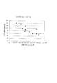
図10は吐出不良が発生時におけるそれまでの記録ヘッドによる記録行数と記録時間デューティ(duty)との関係を示す図である。なお、記録時間デューティ(duty)とは単位時間当たりの記録ドット数(dot/秒)である。
【0020】
図10から分かるように、単位時間当たりの記録ドット数が多いほうが、少ない場合よりも、より少ない記録行数で吐出不良が発生する、即ち、より早く吐出不良が発生する。
【0021】
さらに、記録ヘッドの内部温度を考慮すると、その温度が低くとも単位時間当たりの記録ドット数が多いほうが、その温度が高く単位時間当たりの記録ドット数が少ない場合よりも、吐出不良に対し不利となった。
【0022】
このように、単に記録ヘッド温度を検知して、吸引動作タイミングを決めるのでは十分でない。特に、インクジェット記録装置では、記録データの転送時に記録が待機状態になる場合には、上記の検討から分かるように、気泡の成長、即ち、吐出不良の発生は、記録ヘッド温度よりも、単位時間内の記録ドット数と高い相関がある。また、インクジェット記録装置が記録ヘッド温度がある一定温度より低い状態でのみ記録を許可する制御(以下、昇温検知)を実行する場合にも、記録ヘッド温度よりも記録時間dutyに依存して吐出不良が発生していた。
【0023】
即ち、量産されたインクジェット記録ヘッド個々には種々の記録特性に関してバラツキがあり、同じ記録データを入力して同じ画像を記録する場合にも、昇温しやすい記録ヘッドと昇温しにくい記録ヘッドとがある。従って、昇温しにくい記録ヘッドでは、昇温検知を実行しても、記録の許可がされることが、昇温しやすい記録ヘッドよりも多い。即ち、連続的に或いは単位時間内で記録動作が実行される割合が、昇温しやすい記録ヘッドよりも昇温しにくい記録ヘッドの方が高くなる。
【0024】
従って、昇温しにくく温度の低い記録ヘッドは、昇温しやすく温度が高い記録ヘッドよりも、記録ヘッド内気泡による吐出不良が発生しやすい状況になりやすい。このように、インクジェット記録装置においては、記録ヘッド温度が低い場合の方が高い場合より、記録ヘッド内気泡による吐出不良がしやすい場合があるので、従来の昇温検知では十分に吐出不良を防止することはできないという問題があった。
【0025】
また、吐出回数と放置時間と記録ヘッド温度から記録ヘッドの吸引動作時期を決定する従来の方法では、インクジェット記録装置が搭載するヘッド温度測定センサの温度測定精度が十分でないという問題点があった。
【0026】
つまり、センサにより記録装置が検知した記録ヘッド温度(検知温度)が低い状況でも、実際の記録ヘッド温度がその検知温度より高い場合があり、この場合には吸引動作が行われず、吐出不良を起こしてしまう場合があった。これとは反対に、記録装置が検知した記録ヘッド温度が高い状況でも、実際の記録ヘッド温度がその検知温度より低い場合があり、この場合には吸引動作の回数が必要以上に増え、記録動作のスループットが低下するのみならず、廃インク量が増加していまう場合があった。
【0027】
さらに、記録パターンによっては正確に吸引動作時期が定まらない場合があった。例えば、図11(a)に示すように、記録媒体の最初に高い記録画像dutyをもったパターンが記録され、その記録媒体の最後の方では低い記録画像dutyをもったパターンが記録された場合には、記録媒体全体にわたって均一の記録画像dutyをもったパターンが記録された場合と比較して、その記録媒体への記録終了時における記録ヘッド温度が低めに検知されてしまうために、吸引動作が行われず、吐出不良が発生してしまう場合があった。
【0028】
これとは反対に、図11(b)に示すように、記録媒体の最初に記録画像dutyの低いパターンがが記録され、その記録媒体の最後の方に記録画像dutyの高いパターンが記録された場合には、記録媒体全体にわたって均一の記録画像dutyをもったパターンが記録された場合と比較して、その記録媒体への記録終了時における記録ヘッド温度が高めに検知されてしまうために、吸引動作の回数が必要以上に増え、記録動作のスループットが低下し、廃インク量が増加してしまう場合があった。
【0029】
このような問題は記録媒体1頁中の記録において吸引回復動作を実行することで解決されるが、この吸引回復動作が発生すると記録ヘッド内のインクの状態を変化するので、記録媒体1頁の記録動作の途中で吸引回復動作を行うと、記録媒体上に記録された画像の色味が変化してしまう弊害がある。従って、記録媒体1頁の記録途中での吸引回復動作を実行させることが望ましくない。
【0030】
このように、インクジェット記録装置における記録ヘッド温度に従う記録制御は容易ではない。
【0031】
本発明は、上記従来例に鑑みてなされたもので、記録ヘッドを最適な状態に維持しながら、スループットの低下を最小限に抑え、さらに、廃インク量を増加させないことが可能なインクジェット記録装置及び吸引回復制御方法を提供することを目的としている。
【0032】
【課題を解決するための手段】
上記目的を達成するため本発明の吸引回復制御方法は、以下のような工程からなる。
【0033】
即ち、インクジェット記録装置で用いる記録ヘッドの吸引回復を制御する吸引回復制御方法であって、所定記録動作間隔における記録時間を計測する第1計測工程と、前記所定記録動作間隔において前記記録ヘッドからインク吐出を生じさせて記録がなされる記録ドット数を計測する第2計測工程と、前記第1及び第2計測工程において夫々計測された記録時間と記録ドット数とに基づいて、単位時間当たりの記録ドット数を算出する算出工程と、前記算出工程において算出された単位時間当たりの記録ドット数が第1の範囲にあるとき前記第2計測工程において計測された記録ドット数の値が該計測値より小さくなるように、そして、前記算出工程において算出された単位時間当たりの記録ドット数が前記第1の範囲より大きな値をもつ第2の範囲にあるとき前記第2計測工程において計測された記録ドット数の値が該計測値より大きくなるように、前記第2計測工程において計測された記録ドット数を補正する補正工程と、前記補正工程において補正された記録ドット数の累積値と第1の閾値とを比較する第1比較工程と、前記第1比較工程における比較結果に従って、前記累積値が前記第1の閾値以上の場合に、前記記録ヘッドの吸引回復を行うよう制御する制御工程とを有することを特徴とする吸引回復制御方法を備える。
【0034】
ここで、前記制御工程は、前記所定記録動作間隔での記録が終了する度毎に、前記第1比較工程における比較結果に従って、前記吸引回復の実行を制御することが望ましい。
【0035】
さらに、前記インクジェット記録装置に初めて電源が投入されてからの累積時間を計測する第3計測工程を含むと良い。
【0036】
この場合、記録媒体1頁分の記録が終了する度毎に、前記累積時間と第2の閾値を比較し、さらに、その比較結果に従って、前記吸引回復の実行を制御することが望ましい。
【0037】
なお、前記所定記録動作間隔は、記録媒体1頁分の記録動作間隔或いは記録ヘッド1走査分の記録動作間隔であることが望ましい。
【0039】
また、前記制御工程では、前記第1比較工程において前記累積値が前記第1の閾値以上と判断するか、或は前記第2比較工程において前記累積時間が前記第2の閾値以上と判断するかの内、いずれか早い方のタイミングにおいて、前記吸引回復を実行するよう制御すると良い。
【0040】
また他の発明によれば、インクジェット記録装置で用いる記録ヘッドの吸引回復を制御する吸引回復制御方法であって、所定記録領域毎に前記記録ヘッドからインク吐出を生じさせて記録がなされる記録ドット数を計測する第1計測工程と、前記第1計測工程において計測された記録ドット数と前記所定記録領域に記録可能な総ドット数とに基づいて、前記所定記録領域当たりの記録デューティを算出する算出工程と、前記算出工程において算出された前記所定記録領域当たりの記録デューティが第1の範囲にあるとき前記第1計測工程において計測された記録ドット数の値が該計測値より小さくなるように、そして、前記算出工程において算出された前記所定記録領域当たりの記録デューティが前記第1の範囲より大きな値をもつ第2の範囲にあるとき前記第1計測工程において計測された記録ドット数の値が該計測値より大きくなるように、第1計測工程において計測された記録ドット数を補正する補正工程と、前記補正工程において補正された記録ドット数の累積値と第1の閾値を比較する第1比較工程と、前記第1比較工程における比較結果に従って、前記累積値が前記第1の閾値以上の場合に、前記記録ヘッドの吸引回復を行うよう制御する制御工程とを有することを特徴とする吸引回復制御方法を備える。
【0041】
ここで、前記制御工程は、前記所定記録領域への記録が終了する度毎に、前記第1比較工程における比較結果に従って、前記記録ヘッドの吸引回復の実行を制御することが望ましい。
【0042】
さらに、前記インクジェット記録装置に初めて電源が投入されてからの累積時間を計測する第2計測工程を備えることが望ましい。
【0043】
その場合、前記所定記録領域への記録が終了する度毎に、さらに前記累積時間と第2の閾値を比較し、前記制御工程は、さらに、その比較結果に従って、前記吸引回復の実行を制御すると良い。
【0044】
なお、前記所定記録領域は、前記記録ヘッド1走査によって記録がなされる領域であることが望ましい。
【0045】
さらに他の発明によれば、インクジェット記録ヘッドを用いて記録媒体に記録を行う記録装置であって、前記インクジェット記録ヘッドの吸引回復を行う吸引回復手段と、所定記録動作間隔における記録時間を計測する第1計測手段と、前記所定記録動作間隔において前記インクジェット記録ヘッドからインク吐出を生じさせて記録がなされる記録ドット数を計測する第2計測手段と、前記第1及び第2計測手段によって夫々計測された記録時間と記録ドット数とに基づいて、単位時間当たりの記録ドット数を算出する算出手段と、前記算出手段によって算出された単位時間当たりの記録ドット数が第1の範囲にあるとき前記第2計測手段によって計測された記録ドット数の値が該計測値より小さくなるように、そして、前記算出手段によって算出された単位時間当たりの記録ドット数が前記第1の範囲より大きな値をもつ第2の範囲にあるとき前記第2計測手段によって計測された記録ドット数の値が該計測値より大きくなるように、前記第2計測手段によって計測された記録ドット数を補正する補正手段と、前記補正手段によって補正された記録ドット数の累積値と第1の閾値とを比較する第1比較手段と、前記第1比較手段による比較結果に従って、前記累積値が前記第1の閾値以上の場合に、前記吸引回復の動作を行うよう制御する制御手段とを有することを特徴とする記録装置を備える。
【0046】
さらに、前記記録装置に初めて電源が投入されてからの累積時間を計測する第3計測手段をさらに有し、前記制御手段は、その累積時間をさらに考慮して、前記吸引回復の実行を制御すると良い。
【0047】
またさらに他の発明によれば、インクジェット記録ヘッドを用いて記録媒体に記録を行う記録装置であって、前記インクジェット記録ヘッドの吸引回復を行う吸引回復手段と、所定記録領域毎に前記記録ヘッドからインク吐出を生じさせて記録がなされる記録ドット数を計測する第1計測手段と、前記第1計測手段によって計測された記録ドット数と前記所定記録領域に記録可能な総ドット数とに基づいて、前記所定記録領域当たりの記録デューティを算出する算出手段と、前記算出手段によって算出された前記所定記録領域当たりの記録デューティが第1の範囲にあるとき前記第1計測手段によって計測された記録ドット数の値が該計測値より小さくなるように、そして、前記算出手段によって算出された前記所定記録領域当たりの記録デューティが前記第1の範囲より大きな値をもつ第2の範囲にあるとき前記第1計測手段によって計測された記録ドット数の値が該計測値より大きくなるように、前記第1計測手段によって計測された記録ドット数を補正する補正手段と、前記補正手段によって補正された記録ドット数の累積値と第1の閾値を比較する第1比較手段と、前記第1比較手段による比較結果に従って、前記累積値が前記第1の閾値以上の場合に、前記記録ヘッドの吸引回復を行うよう制御する制御手段とを有することを特徴とする記録装置を備える。
【0048】
さらに、前記記録装置に初めて電源が投入されてからの累積時間を計測する第2計測手段をさらに有し、前記制御手段は、その累積時間をさらに考慮して、前記吸引回復の実行を制御すると良い。
【0049】
また、前記インクジェット記録ヘッドを往復走査する走査手段をさらに有する構成とする場合、前記所定記録領域は、その走査手段によってインクジェット記録ヘッドが1走査するときに記録がなされる領域であると良い。
【0050】
さて、以上の構成において言及した記録ヘッドは、熱エネルギーを利用してインクを吐出するために、インクに与える熱エネルギーを発生するための電気熱変換体を備えていることが望ましく、その電気熱変換体によって印加される熱エネルギーにより、インクに生ずる膜沸騰を利用して吐出口よりインクを吐出させると良い。
【0051】
以上の構成により本発明は、所定記録動作間隔における記録時間を計測し、その所定記録動作間隔において記録ヘッドからインク吐出を生じさせて記録がなされる記録ドット数を計測し、そのようにして、夫々計測された記録時間と記録ドット数とに基づいて、単位時間当たりの記録ドット数を算出し、その算出された単位時間当たりの記録ドット数に基づいて、吸引回復のタイミングを決定して記録ヘッドの吸引回復を行うよう制御する。
【0052】
また他の発明によれば、所定記録領域毎に記録ヘッドからインク吐出を生じさせて記録がなされる記録ドット数を計測し、その計測された記録ドット数と所定記録領域に記録可能な総ドット数とに基づいて、単位記録領域当たりの記録ドット数を算出し、その算出された単位記録領域当たりの記録ドット数に基づいて、吸引回復のタイミングを決定して記録ヘッドの吸引回復を行うよう制御する。
【0053】
【発明の実施の形態】
以下添付図面を参照して本発明の好適な実施形態について詳細に説明する。
【0054】
なお、この実施形態では、記録画像デューティ(duty)を以下のように定義している。即ち、記録画像デューティ(duty)とは単位記録範囲内におけるインク吐出を伴う記録ドット数であり、例えば、A4用紙に記録ヘッド1走査分(1行)の記録をする間の実際のインク吐出回数のことを言う。この場合、この値は、単位記録範囲を構成する総ドット数に対する比率として表しても良い。
【0055】
また、記録時間デューティ(duty)とはインク吐出を伴う記録ドット数をその記録ドット数を記録するのに要した記録時間で割ったものである。例えば、10000個の記録ドットをインク吐出によって記録させた場合に、その10000個のドットを記録するのに要した時間で割ったものである。ここで、その記録に要した時間は、1個目のドットを記録するのに記録ヘッドがインクを吐出してから、10000個目のドットを記録するのに記録ヘッドがインクを吐出させ終わるまでの時間でも良いし、また、記録装置が扱いやすいタイミング、例えば給紙終了時から排紙開始時のようなものでも良い。前もってそのタイミングに合わせて、記録画像デューティ(duty)と吐出不良の関係が明確になっていれば良い。
【0056】
<第1実施形態>
図1は、本発明の代表的な実施の形態であるインクジェットプリンタIJRAの構成の概要を示す外観斜視図である。図1において、駆動モータ5013の正逆回転に連動して駆動力伝達ギア5009〜5011を介して回転するリードスクリュー5005の螺旋溝5004に対して係合するキャリッジHCはピン(不図示)を有し、ガイドレール5003に支持されて矢印a,b方向を往復移動する。キャリッジHCには、記録ヘッドIJHとインクタンクITとを内蔵した一体型インクジェットカートリッジIJCが搭載されている。5002は紙押え板であり、キャリッジHCの移動方向に亙って記録用紙Pをプラテン5000に対して押圧する。5007,5008はフォトカプラで、キャリッジのレバー5006のこの域での存在を確認して、モータ5013の回転方向切り換え等を行うためのホームポジション検知器である。5016は記録ヘッドIJHの前面をキャップするキャップ部材5022を支持する部材で、5015はこのキャップ内を吸引する吸引器で、キャップ内開口5023を介して記録ヘッドの吸引回復を行う。5017はクリーニングブレードで、5019はこのブレードを前後方向に移動可能にする部材であり、本体支持板5018にこれらが支持されている。ブレードは、この形態でなく周知のクリーニングブレードが本例に適用できることは言うまでもない。又、5021は、吸引回復の吸引を開始するためのレバーで、キャリッジと係合するカム5020の移動に伴って移動し、駆動モータからの駆動力がクラッチ切り換え等の公知の伝達機構で移動制御される。
【0057】
これらのキャッピング、クリーニング、吸引回復は、キャリッジがホームポジション側の領域に来た時にリードスクリュー5005の作用によってそれらの対応位置で所望の処理が行えるように構成されているが、周知のタイミングで所望の動作を行うようにすれば、本例にはいずれも適用できる。
【0058】
<制御構成の説明>
次に、上述した装置の記録制御を実行するための制御構成について説明する。
【0059】
図2はインクジェットプリンタIJRAの制御回路の構成を示すブロック図である。制御回路を示す同図において、1700は記録信号を入力するインタフェース、1701はMPU、1702はMPU1701が実行する制御プログラムを格納するROM、1703は各種データ(上記記録信号やヘッドに供給される記録データ等)を保存しておくDRAMである。1704は記録ヘッドIJHに対する記録データの供給制御を行うゲートアレイ(G.A.)であり、インタフェース1700、MPU1701、RAM1703間のデータ転送制御も行う。1710は記録ヘッドIJHを搬送するためのキャリアモータ、1709は記録紙搬送のための搬送モータである。1705は記録ヘッドIJHを駆動するヘッドドライバ、1706,1707はそれぞれ搬送モータ1709、キャリアモータ1710を駆動するためのモータドライバである。
【0060】
上記制御構成の動作を説明すると、インタフェース1700に記録信号が入るとゲートアレイ1704とMPU1701との間で記録信号がプリント用の記録データに変換される。そして、モータドライバ1706、1707が駆動されると共に、ヘッドドライバ1705に送られた記録データに従って記録ヘッドIJHが駆動され、記録が行われる。
【0061】
また、回復制御部1708は、MPU1701からの制御のもと、キャップ5022を用いた記録ヘッドIJHの前面のキャッピング、クリーニングブレード5017による記録ヘッドIJHの前面の清浄、吸引器5015による記録ヘッドIJHの吸引回復の動作など一連の回復動作を制御する。
【0062】
さて、ドットカウンタ1712では記録動作中に記録ヘッドIJHからインクが吐出されて記録が行われた記録ドット数を計数しており、その計数値が記録動作の進行に連れて回復制御部1708に信号として出力される。
【0063】
一方、タイムカウンタ1711aは、記録時間をカウントし、そのカウント結果を回復制御部1708に出力する。さらに、タイムカウンタ1711bは、インクジェットプリンタIJRAに初めて電源が投入された時点からのインクジェット記録装置の放置時間をカウントし、そのカウント結果を回復制御部1708に出力する。
【0064】
回復制御部1708では、タイムカウンタ1711aから得られるカウント結果、タイムカウンタ1711bから得られるカウント結果、ドットカウンタ1712から得られる記録ドット数に基づいて、吸引器5015とMPU1701に吸引動作命令を送る。
【0065】
なお、上述のように、インクタンクITと記録ヘッドIJHとは一体的に形成されて交換可能なインクカートリッジIJCを構成しても良いが、これらインクタンクITと記録ヘッドIJHとを分離可能に構成して、インクがなくなったときにインクタンクITだけを交換できるようにしても良い。
【0066】
図3は、インクタンクとヘッドとが分離可能なインクカートリッジIJCの構成を示す外観斜視図である。インクカートリッジIJCは、図3に示すように、境界線Kの位置でインクタンクITと記録ヘッドIJHとが分離可能である。インクカートリッジIJCにはこれがキャリッジHCに搭載されたときには、キャリッジHC側から供給される電気信号を受け取るための電極(不図示)が設けられており、この電気信号によって、前述のように記録ヘッドIJHが駆動されてインクが吐出される。
【0067】
なお、図3において、500はインク吐出口列である。また、インクタンクITにはインクを保持するために繊維質状もしくは多孔質状のインク吸収体が設けられており、そのインク吸収体によってインクが保持される。
【0068】
次に、上述した記録ヘッドIJHについて図4を参照して説明する。
【0069】
図4は、図1に示したインクジェットカートリッジIJCを構成する記録ヘッドIJHの要部斜視図である。
【0070】
記録ヘッドIJHは、図4に示すように、記録紙P(図1参照)と所定の間隔をおいて対面する吐出口面1aに、所定のピッチで複数の吐出口1bが形成されている。図4において、4は電気熱変換素子1eおよびインク供給口1fを備える基板であり、長溝状の貫通口からなるインク供給口1fの長手方向の両側に吐出エネルギー発生素子である電気熱変換素子1がそれぞれ1列ずつ千鳥状に配列されており、共通液室1cと各吐出口1bは各液路1dで連通されている。
【0071】
また、共通液室1cは、インクジェットカートリッジIJCのインクタンクITと連通しており、共通液室1cにはインクタンクITからインクが供給される構成となっている。インクタンクITから共通液室1cに供給されて一時的に貯えられたインクは、毛管現象により液路1dに侵入し、吐出口1bでメニスカスを形成して液路1dを満たした状態を保つ。
【0072】
このとき、電極(不図示)を介して電気熱変換素子1eが通電されて発熱すると、電気熱変換素子1e上のインクが急激に加熱されて液路1d内に気泡が発生し、この気泡の膨張により吐出口1bからインクが吐出される。
【0073】
なお、この実施形態において、記録ヘッドIJHに形成される吐出口1bの数は256個であり、インクジェットプリンタIJRAは、最大A3サイズの記録紙に対して記録が可能であり、その記録解像度は1200DPIで、駆動周波数は10kHzである。
【0074】
次に、以上のような構成のインクジェットプリンタIJRAの吸引動作制御手順について図5に示すフローチャートを参照して説明する。
【0075】
まず、ステップS101では、インクジェットプリンタIJRAに初めて電源が投入されたかどうかを調べ、それが初めての電源投入であれば、処理はステップS102に進み、タイムカウンタ1711bによる放置時間(t2)のカウントを開始する。このカウントはインクジェットプリンタIJRAの電源供給が切断されても続行される。その後、処理はステップS103へと進む。これに対して、それが初めての電源投入ではないなら、処理はステップS102をスキップしてそのままステップS103へと進む。
【0076】
ステップS103では、電源投入後、カウントされた放置時間(t2)と吸引放置時間閾値(t2th)を比較する。吸引放置時間閾値(t2th)は、前もって記録ヘッドに吐出不良が発生するまでのインクジェットプリンタの放置時間を検討することにより求めておき、ROM1702に設定しておく。
【0077】
ここで、t2≧t2thである場合には、処理はステップS116に進む。ステップS116以降の処理については後述する。、
これに対して、t2<t2thとである場合には、処理はステップS104に進み、タイムカウンタ1711aによる記録時間の計測値(t1)を初期化し、さらに、ステップS105ではドットカウンタ1712による記録ドット数のカウント値(X)を初期化する。次に、ステップS106では記録動作が開始されるかどうかを調べ、開始されないのであれば処理はステップS103に戻り、開始されるのであれば、処理はステップS107に進む。
【0078】
ステップS107では、記録開始と同時にタイムカウンタ1711aによる記録時間(t1)のカウントを開始し、さらに、ステップS108では、ドットカウンタ1712により記録ドット数(X)のカウントを開始する。なお、この実施形態では、記録時間(t1)のカウントを開始する具体的なタイミングは、インクジェットプリンタIJRAへの記録用紙の給紙が終了した時点である。
【0079】
次に、処理はステップS109において、記録用紙1枚分の記録の終了を待ち合わせ、その記録が終了すると、処理はステップS110に進み、タイムカウンタ1711aによる記録時間(t1)のカウントを終了する。そして、ステップS111では、式(1)に従って記録時間デューティ(duty)を計算する。
【0080】
X/t1 …(1)
さらに、ステップS111では、計算された記録時間デューティ(duty)の値(X/t1)に基づいて、表1に示すテーブルを参照して補正係数(α)を求める。補正係数(α)は、前もって検討により求めておいたものである。具体的には、式(1)より求まる種々の(X/t1)の値に対して、補正係数(α)を求めるために、記録画像デューティ(duty)を変化させたり、記録パターンを記録用紙の前半に偏らせて記録するなどしてもとめる。この実施形態では、図10に示したように、単位時間あたりの記録ドット数と吐出不良との関係に基づき、補正係数(α)と以下に説明する補正記録ドットカウント値(Y)の閾値(Yth)を決めている。
【0081】
【表1】

【0082】
Y=Y+X+αX …(2)
ステップS113では、補正記録ドットカウント値(Y)とその閾値(Yth)を比較する。ここで、Y≧Ythである場合には処理はステップS116に進む。これに対して、Y<Ythである場合には、処理はステップS114に進み、放置時間(t2)と吸引放置時間閾値(t2th)を比較する。ここで、t2≧t2thである場合には、処理はステップS116に進む。これに対して、t2<t2thである場合には、処理はステップS115に進み、記録動作を終了するかどうかを調べる。ここで、次に記録するデータが存在しない場合は、記録動作を終了し、まだ未記録データが存在する場合には、処理はステップS103に戻り、上述した処理をデータが存在しなくなるまで繰り返す。
【0083】
さて、ステップS116では、回復制御部1708から吸引動作命令をMPU1701と吸引器5015に送る。一方、MPU1701はステップS116において、吸引動作命令を受信すると、記録動作を中断し、キャリアモータ1710を駆動して記録ヘッドIJHを搭載したキャリッジHCをキャップ5022に対向する位置に移動させて吸引動作に備えるよう制御するとともに、キャップ5022により記録ヘッドIJHの吐出口面をキャッピングするよう制御する。そして、回復制御部1708はMPU1701と連携をとりながら、吸引器5015を動作せて吸引動作を行う。
【0084】
その後、処理はステップS117に進み、これまでにカウントされた放置時間(t2)と補正記録ドットカウント値(Y)の値を初期化する。その後、処理はステップS115に戻る。
【0085】
従って以上説明した実施形態によれば、吸引動作が必要であるかどうかを、記録用紙1枚分の記録が終了するたび毎に、単位記録時間当たりの記録ドット数によって補正された記録ドット数および放置時間に従って決定するので、記録ヘッドを最適な状態に保つための吸引動作の回数が必要最小限の回数ですみ、記録ヘッドを最適な状態に保ちつつ、インクジェットプリンタのスループットの低下を最小限に抑えることができる。また、吸引動作の回数を必要最小限に抑えることで廃インク量を抑えることができ、インク消費量の削減や運用コストの削減にも資することができる。
【0086】
なお、この実施形態では、表1に示すような補正係数(α)を用いたが、補正係数は、記録ヘッドの共通液室容積、吐出ノズル数、放熱設計等により変わるものであり、また、記録ヘッドの動作を制御するときの駆動周波数等により変わるものであるので、基本的には各インクジェットプリンタの仕様に依存したものとなる。従って、本発明はこの実施形態で示した補正係数によって限定されるものではない。
【0087】
また、この実施形態では記録時間(t2)のカウントを開始する具体的なタイミングをインクジェットプリンタへの記録用紙の給紙が終了した時点としたが、本発明はこれによって限定されるものではなく、例えば、キャリッジHCが主走査方向に移動を開始する時点にする等、記録装置の構成に沿った別のタイミングでもかまわない。
【0088】
さらに、この実施形態では説明しなかったが、記録ヘッドの温度がある一定温度より低い状態でのみ記録を許可する制御(昇温検知)をインクジェットプリンタが採用していてもよい。
【0089】
またさらに、この実施形態では、各カウンタ値の比較結果に基づいて吸引動作を行なうように制御する例について説明したが、本発明はこれによって限定されるものではない。例えば、装置への電源投入後に必ず吸引動作を実行し、放置中に粘度の増した或いは固着したインクを取り除くようにしてもよい。
【0090】
またさらに、図5に示したフローチャートの処理では、記録用紙1枚分の記録が終了するたびに(X/t1)の値を求めたが、本発明はこれによって限定されるものではない。例えば、図6のステップS109aに示すように、記録ヘッド1走査分の記録(即ち、1行分)が終了するたびごとに(X/t1)の値を求め、記録ドット数の補正を記録一行終了毎に行うように制御しても良い。この場合には、カウントされる記録時間(t1)は、記録ヘッドを搭載したキャリッジが1行分の記録を終了した行末から次の行末までの時間でよい。このため、図6に示すフローチャートにはこのような制御を行うために、ステップS112aの処理が追加されている。
【0091】
なお、図6に示すフローチャートでは、ステップS109aとS112aの処理以外の処理は図5に示した処理と共通であるので、それらの共通した処理については同じステップ参照番号を付し、その説明は省略する。
【0092】
またさらに、放置中の記録ヘッド内での気泡の成長が少ない場合には、インクジェットプリンタIJRAの制御回路からタイムカウンタ1711bを除き、放置時間(t2)の測定をしないようにすることも可能である。その場合、図5に示したフローチャートの処理は、図7のフローチャートに示すように、放置時間(t2)に関連した処理の除かれた処理構成となる。即ち、その処理では、吸引動作のタイミングは、記録時間デューティ(duty)から求められる構成となる。
【0093】
<第2実施形態>
ここでは、第1実施形態のインクジェットプリンタの制御回路の構成に比較して、1つのタイムカウンタを用いない構成の制御回路を用いた例について説明する。
【0094】
図8はインクジェットプリンタIJRAの制御回路の構成を示すブロック図である。この制御回路の構成は、上述のように図2に示した構成と比較して、タイムカウンタ1711aがないだけであるので、図2に示したのと同じ構成要素には同じ参照番号を付し、その説明は省略する。つまり、この実施形態では、記録時間(t1)についての測定は行わない。
【0095】
次に、図9に示すフローチャートを参照して、この実施形態に従う吸引動作制御について説明する。なお、図9に示すフローチャートは、図5に示したフローチャートと比較して、共通の処理ステップが多く含まれている。従って、その共通の処理ステップには同じステップ参照番号を付し、その説明は省略する。ここでは、この実施形態に特徴的な処理ステップについてのみ説明する。
【0096】
図5に示したタイムカウンタ1711aの初期化を行うステップS104の処理とタイムカウンタ1711aによる記録時間(t1)のカウント開始処理を行うステップS107の処理を除き、ステップS101〜S108の処理は、第1実施形態と同様に実行される。
【0097】
その後、処理はステップS109Aにおいて、記録ヘッドIJHの1走査分の記録(即ち、1行分の記録)の完了を待ち合わせ、その記録が完了したなら、処理はステップS110Aに進む。
【0098】
ステップS110Aでは、式(3)に従って、記録画像デューティ(duty)を計算する。
【0099】
X/Xa11 …(3)
ここで、Xa11は、100%の画像記録デューティ(duty)で記録がなされた場合のドット数、即ち、単位記録範囲(記録ヘッドIJHによる1走査範囲)を構成する総ドット数である。
【0100】
次に、ステップS111Aでは、得られた記録画像デューティ(duty)をキーとして、表1に示したテーブルと類似した記録画像デューティ(duty)の種々の値とその各々の値に対応した補正係数(α)との関係を示したテーブルを検索して補正係数(α)を求める。この補正係数(α)は、第1実施形態の場合と同様に、記録画像デューティ(duty)を変えたり、記録パターンを記録用紙の前半に偏らせて記録させるなどして前もって検討により求めておいたものである。
【0101】
この処理後、第1実施形態と同様に、ステップS113〜S117の処理を実行する。
【0102】
従って以上説明した実施形態に従えば、記録ヘッドによる1走査分の記録動作が終了するたび毎に吸引動作が必要かどうかを、単位記録範囲当たりの記録ドット数、即ち、記録画像デューティに従って補正した記録ドット数と、放置時間とに従って決定するので、記録ヘッドを最適な状態に保つための吸引動作の回数が必要最小限の回数ですみ、記録ヘッドを最適な状態に保ちつつ、インクジェットプリンタのスループットの低下を最小限に抑えることができる。また、吸引動作の回数を必要最小限に抑えることで廃インク量を抑えることができ、インク消費量の削減や運用コストの削減にも資することができる。
【0103】
しかしながら、画像記録動作中に、画像データによる転送の動作待機が発生したり、昇温検知等により記録が待機状態になる場合には、記録時間デューティ(duty)により記録ドット数を補正する方が好ましい。
【0104】
なお、以上の実施形態において、記録ヘッドから吐出される液滴はインクであるとして説明し、さらにインクタンクに収容される液体はインクであるとして説明したが、その収容物はインクに限定されるものではない。例えば、記録画像の定着性や耐水性を高めたり、その画像品質を高めたりするために記録媒体に対して吐出される処理液のようなものがインクタンクに収容されていても良い。
【0105】
以上の実施形態は、特にインクジェット記録方式の中でも、インク吐出を行わせるために利用されるエネルギーとして熱エネルギーを発生する手段(例えば電気熱変換体やレーザ光等)を備え、前記熱エネルギーによりインクの状態変化を生起させる方式を用いることにより記録の高密度化、高精細化が達成できる。
【0106】
その代表的な構成や原理については、例えば、米国特許第4723129号明細書、同第4740796号明細書に開示されている基本的な原理を用いて行うものが好ましい。この方式はいわゆるオンデマンド型、コンティニュアス型のいずれにも適用可能であるが、特に、オンデマンド型の場合には、液体(インク)が保持されているシートや液路に対応して配置されている電気熱変換体に、記録情報に対応していて膜沸騰を越える急速な温度上昇を与える少なくとも1つの駆動信号を印加することによって、電気熱変換体に熱エネルギーを発生せしめ、記録ヘッドの熱作用面に膜沸騰を生じさせて、結果的にこの駆動信号に1対1で対応した液体(インク)内の気泡を形成できるので有効である。この気泡の成長、収縮により吐出用開口を介して液体(インク)を吐出させて、少なくとも1つの滴を形成する。この駆動信号をパルス形状をすると、即時適切に気泡の成長収縮が行われるので、特に応答性に優れた液体(インク)の吐出が達成でき、より好ましい。
【0107】
このパルス形状の駆動信号としては、米国特許第4463359号明細書、同第4345262号明細書に記載されているようなものが適している。なお、上記熱作用面の温度上昇率に関する発明の米国特許第4313124号明細書に記載されている条件を採用すると、さらに優れた記録を行うことができる。
【0108】
記録ヘッドの構成としては、上述の各明細書に開示されているような吐出口、液路、電気熱変換体の組み合わせ構成(直線状液流路または直角液流路)の他に熱作用面が屈曲する領域に配置されている構成を開示する米国特許第4558333号明細書、米国特許第4459600号明細書を用いた構成も本発明に含まれるものである。加えて、複数の電気熱変換体に対して、共通するスロットを電気熱変換体の吐出部とする構成を開示する特開昭59−123670号公報や熱エネルギーの圧力波を吸収する開口を吐出部に対応させる構成を開示する特開昭59−138461号公報に基づいた構成としても良い。
【0109】
さらに、記録装置が記録できる最大記録媒体の幅に対応した長さを有するフルラインタイプの記録ヘッドとしては、上述した明細書に開示されているような複数記録ヘッドの組み合わせによってその長さを満たす構成や、一体的に形成された1個の記録ヘッドとしての構成のいずれでもよい。
【0110】
加えて、上記の実施形態で説明した記録ヘッド自体に一体的にインクタンクが設けられたカートリッジタイプの記録ヘッドのみならず、装置本体に装着されることで、装置本体との電気的な接続や装置本体からのインクの供給が可能になる交換自在のチップタイプの記録ヘッドを用いてもよい。
【0111】
また、以上説明した記録装置の構成に、記録ヘッドに対する回復手段、予備的な手段等を付加することは記録動作を一層安定にできるので好ましいものである。これらを具体的に挙げれば、記録ヘッドに対してのキャッピング手段、クリーニング手段、加圧あるいは吸引手段、電気熱変換体あるいはこれとは別の加熱素子あるいはこれらの組み合わせによる予備加熱手段などがある。また、記録とは別の吐出を行う予備吐出モードを備えることも安定した記録を行うために有効である。
【0112】
さらに、記録装置の記録モードとしては黒色等の主流色のみの記録モードだけではなく、記録ヘッドを一体的に構成するか複数個の組み合わせによってでも良いが、異なる色の複色カラー、または混色によるフルカラーの少なくとも1つを備えた装置とすることもできる。
【0113】
以上説明した実施の形態においては、インクが液体であることを前提として説明しているが、室温やそれ以下で固化するインクであっても、室温で軟化もしくは液化するものを用いても良く、あるいはインクジェット方式ではインク自体を30°C以上70°C以下の範囲内で温度調整を行ってインクの粘性を安定吐出範囲にあるように温度制御するものが一般的であるから、使用記録信号付与時にインクが液状をなすものであればよい。
【0114】
加えて、積極的に熱エネルギーによる昇温をインクの固形状態から液体状態への状態変化のエネルギーとして使用せしめることで積極的に防止するため、またはインクの蒸発を防止するため、放置状態で固化し加熱によって液化するインクを用いても良い。いずれにしても熱エネルギーの記録信号に応じた付与によってインクが液化し、液状インクが吐出されるものや、記録媒体に到達する時点では既に固化し始めるもの等のような、熱エネルギーの付与によって初めて液化する性質のインクを使用する場合も本発明は適用可能である。このような場合インクは、特開昭54−56847号公報あるいは特開昭60−71260号公報に記載されるような、多孔質シート凹部または貫通孔に液状または固形物として保持された状態で、電気熱変換体に対して対向するような形態としてもよい。本発明においては、上述した各インクに対して最も有効なものは、上述した膜沸騰方式を実行するものである。
【0115】
さらに加えて、本発明に係る記録装置の形態としては、コンピュータ等の情報処理機器の画像出力端末として一体または別体に設けられるものの他、リーダ等と組み合わせた複写装置、さらには送受信機能を有するファクシミリ装置の形態を取るものであっても良い。
【0116】
なお、本発明は、複数の機器(例えばホストコンピュータ,インタフェース機器,リーダ,プリンタなど)から構成されるシステムに適用しても、一つの機器からなる装置(例えば、複写機,ファクシミリ装置など)に適用してもよい。
【0117】
また、本発明の目的は、前述した実施形態の機能を実現するソフトウェアのプログラムコードを記録した記憶媒体を、システムあるいは装置に供給し、そのシステムあるいは装置のコンピュータ(またはCPUやMPU)が記憶媒体に格納されたプログラムコードを読出し実行することによっても、達成されることは言うまでもない。
【0118】
この場合、記憶媒体から読出されたプログラムコード自体が前述した実施形態の機能を実現することになり、そのプログラムコードを記憶した記憶媒体は本発明を構成することになる。
【0119】
プログラムコードを供給するための記憶媒体としては、例えば、フロッピディスク,ハードディスク,光ディスク,光磁気ディスク,CD−ROM,CD−R,磁気テープ,不揮発性のメモリカード,ROMなどを用いることができる。
【0120】
また、コンピュータが読出したプログラムコードを実行することにより、前述した実施形態の機能が実現されるだけでなく、そのプログラムコードの指示に基づき、コンピュータ上で稼働しているOS(オペレーティングシステム)などが実際の処理の一部または全部を行い、その処理によって前述した実施形態の機能が実現される場合も含まれることは言うまでもない。
【0121】
さらに、記憶媒体から読出されたプログラムコードが、コンピュータに挿入された機能拡張ボードやコンピュータに接続された機能拡張ユニットに備わるメモリに書込まれた後、そのプログラムコードの指示に基づき、その機能拡張ボードや機能拡張ユニットに備わるCPUなどが実際の処理の一部または全部を行い、その処理によって前述した実施形態の機能が実現される場合も含まれることは言うまでもない。
【0122】
【発明の効果】
以上説明したように本発明によれば、所定記録動作間隔における記録時間を計測し、その所定記録動作間隔において記録ヘッドからインク吐出を生じさせて記録がなされる記録ドット数を計測し、そのようにして、夫々計測された記録時間と記録ドット数とに基づいて、単位時間当たりの記録ドット数を算出し、その算出された単位時間当たりの記録ドット数に基づいて、吸引回復のタイミングを決定して記録ヘッドの吸引回復を行うよう制御したり、或いは、所定記録領域毎に記録ヘッドからインク吐出を生じさせて記録がなされる記録ドット数を計測し、その計測された記録ドット数と所定記録領域に記録可能な総ドット数とに基づいて、単位記録領域当たりの記録ドット数を算出し、その算出された単位記録領域当たりの記録ドット数に基づいて、吸引回復のタイミングを決定して記録ヘッドの吸引回復を行うよう制御するので、その時点時点での実際の記録動作が用いている記録ヘッドに対する影響を考慮して、記録ヘッドの吸引回復のタイミングを定めることができる。
【0123】
従って、例えば、記録ヘッドの温度特性などが個々にばらついたとしても、そのような特性に左右されず、正確に吸引回復タイミングを定めることができるという効果がある。これにより、必要最小限の吸引回復動作を実行することで記録ヘッドを最適な状態に維持され、記録動作におけるスループットの低下を最小限に抑え、さらに、吸引回復動作に伴う廃インク量を増加させないことが可能となる。
【0124】
さらに、記録ヘッドの温度検知機能を備えた構成の記録装置においても、例えば、その温度検知精度や、記録データやその記録パターンがその温度検知に影響を与え、その結果、記録ヘッドの吸引回復のタイミングに悪影響を及ぼすといったことが防止される。
【図面の簡単な説明】
【図1】本発明の代表的な実施の形態であるインクジェットプリンタIJRAの構成の概要を示す外観斜視図である。
【図2】第1実施形態に従うインクジェットプリンタIJRAの制御回路の構成を示すブロック図である。
【図3】インクタンクとヘッドとが分離可能なインクカートリッジIJCの構成を示す外観斜視図である。
【図4】図1に示したインクジェットカートリッジIJCを構成する記録ヘッドIJHの要部斜視図である。
【図5】第1実施形態に従う吸引動作制御手順を示すフローチャートである。
【図6】第1実施形態の変形例に従う吸引動作制御手順を示すフローチャートである。
【図7】第1実施形態の別の変形例に従う吸引動作制御手順を示すフローチャートである。
【図8】第2実施形態に従うインクジェットプリンタIJRAの制御回路の構成を示すブロック図である。
【図9】第2実施形態に従う吸引動作制御手順を示すフローチャートである。
【図10】吐出不良が発生時におけるそれまでの記録ヘッドによる記録行数と記録時間デューティ(duty)との関係を示す図である。
【図11】記録媒体1頁中で記録デューティが大きく変化する記録パターンの例を示す図である。
【符号の説明】
1700 インタフェース
1701 MPU
1702 ROM
1703 DRAM
1704 ゲートアレイ(G.A.)
1705 ヘッドドライバ
1706、1707 モータドライバ
1708 回復制御部
1709 搬送モータ
1710 キャリアモータ
1711a、1711b タイムカウンタ
1712 ドットカウンタ
5015 吸引器
5017 クリーニングブレード
5022 キャップ
IJC インクカートリッジ
IJH 記録ヘッド
IT インクタンク[0001]
BACKGROUND OF THE INVENTION
The present invention relates to a recording apparatus and a suction recovery control method, and more particularly to a recording apparatus using a recording head that performs recording according to an ink jet recording method and a suction recovery control method.
[0002]
[Prior art]
A recording device used in a printer unit such as a printer device, a copying machine, or a facsimile device, creates an image formed by a dot pattern on a recording medium such as paper, a plastic thin plate, or a fabric based on input image information. Record.
[0003]
Such a recording apparatus can be classified into an ink jet method, a wire dot method, a thermal method, a laser beam method, and the like according to the recording method.
[0004]
Among them, the ink jet method performs recording by ejecting ink from a recording head onto a recording medium, and not only can record high-definition images at high speed, but also operates because it is a non-impact method. There are advantages such as low noise and easy to print a color image using multi-color ink.
[0005]
Furthermore, among inkjet systems, the bubble jet system, in which ink is heated to cause film boiling and the ink is ejected by the pressure of bubbles generated at that time, is known as being capable of realizing high-resolution recording and high-speed recording more easily. It has been.
[0006]
In an ink jet recording apparatus that uses ink as a recording agent for recording, there is a technology for maintaining the reliability of the ink ejection function from the recording head in order to prevent adverse effects on recording due to evaporation of ink or mixing of bubbles. It becomes important.
[0007]
Specifically, when the ink jet recording apparatus is in a recording operation or is left standing, bubbles are gradually generated in the ink discharge nozzles or the fitting portion of the recording head, so that ink discharge becomes impossible (non-discharge). In some cases, ejection failure may occur and normal recording cannot be performed. Therefore, in order to remove the bubbles, a head recovery device having a cap for capping the recording head and a suction pump for sucking the inside of the cap is provided, and the ink discharge surface of the recording head is arranged at a position where the cap and the recording head face each other. After capping, a configuration is adopted in which bubbles in the recording head are sucked by a suction pump. This suction recovery process is an important technique as a technique for maintaining the reliability of the ink jet recording apparatus.
[0008]
However, even if the suction conditions are determined so that the optimum bubble removal performance is exhibited for the head recovery device, the volume of the bubbles during different suction operations varies, so the same bubble removal capability is always available. Does not demonstrate. Therefore, in the conventional ink jet recording apparatus, in order to maintain a good bubble removal capability, the number of ejection times, the time count of the standing time, or the number of ejection times so that suction is performed with the bubble volume as constant as possible. Both counting and standing time are measured, and the suction operation is controlled according to these measured values. More specifically, the suction operation timing of the recording head is determined based on the earlier of the time when a predetermined time has elapsed from the initial time and the time when the predetermined amount of recording has been completed from the initial time.
[0009]
In Japanese Patent Laid-Open No. 6-238914, in consideration of the difference in the amount of bubbles generated in the head due to the rise in the internal temperature of the recording head, the suction operation of the recording head is determined from the number of ejections, the standing time, and the temperature of the recording head. It proposes a method to determine the timing.
[0010]
[Problems to be solved by the invention]
However, in the reliability maintaining technology employed in the conventional ink jet recording apparatus, the number of ejections per unit recording range by the recording head (for example, the actual number of ejections while recording an image for one line on A4 paper. , Recording image duty) is not considered. For this reason, depending on the recording image duty, not only an unnecessary suction operation is performed to reduce the throughput of the recording apparatus, but also the amount of waste ink is increased, or conversely due to bubbles before the suction operation is performed. There has been a problem that ejection failure may occur.
[0011]
In particular, the bubble jet method heats the ink locally to cause film boiling, thereby generating ink ejection force, so that the internal temperature of the recording head gradually increases by performing the recording operation. As a result of this temperature rise, the bubble generation state and growth rate change. Therefore, as in the above-described conventional example, a method of determining the recording head suction operation timing from the number of ejections, the standing time, and the recording head temperature has also been proposed.
[0012]
However, this method also has the following problems.
[0013]
(1) The temperature rise of the recording head varies from head to head.
[0014]
(2) There is a variation in the temperature detection of the recording head, and accurate control is difficult.
[0015]
(3) The internal temperature of the recording head varies depending on the pattern of the recording image.
[0016]
In the following, these three problems will be described in detail.
[0017]
A detailed study of the cause and generation mechanism of bubbles in the recording head, which is the cause of ejection failure, revealed the following.
[0018]
When a recording operation is performed with an ink jet recording head, small bubbles are initially generated in the recording head, and then, the bubbles merge to grow into large bubbles. However, the first generated bubbles are dissolved in the ink and disappear if the ink is not ejected from the recording head after the generation. From this, as a condition for the bubbles to merge and grow, it can be considered that the recording head repeats ink ejection within a certain time before the bubbles disappear. That is, when a large amount of ink is ejected within a unit time with the recording head, bubbles before disappearance coalesce and grow, resulting in ejection failure.
[0019]
FIG. 10 is a diagram showing the relationship between the number of recording rows by the recording head and the recording time duty (duty) when an ejection failure occurs. The recording time duty (duty) is the number of recording dots per unit time (dot / second).
[0020]
As can be seen from FIG. 10, when the number of recording dots per unit time is large, ejection failure occurs with a smaller number of recording lines than when the number is small, that is, ejection failure occurs earlier.
[0021]
Furthermore, considering the internal temperature of the recording head, even if the temperature is low, a larger number of recording dots per unit time is more disadvantageous for ejection defects than when the temperature is high and the number of recording dots per unit time is small. became.
[0022]
Thus, it is not sufficient to determine the suction operation timing simply by detecting the print head temperature. In particular, in the ink jet recording apparatus, when recording is in a standby state at the time of transfer of recording data, as can be seen from the above examination, the bubble growth, that is, the occurrence of the ejection failure is a unit time rather than the recording head temperature. There is a high correlation with the number of recorded dots. Also, when the ink jet recording apparatus performs control (hereinafter, temperature rise detection) that permits recording only when the recording head temperature is lower than a certain temperature, ejection is performed depending on the recording time duty rather than the recording head temperature. There was a defect.
[0023]
That is, there are variations in various recording characteristics among the mass-produced inkjet recording heads, and even when the same recording data is input and the same image is recorded, a recording head that easily rises in temperature and a recording head that hardly rises in temperature There is. Accordingly, in a recording head that is difficult to increase in temperature, even when temperature increase detection is executed, recording is permitted more frequently than in a recording head that is likely to increase in temperature. That is, the rate at which the recording operation is executed continuously or within a unit time is higher for a recording head that is less likely to be heated than for a recording head that is likely to increase in temperature.
[0024]
Therefore, a recording head that is difficult to increase in temperature and has a low temperature is more likely to have a discharge failure due to bubbles in the recording head than a recording head that is likely to increase in temperature and has a high temperature. As described above, in the ink jet recording apparatus, the ejection failure due to the bubbles in the recording head may be more likely to occur when the recording head temperature is lower than when the recording head temperature is high. There was a problem that you can't.
[0025]
Further, the conventional method for determining the recording head suction operation timing from the number of ejection times, the standing time, and the recording head temperature has a problem that the temperature measurement accuracy of the head temperature measurement sensor mounted on the ink jet recording apparatus is not sufficient.
[0026]
In other words, even when the recording head temperature (detection temperature) detected by the recording device with the sensor is low, the actual recording head temperature may be higher than the detected temperature. In this case, the suction operation is not performed, causing an ejection failure. There was a case. On the other hand, even if the recording head temperature detected by the recording device is high, the actual recording head temperature may be lower than the detected temperature. In this case, the number of suction operations increases more than necessary, and the recording operation In some cases, the amount of waste ink increases as well.
[0027]
Furthermore, the suction operation timing may not be determined accurately depending on the recording pattern. For example, as shown in FIG. 11A, a pattern having a high recorded image duty is recorded at the beginning of the recording medium, and a pattern having a low recorded image duty is recorded at the end of the recording medium. Since the recording head temperature at the end of recording on the recording medium is detected lower than when a pattern having a uniform recording image duty is recorded over the entire recording medium, a suction operation is performed. Is not performed, and there is a case where a discharge failure occurs.
[0028]
On the contrary, as shown in FIG. 11B, a pattern with a low recorded image duty was recorded at the beginning of the recording medium, and a pattern with a high recorded image duty was recorded toward the end of the recording medium. In this case, since the recording head temperature at the end of recording on the recording medium is detected higher than when a pattern having a uniform recording image duty is recorded over the entire recording medium, suction is performed. In some cases, the number of operations increases more than necessary, the throughput of the recording operation decreases, and the amount of waste ink increases.
[0029]
Such a problem can be solved by executing the suction recovery operation in the recording on one page of the recording medium. When this suction recovery operation occurs, the state of the ink in the recording head changes. If the suction recovery operation is performed in the middle of the recording operation, there is an adverse effect that the color of the image recorded on the recording medium changes. Therefore, it is not desirable to execute the suction recovery operation during the recording of one page of the recording medium.
[0030]
As described above, recording control according to the recording head temperature in the ink jet recording apparatus is not easy.
[0031]
The present invention has been made in view of the above-described conventional example, and is an ink jet recording apparatus capable of minimizing a decrease in throughput while keeping the recording head in an optimum state and further not increasing the amount of waste ink. It is another object of the present invention to provide a suction recovery control method.
[0032]
[Means for Solving the Problems]
In order to achieve the above object, the suction recovery control method of the present invention comprises the following steps.
[0033]
That is, a suction recovery control method for controlling suction recovery of a recording head used in an ink jet recording apparatus, the first measuring step of measuring a recording time at a predetermined recording operation interval, and ink from the recording head at the predetermined recording operation interval Recording per unit time based on the second measuring step for measuring the number of recording dots to be recorded by causing ejection, and the recording time and the number of recording dots respectively measured in the first and second measuring steps. A calculation step for calculating the number of dots, and a value of the number of recording dots measured in the second measurement step when the number of recording dots per unit time calculated in the calculation step is within the first range is obtained from the measured value. The number of recorded dots per unit time calculated in the calculation step is smaller than the first range so as to be smaller. A correction step for correcting the number of recording dots measured in the second measurement step so that the value of the number of recording dots measured in the second measurement step is larger than the measurement value When the cumulative value is equal to or greater than the first threshold value according to the first comparison step for comparing the cumulative value of the number of recorded dots corrected in the step with the first threshold value, and the comparison result in the first comparison step, And a control step for controlling the recording head to perform suction recovery.
[0034]
Here, it is preferable that the control step controls the execution of the suction recovery according to the comparison result in the first comparison step every time recording at the predetermined recording operation interval is completed.
[0035]
Furthermore, it is preferable to include a third measuring step of measuring an accumulated time since the power is first turned on for the ink jet recording apparatus.
[0036]
In this case, it is desirable that the accumulated time is compared with the second threshold every time recording of one page of the recording medium is completed, and further, the execution of the suction recovery is controlled according to the comparison result.
[0037]
The predetermined recording operation interval is preferably a recording operation interval for one page of the recording medium or a recording operation interval for one scan of the recording head.
[0039]
In the control step, whether the cumulative value is determined to be greater than or equal to the first threshold value in the first comparison step, or whether the cumulative time is determined to be greater than or equal to the second threshold value in the second comparison step. Of these, the suction recovery may be executed at the earlier timing.
[0040]
According to another invention, there is provided a suction recovery control method for controlling suction recovery of a recording head used in an ink jet recording apparatus, wherein the recording dots are recorded by causing ink discharge from the recording head for each predetermined recording area. The recording duty per predetermined recording area is calculated based on the first measuring step for measuring the number, the number of recording dots measured in the first measuring step, and the total number of dots that can be recorded in the predetermined recording area. A calculation step, and when the recording duty per predetermined recording area calculated in the calculation step is in a first range, the value of the number of recording dots measured in the first measurement step is made smaller than the measured value. And a second range in which the recording duty per predetermined recording area calculated in the calculating step has a value larger than the first range. A correction step of correcting the number of recording dots measured in the first measurement step so that the value of the number of recording dots measured in the first measurement step is larger than the measurement value, and correction in the correction step The first comparison step for comparing the accumulated value of the number of recorded dots and the first threshold value, and according to the comparison result in the first comparison step, when the accumulated value is greater than or equal to the first threshold value, A suction recovery control method comprising: a control step of controlling to perform suction recovery.
[0041]
Here, it is desirable that the control step controls the suction recovery of the recording head according to the comparison result in the first comparison step every time recording to the predetermined recording area is completed.
[0042]
Furthermore, it is desirable to provide a second measuring step for measuring the accumulated time since the power is first turned on for the ink jet recording apparatus.
[0043]
In that case, every time recording to the predetermined recording area is completed, the cumulative time is further compared with the second threshold value, and the control step further controls execution of the suction recovery according to the comparison result. good.
[0044]
The predetermined recording area is preferably an area where recording is performed by one scan of the recording head.
[0045]
According to still another aspect of the invention, there is provided a recording apparatus for recording on a recording medium using an inkjet recording head, the suction recovery means for performing suction recovery of the inkjet recording head, and the recording time at a predetermined recording operation interval. Measurement is performed by a first measurement unit, a second measurement unit that measures the number of recording dots that are recorded by causing ink ejection from the inkjet recording head at the predetermined recording operation interval, and the first and second measurement units, respectively. Calculating means for calculating the number of recording dots per unit time based on the recorded recording time and the number of recording dots, and when the number of recording dots calculated by the calculation means is within a first range. The value of the number of recorded dots measured by the second measuring means is set to be smaller than the measured value, and the calculating means When the calculated number of recorded dots per unit time is in the second range having a value larger than the first range, the value of the number of recorded dots measured by the second measuring means is larger than the measured value. In addition, a correction unit that corrects the number of recording dots measured by the second measurement unit, a first comparison unit that compares a cumulative value of the number of recording dots corrected by the correction unit and a first threshold value, And a control unit that controls to perform the suction recovery operation when the accumulated value is equal to or greater than the first threshold according to a comparison result by the first comparison unit.
[0046]
Further, the recording apparatus further includes a third measuring unit that measures a cumulative time since the power is first turned on, and the control unit further controls the execution of the suction recovery in consideration of the cumulative time. good.
[0047]
According to still another aspect of the invention, there is provided a recording apparatus for recording on a recording medium using an inkjet recording head, the suction recovery means for performing suction recovery of the inkjet recording head, and the recording head for each predetermined recording area. Based on the first measuring means for measuring the number of recording dots to be recorded by causing ink ejection, the number of recording dots measured by the first measuring means and the total number of dots that can be recorded in the predetermined recording area Calculating means for calculating a recording duty per predetermined recording area; and recording dots measured by the first measuring means when the recording duty per predetermined recording area calculated by the calculating means is in a first range. The recording data per predetermined recording area calculated by the calculating means is set so that the numerical value is smaller than the measured value. Measured by the first measuring means so that the value of the number of recorded dots measured by the first measuring means is larger than the measured value when the tee is in the second range having a value larger than the first range. According to a comparison result by the first comparison means, a correction means for correcting the number of recorded dots, a first comparison means for comparing a cumulative value of the number of recorded dots corrected by the correction means with a first threshold value, And a control unit that controls to perform suction recovery of the recording head when the accumulated value is equal to or greater than the first threshold.
[0048]
Further, the recording apparatus further includes a second measuring unit that measures an accumulated time since the power is first turned on, and the control unit further controls the execution of the suction recovery in consideration of the accumulated time. good.
[0049]
Further, in the case of further comprising a scanning means for reciprocally scanning the ink jet recording head, the predetermined recording area may be an area where recording is performed when the ink jet recording head performs one scan by the scanning means.
[0050]
The recording head mentioned in the above configuration preferably includes an electrothermal transducer for generating thermal energy to be applied to ink in order to eject ink using thermal energy. The ink may be ejected from the ejection port by utilizing film boiling that occurs in the ink by the thermal energy applied by the converter.
[0051]
With the above configuration, the present invention measures the recording time at a predetermined recording operation interval, measures the number of recording dots that are recorded by causing ink ejection from the recording head at the predetermined recording operation interval, and so on. Based on the measured recording time and the number of recorded dots, the number of recorded dots per unit time is calculated. Based on the calculated number of recorded dots per unit time, the suction recovery timing is determined and recorded. Control to perform suction recovery of the head.
[0052]
According to another invention, the number of recording dots to be recorded is measured by causing ink discharge from the recording head for each predetermined recording area, and the measured number of recording dots and the total number of dots that can be recorded in the predetermined recording area. The number of recording dots per unit recording area is calculated based on the number, and the suction recovery timing is determined based on the calculated number of recording dots per unit recording area to perform suction recovery of the recording head. Control.
[0053]
DETAILED DESCRIPTION OF THE INVENTION
Preferred embodiments of the present invention will be described below in detail with reference to the accompanying drawings.
[0054]
In this embodiment, the recording image duty (duty) is defined as follows. That is, the recording image duty (duty) is the number of recording dots that accompany ink ejection within a unit recording range. For example, the actual number of ink ejections during recording of one recording head (one line) on A4 paper. Say that. In this case, this value may be expressed as a ratio to the total number of dots constituting the unit recording range.
[0055]
The recording time duty (duty) is obtained by dividing the number of recording dots accompanied by ink ejection by the recording time required to record the number of recording dots. For example, when 10,000 recording dots are recorded by ink ejection, the recording time is divided by the time required to record the 10,000 dots. Here, the time required for the recording is from when the recording head ejects ink to record the first dot to when the recording head finishes ejecting ink to record the 10000th dot. Or a timing at which the recording apparatus is easy to handle, for example, from the end of paper feed to the start of paper discharge. It is sufficient that the relationship between the print image duty (duty) and the ejection failure is clarified in advance at the timing.
[0056]
<First Embodiment>
FIG. 1 is an external perspective view showing an outline of the configuration of an ink jet printer IJRA which is a typical embodiment of the present invention. In FIG. 1, the carriage HC that engages with the
[0057]
These capping, cleaning, and suction recovery are configured so that desired processing can be performed at their corresponding positions by the action of the
[0058]
<Description of control configuration>
Next, a control configuration for executing the recording control of the above-described apparatus will be described.
[0059]
FIG. 2 is a block diagram showing the configuration of the control circuit of the inkjet printer IJRA. In the figure showing a control circuit, 1700 is an interface for inputting a recording signal, 1701 is an MPU, 1702 is a ROM for storing a control program executed by the
[0060]
The operation of the control configuration will be described. When a recording signal enters the
[0061]
The
[0062]
The
[0063]
On the other hand, the
[0064]
The
[0065]
As described above, the ink tank IT and the recording head IJH may be integrally formed to constitute a replaceable ink cartridge IJC. However, the ink tank IT and the recording head IJH can be separated from each other. Then, only the ink tank IT may be exchanged when the ink runs out.
[0066]
FIG. 3 is an external perspective view showing the configuration of the ink cartridge IJC in which the ink tank and the head can be separated. In the ink cartridge IJC, as shown in FIG. 3, the ink tank IT and the recording head IJH can be separated at the position of the boundary line K. When the ink cartridge IJC is mounted on the carriage HC, an electrode (not shown) for receiving an electric signal supplied from the carriage HC side is provided, and by this electric signal, the recording head IJH as described above is provided. Is driven to eject ink.
[0067]
In FIG. 3,
[0068]
Next, the recording head IJH described above will be described with reference to FIG.
[0069]
FIG. 4 is a perspective view of a main part of the recording head IJH constituting the ink jet cartridge IJC shown in FIG.
[0070]
As shown in FIG. 4, the recording head IJH has a plurality of discharge ports 1b at a predetermined pitch on the discharge port surface 1a facing the recording paper P (see FIG. 1) at a predetermined interval. In FIG. 4,
[0071]
The common liquid chamber 1c communicates with the ink tank IT of the ink jet cartridge IJC, and ink is supplied from the ink tank IT to the common liquid chamber 1c. The ink supplied from the ink tank IT to the common liquid chamber 1c and temporarily stored enters the liquid path 1d by capillary action, forms a meniscus at the discharge port 1b, and keeps the liquid path 1d filled.
[0072]
At this time, when the electrothermal conversion element 1e is energized through an electrode (not shown) and heat is generated, the ink on the electrothermal conversion element 1e is rapidly heated to generate bubbles in the liquid path 1d. Ink is ejected from the ejection port 1b by the expansion.
[0073]
In this embodiment, the number of ejection ports 1b formed in the recording head IJH is 256, and the inkjet printer IJRA can perform recording on a maximum A3 size recording paper, and the recording resolution is 1200 DPI. The drive frequency is 10 kHz.
[0074]
Next, the suction operation control procedure of the ink jet printer IJRA configured as described above will be described with reference to the flowchart shown in FIG.
[0075]
First, in step S101, it is checked whether or not the power to the inkjet printer IJRA has been turned on for the first time. To do. This counting continues even if the power supply of the inkjet printer IJRA is cut off. Thereafter, the process proceeds to step S103. On the other hand, if it is not the first power-on, the process skips step S102 and proceeds directly to step S103.
[0076]
In step S103, after the power is turned on, the counted standing time (t2) is compared with the suction leaving time threshold value (t2th). The suction leaving time threshold value (t2th) is obtained in advance by examining the ink-jet printer leaving time until ejection failure occurs in the recording head, and is set in the
[0077]
If t2 ≧ t2th, the process proceeds to step S116. The processing after step S116 will be described later. ,
On the other hand, if t2 <t2th, the process proceeds to step S104 to initialize the measurement value (t1) of the recording time by the
[0078]
In step S107, the recording of the recording time (t1) by the
[0079]
Next, in step S109, the process waits for the end of recording for one recording sheet. When the recording ends, the process proceeds to step S110, and the recording of the recording time (t1) by the
[0080]
X / t1 (1)
Further, in step S111, the correction coefficient (α) is obtained by referring to the table shown in Table 1 based on the calculated recording time duty (duty) value (X / t1). The correction coefficient (α) is obtained by examination in advance. Specifically, in order to obtain the correction coefficient (α) for various values of (X / t1) obtained from the equation (1), the recording image duty (duty) is changed, or the recording pattern is recorded on the recording paper. Do not even bias the recording to the first half. In this embodiment, as shown in FIG. 10, based on the relationship between the number of recording dots per unit time and ejection failure, the correction coefficient (α) and the threshold value of the corrected recording dot count value (Y) described below ( Yth).
[0081]
[Table 1]
[0082]
Y = Y + X + αX (2)
In step S113, the corrected recording dot count value (Y) is compared with the threshold value (Yth). If Y ≧ Yth, the process proceeds to step S116. On the other hand, if Y <Yth, the process advances to step S114 to compare the leaving time (t2) with the suction leaving time threshold value (t2th). If t2 ≧ t2th, the process proceeds to step S116. On the other hand, if t2 <t2th, the process proceeds to step S115 to check whether the recording operation is to be terminated. Here, when there is no data to be recorded next, the recording operation is ended, and when there is still unrecorded data, the process returns to step S103, and the above-described process is repeated until there is no data.
[0083]
In step S116, the
[0084]
Thereafter, the process proceeds to step S117, and the neglected time (t2) and the corrected recording dot count value (Y) counted so far are initialized. Thereafter, the process returns to step S115.
[0085]
Therefore, according to the embodiment described above, whether or not the suction operation is necessary is determined every time recording for one sheet of recording is completed, and the number of recording dots corrected by the number of recording dots per unit recording time and Since it is determined according to the standing time, the number of suction operations required to keep the print head in the optimum state is minimized, and the throughput of the inkjet printer is minimized while keeping the print head in the optimum state. Can be suppressed. In addition, the amount of waste ink can be suppressed by minimizing the number of suction operations, which can contribute to reduction of ink consumption and operation cost.
[0086]
In this embodiment, the correction coefficient (α) as shown in Table 1 is used. However, the correction coefficient varies depending on the common liquid chamber volume of the recording head, the number of discharge nozzles, the heat radiation design, and the like. Since it varies depending on the drive frequency when controlling the operation of the recording head, it basically depends on the specifications of each inkjet printer. Therefore, the present invention is not limited by the correction coefficient shown in this embodiment.
[0087]
In this embodiment, the specific timing for starting the counting of the recording time (t2) is the time when the recording paper feeding to the ink jet printer is finished. However, the present invention is not limited to this, For example, another timing according to the configuration of the recording apparatus may be used, such as when the carriage HC starts to move in the main scanning direction.
[0088]
Further, although not described in this embodiment, the inkjet printer may employ control (temperature rise detection) that permits recording only when the temperature of the recording head is lower than a certain temperature.
[0089]
Furthermore, in this embodiment, the example in which the suction operation is controlled based on the comparison result of each counter value has been described, but the present invention is not limited thereto. For example, the suction operation may always be executed after the power supply to the apparatus is turned on, and the ink having increased viscosity or fixed while being left may be removed.
[0090]
Furthermore, in the processing of the flowchart shown in FIG. 5, the value of (X / t1) is obtained every time recording for one recording sheet is completed, but the present invention is not limited to this. For example, as shown in step S109a in FIG. 6, the value of (X / t1) is obtained every time the recording for one scanning of the recording head (that is, one line) is completed, and the recording dot number is corrected by one recording line. You may control so that it may be performed for every completion | finish. In this case, the recording time (t1) to be counted may be the time from the end of the line when the carriage mounted with the recording head completes the recording for one line to the end of the next line. For this reason, the process of step S112a is added to the flowchart shown in FIG. 6 in order to perform such control.
[0091]
In the flowchart shown in FIG. 6, since the processes other than the processes in steps S109a and S112a are the same as those shown in FIG. 5, the common steps are denoted by the same step reference numbers, and the description thereof is omitted. To do.
[0092]
Furthermore, when there is little growth of bubbles in the recording head that is being left, it is possible to exclude the
[0093]
Second Embodiment
Here, an example using a control circuit having a configuration that does not use one time counter as compared with the configuration of the control circuit of the inkjet printer of the first embodiment will be described.
[0094]
FIG. 8 is a block diagram showing the configuration of the control circuit of the inkjet printer IJRA. Compared to the configuration shown in FIG. 2 as described above, the configuration of this control circuit is simply the absence of the
[0095]
Next, suction operation control according to this embodiment will be described with reference to the flowchart shown in FIG. Note that the flowchart shown in FIG. 9 includes many common processing steps as compared to the flowchart shown in FIG. Therefore, the common processing steps are denoted by the same step reference numbers, and the description thereof is omitted. Here, only the processing steps characteristic of this embodiment will be described.
[0096]
Except for the process of step S104 for initializing the
[0097]
Thereafter, in step S109A, the process waits for the completion of recording for one scan of the recording head IJH (that is, recording for one line). If the recording is completed, the process proceeds to step S110A.
[0098]
In step S110A, the recording image duty is calculated according to equation (3).
[0099]
X / Xa11 (3)
Here, Xa11 is the number of dots when recording is performed with an image recording duty of 100%, that is, the total number of dots constituting a unit recording range (one scanning range by the recording head IJH).
[0100]
Next, in step S111A, using the obtained print image duty (duty) as a key, various values of print image duty (duty) similar to the table shown in Table 1 and correction coefficients ( A correction coefficient (α) is obtained by searching a table showing the relationship with α). As in the first embodiment, the correction coefficient (α) is obtained through examination in advance, for example, by changing the recording image duty (duty) or recording the recording pattern biased to the first half of the recording paper. It was.
[0101]
After this process, the processes of steps S113 to S117 are executed as in the first embodiment.
[0102]
Therefore, according to the embodiment described above, it is corrected according to the number of recording dots per unit recording range, that is, the recording image duty, every time the recording operation for one scan by the recording head is completed. Since the number of dots is determined according to the number of dots to be recorded and the time for which they are left, the number of suction operations required to keep the print head in the optimum state is minimized, and the throughput of the inkjet printer is maintained while keeping the print head in the optimum state. Can be minimized. Further, by minimizing the number of suction operations, the amount of waste ink can be suppressed, which can contribute to reduction of ink consumption and operation cost.
[0103]
However, when image data transfer operation waits for image data transfer or when recording is in a standby state due to temperature rise detection or the like, it is better to correct the number of recording dots by the recording time duty (duty). preferable.
[0104]
In the above embodiment, the liquid droplets ejected from the recording head have been described as ink, and the liquid stored in the ink tank has been described as ink. However, the storage is limited to ink. It is not a thing. For example, a treatment liquid discharged to the recording medium may be accommodated in the ink tank in order to improve the fixability and water resistance of the recorded image or to improve the image quality.
[0105]
The above embodiment includes means (for example, an electrothermal converter, a laser beam, etc.) that generates thermal energy as energy used for performing ink discharge, particularly in the ink jet recording system, and the ink is generated by the thermal energy. By using a system that causes a change in the state of recording, it is possible to achieve higher recording density and higher definition.
[0106]
As its typical configuration and principle, for example, those performed using the basic principle disclosed in US Pat. Nos. 4,723,129 and 4,740,796 are preferable. This method can be applied to both the so-called on-demand type and continuous type. In particular, in the case of the on-demand type, it is arranged corresponding to the sheet or liquid path holding the liquid (ink). By applying at least one drive signal corresponding to the recording information and applying a rapid temperature rise exceeding the film boiling to the electrothermal transducer, the thermal energy is generated in the electrothermal transducer, and the recording head This is effective because film boiling occurs on the heat acting surface of the liquid, and as a result, bubbles in the liquid (ink) corresponding to the drive signal on a one-to-one basis can be formed. By the growth and contraction of the bubbles, liquid (ink) is ejected through the ejection opening to form at least one droplet. When the drive signal is pulse-shaped, the bubble growth and contraction is performed immediately and appropriately, and thus it is possible to achieve the discharge of liquid (ink) with particularly excellent responsiveness.
[0107]
As this pulse-shaped drive signal, those described in US Pat. Nos. 4,463,359 and 4,345,262 are suitable. Further excellent recording can be performed by employing the conditions described in US Pat. No. 4,313,124 of the invention relating to the temperature rise rate of the heat acting surface.
[0108]
As the configuration of the recording head, in addition to the combination configuration (straight liquid flow path or right-angle liquid flow path) of the discharge port, the liquid path, and the electrothermal transducer as disclosed in each of the above-mentioned specifications, the heat acting surface The configurations using US Pat. No. 4,558,333 and US Pat. No. 4,459,600, which disclose a configuration in which is disposed in a bending region, are also included in the present invention. In addition, Japanese Patent Application Laid-Open No. 59-123670, which discloses a configuration in which a common slot is used as a discharge portion of an electrothermal transducer, or an opening that absorbs a pressure wave of thermal energy is discharged to a plurality of electrothermal transducers. A configuration based on Japanese Patent Laid-Open No. 59-138461 disclosing a configuration corresponding to each part may be adopted.
[0109]
Furthermore, as a full-line type recording head having a length corresponding to the width of the maximum recording medium that can be recorded by the recording apparatus, the length is satisfied by a combination of a plurality of recording heads as disclosed in the above specification. Either a configuration or a configuration as a single recording head formed integrally may be used.
[0110]
In addition to the cartridge-type recording head in which the ink tank is integrally provided in the recording head itself described in the above embodiment, it can be electrically connected to the apparatus body by being attached to the apparatus body. A replaceable chip type recording head that can supply ink from the apparatus main body may be used.
[0111]
In addition, it is preferable to add recovery means, preliminary means, and the like for the recording head to the configuration of the recording apparatus described above because the recording operation can be further stabilized. Specific examples thereof include a capping unit for the recording head, a cleaning unit, a pressurizing or sucking unit, an electrothermal converter, a heating element different from this, or a preheating unit using a combination thereof. In addition, it is effective to provide a preliminary ejection mode for performing ejection different from recording in order to perform stable recording.
[0112]
Further, the recording mode of the recording apparatus is not limited to the recording mode of only the mainstream color such as black, but the recording head may be integrated or may be a combination of a plurality of colors. An apparatus having at least one of full colors can also be provided.
[0113]
In the embodiment described above, the description is made on the assumption that the ink is a liquid, but it may be an ink that is solidified at room temperature or lower, or an ink that is softened or liquefied at room temperature, Alternatively, the ink jet method generally controls the temperature of the ink so that the viscosity of the ink is within a stable discharge range by adjusting the temperature within a range of 30 ° C. or higher and 70 ° C. or lower. It is sufficient if the ink sometimes forms a liquid.
[0114]
In addition, it is solidified in a stand-by state in order to actively prevent temperature rise by heat energy as energy for changing the state of ink from the solid state to the liquid state, or to prevent ink evaporation. Ink that is liquefied by heating may be used. In any case, by applying heat energy according to the application of thermal energy according to the recording signal, the ink is liquefied and liquid ink is ejected, or when it reaches the recording medium, it already starts to solidify. The present invention can also be applied to the case of using ink having the property of liquefying for the first time. In such a case, the ink is held as a liquid or solid in a porous sheet recess or through-hole as described in JP-A-54-56847 or JP-A-60-71260, It is good also as a form which opposes with respect to an electrothermal converter. In the present invention, the most effective one for each of the above-described inks is to execute the above-described film boiling method.
[0115]
In addition, as a form of the recording apparatus according to the present invention, a copying apparatus combined with a reader or the like, and a transmission / reception function are provided as an image output terminal of an information processing apparatus such as a computer or the like. It may take the form of a facsimile machine.
[0116]
Note that the present invention can be applied to a system including a plurality of devices (for example, a host computer, an interface device, a reader, a printer, etc.), or an apparatus including a single device (for example, a copier, a facsimile machine, etc.). You may apply.
[0117]
Another object of the present invention is to supply a storage medium storing software program codes for implementing the functions of the above-described embodiments to a system or apparatus, and the computer (or CPU or MPU) of the system or apparatus stores the storage medium. Needless to say, this can also be achieved by reading and executing the program code stored in the.
[0118]
In this case, the program code itself read from the storage medium realizes the functions of the above-described embodiments, and the storage medium storing the program code constitutes the present invention.
[0119]
As a storage medium for supplying the program code, for example, a floppy disk, a hard disk, an optical disk, a magneto-optical disk, a CD-ROM, a CD-R, a magnetic tape, a nonvolatile memory card, a ROM, or the like can be used.
[0120]
Further, by executing the program code read by the computer, not only the functions of the above-described embodiments are realized, but also an OS (operating system) operating on the computer based on the instruction of the program code. It goes without saying that a case where the function of the above-described embodiment is realized by performing part or all of the actual processing and the processing is included.
[0121]
Further, after the program code read from the storage medium is written into a memory provided in a function expansion board inserted into the computer or a function expansion unit connected to the computer, the function expansion is performed based on the instruction of the program code. It goes without saying that the CPU or the like provided in the board or the function expansion unit performs part or all of the actual processing, and the functions of the above-described embodiments are realized by the processing.
[0122]
【The invention's effect】
As described above, according to the present invention, the recording time at a predetermined recording operation interval is measured, and the number of recording dots that are recorded by causing ink ejection from the recording head at the predetermined recording operation interval is measured. Then, the number of recorded dots per unit time is calculated based on the measured recording time and the number of recorded dots, and the suction recovery timing is determined based on the calculated number of recorded dots per unit time. Then, control is performed to perform suction recovery of the recording head, or the number of recording dots to be recorded is measured by causing ink ejection from the recording head for each predetermined recording area. Based on the total number of dots that can be recorded in the recording area, the number of recording dots per unit recording area is calculated, and the calculated number of recording dots per unit recording area Based on this, the suction recovery timing is determined and control is performed to perform the suction recovery of the recording head. Therefore, the suction recovery of the recording head is considered in consideration of the effect on the recording head used by the actual recording operation at that time. The timing can be determined.
[0123]
Therefore, for example, even if the temperature characteristics of the recording head vary individually, there is an effect that the suction recovery timing can be accurately determined regardless of such characteristics. As a result, the print head is maintained in an optimal state by executing the minimum suction recovery operation, minimizing the decrease in throughput in the print operation, and further, the amount of waste ink accompanying the suction recovery operation is not increased. It becomes possible.
[0124]
Further, even in a recording apparatus having a recording head temperature detection function, for example, the temperature detection accuracy, the recording data and the recording pattern affect the temperature detection. An adverse effect on timing is prevented.
[Brief description of the drawings]
FIG. 1 is an external perspective view showing an outline of the configuration of an inkjet printer IJRA that is a representative embodiment of the present invention.
FIG. 2 is a block diagram showing a configuration of a control circuit of the ink jet printer IJRA according to the first embodiment.
FIG. 3 is an external perspective view showing a configuration of an ink cartridge IJC in which an ink tank and a head can be separated.
4 is a perspective view of a main part of a recording head IJH constituting the ink jet cartridge IJC shown in FIG. 1. FIG.
FIG. 5 is a flowchart showing a suction operation control procedure according to the first embodiment.
FIG. 6 is a flowchart showing a suction operation control procedure according to a modification of the first embodiment.
FIG. 7 is a flowchart showing a suction operation control procedure according to another modification of the first embodiment.
FIG. 8 is a block diagram showing a configuration of a control circuit of the inkjet printer IJRA according to the second embodiment.
FIG. 9 is a flowchart showing a suction operation control procedure according to the second embodiment.
FIG. 10 is a diagram illustrating the relationship between the number of recording rows by the recording head and the recording time duty (duty) when an ejection failure occurs.
FIG. 11 is a diagram illustrating an example of a recording pattern in which the recording duty changes greatly in one page of the recording medium.
[Explanation of symbols]
1700 interface
1701 MPU
1702 ROM
1703 DRAM
1704 Gate array (GA)
1705 head driver
1706, 1707 Motor driver
1708 Recovery control unit
1709 Conveyor motor
1710 Carrier motor
1711a, 1711b Time counter
1712 dot counter
5015 Aspirator
5017 Cleaning blade
5022 cap
IJC ink cartridge
IJH recording head
IT ink tank
Claims (16)
所定記録動作間隔における記録時間を計測する第1計測工程と、
前記所定記録動作間隔において前記記録ヘッドからインク吐出を生じさせて記録がなされる記録ドット数を計測する第2計測工程と、
前記第1及び第2計測工程において夫々計測された記録時間と記録ドット数とに基づいて、単位時間当たりの記録ドット数を算出する算出工程と、
前記算出工程において算出された単位時間当たりの記録ドット数が第1の範囲にあるとき前記第2計測工程において計測された記録ドット数の値が該計測値より小さくなるように、そして、前記算出工程において算出された単位時間当たりの記録ドット数が前記第1の範囲より大きな値をもつ第2の範囲にあるとき前記第2計測工程において計測された記録ドット数の値が該計測値より大きくなるように、前記第2計測工程において計測された記録ドット数を補正する補正工程と、
前記補正工程において補正された記録ドット数の累積値と第1の閾値とを比較する第1比較工程と、
前記第1比較工程における比較結果に従って、前記累積値が前記第1の閾値以上の場合に、前記記録ヘッドの吸引回復を行うよう制御する制御工程とを有することを特徴とする吸引回復制御方法。A suction recovery control method for controlling suction recovery of a recording head used in an ink jet recording apparatus,
A first measuring step for measuring a recording time at a predetermined recording operation interval;
A second measuring step of measuring the number of recording dots to be recorded by causing ink ejection from the recording head at the predetermined recording operation interval;
A calculation step of calculating the number of recording dots per unit time based on the recording time and the number of recording dots respectively measured in the first and second measurement steps;
When the number of recorded dots per unit time calculated in the calculating step is in the first range, the value of the number of recorded dots measured in the second measuring step is smaller than the measured value, and the calculation When the number of recorded dots per unit time calculated in the step is in a second range having a value larger than the first range, the value of the number of recorded dots measured in the second measuring step is larger than the measured value. made as a correction step of correcting the number of recording dots measured in the second measuring step,
A first comparison step of comparing a cumulative value of the number of recorded dots corrected in the correction step with a first threshold value;
And a control step of controlling the recording head to perform suction recovery when the accumulated value is equal to or greater than the first threshold according to the comparison result in the first comparison step.
前記制御工程は、さらに、前記第2比較工程における比較結果に従って、前記吸引回復の実行を制御することを特徴とする請求項3に記載の吸引回復制御方法。To degrees each time recording of the recording medium one page is completed, further comprising a second comparing step of comparing the second threshold value with the accumulated time,
The suction recovery control method according to claim 3, wherein the control step further controls execution of the suction recovery in accordance with a comparison result in the second comparison step.
所定記録領域毎に前記記録ヘッドからインク吐出を生じさせて記録がなされる記録ドット数を計測する第1計測工程と、
前記第1計測工程において計測された記録ドット数と前記所定記録領域に記録可能な総ドット数とに基づいて、前記所定記録領域当たりの記録デューティを算出する算出工程と、
前記算出工程において算出された前記所定記録領域当たりの記録デューティが第1の範囲にあるとき前記第1計測工程において計測された記録ドット数の値が該計測値より小さくなるように、そして、前記算出工程において算出された前記所定記録領域当たりの記録デューティが前記第1の範囲より大きな値をもつ第2の範囲にあるとき前記第1計測工程において計測された記録ドット数の値が該計測値より大きくなるように、第1計測工程において計測された記録ドット数を補正する補正工程と、
前記補正工程において補正された記録ドット数の累積値と第1の閾値を比較する第1比較工程と、
前記第1比較工程における比較結果に従って、前記累積値が前記第1の閾値以上の場合に、前記記録ヘッドの吸引回復を行うよう制御する制御工程とを有することを特徴とする吸引回復制御方法。A suction recovery control method for controlling suction recovery of a recording head used in an ink jet recording apparatus,
A first measurement step of measuring the number of recording dots to be recorded by causing ink ejection from the recording head for each predetermined recording area;
A calculating step of calculating a recording duty per predetermined recording area based on the number of recording dots measured in the first measuring step and the total number of dots that can be recorded in the predetermined recording area;
When the recording duty per predetermined recording area calculated in the calculating step is in a first range, the value of the number of recording dots measured in the first measuring step is smaller than the measured value, and When the recording duty per predetermined recording area calculated in the calculating step is in a second range having a value larger than the first range, the value of the number of recording dots measured in the first measuring step is the measured value. A correction step of correcting the number of recorded dots measured in the first measurement step so as to be larger ;
A first comparison step of comparing a cumulative value of the number of recorded dots corrected in the correction step with a first threshold value;
And a control step of controlling the recording head to perform suction recovery when the accumulated value is equal to or greater than the first threshold according to the comparison result in the first comparison step.
前記制御工程は、さらに、前記第2比較工程における比較結果に従って、前記吸引回復の実行を制御することを特徴とする請求項9に記載の吸引回復制御方法。The predetermined every time the recording is completed to the recording region further comprises a second comparing step of comparing the cumulative time and the second threshold value,
The suction recovery control method according to claim 9 , wherein the control step further controls the execution of the suction recovery in accordance with a comparison result in the second comparison step.
前記インクジェット記録ヘッドの吸引回復を行う吸引回復手段と、
所定記録動作間隔における記録時間を計測する第1計測手段と、
前記所定記録動作間隔において前記インクジェット記録ヘッドからインク吐出を生じさせて記録がなされる記録ドット数を計測する第2計測手段と、
前記第1及び第2計測手段によって夫々計測された記録時間と記録ドット数とに基づいて、単位時間当たりの記録ドット数を算出する算出手段と、
前記算出手段によって算出された単位時間当たりの記録ドット数が第1の範囲にあるとき前記第2計測手段によって計測された記録ドット数の値が該計測値より小さくなるように、そして、前記算出手段によって算出された単位時間当たりの記録ドット数が前記第1の範囲より大きな値をもつ第2の範囲にあるとき前記第2計測手段によって計測された記録ドット数の値が該計測値より大きくなるように、前記第2計測手段によって計測された記録ドット数を補正する補正手段と、
前記補正手段によって補正された記録ドット数の累積値と第1の閾値とを比較する第1比較手段と、
前記第1比較手段による比較結果に従って、前記累積値が前記第1の閾値以上の場合に、前記吸引回復の動作を行うよう制御する制御手段とを有することを特徴とする記録装置。A recording apparatus for recording on a recording medium using an inkjet recording head,
Suction recovery means for performing recovery of suction of the inkjet recording head;
First measuring means for measuring a recording time in a predetermined recording operation interval;
Second measuring means for measuring the number of recording dots to be recorded by causing ink ejection from the inkjet recording head at the predetermined recording operation interval;
Calculation means for calculating the number of recording dots per unit time based on the recording time and the number of recording dots respectively measured by the first and second measuring means;
When the number of recorded dots per unit time calculated by the calculating means is in the first range, the value of the number of recorded dots measured by the second measuring means is smaller than the measured value, and the calculation When the number of recorded dots per unit time calculated by the means is in the second range having a value larger than the first range, the value of the number of recorded dots measured by the second measuring means is larger than the measured value. so that, a correcting means for correcting the number of recording dots which are measured by said second measuring means,
First comparison means for comparing a cumulative value of the number of recorded dots corrected by the correction means with a first threshold;
And a control unit configured to control the suction recovery operation when the accumulated value is equal to or greater than the first threshold according to a comparison result by the first comparison unit.
前記制御手段は、前記累積時間をさらに考慮して、前記吸引回復の実行を制御することを特徴とする請求項12に記載の記録装置。Further comprising third measuring means for measuring an accumulated time since the recording apparatus is first turned on,
The recording apparatus according to claim 12 , wherein the control unit controls execution of the suction recovery in consideration of the accumulated time.
前記インクジェット記録ヘッドの吸引回復を行う吸引回復手段と、
所定記録領域毎に前記記録ヘッドからインク吐出を生じさせて記録がなされる記録ドット数を計測する第1計測手段と、
前記第1計測手段によって計測された記録ドット数と前記所定記録領域に記録可能な総ドット数とに基づいて、前記所定記録領域当たりの記録デューティを算出する算出手段と、
前記算出手段によって算出された前記所定記録領域当たりの記録デューティが第1の範囲にあるとき前記第1計測手段によって計測された記録ドット数の値が該計測値より小さくなるように、そして、前記算出手段によって算出された前記所定記録領域当たりの記録デューティが前記第1の範囲より大きな値をもつ第2の範囲にあるとき前記第1計測手段によって計測された記録ドット数の値が該計測値より大きくなるように、前記第1計測手段によって計測された記録ドット数を補正する補正手段と、
前記補正手段によって補正された記録ドット数の累積値と第1の閾値を比較する第1比較手段と、
前記第1比較手段による比較結果に従って、前記累積値が前記第1の閾値以上の場合に、前記記録ヘッドの吸引回復を行うよう制御する制御手段とを有することを特徴とする記録装置。A recording apparatus for recording on a recording medium using an inkjet recording head,
Suction recovery means for performing recovery of suction of the inkjet recording head;
First measuring means for measuring the number of recording dots to be recorded by causing ink ejection from the recording head for each predetermined recording area;
Calculating means for calculating a recording duty per the predetermined recording area based on the number of recording dots measured by the first measuring means and the total number of dots that can be recorded in the predetermined recording area;
As the value of the number of recorded dots print duty is measured by the first measuring means when in a first range per the predetermined recording region calculated by said calculating means is smaller than the measured value, and The value of the number of recording dots measured by the first measuring unit when the recording duty per predetermined recording area calculated by the calculating unit is in a second range having a value larger than the first range is Correction means for correcting the number of recorded dots measured by the first measurement means so as to be larger than the measured value ;
First comparison means for comparing a cumulative value of the number of recorded dots corrected by the correction means with a first threshold;
And a control unit that controls to perform suction recovery of the recording head when the accumulated value is equal to or greater than the first threshold according to a comparison result by the first comparison unit.
前記制御手段は、前記累積時間をさらに考慮して、前記吸引回復の実行を制御することを特徴とする請求項14に記載の記録装置。A second measuring means for measuring an accumulated time since the recording apparatus is first turned on;
The recording apparatus according to claim 14 , wherein the control unit controls execution of the suction recovery in consideration of the accumulated time.
前記所定記録領域は、前記走査手段によって前記インクジェット記録ヘッドが1走査するときに記録がなされる領域であることを特徴とする請求項14に記載の記録装置。A scanning means for reciprocatingly scanning the inkjet recording head;
The recording apparatus according to claim 14 , wherein the predetermined recording area is an area where recording is performed when the inkjet recording head performs one scan by the scanning unit.
Priority Applications (6)
| Application Number | Priority Date | Filing Date | Title |
|---|---|---|---|
| JP04715599A JP3884878B2 (en) | 1999-02-24 | 1999-02-24 | Recording apparatus and suction recovery control method |
| EP00301421A EP1031425B1 (en) | 1999-02-24 | 2000-02-23 | Printing apparatus and suction recovery control method |
| DE60044222T DE60044222D1 (en) | 1999-02-24 | 2000-02-23 | Pressure apparatus and control method for suction regeneration |
| AT00301421T ATE465009T1 (en) | 1999-02-24 | 2000-02-23 | PRESSURE APPARATUS AND CONTROL METHOD FOR SUCTION REGENERATION |
| US09/511,360 US6557969B1 (en) | 1999-02-24 | 2000-02-23 | Printing apparatus and suction recovery control method |
| US10/351,417 US6752485B2 (en) | 1999-02-24 | 2003-01-27 | Printing apparatus and suction recovery control method |
Applications Claiming Priority (1)
| Application Number | Priority Date | Filing Date | Title |
|---|---|---|---|
| JP04715599A JP3884878B2 (en) | 1999-02-24 | 1999-02-24 | Recording apparatus and suction recovery control method |
Publications (3)
| Publication Number | Publication Date |
|---|---|
| JP2000238297A JP2000238297A (en) | 2000-09-05 |
| JP2000238297A5 JP2000238297A5 (en) | 2005-04-14 |
| JP3884878B2 true JP3884878B2 (en) | 2007-02-21 |
Family
ID=12767208
Family Applications (1)
| Application Number | Title | Priority Date | Filing Date |
|---|---|---|---|
| JP04715599A Expired - Fee Related JP3884878B2 (en) | 1999-02-24 | 1999-02-24 | Recording apparatus and suction recovery control method |
Country Status (5)
| Country | Link |
|---|---|
| US (2) | US6557969B1 (en) |
| EP (1) | EP1031425B1 (en) |
| JP (1) | JP3884878B2 (en) |
| AT (1) | ATE465009T1 (en) |
| DE (1) | DE60044222D1 (en) |
Cited By (1)
| Publication number | Priority date | Publication date | Assignee | Title |
|---|---|---|---|---|
| US20220194083A1 (en) * | 2020-12-22 | 2022-06-23 | Seiko Epson Corporation | Liquid discharge device and maintenance method of liquid discharge device |
Families Citing this family (16)
| Publication number | Priority date | Publication date | Assignee | Title |
|---|---|---|---|---|
| JP4646419B2 (en) | 2001-02-23 | 2011-03-09 | キヤノン株式会社 | Ink jet recording apparatus and control method of ink jet recording apparatus |
| AUPR399501A0 (en) * | 2001-03-27 | 2001-04-26 | Silverbrook Research Pty. Ltd. | An apparatus and method(ART107) |
| JP4590150B2 (en) | 2002-08-30 | 2010-12-01 | キヤノン株式会社 | Inkjet recording apparatus and recovery control method |
| JP2004114650A (en) * | 2002-09-30 | 2004-04-15 | Canon Finetech Inc | Recorder |
| JP2005219419A (en) * | 2004-02-06 | 2005-08-18 | Canon Inc | Inkjet recording device |
| JP4717475B2 (en) * | 2005-03-04 | 2011-07-06 | キヤノン株式会社 | Inkjet recording device |
| KR100727968B1 (en) * | 2005-08-24 | 2007-06-13 | 삼성전자주식회사 | Dot counting method and apparatus |
| TWI256915B (en) * | 2005-09-05 | 2006-06-21 | Benq Corp | Method and circuit for controlling an ink-jetting printer |
| JP5145748B2 (en) * | 2007-03-30 | 2013-02-20 | セイコーエプソン株式会社 | Liquid ejection device and recovery operation control method |
| JP5009201B2 (en) * | 2008-03-12 | 2012-08-22 | 株式会社リコー | Image forming apparatus, image forming method, and image forming program |
| JP5721450B2 (en) | 2011-01-26 | 2015-05-20 | キヤノン株式会社 | Ink jet recording apparatus control method and ink jet recording apparatus |
| JP6041481B2 (en) * | 2011-11-30 | 2016-12-07 | キヤノン株式会社 | Ink jet recording apparatus and nozzle recovery method |
| JP2013230606A (en) | 2012-04-27 | 2013-11-14 | Canon Inc | Recording apparatus and color measuring method for recording apparatus |
| JP6045191B2 (en) | 2012-05-21 | 2016-12-14 | キヤノン株式会社 | Ink jet recording apparatus and recording method |
| JP6157131B2 (en) | 2013-02-01 | 2017-07-05 | キヤノン株式会社 | Recording apparatus and cleaning method thereof |
| JP6192439B2 (en) | 2013-08-28 | 2017-09-06 | キヤノン株式会社 | Recording apparatus and control method |
Family Cites Families (20)
| Publication number | Priority date | Publication date | Assignee | Title |
|---|---|---|---|---|
| CA1127227A (en) | 1977-10-03 | 1982-07-06 | Ichiro Endo | Liquid jet recording process and apparatus therefor |
| US4330787A (en) | 1978-10-31 | 1982-05-18 | Canon Kabushiki Kaisha | Liquid jet recording device |
| US4345262A (en) | 1979-02-19 | 1982-08-17 | Canon Kabushiki Kaisha | Ink jet recording method |
| US4463359A (en) | 1979-04-02 | 1984-07-31 | Canon Kabushiki Kaisha | Droplet generating method and apparatus thereof |
| US4313124A (en) | 1979-05-18 | 1982-01-26 | Canon Kabushiki Kaisha | Liquid jet recording process and liquid jet recording head |
| US4558333A (en) | 1981-07-09 | 1985-12-10 | Canon Kabushiki Kaisha | Liquid jet recording head |
| JPS59123670A (en) | 1982-12-28 | 1984-07-17 | Canon Inc | Ink jet head |
| JPS59138461A (en) | 1983-01-28 | 1984-08-08 | Canon Inc | Liquid jet recording apparatus |
| SG47503A1 (en) | 1992-09-25 | 1998-04-17 | Hewlett Packard Co | Drop count-based ink-jet printer control method and apparatus |
| EP0604938B1 (en) | 1992-12-28 | 1997-05-07 | Canon Kabushiki Kaisha | Ink jet apparatus and recovery method therefor |
| JPH06238914A (en) | 1993-02-12 | 1994-08-30 | Canon Inc | Suction operation controlling method of ink-jet recording device and ink-jet recording device |
| US5455608A (en) | 1993-04-30 | 1995-10-03 | Hewlett-Packard Company | Pen start up algorithm for black and color thermal ink-jet pens |
| DE69403581T2 (en) * | 1993-08-13 | 1998-02-05 | Agfa Gevaert Nv | Method for generating frequency-modulated halftone images |
| JP3376112B2 (en) * | 1994-07-29 | 2003-02-10 | キヤノン株式会社 | Ink jet apparatus and recovery control method therefor |
| US6382764B1 (en) * | 1994-07-29 | 2002-05-07 | Canon Kabushiki Kaisha | Printing method and apparatus for counting number of ejected ink droplets for controlling printhead recovery |
| US5638100A (en) | 1994-07-29 | 1997-06-10 | Canon Kabushiki Kaisha | Ink jet and ink preliminary ejecting method |
| JP3311186B2 (en) * | 1995-02-14 | 2002-08-05 | キヤノン株式会社 | Recording apparatus and driving method in the apparatus |
| US5850237A (en) * | 1996-06-26 | 1998-12-15 | Xerox Corporation | Method and device for selective recording head maintenance for an ink recording apparatus |
| JPH10226088A (en) * | 1997-02-14 | 1998-08-25 | Canon Inc | Ink jet recording apparatus and processing method for recovery of jet for recording head |
| JP3667117B2 (en) | 1998-10-27 | 2005-07-06 | キヤノン株式会社 | Ink jet recording apparatus and ejection recovery method in the apparatus |
-
1999
- 1999-02-24 JP JP04715599A patent/JP3884878B2/en not_active Expired - Fee Related
-
2000
- 2000-02-23 US US09/511,360 patent/US6557969B1/en not_active Expired - Fee Related
- 2000-02-23 DE DE60044222T patent/DE60044222D1/en not_active Expired - Lifetime
- 2000-02-23 EP EP00301421A patent/EP1031425B1/en not_active Expired - Lifetime
- 2000-02-23 AT AT00301421T patent/ATE465009T1/en not_active IP Right Cessation
-
2003
- 2003-01-27 US US10/351,417 patent/US6752485B2/en not_active Expired - Lifetime
Cited By (2)
| Publication number | Priority date | Publication date | Assignee | Title |
|---|---|---|---|---|
| US20220194083A1 (en) * | 2020-12-22 | 2022-06-23 | Seiko Epson Corporation | Liquid discharge device and maintenance method of liquid discharge device |
| US11813868B2 (en) * | 2020-12-22 | 2023-11-14 | Seiko Epson Corporation | Liquid discharge device and maintenance method of liquid discharge device |
Also Published As
| Publication number | Publication date |
|---|---|
| EP1031425A3 (en) | 2003-01-29 |
| EP1031425A2 (en) | 2000-08-30 |
| EP1031425B1 (en) | 2010-04-21 |
| US6752485B2 (en) | 2004-06-22 |
| US6557969B1 (en) | 2003-05-06 |
| ATE465009T1 (en) | 2010-05-15 |
| JP2000238297A (en) | 2000-09-05 |
| DE60044222D1 (en) | 2010-06-02 |
| US20030132983A1 (en) | 2003-07-17 |
Similar Documents
| Publication | Publication Date | Title |
|---|---|---|
| JP3884878B2 (en) | Recording apparatus and suction recovery control method | |
| US6776469B2 (en) | Ink jet printing apparatus and printing head | |
| JP2004082629A (en) | Recorder and spare jetting control method | |
| JPH11207948A (en) | Recording device and recording control method | |
| JP4266599B2 (en) | Ink jet recording apparatus and preliminary ejection control method for the apparatus | |
| JPH0532026A (en) | Recording device | |
| JP4155532B2 (en) | Ink jet recording apparatus and cleaning control method | |
| JP4590129B2 (en) | Recording apparatus and preliminary discharge control method | |
| JP2001239658A (en) | Recorder, method for setting driving condition of recording head and recording medium | |
| US6655772B2 (en) | Printing apparatus and printhead temperature management method | |
| JP4266588B2 (en) | Recording apparatus and recording control method | |
| JP3937808B2 (en) | Inkjet recording device | |
| JPH09207358A (en) | Ink jet recording method and device therefor | |
| JP4280453B2 (en) | Recording apparatus and recording head temperature management method | |
| JP2761073B2 (en) | Ink jet recording device | |
| JP2005059304A (en) | Inkjet recording apparatus and control method therefor | |
| JP2003089196A (en) | Ink jet recorder and its ink temperature controlling method | |
| JP2004009532A (en) | Inkjet recording apparatus and method for changing recording mode of recording apparatus | |
| JP4780882B2 (en) | Inkjet recording apparatus and inkjet recording method | |
| JPH09277503A (en) | Apparatus and method for recording | |
| JP4018436B2 (en) | Image recording apparatus and control method thereof | |
| JP3530635B2 (en) | Recording method and recording apparatus | |
| JP2006224381A (en) | Inkjet recording device | |
| JP4250402B2 (en) | Ink jet recording apparatus and recording head control method for ink jet recording apparatus | |
| JP4738618B2 (en) | Liquid ejection device |
Legal Events
| Date | Code | Title | Description |
|---|---|---|---|
| A521 | Request for written amendment filed |
Free format text: JAPANESE INTERMEDIATE CODE: A523 Effective date: 20040609 |
|
| A621 | Written request for application examination |
Free format text: JAPANESE INTERMEDIATE CODE: A621 Effective date: 20040609 |
|
| RD01 | Notification of change of attorney |
Free format text: JAPANESE INTERMEDIATE CODE: A7426 Effective date: 20040609 |
|
| RD03 | Notification of appointment of power of attorney |
Free format text: JAPANESE INTERMEDIATE CODE: A7423 Effective date: 20040609 |
|
| A977 | Report on retrieval |
Free format text: JAPANESE INTERMEDIATE CODE: A971007 Effective date: 20051014 |
|
| A131 | Notification of reasons for refusal |
Free format text: JAPANESE INTERMEDIATE CODE: A131 Effective date: 20051101 |
|
| A521 | Request for written amendment filed |
Free format text: JAPANESE INTERMEDIATE CODE: A523 Effective date: 20051227 |
|
| A131 | Notification of reasons for refusal |
Free format text: JAPANESE INTERMEDIATE CODE: A131 Effective date: 20060424 |
|
| A521 | Request for written amendment filed |
Free format text: JAPANESE INTERMEDIATE CODE: A523 Effective date: 20060623 |
|
| TRDD | Decision of grant or rejection written | ||
| A01 | Written decision to grant a patent or to grant a registration (utility model) |
Free format text: JAPANESE INTERMEDIATE CODE: A01 Effective date: 20061110 |
|
| A61 | First payment of annual fees (during grant procedure) |
Free format text: JAPANESE INTERMEDIATE CODE: A61 Effective date: 20061120 |
|
| R150 | Certificate of patent or registration of utility model |
Free format text: JAPANESE INTERMEDIATE CODE: R150 |
|
| FPAY | Renewal fee payment (event date is renewal date of database) |
Free format text: PAYMENT UNTIL: 20101124 Year of fee payment: 4 |
|
| FPAY | Renewal fee payment (event date is renewal date of database) |
Free format text: PAYMENT UNTIL: 20101124 Year of fee payment: 4 |
|
| FPAY | Renewal fee payment (event date is renewal date of database) |
Free format text: PAYMENT UNTIL: 20111124 Year of fee payment: 5 |
|
| FPAY | Renewal fee payment (event date is renewal date of database) |
Free format text: PAYMENT UNTIL: 20121124 Year of fee payment: 6 |
|
| FPAY | Renewal fee payment (event date is renewal date of database) |
Free format text: PAYMENT UNTIL: 20131124 Year of fee payment: 7 |
|
| LAPS | Cancellation because of no payment of annual fees |