JP4563558B2 - Data compiling method and storage medium storing compiling method - Google Patents
Data compiling method and storage medium storing compiling method Download PDFInfo
- Publication number
- JP4563558B2 JP4563558B2 JP2000231029A JP2000231029A JP4563558B2 JP 4563558 B2 JP4563558 B2 JP 4563558B2 JP 2000231029 A JP2000231029 A JP 2000231029A JP 2000231029 A JP2000231029 A JP 2000231029A JP 4563558 B2 JP4563558 B2 JP 4563558B2
- Authority
- JP
- Japan
- Prior art keywords
- array
- new
- value
- item
- partial intermediate
- Prior art date
- Legal status (The legal status is an assumption and is not a legal conclusion. Google has not performed a legal analysis and makes no representation as to the accuracy of the status listed.)
- Expired - Fee Related
Links
Images


Classifications
-
- G—PHYSICS
- G06—COMPUTING; CALCULATING OR COUNTING
- G06F—ELECTRIC DIGITAL DATA PROCESSING
- G06F7/00—Methods or arrangements for processing data by operating upon the order or content of the data handled
- G06F7/22—Arrangements for sorting or merging computer data on continuous record carriers, e.g. tape, drum, disc
- G06F7/32—Merging, i.e. combining data contained in ordered sequence on at least two record carriers to produce a single carrier or set of carriers having all the original data in the ordered sequence merging methods in general
-
- G—PHYSICS
- G06—COMPUTING; CALCULATING OR COUNTING
- G06F—ELECTRIC DIGITAL DATA PROCESSING
- G06F16/00—Information retrieval; Database structures therefor; File system structures therefor
- G06F16/20—Information retrieval; Database structures therefor; File system structures therefor of structured data, e.g. relational data
- G06F16/25—Integrating or interfacing systems involving database management systems
- G06F16/258—Data format conversion from or to a database
-
- G—PHYSICS
- G06—COMPUTING; CALCULATING OR COUNTING
- G06F—ELECTRIC DIGITAL DATA PROCESSING
- G06F16/00—Information retrieval; Database structures therefor; File system structures therefor
- G06F16/20—Information retrieval; Database structures therefor; File system structures therefor of structured data, e.g. relational data
- G06F16/24—Querying
- G06F16/245—Query processing
- G06F16/2455—Query execution
- G06F16/24553—Query execution of query operations
- G06F16/24554—Unary operations; Data partitioning operations
- G06F16/24556—Aggregation; Duplicate elimination
-
- Y—GENERAL TAGGING OF NEW TECHNOLOGICAL DEVELOPMENTS; GENERAL TAGGING OF CROSS-SECTIONAL TECHNOLOGIES SPANNING OVER SEVERAL SECTIONS OF THE IPC; TECHNICAL SUBJECTS COVERED BY FORMER USPC CROSS-REFERENCE ART COLLECTIONS [XRACs] AND DIGESTS
- Y10—TECHNICAL SUBJECTS COVERED BY FORMER USPC
- Y10S—TECHNICAL SUBJECTS COVERED BY FORMER USPC CROSS-REFERENCE ART COLLECTIONS [XRACs] AND DIGESTS
- Y10S707/00—Data processing: database and file management or data structures
- Y10S707/99941—Database schema or data structure
- Y10S707/99943—Generating database or data structure, e.g. via user interface
Description
【0001】
【産業上の技術分野】
本発明は、コンピュータのような情報処理装置を用いて大量のデータを処理するデータ処理方法およびデータ処理装置に関し、より詳細には、任意の表形式データを、高速処理に適した所定の形式に変換する方法および装置に関する。
【0002】
【従来の技術】
データベースなど大量のデータを、検索、集計、ソートするため、或いは、これらのデータをジョイン、更新等するためには多大な時間を要する。これを解決すべく、本発明者は、表形式のデータを極めて拘束に検索、集計およびソートするための手法、並びに、表形式のデータをジョインし、更新し、或いは、トランザクション処理する手法を提案している(PCT/JP99/04300、特願平11−151156号、特願平11−215450号)。
これらに提示された一連の方法は、一切のインデックスを用いず、統一的な処理を実行することができ、かつ、部分集合に対しても効率を落とすことなく処理を実行することが可能であるという点で革新的である。
【0003】
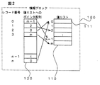
上記高速な検索、集計、ソート、ジョイン、更新等を実現するためには、与えられた表形式のデータを、所定の形式に変換する処理(以下、これを「コンパイル」ないし「コンパイル処理」と称する。)を実行する必要がある。この形式においては、図2に示すように、ある項目に関して、項目値が重複無くかつ所定の順序にて配置された値リストと、レコード番号に対応して要素が設けられ、各々の要素が、レコード番号に対応した項目値の配置された、値リスト中の位置を指定する配列(ポインタ配列)とが設けられている。このようなある項目に対して所定の形式となっているデータ群を情報ブロックと称する。
【0004】
コンパイル処理は、以下のような場合に必要となる。
(1)新規に与えられた表形式のデータを所定の形式に変換して記憶すべき場合、
(2)1または複数の項目から新たな項目を算出する場合、および、
(3)ある表形式のデータに、他の表形式のデータを追加すべき場合、たとえば、1月分の表に、2月分の表を追加する場合。
このように、コンパイル処理を実行すべき場合には、従来、既知のソート手法(たとえば、クイックソート)を用いて、値リスト中の項目値を並べ替えるなどの処理を実行していた。
【0005】
【発明が解決しようとする課題】
しかしながら、上記既知のソート方法を用いて情報ブロックを作成する場合には、以下の問題が生じる。
(1)一般に、O(n・log(n))の比較演算が必要とされ、多大な処理時間を要する。
(2)特にクイックソートを用いた場合に、データの分布により極端に処理効率が悪化する場合がある。
(3)複数のプロセッサを利用してソートを高速化することが困難である。
本発明は、高速な処理時間と、データの分布によっても処理効率が極端に悪化しないことが予測できるデータのコンパイル方法を提供することを目的とする。
また、本発明は、シングルプロセッサでも効果的であるが、特に、末子部パラレルシステムにおいてパフォーマンスを劇的に改善できるデータのコンパイル方法を提供することを目的とする。
【0006】
【課題を解決するための手段】
本発明の目的は、各々が、項目とこれに含まれる項目値とを含むレコードの配列として表わされる表形式データを、項目値が所定の順序でかつ重複なしに配置された値リストと、レコード番号に対応して、前記値リスト中の項目値を特定するための位置指定番号を収容した位置指定配列とを有する情報ブロックの形態に変換するデータのコンパイル方法であって、
前記表形式データにおいて、レコード番号と対応つけられた項目値からなる項目値配列と、項目値配列中の項目値の位置を特定する順位指定配列と、順位指定配列中の要素を特定する位置指定配列とからなる部分中間ブロックであって、初期的には、単一のレコードと対応つけられた部分中間ブロックを生成するステップと、
隣接する部分中間ブロックを選択して、第1の部分中間ブロックおよび第2の部分空間ブロックからなる対を生成するステップと、
前記対に関して、項目値配列を併合して新たな項目値配列を生成するステップと、
前記対に関して、第1の部分中間ブロックに属する項目値と第2の部分中間ブロックに属する項目値とを比較することで、併合された新たな項目値配列において、所定の順序にて項目値を特定するように、順位指定配列の要素を決定するステップと、
前記順位指定配列の要素の決定に伴って、併合前の項目値を特定できるように、前記位置指定配列の要素を決定するステップと、
隣接する部分中間ブロックを選択して対を生成し、併合した項目値配列、要素が決定された順位指定配列および位置指定配列からなる新たな部分中間ブロックを作成することを繰り返して、最終的に一つの部分中間ブロックを作成するステップとを備え、
前記最終的に作成された部分中間ブロックを情報ブロックとし、かつ、前記順位指定配列および項目値配列により値リストを構成することを特徴とするデータのコンパイル方法により達成される。
【0007】
本発明においては、部分中間ブロックの対を生成して、各部分中間ブロックの項目値の比較を行なうことで、対における項目値の順位を決定している。また、順次隣接する部分中間ブロックを対にして新たな部分中間ブロックを生成するような、いわゆるトーナメントの形態で、より大きな部分中間ブロックを生成している。本発明においては、「n」個のレコードに対して全ての項目値が異なっている場合には、比較の回数が、約「n*(log2(n)−1)」となり、いわゆるO(n・log(n))となる。しかしながら、「m(n>m)」個の項目値のみが異なり、これが「n」と比較して十分に小さい場合には、比較の回数は略「n」回にまで減じることができる。また、「m」が比較的大きな場合であっても、比較回数を「m*(log2(n)−1)」とすることができる。すなわち、処理効率を予測することができ、かつ、処理効率が最悪の場合でも、せいぜい、O(n・log(n))とすることが可能となる。
【0008】
また、いわゆるトーナメントの形態を利用しているため、部分中間ブロックの対の比較を、複数のプロセッサにてパラレル処理することに適している。これにより、処理時間を著しく減じることが可能となる。
【0009】
本発明の好ましい実施態様においては、順位指定配列の要素を決定するステップが、新たな順位指定配列を生成するステップと、第1の部分中間ブロックの項目値と第2の部分中間ブロックの項目値とを比較して、より高位の順位となるものを決定し、前記新たな順位指定配列の上位から順次、当該項目値を指定する第1の部分中間ブロック或いは第2の部分中間ブロック中の順位指定配列の値を配置するステップとを有し、
位置指定配列の要素を決定するステップが、前記新たな順位指定配列を特定するための位置指定再定義配列を生成するステップと、前記順位指定配列の値が配置される際に、第1の部分中間ブロック或いは第2の部分中間ブロックにおいて、位置指定再定義配列中の対応する位置に、前記新たな順位指定配列にて配置された値を特定できるような要素を配置するステップとを有し、
さらに、前記位置指定再定義配列にて、前記位置指定配列の値を変換して、新たな位置指定配列を求めるステップを備えている。
【0010】
本発明において、情報ブロックの値リストは、順位指定配列と項目値配列の形態となっていても良い。或いは、他の形態においては、さらに、最終的に一つの部分中間ブロックが生成された後に、前記順位指定配列中の上位に位置している要素にて特定される項目値を、順次配置することにより、重複なくかつ所定の順序にて配置された新たな項目値配列を作成するように構成しても良い。
また、本発明の目的は、上記ステップを備えたプログラムを記憶した、コンピュータにより読み取り可能な記憶媒体によっても達成される。
【0011】
【発明の実施の形態】
以下、添付図面を参照して、本発明の実施の形態につき説明を加える。図1は、本発明の実施の形態にかかる検索、集計およびサーチ方法を実現できるコンピュータシステムのハードウェア構成を示すブロックダイヤグラムである。図1に示すように、このコンピュータシステム10は、通常のものと同様の構成であり、プログラムを実行することにより、システム全体および個々の構成部分を制御するCPU12、ワークデータなどを記憶するRAM(Random Access Memory)14、プログラム等を記憶するROM(Read Only Memory)16、ハードディスク等の固定記憶媒体18、CD−ROM19をアクセスするためのCD−ROMドライバ20、CD−ROMドライバ20や外部ネットワーク(図示せず)と接続された外部端子との間に設けられたインタフェース(I/F)22、キーボードやマウスからなる入力装置24、CRT表示装置26を備えている。CPU12、RAM14、ROM16、外部記憶媒体18、I/F22、入力装置24および表示装置26は、バス28を介して相互に接続されている。
【0012】
本実施の形態にかかる、任意の表形式データをコンパイルするプログラム、コンパイルした表形式データから所定の項目の表(ビュー)を作成するプログラム、検索プログラム、集計プログラムおよびソートプログラムは、CD−ROM19に収容され、CD−ROMドライバ20に読取られても良いし、ROM16に予め記憶されていても良い。また、いったんCD−ROM19から読み出したものを、外部記憶媒体18の所定の領域に記憶しておいても良い。或いは、上記プログラムは、ネットワーク(図示せず)、外部端子およびI/F22を経て外部から供給されるものであっても良い。
本発明においては、任意の表形式データをコンパイルして、高速な検索、集計およびソートが可能な情報ブロックの集合体の形式を有するデータを構築する。
このデータを構築する際の高速なコンパイル方法が本発明の本質的事項となる。
【0013】
本発明者は、情報ブロックの集合体の形式を有するデータを利用した検索、集計およびソート方法を考案した(特願平10−227278号)。また、上記形式を有するデータを利用したデータのジョイン方法およびデータの削除/追加/更新方法を考案した(特願平11−151156号、特願平11−215450号)。まず、これら情報ブロックの構造、および、これを利用した検索について説明し、その後、上記情報ブロックの作成(コンパイル)につき説明を加える。
【0014】
図2は、本実施の形態にて用いる情報ブロックを示す図である。図2に示すように、情報ブロック100は、値リスト110と値リストへのポインタ配列120とを含んでいる。値リスト110は、表形式データの各項目に対して、その項目に属する項目値が順序付け(整数化)された項目値番号の順番に、上記項目値番号に対応した項目値111が格納されたテーブルである。値リストへのポインタ配列120は、表形式データのある列(すなわち項目)の項目値番号、つまり値リスト110へのポインタが表形式データのレコード番号順に格納された配列である。
【0015】
上記値リストへのポインタ配列120と値リスト110とを組み合わせることにより、あるレコード番号が与えられたときに、所定の項目に関する値リストへのポインタ配列120からそのレコード番号に対応して格納された項目値番号を取り出し、次いで、値リスト110内でその項目値番号に対応して格納された項目値を取り出すことにより、レコード番号から項目値を得ることができる。したがって、従来のデータ表と同様に、レコード番号(行)と項目(列)という座標を用いてすべてのデータ(項目値)を参照することができる。
【0016】
たとえば、図3(a)に示す表形式データを考える。この例では、顧客ID、顧客名、電話番号という項目に種々の項目値が与えられている。本実施の形態においては、このような表形式データを、図3(b)ないし(d)に示す形式の情報ブロックとして保持している。たとえば、図3(b)において、ポインタ配列120−1は、顧客IDを示す項目値を格納した値リスト110−1に関連付けられている。すなわち、先頭レコード(レコード番号「0」)のポインタ配列のポインタ値は0であり、これに対応して、顧客IDを示す項目値「1」が得られる。図3(b)において、ポインタ配列120−2は、顧客名を示す項目値を格納した値リスト110−2に関連付けられている。たとえば先頭レコード(レコード番号「0」)のポインタ配列におけるポインタ値は「5」であり、これに対応して、顧客名を示す項目値「山田 ○男」が得られる。図3(c)においても、同様に、ポインタ配列120−3が、電話番号を示す項目値を格納した値リスト110−3に関連付けられていることが理解できよう。また、各値リストにおいては、項目値が順序付けられて(この例では昇順)いることが理解できよう。
【0017】
さらに、本実施の形態においては、情報ブロック100の値管理テーブルは、値リスト110のほか、検索や集計のために用いる分類番号フラグ配列、項目値に対応するポインタを格納すべきメモリ空間の先頭アドレスを示す開始位置配列、および、存在数配列が含まれている。分類番号フラグ配列の各フラグ、および、存在数配列の各存在数は、項目値の各々に対応付けられている。分類番号フラグのフラグ値は、通常 「0」であり、検索や集計の際に見出すべき項目値に対応して「1」にセットされる。また、存在数は、その項目値を有するレコードの個数に対応する。なお、開始位置は、対応するポインタ値よりも小さなポインタ値に対応する存在数を加算したものに対応するため、必ずしも設ける必要はない。
図4(a)は、表形式データの他の例を示す図、図4(b)および(c)は、それぞれ、「性別」および「年令」に関する情報ブロックを示す図である。図4(b)に示すように、性別に関する情報ブロック200−1の値管理テーブル210−1には、ポインタ配列220の各ポインタ値に対応する項目値(「男性」および「女性」)と、各項目値に対応する分類番号、開始位置および存在数が示されている。たとえば、ポインタ値が「0」(つまり、値リストの項目値が「男性」)であるようなレコードの数は632564個であり、その一方、ポインタ値が「1」(つまり、値リストの項目値が「女性」)であるようなレコードの数は367426個となっている。また、各項目値に対応する開始位置は、後述するレコードへのポインタ配列230−1の先頭アドレスを示している。図4(c)においても、同様のことが理解できよう。
【0018】
このようなデータ構造を有する情報ブロックを用いた検索の一例につき以下に説明を加える。図5は、単一項目に関する検索手法を示すフローチャートである。この処理は、CPU12(図1参照)が所定の検索プログラムを実行することにより実現される。この例では、「年令」の項目値が16歳または19歳であるレコードが検索される。まず、表形式データに関する情報ブロックのうち、図4(c)に示す「年令」に関する情報ブロック200−2が特定される(ステップ501)。
【0019】
次いで、特定された情報ブロック(以下、「特定情報ブロック」と称する。)の値リスト210−2において、項目値が上記検索条件に合致するもの(16歳または19歳)に対応する行の分類番号が「1」にセットされる(ステップ502)。本例の場合には、項目値番号「0」および項目値番号「3」に対応する行の分類番号が1にセットされる。次いで、分類番号が「1」にセットされている行に対応した開始位置および存在数が取得される(ステップ503)。これら情報をポインタ取り出し情報と称する。レコードへのポインタ配列において、ステップ503にて取得されたポインタ取り出し情報に基づき、検索条件に合致したレコードへのポインタを示すレコード番号が取り出される(ステップ504)。
本例においては、項目値番号「0」に対応したレコードのポインタは、レコードへのポインタ配列の開始位置「0」すなわち先頭から、45898個目までの領域に格納され、その一方、項目値番号「3」に対応したレコードのポインタは、レコードへのポインタ配列の2383137番目から189653個分の領域に格納されていることがわかる。最後に、後の処理にて利用できるようにするために、取り出されたレコード番号の配列が、結果集合として作成され、これが保持される(ステップ505)。
また、集計およびソートも、分類番号、開始位置および存在数を利用することにより実現することができる。
【0020】
次に、上記情報ブロックを生成するためのコンパイル処理について説明を加える。このコンパイル処理においては、ある項目について無作為に配置されたデータを、重複なくかつ所定の順序(たとえば五十音順やアルファベット順)でソートされた値リストを作り出している。図6(a)は、表形式データにおける、レコードとある項目(姓)の項目値とを示す図である。本実施の形態にかかるコンパイル処理においては、この図6(a)に示すような、項目値がランダムに並べられた項目に関して、図6(b)に示すような形式の情報ブロックを生成する。
図6(b)において、情報ブロック600には、値リストへのポインタ配列601(以下、「PV」と称する。)、および、値リスト602が含まれる。コンパイル処理の直後には、値リスト602は、元の項目値が収容された配列(オリジナル項目値配列)603と、当該オリジナル項目値配列603の格納位置番号を示す配列604(以下、「VLP」と称する。)とから構成される。上記ポインタ配列(PV)は、値リスト中の項目値を指定するという意味で、位置指定配列ということができる。また、VLPは、項目値の順序を表しているという意味で、順位指定配列ということができる。コンパイル処理の直後の情報ブロックは、上述した図3(b)に示す情報ブロックとは若干形式が異なっているが、後に述べる処理により同等の形式とすることができる。
図7は、この実施の形態にかかるコンパイル処理の概略を示すフローチャートである。図7に示すように、コンパイル処理においては、コンピュータシステム10は、固定記憶媒体18等に記憶された表形式データを読み出し(ステップ701)、情報ブロックを作成する必要がある項目を特定する(ステップ702)。たとえば、全ての項目について情報ブロックを作成しても良いし、指定された任意の項目に関する情報ブロックのみを作成しても良い。また、読み出した表形式データは、RAM14上に一時的に保存しておくのが、処理時間を考慮した場合に望ましい。
【0021】
次いで、コンピュータシステム10は、表形式データから所定の項目を選択して、当該項目にかかるデータ(項目値)をレコード番号と関連付けて切り出す(ステップ703)。これにより、たとえば、図6(a)に示す形式のデータを取り出すことができる。次いで、当該項目に関する情報ブロックが作成される(ステップ704)。この処理については後に詳述する。ステップ703、704の処理は、指定された全項目について実行される(ステップ705、706参照)。これにより、所定の項目に関する情報ブロックが完成する。
【0022】
次に、ステップ704の処理につきより詳細に説明を加える。ステップ704の処理は、隣接するレコードを順次組み合わせて、当該組み合わせにおいてPVやVLP中の値を決定することにより実現される。たとえば、レコード番号が0〜4n(レコード数=4n+1)である項目について、図8(a)に示すように、初期的には、4n+1個の部分中間ブロック801−0〜801−(4n)を考える。そして、隣接する二つの部分中間ブロック(たとえば、部分中間ブロック801−0と部分中間ブロック801−1)を組み合わせて、図8(b)に示す新たな部分中間ブロック(たとえば、部分中間ブロック811−0)を考え、これら新たな部分中間ブロックにおいてPVやVLPの値を更新する。図8(b)に示すように、この時点で、(2n+1)個の新たな部分中間ブロックが作られる。
さらに、隣接する二つの部分中間ブロック(たとえば、部分中間ブロック811−0と811−1)とを組み合わせて、図8(c)に示すように新たな部分中間ブロック(たとえば、部分中間ブロック821−0)を考え、これら新たな部分中間ブロックにおいてPVやVLPの値を更新する。
【0023】
このような処理を繰り返すことで、最終的には、2つの部分中間ブロックを組み合わせたブロックを作り出すことができる。このブロックが情報ブロックとなる。上記処理をフローチャートにて表したものを図9に示す。
図9のステップ901にて生成される初期的な部分中間ブロックには、たとえば、図8(a)の部分中間ブロックが対応する。また、末尾のブロックまで、隣接する部分中間ブロックが選ばれて(ステップ902)、これらが合併されて、変換配列(以下、「TR」と称する。)や合併後の新たな格納位置番号を示す配列(以下、「VLP’」と称する。)のための領域が確保される(ステップ903)。次いで、合併された形態のPVやVLPの値が更新される(ステップ904、905)。上記TRは、PVを再定義するために利用されるため、位置指定再定義配列ということができる。
【0024】
さらに、あるレベルの部分中間ブロック群において末尾の部分中間ブロックまで、合併の処理が終了すると、合併された部分中間ブロックの数が1つであるか否かが判断される(ステップ906)。ここで「イエス(Yes)」と判断されれば、当該1つの部分中間ブロックが完成した情報ブロックとなる。その一方、「ノー(No)」と判断されれば、合併後の複数の部分中間ブロックを、処理対象として再度ステップ902〜905の処理が進められる。
図6(a)に示すレコード番号と、「姓」という項目の対応する項目値とを例にとって、図9の処理、特にステップ902〜904の処理を詳細に説明する。
【0025】
まず、図17に示すように、9つの初期的な部分中間ブロックが生成される(図9のステップ901参照)。ここで、冒頭の部分中間ブロック1701−0および部分中間ブロック1701−1が合併され、PVやVLPが更新される(図9のステップ904参照)。
図10は、ステップ904の処理をより詳細に示す図である。この処理において、合併される二つの部分中間ブロックのうち、より小さなレコード番号に関するものを第1の部分中間ブロック、より大きなレコード番号に関するものを第2の部分中間ブロックと称する。また、第1の部分中間ブロックにおいて、比較対象となる項目値を示すために、VLPの値を指すように配置されたポインタを第1の比較位置ポインタと称し、第2の部分中間ブロックにおいて、比較対象となる項目値を示すために、VLPの値を指すように配置されたポインタを第2の比較位置ポインタと称する。この比較位置ポインタは、図10の処理の冒頭では、各部分中間ブロックにおいて最も小さいレコード番号を有するVLPの値を指している。さらに、この処理において生成されるVLP’において値を格納すべき位置を示すポインタを格納位置ポインタと称する。これら第1の比較位置ポインタ、第2の比較位置ポインタおよび格納位置ポインタは、図10の処理に先立って、初期位置(各VLPにおける先頭の位置)に設定される。
【0026】
図10に示すように、コンピュータシステム10は、第1の比較位置ポインタにて指示される項目値(第1の指示値)と、第2の比較位置ポインタにて指示される項目値(第2の指示値)とを取り出して、これらの値を比較する(ステップ1001〜1003)。以下、第1の指示値および第2の指示値の大小、或いは、第1の比較ポインタおよび第2の比較ポインタの位置により、異なる処理に進む(ステップ1004〜ステップ1014参照)。
図15に示す部分中間ブロック1501−0、1501−1に着目すると、初期的には、第1の比較位置ポインタは、部分中間ブロック1501−0における「たなか」を指示し、その一方、第2の比較位置ポインタは、部分中間ブロック1501−1における「あべ」を指示する。したがって、これらを比較すると(図10のステップ1003参照)、「第1の指示値>第2の指示値」となる(ステップ1008参照)。この場合には、ステップ1009に進み、図13に示す処理が実行される。
【0027】
より詳細には、第2の比較位置ポインタが示す項目値「あべ」と対応するVLPの値「1」が特定され(ステップ1301)、当該VLPの値「1」が、VLP’中の格納位置ポインタにて示される位置(先頭つまり格納位置番号「0」の位置)に格納される(ステップ1302)。次いで、第2の比較位置ポインタの位置に対応するTRの値として、格納位置ポインタの位置している格納位置番号(この場合には「0」)が与えられる(ステップ1303)。
その後に、コンピュータシステム10は、第2の比較位置ポインタを一つ下流側(格納位置番号が大きくなる側)に移動させる(ステップ1304)とともに、格納位置ポインタも一つ下流側に移動させる(ステップ1305)。
【0028】
このような処理の後、再度ステップ1001〜ステップ1003の処理が実行される。しかしながら、上記例では第2の比較位置ポインタを一つ下流側に移動させると、第2の比較位置ポインタが指し示す項目値が存在しない。このため、ここではステップ1012にてイエス(Yes)と判断され、図12の処理が実行される。
【0029】
より詳細には、第1の比較位置ポインタに示す項目値「たなか」と対応するVLPの値「0」が特定され(ステップ1201)、これが、VLP’中、格納位置ポインタが示す位置(2番目の位置つまり格納位置番号「1」にて示される位置)に格納される(ステップ1202)。次いで、第1の比較位置ポインタの位置に対応するTRの値として、格納位置ポインタの位置している格納位置番号(この場合には「1」)を与える(ステップ1203)。その後に、第2の比較位置ポインタを一つ下流側(格納位置番号が大きくなる側)に移動させる(ステップ1204)とともに、格納位置ポインタも一つ下流側に移動させる(ステップ1205)。
さらに、再度ステップ1001〜ステップ1003が実行されるが、第1の比較位置ポインタおよび第2の比較位置ポインタとも、指示する項目値が存在しない。このため、ここではステップ1004〜ステップ1012においてノー(No)と判断されてステップ1014に進む。
【0030】
より詳細には、第1の部分中間ブロック(図15の符号1501−0参照)において、PVの値を、それぞれ、対応するTRの値で変換して、新たなPVを生成する(ステップ1401)とともに、第2の部分中間ブロック(図15の符号1501−1参照)において、PVの値を、それぞれ、対応するTRの値で変換して、新たなPVを生成する(ステップ1402)。図16に、新たなPVやVLPの生成についてより具体的に説明する。たとえば、第1の部分中間ブロック1501−0中のPV(旧PV)1601の要素(値)「0」を取り出し、この要素にて示される格納位置番号のTR1602の要素(値)を特定する。この要素(値)は「1」であるため、新たなPV(新PV)1603において、当該TRの要素にて示される格納位置番号に示される位置に、旧PVの要素「0」を収容すればよい。第2の部分中間ブロックにおいても同様の処理が進められ、これにより、新PVを得ることが可能となる。
また、図10のステップ1001〜1013の処理を繰り返すことによって作り出されたVLP’が、新たなVLPとなる(ステップ1403、図16の符号1604参照)。
【0031】
他の部分中間ブロックの組でも図10の処理が実行されて、新PVおよび新VLPが作り出される。図10〜図14の処理においてまだ説明していないものを中心に、他の部分中間ブロックの組に関する処理につき説明する。図15に示す部分中間ブロック1501−4、1501−5に着目すると、初期的には、第1の比較位置ポインタは、部分中間ブロック1501−4における「あべ」を指示し、その一方、第2の比較位置ポインタは、部分中間ブロック1501−5における「たなか」を指示する。したがって、これらを比較すると、「第1の指示値<第2の指示値」となり(ステップ1006でイエス(Yes))、ステップ1007に進み、図12の処理が実行される。
【0032】
図12においては、第1の比較位置ポインタが示す項目値「あべ」と対応するVLPの値「4」が特定され(ステップ1201)、当該VLPの値「4」が、VLP’中の格納位置ポインタにて示される位置(格納位置番号「4」の位置)に格納される(ステップ1202)。次いで、第1の比較位置ポインタの位置に対応するTRの値として、格納位置ポインタの位置している格納位置番号(この場合には「4」)が与えられる(ステップ1203)。
その後に、コンピュータシステム10は、第1の比較位置ポインタを一つ下流側(格納位置番号が大きくなる側)に移動させる(ステップ1204)とともに、格納位置ポインタも一つ下流側に移動させる(ステップ1205)。
【0033】
このような処理の後、再度ステップ1001〜ステップ1003の処理が実行される。しかしながら、この例では第1の比較位置ポインタを一つ下流側に移動させると、第1の比較位置ポインタが指し示す項目値が存在しない。このため、ここでは、ステップ1010にてイエス(Yes)と判断され、図13に示す処理に進む。
【0034】
図13の処理では、第2の比較位置ポインタが示す項目値「たなか」と対応するVLPの値「5」が特定され、これが、VLP’中、格納位置番号「5」にて示される位置に格納される(ステップ1301、1302)。また、第2の比較位置ポインタに対応するTRの値として、格納位置番号「5」が与えられる(ステップ1303)。次いで、第2の比較位置ポインタおよび格納位置ポインタが一つ下流側に移動される(ステップ1304、1305)。
この時点で、第1の比較位置ポインタおよび第2の比較位置ポインタの双方とも、指示する項目値が存在しないため、ステップ1014に進み、新PVおよび新VLPが作り出される(ステップ1401〜1403参照)。
【0035】
次に、図15に示す部分中間ブロック1501−6、1501−7に着目すると、初期的には、第1の比較位置ポインタは、部分中間ブロック1501−7における「いとう」を指示し、その一方、第2の比較位置ポインタは、部分中間ブロック1501−7における「いとう」を指示する。したがって、これらを比較すると、「第1の指示値=第2の指示値」となり(ステップ1004でイエス(Yes))、ステップ1005に進む。
図11においては、第1の比較位置ポインタが示す項目値「いとう」と対応するVLPの値「6」が特定され(ステップ1101)、当該VLPの値「6」が、VLP’中の格納位置ポインタにて示される位置(格納位置番号「6」の位置)に格納される(ステップ1102)。次いで、第1の比較位置ポインタに対応するTRの値として、格納位置ポインタの位置している格納位置番号「6」が与えられる(ステップ1103)。その後に、第1の比較位置ポインタが一つ下流側に移動される。
【0036】
同様に、第2の比較位置ポインタの位置に対応するTRの値として、格納位置ポインタが位置している格納位置番号「6」が与えられ(ステップ1105)、第2の比較位置ポインタが一つ下流側に移動される(ステップ1106)。
このように、双方の部分中間ブロックにおいて、同じ項目値が存在する場合には、その重複を排除する形で、VLP’に値が収容される。
その後の処理では、第1の比較位置ポインタ、第2の比較位置ポインタとも、指示する項目値が存在しないため、図14に進み、新PVおよび新VLPが作られる。
【0037】
このようにして、図15の符号1511−0〜1511−4に示すような新たな部分中間ブロックを得ることができる。これら部分中間ブロックについて、図9〜図14の処理が実行される。ここでは、図17に示すように、部分中間ブロック1511−0をそのままにして、部分中間ブロック1511−1、1511−2の組、部分中間ブロック1511−3、1511−4の組を作り、部分中間ブロックの組のそれぞれに関する処理を実行している。
部分中間ブロック1511−1、1511−2の組に関する処理について、再度、フローチャート等を参照して説明を加える。図18(a)の矢印A、BおよびCに示すように、初期的には、第1の比較位置ポインタ、第2の比較位置ポインタおよび第3の比較位置ポインタは、それぞれ、VLP、VLP’の先頭に配置される。
【0038】
図10にしたがって、第1の比較位置ポインタ(図18(a)の矢印A)が指し示すVLPの値「3」にて特定される項目値「いとう」が取り出され(ステップ1011参照)、その一方、第2の比較位置ポインタ(同図の矢印B)が指し示すVLPの値「4」にて特定される項目値「あべ」が取り出される(ステップ1012)。
第1の指示値「いとう」と第2の指示値「あべ」とを比較すると、第1の指示値>第2の指示値となるため(ステップ1008でイエス(Yes))、図13の処理が実行される。これにより、図18(b)に示すように、格納位置ポインタ(矢印C)にて示される位置に、VLPの値「4」が配置されるとともに、所定のTR中の値も配置される。その後に、第2の比較位置ポインタおよび格納位置ポインタが、一つ下流側に移動される(矢印B’および矢印C’)参照。
【0039】
次いで、第1の比較位置ポインタ(図18(b)の矢印A)が指し示すVLPの値「3」にて特定される項目値「いとう」と、第2の比較位置ポインタ(同図の矢印B’)が指し示すVLPの値「5」にて特定される項目値「たなか」とが比較される(図10のステップ1001〜1003)。この場合には、第1の指示値<第2の指示値となるため、ステップ1007に進み、図18(c)に示すように、格納位置ポインタ(同図矢印C)にて示される位置に、第1の比較位置ポインタにて示されるVLPの値「3」が配置されるとともに、所定のTRの値も配置される。また、第1の比較位置ポインタおよび格納位置ポインタが一つ下流側に移動される(矢印A’および矢印C’参照)。
【0040】
さらに、第1の比較位置ポインタ(図18(c)の矢印A’)が指し示すVLPの値「2」にて特定される項目値「たなか」と、第2の比較位置ポインタ(同図の矢印B)が指し示すVLPの値「5」にて特定される項目値「たなか」とが比較される(図10のステップ1001〜1003参照)。この場合には、第1の指示値=第2の指示値となるため、ステップ1005に進む。ここでは、図18(d)に示すように、格納位置ポインタ(矢印C)にて示される位置に、第1の比較位置ポインタにて示されるVLPの値「2」が配置される。また、第1の比較位置ポインタおよび第2の比較位置ポインタにて示される位置に対応するTRの値として、格納位置ポインタが指し示す格納位置番号「4」が配置される。
【0041】
このような処理の後、再度図10の処理が進められると、ステップ1014に進む。ここでは、旧PVをTRにて変換して新たなPVを作る処理が実行される。旧PVの値が取りだされ、当該値が指し示す位置のTRの値を特定して、当該TRの値を、新PVにおいて前記旧PVを取り出した値の位置と対応する位置に配置する。この処理を繰り返すことで、図20(b)に示すような新PV2001を得ることが可能となる。
【0042】
次に、部分中間ブロック1511−3、1511−4からなる組に関する処理についても簡単に説明する。ここでも、先の部分中間ブロックの組と同様の処理が進められる。たとえば、最初に図10の処理を施すことにより、図19(b)に示すように、格納位置ポインタ(図19(b)の矢印C)の位置に、第2の格納位置ポインタ(同図の矢印B)にて指し示されるVLPの値「8」が配置されるとともに、対応するTRの値「6」が決定される。また、次に図10の処理を施すことにより、図19(c)に示すように、格納位置ポインタ(図19(c)の矢印C)の位置に、第1の比較位置ポインタ(図19(c)の矢印A)にて指し示されるVLPの値「6」が配置されるとともに、所定のTRの値(第1の比較位置ポインタおよび第2の比較位置ポインタが指し示す位置に対応するTRの値)が決定される。
【0043】
最後に、もう一度図10の処理を施すことにより、ステップ1014において新たなPVが作られる(図20(b)参照)。
これにより、図17の符号1701−1、1701−2に示すような部分中間ブロックを作り出すことができる。
【0044】
さらに、この例では、部分中間ブロック1701−0(実際には、部分中間ブロック1501−0と同じ)と部分中間ブロック1701−1とを併合している。ここでも、図10に示す処理が繰り返され、部分中間ブロック1701−0と部分中間ブロック1701−1との間で、比較位置ポインタにて指し示すVLPの値により特定される項目値の比較結果にしたがって、VLP’の値やTRの値が順次決定される。
【0045】
図21に示すように、部分中間ブロック1701−0と部分中間ブロック1701−1に関して、図10の処理が施される。図21(a)に示すように、最初に実行される図10の処理では、第1の比較位置ポインタ(図21(a)の矢印A)が示すVLPの値「1」にて特定される項目値「あべ」と、第2の比較位置ポインタ(図21(b)の矢印B)が示すVLPの値「4」にて特定される項目値「あべ」とが比較される。この比較結果に基づき図11(ステップ1005)の処理が実行されて、格納位置ポインタ(図21(a)の矢印C)に示すVLP’中の値「1」が決定されるとともに、第1および第2の比較位置ポインタの位置に対応するTR中の値「0」が決定される。
【0046】
また、図21(b)に示すように、次に実行される図10の処理では、第1の比較位置ポインタ(図21(b)の矢印A)が示すVLPの値「0」にて特定される項目値「たなか」と、第2の比較位置ポインタ(図21(b)の矢印B)が示すVLPの値「3」にて特定される項目値「いとう」とが比較される。この比較結果に基づき、図13の処理(ステップ1009)が実行されて、格納位置ポインタ(図21(b)の矢印C)に示すVLP’中の値「3」が決定されるとともに、第2の比較位置ポインタの位置に対応するTR中の値「1」が決定される。
【0047】
さらに、図21(c)に示すように、次に実行される図10の処理では、第1の比較位置ポインタ(図21(c)の矢印A)が示すVLPの値「0」にて特定される項目値「たなか」と、第2の比較位置ポインタ(図21(c)の矢印B)が示すVLPの値「2」にて特定される項目値「たなか」とが比較される。この比較結果に基づき、図11の処理(ステップ1005)が実行されて、格納位置ポインタ(図21(c)の矢印C)に示すVLP’の値「0」が決定されるとともに、第1および第2の比較位置ポインタの位置に対応するTR中の値「2」が決定される。この後に実行される図10の処理では、第1の比較位置ポインタおよび第2の比較位置ポインタが示すVLPの値が存在しないため、図14の処理(ステップ1014)が実行され、PV(旧PV)の値が、関連するTRにて変換されて、新たなPV(新PV)を得ることができる(図23(a)参照)。
このような処理により、図17の符号1711−0にて示すような部分中間ブロックが生成される。最後に、部分中間ブロック1711−0と部分中間ブロック1711−1(実際には部分中間ブロック1701−2と同じ)との組を作り、この部分中間ブロックの組について所定の処理を実行する。
【0048】
上記部分中間ブロック1711−0、1711−1の組に関する処理について、フローチャート等を参照して説明を加える。たとえば、最初に図10の処理においては、図22(a)に示すように、第1の比較位置ポインタ(図22(a)の矢印A)が示すVLPの値「1」にて特定される項目値「あべ」と、第2の比較位置ポインタ(図22(b)の矢印B)が示すVLPの値「8」にて特定される項目値「あべ」とが比較される。この比較結果に基づき図11(ステップ1005)の処理が実行されて、格納位置ポインタ(図22(a)の矢印C)に示すVLP’中の値「1」が決定されるとともに、第1および第2の比較位置ポインタの位置に対応するTR中の値「0」が決定される。
【0049】
また、図22(b)に示すように、次に実行される図10の処理では、第1の比較位置ポインタ(図22(b)の矢印A)が示すVLPの値「3」にて特定される項目値「いとう」と、第2の比較位置ポインタ(図22(b)の矢印B)が示すVLPの値「3」にて特定される項目値「いとう」とが比較される。この比較結果に基づき、図11の処理(ステップ1005)が実行されて、格納位置ポインタ(図22(b)の矢印C)に示すVLP’中の値「3」が決定されるとともに、第1および第2の比較位置ポインタの位置に対応するTRの値「1」が決定される。
【0050】
さらに、図22(c)に示すように、次に実行される図10の処理では、第1の比較位置ポインタ(図22(c)の矢印A)が示すVLPの値「0」は存在するが、第2の比較位置ポインタ(図22(c)の矢印B)が示すVLPの値が存在しないため、図12の処理(ステップ1013)に進み、格納位置ポインタ(図22(c)の矢印C)に示すVLP’の値「0」が決定されるとともに、第1の比較位置ポインタの位置に対応するTR中の値「2」が決定される。この後に実行される図10の処理では、第1の比較位置ポインタおよび第2の比較位置ポインタが示すVLPの値が存在しないため、図14の処理(ステップ1014)が実行され、PV(旧PV)の値が、関連するTRにて変換されて、新たなPV(新PV)を得ることができる(図23(b)参照)。
【0051】
このようにして、図6(b)に示すように、VP601と、VLP604およびオリジナル項目値配列603からなる値リスト602を有する情報ブロック600を得ることができる。ここで、オリジナル項目値配列においては、実際には、格納位置番号「0」、「1」および「3」に対応する要素(項目値)「たなか」、「あべ」および「いとう」(符号610、611、613参照)のみが利用され、他の要素(項目値)(たとえば、符号612、614参照)が利用されていない、つまり、VLPの値に指し示されていないことが理解できる。すなわち、オリジナル項目値配列において、項目値が重複している場合には、もっとも格納位置番号の小さなもののみが利用され、他のものは利用されない。
【0052】
この形式であっても、図3(b)に示す情報ブロックと同等であることにつき以下に説明を加える。たとえば、図6(a)においては、レコード番号「0」に対応して項目値「たなか」が特定されている。図6(b)においても、レコード番号「0」に対応して、PV中、格納位置番号「0」の要素(値)「2」が特定される。この要素「2」を格納位置番号とするように、VLP中の要素(値)を特定すると、「0」を得ることができ、さらに、当該VLPの要素(値)「0」を格納位置番号とするオリジナル項目値配列の項目値「たなか」を特定することが可能となる。他のレコード番号についても同様に、項目値を得られることは明らかである。
【0053】
したがって、図6(b)に示すVLP604およびオリジナル項目値配列603からなる値リスト602を利用して、検索、集計およびソートを実現することも可能である。ただし、この場合には、オリジナル項目値配列をそのまま利用することになる。図6(b)から明らかなように、オリジナル項目値配列においては、項目値が重複する場合には、格納位置番号が最も小さいもののみが利用され、残りの項目値が利用されない。したがって、重複が多い場合には、オリジナル項目値配列において利用されない部分が多く出現する。そこで、VLPの値にて示す項目値を、新たな配列に収容することで、重複のまったくない項目値配列(圧縮型値リスト)を作成することが可能となる。
【0054】
図24は、圧縮型値リストを生成する処理を示すフローチャートである。図24に示すように、コンピュータシステム10は、格納位置番号を初期化するとともに、圧縮型値リストのための領域を確保する(ステップ2401)。この領域に配置されるデータ(項目値)のレコード数は、VLPに含まれる値の数と対応するため、この値の数に対応して領域を確保すればよい。
【0055】
次いで、格納位置番号が示すVLP中の値が取り出され(ステップ2402)、当該VLPの値が示す、オリジナル項目値配列中の項目値が特定される(ステップ2403)。その後に、特定された項目値が、圧縮型値リスト中、格納位置番号が示す位置に配置される(ステップ2404)。この処理は、全てのVLPの値に関して実行される(ステップ2405、2406参照)。たとえば、図6(b)に示す値リスト602に関して、図24の処理を施すと、図25(a)に示すように、VLPの値(たとえば、格納位置番号「0」にて示される値「1」)によりオリジナル項目値配列中の項目値(たとえば「あべ」)が特定され(ステップ2402、2403)る。そして、この項目値が、圧縮型値リストの格納位置番号にて示される位置(たとえば「0」の位置)に配置される。
【0056】
このような処理の結果、図6(b)に示す情報ブロック600は、図25(b)に示すように、PV601と圧縮型値リスト2501とを有する情報ブロック2500に変換される。新たなに得られた情報ブロック2500は、図3(b)に示す情報ブロックと同じ形式であることが理解できるであろう。図24の処理の結果得られた情報ブロック2500に基づき、検索、集計およびソートの処理を実行できることは言うまでもない。
【0057】
上記コンパイル処理において、図10に示す処理を繰り返して二つの部分中間ブロックを併合することにより得られた配列につき再度考察を加える。たとえば、図18(d)のVLP’および項目値配列を参照する。新たなVLP(新VLP)であるVLP’(符号1801参照)中、格納位置番号「2」の位置に収容された値「4」にて特定される、項目値配列(符号1802参照)の要素(値)は、「あべ」である。また、新VLP1801中、格納位置番号「3」の位置に収容あれた値「3」にて特定される、項目値配列1802の要素(値)は「いとう」である。さらに、新VLP1801中、格納位置番号「4」の位置に収容あれた値「2」にて特定される、項目値配列1802の要素(値)は「たなか」である。新VLPおよび項目値配列により、併合された部分中間ブロックに関する、項目値がソートされた状態の値リストが作られていることが理解できる。すなわち、ある二つの部分中間ブロックに関して図10の処理を繰り返し実行することにより、上記二つの部分中間ブロックを併合した部分中間ブロックに関して、項目値が所定の順序で並べられかつ重複が排除された値リストが作られる。
【0058】
上記構成のデータのコンパイル方法における処理速度について考察を加える。
ここでは説明を容易にするために、値リストを、VLPおよび項目値配列の形式ではなく、VLPの値により項目値配列の値を特定し、これを並べた配列(圧縮型値リスト)の形式として説明する。
図26に示すように、8つのレコードに、0〜7の何れかの数字が項目値として割り当てられていると考える。ここで、各レコードに対応する項目値は全てことなると考える。この場合に、本実施の形態においては、レコード番号が「0」および「1」の値リスト(符号2601−0、2601−1参照)に関する部分中間ブロックの組、レコード番号「2」および「3」の値リストに関する部分中間ブロックの組など、4つの部分中間ブロックの組(図26(b)参照)のそれぞれに関して図10の処理が繰り返し実行される。
【0059】
上記例では全ての項目値が異なるため、4回の項目値の比較、すなわち、「2」と「6」との比較、「4」と「0」との比較、「3」と「7」との比較および「5」と「1」との比較が行なわれる。これを一般化すると、要素が「n(ただしnは2の累乗であるのが望ましい)」であれば、最初の処理においては、「n/21」回の比較が実行されることになる。
【0060】
次の部分中間ブロックの併合により4つの部分中間ブロックから、2つの部分中間ブロックが作られる(図26(b)および(c)参照)。ここでは、部分中間ブロック2602−0、2602−1に関して、3回の項目値の比較、つまり、「2」と「0」との比較、「2」と「4」との比較、および、「6」と「4」との比較が実行され、残りの情報ブロックに関しても、3回の項目値の比較、つまり、「3」と「1」との比較、「3」と「5」との比較、および、「7」と「5」との比較が実行される。これを一般化すると、要素が「n(ただしnは2の累乗であるのが望ましい)」であれば、最大で「(n/22)*(22−1)」回の比較が実行されることになる。
さらに、2つの部分中間ブロックから最終的な情報ブロックが作られる(図26(c)および(d)参照)。ここでは、7回の項目値の比較、つまり、「0」と「1」、「2」と「1」、「2」と「3」、「4」と「3」、「4」と「5」、「6」と「5」、および、「6」と「7」の比較が実行される。これを一般化すると、要素が「n(ただしnは2の累乗であるのが望ましい)」であれば、最大で「(n/23)*(23−1)」回の比較が実行されることになる。
【0061】
上記比較回数を検討すると、部分中間ブロックの併合において以下の回数だけ比較処理が実行される。
1回目 :(n/21)回
2回目 :(n/22)*(22−1)回
3回目 :(n/23)*(23−1)回
:
log2(n)回目 :(n/2log2(n))*(2log2(n)−1)回
【0062】
情報ブロック生成に必要な比較回数は、上記各併合処理における比較回数の総和と考えられる。したがって、
総比較回数は、以下の式1により得ることが可能である。
【数1】

【0063】
これに対して、「n」個の項目値のうち、「m」個が異なる場合を考える。この場合には、部分中間ブロックの併合において以下の回数だけ比較処理が実行される。
1回目 :(n/21)回
2回目 :(n/22)回
3回目 :(n/23)回
:
log2(n)回目 :(n/2log2(n))回
と考えることができるため、総比較回数は約「n」回と考えることができる。
【0064】
その一方、「n」が「m」に対して比較的大きい場合には、
1回目 :(n/21)回
2回目 :(n/22)*((m/n)*22−1)回
3回目 :(n/23)*((m/n)*23−1)回
:
log2(n)回目 :(n/2log2(n))*((m/n)*2log2(n)−1)回
と考えることができるため、総比較回数は、以下の式2となる。
【数2】
このように、「n」個の項目値中、「m」個が異なる場合には、「m」の大きさにしたがって以下のように比較処理が実行される。
「m」が十分に小さい場合:約「n」回の比較
「m」が比較的大きい場合:約「m*log2(n)−1」回の比較
したがって、特に項目値の重複が大きい場合には、ほぼ「n」のオーダーで情報ブロックを生成することが可能となる。
【0066】
本実施の形態によれば、部分中間ブロックの対からなる新たな部分中間るブロックを作成して、この新たな部分空間ブロックにおける項目値の比較によって、部分中間ブロックにおける項目値配列を作成し、部分中間ブロックを漸次大きくすることにより、最終的に一つの部分中間ブロックを得て、これを情報ブロックとしている。したがって、対に関する処理を、複数のプロセッサによりパラレルに実施することが可能となる。
【0067】
本発明は、以上の実施の形態に限定されることなく、特許請求の範囲に記載された発明の範囲内で、種々の変更が可能であり、それらも本発明の範囲内に包含されるものであることは言うまでもない。
前記実施の形態にかかる部分中間ブロックの対に対する処理は、シングルプロセッサにより実行されても良いし、パラレルプロセッサを有するシステムにおいて、ある対の処理をあるプロセッサに割り当てることにより、より高速化を図っても良いことは言うまでもない。
【0068】
また、部分中間ブロックの対の選択は、前記実施の形態に示すものに限定されず、隣接する二つの部分中間ブロックであれば所望のように、対とすることが可能である。
さらに、前記実施の形態においては、一般のコンピュータシステム10内に、所定のプログラムを読み込み、当該プログラムを実行することにより、複数の表形式データのジョインおよびジョインされた表形式データに関する処理を実現しているが、本発明はこれに限定されるものではなく、パーソナルコンピュータ等のような一般のコンピュータシステムに、データベース処理専用のボードコンピュータを接続し、当該ボードコンピュータが上記処理を実行できるように構成しても良いことは言うまでもない。したがって、本明細書において、手段とは必ずしも物理的手段を意味するものではなく、各手段の機能が、ソフトウェアによって実現される場合も包含する。さらに、一つの手段の機能が、二つ以上の物理的手段により実現されても、若しくは、二つ以上の手段の機能が、一つの物理的手段により実現されてもよい。
【0069】
【発明の効果】
本発明によれば、高速な処理時間と、データの分布によっても処理効率が極端に悪化しないことが予測できるデータのコンパイル方法を提供することが可能となる。
また、本発明によれば、特に、末子部パラレルシステムにおいてパフォーマンスを劇的に改善できるデータのコンパイル方法を提供することが可能となる。
【図面の簡単な説明】
【図1】 図1は、本発明の実施の形態にかかる検索、集計およびサーチ方法を実現できるコンピュータシステムのハードウェア構成を示すブロックダイヤグラムである。
【図2】 図2は、本実施の形態にて用いる情報ブロックを示す図である。
【図3】 図3は、表形式データの例、および、当該表形式データに基づく情報ブロックの例を示す図である。
【図4】 図4は、表形式データの他の例、および、当該表形式データに基づく情報ブロックの他の例を示す図である。
【図5】 図5は、単一項目に関する検索手法を示すフローチャートである。
【図6】 図6は、ある項目に関するレコード番号と項目値との関係、および、完成した本実施の形態にかかる情報ブロックを示す図である。
【図7】 図7は、本実施の形態にかかるコンパイル処理の概略を示すフローチャートである。
【図8】 図8は、本実施の形態にかかる部分中間ブロックの一例を示す図である。
【図9】 図9は、本実施の形態において二つの部分中間ブロックを併合して新たな部分中間ブロックを生成する処理の概略を示すフローチャートである。
【図10】 図10は、図9のステップ904の処理をより詳細に示すフローチャートである。
【図11】 図11は、図10のステップ1005をより詳細に示すフローチャートである。
【図12】 図12は、図10のステップ1007、1013をより詳細に示すフローチャートである。
【図13】 図13は、図10のステップ1009、1011をより詳細に示すフローチャートである。
【図14】 図14は、図10のステップ1014をより詳細に示すフローチャートである。
【図15】 図15は、初期的な部分中間ブロックが併合されて新たな部分空間ブロックが生成された例を示す図である。
【図16】 図16は、本実施の形態において新たなPVを作成するための処理を示す図である。
【図17】 図17は、本実施の形態において部分中間ブロックの併合の一例を示す図である。
【図18】 図18は、本実施の形態において部分中間ブロックの併合処理を説明するための図である。
【図19】 図19は、本実施の形態において部分中間ブロックの併合処理を説明するための図である。
【図20】 図20は、本実施の形態において新たなPVを作成するための処理を示す図である。
【図21】 図21は、本実施の形態において部分中間ブロックの併合処理を説明するための図である。
【図22】 図22は、本実施の形態において部分中間ブロックの併合処理を説明するための図である。
【図23】 図23は、本実施の形態において新たなPVを作成するための処理を示す図である。
【図24】 図24は、本実施の形態において、圧縮型値リストを生成する処理を示すフローチャートである。
【図25】 図25は、本実施の形態において、圧縮型値リストを生成する処理を説明するための図である。
【図26】 図26は、本実施の形態にかかる処理速度を考察するために用いられた配列の一例を示す図である。
【符号の説明】
10 コンピュータシステム
12 CPU
14 RAM
16 ROM
18 固定記憶装置
20 CD−ROMドライバ
22 I/F
24 入力装置
26 表示装置[0001]
[Industrial technical field]
The present invention relates to a data processing method and data processing apparatus for processing a large amount of data using an information processing apparatus such as a computer. More specifically, the present invention relates to arbitrary tabular data in a predetermined format suitable for high-speed processing. The present invention relates to a method and an apparatus for conversion.
[0002]
[Prior art]
It takes a lot of time to search, aggregate and sort a large amount of data such as a database, or to join and update such data. In order to solve this problem, the present inventor has proposed a method for searching, summing up and sorting tabular data in a very restricted manner, and a method for joining, updating, or transaction processing the tabular data. (PCT / JP99 / 04300, Japanese Patent Application No. 11-151156, Japanese Patent Application No. 11-215450).
The series of methods presented in these methods can perform unified processing without using any index, and can perform processing without reducing efficiency even for a subset. It is innovative in that respect.
[0003]
In order to realize the above high-speed search, tabulation, sort, join, update, etc., a process of converting a given tabular data into a predetermined format (hereinafter referred to as “compile” or “compile process”) Need to be executed). In this format, as shown in FIG. 2, with respect to a certain item, a value list in which item values are not duplicated and arranged in a predetermined order, and elements are provided corresponding to the record numbers. An array (pointer array) for specifying a position in the value list, in which item values corresponding to the record numbers are arranged, is provided. A data group having a predetermined format for such an item is referred to as an information block.
[0004]
Compile processing is required in the following cases.
(1) When newly given tabular data is to be converted into a predetermined format and stored,
(2) When calculating a new item from one or more items, and
(3) When data in another table format should be added to data in one table format, for example, when a table for February is added to a table for January.
As described above, when the compile process is to be executed, conventionally, a process such as rearranging the item values in the value list is executed using a known sort method (for example, quick sort).
[0005]
[Problems to be solved by the invention]
However, when an information block is created using the known sorting method, the following problem occurs.
(1) Generally, a comparison operation of O (n · log (n)) is required, and a great amount of processing time is required.
(2) Especially when quick sort is used, processing efficiency may be extremely deteriorated due to data distribution.
(3) It is difficult to speed up sorting using a plurality of processors.
An object of the present invention is to provide a data compiling method capable of predicting that processing efficiency is not extremely deteriorated even by high-speed processing time and data distribution.
It is another object of the present invention to provide a data compiling method capable of dramatically improving performance, particularly in a terminal parallel system, although it is effective even with a single processor.
[0006]
[Means for Solving the Problems]
An object of the present invention is to provide tabular data, each represented as an array of records including items and item values included therein, a value list in which the item values are arranged in a predetermined order and without duplication, and records A method of compiling data to be converted into the form of an information block having a position specification array containing a position specification number for specifying an item value in the value list corresponding to a number,
In the tabular data, an item value array composed of item values associated with record numbers, a rank designation array that identifies the position of an item value in the item value array, and a position designation that identifies an element in the rank designation array A partial intermediate block comprising an array, initially generating a partial intermediate block associated with a single record;
Selecting adjacent partial intermediate blocks to generate a pair of a first partial intermediate block and a second subspace block;
For the pair, merging the item value arrays to generate a new item value array;
By comparing the item values belonging to the first partial intermediate block and the item values belonging to the second partial intermediate block with respect to the pair, the item values in the predetermined order in the merged new item value array Determining the elements of the ranking array to identify;
Determining the elements of the position specification array so that the item values before merging can be identified with the determination of the elements of the rank specification array;
Select adjacent partial intermediate blocks to generate a pair, and repeat the creation of a new partial intermediate block consisting of the merged item value array, the rank-specified array and the position-specified array in which the elements are determined, and finally Creating one partial intermediate block,
This is achieved by a data compiling method characterized in that the finally created partial intermediate block is used as an information block, and a value list is constituted by the rank designation array and the item value array.
[0007]
In the present invention, pairs of partial intermediate blocks are generated, and the item values of the pairs are determined by comparing the item values of the partial intermediate blocks. In addition, a larger partial intermediate block is generated in a so-called tournament form in which a new partial intermediate block is generated by pairing adjacent partial intermediate blocks. In the present invention, when all item values are different for “n” records, the number of comparisons is approximately “n * (log 2 (n) -1) ", so-called O (n · log (n)). However, if only “m (n> m)” item values are different and are sufficiently smaller than “n”, the number of comparisons can be reduced to approximately “n” times. Even if “m” is relatively large, the number of comparisons is “m * (log 2 (n) -1) ". That is, the processing efficiency can be predicted, and even if the processing efficiency is the worst, it can be O (n · log (n)) at most.
[0008]
Further, since a so-called tournament form is used, the comparison of the pair of partial intermediate blocks is suitable for parallel processing by a plurality of processors. As a result, the processing time can be significantly reduced.
[0009]
In a preferred embodiment of the present invention, the step of determining the elements of the rank designation array includes generating a new rank designation array, the item value of the first partial intermediate block, and the item value of the second partial intermediate block Are compared with each other to determine the higher rank order, and the rank in the first partial intermediate block or the second partial intermediate block that sequentially specifies the item value from the top of the new rank designation array. Placing the values of the specified array,
Determining the elements of the position specification array, generating a position specification redefinition array for specifying the new rank specification array; and when the values of the rank specification array are arranged, the first part In the intermediate block or the second partial intermediate block, placing an element capable of specifying the value arranged in the new rank designation array at a corresponding position in the position designation redefinition array,
Further, the method further comprises the step of obtaining a new position designation array by converting the value of the position designation array in the position designation redefinition array.
[0010]
In the present invention, the value list of the information block may be in the form of a rank designation array and an item value array. Alternatively, in another embodiment, after one partial intermediate block is finally generated, the item values specified by the elements located at the upper position in the rank designation array are sequentially arranged. Thus, a new item value array arranged in a predetermined order without duplication may be created.
The object of the present invention is also achieved by a computer-readable storage medium storing a program having the above steps.
[0011]
DETAILED DESCRIPTION OF THE INVENTION
Hereinafter, embodiments of the present invention will be described with reference to the accompanying drawings. FIG. 1 is a block diagram showing a hardware configuration of a computer system capable of realizing search, tabulation and search methods according to an embodiment of the present invention. As shown in FIG. 1, this
[0012]
A program for compiling arbitrary tabular data, a program for creating a table (view) of predetermined items from the compiled tabular data, a search program, a tabulation program, and a sort program according to the present embodiment are stored in the CD-
In the present invention, arbitrary tabular data is compiled to construct data having a format of a collection of information blocks that can be searched, tabulated, and sorted at high speed.
A high-speed compiling method for constructing this data is an essential matter of the present invention.
[0013]
The inventor of the present invention has devised a search, tabulation, and sorting method using data having an aggregate form of information blocks (Japanese Patent Application No. 10-227278). In addition, a data join method and a data deletion / addition / update method using data having the above format have been devised (Japanese Patent Application Nos. 11-151156 and 11-215450). First, the structure of these information blocks and search using the information block will be described, and then the creation (compilation) of the information block will be described.
[0014]
FIG. 2 is a diagram showing information blocks used in the present embodiment. As shown in FIG. 2, the information block 100 includes a
[0015]
When a certain record number is given by combining the
[0016]
For example, consider the tabular data shown in FIG. In this example, various item values are given to the items of customer ID, customer name, and telephone number. In the present embodiment, such tabular data is held as information blocks in the format shown in FIGS. For example, in FIG.3 (b), the pointer arrangement | sequence 120-1 is linked | related with the value list | wrist 110-1 which stored the item value which shows customer ID. That is, the pointer value of the pointer array of the first record (record number “0”) is 0, and the item value “1” indicating the customer ID is obtained correspondingly. In FIG. 3B, the pointer array 120-2 is associated with a value list 110-2 that stores item values indicating customer names. For example, the pointer value in the pointer array of the first record (record number “0”) is “5”, and the item value “Yamada ○ male” indicating the customer name is obtained correspondingly. Similarly, in FIG. 3C, it can be understood that the pointer array 120-3 is associated with the value list 110-3 storing the item value indicating the telephone number. In each value list, it can be understood that the item values are ordered (in this example, ascending order).
[0017]
Further, in the present embodiment, the value management table of the information block 100 includes the
FIG. 4A is a diagram showing another example of tabular data, and FIGS. 4B and 4C are diagrams showing information blocks relating to “sex” and “age”, respectively. As shown in FIG. 4B, the value management table 210-1 of the sex-related information block 200-1 includes item values (“male” and “female”) corresponding to each pointer value in the pointer array 220, and The classification number, start position, and number of existence corresponding to each item value are shown. For example, the number of records in which the pointer value is “0” (that is, the item value in the value list is “male”) is 632564, while the pointer value is “1” (that is, the item in the value list). The number of records whose value is “female”) is 367426. The start position corresponding to each item value indicates the head address of a pointer array 230-1 to a record to be described later. The same can be understood in FIG.
[0018]
An example of a search using an information block having such a data structure will be described below. FIG. 5 is a flowchart showing a search method related to a single item. This process is realized by the CPU 12 (see FIG. 1) executing a predetermined search program. In this example, a record in which the item value of “age” is 16 or 19 years is searched. First, among information blocks related to tabular data, an information block 200-2 related to “age” shown in FIG. 4C is specified (step 501).
[0019]
Next, in the value list 210-2 of the specified information block (hereinafter referred to as “specific information block”), the classification of the row corresponding to the item value (16 years old or 19 years old) that matches the above search condition The number is set to “1” (step 502). In this example, the classification number of the row corresponding to the item value number “0” and the item value number “3” is set to 1. Next, the start position and the number of existence corresponding to the row whose classification number is set to “1” are acquired (step 503). These pieces of information are referred to as pointer extraction information. In the pointer array to the record, the record number indicating the pointer to the record that matches the search condition is extracted based on the pointer extraction information acquired in step 503 (step 504).
In this example, the pointer of the record corresponding to the item value number “0” is stored in the start position “0” of the pointer array to the record, that is, the area from the beginning to 45898th, while the item value number It can be seen that the pointer of the record corresponding to “3” is stored in the area from 2383137th to 189653 in the pointer array to the record. Finally, an array of the retrieved record numbers is created as a result set so that it can be used in later processing, and this is retained (step 505).
Aggregation and sorting can also be realized by using the classification number, start position, and number of existence.
[0020]
Next, a description will be given of a compilation process for generating the information block. In this compiling process, a value list is created by sorting data randomly arranged for a certain item in a predetermined order (for example, alphabetical order or alphabetical order). FIG. 6A is a diagram showing records and item values of a certain item (last name) in the tabular data. In the compiling process according to the present embodiment, an information block having a format as shown in FIG. 6B is generated for items in which item values are randomly arranged as shown in FIG.
In FIG. 6B, the information block 600 includes a pointer array 601 (hereinafter referred to as “PV”) to a value list and a
FIG. 7 is a flowchart showing an outline of the compiling process according to this embodiment. As shown in FIG. 7, in the compiling process, the
[0021]
Next, the
[0022]
Next, the processing in
Further, two adjacent partial intermediate blocks (for example, partial intermediate blocks 811-0 and 811-1) are combined to form a new partial intermediate block (for example, partial intermediate block 821-) as shown in FIG. 0), the values of PV and VLP are updated in these new partial intermediate blocks.
[0023]
By repeating such processing, finally, a block combining two partial intermediate blocks can be created. This block is an information block. FIG. 9 shows a flowchart of the above process.
For example, the initial partial intermediate block generated in
[0024]
Further, when the merge processing is completed up to the last partial intermediate block in a certain level of partial intermediate block group, it is determined whether or not the number of merged partial intermediate blocks is one (step 906). If “Yes” is determined here, the one partial intermediate block becomes a completed information block. On the other hand, if it is determined as “No”, the processing of
Taking the record number shown in FIG. 6A and the corresponding item value of the item “last name” as an example, the processing of FIG. 9, particularly the processing of
[0025]
First, as shown in FIG. 17, nine initial partial intermediate blocks are generated (see
FIG. 10 is a diagram showing the process of
[0026]
As shown in FIG. 10, the
Focusing on the partial intermediate blocks 1501-0 and 1501-1 shown in FIG. 15, initially, the first comparison position pointer indicates “Tanaka” in the partial intermediate block 1501-0, while the second The comparison position pointer indicates “Abe” in the partial intermediate block 1501-1. Therefore, when these are compared (see
[0027]
More specifically, the VLP value “1” corresponding to the item value “abbe” indicated by the second comparison position pointer is specified (step 1301), and the VLP value “1” is stored in the VLP ′. It is stored at the position indicated by the pointer (the head, that is, the position of the storage position number “0”) (step 1302). Next, the storage position number where the storage position pointer is located (in this case, “0”) is given as the value of TR corresponding to the position of the second comparison position pointer (step 1303).
Thereafter, the
[0028]
After such processing, the processing from
[0029]
More specifically, the value “0” of the VLP corresponding to the item value “Tanaka” indicated by the first comparison position pointer is specified (step 1201), and this is the position indicated by the storage position pointer (second position) in VLP ′. (Ie, the position indicated by the storage position number “1”) (step 1202). Next, the storage position number where the storage position pointer is located (in this case, “1”) is given as the value of TR corresponding to the position of the first comparison position pointer (step 1203). Thereafter, the second comparison position pointer is moved one downstream side (the storage position number is increased) (step 1204), and the storage position pointer is also moved one downstream side (step 1205).
Further,
[0030]
More specifically, in the first partial intermediate block (see reference numeral 1501-0 in FIG. 15), the PV value is converted by the corresponding TR value to generate a new PV (step 1401). At the same time, in the second partial intermediate block (see reference numeral 1501-1 in FIG. 15), the PV value is converted with the corresponding TR value to generate a new PV (step 1402). FIG. 16 illustrates the generation of new PV and VLP more specifically. For example, the element (value) “0” of PV (old PV) 1601 in the first partial intermediate block 1501-0 is extracted, and the element (value) of
Also, VLP ′ created by repeating the processing of
[0031]
The process of FIG. 10 is also performed on the other partial intermediate block sets to create a new PV and a new VLP. The processing relating to another set of partial intermediate blocks will be described focusing on what has not been described yet in the processing of FIGS. Focusing on the partial intermediate blocks 1501-4 and 1501-5 shown in FIG. 15, initially, the first comparison position pointer indicates “bebe” in the partial intermediate block 1501-4, while the second The comparison position pointer indicates “Tanaka” in the partial intermediate block 1501-5. Therefore, when these are compared, “first instruction value <second instruction value” is established (Yes in step 1006), the process proceeds to step 1007, and the process of FIG. 12 is executed.
[0032]
In FIG. 12, the VLP value “4” corresponding to the item value “abbe” indicated by the first comparison position pointer is specified (step 1201), and the VLP value “4” is stored in the VLP ′. It is stored at the position indicated by the pointer (the position of the storage position number “4”) (step 1202). Next, the storage position number where the storage position pointer is located (in this case, “4”) is given as the value of TR corresponding to the position of the first comparison position pointer (step 1203).
Thereafter, the
[0033]
After such processing, the processing from
[0034]
In the process of FIG. 13, the VLP value “5” corresponding to the item value “Tanaka” indicated by the second comparison position pointer is specified, and this is the position indicated by the storage position number “5” in VLP ′. Stored (
At this point, since there is no item value to indicate in both the first comparison position pointer and the second comparison position pointer, the process proceeds to step 1014 to create a new PV and a new VLP (see
[0035]
Next, paying attention to the partial intermediate blocks 1501-6 and 1501-7 shown in FIG. 15, the first comparison position pointer initially indicates “Ito” in the partial intermediate block 1501-7. The second comparison position pointer indicates “Ito” in the partial intermediate block 1501-7. Therefore, when these are compared, “first instruction value = second instruction value” is obtained (Yes in step 1004), and the process proceeds to step 1005.
In FIG. 11, the value “6” of the VLP corresponding to the item value “Ito” indicated by the first comparison position pointer is specified (step 1101), and the value “6” of the VLP is stored in the VLP ′. It is stored at the position indicated by the pointer (the position of the storage position number “6”) (step 1102). Next, the storage position number “6” where the storage position pointer is located is given as the value of TR corresponding to the first comparison position pointer (step 1103). Thereafter, the first comparison position pointer is moved downstream by one.
[0036]
Similarly, the storage position number “6” where the storage position pointer is located is given as the value of TR corresponding to the position of the second comparison position pointer (step 1105), and there is one second comparison position pointer. It is moved downstream (step 1106).
In this way, when the same item value exists in both partial intermediate blocks, the value is accommodated in VLP ′ so as to eliminate the duplication.
In the subsequent processing, since neither the first comparison position pointer nor the second comparison position pointer has an item value to instruct, the process proceeds to FIG. 14, and a new PV and a new VLP are created.
[0037]
In this way, new partial intermediate blocks as indicated by reference numerals 1511-0 to 1511-4 in FIG. 15 can be obtained. The processes shown in FIGS. 9 to 14 are executed for these partial intermediate blocks. Here, as shown in FIG. 17, the partial intermediate block 1511-0 is left as it is, and a set of partial intermediate blocks 1511-1 and 1511-2 and a set of partial intermediate blocks 1511-3 and 1511-4 are created. A process related to each of the set of intermediate blocks is executed.
The processing relating to the set of partial intermediate blocks 1511-1 and 1511-2 will be described again with reference to flowcharts and the like. As shown by arrows A, B, and C in FIG. 18A, initially, the first comparison position pointer, the second comparison position pointer, and the third comparison position pointer are VLP and VLP ′, respectively. Placed at the beginning of
[0038]
In accordance with FIG. 10, the item value “Ito” specified by the VLP value “3” indicated by the first comparison position pointer (arrow A in FIG. 18A) is extracted (see step 1011). Then, the item value “Abe” specified by the value “4” of the VLP indicated by the second comparison position pointer (arrow B in the figure) is extracted (step 1012).
When the first instruction value “Ito” is compared with the second instruction value “Abe”, the first instruction value> the second instruction value (Yes in step 1008), the process of FIG. Is executed. Thereby, as shown in FIG. 18B, the value “4” of the VLP is arranged at the position indicated by the storage position pointer (arrow C), and the value in the predetermined TR is also arranged. Thereafter, the second comparison position pointer and the storage position pointer are moved one downstream side (see arrows B ′ and C ′).
[0039]
Next, the item value “Ito” specified by the VLP value “3” indicated by the first comparison position pointer (arrow A in FIG. 18B) and the second comparison position pointer (arrow B in the figure). The item value “Tanaka” specified by the VLP value “5” indicated by “)” is compared (
[0040]
Further, the item value “Tanaka” specified by the value “2” of the VLP indicated by the first comparison position pointer (arrow A ′ in FIG. 18C) and the second comparison position pointer (arrow in FIG. 18). The item value “Tanaka” specified by the VLP value “5” indicated by B) is compared (see
[0041]
After such a process, when the process of FIG. 10 is advanced again, the process proceeds to Step 1014. Here, the process of converting the old PV with TR to create a new PV is executed. The value of the old PV is taken out, the value of the TR at the position indicated by the value is specified, and the value of the TR is arranged at a position corresponding to the position of the value obtained by extracting the old PV in the new PV. By repeating this process, a
[0042]
Next, processing relating to a set of partial intermediate blocks 1511-3 and 1511-4 will be briefly described. Here again, the same processing as in the previous set of partial intermediate blocks is performed. For example, by performing the processing of FIG. 10 first, as shown in FIG. 19 (b), the second storage position pointer (in FIG. 19B) is moved to the position of the storage position pointer (arrow C in FIG. 19 (b)). The VLP value “8” indicated by the arrow B) is arranged, and the corresponding TR value “6” is determined. Further, by performing the processing of FIG. 10 next, as shown in FIG. 19 (c), the first comparison position pointer (FIG. 19 (c)) is positioned at the position of the storage position pointer (arrow C in FIG. 19 (c)). The value “6” of the VLP indicated by the arrow A) of c) is arranged, and the value of the TR corresponding to the position indicated by the predetermined TR value (the first comparison position pointer and the second comparison position pointer) Value) is determined.
[0043]
Finally, by performing the process of FIG. 10 once again, a new PV is created in step 1014 (see FIG. 20B).
Thereby, partial intermediate blocks as indicated by reference numerals 1701-1 and 1701-2 in FIG. 17 can be created.
[0044]
Further, in this example, the partial intermediate block 1701-0 (actually the same as the partial intermediate block 1501-0) and the partial intermediate block 1701-1 are merged. Also in this case, the processing shown in FIG. 10 is repeated, and according to the comparison result of the item value specified by the value of the VLP indicated by the comparison position pointer between the partial intermediate block 1701-0 and the partial intermediate block 1701-1. , VLP ′ and TR are sequentially determined.
[0045]
As shown in FIG. 21, the processing of FIG. 10 is performed on the partial intermediate block 1701-0 and the partial intermediate block 1701-1. As shown in FIG. 21A, in the process of FIG. 10 executed first, it is specified by the VLP value “1” indicated by the first comparison position pointer (arrow A in FIG. 21A). The item value “Abe” is compared with the item value “Abe” specified by the VLP value “4” indicated by the second comparison position pointer (arrow B in FIG. 21B). Based on this comparison result, the process of FIG. 11 (step 1005) is executed to determine the value “1” in VLP ′ indicated by the storage position pointer (arrow C in FIG. 21A), and the first and A value “0” in TR corresponding to the position of the second comparison position pointer is determined.
[0046]
Further, as shown in FIG. 21B, in the next process of FIG. 10 to be executed, the VLP value “0” indicated by the first comparison position pointer (arrow A in FIG. 21B) is specified. The item value “Tanaka” to be compared with the item value “Ito” specified by the VLP value “3” indicated by the second comparison position pointer (arrow B in FIG. 21B). Based on the comparison result, the process of FIG. 13 (step 1009) is executed to determine the value “3” in VLP ′ indicated by the storage position pointer (arrow C in FIG. 21B) and the second A value “1” in TR corresponding to the position of the comparison position pointer is determined.
[0047]
Further, as shown in FIG. 21C, in the next process of FIG. 10 to be executed, the VLP value “0” indicated by the first comparison position pointer (arrow A in FIG. 21C) is specified. The item value “Tanaka” to be compared with the item value “Tanaka” specified by the VLP value “2” indicated by the second comparison position pointer (arrow B in FIG. 21C). Based on the comparison result, the process of FIG. 11 (step 1005) is executed to determine the value “0” of VLP ′ indicated by the storage position pointer (arrow C in FIG. 21C), and the first and A value “2” in TR corresponding to the position of the second comparison position pointer is determined. In the processing of FIG. 10 executed thereafter, since the VLP value indicated by the first comparison position pointer and the second comparison position pointer does not exist, the processing of FIG. 14 (step 1014) is executed, and PV (old PV) ) Can be converted in the associated TR to obtain a new PV (new PV) (see FIG. 23A).
By such processing, a partial intermediate block as indicated by reference numeral 1711-0 in FIG. 17 is generated. Finally, a set of a partial intermediate block 1711-0 and a partial intermediate block 1711-1 (actually the same as the partial intermediate block 1701-2) is created, and a predetermined process is performed on the set of partial intermediate blocks.
[0048]
Processing related to the set of the partial intermediate blocks 1711-0 and 1711-1 will be described with reference to flowcharts and the like. For example, in the process of FIG. 10 first, as shown in FIG. 22A, the VLP value “1” indicated by the first comparison position pointer (arrow A in FIG. 22A) is specified. The item value “Abe” is compared with the item value “Abe” specified by the VLP value “8” indicated by the second comparison position pointer (arrow B in FIG. 22B). Based on the comparison result, the process of FIG. 11 (step 1005) is executed to determine the value “1” in VLP ′ indicated by the storage position pointer (arrow C in FIG. 22A), A value “0” in TR corresponding to the position of the second comparison position pointer is determined.
[0049]
Further, as shown in FIG. 22B, in the next process shown in FIG. 10, the VLP value “3” indicated by the first comparison position pointer (arrow A in FIG. 22B) is specified. The item value “Ito” to be compared with the item value “Ito” specified by the VLP value “3” indicated by the second comparison position pointer (arrow B in FIG. 22B). Based on this comparison result, the process of FIG. 11 (step 1005) is executed to determine the value “3” in VLP ′ indicated by the storage position pointer (arrow C in FIG. 22B), and the first The TR value “1” corresponding to the position of the second comparison position pointer is determined.
[0050]
Further, as shown in FIG. 22C, in the process of FIG. 10 to be executed next, the VLP value “0” indicated by the first comparison position pointer (arrow A in FIG. 22C) exists. However, since the VLP value indicated by the second comparison position pointer (arrow B in FIG. 22C) does not exist, the process proceeds to the process in FIG. 12 (step 1013), and the storage position pointer (arrow in FIG. 22C). The value “0” of VLP ′ shown in C) is determined, and the value “2” in TR corresponding to the position of the first comparison position pointer is determined. In the processing of FIG. 10 executed thereafter, since the VLP value indicated by the first comparison position pointer and the second comparison position pointer does not exist, the processing of FIG. 14 (step 1014) is executed, and PV (old PV) ) Can be converted in the associated TR to obtain a new PV (new PV) (see FIG. 23B).
[0051]
In this way, as shown in FIG. 6B, an
[0052]
Even if this format is used, the following description is added because it is equivalent to the information block shown in FIG. For example, in FIG. 6A, the item value “Tanaka” is specified corresponding to the record number “0”. Also in FIG. 6B, the element (value) “2” of the storage position number “0” is specified in the PV corresponding to the record number “0”. If the element (value) in the VLP is specified so that this element “2” is the storage position number, “0” can be obtained, and the element (value) “0” of the VLP is stored as the storage position number. It is possible to specify the item value “Tanaka” in the original item value array. It is obvious that item values can be obtained similarly for other record numbers.
[0053]
Therefore, it is also possible to implement search, aggregation, and sorting using the
[0054]
FIG. 24 is a flowchart showing a process for generating a compressed value list. As shown in FIG. 24, the
[0055]
Next, the value in the VLP indicated by the storage position number is extracted (step 2402), and the item value in the original item value array indicated by the value of the VLP is specified (step 2403). Thereafter, the specified item value is arranged at the position indicated by the storage position number in the compression type value list (step 2404). This process is executed for all VLP values (see
[0056]
As a result of such processing, the information block 600 shown in FIG. 6B is converted into an
[0057]
In the above compiling process, the process shown in FIG. 10 is repeated to consider again the array obtained by merging two partial intermediate blocks. For example, reference is made to the VLP ′ and item value arrays in FIG. The element of the item value array (see reference numeral 1802) specified by the value “4” stored in the position of the storage position number “2” in VLP ′ (see reference numeral 1801) which is a new VLP (new VLP) (Value) is “Abe”. In the new VLP 1801, the element (value) of the item value array 1802 specified by the value “3” stored at the position of the storage position number “3” is “Ito”. Further, in the new VLP 1801, the element (value) of the item value array 1802 specified by the value “2” stored at the position of the storage position number “4” is “Tanaka”. It can be seen that the new VLP and the item value array create a value list with item values sorted for the merged partial intermediate blocks. That is, by repeatedly executing the processing of FIG. 10 with respect to two partial intermediate blocks, a value in which item values are arranged in a predetermined order and duplication is eliminated with respect to the partial intermediate block obtained by merging the two partial intermediate blocks. A list is created.
[0058]
Consider the processing speed in the data compilation method of the above configuration.
Here, for ease of explanation, the value list is not the format of the VLP and the item value array, but the value of the item value array is specified by the value of the VLP, and the array (compression type value list) is arranged. Will be described.
As shown in FIG. 26, it is considered that any number of 0 to 7 is assigned as an item value to eight records. Here, it is considered that all the item values corresponding to each record are different. In this case, in the present embodiment, a set of partial intermediate blocks relating to a value list (see reference numerals 2601-0 and 2601-1) having record numbers “0” and “1”, record numbers “2” and “3” The process of FIG. 10 is repeatedly executed for each of the four partial intermediate block sets (see FIG. 26B), such as a partial intermediate block set related to the value list of “”.
[0059]
Since all the item values are different in the above example, the comparison of the item values four times, that is, the comparison between “2” and “6”, the comparison between “4” and “0”, and “3” and “7” And “5” and “1” are compared. To generalize this, if the element is “n (where n is preferably a power of 2)”, in the first process, “n / 2 1 "" Comparisons will be performed.
[0060]
Two partial intermediate blocks are created from the four partial intermediate blocks by merging the next partial intermediate blocks (see FIGS. 26B and 26C). Here, for the partial intermediate blocks 2602-0 and 2602-1, three comparisons of item values, that is, a comparison between “2” and “0”, a comparison between “2” and “4”, and “ 6 ”and“ 4 ”are compared, and the remaining information blocks are also compared with the item value three times, that is, between“ 3 ”and“ 1 ”, and between“ 3 ”and“ 5 ”. A comparison and a comparison between “7” and “5” is performed. To generalize this, if the element is “n (where n is preferably a power of 2)”, the maximum is “(n / 2 2 ) * (2 2 -1) "comparisons will be performed.
Further, a final information block is created from the two partial intermediate blocks (see FIGS. 26C and 26D). Here, seven comparisons of item values, that is, “0” and “1”, “2” and “1”, “2” and “3”, “4” and “3”, “4” and “4” A comparison of “5”, “6” and “5”, and “6” and “7” is performed. To generalize this, if the element is “n (where n is preferably a power of 2)”, the maximum is “(n / 2 3 ) * (2 3 -1) "comparisons will be performed.
[0061]
Considering the number of comparisons, the comparison process is executed the following number of times in merging partial intermediate blocks.
1st time: (n / 2 1 Times
Second time: (n / 2 2 ) * (2 2 -1) times
3rd time: (n / 2 3 ) * (2 3 -1) times
:
log 2 (N) th time: (n / 2 log2 (n) ) * (2 log2 (n) -1) times
[0062]
The number of comparisons necessary for generating the information block can be considered as the total number of comparisons in each of the above merging processes. Therefore,
The total number of comparisons can be obtained from
[Expression 1]
[0063]
On the other hand, let us consider a case where “m” items among “n” item values are different. In this case, the comparison process is executed the following number of times in merging the partial intermediate blocks.
1st time: (n / 2 1 Times
Second time: (n / 2 2 Times
3rd time: (n / 2 3 Times
:
log 2 (N) th time: (n / 2 log2 (n) Times
Therefore, the total number of comparisons can be considered to be about “n” times.
[0064]
On the other hand, if “n” is relatively large relative to “m”,
1st time: (n / 2 1 Times
Second time: (n / 2 2 ) * ((M / n) * 2 2 -1) times
3rd time: (n / 2 3 ) * ((M / n) * 2 3 -1) times
:
log 2 (N) th time: (n / 2 log2 (n) ) * ((M / n) * 2 log2 (n) -1) times
Therefore, the total number of comparisons is expressed by the following
[Expression 2]
As described above, when “m” items are different among “n” item values, the comparison processing is executed as follows according to the size of “m”.
When “m” is sufficiently small: about “n” comparisons
When “m” is relatively large: about “m * log 2 (N) -1 "comparisons
Therefore, especially when there is a large overlap of item values, it is possible to generate information blocks with an order of “n”.
[0066]
According to the present embodiment, a new partial intermediate block consisting of a pair of partial intermediate blocks is created, and an item value array in the partial intermediate block is created by comparing the item values in the new partial space block, By gradually increasing the partial intermediate block, one partial intermediate block is finally obtained, which is used as an information block. Therefore, it is possible to execute the processing related to the pair in parallel by a plurality of processors.
[0067]
The present invention is not limited to the above embodiments, and various modifications can be made within the scope of the invention described in the claims, and these are also included in the scope of the present invention. Needless to say.
The processing for the pair of partial intermediate blocks according to the embodiment may be executed by a single processor, or in a system having a parallel processor, by allocating a certain pair of processing to a certain processor, the processing is further accelerated. It goes without saying that it is also good.
[0068]
The selection of a pair of partial intermediate blocks is not limited to that shown in the above embodiment, and two adjacent partial intermediate blocks can be paired as desired.
Furthermore, in the above-described embodiment, by reading a predetermined program into the
[0069]
【The invention's effect】
According to the present invention, it is possible to provide a data compilation method capable of predicting that processing efficiency will not be extremely deteriorated even by high-speed processing time and data distribution.
In addition, according to the present invention, it is possible to provide a data compiling method capable of dramatically improving the performance particularly in the endless part parallel system.
[Brief description of the drawings]
FIG. 1 is a block diagram showing a hardware configuration of a computer system capable of realizing search, tabulation and search methods according to an embodiment of the present invention.
FIG. 2 is a diagram illustrating an information block used in the present embodiment.
FIG. 3 is a diagram illustrating an example of tabular data and an example of an information block based on the tabular data.
FIG. 4 is a diagram illustrating another example of tabular data and another example of an information block based on the tabular data.
FIG. 5 is a flowchart illustrating a search method related to a single item.
FIG. 6 is a diagram illustrating a relationship between a record number and an item value regarding a certain item, and a completed information block according to the present embodiment;
FIG. 7 is a flowchart showing an outline of compilation processing according to the present embodiment;
FIG. 8 is a diagram illustrating an example of a partial intermediate block according to the present embodiment.
FIG. 9 is a flowchart showing an outline of processing for merging two partial intermediate blocks and generating a new partial intermediate block in the present embodiment.
FIG. 10 is a flowchart showing in more detail the process of
FIG. 11 is a
FIG. 12 is a
FIG. 13 is a
FIG. 14 is a
FIG. 15 is a diagram illustrating an example in which initial partial intermediate blocks are merged to generate a new partial space block.
FIG. 16 is a diagram showing processing for creating a new PV in the present embodiment.
FIG. 17 is a diagram showing an example of merging of partial intermediate blocks in the present embodiment.
FIG. 18 is a diagram for explaining merge processing of partial intermediate blocks in the present embodiment.
FIG. 19 is a diagram for explaining merge processing of partial intermediate blocks in the present embodiment.
FIG. 20 is a diagram illustrating a process for creating a new PV in the present embodiment.
FIG. 21 is a diagram for explaining merge processing of partial intermediate blocks in the present embodiment;
FIG. 22 is a diagram for explaining merge processing of partial intermediate blocks in the present embodiment;
FIG. 23 is a diagram showing processing for creating a new PV in the present embodiment.
FIG. 24 is a flowchart showing processing for generating a compressed value list in the present embodiment.
FIG. 25 is a diagram for explaining processing for generating a compression-type value list in the present embodiment;
FIG. 26 is a diagram illustrating an example of an array used for considering processing speed according to the present embodiment.
[Explanation of symbols]
10 Computer system
12 CPU
14 RAM
16 ROM
18 Fixed storage device
20 CD-ROM driver
22 I / F
24 input devices
26 Display device
Claims (6)
コンピュータのCPUが、前記表形式データにおいて、レコード番号と対応つけられた項目値からなる項目値配列と、項目値配列中の項目値の位置を特定する順位指定配列と、順位指定配列中の要素を特定する位置指定配列とからなる部分中間ブロックであって、初期的には、単一のレコードと対応つけられた部分中間ブロックをコンピュータの記憶装置に生成するステップと、
コンピュータのCPUが、隣接するレコード番号をもつレコードと対応つけられた隣接する部分中間ブロックを選択して、第1の部分中間ブロックおよび第2の部分中間ブロックからなる対を生成するステップと、
コンピュータのCPUが、前記対に関して、項目値配列を併合して新たな項目値配列をコンピュータの記憶装置に生成するステップと、
コンピュータのCPUが、前記対に関して、第1の部分中間ブロックに属する項目値と第2の部分中間ブロックに属する項目値とを比較することで、併合された新たな項目値配列において、所定の順序にて項目値を特定するように、新たな順位指定配列の要素を決定するステップと、
コンピュータのCPUが、前記決定された前記新たな順位指定配列の要素が前記新たな順位指定配列の中で格納されている位置番号を新たな位置指定配列の要素に設定するステップと、
コンピュータのCPUが、隣接する部分中間ブロックを選択して対を生成し、新たな項目値配列、要素が決定された新たな順位指定配列および新たな位置指定配列からなる新たな部分中間ブロックを作成することを繰り返して、最終的に一つの部分中間ブロックをコンピュータの記憶装置に作成するステップとを備え、
コンピュータのCPUが、前記最終的に作成された部分中間ブロックを前記情報ブロックとし、かつ、前記新たな順位指定配列および前記新たな項目値配列により前記値リストを構成することを特徴とするデータのコンパイル方法。Tabular data each represented as an array of records including items and item values included therein , using a computer, a value list in which item values are arranged, and the value list corresponding to the record number A method for compiling data to be converted into the form of an information block stored in a storage device of a computer, having a position specifying array containing position specifying numbers for specifying item values therein ,
In the tabular data, the computer CPU has an item value array composed of item values associated with record numbers, a rank designation array for specifying the position of the item value in the item value array, and an element in the rank designation array Generating a partial intermediate block associated with a single record in a computer storage device .
A computer CPU selecting adjacent partial intermediate blocks associated with records having adjacent record numbers to generate a pair of a first partial intermediate block and a second partial intermediate block;
A CPU of the computer merges the item value arrays with respect to the pair to generate a new item value array in the computer storage device ;
The CPU of the computer compares the item value belonging to the first partial intermediate block with the item value belonging to the second partial intermediate block with respect to the pair, so that a predetermined order is obtained in the merged new item value array. Determining the elements of the new rank specification array so as to specify the item value at
The CPU of the computer sets the position number in which the determined element of the new rank designation array is stored in the new rank designation array to the element of the new position designation array ;
Computer CPU generates a pair selected adjacent portions intermediate block, creating a new partial intermediate block consisting of a new item value sequence, a new level specification array element is determined and the new position specified sequence And finally creating one partial intermediate block in a computer storage device ,
Computer CPU is said to finally created partial intermediate block and the information block, and, by the new order specified sequence and the new item value array of data, characterized by configuring the value list Compilation method.
コンピュータのCPUが、前記表形式データにおいて、レコード番号と対応つけられた項目値からなる項目値配列と、項目値配列中の項目値の位置を特定する順位指定配列と、順位指定配列中の要素を特定する位置指定配列とからなる部分中間ブロックであって、初期的には、単一のレコードと対応つけられた部分中間ブロックをコンピュータの記憶装置に生成するステップと、
コンピュータのCPUが、隣接するレコード番号をもつレコードと対応つけられた隣接する部分中間ブロックを選択して、第1の部分中間ブロックおよび第2の部分中間ブロックからなる対を生成するステップと、
コンピュータのCPUが、前記対に関して、項目値配列を併合して新たな項目値配列をコンピュータの記憶装置に生成するステップと、
コンピュータのCPUが、前記対に関して、第1の部分中間ブロックに属する項目値と第2の部分中間ブロックに属する項目値とを比較することで、併合された新たな項目値配列において、所定の順序にて項目値を特定するように、新たな順位指定配列の要素を決定するステップと、
コンピュータのCPUが、前記決定された前記新たな順位指定配列の要素が前記新たな順位指定配列の中で格納されている位置番号を新たな位置指定配列の要素に設定するステップと、
コンピュータのCPUが、隣接する部分中間ブロックを選択して対を生成し、新たな項目値配列、要素が決定された新たな順位指定配列および新たな位置指定配列からなる新たな部分中間ブロックを作成することを繰り返して、最終的に一つの部分中間ブロックをコンピュータの記憶装置に作成するステップとを備え、
コンピュータのCPUが、前記最終的に作成された部分中間ブロックを前記情報ブロックとし、かつ、前記新たな順位指定配列および前記新たな項目値配列により前記値リストを構成することを特徴とするデータのコンパイル方法を記憶した記憶媒体。Tabular data each represented as an array of records including items and item values included therein , using a computer, a value list in which item values are arranged, and the value list corresponding to the record number Having a position designation array for accommodating a position designation number for specifying an item value therein, and being readable by a computer storing a method for compiling data to be converted into an information block form stored in a computer storage device A storage medium,
In the tabular data, the computer CPU has an item value array composed of item values associated with record numbers, a rank designation array for specifying the position of the item value in the item value array, and an element in the rank designation array Generating a partial intermediate block associated with a single record in a computer storage device .
A computer CPU selecting adjacent partial intermediate blocks associated with records having adjacent record numbers to generate a pair of a first partial intermediate block and a second partial intermediate block;
A CPU of the computer merges the item value arrays with respect to the pair to generate a new item value array in the computer storage device ;
The CPU of the computer compares the item value belonging to the first partial intermediate block with the item value belonging to the second partial intermediate block with respect to the pair, so that a predetermined order is obtained in the merged new item value array. Determining the elements of the new rank specification array so as to specify the item value at
The CPU of the computer sets the position number in which the determined element of the new rank designation array is stored in the new rank designation array to the element of the new position designation array ;
Computer CPU generates a pair selected adjacent portions intermediate block, creating a new partial intermediate block consisting of a new item value sequence, a new level specification array element is determined and the new position specified sequence And finally creating one partial intermediate block in a computer storage device ,
Computer CPU is said to finally created partial intermediate block and the information block, and, by the new order specified sequence and the new item value array of data, characterized by configuring the value list A storage medium that stores the compilation method.
前記表形式データにおいて、レコード番号と対応つけられた項目値からなる項目値配列と、項目値配列中の項目値の位置を特定する順位指定配列と、順位指定配列中の要素を特定する位置指定配列とからなる部分中間ブロックであって、初期的には、単一のレコードと対応つけられた部分中間ブロックを生成する手段と、
隣接するレコード番号をもつレコードと対応つけられた隣接する部分中間ブロックを選択して、第1の部分中間ブロックおよび第2の部分中間ブロックからなる対を生成する手段と、
前記対に関して、項目値配列を併合して新たな項目値配列を生成する手段と、
前記対に関して、第1の部分中間ブロックに属する項目値と第2の部分中間ブロックに属する項目値とを比較することで、併合された新たな項目値配列において、所定の順序にて項目値を特定するように、新たな順位指定配列の要素を決定する手段と、
前記決定された前記新たな順位指定配列の要素が前記新たな順位指定配列の中で格納されている位置番号を新たな位置指定配列の要素に設定する手段と、
隣接する部分中間ブロックを選択して対を生成し、新たな項目値配列、要素が決定された新たな順位指定配列および新たな位置指定配列からなる新たな部分中間ブロックを作成することを繰り返して、最終的に一つの部分中間ブロックを作成する手段とを備え、
前記最終的に作成された部分中間ブロックを前記情報ブロックとし、かつ、前記新たな順位指定配列および前記新たな項目値配列により前記値リストを構成することを特徴とするデータ処理装置。Each of the tabular data represented as an array of records including items and item values included therein, a value list in which item values are arranged, and item values in the value list corresponding to record numbers A data processing device for converting to a form of an information block having a position designation array containing a position designation number for specifying,
In the tabular data, an item value array composed of item values associated with record numbers, a rank designation array that identifies the position of an item value in the item value array, and a position designation that identifies an element in the rank designation array Means for generating a partial intermediate block consisting of an array, and initially a partial intermediate block associated with a single record;
Means for selecting an adjacent partial intermediate block associated with a record having an adjacent record number to generate a pair of a first partial intermediate block and a second partial intermediate block;
Means for generating a new item value array by merging the item value arrays for the pair;
By comparing the item values belonging to the first partial intermediate block and the item values belonging to the second partial intermediate block with respect to the pair, the item values in the predetermined order in the merged new item value array Means for determining the elements of the new rank ordering array to identify;
Means for setting the position number the elements of the determined the new ranking array designated is stored in the new ranking array designated to the elements of the new location specified sequence,
Repeat to generate pairs to select adjacent partial intermediate block, creating a new partial intermediate block consisting of a new item value sequence, a new level specification array element is determined and the new position specified sequence And means for finally creating one partial intermediate block,
The final portion intermediate block was created and the information block, and a data processing apparatus characterized by configuring the value list by the new order specified sequence and the new item value sequence.
Priority Applications (6)
| Application Number | Priority Date | Filing Date | Title |
|---|---|---|---|
| JP2000231029A JP4563558B2 (en) | 2000-07-31 | 2000-07-31 | Data compiling method and storage medium storing compiling method |
| CA002418093A CA2418093A1 (en) | 2000-07-31 | 2001-07-30 | Data compiling method |
| PCT/JP2001/006530 WO2002010976A1 (en) | 2000-07-31 | 2001-07-30 | Data compiling method |
| CNB018147321A CN100465946C (en) | 2000-07-31 | 2001-07-30 | Data compiling method |
| US10/343,316 US7225198B2 (en) | 2000-07-31 | 2001-07-30 | Data compiling method |
| EP01956768A EP1315100A4 (en) | 2000-07-31 | 2001-07-30 | Data compiling method |
Applications Claiming Priority (1)
| Application Number | Priority Date | Filing Date | Title |
|---|---|---|---|
| JP2000231029A JP4563558B2 (en) | 2000-07-31 | 2000-07-31 | Data compiling method and storage medium storing compiling method |
Publications (3)
| Publication Number | Publication Date |
|---|---|
| JP2002041551A JP2002041551A (en) | 2002-02-08 |
| JP2002041551A5 JP2002041551A5 (en) | 2007-08-30 |
| JP4563558B2 true JP4563558B2 (en) | 2010-10-13 |
Family
ID=18723912
Family Applications (1)
| Application Number | Title | Priority Date | Filing Date |
|---|---|---|---|
| JP2000231029A Expired - Fee Related JP4563558B2 (en) | 2000-07-31 | 2000-07-31 | Data compiling method and storage medium storing compiling method |
Country Status (6)
| Country | Link |
|---|---|
| US (1) | US7225198B2 (en) |
| EP (1) | EP1315100A4 (en) |
| JP (1) | JP4563558B2 (en) |
| CN (1) | CN100465946C (en) |
| CA (1) | CA2418093A1 (en) |
| WO (1) | WO2002010976A1 (en) |
Families Citing this family (11)
| Publication number | Priority date | Publication date | Assignee | Title |
|---|---|---|---|---|
| JP3860992B2 (en) | 2001-11-09 | 2006-12-20 | 株式会社ターボデータラボラトリー | Data combination / presentation method and data combination / presentation program |
| CN100390790C (en) * | 2002-05-10 | 2008-05-28 | 甲骨文国际公司 | Method and mechanism of storing and accessing data and improving performance of database query language statements |
| KR20060008889A (en) * | 2003-04-16 | 2006-01-27 | 신지 후루쇼 | Information processing system and information processing method |
| JP2005135221A (en) * | 2003-10-31 | 2005-05-26 | Turbo Data Laboratory:Kk | Method and device for joining spreadsheet data and program |
| US20080281843A1 (en) * | 2003-12-25 | 2008-11-13 | Turbo Data Laboratories, Inc. | Distributed Memory Type Information Processing System |
| CN100389418C (en) * | 2004-01-15 | 2008-05-21 | 佳能株式会社 | Method and device for merging data structure of multiple prefessional dictionary for electronic dictionary |
| US7792825B2 (en) * | 2005-09-08 | 2010-09-07 | International Business Machines Corporation | Fast select for fetch first N rows with order by |
| CN102724019A (en) * | 2006-03-24 | 2012-10-10 | 华为技术有限公司 | Method and system for transmitting sub-band indication |
| JP5010958B2 (en) * | 2007-03-30 | 2012-08-29 | 株式会社富士通ビー・エス・シー | Data management method, program and apparatus |
| EP2328074A1 (en) | 2009-11-27 | 2011-06-01 | STMicroelectronics S.r.l. | Queue management |
| CN102508825B (en) * | 2011-11-02 | 2014-05-28 | 国家电网公司 | List data dynamic sequencing method and device |
Citations (5)
| Publication number | Priority date | Publication date | Assignee | Title |
|---|---|---|---|---|
| JPS60247732A (en) * | 1984-05-23 | 1985-12-07 | Nec Corp | Data storage device |
| JPS63298626A (en) * | 1987-05-29 | 1988-12-06 | Matsushita Electric Ind Co Ltd | Managing method for data base |
| JPH0580977A (en) * | 1991-09-21 | 1993-04-02 | Toshiba Corp | Data processor |
| JPH05128164A (en) * | 1990-03-27 | 1993-05-25 | Internatl Business Mach Corp <Ibm> | Data base processing device |
| WO2000010103A1 (en) * | 1998-08-11 | 2000-02-24 | Shinji Furusho | Method and apparatus for retrieving, accumulating, and sorting table-formatted data |
Family Cites Families (12)
| Publication number | Priority date | Publication date | Assignee | Title |
|---|---|---|---|---|
| US5237678A (en) * | 1987-05-08 | 1993-08-17 | Kuechler William L | System for storing and manipulating information in an information base |
| JPH0756652B2 (en) * | 1992-03-24 | 1995-06-14 | インターナショナル・ビジネス・マシーンズ・コーポレイション | Search for video frame sequence |
| US5555388A (en) * | 1992-08-20 | 1996-09-10 | Borland International, Inc. | Multi-user system and methods providing improved file management by reading |
| US5794229A (en) * | 1993-04-16 | 1998-08-11 | Sybase, Inc. | Database system with methodology for storing a database table by vertically partitioning all columns of the table |
| JPH07253991A (en) * | 1994-03-16 | 1995-10-03 | Mitsubishi Electric Corp | Join processing system |
| US5819086A (en) * | 1995-06-07 | 1998-10-06 | Wall Data Incorporated | Computer system for creating semantic object models from existing relational database schemas |
| US5978796A (en) * | 1997-06-30 | 1999-11-02 | International Business Machines Corporation | Accessing multi-dimensional data by mapping dense data blocks to rows in a relational database |
| US5940841A (en) * | 1997-07-11 | 1999-08-17 | International Business Machines Corporation | Parallel file system with extended file attributes |
| JP4428488B2 (en) * | 1999-05-31 | 2010-03-10 | 株式会社ターボデータラボラトリー | Tabular data combination method, storage medium storing program for realizing the above method, and apparatus for combining tabular data |
| JP4425377B2 (en) * | 1999-07-29 | 2010-03-03 | 株式会社ターボデータラボラトリー | Data processing apparatus and data processing method |
| CA2279359C (en) * | 1999-07-30 | 2012-10-23 | Basantkumar John Oommen | A method of generating attribute cardinality maps |
| US6871201B2 (en) * | 2001-07-31 | 2005-03-22 | International Business Machines Corporation | Method for building space-splitting decision tree |
-
2000
- 2000-07-31 JP JP2000231029A patent/JP4563558B2/en not_active Expired - Fee Related
-
2001
- 2001-07-30 US US10/343,316 patent/US7225198B2/en not_active Expired - Fee Related
- 2001-07-30 EP EP01956768A patent/EP1315100A4/en not_active Ceased
- 2001-07-30 CA CA002418093A patent/CA2418093A1/en not_active Abandoned
- 2001-07-30 WO PCT/JP2001/006530 patent/WO2002010976A1/en active Application Filing
- 2001-07-30 CN CNB018147321A patent/CN100465946C/en not_active Expired - Fee Related
Patent Citations (5)
| Publication number | Priority date | Publication date | Assignee | Title |
|---|---|---|---|---|
| JPS60247732A (en) * | 1984-05-23 | 1985-12-07 | Nec Corp | Data storage device |
| JPS63298626A (en) * | 1987-05-29 | 1988-12-06 | Matsushita Electric Ind Co Ltd | Managing method for data base |
| JPH05128164A (en) * | 1990-03-27 | 1993-05-25 | Internatl Business Mach Corp <Ibm> | Data base processing device |
| JPH0580977A (en) * | 1991-09-21 | 1993-04-02 | Toshiba Corp | Data processor |
| WO2000010103A1 (en) * | 1998-08-11 | 2000-02-24 | Shinji Furusho | Method and apparatus for retrieving, accumulating, and sorting table-formatted data |
Also Published As
| Publication number | Publication date |
|---|---|
| EP1315100A4 (en) | 2008-07-30 |
| CN100465946C (en) | 2009-03-04 |
| JP2002041551A (en) | 2002-02-08 |
| EP1315100A1 (en) | 2003-05-28 |
| US20040044683A1 (en) | 2004-03-04 |
| WO2002010976A1 (en) | 2002-02-07 |
| CN1449531A (en) | 2003-10-15 |
| US7225198B2 (en) | 2007-05-29 |
| CA2418093A1 (en) | 2003-01-31 |
Similar Documents
| Publication | Publication Date | Title |
|---|---|---|
| US7058621B1 (en) | Method for extracting information from a database | |
| JP4583003B2 (en) | Search processing method and program | |
| JP4563558B2 (en) | Data compiling method and storage medium storing compiling method | |
| JP2000187668A (en) | Grouping method and overlap excluding method | |
| JP5199317B2 (en) | Database processing method, database processing system, and database server | |
| CN103714096A (en) | Lucene-based inverted index system construction method and device, and Lucene-based inverted index system data processing method and device | |
| JP5588811B2 (en) | Data analysis support system and method | |
| US20070239663A1 (en) | Parallel processing of count distinct values | |
| JP4511469B2 (en) | Information processing method and information processing system | |
| JP3860992B2 (en) | Data combination / presentation method and data combination / presentation program | |
| US7882114B2 (en) | Data processing method and data processing program | |
| WO2023197865A1 (en) | Information storage method and apparatus | |
| WO2005043409A1 (en) | Table-formatted data connection method, connection device, and program | |
| US20130031048A1 (en) | Data partitioning apparatus and data partitioning method | |
| JP2007323546A (en) | Retrieval processing method and device | |
| JP3938815B2 (en) | Node creation method, image search method, and recording medium | |
| JP2007133576A (en) | Sorting method and program | |
| CN106776704A (en) | Statistical information collection method and device | |
| JP4772506B2 (en) | Information processing method, information processing system, and program | |
| CN116644103A (en) | Data sorting method and device, computer equipment and storage medium | |
| JP2001291048A (en) | Data tabulation method and storage medium stored with program for the data tabulation method | |
| JPH04156624A (en) | High speed accessing systme in knowledge base systme | |
| JPH06231152A (en) | Method for processing business slip | |
| JPH117402A (en) | Method for processing data | |
| JPH086761A (en) | Sorting processor and sorting processing method |
Legal Events
| Date | Code | Title | Description |
|---|---|---|---|
| A521 | Request for written amendment filed |
Free format text: JAPANESE INTERMEDIATE CODE: A523 Effective date: 20070710 |
|
| A621 | Written request for application examination |
Free format text: JAPANESE INTERMEDIATE CODE: A621 Effective date: 20070710 |
|
| A131 | Notification of reasons for refusal |
Free format text: JAPANESE INTERMEDIATE CODE: A131 Effective date: 20100406 |
|
| A521 | Request for written amendment filed |
Free format text: JAPANESE INTERMEDIATE CODE: A523 Effective date: 20100601 |
|
| TRDD | Decision of grant or rejection written | ||
| A01 | Written decision to grant a patent or to grant a registration (utility model) |
Free format text: JAPANESE INTERMEDIATE CODE: A01 Effective date: 20100727 |
|
| A01 | Written decision to grant a patent or to grant a registration (utility model) |
Free format text: JAPANESE INTERMEDIATE CODE: A01 |
|
| A61 | First payment of annual fees (during grant procedure) |
Free format text: JAPANESE INTERMEDIATE CODE: A61 Effective date: 20100729 |
|
| FPAY | Renewal fee payment (event date is renewal date of database) |
Free format text: PAYMENT UNTIL: 20130806 Year of fee payment: 3 |
|
| R150 | Certificate of patent or registration of utility model |
Ref document number: 4563558 Country of ref document: JP Free format text: JAPANESE INTERMEDIATE CODE: R150 Free format text: JAPANESE INTERMEDIATE CODE: R150 |
|
| R250 | Receipt of annual fees |
Free format text: JAPANESE INTERMEDIATE CODE: R250 |
|
| R250 | Receipt of annual fees |
Free format text: JAPANESE INTERMEDIATE CODE: R250 |
|
| R250 | Receipt of annual fees |
Free format text: JAPANESE INTERMEDIATE CODE: R250 |
|
| S303 | Written request for registration of pledge or change of pledge |
Free format text: JAPANESE INTERMEDIATE CODE: R316303 |
|
| R250 | Receipt of annual fees |
Free format text: JAPANESE INTERMEDIATE CODE: R250 |
|
| R350 | Written notification of registration of transfer |
Free format text: JAPANESE INTERMEDIATE CODE: R350 |
|
| LAPS | Cancellation because of no payment of annual fees |