EP2328074A1 - Queue management - Google Patents
Queue management Download PDFInfo
- Publication number
- EP2328074A1 EP2328074A1 EP10191212A EP10191212A EP2328074A1 EP 2328074 A1 EP2328074 A1 EP 2328074A1 EP 10191212 A EP10191212 A EP 10191212A EP 10191212 A EP10191212 A EP 10191212A EP 2328074 A1 EP2328074 A1 EP 2328074A1
- Authority
- EP
- European Patent Office
- Prior art keywords
- queue
- value
- datum
- look
- state variables
- Prior art date
- Legal status (The legal status is an assumption and is not a legal conclusion. Google has not performed a legal analysis and makes no representation as to the accuracy of the status listed.)
- Withdrawn
Links
Images


Classifications
-
- G—PHYSICS
- G06—COMPUTING; CALCULATING OR COUNTING
- G06F—ELECTRIC DIGITAL DATA PROCESSING
- G06F5/00—Methods or arrangements for data conversion without changing the order or content of the data handled
- G06F5/06—Methods or arrangements for data conversion without changing the order or content of the data handled for changing the speed of data flow, i.e. speed regularising or timing, e.g. delay lines, FIFO buffers; over- or underrun control therefor
Definitions
- the present disclosure relates to queue-management techniques and can be applied, for example, to managing first-in/first-out (FIFO) queues in the field of so-called systems-on-chip (SoCs).
- SoCs systems-on-chip
- the disclosure has been developed with attention paid to its possible use in situations in which it is required to know in advance the contents of a queue, such as a FIFO queue ("look-ahead" function).
- System-on-chip technology today enables provision of even rather complex systems for communication between different modules of an integrated circuit (for example, a processing unit, memories, peripherals, and other dedicated units) so as to ensure observance of the specifications of performance of the system.
- modules of an integrated circuit for example, a processing unit, memories, peripherals, and other dedicated units
- FIFO queues can be set between a first device, for example a microprocessor, which writes information in the FIFO queue and a second device, for example a peripheral or a second microprocessor, which reads the information from the FIFO queue.
- a first device for example a microprocessor
- a second device for example a peripheral or a second microprocessor
- Each device reads and writes data in the FIFO queue with a rate equal to that of its own clock.
- FIFO queues can be used also in synchronous systems.
- the master node 10 thus works at a first end of the FIFO queue 30, whilst the slave node 20 works at the other end.
- the presence of the FIFO queue 30 serves to enable co-existence of the two domains with different clock frequency.
- the FIFO queue 30 can be in particular a buffer used for regulating the flow of data in the communication between devices that work at different rates.
- buffers are not necessarily linked to the need to regulate the flow of data between devices that work at different speeds.
- Other examples of possible use of buffers are: protocol conversion, packeting as in the case of network-on-chip, or conversion of data size.
- the module designated in Figure 1 by the reference number 25 represents the prediction, or look-ahead, unit.
- the solution here hypothesized envisages a parallel check of all the data stored in the FIFO queue 30.
- Each module contained in the unit 25, and designated by the reference number 40 is fundamentally a comparator module designed to compare the values present on its inputs 42,44 with the purpose of selecting and issuing at output 46 the desired value (which can be a value sought, the maximum value, or the minimum value).
- the value selected by the comparator 40 is then made available at output and used as input for the next comparator 40 in the cascade, which compares it with a next element in the FIFO queue 30.
- the value sought is made available by the unit 25 at output on the line 18.
- the look-ahead technique substantially implies the fact of investigating the contents of a memory, for example to identify the maximum or minimum value of a subset of bits or for detecting the presence or otherwise of a given value within the queue, without carrying out an exhaustive check on said contents.
- the object of the invention is to provide a solution that is able to satisfy said requirements.
- the invention also refers to a corresponding device, as well as to a computer program product that can be loaded into the memory of at least one computer and comprises portions of software code that are able to implement the steps of the method when the product is run on at least one computer.
- the reference to such a computer program product is understood as being equivalent to the reference to a computer-readable means containing instructions for control of the processing system for co-ordinating implementation of the method according to the invention.
- the reference to "at least one computer” is evidently meant to highlight the possibility of the present invention being implemented in a modular form and/or in a distributed form.
- Various embodiments are suited to being applied to synchronous and asynchronous codes, likewise enabling at each cycle output of updated information from the queue.
- an embodiment or “one embodiment” in the framework of this description indicates that a particular configuration, structure or characteristic described in relation to the embodiment is comprised in at least one embodiment.
- phrases such as “in an embodiment” or “in one embodiment” that may be present in different points of this description do not necessarily refer to one and the same embodiment.
- particular conformations, structures, or characteristics can be combined adequately in one or more embodiments.
- the general idea underlying various embodiments is that of managing a set of state variables, which, at each clock cycle, enable knowledge of the data stored in a queue, such as for example a FIFO queue. In this way, it is possible to avoid examination of all the data present in the FIFO queue by reading each item thereof, as in the case hypothesized with reference to Figure 1 .
- state variables are updated only when a datum is written and/or read into/from the queue. These state variables are used for calculating the output value of the look-ahead mechanism.
- the state variable associated to a value that is present n times in the FIFO queue has a value equal to n, whereas the state variable associated to a value that is not present in the FIFO queue has a nil value. If the aim of the look-ahead function is to examine the presence or otherwise of a given value, it is sufficient to have available just one state variable.
- the state variable could be in principle also a variable of a Boolean type, in which associated to each of the two states is the condition of value present or value absent.
- a variable of a Boolean type does not on the other hand enable management of situations in which various occurrences of the value sought are present in the queue.
- the different state variables enable tracing of the presence of different values, whilst the possibility of the single variable assuming different values enables management of the situation in which there are several occurrences of that particular value in the queue.
- the number of state variables can be equal to the number of values that the subset of data to be monitored can assume.
- the look-ahead function that entails identification of the datum in the queue having maximum or minimum value is performed by identifying said datum as the one corresponding to the state variable of non-nil value occupying one of the end positions in said ordered sequence.
- the solution can be extended also to look-ahead operations of a more complex nature, such as for example determination of the average (for example, weighted average) of the values of the data in the queue.
- Each state variable identifies in fact a corresponding data value, and the value assumed by the variable indicates how many times (never, once or else a number of times, and how many times) said value is present.
- the set of the state variables, and the values assumed thereby constitute in practice a "histogram" of the contents of the queue designed to be updated whenever a value is written (entered) in and/or read (extracted) from the FIFO queue.
- the state variables can be obtained, for example, by means of counters, and each counter must be able to count up to a value equal to the length of the FIFO queue (in the case where stored in the FIFO queue are values that are all equal, the state variable associated to said value will assume a value equal to the length of the queue).
- Detected in a step 50 is a write/read event that concerns the FIFO queue 30.
- the datum is decoded and control passes to the next selection step 54.
- the state variable addressed by the index Wi and regarding write operations is decremented.
- a state variable addressed by the index Ri and regarding read operations is incremented.
- the state variable addressed by the index Wi is incremented, and in a step 62 the state variable addressed by the index Wi is decremented.
- step 64 in which the index of the box of the FIFO queue that contains the maximum value or the minimum value is identified.
- the maximum index from among the non-nil variables is sought, and this index identifies the position in which the maximum value is located.
- the minimum index from among the non-nil variables is sought, and this index identifies the position in which the minimum value is located.
- the index is encoded and at the next step 68 the maximum value/minimum value sought is made available.
- the FIFO queue is able to manage the control flow both at the input interfaces and at the output interfaces (usually this function is based upon a validation and acknowledgement protocol).
- the modules 70 and 72 represent, respectively, a module for detection of a write operation and a module for detection of a read operation.
- the modules 70 and 72 used for detecting write/read operations are simple combinational circuits that detect, respectively, whether the data are written or read in/from the FIFO queue. Their function depends upon the particular protocol for control of the flow implemented by the FIFO queue. For a flow-control protocol based upon the validation and acknowledgement (valid/ACK) paradigm, this circuit amounts to an AND logic port.
- the modules C1, C2,... CK contained in the module 76 are counter modules.
- the number of counters K is equal to the number of the possible values that the X bits present on the lines 12a and 14a can assume.
- Each counter present in the module 76 has a dimension equal to the value of the length of the FIFO queue.
- the output logic has the function of detecting when the output of the counter is other than zero.
- the decoder module 74 enables:
- the function of the encoder module 78 depends instead upon the particular type of look-ahead operation to be executed.
- the number K of the counters C1, C2,... CK is equal to the number of values that the elements of the FIFO queue can assume.
- the counter C1 is associated to the lowest value that can be present within the FIFO queue, whilst the counter CK is associated to the highest value that can be present within the FIFO queue. If a counter CJ is zero it means that the value associated thereto is not present in the FIFO queue. In fact, not necessarily all the possible values are present simultaneously in the queue. A single value can be repeated a number of times and others may not be present within the FIFO queue.
- each counter other than zero indicates the presence in the FIFO queue of the value associated to the counter. Furthermore, if the contents of the counter is greater than 1 it means that the value is present a number of times in the FIFO queue (and this means that there will be at least one nil counter).
- the output of the encoder 78 corresponds to the input value other than zero that is in the position on the extreme right; i.e., the counter other than zero with the highest index is sought (starting from K down to 1).
- the output of the encoder 78 corresponds to the input value other than zero that is in the position on the extreme left; i.e., the counter other than zero with the lowest index is sought (starting from 1 up to K).
- multiple decoding techniques can be implemented in order to obtain different look-ahead information at the same time.
- the register module 80 (which is an optional module) has the purpose of re-timing the output, in order to break the combinational path and have a sufficient margin in terms of time.
- the FIFO queues are generally written and read using different clocks that are not synchronised with one another.
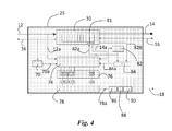
- the embodiment appearing in Figure 3 can be modified, as illustrated in Figure 4 .
- the look-ahead logic mechanism functions in the domain of the clock referred to the write operations, there is the need to synchronize the inputs of the decoder module 74 (i.e., the ones present on the right in Figure 4 ) with the output of the encoder module 78 (i.e., the look-ahead information present on the line 18).
- a local read pointer 82a in the first clock domain.
- the local pointer 82a is used for reading the FIFO queue at a local level and is compared in a comparison module 84 with the synchronised pointer present on the line 82b.
- the comparison serves to establish whether the FIFO queue has been read and whether the state variables are to be updated.
- an enable signal 84a that enables decrementing of the counter identified by the X bits present on the line 14a is generated by the comparison module 84.
- the output of the encoder 78 can be encoded according to a Gray code in a module 86, synchronised in a module 88, and decoded in a module 90.
- the approach for managing asynchronous FIFO queues can envisage the read pointer 82a being generated by the generator 82 in the read domain and being synchronised also with the write domain.
- the generator of the local pointer 82 can increment its output by one unit, and the decoder 74 can be authorised to decrement one of the counters 76 (the one selected via the value defined by the X bits coming from the output port of the local pointer 82a of the FIFO queue).
- the local read port of the FIFO queue works in the first clock domain and is managed by means of the local pointer 82a.
- the look-ahead information present on the line 18 can be synchronised via the typical brute-force approach, and, to avoid spurious values, also a Gray encoding can optionally be used.
- a separate FIFO queue 35 is created, which is addressed through a separate bus 92 and which contains the information on the state variables. Said approach is possible whenever there is no need to forward this information together with the inputs of the FIFO queue.
- the operation of writing in the separate FIFO queue is managed like that for the main FIFO queue (same write pointer WR and same control signals).
- the operation of reading of the separate FIFO queue in the synchronous case is managed like the one in the main FIFO queue, whereas in the asynchronous case it is managed by means of the local read pointer. However, in the asynchronous case there is no need to have a local read port in the main FIFO queue.
- the look-ahead solution described herein affords high performance (in terms of clocks) and a low cost (due to the area occupied). Furthermore, with said solution the look-ahead operation does not affect the performance of the queue. When working on an asynchronous queue, synchronisation is guaranteed to limit the risk of conditions of meta-stability.
- traffic management in such a way as to reorganize the accesses to the memory areas for optimizing system performance.
Landscapes
- Engineering & Computer Science (AREA)
- Theoretical Computer Science (AREA)
- Physics & Mathematics (AREA)
- General Engineering & Computer Science (AREA)
- General Physics & Mathematics (AREA)
- Communication Control (AREA)
- Multi Processors (AREA)
Abstract
Description
- The present disclosure relates to queue-management techniques and can be applied, for example, to managing first-in/first-out (FIFO) queues in the field of so-called systems-on-chip (SoCs).
- The disclosure has been developed with attention paid to its possible use in situations in which it is required to know in advance the contents of a queue, such as a FIFO queue ("look-ahead" function).
- System-on-chip technology today enables provision of even rather complex systems for communication between different modules of an integrated circuit (for example, a processing unit, memories, peripherals, and other dedicated units) so as to ensure observance of the specifications of performance of the system.
- Various applications envisage the use of first-in/first-out (FIFO) queues between devices with different clock frequencies. For example, a FIFO queue can be set between a first device, for example a microprocessor, which writes information in the FIFO queue and a second device, for example a peripheral or a second microprocessor, which reads the information from the FIFO queue. Each device reads and writes data in the FIFO queue with a rate equal to that of its own clock. However, FIFO queues can be used also in synchronous systems.
- In complex digital systems, the possibility of carrying out a sort of "anticipation" by investigating the subsequent contents of a queue, an operation that is also known by the term "look-ahead", can be particularly useful for anticipating execution of some processes or tasks and for implementing specific system functions.
- Currently, specific known solutions designed to solve this problem are not available.
- The inventors have noted that, in principle, the solution represented in
Figure 1 could be envisaged, in which, for search for a value, all the data stored in the FIFO queue are checked. In the communication between amaster node 10 and aslave node 20 control information is exchanged oncontrol lines 16. This occurs both in the case where the twonodes FIFO queue 30, getting them to travel on aninput line 12, whilst theslave node 20 is responsible for "reading" or extracting the data stored in thequeue 30 through anoutput line 14. Themaster node 10 thus works at a first end of theFIFO queue 30, whilst theslave node 20 works at the other end. The presence of theFIFO queue 30 serves to enable co-existence of the two domains with different clock frequency. TheFIFO queue 30 can be in particular a buffer used for regulating the flow of data in the communication between devices that work at different rates. - It will on the other hand be appreciated that, in on-chip communication systems, the use of buffers is not necessarily linked to the need to regulate the flow of data between devices that work at different speeds. Other examples of possible use of buffers are: protocol conversion, packeting as in the case of network-on-chip, or conversion of data size.
- The module designated in
Figure 1 by thereference number 25 represents the prediction, or look-ahead, unit. The solution here hypothesized envisages a parallel check of all the data stored in theFIFO queue 30. Each module contained in theunit 25, and designated by thereference number 40, is fundamentally a comparator module designed to compare the values present on itsinputs output 46 the desired value (which can be a value sought, the maximum value, or the minimum value). The value selected by thecomparator 40 is then made available at output and used as input for thenext comparator 40 in the cascade, which compares it with a next element in theFIFO queue 30. At the end of all the comparisons, the value sought is made available by theunit 25 at output on theline 18. - This solution would prove, however, very slow and costly: in fact, for a queue of size N, N-1 comparators are used and there is a long critical path constituted by the cascade of the comparators.
- Furthermore, this solution would prove far from flexible in so far as the length of the critical path and the production cost increase with the increase of the length of the queue.
- On the basis of the above premises, there emerges the need to have available an efficient, low-cost, and high-performance mechanism for executing the look-ahead operation in a queue, such as for example a FIFO queue. Such an approach is frequently required by components present in the system that are located downstream of the queue, for example for anticipating execution of a given task. The look-ahead technique substantially implies the fact of investigating the contents of a memory, for example to identify the maximum or minimum value of a subset of bits or for detecting the presence or otherwise of a given value within the queue, without carrying out an exhaustive check on said contents.
- The object of the invention is to provide a solution that is able to satisfy said requirements.
- According to the invention, said object is achieved thanks to a method having the characteristics referred to in the ensuing claims.
- The invention also refers to a corresponding device, as well as to a computer program product that can be loaded into the memory of at least one computer and comprises portions of software code that are able to implement the steps of the method when the product is run on at least one computer.
- As used herein, the reference to such a computer program product is understood as being equivalent to the reference to a computer-readable means containing instructions for control of the processing system for co-ordinating implementation of the method according to the invention. The reference to "at least one computer" is evidently meant to highlight the possibility of the present invention being implemented in a modular form and/or in a distributed form.
- The claims form an integral part of the technical teaching provided herein in relation to the invention.
- Various embodiments are suited to being applied to synchronous and asynchronous codes, likewise enabling at each cycle output of updated information from the queue.
- The invention will now be described, purely by way of non-limiting example, with reference to the annexed representations, in which:
-
Figure 1 has already been described previously; -
Figure 2 is a block diagram of the main steps of the solution described herein; -
Figure 3 shows a first embodiment in the case of a synchronous queue; -
Figure 4 shows a second embodiment in the case of an asynchronous queue; and -
Figure 5 shows an alternative embodiment. - Illustrated in the ensuing description are various specific details aimed at providing an in-depth understanding of the embodiments. The embodiments can be implemented without one or more of the specific details, or with other methods, components, materials, etc. In other cases, known structures, materials, or operations are not illustrated or described in detail so that various aspects of the embodiments will not be obscured.
- The reference to "an embodiment" or "one embodiment" in the framework of this description indicates that a particular configuration, structure or characteristic described in relation to the embodiment is comprised in at least one embodiment. Hence, phrases such as "in an embodiment" or "in one embodiment" that may be present in different points of this description do not necessarily refer to one and the same embodiment. Furthermore, particular conformations, structures, or characteristics can be combined adequately in one or more embodiments.
- The references are used herein only for convenience and hence do not define the sphere of protection or the scope of the embodiments.
- In particular, it will be appreciated that, whereas the present description draws attention, above all for simplicity of reference, to the application to queues of a FIFO type, various embodiments are suited to being used in relation to queues of any type.
- The general idea underlying various embodiments is that of managing a set of state variables, which, at each clock cycle, enable knowledge of the data stored in a queue, such as for example a FIFO queue. In this way, it is possible to avoid examination of all the data present in the FIFO queue by reading each item thereof, as in the case hypothesized with reference to
Figure 1 . - In various embodiments it is sufficient to examine the contents of some interfaces in which the state variables are updated only when a datum is written and/or read into/from the queue. These state variables are used for calculating the output value of the look-ahead mechanism.
- In various embodiments, the state variable associated to a value that is present n times in the FIFO queue has a value equal to n, whereas the state variable associated to a value that is not present in the FIFO queue has a nil value. If the aim of the look-ahead function is to examine the presence or otherwise of a given value, it is sufficient to have available just one state variable.
- The state variable could be in principle also a variable of a Boolean type, in which associated to each of the two states is the condition of value present or value absent. A variable of a Boolean type does not on the other hand enable management of situations in which various occurrences of the value sought are present in the queue.
- In general, the different state variables enable tracing of the presence of different values, whilst the possibility of the single variable assuming different values enables management of the situation in which there are several occurrences of that particular value in the queue.
- In the case where the aim is to find the maximum value or the minimum value among the data stored in a FIFO queue, the number of state variables can be equal to the number of values that the subset of data to be monitored can assume. Hence, there will be a state variable associated to each possible value that can be assumed by the elements in the queue. In this case, in various embodiments, it is possible to organize the state variables in a monotonically ordered sequence in which the position of each state variable corresponds to the data to which it is associated. The look-ahead function that entails identification of the datum in the queue having maximum or minimum value is performed by identifying said datum as the one corresponding to the state variable of non-nil value occupying one of the end positions in said ordered sequence.
- It will be appreciated that the solution can be extended also to look-ahead operations of a more complex nature, such as for example determination of the average (for example, weighted average) of the values of the data in the queue. Each state variable identifies in fact a corresponding data value, and the value assumed by the variable indicates how many times (never, once or else a number of times, and how many times) said value is present. In fact, with the solution described herein, the set of the state variables, and the values assumed thereby, constitute in practice a "histogram" of the contents of the queue designed to be updated whenever a value is written (entered) in and/or read (extracted) from the FIFO queue.
- In various embodiments, during each clock cycle, only the value of a state variable is incremented or decremented by one unit.
- As has been seen, the state variables can be obtained, for example, by means of counters, and each counter must be able to count up to a value equal to the length of the FIFO queue (in the case where stored in the FIFO queue are values that are all equal, the state variable associated to said value will assume a value equal to the length of the queue).
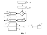
- The steps of the example of embodiment considered herein are illustrated with reference to the flowchart of
Figure 2 and are executed at each clock cycle to obtain at output the result of the look-ahead scanning. - Detected in a step 50 is a write/read event that concerns the
FIFO queue 30. In thestep 52 the datum is decoded and control passes to thenext selection step 54. In the case of a read operation, in astep 56 the state variable addressed by the index Wi and regarding write operations is decremented. Instead, in the case of a read operation, in a step 58 a state variable addressed by the index Ri and regarding read operations is incremented. Finally, in the case of a combined read and write operation, in astep 60 the state variable addressed by the index Ri is incremented, and in astep 62 the state variable addressed by the index Wi is decremented. - In any case, at the end of these operations of updating of the state variables it is possible to continue with the
step 64 in which the index of the box of the FIFO queue that contains the maximum value or the minimum value is identified. In particular, in a step 64a the maximum index from among the non-nil variables is sought, and this index identifies the position in which the maximum value is located. In like manner, in a step 64b the minimum index from among the non-nil variables is sought, and this index identifies the position in which the minimum value is located. At output fromstep 64 there is the index that identifies the position of the value sought. Finally, in astep 66 the index is encoded and at thenext step 68 the maximum value/minimum value sought is made available. - In practice, synchronous queues and asynchronous queues are used, and in what follows the different architectures of the units for execution of the look-ahead operations will be described in detail.
- With reference to
Figures 3 and4 , two possible embodiments are illustrated in the synchronous case and in the asynchronous case, respectively. As compared to the solution illustrated inFigure 1 , the cascade of comparator modules is replaced by a series of modules, the functions of which will be described hereinafter. - In the more general case, the FIFO queue is able to manage the control flow both at the input interfaces and at the output interfaces (usually this function is based upon a validation and acknowledgement protocol).
- The
modules modules - The modules C1, C2,... CK contained in the
module 76 are counter modules. The number of counters K is equal to the number of the possible values that the X bits present on thelines module 76 has a dimension equal to the value of the length of the FIFO queue. The output logic has the function of detecting when the output of the counter is other than zero. - The
decoder module 74 enables: - incrementing by one unit of the value contained in the counter identified via the X bits present on the
line 12a if a write operation is identified, i.e., if an enable signal arrives at input on theline 70a; - decrementing by one unit of the value contained in the counter identified via the X bits present on the
line 14a if a read operation is identified, i.e., if an enable signal arrives at input on theline 72a. - The function of the
encoder module 78 depends instead upon the particular type of look-ahead operation to be executed. - As mentioned previously, in various embodiments the number K of the counters C1, C2,... CK is equal to the number of values that the elements of the FIFO queue can assume. The counter C1 is associated to the lowest value that can be present within the FIFO queue, whilst the counter CK is associated to the highest value that can be present within the FIFO queue. If a counter CJ is zero it means that the value associated thereto is not present in the FIFO queue. In fact, not necessarily all the possible values are present simultaneously in the queue. A single value can be repeated a number of times and others may not be present within the FIFO queue.
- There are hence present K counters, and each counter other than zero indicates the presence in the FIFO queue of the value associated to the counter. Furthermore, if the contents of the counter is greater than 1 it means that the value is present a number of times in the FIFO queue (and this means that there will be at least one nil counter).
- In the case where the maximum value is sought, the output of the
encoder 78 corresponds to the input value other than zero that is in the position on the extreme right; i.e., the counter other than zero with the highest index is sought (starting from K down to 1). - Instead, in the case where the minimum value is sought, the output of the
encoder 78 corresponds to the input value other than zero that is in the position on the extreme left; i.e., the counter other than zero with the lowest index is sought (starting from 1 up to K). - Alternatively, to verify whether a given value is present or otherwise in the FIFO queue, it is sufficient to verify whether the output of the corresponding counter is other than zero.
- In general, in one and the same look-
ahead unit 25, multiple decoding techniques can be implemented in order to obtain different look-ahead information at the same time. - The register module 80 (which is an optional module) has the purpose of re-timing the output, in order to break the combinational path and have a sufficient margin in terms of time.
- Tests conducted in 65-nm technology have shown that the
encoder 78 can function properly at frequencies in the region of 700 MHz. - In the asynchronous case, the FIFO queues are generally written and read using different clocks that are not synchronised with one another. In this case, the embodiment appearing in
Figure 3 can be modified, as illustrated inFigure 4 . - Since, according to the approach proposed, the look-ahead logic mechanism functions in the domain of the clock referred to the write operations, there is the need to synchronize the inputs of the decoder module 74 (i.e., the ones present on the right in
Figure 4 ) with the output of the encoder module 78 (i.e., the look-ahead information present on the line 18). - For this purpose, it is possible to envisage the use of a synchronisation chain, implemented according to the typical "brute force" approach, to be used at output from the encoder. The same approach in the case of the inputs of the encoder could cause the loss of data, and in turn the loss of data would alter the value of the state variables, thus damaging execution of the method.
- In this regard, it is possible to generate, in a
generator module 82, alocal read pointer 82a in the first clock domain. Thelocal pointer 82a is used for reading the FIFO queue at a local level and is compared in acomparison module 84 with the synchronised pointer present on theline 82b. The comparison serves to establish whether the FIFO queue has been read and whether the state variables are to be updated. Whenever the local pointer is different from the synchronised pointer, an enablesignal 84a that enables decrementing of the counter identified by the X bits present on theline 14a is generated by thecomparison module 84. - Finally, the output of the
encoder 78 can be encoded according to a Gray code in amodule 86, synchronised in amodule 88, and decoded in amodule 90. - Finally, presented hereinafter are some observations useful for understanding operation of various embodiments of the architecture of
Figure 4 . - The approach for managing asynchronous FIFO queues can envisage the
read pointer 82a being generated by thegenerator 82 in the read domain and being synchronised also with the write domain. - When the
local pointer 82a differs from the synchronized one, the generator of thelocal pointer 82 can increment its output by one unit, and thedecoder 74 can be authorised to decrement one of the counters 76 (the one selected via the value defined by the X bits coming from the output port of thelocal pointer 82a of the FIFO queue). - The local read port of the FIFO queue works in the first clock domain and is managed by means of the
local pointer 82a. - The look-ahead information present on the
line 18 can be synchronised via the typical brute-force approach, and, to avoid spurious values, also a Gray encoding can optionally be used. - According to the particular application, a different approach can be used, consisting in the storage of the necessary information in a separate FIFO queue, as illustrated in
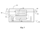
Figure 5 . - In particular, a
separate FIFO queue 35 is created, which is addressed through aseparate bus 92 and which contains the information on the state variables. Said approach is possible whenever there is no need to forward this information together with the inputs of the FIFO queue. The operation of writing in the separate FIFO queue is managed like that for the main FIFO queue (same write pointer WR and same control signals). The operation of reading of the separate FIFO queue in the synchronous case is managed like the one in the main FIFO queue, whereas in the asynchronous case it is managed by means of the local read pointer. However, in the asynchronous case there is no need to have a local read port in the main FIFO queue. - In general, the solution proposed is used when there is the need to analyse a particular subset of bits.
- Other typical applications are:
- management of the quality of service (QoS) in on-chip communications systems (for example, networks-on-chip);
- memory controllers for reorganizing and optimizing accesses to the memory; and
- central processing units (CPUs) of a general-purpose or specialized type for optimizing execution of a pipeline type.
- The look-ahead solution described herein affords high performance (in terms of clocks) and a low cost (due to the area occupied). Furthermore, with said solution the look-ahead operation does not affect the performance of the queue. When working on an asynchronous queue, synchronisation is guaranteed to limit the risk of conditions of meta-stability.
- Other possible applications are represented by traffic management in such a way as to reorganize the accesses to the memory areas for optimizing system performance.
- Of course, without prejudice to the principle of the invention, the details and the embodiments may vary, even significantly, with respect to what has been described herein purely by way of example, without thereby departing from the scope of the invention, as defined by the annexed claims. In particular, it should be emphasized that, whilst the present description has concentrated attention on its application to queues of a FIFO type, various embodiments are suited to being used in relation to queues of any type.
Claims (8)
- A method of managing a queue (30) and performing a look-ahead function of the data in the queue (30), including:- associating to the data in the queue respective state variables (C1, C2, ..., CK) having values representative of the number of times a given datum is present in the queue (30), and- performing said look-ahead function on said respective state variables.
- The method of claim 1, including using state variables (C1, C2, ..., CK) in a number equal to the number of different values which may be assumed by said data in the queue (30).
- The method of one of claims 1 or 2, wherein said look-ahead function involves detecting the presence of a given datum in said queue (30) and is performed by checking whether among said state variables (C1, C2, ..., CK) there exists a corresponding state variable having a non-nil value.
- The method of any claims 1 to 3, including arranging said state variables (C1, C2, ..., CK) in a monotonically ordered sequence wherein said state variables (C1, C2, ..., CK) are ordered according to the values of the data to which they are associated, and wherein said look-ahead function involves identifying a datum in the queue having either a maximum or minimum value and is performed by identifying said datum as the one corresponding to the state variable having a non-nil value occupying one of the end positions in said ordered sequence.
- The method of any of the previous claims, including:- detecting the writing or the reading of a datum in said queue (30),- incrementing by one unit the value of the respective associated state variable when the datum is written in the queue (30), and- decreasing by one unit the value of the respective associated state variable when the datum is read from the queue (30).
- The method of the previous claims, wherein said queue (30) is a FIFO queue.
- Device for performing a look-ahead operation in a queue (30), the device adapted for performing the method of any of claims 1 to 6.
- A computer program product including software code portions for performing the method of any of claims 1 to 6, when the product is run on a computer.
Applications Claiming Priority (1)
| Application Number | Priority Date | Filing Date | Title |
|---|---|---|---|
| ITTO20090927 | 2009-11-27 |
Publications (1)
| Publication Number | Publication Date |
|---|---|
| EP2328074A1 true EP2328074A1 (en) | 2011-06-01 |
Family
ID=42103061
Family Applications (1)
| Application Number | Title | Priority Date | Filing Date |
|---|---|---|---|
| EP10191212A Withdrawn EP2328074A1 (en) | 2009-11-27 | 2010-11-15 | Queue management |
Country Status (2)
| Country | Link |
|---|---|
| US (1) | US8688872B2 (en) |
| EP (1) | EP2328074A1 (en) |
Families Citing this family (5)
| Publication number | Priority date | Publication date | Assignee | Title |
|---|---|---|---|---|
| WO2016205732A2 (en) | 2015-06-19 | 2016-12-22 | Apple Inc. | Measurement denoising |
| CN109802896B (en) * | 2017-11-16 | 2022-04-22 | 华为技术有限公司 | Method for scheduling data and switching equipment |
| US11709835B2 (en) | 2018-10-15 | 2023-07-25 | Ocient Holdings LLC | Re-ordered processing of read requests |
| US11249916B2 (en) | 2018-10-15 | 2022-02-15 | Ocient Holdings LLC | Single producer single consumer buffering in database systems |
| US11256696B2 (en) * | 2018-10-15 | 2022-02-22 | Ocient Holdings LLC | Data set compression within a database system |
Citations (4)
| Publication number | Priority date | Publication date | Assignee | Title |
|---|---|---|---|---|
| US5237683A (en) * | 1989-11-06 | 1993-08-17 | Masaru Kitsuregawa | Method and apparatus for data distribution |
| US5319583A (en) * | 1992-06-22 | 1994-06-07 | General Electric Company | Digital computer sliding-window minimum filter |
| EP1315100A1 (en) * | 2000-07-31 | 2003-05-28 | Turbo Data Laboratories, Inc. | Data compiling method |
| US20060155924A1 (en) * | 2004-12-15 | 2006-07-13 | Dwyer Michael K | Hardware stack having entries with a data portion and associated counter |
Family Cites Families (27)
| Publication number | Priority date | Publication date | Assignee | Title |
|---|---|---|---|---|
| JPS633356A (en) * | 1986-06-23 | 1988-01-08 | Hitachi Ltd | Information processor |
| JPS63232626A (en) * | 1987-03-20 | 1988-09-28 | Fujitsu Ltd | Data compression restoration system |
| US5214607A (en) * | 1990-11-26 | 1993-05-25 | Ncr Corporation | Look-ahead FIFO byte count apparatus |
| JPH05108297A (en) * | 1991-10-21 | 1993-04-30 | Canon Inc | Character processing method |
| US5396595A (en) * | 1992-04-24 | 1995-03-07 | Spacelabs Medical, Inc. | Method and system for compression and decompression of data |
| US6219773B1 (en) * | 1993-10-18 | 2001-04-17 | Via-Cyrix, Inc. | System and method of retiring misaligned write operands from a write buffer |
| JPH0851621A (en) * | 1994-08-08 | 1996-02-20 | Canon Inc | Encoding method and device |
| US5893924A (en) * | 1995-07-28 | 1999-04-13 | International Business Machines Corporation | System and method for overflow queue processing |
| US6233256B1 (en) * | 1996-03-13 | 2001-05-15 | Sarnoff Corporation | Method and apparatus for analyzing and monitoring packet streams |
| GB9606084D0 (en) * | 1996-03-22 | 1996-05-22 | D2B Systems Co Ltd | Data frame buffering |
| US6487212B1 (en) * | 1997-02-14 | 2002-11-26 | Advanced Micro Devices, Inc. | Queuing structure and method for prioritization of frames in a network switch |
| US6920112B1 (en) * | 1998-06-29 | 2005-07-19 | Cisco Technology, Inc. | Sampling packets for network monitoring |
| US6233231B1 (en) * | 1998-12-03 | 2001-05-15 | Motorola, Inc. | Data transmission within a spread-spectrum communication system |
| US6614798B1 (en) * | 1999-03-30 | 2003-09-02 | Integrated Device Technology, Inc. | Asynchronous FIFO increment and decrement control for interfaces that operate at differing clock frequencies |
| US7027547B1 (en) * | 2001-10-05 | 2006-04-11 | Crest Microsystems | Method and apparatus for matching transmission rates across a single channel |
| US7187689B1 (en) * | 2001-10-29 | 2007-03-06 | Juniper Networks, Inc. | Self-cleaning mechanism for error recovery |
| JP2006185162A (en) * | 2004-12-27 | 2006-07-13 | Hitachi Global Storage Technologies Netherlands Bv | Data storage device and control method for the same |
| US7275124B2 (en) * | 2005-02-24 | 2007-09-25 | International Business Machines Corporation | Method and system for controlling forwarding or terminating of a request at a bus interface based on buffer availability |
| US20070005742A1 (en) * | 2005-06-30 | 2007-01-04 | Avigdor Eldar | Efficient network communications via directed processor interrupts |
| US7818744B2 (en) * | 2005-12-30 | 2010-10-19 | Intel Corporation | Apparatus and method for redundant software thread computation |
| US8867683B2 (en) * | 2006-01-27 | 2014-10-21 | Ati Technologies Ulc | Receiver and method for synchronizing and aligning serial streams |
| US7860335B2 (en) * | 2006-12-04 | 2010-12-28 | The Boeing Company | Method and apparatus for smart signal averaging |
| US8149240B2 (en) * | 2007-02-07 | 2012-04-03 | Microsoft Corporation | Efficient symbolic differentiation using derivative graph factorization |
| US7716396B1 (en) * | 2007-02-09 | 2010-05-11 | Juniper Networks, Inc. | Multi-reader multi-writer circular buffer memory |
| EP2094039B1 (en) * | 2008-02-20 | 2016-11-09 | Amazon Technologies, Inc. | Method and apparatus for processing padding buffer status reports |
| US20090276673A1 (en) * | 2008-05-05 | 2009-11-05 | Industrial Technology Research Institute | Methods and systems for optimizing harq communication |
| US8213360B2 (en) * | 2009-04-29 | 2012-07-03 | Nokia Corporation | Apparatus and method for flexible switching between device-to-device communication mode and cellular communication mode |
-
2010
- 2010-11-15 EP EP10191212A patent/EP2328074A1/en not_active Withdrawn
- 2010-11-22 US US12/951,268 patent/US8688872B2/en active Active
Patent Citations (4)
| Publication number | Priority date | Publication date | Assignee | Title |
|---|---|---|---|---|
| US5237683A (en) * | 1989-11-06 | 1993-08-17 | Masaru Kitsuregawa | Method and apparatus for data distribution |
| US5319583A (en) * | 1992-06-22 | 1994-06-07 | General Electric Company | Digital computer sliding-window minimum filter |
| EP1315100A1 (en) * | 2000-07-31 | 2003-05-28 | Turbo Data Laboratories, Inc. | Data compiling method |
| US20060155924A1 (en) * | 2004-12-15 | 2006-07-13 | Dwyer Michael K | Hardware stack having entries with a data portion and associated counter |
Also Published As
| Publication number | Publication date |
|---|---|
| US20110131189A1 (en) | 2011-06-02 |
| US8688872B2 (en) | 2014-04-01 |
Similar Documents
| Publication | Publication Date | Title |
|---|---|---|
| US10318468B2 (en) | FPGA-based interface signal remapping method | |
| CN107608750B (en) | Device for pattern recognition | |
| US6389489B1 (en) | Data processing system having a fifo buffer with variable threshold value based on input and output data rates and data block size | |
| US8677045B2 (en) | Transaction reordering system and method with protocol indifference | |
| US8688872B2 (en) | Method and device for managing queues, and corresponding computer program product | |
| EP2579164B1 (en) | Multiprocessor system, execution control method, execution control program | |
| CN105320490A (en) | Method and apparatus for asynchronous FIFO circuit | |
| CN105701266B (en) | Method and system for the static timing analysis in circuit design | |
| US20120079148A1 (en) | Reordering arrangement | |
| US9141569B2 (en) | Tracking a relative arrival order of events being stored in multiple queues using a counter | |
| CN101727423B (en) | System capable of preempting multiple hardware tasks on reconfigurable FPGA and implementing method thereof | |
| CN104050028A (en) | Method and apparatus to trigger and trace on-chip system fabric transactions within the primary scalable fabric | |
| CN114490251A (en) | Log processing system, log processing method and terminal equipment | |
| CN113010116A (en) | Data processing method and device, terminal equipment and readable storage medium | |
| CN100349442C (en) | Ping pong buffer device | |
| US20040006724A1 (en) | Network processor performance monitoring system and method | |
| CN112749106A (en) | FPGA-based interrupt management method | |
| JP2014211813A (en) | Trace collection circuit and trace collection method | |
| US8468394B2 (en) | Method of tracing selected activities within a data processing system by tagging selected items and tracing the tagged items | |
| US9582438B2 (en) | Method and apparatus for identifying cause of interrupt | |
| US8959398B2 (en) | Multiple clock domain debug capability | |
| US7000148B2 (en) | Program-controlled unit | |
| CN114830103A (en) | Tracking handler module system and method of using the same | |
| US11704218B2 (en) | Information processing apparatus and information processing method to analyze a state of dynamic random access memory (DRAM) | |
| CN115048220A (en) | Dynamic data competition detection method, device, terminal and storage medium |
Legal Events
| Date | Code | Title | Description |
|---|---|---|---|
| PUAI | Public reference made under article 153(3) epc to a published international application that has entered the european phase |
Free format text: ORIGINAL CODE: 0009012 |
|
| AK | Designated contracting states |
Kind code of ref document: A1 Designated state(s): AL AT BE BG CH CY CZ DE DK EE ES FI FR GB GR HR HU IE IS IT LI LT LU LV MC MK MT NL NO PL PT RO RS SE SI SK SM TR |
|
| AX | Request for extension of the european patent |
Extension state: BA ME |
|
| 17P | Request for examination filed |
Effective date: 20111128 |
|
| RAP1 | Party data changed (applicant data changed or rights of an application transferred) |
Owner name: STMICROELECTRONICS SRL |
|
| 17Q | First examination report despatched |
Effective date: 20140612 |
|
| STAA | Information on the status of an ep patent application or granted ep patent |
Free format text: STATUS: THE APPLICATION HAS BEEN WITHDRAWN |
|
| 18W | Application withdrawn |
Effective date: 20140903 |