JP4545109B2 - Communication path control device - Google Patents
Communication path control device Download PDFInfo
- Publication number
- JP4545109B2 JP4545109B2 JP2006089134A JP2006089134A JP4545109B2 JP 4545109 B2 JP4545109 B2 JP 4545109B2 JP 2006089134 A JP2006089134 A JP 2006089134A JP 2006089134 A JP2006089134 A JP 2006089134A JP 4545109 B2 JP4545109 B2 JP 4545109B2
- Authority
- JP
- Japan
- Prior art keywords
- wireless
- communication path
- packet
- communication
- network
- Prior art date
- Legal status (The legal status is an assumption and is not a legal conclusion. Google has not performed a legal analysis and makes no representation as to the accuracy of the status listed.)
- Expired - Fee Related
Links
Images


Classifications
-
- H—ELECTRICITY
- H04—ELECTRIC COMMUNICATION TECHNIQUE
- H04M—TELEPHONIC COMMUNICATION
- H04M7/00—Arrangements for interconnection between switching centres
- H04M7/006—Networks other than PSTN/ISDN providing telephone service, e.g. Voice over Internet Protocol (VoIP), including next generation networks with a packet-switched transport layer
-
- H—ELECTRICITY
- H04—ELECTRIC COMMUNICATION TECHNIQUE
- H04L—TRANSMISSION OF DIGITAL INFORMATION, e.g. TELEGRAPHIC COMMUNICATION
- H04L45/00—Routing or path finding of packets in data switching networks
-
- H—ELECTRICITY
- H04—ELECTRIC COMMUNICATION TECHNIQUE
- H04W—WIRELESS COMMUNICATION NETWORKS
- H04W40/00—Communication routing or communication path finding
- H04W40/34—Modification of an existing route
Description
本発明は、複数の無線IPネットワークに接続可能な無線通信装置との通信経路を制御する通信経路制御装置及び通信経路制御方法、複数の無線IPネットワークに接続可能な無線通信装置及び無線通信装置の通信方法に関する。 The present invention relates to a communication path control apparatus and a communication path control method for controlling a communication path with a wireless communication apparatus connectable to a plurality of wireless IP networks, a wireless communication apparatus connectable to a plurality of wireless IP networks, and a wireless communication apparatus. It relates to a communication method.
近年、インターネットプロトコル(IP)に対応したIPネットワークの普及が著しい。IPネットワークの普及に伴い、いわゆるVoIP技術を用いて音声信号をIPパケット(以下、音声IPパケット)に変換し、IPネットワークを介して音声IPパケットを伝送することが一般的になりつつある。 In recent years, the spread of IP networks corresponding to the Internet Protocol (IP) has been remarkable. With the spread of IP networks, it is becoming common to convert voice signals into IP packets (hereinafter referred to as voice IP packets) using so-called VoIP technology and transmit voice IP packets via the IP network.
このように、IPネットワークを介して音声IPパケットを伝送する場合において、IPネットワークの通信品質(例えば、IPパケットの伝送遅延時間)に基づいて、電話端末間の通信経路を切り替える方法が開示されている(例えば、特許文献1)。 Thus, a method for switching a communication path between telephone terminals based on communication quality of an IP network (for example, a transmission delay time of an IP packet) when a voice IP packet is transmitted through an IP network is disclosed. (For example, Patent Document 1).
当該方法では、RTP(real-time transport protocol)を用いて音声IPパケットが伝送される。また、音声IPパケットのセッションを制御するため、RTCP(RTP control protocol)が用いられる。音声IPパケットの受信側では、受信したRTCPパケットに含まれる情報からIPネットワークの通信品質が判定され、判定結果に応じて電話端末間の通信経路が切り替えられる。
しかしながら、上述した通信経路を切り替える方法には、次のような問題があった。すなわち、RTCPパケットの平均的な送信間隔が長い(2秒程度)ため、無線基地局などによって構成される無線IPネットワークでは、フェージングなど、急激な通信品質の劣化に対応することができない場合が発生する。 However, the above-described method for switching communication paths has the following problems. In other words, since the average transmission interval of RTCP packets is long (about 2 seconds), there may be cases where wireless IP networks configured with wireless base stations cannot cope with rapid communication quality degradation such as fading. To do.
また、複数の無線IPネットワーク(例えば、携帯電話ネットワークと無線LANネットワーク)間において通信経路を切り替える場合、無線IPネットワークの下り方向における通信品質の劣化に対しては、無線通信装置が切り替えを主導することができる。一方、無線IPネットワークの上り方向における通信品質の劣化に対しては、受信側の通信制御装置において、無線IPネットワークの無線状態や通信品質の劣化を把握することが困難なため、他の無線IPネットワークを経由した通信経路への切り替えを行うべきか否かを判定することができないといった問題があった。また、送信後の無線通信装置においても、受信側における通信品質の劣化を把握することが困難なため、同様の問題があった。 Further, when switching communication paths between a plurality of wireless IP networks (for example, a mobile phone network and a wireless LAN network), the wireless communication device takes the lead in switching the communication quality in the downlink direction of the wireless IP network. be able to. On the other hand, for the deterioration of communication quality in the uplink direction of the wireless IP network, it is difficult for the communication control device on the receiving side to grasp the wireless state of the wireless IP network and the deterioration of communication quality. There has been a problem that it is impossible to determine whether or not to switch to a communication path via a network. Further, the wireless communication apparatus after transmission has the same problem because it is difficult to grasp the deterioration of communication quality on the receiving side.
そこで、本発明は、このような状況に鑑みてなされたものであり、無線IPネットワークを経由して音声IPパケットを伝送する場合において、急激な通信品質の劣化にも対応しつつ、異なる無線IPネットワークを経由する通信経路への適切な切り替えを行うことができる通信経路制御装置、無線通信装置、通信経路制御方法及び無線通信装置の通信方法を提供することを目的とする。 Therefore, the present invention has been made in view of such a situation, and in the case of transmitting a voice IP packet via a wireless IP network, different wireless IPs can be used while dealing with a sudden deterioration in communication quality. It is an object of the present invention to provide a communication path control device, a wireless communication device, a communication path control method, and a communication method for a wireless communication device that can perform appropriate switching to a communication path via a network.
上述した問題を解決するため、本発明は、次のような特徴を有している。まず、本発明の第1の特徴は、音声信号がIPパケットに変換された音声IPパケット(例えば、VoIPパケットP11)を伝送する第1の無線IPネットワーク(無線IPネットワーク10A)、及び前記第1の無線IPネットワークと異なる第2の無線IPネットワーク(無線IPネットワーク10B)に接続可能な無線通信装置(例えば、携帯電話端末300A)との通信経路(通信経路R1,R2)を制御する通信経路制御装置(スイッチングサーバ100)であって、前記無線通信装置から通信先(IP電話端末42)に向けて送信された前記音声IPパケットを中継する中継部(MN側受信制御部113及びCN側通信経路制御部119)と、前記中継部が受信した受信音声IPパケットの受信時刻を順次取得する受信時刻取得部(MN側受信制御部113)と、前記受信時刻取得部が取得した複数の前記受信時刻に基づいて、前記通信経路を前記第1の無線IPネットワーク経由から、前記第2の無線IPネットワーク経由に切り替える通信経路制御部(送信パケット振り分け部109及び通信経路制御部111)と
を備えることを要旨とする。
In order to solve the problems described above, the present invention has the following features. First, a first feature of the present invention is that a first wireless IP network (
このような通信経路制御装置によれば、無線通信装置から通信先に向けて送信された複数の音声IPパケットの受信時刻に基づいて、通信経路が、第1の無線IPネットワーク経由から第2の無線IPネットワーク経由に切り替えられる。このため、無線IPネットワークの上り方向における通信品質の劣化した場合でも、通信経路を第1の無線IPネットワークから第2の無線IPネットワーク経由に切り替えることができる。 According to such a communication path control device, the communication path is routed from the first wireless IP network to the second based on the reception times of the plurality of voice IP packets transmitted from the wireless communication device to the communication destination. It can be switched via the wireless IP network. For this reason, even when the communication quality in the upstream direction of the wireless IP network deteriorates, the communication path can be switched from the first wireless IP network to the second wireless IP network.
また、このような通信経路制御装置によれば、音声信号がIPパケットに変換された音声IPパケットの受信時刻に基づいて通信経路を切り替えるか否かが即座に判定されるため、平均的な送信間隔が長いRTCPパケットなどを用いる場合と比較して、通信品質の劣化に迅速に対応することができる。すなわち、このような通信経路制御装置によれば、フェージングなど、急激な通信品質の劣化が生じ得る無線IPネットワークにも対応することができる。 Further, according to such a communication path control device, it is immediately determined whether or not to switch the communication path based on the reception time of the voice IP packet in which the voice signal is converted into the IP packet. Compared with the case of using RTCP packets having a long interval, it is possible to quickly cope with deterioration of communication quality. That is, according to such a communication path control device, it is possible to cope with a wireless IP network in which rapid communication quality degradation such as fading may occur.
本発明の第2の特徴は、本発明の第1の特徴に係り、前記通信経路制御部は、前記受信音声IPパケットの受信時刻に基づいて所定の基準時刻(時刻t0)からの経過時間を演算し、前記受信音声IPパケットのシーケンス番号(seq)及び前記受信音声IPパケットの時間長(例えば、20ms)を用いて求められる標準伝送時間と、前記経過時間との差に基づいて、前記通信経路を前記第1の無線IPネットワーク経由から、前記第2の無線IPネットワーク経由に切り替えることを要旨とする。 A second feature of the present invention relates to the first feature of the present invention, wherein the communication path control unit calculates an elapsed time from a predetermined reference time (time t0) based on a reception time of the received voice IP packet. Based on the difference between the elapsed time and the standard transmission time calculated using the sequence number (seq) of the received voice IP packet and the time length (for example, 20 ms) of the received voice IP packet. The gist is to switch the route from the first wireless IP network to the second wireless IP network.
本発明の第3の特徴は、本発明の第1の特徴に係り、前記音声信号の符号化に用いられる音声符号化則は、前記第1の無線IPネットワークと、前記第2の無線IPネットワークとにおいて異なることを要旨とする。 A third feature of the present invention relates to the first feature of the present invention, and the speech coding rules used for coding the speech signal are the first wireless IP network and the second wireless IP network. The difference is that.
本発明の第4の特徴は、本発明の第1の特徴に係り、前記音声IPパケットは、所定の無線フレームに割り当てられ、前記無線フレームの構成は、前記第1の無線IPネットワークと、前記第2の無線IPネットワークとにおいて異なることを要旨とする。 A fourth feature of the present invention relates to the first feature of the present invention, wherein the voice IP packet is assigned to a predetermined radio frame, and the configuration of the radio frame includes the first radio IP network, The gist is that it differs from the second wireless IP network.
本発明の第5の特徴は、本発明の第1の特徴に係り、前記第1の無線IPネットワークは、前記無線通信装置との無線通信を実行する複数の無線基地局(無線基地局11,12)を備え、前記通信経路制御部は、同一の無線基地局との無線通信を実行する複数の無線通信装置(携帯電話端末300A,300B及び300N)との前記通信経路を切り替える場合、前記複数の無線通信装置のうち、一部の無線通信装置(例えば、携帯電話端末300A)との前記通信経路を切り替え、前記一部の無線通信装置との前記通信経路の切り替えが完了した後、前記受信時刻取得部が取得した複数の前記受信時刻に基づいて、前記一部の無線通信装置を除く残りの無線通信装置(携帯電話端末300B,300N)との前記通信経路を切り替えるか否かを判定することを要旨とする。
A fifth feature of the present invention relates to the first feature of the present invention, wherein the first wireless IP network includes a plurality of wireless base stations (
また、前記通信経路制御装置は、既に受信した受信音声IPパケットの平均受信間隔と、最新の受信音声IPパケットの受信間隔とに基づいて、音声IPパケットの送信が停止されているか否かを判定する制御装置側無音検出部(無音検出部107)をさらに備え、前記制御装置側無音検出部によって前記音声IPパケットの送信が停止されていると判定されている間、前記通信経路制御部が前記通信経路の切り替えを中止するようにしてもよい。 Further, the communication path control device determines whether or not the transmission of the voice IP packet is stopped based on the average reception interval of the received voice IP packet that has already been received and the reception interval of the latest received voice IP packet. A control device side silence detection unit (silence detection unit 107), and while the control device side silence detection unit determines that transmission of the voice IP packet is stopped, the communication path control unit You may make it cancel switching of a communication path.
本発明の第6の特徴は、音声信号がIPパケットに変換された音声IPパケット(例えば、VoIPパケットP11)を伝送する第1の無線IPネットワーク(無線IPネットワーク10A)、及び前記第1の無線IPネットワークと異なる第2の無線IPネットワーク(無線IPネットワーク10B)に接続可能な無線通信装置(例えば、携帯電話端末300A)であって、前記音声IPパケットを前記第1の無線IPネットワークまたは前記第2の無線IPネットワークを経由して送受信する送受信部(受信制御部307及び送信パケット振り分け部309)と、前記音声IPパケットが所定の間隔で送信されているか否かを検出する無音検出部(無音検出部315)と、前記無音検出部によって前記音声IPパケットの送信が停止されていると判定されている間、前記停止まで前記送受信部が前記音声IPパケットを送信していた前記第1の無線IPネットワークを経由して、前記音声IPパケットの擬似パケットを所定の間隔で送信する擬似パケット送信部(送信パケット振り分け部309及び擬似パケット生成部311)とを備えることを要旨とする。
A sixth feature of the present invention is that a first wireless IP network (
本発明の第7の特徴は、音声信号がIPパケットに変換された音声IPパケットを伝送する第1の無線IPネットワーク、及び前記第1の無線IPネットワークと異なる第2の無線IPネットワークに接続可能な無線通信装置との通信経路を制御する通信経路制御方法が、前記無線通信装置から通信先に向けて送信された前記音声IPパケットを受信するステップと、前記受信した受信音声IPパケットの受信時刻を順次取得するステップと、前記取得した複数の前記受信時刻に基づいて、前記通信経路を前記第1の無線IPネットワーク経由から、前記第2の無線IPネットワーク経由に切り替えるステップとを含むことを要旨とする。 The seventh feature of the present invention is that it is connectable to a first wireless IP network that transmits a voice IP packet in which a voice signal is converted into an IP packet, and a second wireless IP network that is different from the first wireless IP network. A communication path control method for controlling a communication path with a wireless communication device receiving the voice IP packet transmitted from the wireless communication device to a communication destination; and a reception time of the received received voice IP packet And sequentially switching the communication path from the first wireless IP network to the second wireless IP network based on the acquired plurality of the reception times. And
本発明の第8の特徴は、音声信号がIPパケットに変換された音声IPパケットを伝送する第1の無線IPネットワーク、及び前記第1の無線IPネットワークと異なる第2の無線IPネットワークに接続可能な無線通信装置の通信方法が、前記音声IPパケットを前記第1の無線IPネットワークまたは前記第2の無線IPネットワークを経由して送受信するステップと、前記音声IPパケットを所定の間隔で送信しているか否かを検出するステップと、前記音声IPパケットの送信が停止されていると判定されている間、前記停止まで前記音声IPパケットを送信していた前記第1の無線IPネットワークを経由して、前記音声IPパケットの擬似パケットを所定の間隔で送信するステップとを含むことを要旨とする。 The eighth feature of the present invention is that it is connectable to a first wireless IP network that transmits a voice IP packet in which a voice signal is converted into an IP packet, and a second wireless IP network that is different from the first wireless IP network. A communication method of a wireless communication device comprising: transmitting and receiving the voice IP packet via the first wireless IP network or the second wireless IP network; and transmitting the voice IP packet at a predetermined interval. A step of detecting whether or not transmission of the voice IP packet is stopped while the first wireless IP network that has been transmitting the voice IP packet until the stop is determined. And a step of transmitting the pseudo packet of the voice IP packet at a predetermined interval.
本発明の特徴によれば、無線IPネットワークを経由して音声IPパケットを伝送する場合において、急激な通信品質の劣化にも対応しつつ、異なる無線IPネットワークを経由する通信経路への適切な切り替えを行うことができる通信経路制御装置、無線通信装置、通信経路制御方法及び無線通信装置の通信方法を提供することができる。 According to the features of the present invention, when voice IP packets are transmitted via a wireless IP network, appropriate switching to a communication path via a different wireless IP network while accommodating a sudden deterioration in communication quality. It is possible to provide a communication path control apparatus, a radio communication apparatus, a communication path control method, and a communication method for the radio communication apparatus that can perform the above.
次に、本発明の実施形態について説明する。なお、以下の図面の記載において、同一または類似の部分には、同一または類似の符号を付している。ただし、図面は模式的なものであり、各寸法の比率などは現実のものとは異なることに留意すべきである。 Next, an embodiment of the present invention will be described. In the following description of the drawings, the same or similar parts are denoted by the same or similar reference numerals. However, it should be noted that the drawings are schematic and ratios of dimensions are different from actual ones.
したがって、具体的な寸法などは以下の説明を参酌して判断すべきものである。また、図面相互間においても互いの寸法の関係や比率が異なる部分が含まれていることは勿論である。 Accordingly, specific dimensions and the like should be determined in consideration of the following description. Moreover, it is a matter of course that portions having different dimensional relationships and ratios are included between the drawings.
(通信システムの全体概略構成)
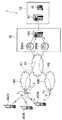
図1は、本実施形態に係る通信システム1の全体概略構成図である。図1に示すように、通信システム1には、無線IPネットワーク10A及び無線IPネットワーク10Bが含まれる。無線IPネットワーク10Aは、IPパケットを伝送することができるIPネットワークである。
(Overall schematic configuration of communication system)
FIG. 1 is an overall schematic configuration diagram of a communication system 1 according to the present embodiment. As shown in FIG. 1, the communication system 1 includes a
無線IPネットワーク10Aは、携帯電話端末300A,300B及び300N(無線通信装置)との無線通信を実行する無線基地局11,12を備える。本実施形態では、無線IPネットワーク10Aは、無線通信方式としてCDMA(具体的には、3GPP2の規格であるHRPD)を用いる携帯電話ネットワークである。
The
無線IPネットワーク10Bは、無線IPネットワーク10Aと同様にIPパケットを伝送することができる。無線IPネットワーク10Bは、携帯電話端末300A,300B及び300N(無線通信装置)との無線通信を実行する無線基地局13を備える。なお、無線基地局及び携帯電話端末の数は、図1に示した数に限定されるものではない。
The wireless IP network 10B can transmit IP packets in the same manner as the
無線IPネットワーク10Bは、無線IPネットワーク10Aとは異なる無線通信方式を用いる。本実施形態では、無線IPネットワーク10Bは、無線通信方式として、IEEE802.16eの規定に準拠したモバイルWiMAXを用いる。
The wireless IP network 10B uses a wireless communication method different from that of the
また、無線IPネットワーク10A及び無線IPネットワーク10Bでは、音声信号がIPパケットに変換されたVoIPパケット(音声IPパケット)が伝送される。なお、CDMAを用いる無線IPネットワーク10Aと、モバイルWiMAXを用いる無線IPネットワーク10Bとは、音声信号の符号化に用いられる音声符号化則が異なる。具体的には、無線IPネットワーク10Aでは、ITU−T G.729が用いられる。また、無線IPネットワーク10Bでは、ITU−T G.711が用いられる。
Further, in the
無線IPネットワーク10A及び無線IPネットワーク10Bは、インターネット20に接続される。また、インターネット20には、中継センタ30が接続される。
The
中継センタ30には、携帯電話端末300A,300B及び300Nが送受信するIPパケットを中継するネットワーク機器が設置される。具体的には、中継センタ30には、スイッチングサーバ100、及びVPNルータ200A,200Bが設置される。
The
スイッチングサーバ100は、携帯電話端末300A,300B及び300Nとの通信経路(通信経路R1,R2)を制御する。本実施形態において、スイッチングサーバ100は、通信経路制御装置を構成する。
The switching
VPNルータ200A,200Bは、IPパケットのルーティング処理を実行する。また、VPNルータ200A,200Bは、携帯電話端末300A(300B,300N)〜スイッチングサーバ100間に、VPN(IPSec)によるトンネルを確立する。当該トンネルを確立することによって、OSI第3層の仮想化を実現し、携帯電話端末300A(300B,300N)のIPモビリティが確保される。
The
すなわち、本実施形態では、Mobile IP(RFC2002)とは異なり、携帯電話端末300A(300B,300N)は、無線IPネットワーク10Aを経由して設定された通信経路R1、及び無線IPネットワーク10Bを経由して設定された通信経路R2の両通信経路を同時に用いながら、通信先(具体的には、IP電話端末42)との通信を実行することができる。
That is, in this embodiment, unlike Mobile IP (RFC2002), the
つまり、携帯電話端末300A(300B,300N)は、スイッチングサーバ100を経由して通信先との通信を実行するが、通信先は、携帯電話端末300A(300B,300N)〜スイッチングサーバ100間において、通信経路R1または通信経路R2の何れの通信経路が用いられているかを認識せずに、携帯電話端末300A(300B,300N)のホームアドレスを宛先アドレスとして用いることができる。なお、本実施形態では、スイッチングサーバ100において、携帯電話端末300A(300B,300N)のホームアドレスは、無線IPネットワーク10Aにおいて携帯電話端末300A(300B,300N)に割り当てられる気付アドレス、及び無線IPネットワーク10Bにおいて携帯電話端末300A(300B,300N)に割り当てられる気付アドレスとそれぞれ対応付けられる。
That is, the
中継センタ30(スイッチングサーバ100)は、所定の通信ネットワーク(不図示)を経由して、ユーザ構内40と接続される。ユーザ構内40には、IP電話交換機41及びIP電話端末42が設置される。IP電話交換機41は、当該所定の通信ネットワークとIP電話端末42との間においてVoIPパケットを中継する。IP電話端末42は、音声信号とVoIPパケットとを相互に変換したり、VoIPパケットを送受信したりする。
The relay center 30 (switching server 100) is connected to the
(通信システムの機能ブロック構成)
次に、通信システム1の機能ブロック構成について説明する。具体的には、通信システム1に含まれるスイッチングサーバ100及び携帯電話端末300Aの機能ブロック構成について説明する。
(Functional block configuration of communication system)
Next, the functional block configuration of the communication system 1 will be described. Specifically, functional block configurations of the switching
なお、以下の説明では、スイッチングサーバ100、携帯電話端末300A(300B,300N)、及びユーザ構内40に設置されるIP電話交換機41,IP電話端末42をそれぞれ次のように適宜省略する。
In the following description, the switching
・ スイッチングサーバ100: SS
・ 携帯電話端末300A(300B,300N): MN
・ IP電話交換機41,IP電話端末42: CN
(1)スイッチングサーバ100
図2は、スイッチングサーバ100の機能ブロック構成図である。図2に示すように、スイッチングサーバ100は、通信インタフェースとして、MN側通信インタフェース101、MN側通信インタフェース103及びCN側通信インタフェース123を備える。
-Switching server 100: SS
・
(1)
FIG. 2 is a functional block configuration diagram of the switching
MN側通信インタフェース101,103は、MNとの通信の実行に用いられる。具体的には、MN側通信インタフェース101は、VPNルータ200Aと接続され、MN側通信インタフェース103は、VPNルータ200Bと接続される。CN側通信インタフェース123は、CNとの通信の実行に用いられる。
The MN side communication interfaces 101 and 103 are used to execute communication with the MN. Specifically, the MN
また、スイッチングサーバ100は、擬似パケット生成部105、無音検出部107、送信パケット振り分け部109、通信経路制御部111、MN側受信制御部113、CN側受信制御部115、CN側送信部117、CN側通信経路制御部119及びタイマ121を備える。
The switching
擬似パケット生成部105は、後述する擬似パケット生成部311と同様に、無音検出部107によってVoIPパケットの送信が停止されている間、VoIPパケットの擬似パケットを所定の間隔で送信することができる。
The pseudo
無音検出部107は、CN側受信制御部115を介してCNから受信したVoIPパケットの受信時刻に基づいて、携帯電話端末300Aと、通信先であるIP電話端末42との間における通話(下り方向)が行われていない状態(無音状態)を検出する。
具体的には、無音検出部107は、既にCNから受信したVoIPパケットの平均受信間隔と、最新のVoIPパケットの受信間隔とに基づいて、CNによるVoIPパケットの送信が停止されているか否かを判定する。なお、最新のVoIPパケットの受信間隔とは、最後に受信したVoIPパケットと、当該VoIPパケットの直前に受信したVoIPパケットとの間隔である。
Specifically, the
本実施形態では、無音検出部107は、表1及び表2に示す条件にしたがって無音状態を判定する。

なお、表1及び表2に示す無音状態の判定方法は例示であり、公知の他の方法に基づく判定方法でも構わない。また、携帯電話端末300Aの通話者がしゃべっているために、下り方向、つまり、IP電話端末42からスイッチングサーバ100への方向において、無音状態が数秒以上に渡って継続するような場合、通信経路(例えば、通信経路R1)が切断されていないことを、RTCPパケットを用いて検出してもよい。或いは、CN側受信制御部115がVoIPパケットを1秒以上受信しない場合、比較的パケットサイズの小さいICMPパケット(ping)を用いて通信経路が切断されていないことを能動的に確認するようにしてもよい。
In addition, the determination method of the silent state shown in Table 1 and Table 2 is an exemplification, and a determination method based on another known method may be used. In addition, when the caller of the
さらに、無音検出部107は、下り方向に加え、MNから受信したVoIPパケットに基づいて、上り方向の無音状態を検出することもできる。
Furthermore, the
送信パケット振り分け部109は、通信経路制御部111による指示に応じて、携帯電話端末300Aに送信されるIPパケットをMN側通信インタフェース101またはMN側通信インタフェース103の何れかに振り分ける。また、送信パケット振り分け部109は、携帯電話端末300Aに送信されるIPパケットに、携帯電話端末300Aのホームアドレスと対応付けられている気付アドレスを付加する。
The transmission
通信経路制御部111は、携帯電話端末300Aに送信されるIPパケットの通信経路を選択する。具体的には、通信経路制御部111は、携帯電話端末300Aに送信されるIPパケットの通信経路として、通信経路R1または通信経路R2(図1参照)を選択する。
The communication path control unit 111 selects a communication path of an IP packet transmitted to the
また、通信経路制御部111は、MN側受信制御部113が取得した複数のVoIPパケットの受信時刻に基づいて、例えば、通信経路を無線IPネットワーク10A経由から、無線IPネットワーク10B経由に切り替える。
Also, the communication path control unit 111 switches the communication path from, for example, the
具体的には、通信経路制御部111は、タイマ121によって出力されるデータを用い、受信したVoIPパケットの受信時刻に基づいて所定の基準時刻(例えば、図7に示す時刻t0)からの経過時間を演算する。通信経路制御部111は、VoIPパケットに含まれる当該VoIPパケットのシーケンス番号(seq)、及びVoIPパケットの時間長(例えば、20ms)を用いて求められる標準伝送時間と、演算した経過時間との差に基づいて、例えば、通信経路R1を通信経路R2に切り替える。また、通信経路制御部111は、通信経路の切り替え要求をMNに送信する。
Specifically, the communication path control unit 111 uses the data output by the
また、通信経路制御部111は、無音検出部107によってVoIPパケットの送信が停止されていると判定されている間、通信経路の切り替えを中止することができる。
Further, the communication path control unit 111 can cancel the switching of the communication path while the
さらに、通信経路制御部111は、同一の無線基地局(例えば、無線基地局11)との無線通信を実行する複数の移動電話端末(例えば、携帯電話端末300A,300B及び300N)との通信経路を切り替える場合、当該複数の移動電話端末のうち、一部の移動電話端末(例えば、携帯電話端末300A)との通信経路のみを切り替えることができる。通信経路制御部111は、当該一部の移動電話端末との通信経路の切り替えが完了した後、MN側受信制御部113が取得した複数のVoIPパケットの受信時刻に基づいて、当該一部の移動電話端末を除く残りの移動電話端末(携帯電話端末300B,300N)との通信経路を切り替えるか否かを判定する。
Further, the communication path control unit 111 communicates with a plurality of mobile telephone terminals (for example,
本実施形態では、通信経路制御部111は、表3及び表4に示す条件にしたがって通信経路を切り替えるか否かを判定する。
なお、本実施形態では、20msのフレーム長を使用したコーデック(音声符号化則)が用いられるため、シーケンス番号(seq)*20msを基準としているが、フレーム長が30msの場合は、シーケンス番号(seq)*30msを基準とすればよい。 In this embodiment, since a codec (speech coding rule) using a frame length of 20 ms is used, the sequence number (seq) * 20 ms is used as a reference. However, when the frame length is 30 ms, the sequence number ( seq) * 30 ms may be used as a reference.
MN側受信制御部113は、携帯電話端末300Aから受信したIPパケットに関する制御を実行する。特に、本実施形態では、MN側受信制御部113は、MN側通信インタフェース101またはMN側通信インタフェース103を介して受信したVoIPパケットの受信時刻を順次取得する。本実施形態において、MN側受信制御部113は、受信時刻取得部を構成する。また、MN側受信制御部113は、携帯電話端末300Aから受信したVoIPパケットをCN側通信経路制御部119に中継する。
The MN side
CN側受信制御部115は、IP電話交換機41から受信したIPパケットに関する制御を実行する。特に、本実施形態では、CN側受信制御部115は、CN側通信インタフェース123を介して受信したVoIPパケットの受信時刻を順次取得することができる。また、CN側受信制御部115は、IP電話交換機41から受信したVoIPパケットを送信パケット振り分け部109に中継する。
The CN side
CN側送信部117は、CN側通信経路制御部119から出力されたIPパケットをCN側通信インタフェース123に中継する。
The CN
CN側通信経路制御部119は、MN側受信制御部113によって中継されたIPパケットに含まれる宛先アドレスに基づいて、CNに向けて送信されるIPパケットの通信経路を制御する。本実施形態では、MN側受信制御部113とCN側通信経路制御部119とによって、携帯電話端末300Aから通信先に向けて送信されたVoIPパケットを中継する中継部が構成される。
The CN side communication
タイマ121は、通信経路制御部111による経過時間の演算に用いられる時間情報を出力する。
The
(2)携帯電話端末300A
図3は、携帯電話端末300Aの機能ブロック構成図である。なお、携帯電話端末300B,300Nも携帯電話端末300Aと同様の機能ブロック構成を有する。また、以下、上述したスイッチングサーバ100と同様の機能については、その説明を適宜省略する。
(2)
FIG. 3 is a functional block configuration diagram of the
図3に示すように、携帯電話端末300Aは、無線通信インタフェース301及び無線通信インタフェース303を備える。無線通信インタフェース301は、無線IPネットワーク10Aを経由する通信に用いられる。すなわち、無線通信インタフェース301は、CDMA(3GPP2の規格であるHRPD)の規格に準拠している。
As shown in FIG. 3, the mobile phone terminal 300 </ b> A includes a
無線通信インタフェース303は、無線IPネットワーク10Bを経由する通信に用いられる。すなわち、無線通信インタフェース303は、モバイルWiMAXの規格に準拠している。
The
また、携帯電話端末300Aは、無線状態監視部305、受信制御部307、送信パケット振り分け部309、擬似パケット生成部311、アプリケーション313、無音検出部315、ユーザインタフェース317、通信経路制御部319及びタイマ321を備える。
In addition, the
無線状態監視部305は、無線通信インタフェース301及び無線通信インタフェース303が受信する無線信号の状態を監視する。
The wireless
また、無線状態監視部305は、スイッチングサーバ100からの指示に基づいて、無線通信インタフェース301または無線通信インタフェース303を介して、無線IPネットワーク10Aまたは無線IPネットワーク10Bの状態(例えば、RSSI)を測定し、測定した結果をスイッチングサーバ100に通知することができる。さらに、無線状態監視部305は、無線通信インタフェース301及び無線通信インタフェース303と対向する無線基地局の識別子をスイッチングサーバ100に通知することもできる。
Further, the wireless
受信制御部307は、スイッチングサーバ100から受信したIPパケットに関する制御を実行する。特に、本実施形態では、受信制御部307は、無線通信インタフェース301または無線通信インタフェース303を介して受信したVoIPパケットの受信時刻を順次取得する。また、受信制御部307は、スイッチングサーバ100から受信したVoIPパケットをアプリケーション313に中継する。
The
送信パケット振り分け部309は、スイッチングサーバ100に送信されるIPパケットを無線通信インタフェース301または無線通信インタフェース303の何れかに振り分ける。なお、本実施形態では、受信制御部307と、送信パケット振り分け部309とによって、送受信部が構成される。
The transmission
擬似パケット生成部311は、無音検出部315によってVoIPパケットの送信を停止されていると判定されている間、当該停止まで送信パケット振り分け部309がVoIPパケットを送信していた無線IPネットワーク(例えば、無線IPネットワーク10A)を経由して、VoIPパケットの擬似パケットを所定の間隔で送信することができる。本実施形態では、送信パケット振り分け部309と、擬似パケット生成部311とによって、擬似パケット送信部が構成される。
While it is determined by the
具体的には、擬似パケット生成部311は、無音検出部315によってVoIPパケットの送信が停止されている間、VoIPパケットと宛先アドレス及び送信タイミングが同様な擬似パケットを生成し、送信パケット振り分け部309に出力する。
Specifically, the pseudo
アプリケーション313は、携帯電話端末300Aの機能を提供するために必要となる各種のアプリケーションソフトウェア(例えば、IP電話)によって構成される。アプリケーション313に含まれるIP電話アプリケーションによって、音声信号とVoIPパケットとの相互変換が実行される。また、IP電話アプリケーションは、ユーザインタフェース317を介して音声信号が入力されないとき(具体的には、入力される音声信号が所定のレベル以下のとき)に、VoIPパケットの送信を停止する。
The
無音検出部315は、アプリケーション313(IP電話)によってVoIPパケットが生成されない場合、つまり、VoIPパケットが所定の間隔で送信されているか否かを検出する。なお、アプリケーション313(IP電話)は、ユーザインタフェース317を介して音声信号(またはVoIPパケット)が入力されていないとき、VoIPパケットを生成しないようにすることができる。
The
本実施形態では、無音検出部315は、スイッチングサーバ100と同様に、表1に示した無音状態判定閾値に基づいて無音状態を判定する。ここで、図7は、無音検出部315による無音状態の判定処理、及び擬似パケット生成部311による擬似パケットの送信処理の具体例を示す。
In the present embodiment, the
図7に示すように、VoIPパケット(より具体的には、RTPパケット)は、20msごとに送信される。VoIPパケットのサイズは65byteである。図7では、VoIPパケットP11が時刻t0に送信され、次いで、VoIPパケットP12及びP13が20msごとに順次送信されている。ここで、無音検出部315は、時刻t1に無音状態を検出する。
As shown in FIG. 7, VoIP packets (more specifically, RTP packets) are transmitted every 20 ms. The size of the VoIP packet is 65 bytes. In FIG. 7, VoIP packet P11 is transmitted at time t0, and then VoIP packets P12 and P13 are sequentially transmitted every 20 ms. Here, the
無音検出部315によって無音状態が検出されると、擬似パケット生成部311は、擬似パケットP21を時刻t2に送信する。なお、擬似パケット生成部311は、VoIPパケットの送信周期と合わせて時刻t2’に擬似パケットP21を送信してもよいが、本実施形態では、所定の閾値(5ms)の経過後(時刻t2)に、擬似パケットP21を送信する。
When the
また、擬似パケット生成部311は、HPRDの送信周期(所定の無線フレーム)に合わせて擬似パケットを送信する。本実施形態では、VoIPパケットの送信周期は20msであり、HPRDの送信周期は26.6msである。
Further, the
なお、無音検出部315によって無音状態と判定された後、最初に送信される擬似パケットP21の送信タイミングは、次のHPRDの送信周期にしたがって送信される121byteの無線パケット(不図示)に含まれていればよく、図7の例の場合、所定の閾値(5ms)を15msまで延ばすこともできる。
Note that the transmission timing of the first pseudo packet P21 transmitted after the
また、本実施形態では、無線IPネットワーク10Aを介して送信されるVoIPパケットは、HPRDの送信周期、つまり、所定の無線フレームに割り当てられる。また、無線フレームの構成は、無線IPネットワーク10Aと、無線IPネットワーク10Bとにおいて異なる。
In this embodiment, a VoIP packet transmitted via the
擬似パケット生成部311は、擬似パケットP21〜P2nを順次送信する。なお、擬似パケットP21〜P2nは、上述したように、VoIPパケットP11〜P13とほぼ同様の構成を有する。
The pseudo
次いで、無音検出部315は、時刻t3にVoIPパケットP14の送信を検出する。無音検出部315によってVoIPパケットP14の送信が検出されると、擬似パケット生成部311は、擬似パケットの送信を中止する。また、VoIPパケットP14に引き続き、VoIPパケットP15,P16が送信される。
Next, the
図3に示すように、ユーザインタフェース317は、携帯電話端末300Aのユーザとのインタフェースを提供する。ユーザインタフェース317には、操作キー部や画像表示部が含まれる。また、ユーザインタフェース317には、パーソナル・コンピュータなどを接続する通信インタフェースも含まれる。
As shown in FIG. 3, the
通信経路制御部319は、無線状態監視部305によって監視された無線信号の状態や、受信制御部307によって取得されたVoIPパケットの受信時刻に基づいて、例えば、通信経路を無線IPネットワーク10A経由から、無線IPネットワーク10B経由に切り替える。
Based on the state of the wireless signal monitored by the wireless
タイマ321は、通信経路制御部319による通信経路の切り替えの判定などに用いられる時間情報を出力する。
The
(通信システムの動作)
次に、上述した通信システム1の動作について説明する。具体的には、(1)通信経路の切り替え動作、(2)擬似パケットの送信動作、(3)複数の携帯電話端末との通信経路の順次切り替え動作、について説明する。
(Operation of communication system)
Next, the operation of the communication system 1 described above will be described. Specifically, (1) communication path switching operation, (2) pseudo packet transmission operation, and (3) sequential switching operation of communication paths with a plurality of mobile phone terminals will be described.
(1)通信経路の切り替え動作
図4は、スイッチングサーバ100による通信経路の切り替え動作を示すフロー図である。図4に示すように、ステップS11において、スイッチングサーバ100(SS)は、MN(例えば、携帯電話端末300A)とCN(IP電話端末42)との通信(音声通話)の開始に伴って、MN及びCNから、VoIPパケットをそれぞれ受信する。なお、ステップS11では、通信経路R1、つまり、無線IPネットワーク10A(図1参照)を用いて通信が開始されたものとする。
(1) Communication Path Switching Operation FIG. 4 is a flowchart showing the communication path switching operation by the switching
ステップS13において、スイッチングサーバ100は、通信の開始に伴い、シーケンス番号(seq)が0であるVoIPパケットを受信すると、当該VoIPパケットの受信時刻(例えば、時刻t0)からの経過時間(t)の計測を開始する。
In step S13, when the switching
ステップS15において、スイッチングサーバ100は、順次受信したVoIPパケットのシーケンス番号(seq)及び当該VoIPパケットの受信時刻を監視する。
In step S15, the switching
ステップS17において、スイッチングサーバ100は、無音状態を検出したか否かを判定する。具体的には、スイッチングサーバ100は、表1及び表2に示した条件にしたがって、MNとCNとの通信(音声通話)が、無音状態か否かを判定する。
In step S17, the switching
無音状態を検出した場合(ステップS17のYES)、スイッチングサーバ100は、ステップS13からの動作を繰り返す。
When the silent state is detected (YES in step S17), the switching
無音状態を検出していない場合(ステップS17のNO)、ステップS19において、スイッチングサーバ100は、通信経路の切り替え条件を満足するか否かを判定する。具体的には、スイッチングサーバ100は、表3及び表4に示した条件にしたがって、通信経路の切り替え条件を満足するか否かを判定する。
When the silent state is not detected (NO in step S17), in step S19, the switching
通信経路の切り替え条件を満足する場合(ステップS19のYES)、ステップS21において、スイッチングサーバ100は、MNとの通信経路を切り替える。具体的には、スイッチングサーバ100は、通信経路R1から通信経路R2に切り替える。
When the communication path switching condition is satisfied (YES in step S19), in step S21, the switching
通信経路の切り替え条件を満足しない場合(ステップS19のNO)、スイッチングサーバ100は、ステップS15からの動作を繰り返す。
If the communication path switching condition is not satisfied (NO in step S19), the switching
ステップS23において、スイッチングサーバ100は、通信経路を通信経路R1から通信経路R2に切り替える切り替え要求をMNに送信する。
In step S23, the switching
ステップS21及びS23の動作が完了すると、MNとCNとの間において送受信されるVoIPパケットは、通信経路R1ではなく、通信経路R2経由に変更される。 When the operations in steps S21 and S23 are completed, the VoIP packet transmitted / received between the MN and the CN is changed to the communication path R2 instead of the communication path R1.
(2)擬似パケットの送信動作
図5は、携帯電話端末300Aによる擬似パケットの送信動作を示すフロー図である。図5に示すように、ステップS101において、携帯電話端末300A(MN)は、SSを介してCNに送信されるVoIPパケットを監視する。具体的には、携帯電話端末300Aは、CNに送信されるVoIPパケットの送信時刻を監視する。なお、ここでは、通信経路R1を用いてVoIPパケットが送信されるものとする。
(2) Pseudo Packet Transmission Operation FIG. 5 is a flowchart showing a pseudo packet transmission operation by the
ステップS103において、携帯電話端末300Aは、最近に送信されたVoIPパケットの送信時刻から所定時間(例えば、表1に示す無音状態判定閾値)経過したか否かを判定する。
In step S103, the
最近に送信されたVoIPパケットの送信時刻から所定時間経過した場合(ステップS103のYES)、携帯電話端末300Aは、ステップS105A〜S105Bのループ処理を20msごとに実行する。
When a predetermined time has elapsed from the transmission time of the recently transmitted VoIP packet (YES in step S103), the
ステップS107において、携帯電話端末300Aは、CNにVoIPパケットを送信したか否かを判定する。
In step S107, the
CNにVoIPパケットを送信していない場合(ステップS107のNO)、ステップS109において、携帯電話端末300Aは、擬似パケットを送信する。例えば、図7に示すように、携帯電話端末300Aは、通信経路R1、つまり、VoIPパケットが送信されていた通信経路と同一の通信経路を用いて、擬似パケットP21をSSに送信する。
When the VoIP packet is not transmitted to the CN (NO in step S107), in step S109, the
SSにVoIPパケットを送信した場合(ステップS107のYES)、ステップS111において、携帯電話端末300Aは、擬似パケットの送信を中止する。
When the VoIP packet is transmitted to the SS (YES in step S107), in step S111, the
(3)複数の携帯電話端末との通信経路の順次切り替え動作
図6は、複数の携帯電話端末との通信経路を順次切り替える動作を示すフロー図である。ここでは、複数のMN、具体的には、携帯電話端末300A,300B及び300Nが同一の無線基地局、具体的には、無線基地局11と無線通信を実行しているものとする。
(3) Operation for sequentially switching communication paths with a plurality of mobile phone terminals FIG. 6 is a flowchart showing an operation for sequentially switching communication paths with a plurality of mobile phone terminals. Here, it is assumed that a plurality of MNs, specifically,
図6に示すように、ステップS201において、スイッチングサーバ100(SS)は、各MNから送信されたVoIPパケットの受信間隔を監視する。具体的には、スイッチングサーバ100は、各MNから送信されるVoIPパケットの受信時刻に基づいて、VoIPパケットの受信間隔を監視する。また、スイッチングサーバ100は、各MNが無線通信を実行している無線基地局11の識別子を取得する。なお、当該識別子は、例えば、各MNから送信されるIPパケットに含めることができる。
As shown in FIG. 6, in step S201, the switching server 100 (SS) monitors the reception interval of VoIP packets transmitted from each MN. Specifically, the switching
ステップS203において、スイッチングサーバ100は、何れかのMN(例えば、携帯電話端末300A)から送信されたVoIPパケットの受信間隔が、通信経路の切り替え条件(表3及び表4参照)を満足するか否かを判定する。
In step S203, the switching
当該条件を満足する場合(ステップS203のYES)、ステップS205において、スイッチングサーバ100は、当該条件を満足するVoIPパケットを送信したMN(携帯電話端末300A)と同一基地局(無線基地局11)を介して接続されている他のMNから送信されたVoIPパケットの受信間隔が、ステップS203において当該条件を満足すると判定されたMN(携帯電話端末300A)と同様に、通信経路の切り替え条件を満足するか否かを判定する。
If the condition is satisfied (YES in step S203), in step S205, the switching
一方、当該条件を満足しない場合(ステップS203のNO)、スイッチングサーバ100は、ステップS201からの動作を繰り返す。
On the other hand, when the condition is not satisfied (NO in step S203), the switching
他のMNも同様に当該条件を満足する場合(ステップS205のYES)、ステップS207において、スイッチングサーバ100は、当該条件を満足する複数のMNに、通信経路の切り替え先(無線IPネットワーク10B)の状態(例えば、RSSIやCIR)の測定(測定結果の通知を含む)を指示する。
Similarly, when other MNs also satisfy the condition (YES in step S205), in step S207, the switching
つまり、本実施形態では、同一の無線基地局を介して接続される複数のMNについて、VoIPパケットの受信間隔が同様である場合、無線区間の状態の変化に伴って上り方向の通信品質が劣化したのではなく、トラフィックの混雑によるものと推定される。 That is, in this embodiment, when the reception interval of VoIP packets is the same for a plurality of MNs connected via the same radio base station, the communication quality in the uplink direction deteriorates as the state of the radio section changes. Rather than that, it is estimated that it is due to traffic congestion.
他のMNは当該条件を満足しない場合(ステップS205のNO)、ステップS209において、スイッチングサーバ100は、ステップS203において当該条件を満足すると判定されたMNとの通信経路を切り替える。なお、具体的な切り替え方法は、上述したステップS21及びS23と同様である。
When the other MN does not satisfy the condition (NO in step S205), in step S209, the switching
ステップS211において、スイッチングサーバ100は、各MNからの通知された切り替え先(無線IPネットワーク10B)の状態の測定結果に基づいて、切り替え先の状態が最も良好なMN(例えば、携帯電話端末300A)との通信経路を切り替える。具体的には、スイッチングサーバ100は、切り替え先の状態が最も良好なMN(携帯電話端末300A)との通信経路R1(無線IPネットワーク10A経由)を、通信経路R2(無線IPネットワーク10B経由)に切り替える。
In step S211, the switching
ステップS213において、スイッチングサーバ100は、通信経路を切り替えていない他のMN(携帯電話端末300B,300N)から送信されたVoIPパケットの受信間隔が改善したか否かを判定する。具体的には、スイッチングサーバ100は、当該MNから送信されたVoIPパケットの受信間隔が、通信経路の切り替え条件を満足しないようになったかを判定する。
In step S213, the switching
ここで、仮に、すべてのMNとの通信経路を一斉に切り替えた場合、切り替え先でのトラフィックが急激に増大し、切り替え先でも同様の状態が発生する可能性がある。そこで、一部のMNを対象として通信経路を切り替えれば、それぞれの無線IPネットワークにトラフィックが分散され、通信経路を切り替えていない他のMNについても通信品質を改善させられる可能性があるためである。 Here, if the communication paths with all the MNs are switched at the same time, traffic at the switching destination increases rapidly, and a similar state may occur at the switching destination. Therefore, if communication routes are switched for some MNs, traffic is distributed to each wireless IP network, and communication quality may be improved for other MNs that have not switched communication routes. .
当該MNから送信されたVoIPパケットの受信間隔が改善した場合(ステップS213のYES)、スイッチングサーバ100は、ステップS201からの動作を繰り返す。つまり、スイッチングサーバ100は、当該MNとの通信経路を切り替えない。
When the reception interval of the VoIP packet transmitted from the MN is improved (YES in step S213), the switching
一方、当該MNから送信されたVoIPパケットの受信間隔が改善しない場合(ステップS213のNO)、スイッチングサーバ100は、ステップS211からの動作を繰り返す。つまり、スイッチングサーバ100は、当該MN(携帯電話端末300B,300N)のうち、切り替え先の状態が最も良好なMN(例えば、携帯電話端末300B)との通信経路R1(無線IPネットワーク10A経由)を、通信経路R2(無線IPネットワーク10B経由)に切り替える。
On the other hand, when the reception interval of the VoIP packet transmitted from the MN is not improved (NO in step S213), the switching
(作用・効果)
スイッチングサーバ100によれば、MNからCNに向けて送信された複数のVoIPパケットの受信時刻に基づいて、通信経路が、通信経路R1から通信経路R2に切り替えられる。このため、無線IPネットワーク10A(または無線IPネットワーク10B)の上り方向における通信品質(ジッタ)の劣化した場合でも、通信経路を切り替えることができる。
(Action / Effect)
According to the switching
また、スイッチングサーバ100によれば、音声信号がIPパケットに変換されたVoIPパケットの受信時刻に基づいて通信経路を切り替えるか否かが即座に判定されるため、平均的な送信間隔が長いRTCPパケットなどを用いる場合と比較して、通信品質の劣化に迅速に対応することができる。すなわち、スイッチングサーバ100によれば、フェージングなど、急激な通信品質の劣化が生じ得る無線IPネットワーク10A,10Bにも対応することができる。
Moreover, according to the switching
スイッチングサーバ100によれば、スイッチングサーバ100が受信したVoIPパケットのシーケンス番号(seq)及びVoIPパケットの時間長(20ms)を用いて求められる標準伝送時間と、所定の基準時刻(例えば、図10に示した時刻t0)から経過時間との差に基づいて、通信経路を切り替えるか否かが判定される。すなわち、無音状態が検出された場合などには、適宜所定の基準時刻が設定し直され(図4のステップS13参照)、通信経路の切り替えの判定に用いる範囲が変更されるため、通信経路を切り替えるか否かの判定精度を高めることができる。
According to the switching
なお、スイッチングサーバ100は、MNからCNに向けて送信された複数のVoIPパケットについて、バッファリングせずにジッタを測定するのみであるため、VoIPパケットの伝送遅延は増大しない。
Note that the switching
また、スイッチングサーバ100によれば、同一の無線基地局との無線通信を実行する複数のMN(携帯電話端末300A,300B及び300N)の通信経路を切り替える場合、まず、一部のMN(例えば、携帯電話端末300A)との通信経路のみが切り替えられる(図6のステップS211参照)。さらに、当該一部のMNとの通信経路が切り替えると、当該一部のMNを除く残りのMN(携帯電話端末300B,300N)との通信経路を切り替えるか否かが判定される。
Further, according to the switching
このため、特定の無線基地局(例えば、無線基地局11)において、トラフィックの増大によって上り方向の通信品質が劣化した場合でも、切り替え先の無線IPネットワークに含まれる無線基地局(例えば、無線基地局13)が処理すべきトラフィックが急激に増大することを回避できる。 For this reason, in a specific radio base station (for example, the radio base station 11), even when the communication quality in the uplink direction is deteriorated due to an increase in traffic, the radio base station (for example, the radio base station) included in the switching destination radio IP network It is possible to avoid a sudden increase in traffic to be processed by the station 13).
また、通信システム1(例えば、スイッチングサーバ100または携帯電話端末300A)によれば、無音状態を検出することができるため、無音状態を含めてVoIPパケットの受信間隔を判定することを回避できる。また、携帯電話端末300Aによれば、無音状態のときには擬似パケットを送信することができる。このため、VoIPパケットの受信間隔、つまり、通信品質(ジッタ)をより正確に判定することができる。
In addition, according to the communication system 1 (for example, the switching
さらに、本実施形態では、図7に示したように、所定の閾値(5ms)の経過後(時刻t2)に、擬似パケットP21が送信される。当該閾値が、スイッチングサーバ100での通信経路切り替え判定閾値(表3参照)と比較して十分に小さければ、スイッチングサーバ100は、通信経路切り替え判定閾値に到達する前に擬似パケットP21を受信する。このため、スイッチングサーバ100は、無音状態であることを判定できる。また、スイッチングサーバ100は、擬似パケットを受信すると、上述したように所定の基準時刻(時刻t0)を設定し直すため、通信経路を切り替えるか否かの判定精度を高めることができる。
Furthermore, in the present embodiment, as illustrated in FIG. 7, the pseudo packet P21 is transmitted after a predetermined threshold (5 ms) has elapsed (time t2). If the threshold is sufficiently smaller than the communication path switching determination threshold (see Table 3) in the switching
一方、当該所定の閾値を長くし過ぎた場合、スイッチングサーバ100は、擬似パケットを適当なタイミングで受信できず、通信経路切り替え判定閾値に基づいて通信経路を切り替える。しかしながら、スイッチングサーバ100は、当該擬似パケットを受信次第、通信経路を切り替え前の状態に戻すこともできる。
On the other hand, if the predetermined threshold is too long, the switching
(その他の実施形態)
上述したように、本発明の一実施形態を通じて本発明の内容を開示したが、この開示の一部をなす論述及び図面は、本発明を限定するものであると理解すべきではない。この開示から当業者には様々な代替実施の形態が明らかとなろう。
(Other embodiments)
As described above, the content of the present invention has been disclosed through one embodiment of the present invention. However, it should not be understood that the description and drawings constituting a part of this disclosure limit the present invention. From this disclosure, various alternative embodiments will be apparent to those skilled in the art.
例えば、上述した実施形態では、スイッチングサーバ100において通信経路を切り替えるか否かを判定する形態としたが、携帯電話端末300Aが、スイッチングサーバ100から受信したVoIPパケットの受信間隔に基づいて、通信経路の切り替えを判定してもよい。この場合、携帯電話端末300Aは、無線通信の状態(例えば、RSSIやCIR)を含めて通信経路を切り替えるか否かを判定してもよい。
For example, in the above-described embodiment, the switching
また、スイッチングサーバ100は、アプリケーションを特定するアプリケーション情報を取得して、取得したアプリケーション情報に応じて無音状態判定閾値(表1)や判定条件(表2)を変更してもよい。なお、アプリケーションとしては、IP電話アプリケーションやIPTVアプリケーションなどが挙げられる。
Moreover, the switching
また、上述した実施形態では、携帯電話端末300A(300B,300N)を例として説明したが、携帯電話端末300Aに代えて、無線通信カードと、IP電話アプリケーションソフトウェア(いわゆるソフトフォン)を実装したパーソナル・コンピュータなどとを用いてもよい。
In the above-described embodiment, the
このように、本発明は、ここでは記載していない様々な実施の形態などを含むことは勿論である。したがって、本発明の技術的範囲は、上述の説明から妥当な特許請求の範囲に係る発明特定事項によってのみ定められるものである。 As described above, the present invention naturally includes various embodiments that are not described herein. Therefore, the technical scope of the present invention is defined only by the invention specifying matters according to the scope of claims reasonable from the above description.
1…通信システム、10A,10B…無線IPネットワーク、20…インターネット、11〜13…無線基地局、30…中継センタ、40…ユーザ構内、41…IP電話交換機、42…IP電話端末、100…スイッチングサーバ、101,103…MN側通信インタフェース、105…擬似パケット生成部、107…無音検出部、109…送信パケット振り分け部、111…通信経路制御部、113…MN側受信制御部、115…CN側受信制御部、117…CN側送信部、119…CN側通信経路制御部、121…タイマ、123…CN側通信インタフェース、200A,200B…VPNルータ、300A,300B,300N…携帯電話端末、301,303…無線通信インタフェース、305…無線状態監視部、307…受信制御部、309…送信パケット振り分け部、311…擬似パケット生成部、313…アプリケーション、315…無音検出部、317…ユーザインタフェース、319…通信経路制御部、321…タイマ、P11〜P16…VoIPパケット、P21〜P2n…擬似パケット、R1,R2…通信経路
DESCRIPTION OF SYMBOLS 1 ... Communication system, 10A, 10B ... Wireless IP network, 20 ... Internet, 11-13 ... Wireless base station, 30 ... Relay center, 40 ... User premises, 41 ... IP telephone exchange, 42 ... IP telephone terminal, 100 ...
Claims (1)
前記無線通信装置から通信先に向けて送信された前記音声IPパケットを中継する中継部と、
前記中継部が受信した受信音声IPパケットの受信時刻を順次取得する受信時刻取得部と、
前記受信時刻取得部が取得した複数の前記受信時刻に基づいて、前記通信経路を前記第1の無線IPネットワーク経由から、前記第2の無線IPネットワーク経由に切り替える通信経路制御部と、を備え
前記第1の無線IPネットワークは、前記無線通信装置との無線通信を実行する複数の無線基地局を備え、
前記通信経路制御部は、同一の無線基地局との無線通信を実行する複数の無線通信装置との前記通信経路を切り替える場合、前記複数の無線通信装置のうち、一部の無線通信装置との前記通信経路を切り替え、
前記一部の無線通信装置との前記通信経路の切り替えが完了した後、前記受信時刻取得部が取得した複数の前記受信時刻に基づいて、前記一部の無線通信装置を除く残りの無線通信装置との前記通信経路を切り替えるか否かを判定する通信経路制御装置。 A communication path between a first wireless IP network that transmits a voice IP packet in which a voice signal is converted into an IP packet, and a wireless communication device that can be connected to a second wireless IP network different from the first wireless IP network. A communication path control device for controlling,
A relay unit that relays the voice IP packet transmitted from the wireless communication device to a communication destination;
A reception time acquisition unit that sequentially acquires reception times of received voice IP packets received by the relay unit;
Based on the plurality of the reception time the receiving time acquiring unit has acquired, the communication path from via the first radio IP network, and a communication path control unit for switching on via the second radio IP network
The first wireless IP network includes a plurality of wireless base stations that perform wireless communication with the wireless communication device,
When the communication path control unit switches the communication path with a plurality of wireless communication apparatuses that perform wireless communication with the same wireless base station, the communication path control unit is connected with a part of the plurality of wireless communication apparatuses. Switching the communication path;
After the switching of the communication path with the some wireless communication devices is completed, the remaining wireless communication devices excluding the some wireless communication devices based on the plurality of reception times acquired by the reception time acquisition unit And a communication path control device for determining whether to switch the communication path.
Priority Applications (7)
| Application Number | Priority Date | Filing Date | Title |
|---|---|---|---|
| JP2006089134A JP4545109B2 (en) | 2006-03-28 | 2006-03-28 | Communication path control device |
| CN2007800114157A CN101411141B (en) | 2006-03-28 | 2007-03-28 | Communication route control apparatus, wireless communication apparatus, communication route control method and communication method of wireless communication apparatus |
| KR1020107029853A KR101236688B1 (en) | 2006-03-28 | 2007-03-28 | Wireless communication apparatus and communication method of wireless communication apparatus |
| EP20070740168 EP2007084B1 (en) | 2006-03-28 | 2007-03-28 | Communication path control apparatus, wireless communication apparatus, communication path control method and communication method of wireless communication apparatus |
| PCT/JP2007/056730 WO2007114194A1 (en) | 2006-03-28 | 2007-03-28 | Communication path control apparatus, wireless communication apparatus, communication path control method and communication method of wireless communication apparatus |
| KR1020087026219A KR101035787B1 (en) | 2006-03-28 | 2007-03-28 | Communication path control apparatus, wireless communication apparatus, communication path control method and communication method of wireless communication apparatus |
| US12/294,878 US8374126B2 (en) | 2006-03-28 | 2007-03-28 | Communication route controller, radio communication device, communication route controlling method and communication method for radio communication device |
Applications Claiming Priority (1)
| Application Number | Priority Date | Filing Date | Title |
|---|---|---|---|
| JP2006089134A JP4545109B2 (en) | 2006-03-28 | 2006-03-28 | Communication path control device |
Related Child Applications (2)
| Application Number | Title | Priority Date | Filing Date |
|---|---|---|---|
| JP2010108695A Division JP2010172016A (en) | 2010-05-10 | 2010-05-10 | Communication path control apparatus and communication path control method |
| JP2010108742A Division JP2010233234A (en) | 2010-05-10 | 2010-05-10 | Wireless communication apparatus, and communication method of the same |
Publications (2)
| Publication Number | Publication Date |
|---|---|
| JP2007266988A JP2007266988A (en) | 2007-10-11 |
| JP4545109B2 true JP4545109B2 (en) | 2010-09-15 |
Family
ID=38563463
Family Applications (1)
| Application Number | Title | Priority Date | Filing Date |
|---|---|---|---|
| JP2006089134A Expired - Fee Related JP4545109B2 (en) | 2006-03-28 | 2006-03-28 | Communication path control device |
Country Status (6)
| Country | Link |
|---|---|
| US (1) | US8374126B2 (en) |
| EP (1) | EP2007084B1 (en) |
| JP (1) | JP4545109B2 (en) |
| KR (2) | KR101236688B1 (en) |
| CN (1) | CN101411141B (en) |
| WO (1) | WO2007114194A1 (en) |
Families Citing this family (17)
| Publication number | Priority date | Publication date | Assignee | Title |
|---|---|---|---|---|
| JP4545109B2 (en) * | 2006-03-28 | 2010-09-15 | 京セラ株式会社 | Communication path control device |
| BRPI0811587A2 (en) * | 2007-05-16 | 2015-07-14 | Thomson Licensing | Apparatus and method for encoding and decoding signals |
| CN101409609A (en) * | 2007-10-09 | 2009-04-15 | 北京信威通信技术股份有限公司 | Method and apparatus for high-efficiency reliable voice transmission in wireless system |
| CN101828396A (en) * | 2007-10-15 | 2010-09-08 | 汤姆森特许公司 | Apparatus and method for communicating burst mode activity |
| JP2011501926A (en) | 2007-10-15 | 2011-01-13 | トムソン ライセンシング | Apparatus and method for encoding and decoding signals |
| KR101081732B1 (en) * | 2007-12-05 | 2011-11-08 | 한국전자통신연구원 | Apparatus and Method for Transmitting and Receiving Data in Wireless Communication System |
| KR100932913B1 (en) | 2007-12-06 | 2009-12-21 | 한국전자통신연구원 | Complex switch and switching method for processing IP data and voice signal simultaneously |
| US9002405B2 (en) | 2007-12-25 | 2015-04-07 | Nec Corporation | Determining access point base station |
| CN101340722A (en) * | 2008-08-12 | 2009-01-07 | 中兴通讯股份有限公司 | Seamless switching method of call and mobile terminal |
| US8626151B2 (en) * | 2010-06-25 | 2014-01-07 | At&T Mobility Ii Llc | Proactive latency-based end-to-end technology survey and fallback for mobile telephony |
| JP5894625B2 (en) * | 2014-03-31 | 2016-03-30 | ソフトバンク株式会社 | Mobile communication system |
| US10129779B2 (en) | 2014-05-08 | 2018-11-13 | Telefonaktiebolaget Lm Ericsson (Publ) | Method, system and device for detecting a silence period status in a user equipment |
| CN114422400B (en) * | 2015-09-04 | 2023-09-05 | 动态网络服务股份有限公司 | Method and apparatus for real-time traffic steering using real-time user monitoring data |
| JP6640667B2 (en) * | 2016-06-30 | 2020-02-05 | エヌ・ティ・ティ・コミュニケーションズ株式会社 | Communication device, subscriber information control server, connection control method, and computer program |
| CN110383775B (en) * | 2017-03-30 | 2021-03-30 | 华为技术有限公司 | Data transmission method and communication device |
| KR101989063B1 (en) | 2017-11-06 | 2019-06-13 | 라인 가부시키가이샤 | Method, system, and non-transitory computer readable medium for selecting optimal network path for media transmission in voip |
| JP7464046B2 (en) * | 2019-04-26 | 2024-04-09 | ソニーグループ株式会社 | COMMUNICATION DEVICE, COMMUNICATION METHOD, AND COMMUNICATION PROGRAM |
Citations (4)
| Publication number | Priority date | Publication date | Assignee | Title |
|---|---|---|---|---|
| JPH0440139A (en) * | 1990-06-06 | 1992-02-10 | Matsushita Electric Ind Co Ltd | Packet data transmitter |
| JPH07303117A (en) * | 1994-05-06 | 1995-11-14 | Nippon Telegr & Teleph Corp <Ntt> | Congestion prevention method and packet communication system |
| JP2004112334A (en) * | 2002-09-18 | 2004-04-08 | Hitachi Communication Technologies Ltd | Real time transmission system and real time receiver |
| JP2004357213A (en) * | 2003-05-30 | 2004-12-16 | Kyocera Corp | Communication means change method, and terminal device using the mrthod |
Family Cites Families (18)
| Publication number | Priority date | Publication date | Assignee | Title |
|---|---|---|---|---|
| US6360271B1 (en) * | 1999-02-02 | 2002-03-19 | 3Com Corporation | System for dynamic jitter buffer management based on synchronized clocks |
| US7006489B2 (en) * | 2001-02-23 | 2006-02-28 | Santera Systems, Inc. | Voice packet switching system and method |
| JP2002319965A (en) | 2001-04-24 | 2002-10-31 | Nec Corp | Data selection output device and data communication system provided with the same |
| JP2002344497A (en) | 2001-05-18 | 2002-11-29 | Fujitsu Ltd | Method for controlling switching of connection route between media gateway equipment, and call agent equipment |
| JP4591647B2 (en) | 2001-05-25 | 2010-12-01 | 岩崎通信機株式会社 | Packet telephone equipment |
| US7099283B2 (en) * | 2002-01-25 | 2006-08-29 | Ntt Docomo, Inc. | Quality of service aware handoff trigger |
| US7483450B1 (en) * | 2002-03-08 | 2009-01-27 | Nortel Networks Limited | Method and system for link-based clock synchronization in asynchronous networks |
| US6999447B2 (en) * | 2002-06-26 | 2006-02-14 | Motorola, Inc. | VOIP transmitter and receiver devices and methods therefor |
| US6829473B2 (en) | 2002-07-25 | 2004-12-07 | Utstarcom, Inc. | Roaming and hand-off support for prepaid billing for wireless data networks |
| JP2004207964A (en) | 2002-12-25 | 2004-07-22 | Nec Commun Syst Ltd | Voatm communication system, voice coding decoding apparatus used for the same, and control method for selecting voice coding |
| JP2004272563A (en) | 2003-03-07 | 2004-09-30 | Fujitsu Ltd | Communication control program, content distribution program, terminal equipment, and content server |
| US7792093B2 (en) * | 2003-11-15 | 2010-09-07 | At&T Mobility Ii, Llc | Method, system, and apparatus for providing wireless identification to standard telephone |
| JP2005244525A (en) * | 2004-02-25 | 2005-09-08 | Fujitsu Ltd | Communication system |
| US7782787B2 (en) * | 2004-06-18 | 2010-08-24 | Avaya Inc. | Rapid fault detection and recovery for internet protocol telephony |
| JP2006060579A (en) * | 2004-08-20 | 2006-03-02 | Fujitsu Ltd | Communication device concurrently using a plurality of paths according to application characteristic |
| US7613171B2 (en) * | 2004-08-31 | 2009-11-03 | Ephraim Zehavi | Cellular network service over WLAN |
| EP1842392B1 (en) * | 2005-01-21 | 2014-01-01 | Oracle Israel Ltd. | Service convergence across multiple communication domains |
| JP4545109B2 (en) * | 2006-03-28 | 2010-09-15 | 京セラ株式会社 | Communication path control device |
-
2006
- 2006-03-28 JP JP2006089134A patent/JP4545109B2/en not_active Expired - Fee Related
-
2007
- 2007-03-28 EP EP20070740168 patent/EP2007084B1/en not_active Expired - Fee Related
- 2007-03-28 KR KR1020107029853A patent/KR101236688B1/en not_active IP Right Cessation
- 2007-03-28 CN CN2007800114157A patent/CN101411141B/en not_active Expired - Fee Related
- 2007-03-28 KR KR1020087026219A patent/KR101035787B1/en not_active IP Right Cessation
- 2007-03-28 WO PCT/JP2007/056730 patent/WO2007114194A1/en active Application Filing
- 2007-03-28 US US12/294,878 patent/US8374126B2/en not_active Expired - Fee Related
Patent Citations (4)
| Publication number | Priority date | Publication date | Assignee | Title |
|---|---|---|---|---|
| JPH0440139A (en) * | 1990-06-06 | 1992-02-10 | Matsushita Electric Ind Co Ltd | Packet data transmitter |
| JPH07303117A (en) * | 1994-05-06 | 1995-11-14 | Nippon Telegr & Teleph Corp <Ntt> | Congestion prevention method and packet communication system |
| JP2004112334A (en) * | 2002-09-18 | 2004-04-08 | Hitachi Communication Technologies Ltd | Real time transmission system and real time receiver |
| JP2004357213A (en) * | 2003-05-30 | 2004-12-16 | Kyocera Corp | Communication means change method, and terminal device using the mrthod |
Also Published As
| Publication number | Publication date |
|---|---|
| KR101236688B1 (en) | 2013-02-22 |
| CN101411141B (en) | 2012-07-18 |
| EP2007084B1 (en) | 2013-05-15 |
| JP2007266988A (en) | 2007-10-11 |
| KR20090008282A (en) | 2009-01-21 |
| US20100254306A1 (en) | 2010-10-07 |
| US8374126B2 (en) | 2013-02-12 |
| EP2007084A4 (en) | 2012-03-07 |
| KR20110018393A (en) | 2011-02-23 |
| CN101411141A (en) | 2009-04-15 |
| EP2007084A1 (en) | 2008-12-24 |
| WO2007114194A1 (en) | 2007-10-11 |
| KR101035787B1 (en) | 2011-05-20 |
Similar Documents
| Publication | Publication Date | Title |
|---|---|---|
| JP4545109B2 (en) | Communication path control device | |
| US8885610B2 (en) | Communication control device, radio communication device, communication control method and radio communication method | |
| US8879501B2 (en) | Wireless communication apparatus | |
| JP2009528722A (en) | Apparatus, system and method for transferring an active call between wireless networks | |
| US8619711B2 (en) | Wireless communication apparatus | |
| JP5702246B2 (en) | Wireless communication system and communication control method | |
| KR20100118146A (en) | Wireless communication device and communication device | |
| US8223718B2 (en) | Radio terminal, radio base station and radio communication method | |
| JP5031434B2 (en) | Wireless communication device | |
| JP2007027952A (en) | Wireless terminal and wireless communication system comprising it, and handover control method of wireless terminal | |
| JPWO2010074159A1 (en) | Wireless terminal, relay device, and wireless communication method | |
| WO2011078330A1 (en) | Wireless base station and communication control method | |
| JP4884921B2 (en) | COMMUNICATION CONTROL DEVICE, RADIO COMMUNICATION DEVICE, COMMUNICATION CONTROL METHOD, AND RADIO COMMUNICATION METHOD | |
| JP2011244395A (en) | Radio communication device and control method of the same | |
| JP2015226208A (en) | Communication terminal and transmission path selecting method | |
| JP5584251B2 (en) | Wireless communication apparatus and method | |
| JP2010172016A (en) | Communication path control apparatus and communication path control method | |
| JP2010233234A (en) | Wireless communication apparatus, and communication method of the same | |
| JP4949522B2 (en) | Communication control device, wireless communication device, communication control method, and wireless communication method | |
| JP2009081668A (en) | Mobile communication system, mobile station device, base station device, and handover method | |
| Söderman et al. | Sub-second transport layer vertical handover using mSCTP in android mobile devices | |
| WO2007096960A1 (en) | Control station apparatus and communication channel trouble notifying method | |
| JP2014116702A (en) | Communication system, wireless communication device, and communication control method |
Legal Events
| Date | Code | Title | Description |
|---|---|---|---|
| A621 | Written request for application examination |
Free format text: JAPANESE INTERMEDIATE CODE: A621 Effective date: 20080902 |
|
| A131 | Notification of reasons for refusal |
Free format text: JAPANESE INTERMEDIATE CODE: A131 Effective date: 20100309 |
|
| A521 | Request for written amendment filed |
Free format text: JAPANESE INTERMEDIATE CODE: A523 Effective date: 20100510 |
|
| TRDD | Decision of grant or rejection written | ||
| A01 | Written decision to grant a patent or to grant a registration (utility model) |
Free format text: JAPANESE INTERMEDIATE CODE: A01 Effective date: 20100601 |
|
| A01 | Written decision to grant a patent or to grant a registration (utility model) |
Free format text: JAPANESE INTERMEDIATE CODE: A01 |
|
| A61 | First payment of annual fees (during grant procedure) |
Free format text: JAPANESE INTERMEDIATE CODE: A61 Effective date: 20100629 |
|
| FPAY | Renewal fee payment (event date is renewal date of database) |
Free format text: PAYMENT UNTIL: 20130709 Year of fee payment: 3 |
|
| R150 | Certificate of patent or registration of utility model |
Ref document number: 4545109 Country of ref document: JP Free format text: JAPANESE INTERMEDIATE CODE: R150 Free format text: JAPANESE INTERMEDIATE CODE: R150 |
|
| LAPS | Cancellation because of no payment of annual fees |