JP4537104B2 - Marker detection method, marker detection device, position and orientation estimation method, and mixed reality space presentation method - Google Patents
Marker detection method, marker detection device, position and orientation estimation method, and mixed reality space presentation method Download PDFInfo
- Publication number
- JP4537104B2 JP4537104B2 JP2004106243A JP2004106243A JP4537104B2 JP 4537104 B2 JP4537104 B2 JP 4537104B2 JP 2004106243 A JP2004106243 A JP 2004106243A JP 2004106243 A JP2004106243 A JP 2004106243A JP 4537104 B2 JP4537104 B2 JP 4537104B2
- Authority
- JP
- Japan
- Prior art keywords
- marker
- image
- area
- captured image
- color
- Prior art date
- Legal status (The legal status is an assumption and is not a legal conclusion. Google has not performed a legal analysis and makes no representation as to the accuracy of the status listed.)
- Expired - Fee Related
Links
Images


Classifications
-
- G—PHYSICS
- G02—OPTICS
- G02B—OPTICAL ELEMENTS, SYSTEMS OR APPARATUS
- G02B27/00—Optical systems or apparatus not provided for by any of the groups G02B1/00 - G02B26/00, G02B30/00
- G02B27/01—Head-up displays
- G02B27/017—Head mounted
-
- G—PHYSICS
- G06—COMPUTING; CALCULATING OR COUNTING
- G06T—IMAGE DATA PROCESSING OR GENERATION, IN GENERAL
- G06T19/00—Manipulating 3D models or images for computer graphics
- G06T19/006—Mixed reality
-
- G—PHYSICS
- G06—COMPUTING; CALCULATING OR COUNTING
- G06T—IMAGE DATA PROCESSING OR GENERATION, IN GENERAL
- G06T7/00—Image analysis
- G06T7/80—Analysis of captured images to determine intrinsic or extrinsic camera parameters, i.e. camera calibration
-
- G—PHYSICS
- G02—OPTICS
- G02B—OPTICAL ELEMENTS, SYSTEMS OR APPARATUS
- G02B27/00—Optical systems or apparatus not provided for by any of the groups G02B1/00 - G02B26/00, G02B30/00
- G02B27/01—Head-up displays
- G02B27/0101—Head-up displays characterised by optical features
- G02B2027/0138—Head-up displays characterised by optical features comprising image capture systems, e.g. camera
-
- G—PHYSICS
- G02—OPTICS
- G02B—OPTICAL ELEMENTS, SYSTEMS OR APPARATUS
- G02B27/00—Optical systems or apparatus not provided for by any of the groups G02B1/00 - G02B26/00, G02B30/00
- G02B27/01—Head-up displays
- G02B27/0101—Head-up displays characterised by optical features
- G02B2027/014—Head-up displays characterised by optical features comprising information/image processing systems
-
- G—PHYSICS
- G02—OPTICS
- G02B—OPTICAL ELEMENTS, SYSTEMS OR APPARATUS
- G02B27/00—Optical systems or apparatus not provided for by any of the groups G02B1/00 - G02B26/00, G02B30/00
- G02B27/01—Head-up displays
- G02B27/0179—Display position adjusting means not related to the information to be displayed
- G02B2027/0187—Display position adjusting means not related to the information to be displayed slaved to motion of at least a part of the body of the user, e.g. head, eye
-
- G—PHYSICS
- G06—COMPUTING; CALCULATING OR COUNTING
- G06T—IMAGE DATA PROCESSING OR GENERATION, IN GENERAL
- G06T2207/00—Indexing scheme for image analysis or image enhancement
- G06T2207/10—Image acquisition modality
- G06T2207/10024—Color image
-
- G—PHYSICS
- G06—COMPUTING; CALCULATING OR COUNTING
- G06T—IMAGE DATA PROCESSING OR GENERATION, IN GENERAL
- G06T2207/00—Indexing scheme for image analysis or image enhancement
- G06T2207/30—Subject of image; Context of image processing
- G06T2207/30204—Marker
Landscapes
- Physics & Mathematics (AREA)
- Engineering & Computer Science (AREA)
- General Physics & Mathematics (AREA)
- Theoretical Computer Science (AREA)
- Computer Graphics (AREA)
- Computer Vision & Pattern Recognition (AREA)
- Optics & Photonics (AREA)
- Computer Hardware Design (AREA)
- General Engineering & Computer Science (AREA)
- Software Systems (AREA)
- Image Analysis (AREA)
- Processing Or Creating Images (AREA)
- Studio Devices (AREA)
- Image Processing (AREA)
Abstract
Description
本発明は、画像から所定の視覚的特徴を有する領域(マーカ)を検出する技術に関し、特に誤って検出したマーカを排除する技術に関するものである。 The present invention relates to a technique for detecting a region (marker) having a predetermined visual feature from an image, and particularly to a technique for eliminating a marker detected in error.
複合現実空間提示システムでは、現実空間の画像と非現実空間(仮想空間)の画像を合成した複合現実空間画像を、HMDを通じて提示することにより、HMDを装着するユーザに複合現実空間(又は複合現実感)を体感させることができる(非特許文献1参照)。 In the mixed reality space presentation system, a mixed reality space image (or mixed reality) is presented to a user wearing an HMD by presenting a mixed reality space image obtained by synthesizing an image of a real space and an image of a non-real space (virtual space) through the HMD. Feel) (see Non-Patent Document 1).
このような複合現実空間提示システムにおいて、現実空間を撮影する撮像装置の位置姿勢(あるいは、撮像装置に対する現実物体の位置姿勢)を求める方法として、例えば非特許文献2に記載されるような、マーカ(ランドマークとも呼ばれる)を用いる方法が知られている。これは、現実空間中の既知の三次元座標に所定の視覚的特徴を有する物体(マーカ)を配置し、撮像画像中に含まれるマーカを検出し、検出したマーカの構成要素(マーカの重心や頂点など)の二次元画像位置と、既知の三次元座標とから撮像装置の位置姿勢を算出する方法である。
また、非特許文献3には、前フレームでの位置姿勢を初期値として、画面上における対応点の誤差が最小になるように撮像部の位置姿勢を繰り返し修正する方法が開示されている。
In such a mixed reality space presentation system, as a method for obtaining the position and orientation of an imaging device that captures a real space (or the position and orientation of a real object with respect to the imaging device), for example, a marker as described in Non-Patent Document 2 A method using (also called a landmark) is known. This is because an object (marker) having a predetermined visual feature is arranged at a known three-dimensional coordinate in the real space, a marker included in the captured image is detected, and a component of the detected marker (the center of gravity of the marker, This is a method for calculating the position and orientation of the imaging device from the two-dimensional image position of the vertex etc.) and the known three-dimensional coordinates.
Non-Patent Document 3 discloses a method of repeatedly correcting the position and orientation of the imaging unit so that the error of the corresponding point on the screen is minimized with the position and orientation in the previous frame as initial values.
さらに、特許文献1には、マーカと位置姿勢センサとを組み合わせて用いることにより撮像装置の位置姿勢を求める方法が開示されている。これは、計測範囲が限定され、かつ計測誤差を有する6自由度センサ又は3自由度センサを撮像装置に固定し、6自由度センサ又は3自由度センサにより測定される位置姿勢情報と、撮像画像上のマーカ検出により得られる位置姿勢情報とを組み合わせることにより、測定精度を向上させようとするものである。 Furthermore, Patent Document 1 discloses a method for obtaining the position and orientation of an imaging apparatus by using a marker and a position and orientation sensor in combination. This is because a 6-degree-of-freedom sensor or 3-degree-of-freedom sensor having a measurement range is limited and has a measurement error is fixed to the imaging apparatus, and position and orientation information measured by the 6-degree-of-freedom sensor or 3-degree-of-freedom sensor, and a captured image By combining with the position and orientation information obtained by the upper marker detection, the measurement accuracy is improved.
これらの方法ではいずれも、得られる位置姿勢の精度がマーカの検出精度に大きく影響される。例えば、撮影画像からマーカと認識した複数の領域のうち、1つでも誤検出したものが含まれると、最終的に得られる位置姿勢の精度は大きく悪化する。このような誤検出を誘発する要因として、撮像した現実空間内にマーカと似た画像的な特徴を有する物体が存在しうることが挙げられる。 In any of these methods, the accuracy of the obtained position and orientation is greatly influenced by the marker detection accuracy. For example, if at least one of a plurality of regions recognized as markers from a captured image is erroneously detected, the accuracy of the finally obtained position and orientation is greatly deteriorated. As a factor that induces such erroneous detection, an object having image characteristics similar to a marker may exist in the captured real space.
このような類似の特徴を有するマーカ以外の領域を誤検出することを回避するため、現実空間内に存在する確率の低い視覚的特徴(形状や模様、色など)を持つマーカを使用する方法が採られることが多い。 In order to avoid erroneous detection of a region other than the marker having such a similar feature, there is a method of using a marker having a low-probability visual feature (shape, pattern, color, etc.) existing in the real space. Often taken.
しかし、マーカを利用した位置姿勢の算出(推定)精度を低下させる要因としては、上述したような、「マーカ以外のものを誤って検出する」こと以外にも存在する。例えば、検出を妨げない程度に一部が他の物体に隠された状態にあるマーカ(以後、部分隠蔽されたマーカと呼ぶ)に帰因する精度低下である。部分隠蔽されたマーカは、本来検出されるべき領域とは異なる形状の領域として検出されるため、重心位置や頂点の座標が誤って認識又は算出され、最終的な撮像装置の位置姿勢算出精度を悪化させる。以下、マーカが部分隠蔽されることにより、マーカの情報が正しく得られない状態を部分隠蔽による誤検出と呼ぶ。 However, there are other factors that reduce the accuracy of position / orientation calculation (estimation) using a marker other than “detecting something other than a marker by mistake” as described above. For example, there is a decrease in accuracy attributed to a marker that is partially hidden by another object to the extent that detection is not hindered (hereinafter referred to as a partially hidden marker). Since the partially concealed marker is detected as a region having a shape different from the region that should be detected originally, the position of the center of gravity and the coordinates of the vertex are erroneously recognized or calculated, and the final position and orientation calculation accuracy of the imaging device is improved. make worse. Hereinafter, a state in which marker information is not obtained correctly due to partial concealment of markers is referred to as erroneous detection by partial concealment.
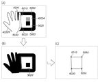
図5及び図6は、部分隠蔽による誤検出の例を説明する図である。図5において、マーカ(矩形マーカ4000A)は、その内部に矩形5020を有している。このようなマーカを利用する場合、矩形5020の4頂点(5030、5040、5050及び5060)を正しく検出する必要がある。
5 and 6 are diagrams for explaining an example of erroneous detection by partial concealment. In FIG. 5, the marker (
しかし、図5(A)に示すように、矩形5020の4頂点のうちの2頂点5030、5040が、ユーザの手4020Rによって隠蔽されている状況においては、図5(B)のような画像処理(例えば二値化)によって矩形5020を検出した場合、手4020Rと矩形5020との接点6010、6020を頂点5030、5040であると誤認識してしまう(図5(C))。
However, as shown in FIG. 5A, in a situation where two
また、図6は、図6(A)に示すマーカ(色領域マーカ4010)の一部が図6(B)に示すようにユーザの手4020Rによって隠蔽された場合を示している。この場合、マーカの重心点として、本来の位置7000ではなく、誤った位置7010が検出されてしまう。
FIG. 6 shows a case where a part of the marker (color region marker 4010) shown in FIG. 6A is hidden by the user's
マーカを利用した撮像装置の位置姿勢算出は、世界座標系において既知なマーカ(又はマーカが有するパターン)の頂点や重心位置が、撮像装置の座標系においてどのような座標として検出されるかを元に行われる。従って、画像中で検出したマーカの特徴点(頂点や重心など)が誤って検出されると、最終的に得られる位置姿勢情報の精度悪化を引き起こす。 The position / orientation calculation of the imaging device using the marker is based on the coordinates at which the vertex or barycentric position of the marker (or the pattern possessed by the marker) known in the world coordinate system is detected in the coordinate system of the imaging device. To be done. Therefore, if the feature points (vertices, centroids, etc.) of the markers detected in the image are erroneously detected, the accuracy of the finally obtained position / orientation information is deteriorated.
しかしながら、従来のマーカ検出方法では、部分隠蔽による誤検出が生じても、誤検出だと判断できないという課題があった。 However, the conventional marker detection method has a problem that even if erroneous detection due to partial concealment occurs, it cannot be determined as erroneous detection.
本発明は、このような従来技術の課題に鑑みなされたものであり、マーカの部分隠蔽が原因で誤検出されたマーカの特徴点(上の例における頂点座標や重心位置)の利用を抑制することをその主な目的とする。 The present invention has been made in view of such a problem of the prior art, and suppresses the use of marker feature points (vertex coordinates and barycentric positions in the above example) that are erroneously detected due to partial concealment of the markers. That is its main purpose.
上述の目的は、撮像されたマーカを撮像画像から検出するマーカ検出方法であって、撮像画像を取得する画像取得工程と、撮像画像から、マーカの形状、色、もしくは模様に対応するマーカ領域を検出するマーカ領域検出工程と、検出されたマーカ領域に、所定色の画素を含んだ隣接領域が存在するか否かを検査する隣接領域検査工程と、検出されたマーカ領域のうち、所定色の画素を含んだ隣接領域が存在するマーカ領域を無効なマーカ領域と判定する判定工程とを有することを特徴とするマーカ検出方法によって達成される。 The above-described object is a marker detection method for detecting a captured marker from a captured image, and an image acquisition process for acquiring the captured image, and a marker region corresponding to the shape, color, or pattern of the marker from the captured image. A marker area detecting step to detect , an adjacent area inspecting step for inspecting whether or not an adjacent area including a pixel of a predetermined color exists in the detected marker area, and a predetermined color of the detected marker areas It is achieved by the marker detection method characterized by comprising a determination step of determining the marker region adjacent region including the pixel exists as invalid marker area.
また、上述の目的は、撮像されたマーカを撮像画像から検出するマーカ検出方法であって、撮像画像を取得する画像取得工程と、撮像画像から、マーカの形状、色、もしくは模様に対応するマーカ領域を検出するマーカ領域検出工程と、検出されたマーカ領域の頂点毎に定められる隣接領域に、所定色の画素を含んだ隣接領域が存在するか否かを検査する隣接領域検査工程と、検出されたマーカ領域の頂点のうち、所定色の画素を含んだ隣接領域が存在する頂点を無効な頂点と判定する判定工程とを有することを特徴とするマーカ検出方法によっても達成される。 The above-described object is a marker detection method for detecting a captured marker from a captured image, an image acquisition step for acquiring the captured image, and a marker corresponding to the shape, color, or pattern of the marker from the captured image. Marker region detection step for detecting a region , adjacent region inspection step for inspecting whether or not an adjacent region including a pixel of a predetermined color exists in the adjacent region determined for each vertex of the detected marker region, and detection among the vertices of the marker region which is also it is realized by the marker detection method characterized in that it comprises a determination step of determining an invalid vertex vertices adjacent region including the predetermined color pixel exists.
本発明によれば、部分隠蔽の可能性のあるマーカをマーカ領域の隣接領域に含まれる色によって判定することで、誤検出されたマーカの特徴点の利用を抑制することが可能になる。従って、撮像部の位置姿勢推定にマーカを用いる場合の推定精度を向上することが可能になる。 According to the present invention, by using a color included in an adjacent area of a marker area to determine a marker that may be partially concealed, it is possible to suppress the use of a misdetected marker feature point. Therefore, it is possible to improve the estimation accuracy when the marker is used for estimating the position and orientation of the imaging unit.
[第1の実施形態]
以下、添付図面を参照して、本発明をその最適な実施形態に基づき詳細に説明する。
以下の説明においては、ビデオシースルー(Video See-Through)型のヘッドマウントディスプレイ(HMD)を用いた複合現実(Mixed Reality : MR)空間提示システムに、本発明の実施形態に係るマーカ検出装置を適用した場合について説明する。
[First embodiment]
Hereinafter, the present invention will be described in detail with reference to the accompanying drawings based on the most preferred embodiments.
In the following description, the marker detection device according to the embodiment of the present invention is applied to a mixed reality (MR) space presentation system using a video see-through type head mounted display (HMD). The case will be described.
本発明のマーカ検出装置により、ビデオシースルー型のHMDに取り付けた撮像部(以降、特に断らない限り「撮像部」という言葉は左右一対のカメラをまとめて指す)の位置姿勢を精度良く推定することができる。その結果、現実空間を撮像した現実空間画像上にコンピュータグラフィックス等により描画された仮想空間の画像をより正しく位置合わせして重畳合成することが可能になり、この合成画像をHMDを通じて観察するユーザが複合現実空間(以下、MR空間と呼称する)を違和感無く、より自然に体験できる。 With the marker detection device of the present invention, accurately estimate the position and orientation of an image pickup unit attached to a video see-through type HMD (hereinafter, unless otherwise specified, the term “image pickup unit” refers to a pair of left and right cameras collectively) Can do. As a result, the virtual space image drawn by computer graphics or the like can be more accurately aligned and superimposed on the real space image obtained by imaging the real space, and the user who observes this composite image through the HMD. However, the mixed reality space (hereinafter referred to as MR space) can be experienced more naturally without a sense of incongruity.
複合現実空間提示システムでは、現実空間の画像と非現実空間(仮想空間)の画像を合成した複合現実空間画像を、HMDを通じて提示することにより、HMDを装着するユーザに複合現実空間(又は複合現実感)を体感させることができる。なお、このような、複合現実感に関する技術(MR技術)についての情報は、例えば、非特許文献1から得ることができる。 In the mixed reality space presentation system, a mixed reality space image (or mixed reality) is presented to a user wearing an HMD by presenting a mixed reality space image obtained by synthesizing an image of a real space and an image of a non-real space (virtual space) through the HMD. Feel). Information about such mixed reality technology (MR technology) can be obtained from Non-Patent Document 1, for example.
MR空間を表現するためには、現実空間中に定義した基準座標系(現実空間に重畳しようとする仮想物体の位置姿勢を決定する基準となる現実空間中の座標系)と、撮像部の座標系(カメラ座標系)との間の、相対的な位置姿勢関係を得ることが不可欠である。なぜなら、仮想物体(仮想空間画像)を違和感なく現実空間画像に重畳表示するためには、現実空間画像を撮影する撮像部の実際のカメラパラメータ(すなわち、焦点距離や主点などのカメラ内部パラメータと撮像部の位置と姿勢を表すカメラ外部パラメータ)と同一のカメラパラメータを用いて仮想物体の画像を生成しなければならないからである。カメラ内部パラメータは撮像部固有で変化しない値であるため、予め用意しておくことが可能である。例えば、現実物体であるテーブル上のある位置に仮想物体を重畳表示する場合には、テーブルに基準座標系を定義し、その基準座標系における撮像部の位置姿勢(カメラ外部パラメータ)を求めればよい。また、観察者が手に保持する現実の箱に何らかの仮想の模様やラベルを重畳表示する場合には、箱自身の物体座標系を基準座標系と考え、カメラ座標系における箱(基準座標系)の位置姿勢を求めればよい。 In order to express the MR space, a reference coordinate system defined in the real space (a coordinate system in the real space serving as a reference for determining the position and orientation of the virtual object to be superimposed on the real space) and the coordinates of the imaging unit It is essential to obtain a relative position and orientation relationship with the system (camera coordinate system). This is because in order to superimpose and display a virtual object (virtual space image) on the real space image, the actual camera parameters of the imaging unit that captures the real space image (that is, the camera internal parameters such as the focal length and principal point) This is because the image of the virtual object must be generated using the same camera parameter as the camera external parameter that represents the position and orientation of the imaging unit. Since the camera internal parameter is a value that is unique to the imaging unit and does not change, it can be prepared in advance. For example, when a virtual object is superimposed and displayed at a certain position on a table that is a real object, a reference coordinate system is defined in the table, and the position and orientation (camera external parameters) of the imaging unit in the reference coordinate system may be obtained. . When a virtual pattern or label is superimposed on an actual box held by an observer, the object coordinate system of the box itself is regarded as a reference coordinate system, and the box in the camera coordinate system (reference coordinate system) What is necessary is just to obtain | require position and orientation.
なお、以下では、基準座標系に対する撮像部(カメラ座標系)の相対的な位置姿勢を、便宜的に「撮像部の位置姿勢」と呼称する。基準座標系と撮像部との間の相対的な位置姿勢とは、基準座標系に対する撮像部の位置姿勢、撮像部に対する基準座標系の位置姿勢、あるいは、これらを表現可能なデータ形式(例えば、基準座標系からカメラ座標系への座標変換行列や、カメラ座標系から基準座標系への座標変換行列)といった、一意に変換可能でありかつ本質的に同一の事象を表す情報を総称するものである。 Hereinafter, the relative position and orientation of the imaging unit (camera coordinate system) with respect to the reference coordinate system will be referred to as “position and orientation of the imaging unit” for convenience. The relative position and orientation between the reference coordinate system and the imaging unit are the position and orientation of the imaging unit with respect to the reference coordinate system, the position and orientation of the reference coordinate system with respect to the imaging unit, or a data format that can express these (for example, This is a collective term for information that can be converted uniquely and represents essentially the same event, such as a coordinate conversion matrix from the reference coordinate system to the camera coordinate system, or a coordinate conversion matrix from the camera coordinate system to the reference coordinate system). is there.
本実施形態では、現実物体の上に配置したマーカを撮影画像中から検出し、そのマーカの検出結果を用いて、物体座標系を基準座標系とした撮像部の位置姿勢を推定する。本実施形態に係るマーカ検出装置によれば、前述の部分隠蔽による誤検出が生じる状況においても、それが誤検出であることを判別することが可能であり、誤検出された情報を利用しないことにより、撮像部の位置姿勢を精度良く求めることが可能である。 In the present embodiment, a marker placed on a real object is detected from a captured image, and the position and orientation of the imaging unit with the object coordinate system as a reference coordinate system are estimated using the detection result of the marker. According to the marker detection apparatus according to the present embodiment, it is possible to determine that it is a false detection even in a situation where a false detection due to the above-described partial concealment occurs, and do not use erroneously detected information. Thus, the position and orientation of the imaging unit can be obtained with high accuracy.
<構成>
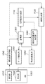
図1は本実施形態に係るマーカ検出装置を含む複合現実空間提示システムの機能構成例を示すブロック図である。また図2は、この複合現実空間提示システムの外観を模式的に示す図である。また図3は、この複合現実空間提示システムの使用時の状態を示す模式図である。尚、各図で同じ部分については同じ番号を付けている。
<Configuration>
FIG. 1 is a block diagram illustrating a functional configuration example of a mixed reality space presentation system including a marker detection device according to the present embodiment. FIG. 2 is a diagram schematically showing the appearance of this mixed reality space presentation system. FIG. 3 is a schematic diagram showing a state in use of the mixed reality space presentation system. In each figure, the same number is assigned to the same part.
本実施形態において、複合現実空間提示システムは、観察者(ユーザ)4030が位置姿勢を変更可能な可動物体3010を用い、可動物体3010の位置姿勢に応じて可動物体3010の近辺に仮想物体を表示するものとする。
In the present embodiment, the mixed reality space presentation system uses a
HMD1000には、撮像部1010、表示部1030が設けられている。本実施形態では図2に示すように、撮像部1010と表示部1030とは2つずつあり、撮像部1010R、表示部1030Rは右目用、撮像部1010L、表示部1030Lは左目用である。このような構成を有することにより、このHMD1000を頭部に装着した観察者4030の右目と左目には、視差画像を提示することができ、複合現実空間を三次元表示することが可能である。
The
つまり、本実施形態では、撮像部1010Rが撮像した現実空間の画像と、後段のワークステーション2040が生成した右目用の仮想空間の画像とが重畳された右目用の複合現実空間画像(この重畳画像を以下、MR画像と呼称する)を表示部1030Rにより右目に提示し、撮像部1010Lが撮像した現実空間の画像と、後段のワークステーション2040が生成した左目用の仮想空間の画像とが重畳された左目用のMR画像を表示部1030Lにより左目に提示するので、結果として観察者4030はステレオMR画像を観察することができる。なお、このようなステレオMR画像の生成、提示に関する一般的な手法自体は周知であり、かつ本発明の本質とは関係ないため、これ以上の説明は行わない。
That is, in the present embodiment, a mixed reality space image for the right eye (this superimposed image) in which the image of the real space captured by the
また、本実施形態に係るマーカ検出装置は、一つの撮像部、表示部を右目、左目で共有するシステム(即ち観察者4030がモノラルMR画像を観察する場合)や、MR画像を単眼のみに表示するシステムに対しても適用可能である。
In addition, the marker detection apparatus according to the present embodiment is a system in which one imaging unit and display unit are shared by the right eye and the left eye (that is, when the
また、現実空間画像を取得し、また観察者4030にMR画像を提示するための手段として本実施形態ではHMDを用いるが、撮像部1010と表示部1030を少なくとも1対有する装置であれば任意の装置が利用可能である。さらには、撮像部1010と表示部1030とは互いに固定されている必要もない。
Further, in this embodiment, an HMD is used as a means for acquiring a real space image and presenting an MR image to the
なお、説明を簡潔にし、また理解を容易にするために、以下、特に右目用、左目用等の、ステレオ画像を表す修飾語により特定される場合を除き、撮像部、表示部はそれぞれ1つの構成要素として取り扱う。また、システム内の他の構成要素や、そこで行われる処理や生成される画像についても、1つの要素、処理、画像として取り扱う。
撮像画像取得部1040は、撮像部1010によって撮像された現実空間の撮像画像(カラー画像)を入力し、画像データとして後述する記憶部1090に出力する。
For the sake of brevity and ease of understanding, the imaging unit and the display unit are each provided with one imaging unit and one display unit, respectively, except for the case specified by the modifiers representing stereo images, particularly for the right eye and the left eye. Treat as a component. In addition, other components in the system, processes performed there, and generated images are also handled as one element, process, and image.
The captured
マーカ検出部1050では、記憶部1090が保持している撮像画像の中からマーカの検出を行う。本実施形態では、マーカとして、図4に示すような、矩形形状のマーカ(以降、矩形マーカと呼ぶ)を用いる。矩形マーカ4000は、図4(A)に示すように、内部に白い矩形パターン5020を有し、矩形パターン5020の内部に、マーカの向きを表すための小型の黒い矩形パターン5010と、IDを表すための色付きの小型矩形パターン5000(IDパターン)が隣接して配置されるマーカである。また、白色矩形パターン5020の周囲には、白色矩形パターン5020の検出を容易にするために白と区別しやすい色を有する枠が設けられている。なお、本実施形態において、検出すべき領域は白色矩形パターン5020であり、白色矩形パターン5020の検出ができれば枠部分は不要である。つまり、マーカとして機能するのは白色矩形パターン5020である。そのため、以下の説明では白色矩形パターン5020のことをマーカとして説明する。もちろん、図6に示したマーカのような枠の無いマーカを用いることも可能である。マーカ検出部1050の動作については後で詳細に説明する。
The
本実施形態においては、図3に示すように、可動物体3010には判別可能な異なる色のIDパターン5000を有する2つの矩形マーカ4000A,4000Bが設置されている。これらのマーカの配置情報(物体座標系4050における各頂点の3次元座標や各マーカのIDパターンの色情報など)は、予め記憶部1090に記憶されている。
In the present embodiment, as shown in FIG. 3, two
隣接色検査部1060は、マーカ検出部1050が生成し、記憶部1090に記憶されている検出マーカのリストに含まれる各マーカに対して、部分隠蔽(誤検出)の可能性があるかどうかを判定し、部分隠蔽(誤検出)の疑いのあるマーカを検出マーカリストから削除する。隣接色検査部1060の動作については後で詳細に説明する。
The adjacent
記憶部1090では、本実施形態における複合現実空間提示システムの処理に必要な情報を保持し、処理に応じて情報の読み出しや更新を行う。複合現実空間提示システムの処理に必要な情報とは、例えば、マーカの配置情報、描画する仮想物体の頂点情報、仮想物体の配置情報といった、予め用意される情報に加え、撮像画像や、後述する二値化画像、検出マーカのリスト(IDと各頂点の画像座標)など、処理中に発生する情報が含まれる。
The
仮想画像生成部1110は、撮像部位置姿勢推定部1080が出力する撮像部1010の位置姿勢と、記憶部1090に保存される情報に基づいて、撮像部の位置姿勢から見える仮想物体の画像を生成(描画)する。
The virtual
画像合成部1120は、記憶部1090が保持している撮像画像と、仮想画像生成部1110から得られる仮想物体の画像(仮想空間の画像)とを合成した画像(MR画像)を生成する。この合成については、撮像画像の上に仮想画像生成部1110からの仮想画像を重畳することにより行われる。
The
この重畳処理時に、撮像画像から仮想物体より手前に表示すべき領域(例えば図3の例では観察者の手の領域)を検出し、この領域に対しては仮想空間の画像を上書き描画しない(撮像画像をそのまま描画する)ことにより、物体3010を持つ手の上に仮想物体が描画されるという不自然さが生じないようにしてもよい。
During this superimposition process, a region to be displayed in front of the virtual object is detected from the captured image (for example, the region of the observer's hand in the example of FIG. 3), and the virtual space image is not overwritten on this region ( By drawing the captured image as it is, it may be possible to prevent unnaturalness that the virtual object is drawn on the hand holding the
そして、画像合成部1120は、生成したMR画像をHMD1000の表示部1030に出力する。これにより、表示部1030には、撮像部1010の位置姿勢に応じた現実空間の画像と仮想空間の画像とが重畳されたMR画像が表示され、このHMD1000を頭部に装着したユーザに、複合現実空間を体験させることができる。
Then, the
なお、図1において、HMD1000を除くすべての機能は、ワークステーション3040の機能構成に含まれるものとする。
ワークステーション3040の基本構成はパーソナルコンピュータとして市販されているコンピュータと同様であり、CPU、RAM、ROM、外部記憶装置(ハードディスクドライブなど)、記憶媒体ドライブ装置(CD、DVDなどリムーバブル記憶媒体にアクセスするためのドライブ)、ビデオキャプチャボード、グラフィックボード、表示装置(LCD、CRTモニタなど)及び入力デバイス(キーボード、マウス、タブレット、ジョイスティックなど)を備える。
In FIG. 1, all functions except for the
The basic configuration of the
そして、CPUは、ワークステーション3040全体の制御を行うと共に、上記MR画像を生成し、HMD1000の表示部1030に出力するまでの一連の処理を実行する。また、RAMは、外部記憶装置や記憶媒体ドライブ装置からロードされたプログラムやデータを一時的に記憶するためのエリアを備えると共に、CPUが各種の処理を実行するために用いるワークエリアも備える。
The CPU controls the
ROMは、ブートプログラムなど、本装置全体の制御を行うためのプログラムやデータ等を格納する。
入力デバイスは、ユーザ(観察者ではなく、ワークステーション3040のオペレータ)が、複合現実空間提示システムを実現するアプリケーションに対し、表示装置に示されるGUIを通じて各種設定を行ったり、各種の指示を入力するために用いられる。
The ROM stores programs, data, and the like for controlling the entire apparatus such as a boot program.
The input device allows the user (not the observer but the operator of the workstation 3040) to make various settings or input various instructions to the application that realizes the mixed reality space presentation system through the GUI displayed on the display device. Used for.
ハードディスクドライブ装置等に代表される外部記憶装置は、本実施形態の複合現実空間提示システムを実現するためのアプリケーションソフトウエアはもとより、処理に必要なデータや、アプリケーションソフトウエアが動作するOS(オペレーティングシステム)、を格納する。 An external storage device typified by a hard disk drive or the like is not only application software for realizing the mixed reality space presentation system of this embodiment, but also data necessary for processing and an OS (operating system on which application software operates). ).
このような構成を有する複合現実空間提示システムにおいて、例えば、記憶部1090は外部記憶装置、記憶媒体ドライブ装置、RAMにより、また撮像画像取得部はビデオキャプチャボード、画像合成部1120はグラフィックボードにより実現され、他のマーカ検出部1050、隣接色検査部1060、撮像部位置姿勢推定部1080及び仮想画像生成部1110はRAMやROMに格納されているプログラムやデータを用いて、CPUにより実現することができる。
In the mixed reality space presentation system having such a configuration, for example, the
<処理の手順>
次に、本実施形態における複合現実空間提示システムの全体的な処理の流れを図8のフローチャートを参照して説明する。上述のように、この処理はワークステーション3040が有するCPUが記憶部1090に格納されるプログラムを実行して図1の各部を制御することによって実現される。なお、図8で示される処理は、MR画像を1枚生成するごとに繰り返し行われる処理である。
<Processing procedure>
Next, the overall processing flow of the mixed reality space presentation system in the present embodiment will be described with reference to the flowchart of FIG. As described above, this processing is realized by the CPU of the
ステップS9010において、撮像画像取得部1040は撮像部1010にて撮像される撮像画像を取得して、記憶部1090に書き込む。
ステップS9030において、マーカ検出部1050は、記憶部1090から撮像画像を読み出し、マーカ検出処理を実行して、検出されたマーカのリストを記憶部1090に保存する。マーカ検出処理の詳細は後述する。
In step S9010, the captured
In step S9030, the
ステップS9050において、隣接色検査部1060は、記憶部1090に保持されている検出マーカのリスト中の全マーカに関して、部分隠蔽(誤検出)の疑いのあるマーカを判定し、部分隠蔽(誤検出)の疑いありと判断されたマーカのデータをリストから削除する。この処理についても詳細は後述する。
In step S9050, the adjacent
ステップS9100において、撮像部位置姿勢推定部1080は、マーカリスト中の複数のマーカの画像座標と、予め記憶部1090に登録されている、夫々のマーカの基準座標系における3次元座標とから、撮像部1010の位置姿勢を推定し、仮想画像生成部1110に出力する。基準座標系における複数の点の3次元座標(マーカの頂点座標など)とそれらの投影像の画像座標(撮像画像から検出されたマーカの頂点座標など)から、投影像を撮像した撮像部の位置姿勢を求める方法は本発明と直接関係せず、また公知な技術であるので、詳細な説明は省略する。例えば、前フレームでの位置姿勢を初期値として、画面上における対応点の誤差が最小になるように撮像部の位置姿勢を繰り返し修正する方法(非特許文献3参照)や、同一平面内の点のみを用いてホモグラフィ演算を用いて撮像部の位置姿勢を求める手法(非特許文献1参照)等を用いることが可能である。
In step S9100, the imaging unit position /
本実施形態においては、撮像部位置姿勢推定部1080による撮像部の位置姿勢推定処理時に、部分隠蔽の疑いのあるマーカの情報を用いないため、従来よりも精度良く撮像部の位置姿勢を求めることができる。
In the present embodiment, since the information of the marker that is suspected of partial concealment is not used during the position and orientation estimation process of the image capturing unit by the image capturing unit position and
ステップS9110においては、仮想画像生成部1110が予め用意された仮想空間モデル(仮想物体の形状など、仮想空間を描画するために必要な情報)と、撮像部位置姿勢推定部1080から得た撮像部の位置姿勢に基づいて仮想物体の画像を描画し、画像合成部1120へ出力する。そして、画像合成部1120は、この仮想画像を記憶部1090から読み出した撮像画像(現実空間画像)上に重畳合成してMR画像を生成し、表示部1030に出力する。
In step S9110, a virtual space model (information necessary for drawing a virtual space such as the shape of a virtual object) prepared in advance by the virtual
<マーカ検出処理>
次に、ステップS9030でマーカ検出部1050が行うマーカ検出処理について、図10のフローチャートを用いて説明する。
マーカ検出部1050は、まず始めに、記憶部1090から撮像画像を読み出す(ステップS101)。図4(A)は、撮像された矩形マーカの像の一例を表す。次に図4(B)で示すように、画像の各画素の明度に基づいた閾値処理によって、白黒の二値化画像を生成し、記憶部1090に保存する(ステップS105)。
<Marker detection processing>
Next, the marker detection process performed by the
First, the
そして、生成した二値化画像の中で白い領域に対してラベリングを行い、ラベリングされた領域(ラベル領域)毎に、その外周を表す画素の並びを抽出する。次に、各ラベル領域の中で、得られた画素の並びが、一定値以上の長さを持つ4つの線分から構成されるラベル領域を矩形マーカ候補として選定(図4(B)の5020’)し、4つの折れ点を探す。次いで図4(C)で示すように、各2頂点間に直線当てはめ処理を施すことで線分を求め、この4つの線分の交点を矩形マーカ候補の4頂点とする(ステップS107)。抽出されたマーカ候補は例えば記憶部1090にマーカ候補リストを生成し、頂点座標とともに登録する(ステップS109)。
Then, labeling is performed on a white region in the generated binarized image, and an array of pixels representing the outer periphery is extracted for each labeled region (label region). Next, in each label area, a label area composed of four line segments having a length equal to or greater than a certain value is selected as a rectangular marker candidate (5020 ′ in FIG. 4B). ) And search for four break points. Next, as shown in FIG. 4C, a line segment is obtained by applying a straight line fitting process between the two vertices, and the intersection of the four line segments is set as the four vertices of the rectangular marker candidate (step S107). For the extracted marker candidates, for example, a marker candidate list is generated in the
次に、検出された各マーカ候補が実際のマーカの投影像であるか、ノイズや意図しない物体の映り込みによるマーカ以外のものの誤検出であるかの検証を行うと同時に、画像面上でのマーカの向きを判定する(ステップS111)。図7は検証の処理を示す概念図である。検証は、矩形マーカ候補の対角線を2本引き、各対角線を3等分する点8010、8020、8030、8040(2本の対角線で合計4点)における二値化画像(マーカ検出処理過程で生成された図4(B)の画像)上の画素値を用いて行う。具体的には、各点を起点として4点を反時計回りに(例えば、8030を起点とした8030、8020、8040、8010の4点)見たときに、画素値が[黒,任意,白,白]という並びになるような配置があるか否かを検証し、そのような配置がある場合は、そのマーカ候補を矩形マーカであると判定する(ステップS113、”N”)。それ以外の場合(ステップS113、”Y”)は、そのマーカ候補は誤検出されたものと判定し、マーカ候補のリストから削除する(ステップS115)。図7の例では、8040を起点とした際にこの条件を満たし、矩形マーカであると判定される。
Next, it is verified whether each detected marker candidate is a projected image of an actual marker or a false detection of something other than a marker due to reflection of noise or an unintended object, and at the same time, The direction of the marker is determined (step S111). FIG. 7 is a conceptual diagram showing verification processing. The verification is performed by drawing two diagonal lines of the rectangular marker candidate, and binarized images (generated during the marker detection process) at
また、マーカ検出処理過程で生成した二値化画像を用いずに、撮像画像の画素値(明度)を参照することにより、予め定めた基準により[暗,任意,明,明]という並びとなるかどうかにより判定してもよい。この処理は、誤検出を判定すると同時にマーカの向きを得る処理も含んでおり、マーカであると判定された矩形マーカは、画面上における向きが一意に特定できる。すなわち、起点(図7の例では8040)に一番近い頂点が5050(矩形5010に一番近い頂点)となり、以下反時計回りに、5060、5030、5040の順で頂点にIDを割振ることができる。 Further, by referring to the pixel value (brightness) of the captured image without using the binarized image generated in the marker detection process, the arrangement is [dark, arbitrary, bright, bright] based on a predetermined criterion. It may be determined depending on whether or not. This process includes a process of determining the false detection and obtaining the direction of the marker, and the rectangular marker determined to be the marker can uniquely identify the direction on the screen. That is, the vertex closest to the starting point (8040 in the example of FIG. 7) becomes 5050 (vertex closest to the rectangle 5010), and IDs are assigned to the vertexes in the order of 5060, 5030, and 5040 in the following counterclockwise direction. Can do.
最後に、検出された矩形マーカが、可動物体3010に設置された複数のマーカのうちのどのマーカであるかを同定する(ステップS117)。矩形マーカのIDはマーカ内部の色付きの小型矩形5000によって表されているので、検出された矩形マーカの投影像から、小型矩形5000上の点(マーカの向きの検出処理で利用した対角線上の4点のうちの、起点の右隣の点(図7の例では8010)がこれに相当する)の色によって判別する。ただし、この色付きの小型矩形5000の色は、マーカ検出処理過程で生成された二値化画像から取得するのではなく、検出処理に利用した撮像画像(カラー画像)の同じ画素位置を参照し、色を取得するものとする。
Finally, it is identified which of the plurality of markers installed on the
マーカ検出部1050により得られた以下の処理結果は、記憶部1090に格納される。
・検出マーカのリスト(IDと各頂点の画像座標)
・マーカ検出処理過程で生成された二値化画像
検出マーカのリストの例を図12に示す。図12において、No.は検出マーカの連番である。そして、各頂点の座標が順次格納され、最後に同定されたマーカのIDが格納される。
The following processing results obtained by the
・ List of detection markers (ID and image coordinates of each vertex)
An example of a list of binarized image detection markers generated in the marker detection process is shown in FIG. In FIG. 12, No. is a sequential number of the detection marker. Then, the coordinates of each vertex are sequentially stored, and the ID of the marker identified last is stored.
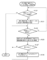
<部分隠蔽の疑われるマーカの検出・削除処理>
次に、ステップS9050で隣接色検査部1060が行う処理について、図11のフローチャートを用いて説明する。
隣接色検査部1060は、記憶部1090に記憶されている検出マーカのリストに含まれる各マーカに対して、その隣接する領域に指定された色が含まれているかどうかを検査し、隣接領域に指定色が含まれているマーカを検出リストから削除する。
<Detection / deletion processing of markers suspected of partial concealment>
Next, the processing performed by the adjacent
The adjacent
予め指定する色に特に制限はなく、マーカを利用するアプリケーションの内容などに応じてマーカを隠蔽する可能性のある物体の色などを指定すればよい。本実施形態における隣接色検査部1060においては、図3に示したように、観察者が手でマーカを隠蔽する可能性があるアプリケーションを想定する。この場合、図5(A)における矩形マーカ4000Aのように、観察者の手によってマーカの一部が隠蔽されている状況では、図5(C)に示す、マーカとして検出された矩形領域(以下、マーカ領域と称する)に隣接する領域にユーザの手の画像が存在する。したがって、手による隠蔽の可能性を判定するには、ユーザの肌の色を指定色として記憶部1090に登録しておき、マーカ領域の隣接領域に指定色の画素が存在するか否かを検出することにより、手による隠蔽が生じている可能性の有無を検出することができる。
The color designated in advance is not particularly limited, and the color of an object that may hide the marker may be designated according to the contents of the application that uses the marker. In the adjacent
なお、上述したように、奥行き関係を正確に表したMR画像を生成するため、仮想物体より手前にあるように(仮想物体に隠されないように)描画すべき領域の抽出を行う場合であって、ユーザの手の領域など肌色領域を抽出する場合には、隣接色検査部1060で検出した肌色の領域に関する情報を仮想画像生成部1110で利用して仮想物体の画像を描画することで、処理の効率化を計ることも可能である。ただし、この場合には、肌色を検出すべき隣接領域の範囲をより大きくする必要がある。
Note that, as described above, in order to generate an MR image that accurately represents the depth relationship, the region to be drawn is extracted so as to be in front of the virtual object (so as not to be hidden by the virtual object). When extracting a skin color area such as a user's hand area, the virtual
あるいは、指定色(ここでは肌色)領域の抽出を行う肌色領域抽出部を別途設け、記憶部1090から読み出した撮影画像中に含まれる肌色領域を抽出し、その領域に関する情報を仮想画像生成部1110での仮想画像生成処理及び隣接色検査部1060での処理に利用するようにしてもよい。この場合、肌色領域抽出部が例えば記憶部1090に肌色領域の撮像画像中の座標値を記憶し、その座標値を参照して仮想画像生成及び隣接領域における肌色画素の有無を調べることができ、効率的な処理が可能になる。このような肌色領域抽出部も、隣接色検査部1060と同様、CPUによってソフトウェア的に実現することが可能である。
Alternatively, a skin color region extraction unit that extracts a specified color (here, skin color) region is separately provided, a skin color region included in the captured image read from the
マーカ領域の「隣接領域」は、記憶部1090に保持されている二値化画像(マーカ検出部1050におけるマーカ検出処理過程(図10のステップS105)で生成された画像)に含まれているマーカ領域に膨張処理を施し、得られた領域(マーカ領域よりも全体的に大きな領域)から元のマーカ領域を取り除いた領域として得ることができる。なお、2次元画像処理における領域の膨張処理は公知の技術であるため、ここでの説明は省略する。また、検査の対象となる「隣接領域」の範囲はマーカ領域の周辺1画素であってもよいし、より大きな幅を持つ領域を隣接領域として検査しても良い。 The “adjacent area” of the marker area is a marker included in the binarized image held in the storage unit 1090 (the image generated in the marker detection process in the marker detection unit 1050 (step S105 in FIG. 10)). It can be obtained as an area obtained by performing expansion processing on the area and removing the original marker area from the obtained area (area larger than the marker area as a whole). In addition, since the expansion process of the area | region in a two-dimensional image process is a well-known technique, description here is abbreviate | omitted. Further, the range of the “adjacent area” to be inspected may be one pixel around the marker area, or an area having a larger width may be inspected as an adjacent area.
隣接領域における肌色画素の有無の判定は、二値化画像上で隣接領域とされた領域に対して撮像画像上の対応する座標の各画素を検査することで行う。本実施形態では、肌色を示すYCbCr値(Y,Cb,Crのそれぞれの上限値と下限値)を記憶部1090に登録しておき、隣接領域における肌色画素の(正確には、肌色を示すYCbCr値の範囲に含まれる画素値を有する画素の)有無を検出する。なお、隠蔽を起こす可能性がある物体の色として、肌色のみではなく、撮像する空間に存在する他の物体の色を指定することも可能であるし、複数色を同時に指定してもよい。
The determination of the presence or absence of skin color pixels in the adjacent area is performed by inspecting each pixel of the corresponding coordinates on the captured image with respect to the area that is the adjacent area on the binarized image. In the present embodiment, YCbCr values indicating the skin color (upper and lower limits of Y, Cb, and Cr) are registered in the
図11において、隣接検査部1060はまず記憶部1090の検出マーカリストに登録された検出マーカの全てに対して処理を行ったかどうかを調べる(ステップS121)。全ての検出マーカに対して処理を行った場合には処理を終了し、未処理の検出マーカがあればステップS123へ移行する。
In FIG. 11, the
ステップS123では、記憶部1090に記憶された二値化撮像画像から、処理対象の検出マーカの隣接領域を抽出する。そして、ステップS125で、抽出した隣接領域に対応する(二値化されていない、カラーの)撮像画像の領域中に、指定色の画素が含まれるかどうか調べる。その結果、指定色画素が含まれていれば、処理対象の検出マーカ(に関する情報)を検出マーカのリストから削除する(ステップS129)。一方、指定色画素が含まれていなければ、ステップS121へ戻って未処理の検出マーカが残っているか調べる。
In step S123, the adjacent area of the detection marker to be processed is extracted from the binarized captured image stored in the
なお、ステップS125の処理において、隣接領域に指定色画素が含まれると判断する基準は、部分隠蔽の原因となりうる物体の種類や大きさなどの条件や、実際の試行錯誤になどに基づいて適宜定めることが可能である。例えば、隣接領域に1画素でも指定色画素が含まれれば「含まれる」と判定するようにしてもよいし、所定数(又は割合)以上含まれる場合や所定数以上連続して(又はある画素数以上の領域が)含まれる場合に「含まれる」と判定するようにしてもよい。また、複数の条件を組み合わせて判定しても良い。さらに、指定色が複数存在する場合には、指定色毎に判定条件を定めることもできる。 In the process of step S125, the criterion for determining that the designated color pixel is included in the adjacent region is appropriately determined based on conditions such as the type and size of an object that may cause partial concealment, actual trial and error, and the like. It is possible to determine. For example, it may be determined as “included” if at least one specified color pixel is included in the adjacent region, or if it is included in a predetermined number (or ratio) or more, or a predetermined number or more (or a certain pixel) It may be determined that “included” if more than a certain number of regions are included. Moreover, you may determine combining several conditions. Furthermore, when there are a plurality of designated colors, a determination condition can be set for each designated color.
以上説明したように、本実施形態によれば、簡便な処理によって部分隠蔽の疑いのあるマーカを判定することが可能であり、このようなマーカを用いずに撮像部の位置姿勢を推定することで、より精度の良い位置姿勢推定結果を得ることが可能になる。 As described above, according to the present embodiment, it is possible to determine a marker that is suspected of partial concealment by simple processing, and to estimate the position and orientation of the imaging unit without using such a marker. Thus, it is possible to obtain a more accurate position and orientation estimation result.
[変形例1]
第1の実施形態においては、検出マーカの隣接領域に特定の色が存在する場合に、そのマーカが部分隠蔽されている疑いがあると判定して、検出マーカのリストから削除していた。しかし、部分隠蔽による誤検出の判定方法は、これに限定されるものではなく、マーカを設置した周辺領域の色(周辺色)をマーカが隠蔽されていないときに取得して記憶部1090に登録しておき、隣接色検査部1060においては、登録されている周辺色以外の色が検出マーカの隣接領域に含まれるか否かを判定し、周辺色以外の色が検出された場合に、そのマーカを検出マーカのリストから削除するという手法を用いてもよい。
[Modification 1]
In the first embodiment, when a specific color exists in the adjacent area of the detection marker, it is determined that the marker is suspected to be partially hidden, and is deleted from the list of detection markers. However, the determination method of erroneous detection by partial concealment is not limited to this, and the color (peripheral color) of the peripheral area where the marker is installed is acquired and registered in the
本変形例における複合現実空間提示システムの構成は、図1のブロック図と同様である。ただし、隣接色検査部1060の内部処理が異なっている。あらかじめ記憶部1090に登録する周辺色としては、マーカの周辺部の色(図4の例では黒)を人手で登録しておいても良いし、マーカの周りを隠蔽されていない状態で撮像することで自動的に収集しても良い。例えば、マーカを中心とする半球上を縦横10分割する間隔で撮像することにより、様々な方向からの周辺色を収集することができる。ただし、収集の過程で注意しなければならないのは、隠蔽を起こす可能性が高い色(本実施形態においては、手の肌色)が周辺色として撮像画像に入らないように、現実空間の物体を肌色でないものに取り替えたり、空間から取り除く必要があるということである。
The configuration of the mixed reality space presentation system in the present modification is the same as the block diagram of FIG. However, the internal processing of the adjacent
本変形例における処理の手順は、図11のステップS125における処理を、指定された色ではなく、予め登録された周辺部の色以外の色の存在を判定する処理とすればよい。その他の処理は図11と同じ流れとなる。 In the processing procedure in this modification, the processing in step S125 of FIG. 11 may be processing for determining the presence of a color other than the peripheral color registered in advance instead of the designated color. The other processes are the same as in FIG.
本変形例の手法により、例えば、手によるマーカの部分隠蔽が起こるような状態であっても、手の色は周辺色として登録されていないため、隠蔽を検出できる。その結果、正しく検出されたマーカのみを利用して撮像部1010の位置姿勢を推定することができ、やはり精度向上が実現される。
According to the method of this modification, for example, even if the marker is partially hidden by the hand, the color of the hand is not registered as a peripheral color, so that the masking can be detected. As a result, it is possible to estimate the position and orientation of the
[変形例2]
第1の実施形態においては、部分隠蔽の疑いがあると判断された矩形マーカが検出マーカとしてリストに含まれていた場合、その矩形マーカをリストから削除していた。つまり、部分隠蔽の疑いがあると判断された検出マーカから得られた全ての情報(すなわち、4つの頂点情報全て)を利用しないものであった。しかし、部分隠蔽された検出マーカであっても、隠蔽されていない頂点5050、5060に関する情報は正しく検出されている。本変形例では、部分隠蔽の疑いがある検出マーカの、隠蔽されていないと考えられる頂点情報については破棄せず、撮像画像推定部1080における位置姿勢の算出に用いることを特徴とする。
[Modification 2]
In the first embodiment, when a rectangular marker determined to be partially concealed is included in the list as a detection marker, the rectangular marker is deleted from the list. That is, all the information (that is, all the four vertex information) obtained from the detection marker determined to be suspected of partial concealment is not used. However, even if the detection marker is partially hidden, information regarding the
本変形例における複合現実空間提示システムの構成は、図1のブロック図と同様である。ただし、隣接色検査部1060の内部処理が異なっている。第1の実施形態では、隣接色検査部1060において、検出マーカの隣接領域を一括して検査していた。これに対し、本変形例では、検出マーカの各頂点の隣接領域に対してそれぞれ独立に検査を行う。すなわち、各頂点を中心とする所定の隣接領域(例えば、半径10画素の円に含まれる隣接領域)の画素に関して検査を行い、1つの頂点の周辺領域に指定された色がある場合は、その頂点をリストから削除する。この場合、頂点の座標値を削除しても良いが、無効化することが出来れば、どのような方法を用いても良い。例えば、図13に示すように、検出マーカのリスト中における当該検出マーカの当該頂点に部分隠蔽による誤検出であることを示すフラグfを設け、通常は0、誤検出された頂点座標については1にすることで、座標値は残すが、無効であることを明示する方法であっても良い。このように利用できる頂点はリストに残しておくことで、撮像部位置姿勢推定部1080において、一部が隠蔽されている矩形マーカに対しても、隠蔽されていない部分の頂点の情報を、撮像部1010の位置姿勢の推定に利用することができる。
The configuration of the mixed reality space presentation system in the present modification is the same as the block diagram of FIG. However, the internal processing of the adjacent
本実施形態における処理の手順を示すフローチャートを図9に示す。図9は、第1の実施形態において説明した図11の処理と基本的な処理は共通である。異なる点は、隣接領域の抽出を頂点毎に行うこと(ステップS131)、隣接領域中の指定色画素の有無検査(ステップS125、S127)を頂点単位で行うこと(そのための判定ステップS133が追加されていること)、及び指定色を含む隣接領域に対応する頂点のみを削除(フラグをセットすることによる無効化、ステップS135)する点である。 FIG. 9 is a flowchart showing a processing procedure in this embodiment. In FIG. 9, the basic processing is common to the processing of FIG. 11 described in the first embodiment. The difference is that the adjacent area is extracted for each vertex (step S131), and the presence / absence check of the designated color pixel in the adjacent area (steps S125 and S127) is performed on a vertex basis (the determination step S133 for that is added). And only the vertices corresponding to the adjacent area including the specified color are deleted (invalidated by setting a flag, step S135).
なお、変形例1と変形例2を組み合わせて用いることはもちろん可能であり、あらかじめ指定した色以外の色が検出された場合に、その頂点を削除(無効化)するという方法を用いてもよい。 Of course, it is possible to use a combination of Modification 1 and Modification 2, and a method of deleting (invalidating) a vertex when a color other than a color designated in advance is detected may be used. .
[変形例3]
第1の実施形態においては、図4に示すような特徴をもつ矩形マーカを用いたが、このマーカ以外のマーカであっても、部分隠蔽による誤検出の判別を行うことができる。例えば、非特許文献1に開示されている内部に同定用パターンを持つ矩形マーカを用いる場合には、マーカ検出部1050を、固定閾値による2値化、テンプレートマッチングによるマーカ識別、輪郭線データの直線あてはめによる頂点位置検出、という当該マーカの検出部に置き換える。このようにして検出されたマーカ領域と検出マーカのリストを記憶部1090に保持させることにより、前述の隣接色検査部1060の処理によって部分隠蔽による誤検出マーカを削除することが可能である。
[Modification 3]
In the first embodiment, the rectangular marker having the characteristics as shown in FIG. 4 is used. However, even with a marker other than this marker, it is possible to determine erroneous detection by partial concealment. For example, when a rectangular marker having an identification pattern is used as disclosed in Non-Patent Document 1, the
また、図6に示したような、背景と区別できる色を備えた円形状のマーカ(以降、色領域マーカと呼ぶ)を用いる場合であっても、同様な部分隠蔽による誤検出の判別を行うことができる。この場合、マーカ検出部1050を特定の形状ではなく、特定の色領域を検出する処理に置き換え、検出された色領域に対して前述の隣接色検査部1060の処理を施すことによって、部分隠蔽による誤検出マーカを削除できる。その他、どのような外観上の特徴を有するマーカを用いる場合であっても、部分隠蔽が生じた場合に隣接領域にそれを隠蔽する物体色(例えば肌色)が存在するという特性が成立する限りにおいては、本実施形態で説明した手法で、部分隠蔽による誤検出マーカを撮像部の位置姿勢推定処理への使用から除外することができる。
In addition, even when a circular marker having a color distinguishable from the background (hereinafter referred to as a color area marker) as shown in FIG. 6 is used, the same erroneous detection by partial concealment is performed. be able to. In this case, the
[変形例4]
また、第1の実施形態においては、マーカ検出部1050と隣接色検査部1060が独立していたが、隣接色検査部1060の処理工程はマーカ検出部1050の機能に含まれていても良い。この場合、隣接色検査の工程は必ずしもマーカ検出処理の後に行う必要は無い。例えば、矩形当てはめによるマーカ候補領域の検出を行った後に、隣接色検査を行って部分隠蔽の可能性のある領域を削除し、その後にノイズ除去や方向検出以降の処理を行っても良いし、他の順序で処理を行っても良い。発明の本質は、これらの処理の順序に依存するものではない。
[Modification 4]
In the first embodiment, the
[変形例5]
第1の実施形態における複合現実空間提示システムは、手に保持して移動させることの可能な現実物体3010上に仮想物体を重畳表示することを目的としていた。しかし、現実空間と撮像部との関係はこれに限定されるものではなく、例えば、室内空間に仮想物体を重畳表示することを目的として、室内空間に貼られたマーカを観測することで室内空間における撮像部の位置姿勢を計測する場合であっても、第1の実施形態と同様な構成によって、部分隠蔽されたマーカの情報を用いることによる位置姿勢推定精度の低下を抑制可能な可能な複合現実空間提示システムを構成することができる。
[Modification 5]
The mixed reality space presentation system according to the first embodiment is intended to superimpose and display a virtual object on a
[変形例6]
なお、第1の実施形態において示した部分隠蔽によるマーカ誤検出の判定方法の適用範囲は、第1の実施形態において示した構成による複合現実感提示システムに限定されるものではない。例えば、非特許文献3に開示されているような、HMD1000に6自由度位置姿勢センサをさらに装着し、室内空間に貼られたマーカを観測することでセンサ計測値の誤差を補正する機構を備える複合現実空間提示システムにおいても、適用することが可能である。このような構成においても、マーカ情報から撮像部の位置姿勢を推定し、その推定結果を用いてセンサ測定値の補正を行うのであるから、マーカから推定される位置姿勢の精度向上は最終的な推定位置姿勢の精度を向上させる。
[Modification 6]
In addition, the application range of the determination method of marker false detection by partial concealment shown in the first embodiment is not limited to the mixed reality presentation system having the configuration shown in the first embodiment. For example, as disclosed in Non-Patent Document 3, the
このように、上述した手法は撮像画像中のマーカ座標と既知のマーカ座標とを利用して撮像部の位置姿勢を求めるいずれの複合現実空間提示システムにおいても適用可能である。さらには、複合現実感提示システムに限らず、マーカを検出することで撮像装置(あるいは撮像装置を装着した物体。あるいは、撮像装置によって観測されている物体)の位置姿勢を求めるあらゆる用途においてマーカ検出の信頼性を向上させる目的で用いることが可能であるし、位置姿勢推定以外の目的であっても、画像上におけるマーカ検出を正確に行う何れの用途においても、適用することが可能である。 As described above, the above-described technique can be applied to any mixed reality space presentation system that obtains the position and orientation of the imaging unit using the marker coordinates in the captured image and the known marker coordinates. Furthermore, not only in the mixed reality presentation system, marker detection is performed in any application that obtains the position and orientation of an imaging device (or an object equipped with the imaging device or an object observed by the imaging device) by detecting a marker. It can be used for the purpose of improving the reliability of the image, and can be applied to any purpose for accurately detecting the marker on the image even for purposes other than the position and orientation estimation.
[他の実施形態]
なお、本発明の目的は、前述した実施形態の機能を実現するソフトウェアのプログラムコードを記録した記憶媒体を、システムあるいは装置に供給し、そのシステムあるいは装置のコンピュータ(またはCPUやMPU)が記憶媒体に格納されたプログラムコードを読出し実行することによっても、達成されることは言うまでもない。
[Other Embodiments]
An object of the present invention is to supply a storage medium that records a program code of software that realizes the functions of the above-described embodiments to a system or apparatus, and a computer (or CPU or MPU) of the system or apparatus stores the storage medium. Needless to say, this can also be achieved by reading and executing the program code stored in the.
この場合、記憶媒体から読出されたプログラムコード自体が前述した実施形態の機能を実現することになり、そのプログラムコードを記憶した記憶媒体は本発明を構成することになる。 In this case, the program code itself read from the storage medium realizes the functions of the above-described embodiments, and the storage medium storing the program code constitutes the present invention.
プログラムコードを供給するための記憶媒体としては、例えば、フロッピディスク,ハードディスク,光ディスク,光磁気ディスク,CD−ROM,CD−R,磁気テープ,不揮発性のメモリカード,ROMなどを用いることができる。 As a storage medium for supplying the program code, for example, a floppy disk, a hard disk, an optical disk, a magneto-optical disk, a CD-ROM, a CD-R, a magnetic tape, a nonvolatile memory card, a ROM, or the like can be used.
また、コンピュータが読出したプログラムコードを実行することにより、前述した実施形態の機能が実現されるだけでなく、そのプログラムコードの指示に基づき、コンピュータ上で稼働しているOS(オペレーティングシステム)などが実際の処理の一部または全部を行い、その処理によって前述した実施形態の機能が実現される場合も含まれることは言うまでもない。 Further, by executing the program code read by the computer, not only the functions of the above-described embodiments are realized, but also an OS (operating system) operating on the computer based on the instruction of the program code. It goes without saying that a case where the function of the above-described embodiment is realized by performing part or all of the actual processing and the processing is included.
さらに、記憶媒体から読出されたプログラムコードが、コンピュータに挿入された機能拡張ボードやコンピュータに接続された機能拡張ユニットに備わるメモリに書込まれた後、そのプログラムコードの指示に基づき、その機能拡張ボードや機能拡張ユニットに備わるCPUなどが実際の処理の一部または全部を行い、その処理によって前述した実施形態の機能が実現される場合も含まれることは言うまでもない。 Further, after the program code read from the storage medium is written into a memory provided in a function expansion board inserted into the computer or a function expansion unit connected to the computer, the function expansion is performed based on the instruction of the program code. It goes without saying that the CPU or the like provided in the board or the function expansion unit performs part or all of the actual processing, and the functions of the above-described embodiments are realized by the processing.
Claims (11)
前記撮像画像を取得する画像取得工程と、
前記撮像画像から、前記マーカの形状、色、もしくは模様に対応するマーカ領域を検出するマーカ領域検出工程と、
前記検出されたマーカ領域に、所定色の画素を含んだ隣接領域が存在するか否かを検査する隣接領域検査工程と、
前記検出されたマーカ領域のうち、前記所定色の画素を含んだ隣接領域が存在するマーカ領域を無効なマーカ領域と判定する判定工程とを有することを特徴とするマーカ検出方法。 A marker detection method for detecting an imaged marker from a captured image,
An image acquisition step of acquiring the captured image;
A marker area detecting step for detecting a marker area corresponding to the shape, color, or pattern of the marker from the captured image;
An adjacent region inspection step for inspecting whether or not there is an adjacent region including pixels of a predetermined color in the detected marker region;
Wherein among the detected marker area, the marker detection method characterized by comprising a determination step of determining the marker region adjacent region including the predetermined color pixels exist invalid marker area.
前記撮像画像を取得する画像取得工程と、
前記撮像画像から、前記マーカの形状、色、もしくは模様に対応するマーカ領域を検出するマーカ領域検出工程と、
前記検出されたマーカ領域の頂点毎に定められる隣接領域に、所定色の画素を含んだ隣接領域が存在するか否かを検査する隣接領域検査工程と、
前記検出されたマーカ領域の頂点のうち、前記所定色の画素を含んだ隣接領域が存在する頂点を無効な頂点と判定する判定工程とを有することを特徴とするマーカ検出方法。 A marker detection method for detecting an imaged marker from a captured image,
An image acquisition step of acquiring the captured image;
A marker area detecting step for detecting a marker area corresponding to the shape, color, or pattern of the marker from the captured image;
An adjacent area inspection step for inspecting whether an adjacent area including a pixel of a predetermined color exists in an adjacent area determined for each vertex of the detected marker area;
Wherein among the vertices of the detected marker area, the marker detection method characterized by comprising a determination step of determining a vertex adjacent region including the predetermined color pixels exist invalid vertex.
前記仮想物体の画像を前記撮像画像に重畳して複合現実空間画像を生成する画像合成工程と、
前記複合現実空間画像を表示装置に出力する出力工程とを有することを特徴とする複合現実空間提示方法。 An image generation step of generating an image of a virtual object based on the position and orientation of the obtained image pickup device by the position and orientation estimation method according to claim 5 or 6, wherein,
An image synthesis step of generating a mixed reality space image by superimposing an image of the virtual object on the captured image;
A mixed reality space presentation method comprising: an output step of outputting the mixed reality space image to a display device.
前記撮像画像を取得する画像取得手段と、
前記撮像画像から、前記マーカの形状、色、もしくは模様に対応するマーカ領域を検出するマーカ領域検出手段と、
前記検出されたマーカ領域に、所定色の画素を含んだ隣接領域が存在するか否かを検査する隣接領域検査手段と、
前記検出されたマーカ領域のうち、前記所定色の画素を含んだ隣接領域が存在するマーカ領域を無効なマーカ領域と判定する判定手段とを有することを特徴とするマーカ検出装置。 A marker detection device that detects a captured marker from a captured image,
Image acquisition means for acquiring the captured image;
Marker area detection means for detecting a marker area corresponding to the shape, color, or pattern of the marker from the captured image;
An adjacent region inspection means for inspecting whether or not an adjacent region including a pixel of a predetermined color exists in the detected marker region;
Said among the detected marker area, the marker detection apparatus characterized by having a determining means for determining the marker region adjacent region including the predetermined color pixels exist invalid marker area.
前記撮像画像を取得する画像取得手段と、
前記撮像画像から、前記マーカの形状、色、もしくは模様に対応するマーカ領域を検出するマーカ領域検出手段と、
前記検出されたマーカ領域の頂点毎に定められる隣接領域に、所定色の画素を含んだ隣接領域が存在するか否かを検査する隣接領域検査手段と、
前記検出されたマーカ領域の頂点のうち、前記所定色の画素を含んだ隣接領域が存在する頂点を無効な頂点と判定する判定手段とを有することを特徴とするマーカ検出装置。 A marker detection device that detects a captured marker from a captured image,
Image acquisition means for acquiring the captured image;
Marker area detection means for detecting a marker area corresponding to the shape, color, or pattern of the marker from the captured image;
An adjacent area inspection means for inspecting whether an adjacent area including a pixel of a predetermined color exists in an adjacent area determined for each vertex of the detected marker area;
Wherein among the vertices of the detected marker area, the marker detection apparatus characterized by having a determining means for determining a vertex adjacent region including the predetermined color pixels exist invalid vertex.
Priority Applications (2)
| Application Number | Priority Date | Filing Date | Title |
|---|---|---|---|
| JP2004106243A JP4537104B2 (en) | 2004-03-31 | 2004-03-31 | Marker detection method, marker detection device, position and orientation estimation method, and mixed reality space presentation method |
| US11/091,624 US7519218B2 (en) | 2004-03-31 | 2005-03-29 | Marker detection method and apparatus, and position and orientation estimation method |
Applications Claiming Priority (1)
| Application Number | Priority Date | Filing Date | Title |
|---|---|---|---|
| JP2004106243A JP4537104B2 (en) | 2004-03-31 | 2004-03-31 | Marker detection method, marker detection device, position and orientation estimation method, and mixed reality space presentation method |
Publications (3)
| Publication Number | Publication Date |
|---|---|
| JP2005293141A JP2005293141A (en) | 2005-10-20 |
| JP2005293141A5 JP2005293141A5 (en) | 2007-04-26 |
| JP4537104B2 true JP4537104B2 (en) | 2010-09-01 |
Family
ID=35097179
Family Applications (1)
| Application Number | Title | Priority Date | Filing Date |
|---|---|---|---|
| JP2004106243A Expired - Fee Related JP4537104B2 (en) | 2004-03-31 | 2004-03-31 | Marker detection method, marker detection device, position and orientation estimation method, and mixed reality space presentation method |
Country Status (2)
| Country | Link |
|---|---|
| US (1) | US7519218B2 (en) |
| JP (1) | JP4537104B2 (en) |
Families Citing this family (110)
| Publication number | Priority date | Publication date | Assignee | Title |
|---|---|---|---|---|
| JP4537104B2 (en) | 2004-03-31 | 2010-09-01 | キヤノン株式会社 | Marker detection method, marker detection device, position and orientation estimation method, and mixed reality space presentation method |
| JP4227561B2 (en) * | 2004-06-03 | 2009-02-18 | キヤノン株式会社 | Image processing method and image processing apparatus |
| USD559985S1 (en) | 2005-04-08 | 2008-01-15 | Beekley Corporation | Mammogram marker |
| JP4738870B2 (en) * | 2005-04-08 | 2011-08-03 | キヤノン株式会社 | Information processing method, information processing apparatus, and remote mixed reality sharing apparatus |
| JP4574473B2 (en) * | 2005-07-11 | 2010-11-04 | キヤノン株式会社 | Information processing apparatus and method |
| JP4914039B2 (en) * | 2005-07-27 | 2012-04-11 | キヤノン株式会社 | Information processing method and apparatus |
| WO2007017598A2 (en) * | 2005-08-09 | 2007-02-15 | Total Immersion | Method and devices for visualising a digital model in a real environment |
| JP4670657B2 (en) * | 2006-01-24 | 2011-04-13 | 富士ゼロックス株式会社 | Image processing apparatus, image processing method, and program |
| JP2007206807A (en) * | 2006-01-31 | 2007-08-16 | Nippon Hoso Kyokai <Nhk> | Image composing device and image composing program |
| JP4550767B2 (en) * | 2006-05-09 | 2010-09-22 | 日本電信電話株式会社 | Image detection method and image detection apparatus |
| JP4958497B2 (en) * | 2006-08-07 | 2012-06-20 | キヤノン株式会社 | Position / orientation measuring apparatus, position / orientation measuring method, mixed reality presentation system, computer program, and storage medium |
| JP4789745B2 (en) * | 2006-08-11 | 2011-10-12 | キヤノン株式会社 | Image processing apparatus and method |
| JP5403861B2 (en) * | 2006-11-06 | 2014-01-29 | キヤノン株式会社 | Information processing apparatus and information processing method |
| ES2823232T3 (en) | 2007-01-23 | 2021-05-06 | Nec Corp | Marker generation system and method |
| US20080266323A1 (en) * | 2007-04-25 | 2008-10-30 | Board Of Trustees Of Michigan State University | Augmented reality user interaction system |
| JP5538667B2 (en) * | 2007-04-26 | 2014-07-02 | キヤノン株式会社 | Position / orientation measuring apparatus and control method thereof |
| NO327279B1 (en) * | 2007-05-22 | 2009-06-02 | Metaio Gmbh | Camera position estimation device and method for augmented reality imaging |
| JP4956456B2 (en) * | 2008-02-05 | 2012-06-20 | キヤノン株式会社 | Image processing apparatus and image processing method |
| EP2259601B1 (en) * | 2008-04-03 | 2016-09-07 | NLT Technologies, Ltd. | Image processing method, image processing device, and recording medium |
| JP2010134649A (en) * | 2008-12-03 | 2010-06-17 | Canon Inc | Information processing apparatus, its processing method, and program |
| JP5207941B2 (en) * | 2008-12-09 | 2013-06-12 | キヤノン株式会社 | Image processing apparatus, image processing method, and program |
| JP2010197361A (en) * | 2009-02-27 | 2010-09-09 | Brother Ind Ltd | Abnormal sound diagnosis system |
| JP5388932B2 (en) * | 2009-04-30 | 2014-01-15 | キヤノン株式会社 | Information processing apparatus and control method thereof |
| JP5247590B2 (en) * | 2009-05-21 | 2013-07-24 | キヤノン株式会社 | Information processing apparatus and calibration processing method |
| TWI411300B (en) * | 2009-07-21 | 2013-10-01 | Reallusion Inc | A video detecting and monitoring method with adaptive detection cells and a system thereof |
| EP2458559B1 (en) * | 2009-07-23 | 2023-01-11 | Nec Corporation | Marker determination device, marker determination detection system, marker determination detection device, marker, marker determination method, and program therefor |
| JP5794427B2 (en) * | 2009-07-23 | 2015-10-14 | 日本電気株式会社 | Marker generation device, marker generation detection system, marker generation detection device, marker, marker generation method and program thereof |
| JP5898842B2 (en) | 2010-01-14 | 2016-04-06 | 任天堂株式会社 | Portable information processing device, portable game device |
| EP2355526A3 (en) | 2010-01-14 | 2012-10-31 | Nintendo Co., Ltd. | Computer-readable storage medium having stored therein display control program, display control apparatus, display control system, and display control method |
| JP5800501B2 (en) | 2010-03-12 | 2015-10-28 | 任天堂株式会社 | Display control program, display control apparatus, display control system, and display control method |
| US9158777B2 (en) | 2010-03-30 | 2015-10-13 | Gravity Jack, Inc. | Augmented reality methods and apparatus |
| JP4696184B1 (en) * | 2010-06-02 | 2011-06-08 | 任天堂株式会社 | Image display system, image display apparatus, and image display method |
| US8633947B2 (en) * | 2010-06-02 | 2014-01-21 | Nintendo Co., Ltd. | Computer-readable storage medium having stored therein information processing program, information processing apparatus, information processing system, and information processing method |
| US8384770B2 (en) | 2010-06-02 | 2013-02-26 | Nintendo Co., Ltd. | Image display system, image display apparatus, and image display method |
| EP2395767B1 (en) * | 2010-06-11 | 2014-11-12 | Nintendo Co., Ltd. | Image display program, image display system, and image display method |
| JP5647819B2 (en) | 2010-06-11 | 2015-01-07 | 任天堂株式会社 | Portable electronic devices |
| KR101682705B1 (en) * | 2010-06-14 | 2016-12-06 | 주식회사 비즈모델라인 | Method for Providing Augmented Reality by using RF Reader |
| JP5769392B2 (en) * | 2010-08-26 | 2015-08-26 | キヤノン株式会社 | Information processing apparatus and method |
| JP4869430B1 (en) * | 2010-09-24 | 2012-02-08 | 任天堂株式会社 | Image processing program, image processing apparatus, image processing system, and image processing method |
| JP5739674B2 (en) | 2010-09-27 | 2015-06-24 | 任天堂株式会社 | Information processing program, information processing apparatus, information processing system, and information processing method |
| US8854356B2 (en) | 2010-09-28 | 2014-10-07 | Nintendo Co., Ltd. | Storage medium having stored therein image processing program, image processing apparatus, image processing system, and image processing method |
| JP5480777B2 (en) * | 2010-11-08 | 2014-04-23 | 株式会社Nttドコモ | Object display device and object display method |
| JP5687881B2 (en) * | 2010-11-12 | 2015-03-25 | 任天堂株式会社 | Display control program, display control device, display control system, and display control method |
| US9721387B2 (en) | 2010-12-21 | 2017-08-01 | Cyberlink Corp. | Systems and methods for implementing augmented reality |
| JP4967065B2 (en) | 2011-02-24 | 2012-07-04 | 任天堂株式会社 | Image processing program, image processing apparatus, image processing system, and image processing method |
| JP2011134343A (en) | 2011-02-24 | 2011-07-07 | Nintendo Co Ltd | Image processing program, image processing apparatus, image processing system, and image processing method |
| JP5178860B2 (en) * | 2011-02-24 | 2013-04-10 | 任天堂株式会社 | Image recognition program, image recognition apparatus, image recognition system, and image recognition method |
| JP5016723B2 (en) | 2011-02-24 | 2012-09-05 | 任天堂株式会社 | Image recognition program, image recognition apparatus, image recognition system, and image recognition method |
| JP5734700B2 (en) * | 2011-02-24 | 2015-06-17 | 京セラ株式会社 | Portable information device and virtual information display program |
| JP4989768B2 (en) | 2011-02-24 | 2012-08-01 | 任天堂株式会社 | Image processing program, image processing apparatus, image processing system, and image processing method |
| JP5026604B2 (en) | 2011-02-24 | 2012-09-12 | 任天堂株式会社 | Image recognition program, image recognition apparatus, image recognition system, and image recognition method |
| JP5735861B2 (en) * | 2011-06-01 | 2015-06-17 | 任天堂株式会社 | Image display program, image display apparatus, image display method, image display system, marker |
| JP5988563B2 (en) * | 2011-10-25 | 2016-09-07 | キヤノン株式会社 | Image processing apparatus, image processing apparatus control method and program, information processing apparatus and information processing apparatus control method, and program |
| JP5821526B2 (en) | 2011-10-27 | 2015-11-24 | ソニー株式会社 | Image processing apparatus, image processing method, and program |
| KR101874895B1 (en) * | 2012-01-12 | 2018-07-06 | 삼성전자 주식회사 | Method for providing augmented reality and terminal supporting the same |
| JP5776903B2 (en) * | 2012-03-02 | 2015-09-09 | カシオ計算機株式会社 | Image processing apparatus, image processing method, and program |
| US8750568B2 (en) | 2012-05-22 | 2014-06-10 | Covidien Lp | System and method for conformal ablation planning |
| US9439622B2 (en) | 2012-05-22 | 2016-09-13 | Covidien Lp | Surgical navigation system |
| US9439623B2 (en) | 2012-05-22 | 2016-09-13 | Covidien Lp | Surgical planning system and navigation system |
| US9498182B2 (en) | 2012-05-22 | 2016-11-22 | Covidien Lp | Systems and methods for planning and navigation |
| US9439627B2 (en) | 2012-05-22 | 2016-09-13 | Covidien Lp | Planning system and navigation system for an ablation procedure |
| JP5799928B2 (en) * | 2012-09-28 | 2015-10-28 | カシオ計算機株式会社 | Threshold setting device, subject detection device, threshold setting method and program |
| US9785839B2 (en) * | 2012-11-02 | 2017-10-10 | Sony Corporation | Technique for combining an image and marker without incongruity |
| JP2014112055A (en) * | 2012-12-05 | 2014-06-19 | Denso It Laboratory Inc | Estimation method for camera attitude and estimation system for camera attitude |
| TWI649675B (en) * | 2013-03-28 | 2019-02-01 | 新力股份有限公司 | Display device |
| CN105190705B (en) | 2013-04-24 | 2019-05-10 | 川崎重工业株式会社 | System and Work piece processing method are supported in work pieces process operation |
| JP6138566B2 (en) * | 2013-04-24 | 2017-05-31 | 川崎重工業株式会社 | Component mounting work support system and component mounting method |
| JP6344890B2 (en) | 2013-05-22 | 2018-06-20 | 川崎重工業株式会社 | Component assembly work support system and component assembly method |
| US10169916B2 (en) * | 2013-05-27 | 2019-01-01 | Sony Corporation | Image processing device and image processing method |
| EP3008549B1 (en) * | 2013-06-09 | 2021-03-17 | Sony Interactive Entertainment Inc. | Head mounted display |
| US9892489B1 (en) * | 2013-08-20 | 2018-02-13 | Rockwell Collins, Inc. | System for and method of providing a virtual cockpit, control panel, or dashboard using augmented reality |
| JP6397269B2 (en) | 2013-09-06 | 2018-09-26 | キヤノン株式会社 | Image processing apparatus and image processing method |
| JP2017016166A (en) * | 2013-11-12 | 2017-01-19 | Necソリューションイノベータ株式会社 | Image processing apparatus and image processing method |
| JP6393986B2 (en) * | 2013-12-26 | 2018-09-26 | セイコーエプソン株式会社 | Head-mounted display device, image display system, and method for controlling head-mounted display device |
| JP5762600B1 (en) * | 2014-06-06 | 2015-08-12 | キヤノン株式会社 | Information processing apparatus and information processing method |
| US20150359517A1 (en) | 2014-06-11 | 2015-12-17 | Covidien Lp | Swipe to see through ultrasound imaging for intraoperative applications |
| WO2015189973A1 (en) * | 2014-06-13 | 2015-12-17 | 三菱電機株式会社 | Information processing device, superimposed information image display device, marker display program, and superimposed information image display program |
| JP6393106B2 (en) | 2014-07-24 | 2018-09-19 | キヤノン株式会社 | Image processing apparatus, image processing method, and program |
| US9977495B2 (en) | 2014-09-19 | 2018-05-22 | Utherverse Digital Inc. | Immersive displays |
| KR20160070874A (en) * | 2014-12-10 | 2016-06-21 | 브이앤아이 주식회사 | Location-based Facility Management System Using Mobile Device |
| US20170061700A1 (en) * | 2015-02-13 | 2017-03-02 | Julian Michael Urbach | Intercommunication between a head mounted display and a real world object |
| GB2535727A (en) * | 2015-02-25 | 2016-08-31 | Bae Systems Plc | Interactive information system |
| JP6540108B2 (en) * | 2015-03-09 | 2019-07-10 | 富士通株式会社 | Image generation method, system, device, and terminal |
| US9690374B2 (en) * | 2015-04-27 | 2017-06-27 | Google Inc. | Virtual/augmented reality transition system and method |
| CN105068649A (en) * | 2015-08-12 | 2015-11-18 | 深圳市埃微信息技术有限公司 | Binocular gesture recognition device and method based on virtual reality helmet |
| US10846916B2 (en) | 2015-12-01 | 2020-11-24 | Sony Corporation | Image processing apparatus and image processing method |
| JP2017129904A (en) * | 2016-01-18 | 2017-07-27 | ソニー株式会社 | Information processor, information processing method, and record medium |
| JP6690277B2 (en) * | 2016-02-09 | 2020-04-28 | 富士通株式会社 | Image processing control method, image processing control program, and information processing apparatus |
| US9807383B2 (en) * | 2016-03-30 | 2017-10-31 | Daqri, Llc | Wearable video headset and method for calibration |
| DE102016211244B4 (en) * | 2016-06-23 | 2018-01-18 | Kuka Roboter Gmbh | Robotic handheld device network with a basic control position sensor |
| JP6711715B2 (en) | 2016-07-19 | 2020-06-17 | キヤノン株式会社 | Image processing apparatus and image processing method |
| JP6840481B2 (en) | 2016-07-19 | 2021-03-10 | キヤノン株式会社 | Image processing device and image processing method |
| TWI619093B (en) * | 2016-10-19 | 2018-03-21 | 財團法人資訊工業策進會 | Visual positioning apparatus, method, and computer program product thereof |
| US10922836B2 (en) * | 2016-11-15 | 2021-02-16 | Carl Zeiss Industrielle Messtechnik Gmbh | Method and system for determining a 3D position of an object in space |
| JP6917701B2 (en) * | 2016-11-30 | 2021-08-11 | キヤノン株式会社 | Information processing device, control method and program of information processing device |
| JP2018092313A (en) * | 2016-12-01 | 2018-06-14 | キヤノン株式会社 | Information processor, information processing method and program |
| JP2018110615A (en) | 2017-01-06 | 2018-07-19 | キヤノン株式会社 | Image processing apparatus and image processing method |
| JP6934734B2 (en) | 2017-03-17 | 2021-09-15 | キヤノン株式会社 | Image processing device, control method and program of image processing device |
| JP6721550B2 (en) * | 2017-08-04 | 2020-07-15 | 株式会社ソニー・インタラクティブエンタテインメント | Information processing apparatus and position information acquisition method |
| WO2019231849A1 (en) * | 2018-05-29 | 2019-12-05 | SentiAR, Inc. | Disposable sticker within augmented reality environment |
| JP2020014057A (en) * | 2018-07-13 | 2020-01-23 | オリンパス株式会社 | Head-mounted display device, inspection support display system, display method, and display program |
| WO2020030156A1 (en) * | 2018-08-10 | 2020-02-13 | 广东虚拟现实科技有限公司 | Image processing method, terminal device, and computer readable medium |
| WO2020033947A1 (en) | 2018-08-10 | 2020-02-13 | Covidien Lp | Systems for ablation visualization |
| EP3881232A4 (en) | 2018-11-15 | 2022-08-10 | Magic Leap, Inc. | Deep neural network pose estimation system |
| US11049264B2 (en) * | 2019-10-03 | 2021-06-29 | Pixart Imaging Inc. | Marker detecting device and optical tracking device |
| JP7441465B2 (en) | 2020-04-03 | 2024-03-01 | 学校法人法政大学 | Concrete compaction traceability system |
| JP7441466B2 (en) | 2020-04-03 | 2024-03-01 | 学校法人法政大学 | Concrete compaction management system |
| JP7443938B2 (en) | 2020-06-01 | 2024-03-06 | コニカミノルタ株式会社 | Article recognition method, program, and information processing device |
| JP2022102885A (en) * | 2020-12-25 | 2022-07-07 | 富士フイルムビジネスイノベーション株式会社 | Information processing apparatus, information processing system, and program |
| US20230186434A1 (en) * | 2021-12-09 | 2023-06-15 | Unity Technologies Sf | Defocus operations for a virtual display with focus and defocus determined based on camera settings |
Citations (6)
| Publication number | Priority date | Publication date | Assignee | Title |
|---|---|---|---|---|
| JPH11136706A (en) * | 1997-09-01 | 1999-05-21 | Mr System Kenkyusho:Kk | Position attitude sensor, position attitude detection method, composite reality providing device, game machine, composite reality providing method and storage medium |
| JP2000350860A (en) * | 1999-06-11 | 2000-12-19 | Mr System Kenkyusho:Kk | Composite reality feeling device and method for generating composite real space picture |
| JP2002117409A (en) * | 2000-10-10 | 2002-04-19 | Canon Inc | Image processing method and device thereof |
| JP2003141574A (en) * | 2001-11-02 | 2003-05-16 | National Institute Of Advanced Industrial & Technology | Method of displaying image and system |
| JP2003281504A (en) * | 2002-03-22 | 2003-10-03 | Canon Inc | Image pickup portion position and attitude estimating device, its control method and composite reality presenting system |
| JP2004062757A (en) * | 2002-07-31 | 2004-02-26 | Canon Inc | Image processing method and method for estimating imaging part position and attitude |
Family Cites Families (7)
| Publication number | Priority date | Publication date | Assignee | Title |
|---|---|---|---|---|
| EP0423654A3 (en) * | 1989-10-19 | 1992-07-08 | Konica Corporation | Colour image processing apparatus |
| JP3595579B2 (en) * | 1994-08-26 | 2004-12-02 | キヤノン株式会社 | Image processing apparatus and image processing method |
| US6522312B2 (en) | 1997-09-01 | 2003-02-18 | Canon Kabushiki Kaisha | Apparatus for presenting mixed reality shared among operators |
| JP3805231B2 (en) | 2001-10-26 | 2006-08-02 | キヤノン株式会社 | Image display apparatus and method, and storage medium |
| JP3796449B2 (en) | 2002-01-31 | 2006-07-12 | キヤノン株式会社 | Position and orientation determination method and apparatus, and computer program |
| EP1349114A3 (en) | 2002-03-19 | 2011-06-15 | Canon Kabushiki Kaisha | Sensor calibration apparatus, sensor calibration method, program, storage medium, information processing method, and information processing apparatus |
| JP4537104B2 (en) | 2004-03-31 | 2010-09-01 | キヤノン株式会社 | Marker detection method, marker detection device, position and orientation estimation method, and mixed reality space presentation method |
-
2004
- 2004-03-31 JP JP2004106243A patent/JP4537104B2/en not_active Expired - Fee Related
-
2005
- 2005-03-29 US US11/091,624 patent/US7519218B2/en not_active Expired - Fee Related
Patent Citations (6)
| Publication number | Priority date | Publication date | Assignee | Title |
|---|---|---|---|---|
| JPH11136706A (en) * | 1997-09-01 | 1999-05-21 | Mr System Kenkyusho:Kk | Position attitude sensor, position attitude detection method, composite reality providing device, game machine, composite reality providing method and storage medium |
| JP2000350860A (en) * | 1999-06-11 | 2000-12-19 | Mr System Kenkyusho:Kk | Composite reality feeling device and method for generating composite real space picture |
| JP2002117409A (en) * | 2000-10-10 | 2002-04-19 | Canon Inc | Image processing method and device thereof |
| JP2003141574A (en) * | 2001-11-02 | 2003-05-16 | National Institute Of Advanced Industrial & Technology | Method of displaying image and system |
| JP2003281504A (en) * | 2002-03-22 | 2003-10-03 | Canon Inc | Image pickup portion position and attitude estimating device, its control method and composite reality presenting system |
| JP2004062757A (en) * | 2002-07-31 | 2004-02-26 | Canon Inc | Image processing method and method for estimating imaging part position and attitude |
Also Published As
| Publication number | Publication date |
|---|---|
| US20050234333A1 (en) | 2005-10-20 |
| JP2005293141A (en) | 2005-10-20 |
| US7519218B2 (en) | 2009-04-14 |
Similar Documents
| Publication | Publication Date | Title |
|---|---|---|
| JP4537104B2 (en) | Marker detection method, marker detection device, position and orientation estimation method, and mixed reality space presentation method | |
| US10339712B2 (en) | Image processing apparatus and image processing method | |
| JP4401727B2 (en) | Image display apparatus and method | |
| JP5777507B2 (en) | Information processing apparatus, information processing method, and program thereof | |
| US20140003738A1 (en) | Method and apparatus for gaze point mapping | |
| US20140168367A1 (en) | Calibrating visual sensors using homography operators | |
| WO2016029939A1 (en) | Method and system for determining at least one image feature in at least one image | |
| US10692291B2 (en) | Apparatus, method, and medium for generating a 3D model of a finger using captured image | |
| JP2016218905A (en) | Information processing device, information processing method and program | |
| JP2007018426A (en) | Information processing device and method | |
| JP4834424B2 (en) | Information processing apparatus, information processing method, and program | |
| US11823394B2 (en) | Information processing apparatus and method for aligning captured image and object | |
| JP2006267879A (en) | Image processing method, image processing apparatus and marker | |
| JP2017187861A (en) | Information processor and control method thereof | |
| JP2008146108A (en) | Index, image processor and image processing method | |
| JP6362401B2 (en) | Image processing apparatus and image processing apparatus control method | |
| JP4623172B2 (en) | Pupil detection device, program for pupil detection device, and pupil detection method | |
| JP2010271921A (en) | Skin area extraction method, skin area extraction device, and skin area extracting program | |
| JP4745724B2 (en) | Image processing method and image processing apparatus | |
| JP4623171B2 (en) | Pupil detection device, program for pupil detection device, and pupil detection method | |
| CN115272417A (en) | Image data processing method, image processing apparatus, and readable storage medium | |
| JP2011058806A (en) | Image processor and program | |
| JP5412215B2 (en) | Image processing apparatus and program | |
| JPH09204532A (en) | Image recognition method and image display method | |
| KR20130117668A (en) | Method of generating 3d volumetric data |
Legal Events
| Date | Code | Title | Description |
|---|---|---|---|
| A521 | Request for written amendment filed |
Free format text: JAPANESE INTERMEDIATE CODE: A523 Effective date: 20070308 |
|
| A621 | Written request for application examination |
Free format text: JAPANESE INTERMEDIATE CODE: A621 Effective date: 20070308 |
|
| A977 | Report on retrieval |
Free format text: JAPANESE INTERMEDIATE CODE: A971007 Effective date: 20100318 |
|
| A131 | Notification of reasons for refusal |
Free format text: JAPANESE INTERMEDIATE CODE: A131 Effective date: 20100402 |
|
| A521 | Request for written amendment filed |
Free format text: JAPANESE INTERMEDIATE CODE: A523 Effective date: 20100524 |
|
| TRDD | Decision of grant or rejection written | ||
| A01 | Written decision to grant a patent or to grant a registration (utility model) |
Free format text: JAPANESE INTERMEDIATE CODE: A01 Effective date: 20100611 |
|
| A01 | Written decision to grant a patent or to grant a registration (utility model) |
Free format text: JAPANESE INTERMEDIATE CODE: A01 |
|
| A61 | First payment of annual fees (during grant procedure) |
Free format text: JAPANESE INTERMEDIATE CODE: A61 Effective date: 20100617 |
|
| FPAY | Renewal fee payment (event date is renewal date of database) |
Free format text: PAYMENT UNTIL: 20130625 Year of fee payment: 3 |
|
| R150 | Certificate of patent or registration of utility model |
Free format text: JAPANESE INTERMEDIATE CODE: R150 Ref document number: 4537104 Country of ref document: JP Free format text: JAPANESE INTERMEDIATE CODE: R150 |
|
| LAPS | Cancellation because of no payment of annual fees |