JP4958497B2 - Position / orientation measuring apparatus, position / orientation measuring method, mixed reality presentation system, computer program, and storage medium - Google Patents
Position / orientation measuring apparatus, position / orientation measuring method, mixed reality presentation system, computer program, and storage medium Download PDFInfo
- Publication number
- JP4958497B2 JP4958497B2 JP2006214883A JP2006214883A JP4958497B2 JP 4958497 B2 JP4958497 B2 JP 4958497B2 JP 2006214883 A JP2006214883 A JP 2006214883A JP 2006214883 A JP2006214883 A JP 2006214883A JP 4958497 B2 JP4958497 B2 JP 4958497B2
- Authority
- JP
- Japan
- Prior art keywords
- character
- area
- orientation
- image data
- captured image
- Prior art date
- Legal status (The legal status is an assumption and is not a legal conclusion. Google has not performed a legal analysis and makes no representation as to the accuracy of the status listed.)
- Active
Links
Images


Classifications
-
- G—PHYSICS
- G06—COMPUTING; CALCULATING OR COUNTING
- G06T—IMAGE DATA PROCESSING OR GENERATION, IN GENERAL
- G06T7/00—Image analysis
- G06T7/70—Determining position or orientation of objects or cameras
- G06T7/73—Determining position or orientation of objects or cameras using feature-based methods
- G06T7/74—Determining position or orientation of objects or cameras using feature-based methods involving reference images or patches
-
- G—PHYSICS
- G06—COMPUTING; CALCULATING OR COUNTING
- G06V—IMAGE OR VIDEO RECOGNITION OR UNDERSTANDING
- G06V20/00—Scenes; Scene-specific elements
- G06V20/60—Type of objects
- G06V20/62—Text, e.g. of license plates, overlay texts or captions on TV images
- G06V20/63—Scene text, e.g. street names
-
- G—PHYSICS
- G06—COMPUTING; CALCULATING OR COUNTING
- G06T—IMAGE DATA PROCESSING OR GENERATION, IN GENERAL
- G06T2207/00—Indexing scheme for image analysis or image enhancement
- G06T2207/30—Subject of image; Context of image processing
- G06T2207/30244—Camera pose
Landscapes
- Engineering & Computer Science (AREA)
- Physics & Mathematics (AREA)
- General Physics & Mathematics (AREA)
- Theoretical Computer Science (AREA)
- Multimedia (AREA)
- Computer Vision & Pattern Recognition (AREA)
- Image Analysis (AREA)
- Image Processing (AREA)
- Character Discrimination (AREA)
- Studio Devices (AREA)
- Length Measuring Devices By Optical Means (AREA)
- Processing Or Creating Images (AREA)
Description
本発明は、現位置姿勢計測装置及び位置姿勢計測方法、複合現実感提示システム、コンピュータプログラム及び記憶媒体に関する。 The present invention relates to a current position / orientation measurement apparatus, a position / orientation measurement method, a mixed reality presentation system, a computer program, and a storage medium.
現実空間を撮像するカメラなどの撮像部(以下適宜カメラと言い換える)の位置姿勢計測は、例えば現実空間と仮想空間とを融合表示する複合現実感システムにおいて必要となる。 Position / orientation measurement of an imaging unit such as a camera that captures a real space (hereinafter referred to as a camera as appropriate) is required in, for example, a mixed reality system that displays a fusion of real space and virtual space.
現実空間におけるカメラの位置姿勢を計測する方法として、三次元位置が既知の複数の指標をカメラで撮像し、撮像画像中の投影点の位置から撮像装置の位置姿勢を求める方法が提案されている(特許文献1参照。)。 As a method for measuring the position and orientation of the camera in the real space, a method has been proposed in which a plurality of indices with known three-dimensional positions are imaged by the camera, and the position and orientation of the imaging device is obtained from the position of the projection point in the captured image. (See Patent Document 1).
ここで、画像処理により撮像画像から指標を検出するためには、背景や他の物体の画像から得られる特徴と指標が有する特徴とを分離しなければならない。そのため、実用的には色彩的に有意に異なるものを指標とすることにより、撮像画像から指標の画面投影領域の検出を可能としている。 Here, in order to detect an index from a captured image by image processing, it is necessary to separate a feature obtained from an image of a background or another object and a feature of the index. Therefore, in practice, the screen projection region of the index can be detected from the captured image by using an index that is significantly different in color.
カメラの位置姿勢を広範囲において計測可能とするためには、カメラが向けられる現実空間に、複数の指標を設置する必要がある。しかし、指標を街中や公共施設に多数設置することは困難である。更に、指標の色や彩度をに基づく指標の抽出方法では、環境照明の影響を受けやすく屋外での利用は困難である。 In order to be able to measure the position and orientation of the camera in a wide range, it is necessary to install a plurality of indices in the real space where the camera is directed. However, it is difficult to install many indicators in towns and public facilities. Furthermore, the index extraction method based on the color and saturation of the index is susceptible to environmental lighting and is difficult to use outdoors.
また、現実空間の撮像画像中に含まれる幾何学的な特徴を検出し、検出結果を多数利用してカメラの位置姿勢を計測する方法が、コンピュータビジョンの分野において提案されている。代表的な幾何学的な特徴検出手法として、Harrisオペレータが知られている。Harrisオペレータは画像中の隅を構成する輪郭成分の位置を検出するものである(非特許文献1を参照。)。また、検出された幾何学的な特徴を基に複数の対応候補との仮説を試行し、最も誤差が少ない仮説を採択する方法(RANSAC)も提案されている(非特許文献2参照。)。 In addition, a method for detecting a geometric feature included in a captured image of a real space and measuring the position and orientation of the camera using a large number of detection results has been proposed in the field of computer vision. The Harris operator is known as a representative geometric feature detection method. The Harris operator detects the position of the contour component constituting the corner in the image (see Non-Patent Document 1). In addition, a method (RANSAC) has been proposed in which hypotheses with a plurality of correspondence candidates are tried based on the detected geometric features and the hypothesis with the least error is adopted (see RANSAC).
その一方で、街中や公共施設などでの利用を想定した場合、目的地や所在を指し示す看板や商品の広告等の掲示物が多く存在する。そこには、文字が記載されている場合が多い。また、人目につきやすいように配置、文字の配色、文字の大きさなどが適当に設定されている。 On the other hand, when it is assumed to be used in the city or public facilities, there are many signs such as billboards and product advertisements indicating the destination and location. In many cases, characters are written there. In addition, the layout, the character color scheme, the character size, etc. are set appropriately so as to be easily recognized by the human eye.
人にとっては、背景から文字領域を検出することは容易にできるが、機械が対象が文字であるかを認識するには事前の学習が必要である。このために、文字認識技術が提案され(特許文献2を参照)、産業上広く利用されており、活字文字の認識においては十分実用に耐えうる技術となっている。また、画像から文字領域を検出することは、OCRの技術を併用することで実現できる。 For humans, it is easy to detect a character region from the background, but prior learning is necessary for the machine to recognize whether the object is a character. For this reason, a character recognition technique has been proposed (see Patent Document 2), which is widely used in the industry, and has become a technique that can sufficiently withstand practical use in the recognition of type characters. Further, detection of a character region from an image can be realized by using OCR technology together.
カメラの撮像画像から文字領域を検出し、文字情報をナビゲーションなどに利用するための手法は多く検討されている。 この方法は文字列を読み取ることを目的としており、文字列が唯一であれば掲示物が撮像できる付近にカメラが存在することを推測できる。しかしながら、カメラの位置姿勢の取得は考慮されていない。しかし、単一の掲示物をカメラの撮像画面に大きく映るように撮影しない限り、複数の掲示物が撮像画面に含まれることとなる。従って、他の掲示内容や文字列との関係を正確に求めるためにもカメラの位置姿勢を求めることが必要である。 Many methods for detecting a character region from a captured image of a camera and using character information for navigation or the like have been studied. This method is intended to read a character string, and if the character string is unique, it can be assumed that a camera is present in the vicinity where the posted object can be imaged. However, acquisition of the position and orientation of the camera is not considered. However, a plurality of bulletins are included in the imaging screen unless a single bulletin is photographed so as to be greatly reflected on the imaging screen of the camera. Accordingly, it is necessary to determine the position and orientation of the camera in order to accurately determine the relationship with other posted contents and character strings.
また、構内移動におけるナビゲーションなどへの応用を考えると、次へ進むべき方向を指し示すことが一般的であり、カメラの位置姿勢に関する情報は正確なナビゲーションには必須となる。更に、地下やビル内においてはGPSが利用できないことから、乗用車でのナビゲーションシステムを、地下、ビル内における広範囲の構内移動に対して、人が持ち歩くカメラの位置姿勢推定にそのまま適用することは難しい。 In consideration of application to navigation or the like in campus movement, it is common to indicate the direction to be followed, and information on the position and orientation of the camera is essential for accurate navigation. Furthermore, since GPS cannot be used underground or in buildings, it is difficult to apply a navigation system using a passenger car as it is to estimate the position and orientation of a camera carried by a person for a wide range of indoor movements underground and in a building. .
ここで、カメラの撮像画像を利用したカメラの位置姿勢推定は、入力装置としてのカメラの汎用性から、コスト面にも優れていると言える。その一方で、広範囲の移動を可能としつつ、撮像画像を利用した位置姿勢計測を実現するためには、三次元座標の位置が既知の指標を撮像しなくてはならない。しかし、街中や公共施設などの設置に関して事前に許可が必要なエリアでは、そのような指標を多数設置することは難しい。従って、利用範囲を限定せずに広範囲での利用を考えた場合、エリア内に既に存在する特徴を用いるしかない。 Here, it can be said that the position and orientation estimation of the camera using the captured image of the camera is excellent in terms of cost because of the versatility of the camera as the input device. On the other hand, in order to realize position and orientation measurement using a captured image while enabling a wide range of movement, an index with a known three-dimensional coordinate position must be captured. However, it is difficult to install a large number of such indicators in areas where permission is required in advance for installation in towns and public facilities. Therefore, when considering use in a wide range without limiting the use range, it is only possible to use features that already exist in the area.
以上のような観点から、画像処理を用いて構造物の幾何学的な特徴を検出し、検出された付近を指標として利用する方法は既に提案されている。その中では、非特許文献1が提案する画像処理であるHarrisの隅検出が多く用いられている。 From the above viewpoint, a method of detecting a geometric feature of a structure using image processing and using the detected vicinity as an index has already been proposed. Among them, Harris corner detection, which is image processing proposed by Non-Patent Document 1, is often used.
しかし、隅検出のような、画像中に含まれる不特定多数の領域に反応する検出手法では、建物が多い場所において、建物外壁の周期性のある構造に対して多数の特徴点が検出されることとなる。そして、画像処理により、検出された多数の特徴点と登録されている特徴との対応を取ることは困難であるため、多くの仮説を試行してより良い結果を選択する方法が採用されていた。 However, in the detection method that reacts to an unspecified number of areas included in the image, such as corner detection, a large number of feature points are detected for the periodic structure of the outer wall of the building in a place where there are many buildings. It will be. And, since it is difficult to take correspondence between a large number of detected feature points and registered features by image processing, a method has been adopted in which many hypotheses are tried and a better result is selected. .
更に、該検出手法では、カメラの撮影位置に応じて検出される物体の輪郭部分の形状が大きく変化するため、検出される特徴を姿勢に応じて複数登録する必要がある。そのため、この手法は、屋外で風景が遠方に離れた状態において、初めて有用と言えるものである。 Further, in this detection method, since the shape of the contour portion of the detected object changes greatly according to the shooting position of the camera, it is necessary to register a plurality of detected features according to the posture. Therefore, this method is useful for the first time when the scenery is far away outdoors.
その一方、現実空間において指標となりえる特徴として、画像処理により有意に検出可能な特徴があれば、それを優先的に利用することで、事前に指標が設置できない場所や移動を伴う広範囲のカメラの位置姿勢計測が可能となる。
人間の利用するエリアには、一般に、文字が記載されている物体や平面が多数存在する。例えば、街中では広告文字が存在し、駅等の公共施設では出口方向を示す掲示物が存在する。更に、会社や学校等の施設においても、多数の文字を利用した掲示物が存在している。 In an area used by humans, there are generally many objects and planes on which characters are written. For example, there are advertisement characters in the city, and there are notices indicating the exit direction in public facilities such as stations. Furthermore, there are postings using a large number of characters even in facilities such as companies and schools.
しかしながら、これまでは、現実空間に既にある文字を利用して広範囲でのカメラの位置姿勢を求める手法は提案されていなかった。 However, until now, no method has been proposed for obtaining a wide range of camera positions and orientations using characters already in the real space.
そこで、本発明は、現実空間に既にある文字を利用し、広範囲においてカメラの位置姿勢の取得を可能な位置姿勢測定技術及び該位置姿勢測定技術を利用した複合現実感提示システムを提供することを目的とする。 Therefore, the present invention provides a position / orientation measurement technique that can acquire the position and orientation of a camera in a wide range by using characters already in the real space and a mixed reality presentation system that uses the position and orientation measurement technique. Objective.
上記の課題は以下の装置によって解決される。
すなわち、現実空間に配された位置が既知である文字領域を、撮像装置を用いて撮像した画像を入力する画像入力手段と、前記画像から文字が描かれていると推定される複数の文字領域を抽出する抽出手段と、前記抽出された複数の文字領域の位置関係に基づいて、複数の文字領域をグループ化するグループ化手段と、前記グループ化された複数の文字領域を包含する包含領域を設定する設定手段と、前記包含領域の形状を整形することで前記文字領域を整形する整形手段と、前記整形された文字領域の文字を認識する文字認識手段と、前記文字が認識できた文字領域を指標として、前記撮像装置の位置姿勢を推定する位置姿勢推定手段とを備えることを特徴とする位置姿勢測定装置。
The above problem is solved by the following apparatus .
That is, an image input means for inputting an image obtained by imaging an image area using a character area whose position in the real space is known, and a plurality of character areas in which characters are estimated to be drawn from the image Extraction means for extracting a plurality of character areas, grouping means for grouping a plurality of character areas based on a positional relationship between the plurality of character areas extracted, and an inclusion area including the grouped character areas. Setting means for setting; shaping means for shaping the character area by shaping the shape of the inclusion area; character recognition means for recognizing characters in the shaped character area; and a character area in which the character can be recognized And a position / orientation estimation unit for estimating the position / orientation of the image pickup apparatus using as an index.
また、上記の課題は以下の装置によっても解決される。
すなわち、現実空間に配置された文字領域について、文字領域を特定するための情報および位置情報を保持する保持手段と、前記現実空間を撮像装置により撮像して得られた第1の撮像画像データから、前記保持手段に保持されている文字領域を特定するための情報を用いて、文字領域を検出する検出手段と、前記検出手段により検出された文字領域の前記第1の撮像画像データにおける画像位置情報と、前記保持手段に保持されている、該検出された文字領域に対応する位置情報とに基づき、前記撮像画像データ撮像時の前記撮像装置の位置姿勢を推定する推定手段とを備える位置姿勢測定装置であって、前記検出手段は、前記撮像画像データから文字領域を検出する文字領域検出手段と、前記検出された文字領域を指標として前記画像位置情報を検出する画像位置情報検出手段とを備え、前記文字領域検出手段は、前記撮像画像データ中の輪郭線を抽出する輪郭線抽出手段と、前記輪郭線から複数の文字候補領域を設定する設定手段と、前記文字候補領域の大きさを正規化する正規化処理手段と、前記正規化された文字候補領域に対して文字認識処理を行う文字認識処理手段とを備え文字が認識された前記文字候補領域を前記文字領域として検出し、前記正規化処理手段が、前記設定された複数の文字候補領域の間の距離に基づいて、該複数の文字候補領域をグループ化するグループ化手段と、前記グループ化された文字候補領域を包含する包含領域を設定する設定手段と、前記包含領域の形状を整形するとともに該包含領域に含まれる文字領域を整形する整形手段と、を備えることを特徴とする位置姿勢測定装置。
Further, the above object is achieved by the following apparatus.
That is, from the first captured image data obtained by capturing the real space with the image capturing apparatus and the holding means for retaining the information for specifying the character region and the position information for the character region arranged in the real space Detecting means for detecting a character area using information for specifying the character area held in the holding means; and an image position of the character area detected by the detecting means in the first captured image data. A position and orientation that includes information and an estimation unit that estimates the position and orientation of the imaging device at the time of capturing the captured image data based on the position information corresponding to the detected character area that is stored in the storage unit In the measurement apparatus, the detection unit includes a character region detection unit that detects a character region from the captured image data, and the image position using the detected character region as an index. Image position information detecting means for detecting information, wherein the character area detecting means is configured to set a plurality of character candidate areas from the contour line extracting means for extracting a contour line in the captured image data. The character with which the character has been recognized, comprising: a normalization processing unit that normalizes a size of the character candidate region; and a character recognition processing unit that performs a character recognition process on the normalized character candidate region. Grouping means for detecting a candidate area as the character area, and wherein the normalization processing means groups the plurality of character candidate areas based on the set distance between the plurality of character candidate areas; Setting means for setting an inclusion area including the grouped character candidate areas; and shaping means for shaping the shape of the inclusion area and shaping the character area included in the inclusion area. The position and orientation measuring apparatus, characterized in that.
本発明によれば、現実空間に既にある文字を利用し、広範囲においてカメラの位置姿勢の取得を可能な位置姿勢測定技術及び該位置姿勢測定技術を利用した複合現実感提示システムを提供することができる。 According to the present invention, it is possible to provide a position / orientation measurement technique capable of acquiring the position and orientation of a camera in a wide range using characters already in the real space and a mixed reality presentation system using the position and orientation measurement technique. it can.
[実施例1]
以下、添付図面を参照して、好適な実施例について詳細に説明する。
[Example 1]
Hereinafter, preferred embodiments will be described in detail with reference to the accompanying drawings.
図1は、実施例に対応する位置姿勢計測装置100を撮像装置101に適用した一例示す模式図である。
FIG. 1 is a schematic diagram illustrating an example in which a position /
図1において、撮像装置101は、CCDやCMOS等の光電子変換(撮像)素子を用いた2次元画像の撮像装置により構成される。撮像装置101は、例えばデジタルビデオカメラ等において実現することができる。撮像装置101での撮像によって生成された映像信号は、位置姿勢計測装置100に有線又は無線により伝送される。ここで、信号線の種類や伝送方式は特に限定されない。なお、撮像装置101と位置姿勢計測装置100とは同一の装置に固定的に設置されていてもよいし、或いは、別々に設置されていてもよい。いずれの場合においても、撮像装置101が現実空間を自由に移動できれば良い。
In FIG. 1, an
撮像装置101の観測対象となる現実空間には、掲示物等の文字を含む領域102が少なくとも1以上存在する。図1では、撮像装置101により領域102が撮影されている様子を示している。本実施例において、掲示物には、看板、標識、ネオンサイン、出入り口表示、非常口表示、ポスター、チラシ、広告等が含まれる。また、これ以外にも、現実空間において文字情報を含めて情報提示を行うために掲示された媒体は全て掲示物に含まれる。
In the real space to be observed by the
位置姿勢計測装置100は、撮像装置101によって撮像された領域102を含む撮像画像から、撮像装置101の位置姿勢を計測して出力する。ここで得られる撮像装置101の位置姿勢の情報は、例えば、複合現実感技術において撮像装置から観察される仮想物体の描画に利用することができる。
The position /
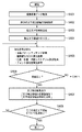
次に、図2を参照して、撮像装置101と接続された場合の位置姿勢計測装置100の機能構成の一例を説明する。 位置姿勢計測装置100は、撮像画像取得部110、画像記憶部120、文字指標検出部200、指標情報記憶部300、指標座標算出部400、及び位置姿勢推定部500から構成される。
Next, an example of a functional configuration of the position /
まず、撮像画像取得部110には、撮像装置101で現実空間を撮像して得られた画像信号が供給される。撮像画像取得部110は、取得した画像信号を、後段の画像処理が処理しやすい形にサンプリング処理する。例えば、撮像装置101から供給されたアナログ画像信号をA/D変換し、圧縮符号化する等してデジタルデータとしての撮像画像データに変換する。この撮像画像データは、画像記憶部120に格納される。これにより、撮像装置101で得られた画像信号を、計算処理しやすいデータとして取扱うことができる。
指標情報記憶部300は、文字・指標検出部200、指標座標算出部400及び位置姿勢推定部500が参照可能なデータベースである。指標情報記憶部300には、指標対象の文字領域のテンプレート画像などの文字認識処理の際に類似度計算に用いる情報および該指標の現実空間における位置情報又は配置情報(3次元座標情報)が登録されている。具体的には、検出に必要な文字情報、検出対象となる文字領域の周辺の画像情報、指標や文字領域周辺の画像情報から抽出可能な色度・彩度・明度、輪郭線、及び、幾何学的な特徴等が登録されている。さらに、文字以外の指標の指標の検出に必要な情報も予め登録されている。なお、指標情報記憶部300の登録内容は、これらに限定されるものではない。なお、撮像画像データには、撮像装置101の撮影姿勢に応じて歪みが発生する。そこで、予め複数の姿勢に対応した画像を撮影しておき、該画像を文字画像のテンプレートとして指標情報記憶部300に登録しておいてもよい。また、標準的な文字画像を、複数の撮影姿勢に対応するように演算により変形させて、複数の文字画像として指標情報記憶部300に登録してもよい。複数の撮影姿勢に対応させてテンプレートを用意することにより、撮影姿勢にかかわらず指標の検出精度を高めることができる。
First, the captured
The index
文字・指標検出部200は、指標情報記憶部300に記憶されている情報を用いて、撮像画像データから現実空間に存在する文字(例えば図1の領域102内の文字)に対応する文字領域を指標として検出する。さらに、文字・指標検出部200は、文字領域以外の他の指標も検出する。なお、本実施例において「指標」とは、現実空間内に予め配置され、かつ、現実空間における3次元座標が予め把握された、撮像装置の位置及び姿勢を算出するために使用される目印のことをいう。
The character /
指標座標算出部400は、文字・指標検出部200における文字領域や指標の検出結果に基づいて、撮像画像データにおける該文字領域や指標の位置を算出する。
The index coordinate
位置姿勢推定部500は、指標座標算出部400により算出された撮像画像中の文字領域或いは指標の位置と、現実空間における文字領域或いは指標の配置とを利用して、撮像装置101の位置姿勢600を推定し出力する。撮像装置101の位置姿勢は、例えば、現実空間における三次元座標、パン値、チルト値、回転値により表すことができる。
The position /
次に、位置姿勢計測装置100を構成する各処理部で実行される処理の具体例を説明する。
Next, a specific example of processing executed by each processing unit constituting the position /
<文字・指標検出部200>
文字・指標検出部200では、撮像画像取得部110から供給された撮像画像データ中に含まれる文字領域及び指標の検出処理を行う。この検出処理は、例えば以下のようにして行うことができる。なお、以下では、文字領域の検出処理を説明する。
<Character /
The character /
まず、指標情報記憶部300に保存されている文字のテンプレート画像と、撮像画像データ中の所定領域とをパターンマッチングにより比較して類似度を算出する。そして、算出された類似度が予め定められた閾値以上である場合に、該所定領域を登録文字に相当する文字領域と検出する。
First, the similarity is calculated by comparing the template image of characters stored in the index
なお、撮像画像データには、撮像装置101の撮影姿勢に応じて歪みが発生する。そこで、予め複数の姿勢に対応した画像を撮影しておき、該画像を文字画像のテンプレートとして指標情報記憶部300に登録しておいてもよい。また、標準的な文字画像を、複数の撮影姿勢に対応するように演算により変形させて、複数の文字画像として指標情報記憶部300に登録してもよい。
Note that distortion occurs in the captured image data in accordance with the imaging posture of the
文字・指標検出部200における検出処理は、上述の手法以外に以下のような手法により実行することもできる。
The detection process in the character /
一般に、文字は局所的に複数の線分が縦横に組み合わさったものである。撮像画像データから輪郭線を検出し、輪郭線の組み合わせの文字に対する類似度を算出し、類似度が予め定められた閾値以上である画像領域を文字領域として検出する。 In general, a character is a local combination of a plurality of line segments vertically and horizontally. A contour line is detected from the captured image data, a similarity to a character of a combination of contour lines is calculated, and an image region whose similarity is equal to or greater than a predetermined threshold is detected as a character region.
また、文字を構成する線分には、多くの情報が含まれる。仮に文書画像から文字を検出する場合には、紙文書をスキャナ等で読み込む際に最適な撮像条件を事前に設定し、文字の歪みなどを抑制することで、該線分に含まれる情報を活用できる。しかし、現実空間を自由に移動することを前提とした撮像装置101で撮像した撮像画像データから文字検出を行う場合には、該線分に含まれる情報を活用し、文字を含む領域を効率的に検出するためには、相応の画像処理が必要となる。
In addition, a lot of information is included in the line segment constituting the character. If characters are detected from a document image, the optimal imaging conditions are set in advance when reading a paper document with a scanner, etc., and the information contained in the line segment is used by suppressing character distortion. it can. However, when character detection is performed from captured image data captured by the
本実施例では、撮影画像から文字領域を検出するために、撮影画像における文字の輪郭線を顕著にする処理を行い、輪郭線を検出する。検出された輪郭線を統合する処理を行って文字の字画線の分離部分を結合し、文字領域を検出する。そして、検出された文字領域に対して、OCRによる文字認識を行い、該当する領域が文字領域であるかどうかを判別する。なお、本実施例では、「OCR」との語を、事前学習して生成した辞書を用いて、撮像データ中の文字を認識するための文字認識技術を意味する概念において使用する。OCRでは、検出対象となる言語で使用される文字が事前に登録された単語辞書を利用する。 In the present embodiment, in order to detect a character region from a captured image, a process for making the outline of the character in the captured image noticeable is performed to detect the contour line. A process for integrating the detected contour lines is performed to combine the separated portions of the character stroke lines to detect a character area. Then, character recognition by OCR is performed on the detected character area to determine whether or not the corresponding area is a character area. In this embodiment, the word “OCR” is used in a concept that means a character recognition technique for recognizing characters in imaged data using a dictionary generated by pre-learning. In OCR, a word dictionary in which characters used in a language to be detected are registered in advance is used.
次に、図3を参照して、OCRを利用した場合の具体的な文字検出処理の一例を説明する。 まず、ステップS300では、文字・指標検出部200が撮像画像取得部110から撮像画像データを取得する。この撮像画像データは、撮像装置の動きやレンズの焦点距離により検出対象となる文字領域がボケている場合も少なくない。このような条件下で文字の構造を推定する場合、文字を構成する字画線の構造的な組み合わせに注目することが重要であり、字画線を構成する輪郭線の方向線分などを特徴として利用することで、高精度な文字識別を行うことができる。
Next, an example of specific character detection processing when OCR is used will be described with reference to FIG. First, in step S300, the character /
そこで、顕著に輪郭線を検出するための画像処理を撮像画像データに施す。具体的には、ステップS301及びステップS302において、点の広がり関数がガウス関数で近似できるガウシアンフィルタをその分散値を互いに違えたものを用いて、ステップS300において取得した撮像画像データにフィルタ処理を施す。ステップS301における第1のガウシアンフィルタ処理では、ガウシアンフィルタの分散値をσ1とする。また、ステップS302における第2のガウシアンフィルタ処理では、ガウシアンフィルタの分散値をσ2とする。ここで設定される分散値の一例として、例えば、σ1には1.0を設定し、σ2には1.4を設定する。但し、この設定値はあくまで一例であって、画像の質や解像度に応じて変化させることが望ましい。 Therefore, image processing for significantly detecting the contour line is performed on the captured image data. Specifically, in step S301 and step S302, the captured image data acquired in step S300 is filtered using a Gaussian filter whose point spread function can be approximated by a Gaussian function with different dispersion values. . In the first Gaussian filter processing in step S301, the variance value of the Gaussian filter is set to σ1. In the second Gaussian filter process in step S302, the variance value of the Gaussian filter is set to σ2. As an example of the dispersion value set here, for example, 1.0 is set for σ1 and 1.4 is set for σ2. However, this set value is only an example, and it is desirable to change it according to the quality and resolution of the image.
次に、ステップS303では、ステップS301及びステップS302における処理結果として得られた撮像画像データの明度値を、引き算するフィルタ処理を行う。この処理により、輪郭線が存在する明度変化が大きい部分が強調され、人間の視覚特性と同様な輪郭線強調を撮影画像に対して行うことができる。 Next, in step S303, filter processing for subtracting the brightness value of the captured image data obtained as the processing results in steps S301 and S302 is performed. By this processing, a portion with a large brightness change where an outline exists is emphasized, and contour enhancement similar to human visual characteristics can be performed on a captured image.
次に、ステップS304では、ステップS303における処理結果に対し、更に零クロス領域抽出フィルタ処理を施す。この零クロス領域抽出フィルタ処理では、濃度変化が正から負、または負から正に変化する部分、つまり濃度変化の0値を通過する領域を抽出する。これにより、輪郭線部分を更に適切に抽出することができる。 Next, in step S304, zero cross region extraction filter processing is further performed on the processing result in step S303. In this zero cross region extraction filter processing, a portion where the density change changes from positive to negative or from negative to positive, that is, a region that passes the zero value of the density change is extracted. Thereby, a contour line part can be extracted more appropriately.
次に、ステップS305では、ステップS304における処理結果に対し、線分を構成していない部分の微少領域の誤検出を除去するためのノイズ除去フィルタ処理を施す。これにより、輪郭線部分を更に強調して、文字検出をより効率的に行うことができる。 Next, in step S305, a noise removal filter process is performed on the processing result in step S304 in order to remove erroneous detection of a minute region that does not constitute a line segment. Thereby, the outline portion can be further emphasized, and the character detection can be performed more efficiently.
そこで、ステップS306からステップS308では、輪郭線処理により文字領域を検出する。 Therefore, in step S306 to step S308, a character area is detected by contour processing.
現実空間には文字以外に構造物などの線分が多数含まれるため、検出された輪郭線からこれらを除外して文字を構成する線分を抽出しなくてはならない。構造物を構成する輪郭線(線分)と比較して文字を構成する輪郭線(線分)は、局所的に分布している場合が多い。建物や構造物を構成する輪郭線と、文字を構成する輪郭線とでは線分の密度が異なる。よって、線分密度の違いを利用して文字を検出することが可能である。 ステップS306では、撮像画像データ中に存在する各輪郭線閉曲線に対して、外接四角形を設定する。この設定手法の具体例を図4を参照して説明する。図4は、撮像画像データ中に存在する各輪郭線閉曲線に対して、外接四角形を設定する手法説明するための図である。図4(a)は、「た」という平仮名を斜め方向から撮像した撮像画像データから検出された輪郭線成分の一例を示している。この検出された輪郭線成分を一文字を構成する輪郭線成分として結合するために、図4(b)に示すように、検出された輪郭線の閉曲線の外接四角形を設定する。図4の例では、3つの輪郭線の閉曲線が存在し、それぞれ曲線に対して外接する四角形401、402及び403を設定する。このとき、外接四角形401乃至403は、401と402、401と403が互いに重複部分を有している。これは、上記のように、文字を構成する輪郭線は局所的に分布する傾向が高いためである。
Since the real space includes many line segments such as structures other than characters, it is necessary to extract the line segments constituting the character by excluding these from the detected outline. In many cases, the contour lines (line segments) constituting the characters are locally distributed compared to the contour lines (line segments) constituting the structure. The density of the line segment differs between the contour line constituting the building or structure and the contour line constituting the character. Therefore, it is possible to detect a character using the difference in line segment density. In step S306, a circumscribed rectangle is set for each contour closed curve existing in the captured image data. A specific example of this setting method will be described with reference to FIG. FIG. 4 is a diagram for explaining a method of setting a circumscribed rectangle for each contour closed curve existing in captured image data. FIG. 4A shows an example of a contour component detected from captured image data obtained by capturing the hiragana “ta” from an oblique direction. In order to combine the detected contour component as a contour component constituting one character, a circumscribed rectangle of the detected contour closed curve is set as shown in FIG. In the example of FIG. 4, there are three closed contour lines, and
一部の言語の文字を除いて文字列を構成する文字同士に僅かな隙間が存在する。したがって、この隙間を利用して、文字列中の文字同士を分離することができる。しかし、文字を構成する字画線が分離している場合もあるため、それらを文字単位で統合する必要がある。 ステップS307では、このように互いに重複部分を有する隣接外接四角形同士をグループ化して、結合領域を生成する。例えば、図4(c)に示すように、互いに隣接する外接四角形401から403を包含する四角形404を設定することにより、外接四角形同士が結合された結合領域を求める。本実施例では、この結合ルールを単純に外接四角形が重複、或いは、接触していることとしている。しかし、漢字の場合、偏と旁のように縦や横に分離し、必ずしも外接四角形が互いに重複したり接触しない場合もありえる。そこで、検出した外接四角形の縦横比に応じて係数を設定し、該係数を乗じた領域において接触判定を行っても良い。
Except for characters in some languages, there is a slight gap between characters constituting the character string. Therefore, it is possible to separate characters in the character string using this gap. However, since the stroke lines constituting the characters may be separated, it is necessary to integrate them in units of characters. In step S307, adjacent circumscribed rectangles having overlapping portions as described above are grouped to generate a combined region. For example, as shown in FIG. 4C, by setting a
次に、ステップS308では、ステップS307で生成された結合領域の正規化処理を行う。ここでは、例えば、図4(c)のように四角形404により結合された領域の縦横比を正規化(例えば縦横比が1対1となるように調整)する。この正規化処理の結果、図4(d)に示すような形に文字が変形される。このように正規化を行うことで、仮に撮影姿勢に基づき文字領域が歪んでいた場合であっても、当該歪みを解消することができる。このようにして、OCRの辞書との差を吸収して識別率を向上させることが可能である。
Next, in step S308, normalization processing of the combined area generated in step S307 is performed. Here, for example, as shown in FIG. 4C, the aspect ratio of the region joined by the
なお、以上の処理では、文字が回転している場合に対応するために必要となる文字の方向に関する補正を行っていない。ステップS307において以下の処理を追加的に行うことにより、OCRする際の文字画像の方向を補正することができる。まず、図4(c)に示すような領域について、輪郭線の線分方向ヒストグラムを複数方向について求め、その中でヒストグラムが最大になる方向を文字の上部とする。そして、OCRにおける事前学習においても同様な処理を施した文字列を学習させておく。これにより、撮像装置101が回転した場合にも、撮影画像における文字の方向を、予め学習した文字の方向に合わせることができる。また、文字の回転に対する補正として、ある文字の近傍に位置する他の複数の文字を統合して文字列の領域を設定し、文字列のベースライン(文字下端部を結ぶ直線)を求め、そのベースラインの傾きを用いて回転を補正しても良い。
In the above processing, correction relating to the direction of the character necessary to cope with the case where the character is rotating is not performed. By additionally performing the following processing in step S307, the direction of the character image at the time of OCR can be corrected. First, for a region as shown in FIG. 4C, a line segment direction histogram of the contour line is obtained for a plurality of directions, and the direction in which the histogram is maximum among them is the upper part of the character. And the character string which performed the same process also in the prior learning in OCR is learned. Thereby, even when the
図3のステップS309では、ステップS308において正規化された結合領域について、OCRを利用した文字認識処理を行う。一般に利用できるOCRは、紙原稿に記載された文字を画像処理により判読する環境を条件としている場合が多い。従って、本実施例のように撮像装置101の撮影方向に応じて文字の形状に歪みが発生している場合は、紙原稿と同様の辞書を用いていては識別率が低下する。そこで、上述のように文字の輪郭線に処理を施した文字に対して事前学習を行って辞書を作成しておくことで、識別率を向上できる。また、本実施例における検出対象文字は活字文字であるため、コンピュータで利用しているフォントから抽出した輪郭線情報を利用すれば、複数の文字形状を有する辞書を学習することは容易である。
In step S309 in FIG. 3, character recognition processing using OCR is performed on the combined region normalized in step S308. In general, OCR that can be generally used is subject to an environment in which characters written on a paper document are read by image processing. Therefore, when the character shape is distorted according to the shooting direction of the
ステップS309における文字認識処理では、撮像画像データ内の正規化済の各結合領域から抽出される特徴情報を順に選択し、事前学習により得られた辞書に含まれる特徴情報と比較を行う。この比較において類似度を算出し、各結合領域について最大となる類似度を算出する。 In the character recognition processing in step S309, feature information extracted from each normalized combined region in the captured image data is sequentially selected, and compared with feature information included in a dictionary obtained by pre-learning. In this comparison, the similarity is calculated, and the maximum similarity is calculated for each combined region.
続くステップS310では、ステップS309における文字認識処理の結果として出力された類似度と、予め設定された閾値とを比較する。この比較において、類似度が閾値よりも低い場合には(ステップS310において「NO」)、ステップS312の処理に移行する。この場合、文字認識対象の結合領域が、撮像画像データに含まれる構造物を構成する輪郭線(の一部)を構成するものと考えられるため、該当結合領域を破棄して、再度ステップS309に戻って、他の結合領域についての文字認識処理を行う。 In the subsequent step S310, the similarity output as a result of the character recognition process in step S309 is compared with a preset threshold value. In this comparison, when the similarity is lower than the threshold (“NO” in step S310), the process proceeds to step S312. In this case, since it is considered that the combined area for character recognition constitutes (a part of) the contour line constituting the structure included in the captured image data, the corresponding combined area is discarded and the process returns to step S309. Returning, the character recognition process is performed for the other combined areas.
一方、類似度が閾値以上の値を有する場合には(ステップS310において「YES」)、ステップS311の処理に移行する。ステップS311では、文字検出結果が指標座標算出部400へ出力される。このとき、指標座標算出部400には、検出された文字領域に関する情報が出力される。
On the other hand, if the similarity has a value equal to or greater than the threshold (“YES” in step S310), the process proceeds to step S311. In step S <b> 311, the character detection result is output to the index coordinate
次に、ステップS313では、ステップS308において正規化処理された全ての結合領域について処理が完了したか否かを判定する。もし、処理が完了した場合は(ステップS313において「YES」)、本処理を終了する。一方、未処理の結合領域が残っている場合には(ステップS313において「NO」)、ステップS309に戻って処理を継続する。 Next, in step S313, it is determined whether or not the processing has been completed for all the combined regions that have been normalized in step S308. If the process is completed (“YES” in step S313), this process ends. On the other hand, if an unprocessed combined area remains ("NO" in step S313), the process returns to step S309 and continues.
なお、図3に示すフローチャートに対応する処理を実行するための構成は、画像処理を行う専用の集積回路とOCRを行う判別回路を組み合わせることで実現できる。 The configuration for executing the processing corresponding to the flowchart shown in FIG. 3 can be realized by combining a dedicated integrated circuit that performs image processing and a determination circuit that performs OCR.
上記の図3に関連する文字検出処理の説明では、結合領域の生成において、主に単一文字を扱う場合を説明したが、複数の文字の集合を文字列として扱うこともできる。 In the description of the character detection processing related to FIG. 3 described above, the case where a single character is mainly handled in the generation of a combined area has been described. However, a set of a plurality of characters can also be handled as a character string.
文字は1文字のみで使用されることは少ないため、複数の文字の集合、即ち文字列の単位で管理するほうが文字認識処理における識別率を向上する上で効果的である。文字列を構成する文字同士の関連は、前述の色度や輪郭線の外接する面積などが似通った近隣部位を文字列として想定することができる。この場合、人が可読できる文字列の方向(縦書き、横書き)で無い場合もあるが、指標を識別するという目的では問題ない。 Since a single character is rarely used, it is more effective to improve the recognition rate in character recognition processing by managing a set of a plurality of characters, that is, a character string unit. The relationship between the characters constituting the character string can be assumed as a character string in the vicinity where the aforementioned chromaticity, the area circumscribed by the contour line, and the like are similar. In this case, there is a case where the direction of the character string is not human readable (vertical writing, horizontal writing), but there is no problem for the purpose of identifying the index.
さらに、撮像装置101が存在するエリア内で、ある文字と同一の文字が他に存在しない場合には、当該ある文字について指標情報記憶部300の登録情報との対応づけを行うことは比較的容易である。一方、同一エリア内に同一文字が複数存在する場合には、登録情報との対応付けが困難となる。そこで、単一の文字として扱うだけでなく、複数の文字の集合としての文字列において扱うことで、登録情報との対応付けをより容易なものとすることができる。
Furthermore, when there is no other character identical to a certain character in the area where the
文字に関連する特徴量をいずれか1つ以上組み合わせて検出することにより、処理時間を短縮する効果がある。 以下、文字の集合を文字列として扱う場合の処理について説明する。 By detecting a combination of one or more feature quantities related to characters, there is an effect of shortening the processing time. Hereinafter, processing when a set of characters is handled as a character string will be described.
撮像装置101の撮像方向と、撮像対象となる文字列が存在する平面とが正対している場合、撮像画像データ中の文字列と、文字認識処理に使用する辞書中の参照用の文字列との比較は容易に行える。しかし、撮像装置101を自由に動かして撮像を行っている状況下では、撮像装置101の撮像方向と、撮像対象となる文字列が存在する平面との位置関係は任意なものとなり、必ずしも正対しているとは限らない。この場合、図5(a)に示すように文字列を斜めから撮影することとなる場合が多い。図5(a)は、撮像装置101が文字を含む領域102を斜めから撮影している状態を一例として示す図である。なお、図5は、撮像装置101が文字を含む領域102を斜めから撮影している場合の、文字の歪みを解消するための手法を説明するための図である。
When the imaging direction of the
図5(a)のような状態で撮像された撮像画像データの一例を図5(b)に示す。図5(b)では、撮像装置101により撮像された撮像画像データ500には、文字を含む領域102が撮影位置の関係で歪んで投影されている。即ち、撮像画像データには、撮像装置101の近傍に位置する文字が大きく投影され、撮像装置101から遠くに位置する文字ほど小さく投影されている。このような歪みを補正するために、いかのような処理を行うことができる。
An example of captured image data captured in a state as shown in FIG. 5A is shown in FIG. In FIG. 5B, the
まず、上記の図3のフローチャートのステップS307における隣接外接四角形の結合結果を利用し、互いに接触或いは重複してはいないが、互いに距離の近い結合領域の集合を文字列として見なす。そして、結合領域の矩形に接する線を、頂点501と頂点502を結ぶ線分505と、頂点503と頂点504とを結ぶ線分506のように設定する。このとき、線分の端点、つまり頂点501乃至504の画面横方向の位置(点線507、508で示す位置)を、結合領域を含む矩形の左右の端辺と一致させることで、文字領域のみを取り扱うことができる。
First, the result of combining adjacent circumscribed rectangles in step S307 in the flowchart of FIG. 3 is used, and a set of combined regions that are not touching or overlapping each other but are close to each other is regarded as a character string. Then, the line in contact with the rectangle of the combined area is set as a
次に、文字を含む領域が外接している頂点501乃至504で囲まれた四角形に対して台形歪み補正を行って、該四角形の形状を矩形形状に補正する。この台形歪み補正は、当業者には周知の技術であるので、簡単のために本明細書ではその詳細に関する説明を省略する。図5(c)は、この台形歪み補正後の画像510を示す図である。図5(c)において、画像510は、頂点501乃至504に対応する、頂点511乃至514で構成される長方形領域を含んでいる。長方形領域内に含まれる各文字は、撮影条件に基づく歪みが台形歪み補正により解消されている。このようにして結合領域の集合を文字列として扱うと共に、撮影姿勢に基づく文字の歪みを解消することができる。
Next, trapezoidal distortion correction is performed on the quadrangle surrounded by the
以上の処理は、ステップS308における結合領域の正規化処理において併せて行うことができる。これにより、後段のステップS309以降の文字認識処理における識別率を更に向上させることが可能となる。 The above processing can be performed together in the normalization processing of the combined area in step S308. As a result, it is possible to further improve the recognition rate in the character recognition process after step S309.
なお、図5(b)の撮像画像データ500に台形歪み補正を行って得られた図5(c)のような撮像画像データ510を、文字認識処理の際に利用する登録画像として用いることもできる。また、元画像に画像変形を施して、複数の撮影姿勢を想定したテンプレートを画像登録時に生成し、該元画像との対応づけて登録しておくこともできる。このようにすることで、撮像装置の姿勢の変化に基づく画像の歪みによる文字認識の識別率低下を効果的に低減させることができる。なお、画像変形の手法としては、アフィン変形や平面ホモグラフィーの関係式を用いた変形を適用することができる。
Note that the captured
<指標情報算出部400>
次に、指標座標算出部400について説明する。指標座標算出部400は、文字指標検出部200によって検出された文字領域から、撮像画像データ上で指標となる文字が投影された位置の情報を算出する。
<Indicator
Next, the index coordinate
図7及び図8を参照して、指標情報算出部400における処理の一例を説明する。以下では、特に、文字・指標検出部200において検出された文字、及び、周辺の画像情報を利用して、現実空間における指標の、撮像画像データ上での位置を算出する例を説明する。図7は、指標情報算出部400における処理を説明するための、指標の具体例及び該指標を撮像して得られた撮像画像データの一例を示す図である。図8は、指標情報算出部400における処理の一例を示すフローチャートである。
An example of processing in the index
例えば、図7(a)に示すように、非常口を示す掲示物を指標として使用する場合を考える。この場合、指標情報記憶部300には、該掲示物のテンプレート画像701と共に、「EXIT」中の4つのアルファベット文字と、該4文字を結合させた文字列及びその周辺の画像がテンプレート画像として登録される。指標情報記憶部300はまた、テンプレート画像について、現実空間における位置情報(三次元座標)を関連づけて登録している。位置情報は、例えばテンプレート画像の重心位置である。なお、重心位置は、例えば、図7(c)に示すようにテンプレート画像701の頂点を結んで構成される対角線の交点の位置である。
For example, as shown in FIG. 7A, consider a case in which a posting showing an emergency exit is used as an index. In this case, in the index
指標座標算出部400は、ステップS801において、文字・指標検出部200において検出された文字等の検出結果を取得する。そして、ステップS802において取得した検出結果の内容に従い、指標情報記憶部300に登録されているテンプレート画像701を選択する。
In step S <b> 801, the index coordinate
続くステップS803では、選択したテンプレート画像701を用いて、撮像画像データとのマッチング処理を行い、類似度を算出する。この結果、類似度が閾値以上となるマッチング位置が発見できれば(ステップS804において「YES」)、ステップS808に移行する。ステップS808では、類似度が閾値以上となるマッチング位置に基づいて、撮像画像データにおける指標の位置情報を、位置姿勢推定部500に出力する。現実空間における指標の位置情報と対応する撮影画像データにおける位置情報、本実施例では、指標における重心位置に対応する撮像画像上の位置情報を出力する。
In the subsequent step S803, using the selected
一方、類似度が閾値以上となるマッチング位置が発見できない場合(ステップS804において「NO」)、ステップS805に移行する。 On the other hand, if a matching position where the similarity is equal to or greater than the threshold cannot be found (“NO” in step S804), the process proceeds to step S805.
図7(a)に示すような掲示物としての領域102は、一般には人目に付きやすい位置に配置されているが、撮像装置101の姿勢位置によっては、壁や構造物により一部が隠蔽され、撮像画像データに全体が含まれない場合がある。例えば、図7(b)に示すように、撮像画像データ710中において、非常口を示す掲示物711の一部が、ドア712によって隠蔽されてしまう場合がある。このような状態で、掲示物に係るテンプレート画像701を用いてマッチングを行おうとしても、撮像画像データ710中の掲示物711は、登録情報とは姿勢や大きさが異なると共に、一部が隠蔽されている点で対応付けが困難である。その結果、類似度が閾値を上回らないこととなる。
Although the
この場合、ステップS805において、撮像画像データ710中で、テンプレート画像701に対応する文字などが検出された部分領域711から、テンプレート画像701に含まれる領域を4点以上算出する。ここで、部分領域711には、文字が含まれるので、文字の字画線を構成する輪郭線の鋭角部分の頂点座標を用いて、テンプレート画像701に含まれる領域を容易に4点以上求めることができる。
In this case, in step S805, four or more regions included in the
次に、ステップS806では、平面ホモグラフィーの関係から撮像画像データとテンプレート画像701の2つの画像間の関係式を求める。
In step S806, a relational expression between the two images of the captured image data and the
ここで、平面ホモグラフィーの関係式を求めるための手順を示す。撮像装置101の内部パラメータとしての焦点距離やレンズの歪みなどは既知として、焦点距離を1とした正規化カメラとする。また、対象となる指標は三次元平面の上に構成されているものとする。テンプレート画像701を撮影したカメラ位置における指標文字を構成する点Pのカメラ座標系での位置をM'とする。また、撮像画像データを撮影した撮像装置101の姿勢Mは、テンプレート画像701を撮影した姿勢から回転行列Rを乗じ平行移動tを加えたカメラ座標系において、
M=RM’+t・・・(式1)
で表される。
Here, a procedure for obtaining a relational expression of planar homography will be described. It is assumed that the focal length, lens distortion, and the like as internal parameters of the
M = RM ′ + t (Formula 1)
It is represented by
ここで、点Pを含む平面の法線ベクトルnと、カメラ座標系の座標原点から平面までの距離をdとすれば、撮像画像撮影時のカメラ座標系における平面の方程式は、
nTM’=d・・・(式2)
となる。これを(式1)に代入すると
M=(R+tnT/d)M’・・・(式3)
が得られる。M、M’のかわりに2台の正規化カメラにおけるディジタル画像座標m、m’を用いると以下の平面ホモグラフィーの関係式が求められる。
Here, if the normal vector n of the plane including the point P and the distance from the coordinate origin of the camera coordinate system to the plane are d, the equation of the plane in the camera coordinate system at the time of taking a captured image is
n T M ′ = d (Expression 2)
It becomes. Substituting this into (Equation 1) M = (R + tn T / d) M ′ (Equation 3)
Is obtained. If digital image coordinates m and m ′ in two normalized cameras are used instead of M and M ′, the following relational expression for plane homography can be obtained.
sm=Hm’・・・(式4)
ただし、sはスカラーとし、Hは次式のような式となる
H=A(R+tnT/d)(A’)−1・・・(式5)
A、A’は、カメラの内部パラメータを示す行列であり、事前に求めておく。この式より、R、t、n、dの未知パラメータが8つなので、同一三次元平面上に存在する対応する4点が撮像画像に射影されている2つの撮像画像の姿勢の関係を求めることができる。
sm = Hm ′ (Formula 4)
Here, s is a scalar, and H is an expression such as the following expression: H = A (R + tn T / d) (A ′) −1 (Expression 5)
A and A ′ are matrices indicating the internal parameters of the camera and are obtained in advance. From this equation, since there are eight unknown parameters of R, t, n, and d, the relationship between the postures of two captured images in which the corresponding four points existing on the same three-dimensional plane are projected on the captured image is obtained. Can do.
次に、ステップS807では、テンプレート画像701の重心位置721を平面ホモグラフィーの関係式により撮像画像データ710上に投影し、撮影画像データ711における指標である文字領域の重心位置722を求める。例えば、図7(c)に示すように、テンプレート画像701の重心位置721に対応する撮像画像データ710中の部分領域711の位置722を求めることができる。
Next, in step S807, the
ステップS808では、撮像画像データ711上で求めた撮影画像の指標である文字領域の重心722の位置情報を、指標の位置情報として位置姿勢推定部500に出力する。
In step S808, the position information of the center of
なお、指標情報記憶部300には、掲示物701を複数の撮影姿勢から観察した状態を想定して画像変形を施したうえで、テンプレート画像701を登録しておくことが望まし。この画像変形として、平面ホモグラフィーの関係式を利用した画像変形を行う場合、撮影角度と距離に相当するスケールのパラメータが得られる。そこで、これらの撮影姿勢のパラメータを変形後の画像と対応付けて登録しておくのが好ましい。画像変形にはアフィン変形で処理しても精度は落ちるが同様な効果が得られる。
It should be noted that it is desirable to register the
<位置姿勢推定部500>
位置姿勢推定部500は、指標座標算出部400により算出された撮像画像中の文字領域或いは指標の位置と、現実空間における文字領域或いは指標の配置とを利用して、撮像装置101の位置姿勢600を推定し出力する。位置姿勢推定部500は、撮像装置101の位置姿勢600を推定し、該推定に基づき撮像画像中に投影される指標の位置と、指標座標算出部400により得られた画像中の指標の位置との誤差が少なくなるように、推定した位置姿勢を最適化していく。
<Position and
The position /
例えば、検出された複数の文字領域の図形の重心位置を指標の投影座標として特開2003−222509号で開示されている複数の指標による撮像装置の位置姿勢推定手法を用いることにより撮像装置の位置姿勢を推定が可能である。また、指標として1文字しか検出されていない場合でも、文字の字画線を構成する端点部を4点以上対応付けができれば、同様の手法で撮像装置101の位置姿勢推定を行うことができる。
For example, the position of the imaging device can be determined by using the position and orientation estimation method of the imaging device based on a plurality of indices disclosed in Japanese Patent Laid-Open No. 2003-222509, using the detected barycentric positions of the graphics of the plurality of character regions as projected coordinates of the indices. Posture can be estimated. Even when only one character is detected as an index, the position and orientation of the
さらに、位置姿勢推定部500では、現実空間での位置情報が既知の指標が撮像画像データに投影された位置との対応さえとれていれば良い。よって、利用環境が事前に指標が設置できる場所においては、他の幾何学的または色彩的に特徴を有する指標と併用することも可能である。
Furthermore, the position /
以上のように、本発明によれば、現実空間に既に存在している掲示物中の文字を検出し指標として利用することで、事前に指標が設置が困難な街中などの広域な場所においても撮像装置の位置姿勢を計測することが可能となる。 As described above, according to the present invention, even in a wide area such as a city where it is difficult to set an index in advance by detecting characters in a posting that already exists in the real space and using it as an index. It becomes possible to measure the position and orientation of the imaging apparatus.
[実施例2]
次に、実施例2として、文字・指標検出部200における他の処理例を説明する。なお、実施例1と同一の構成および処理については説明を割愛する。
[Example 2]
Next, another example of processing in the character /
実施例1の文字・指標検出部200における文字認識処理では、多数の輪郭線が検出された場合には、その分だけ処理時間が増加する。また、複数の言語を用いて文字認識処理する必要がある場合には、指標情報記憶部300における検索時間も増加する。これらの処理時間の増加は、位置姿勢計測装置100を複合現実感技術で利用するうえで、問題となる場合もある。
例えば、複合現実感提示システムでは、撮像装置101から定期的に出力される画像信号に対して、次の画像信号が出力されてくる以前に位置姿勢計測装置100内で位置姿勢を推定しなければならないという、リアルタイム性が必要である。OCRによる文字認識処理に多くの時間が費やされれば、リアルタイム性に関する要求を満たすことが困難となる。そこで、文字認識処理の高速化が必要となる。
In the character recognition process in the character /
For example, in the mixed reality presentation system, the position / orientation must be estimated in the position /
一般に、指標対象である文字を有する掲示物は、文字が他の画像や線分等の文字周辺情報と組み合わされている場合が多く、指標を特定する際には、文字だけでなくこれらの文字周辺情報を利用できる。このような文字周辺情報は、撮像装置101の撮像位置及び撮像解像度の関係で撮像画像データ中の文字がつぶれてしまい、OCRによる文字認識処理が行えない場合にも有用である。
In general, postings that have characters that are the target of the index are often combined with character peripheral information such as other images and line segments. Peripheral information is available. Such character peripheral information is also useful when characters in the captured image data are crushed due to the relationship between the imaging position and imaging resolution of the
このように、文字のみならず、文字の周辺に存在する画像や線分の情報を利用することで、文字のみの情報に基づいて文字認識処理を行うよりも、より迅速に文字認識処理を行うことができる。よって、リアルタイム性の要求を満たすことができる。そこで、指標情報記憶部300には、文字指標検出部200により検出される文字の情報だけではなく、文字周辺情報を併せて登録しておく。これにより、文字指標検出部200では、画像のパターンマッチングを利用した文字検出が可能となる。
Thus, by using not only characters but also images and line segment information existing around characters, character recognition processing is performed more quickly than character recognition processing based on only character information. be able to. Therefore, the real-time requirement can be satisfied. Therefore, not only the character information detected by the character
以下、図6を参照して、本実施例に対応する、文字・指標検出部200における文字検出処理の一例を説明する。図6は、本実施例に対応する文字検出処理の一例を示すフローチャートである。
Hereinafter, an example of character detection processing in the character /
図6において、ステップS601では、文字・指標検出部200が撮像画像取得部110より撮像画像データを取得する。この撮像画像データには、現実空間に存在する掲示板中の文字情報を含む領域102が投影されているものとする。
In FIG. 6, in step S <b> 601, the character /
ここで、撮像装置101の動きを、撮像速度(通常は、毎秒30フレーム)に対して微少な動きであると仮定した場合、直近の撮像装置101と現在の撮像装置101とで撮像される領域は、それほど移動していないと考えられる。よって、現在の撮像位置において撮像装置101により撮像された撮像画像データ中の文字領域も、直近に処理された撮像画像データ中の文字領域の位置からそれほどずれていないと推測できる。
Here, when it is assumed that the movement of the
そこで、ステップS602において、直近に行われた文字検出処理における文字検出領域の情報を取得する。実施例2の文字・指標検出部200は、文字検出領域保持部を備えており、ここには直近に処理された撮像画像データにおける検出結果に対応する文字検出領域の情報が保持されている。ステップS602では、この文字検出領域保持部から文字検出領域の情報を取得する。
Therefore, in step S602, information on the character detection area in the most recent character detection process is acquired. The character /
続くステップS603では、文字が存在すると推定される領域(推定文字領域)を設定する。まず、位置姿勢推定部500により取得した撮像装置101のそれ以前の位置姿勢の情報に基づき、撮像装置101の移動速度などを導出して現時点における撮像装置101の位置姿勢を推定する。次に、推定した位置姿勢に基づき、ステップS602において取得した直近に文字検出された領域を拡張して、推定文字領域を設定する。なお、位置姿勢の推定には、例えばカルマンフィルターを用いて誤差を含んだ状態での推定が実行できる。
In a succeeding step S603, an area (estimated character area) where a character is estimated to exist is set. First, based on the position and orientation information of the
次に、ステップS604では、ステップS603において設定された領域を、撮像画像データから切り出す処理を行う。これにより、撮像画像データの全体を対象として文字検出処理を行うよりも、少ない処理で済むため処理時間の短縮が期待できる。 Next, in step S604, a process for cutting out the area set in step S603 from the captured image data is performed. Accordingly, it is possible to expect a reduction in processing time because less processing is required than when character detection processing is performed on the entire captured image data.
続くステップS605では、複数の類似度算出処理を利用して類似度を総合的に算出する。具体的に、類似度算出処理として、画像パターンマッチング処理、輪郭線方向分布算出処理、色度・彩度・明度ヒストグラム算出処理、及び、フォント類似度算出処理を行うことができる。 In the subsequent step S605, the similarity is comprehensively calculated using a plurality of similarity calculation processes. Specifically, image pattern matching processing, contour direction distribution calculation processing, chromaticity / saturation / lightness histogram calculation processing, and font similarity calculation processing can be performed as similarity calculation processing.
まず、画像パターンマッチング処理では、指標情報記憶部300に登録された登録画像と、ステップS604において切り出した推定文字領域の画像との相関を、類似度として算出する。輪郭線方向分布算出処理では、切り出された推定文字領域の画像に含まれる輪郭線の方向及び量を算出し、指標情報記憶部300に登録された登録画像における輪郭線の方向及び量との比較を行い類似度を算出する。このとき、輪郭線を明確化するために図3のステップS301からS305までの処理を行うことができる。なお、ステップS301からステップS305までの処理は、ステップS601における撮像画像データ取得後に予め行っておいても良い。
First, in the image pattern matching process, the correlation between the registered image registered in the index
色度・彩度・明度ヒストグラム算出処理では、切り出した推定文字領域の画像中に含まれる色彩的な特徴量を算出し、指標情報記憶部300に登録された登録画像の特徴量との比較を行い類似度を算出する。フォント類似度算出処理では、切り出した推定文字領域の画像中の、輪郭線で構成される形状と、指標情報記憶部300に登録された特定のフォントの文字形状との類似度を算出する。
In the chromaticity / saturation / lightness histogram calculation processing, the chromatic feature amount included in the image of the estimated character region extracted is calculated and compared with the feature amount of the registered image registered in the index
次に、ステップS606では、ステップS605において算出された類似度を、各処理毎に予め設定されている閾値と比較する。もし、類似度が閾値以上の場合は(ステップS606において「YES」)、ステップS604において切り出された推定文字領域に、類似度を算出する基準となった所定の文字列が存在していると判定できる。そこで、ステップS607に移行して、文字検出結果の出力を行う。このとき併せて、文字検出領域の撮像画像データにおける位置情報を、文字検出領域保持部に登録する。 Next, in step S606, the similarity calculated in step S605 is compared with a threshold set in advance for each process. If the similarity is equal to or higher than the threshold (“YES” in step S606), it is determined that a predetermined character string serving as a reference for calculating the similarity exists in the estimated character region cut out in step S604. it can. Therefore, the process proceeds to step S607, and the character detection result is output. At the same time, the position information in the captured image data of the character detection area is registered in the character detection area holding unit.
次に、ステップS608では、ステップS604において切り出された全ての推定文字領域の画像について処理が完了したか否かを判定する。もし、処理が完了した場合は(ステップS608において「YES」)、本処理を終了する。一方、未処理の画像が残っている場合には(ステップS608において「NO」)、ステップS605に戻って処理を継続する。 Next, in step S608, it is determined whether or not the processing has been completed for all the estimated character area images cut out in step S604. If the process is completed (“YES” in step S608), this process ends. On the other hand, if an unprocessed image remains (“NO” in step S608), the process returns to step S605 and continues.
一方、類似度が閾値より小さい場合は(ステップS605において「NO」)、撮像装置101の姿勢が急激に変化して、推定文字領域内に文字が存在しなくなったことが考えられる。そこで、図3のステップS301以降の文字認識処理を行う。
On the other hand, if the degree of similarity is smaller than the threshold (“NO” in step S605), it is conceivable that the posture of the
以上のようにして、既に行われた文字検出結果を利用して効率的に文字検出を行うことができる。なお、上記では、類似度算出のために、画像パターンマッチング処理、輪郭線方向分布算出処理、色度・彩度・明度ヒストグラム算出処理、及び、フォント類似度算出処理を行う場合を説明した。これに限らず、例えば以下のような特徴量を利用して、文字領域の検出を有効に行うことも可能である。 As described above, it is possible to efficiently detect characters by using the already detected character detection result. In the above description, the case where image pattern matching processing, contour direction distribution calculation processing, chromaticity / saturation / lightness histogram calculation processing, and font similarity calculation processing are performed for similarity calculation has been described. However, the present invention is not limited to this, and for example, it is possible to effectively detect a character region by using the following feature amount.
例えば、撮像した文字が撮像画像データ中に大きく映される場合や、撮影姿勢により文字の一部が隠蔽された場合でも、文字を構成する輪郭線の部分的な特徴の適合性を判断することで、不完全な部分を補って、文字領域を検出することができる。このためには、指標情報記憶部300に、文字検出時に使用するための文字の輪郭線の情報を登録しておく必要がある。
For example, the suitability of partial features of the contour lines that make up a character is determined even when the captured character is displayed in the captured image data or when a part of the character is hidden by the shooting posture. Thus, it is possible to detect the character region by compensating for the incomplete part. For this purpose, it is necessary to register in the index
また、掲示板に使用される部分的な文字列は、同一のフォントが利用されている場合が多く、デザイン的な共通点も多数ある。従って、文字列のうち1文字文のフォントが特定できれば、他の文字については別のフォントの文字との類似度の算出を省略することができる。そこで、指標情報記憶部300では、登録されている文字情報をフォント別に分類しておくことで、検索効率を効果的に向上させることができる。
In addition, partial character strings used for bulletin boards often use the same font, and have many common points in design. Therefore, if the font of one character sentence can be specified in the character string, the calculation of the similarity between the other characters and the characters of another font can be omitted. Therefore, the index
さらに、文字を構成している色彩的な情報は重要である。文字の色彩は背景と分離して可読しやすい構成となっている。そこで、文字とその周辺を構成する領域の色度、彩度、明度の情報を併せて指標情報記憶部300に登録しておくことで、同一撮像画像データ内に同一の文字列が複数存在した場合であっても、指標として利用可能な文字の区別して検出することができる。
Furthermore, the color information that constitutes the characters is important. The character color is separated from the background and is easy to read. Therefore, by registering the information on the chromaticity, saturation, and brightness of the character and its surrounding area in the index
同様に、文字に隣接して存在する線分等の情報も併せて指標情報記憶部300に登録することで、看板やポスターなどの掲示物において、同一平面上に文字と線分などが存在する場合に、文字以外の指標として利用することができる。この場合、撮像距離が遠くなり、撮像画像データ中での文字領域が小さくなってしまい、文字に関する特徴抽出が困難な場合でも周辺の大域的な特徴を用いて、文字検出を行うことができる。
Similarly, by registering information such as a line segment that is adjacent to the character in the index
[実施例3]
上述の実施例では、撮像装置100の位置姿勢を推定するために利用可能な文字領域を含む指標は、位置姿勢推定部500においてカメラの位置姿勢で利用する座標系での位置が既知である必要がある。そのため、事前に測長器などにより位置を測定したものを利用するほか、印刷する時の文字の位置情報を利用することが可能である。しかし、想定したエリア以外での利用を考慮した場合、位置が既知では無い文字の取り扱いが問題になる。
[Example 3]
In the above-described embodiment, the index including the character area that can be used for estimating the position and orientation of the
図9は、文字・指標検出部200において、未登録の文字に関する情報を登録する指標文字登録部900を位置姿勢計測装置100が有する場合の構成の一例を示す図である。この指標文字登録部900は、文字や指標の三次元位置が未知の場合に、異なる視差で撮影し、検出された同一文字および指標の撮影画面上の投影位置を利用して、写真測量で用いられているバンドル調整により位置を算出する。指標文字登録部900は、この結果得られた三次元位置の情報を指標情報記憶部300に登録する。なお、バンドル調整は、カメラの位置姿勢と現実空間にある点の座標を投影画面上での誤差が小さくなるように最適化計算する手法であり、写真計測の分野では一般的な方法である。
FIG. 9 is a diagram illustrating an example of a configuration in the case where the position /
この指標文字登録部900を追加することにより、初期段階においては不定である文字指標検出の結果も、当該エリアを移動しているうちに指標として指標情報記憶部300に記憶されて、カメラの位置姿勢推定に利用できる点で効果的である。
By adding the index
また、指標文字登録部900における処理は任意の時点で実行することができるので、位置姿勢計測装置100による位置姿勢推定を実行する前の任意の時点で行うことができる。よって、例えば複数人で利用する場合などに、事前に指標文字登録部900による処理を行って、それまで道であった文字や指標の三次元位置情報を指標情報記憶部300に登録しておくことができる。また、登録された結果は、所定の通信手段を利用して共有化することが可能なので、他の利用者が指標文字登録部900による処理を実行しなくとも、位置姿勢計測装置100を利用することができる。
Moreover, since the process in the index
[実施例4]
本実施例では、上記の実施例において説明した位置姿勢計測装置を複合現実感提示システムとしての頭部装着型装置(HMD=Head Mounted Display)1000に適用した場合について説明する。図10は、位置姿勢計測装置100を頭部装着型装置(HMD=Head Mounted Display)1000に適用した場合の一例を示す図である。
[Example 4]
In the present embodiment, a case will be described in which the position / orientation measurement apparatus described in the above embodiment is applied to a head-mounted apparatus (HMD = Head Mounted Display) 1000 as a mixed reality presentation system. FIG. 10 is a diagram illustrating an example when the position /
HMD1000は、撮像装置101、姿勢検出センサ1002、及び、表示器1001を有する。HMD1000を装着したユーザーは現実空間内を移動可能である。撮像装置101は現実空間を撮像し、撮像した画像を表す信号を位置姿勢計測装置100へ出力する。姿勢センサ1002も位置姿勢計測装置100に接続されており、振動ジャイロなどの原理に基づいて、HMD1000の重力方向に対する傾斜角を計測する。表示器1001は、画像を表示することのできる表示器であり、通常は右目用、左目用の2つの表示器から構成される。
The
位置姿勢計測装置100には、仮想物体合成装置1003が接続されている。この仮想物体合成装置1003は、位置姿勢計測装置100より出力された撮像装置101の位置姿勢を基に、現実空間に重畳する仮想物体の三次元的な描画を行って撮像装置101の撮像画像データと合成して出力する装置である。例えば、グラフィックス描画装置を有するコンピュータでも実現できる。
A virtual
なお、本実施例においては、撮像装置101、姿勢センサ1002及び表示器1001が、それぞれ固定的に配置されたHMD1000を例として説明する。但し、撮像装置101と姿勢センサ1002とが固定された位置関係を有していればよく、必ずしも表示器1001は他の2つに対して固定的に配置されていなくてもよいし、HMD1000内に内蔵されていなくてもよい。
In this embodiment, the
図11は、図10に示した模式図に対応する機能構成の一例を示す図である。撮像装置101の姿勢を検出する姿勢計測装置1002は、重力方向に対する傾斜角度を検出する。文字指標検出部200と位置姿勢推定部500とにおいて、姿勢計測装置1002からの出力を補助的に用いることができる。これにより、例えば現実空間に配置されている掲示物の文字配列や配置の多くが、重力方向に対して垂直に設置されているという事実を処理の中で利用することにより、回転などに対する推定を容易に行える。また、上述の推定文字領域において文字検出を見失った場合でも、撮像装置101の姿勢の変化分を求めることにより、推定範囲を精度良く求めるのに効果的である。
FIG. 11 is a diagram illustrating an example of a functional configuration corresponding to the schematic diagram illustrated in FIG. 10. A
仮想物体合成装置1003は、位置姿勢推定装置100から撮像画像データと位置姿勢に関する信号を受信する。仮想物体合成装置1003は、仮想物体生成部11001と、仮想物体合成部1102とを有している。仮想物体生成部1101では、位置姿勢に合った仮想物体の描画を生成する。仮想物体合成部1102では、仮想物体生成部1101により生成された仮想物体を、撮像画像データと合成し、現実空間の画像と撮像装置の位置姿勢により観測される仮想物体の画像を合成して映像信号として出力する。仮想物体合成装置1003から出力される映像信号は、HMD1000に付属する表示器1001に表示して、画像をユーザーが観察することができる。このようにして、位置姿勢計測装置100を利用して複合現実感による画像をユーザーに対して提示することができる。
The virtual
[その他の実施例]
なお、実施の一例として上述の構成例を説明したが、撮像装置と位置姿勢計測装置を実施可能な装置があれば良く、本発明の処理構成を携帯電話や携帯型のコンピュータで実施するプログラムという形で処理を実行させても同じ効果が得られる。さらに、位置姿勢の計測結果を利用して、近隣の施設や場所に関する情報を提示するような2次的なサービスを実施することも可能である。
[Other Examples]
Although the above-described configuration example has been described as an example of implementation, any device that can implement the imaging device and the position / orientation measurement device is sufficient, and the processing configuration of the present invention is referred to as a program that is executed by a mobile phone or a portable computer. Even if the process is executed in the form, the same effect can be obtained. Furthermore, it is also possible to implement a secondary service that presents information on nearby facilities and places by using the position and orientation measurement results.
尚、前述した実施例の機能を実現するソフトウェアのプログラムを、記録媒体から直接、或いは有線/無線通信を用いて当該プログラムを実行可能なコンピュータを有するシステム又は装置に供給し、そのシステム或いは装置のコンピュータが該供給されたプログラムを実行することによって同等の機能が達成される場合も本発明に含む。 A software program for realizing the functions of the above-described embodiments is supplied from a recording medium directly to a system or apparatus having a computer that can execute the program using wired / wireless communication. The present invention includes a case where an equivalent function is achieved by a computer executing the supplied program.
従って、本発明の機能処理をコンピュータで実現するために、該コンピュータに供給、インストールされるプログラムコード自体も本発明を実現するものである。つまり、本発明の機能処理を実現するためのコンピュータプログラム自体も本発明に含まれる。 Accordingly, the program code itself supplied and installed in the computer in order to implement the functional processing of the present invention by the computer also realizes the present invention. That is, the computer program itself for realizing the functional processing of the present invention is also included in the present invention.
その場合、プログラムの機能を有していれば、オブジェクトコード、インタプリタにより実現されるプログラム、OSに供給するスクリプトデータ等、プログラムの形態を問わない。プログラムを供給するために記録媒体としては、例えば、フレキシブルディスク、ハードディスク、磁気テープ等の磁気記録媒体、MO、CD−ROM、CD−R、CD−RW、DVD−ROM、DVD−R、DVD−RW等の光/光磁気記録媒体、不揮発性の半導体メモリなどがある。 In that case, any program form may be used as long as it has a function of the program, such as an object code, a program realized by an interpreter, or script data supplied to the OS. As a recording medium for supplying the program, for example, a magnetic recording medium such as a flexible disk, a hard disk, a magnetic tape, MO, CD-ROM, CD-R, CD-RW, DVD-ROM, DVD-R, DVD- There are optical / magneto-optical recording media such as RW, and non-volatile semiconductor memories.
有線/無線通信を用いたプログラムの供給方法としては、コンピュータネットワーク上のサーバに本発明を形成するコンピュータプログラムそのもの、もしくは圧縮され自動インストール機能を含むファイル等、クライアントコンピュータ上で本発明を形成するコンピュータプログラムとなりうるデータファイル(プログラムデータファイル)を記録し、接続のあったクライアントコンピュータにプログラムデータファイルをダウンロードする方法などが挙げられる。この場合、プログラムデータファイルを複数のセグメントファイルに分割し、セグメントファイルを異なるサーバに配置することも可能である。 As a program supply method using wired / wireless communication, a computer program forming the present invention on a server on a computer network, or a computer forming the present invention on a client computer such as a compressed file including an automatic installation function There is a method of recording a data file (program data file) that can be a program and downloading the program data file to a connected client computer. In this case, the program data file can be divided into a plurality of segment files, and the segment files can be arranged on different servers.
つまり、本発明の機能処理をコンピュータで実現するためにプログラムデータファイルを複数のユーザに対してダウンロードさせるサーバ装置も本発明に含む。また、本発明のプログラムを暗号化してCD−ROM等の記録媒体に格納してユーザに配布し、所定の条件を満たしたユーザに対して暗号化を解く鍵情報を、例えばインターネットを介してホームページからダウンロードさせることによって供給し、その鍵情報を使用することにより暗号化されたプログラムを実行してコンピュータにインストールさせて実現することも可能である。 That is, the present invention also includes a server device that allows a plurality of users to download program data files in order to implement the functional processing of the present invention on a computer. In addition, the program of the present invention is encrypted, stored in a recording medium such as a CD-ROM, distributed to the user, and key information for decrypting the encryption for the user who satisfies a predetermined condition is obtained via a homepage via the Internet, for example. It is also possible to realize the program by downloading it from the computer and executing the encrypted program using the key information and installing it on the computer.
また、コンピュータが読み出したプログラムを実現することによって、前述した実施例の機能が実現される他、そのプログラムの指示に基づき、コンピュータ上で稼働しているOSなどが、実際の処理の一部または全部を行い、その処理によって前述した実施例の機能が実現され得る。 Further, by realizing the program read by the computer, the functions of the above-described embodiments are realized, and an OS or the like running on the computer based on an instruction of the program may be a part of the actual processing or By performing all of the above, the functions of the above-described embodiments can be realized by the processing.
さらに、記録媒体から読み出されたプログラムが、コンピュータに挿入された機能拡張ボードやコンピュータに接続された機能拡張ユニットに備わるメモリに書き込まれた後、そのプログラムの指示に基づき、その機能拡張ボードや機能拡張ユニットに備わるCPUなどが実際の処理の一部または全部を行い、その処理によっても前述した実施例の機能が実現され得る。 Furthermore, after the program read from the recording medium is written in a memory provided in a function expansion board inserted into the computer or a function expansion unit connected to the computer, the function expansion board or The CPU or the like provided in the function expansion unit performs part or all of the actual processing, and the functions of the above-described embodiments can be realized by the processing.
Claims (12)
前記画像から文字が描かれていると推定される複数の文字領域を抽出する抽出手段と、Extracting means for extracting a plurality of character regions presumed that characters are drawn from the image;
前記抽出された複数の文字領域の位置関係に基づいて、複数の文字領域をグループ化するグループ化手段と、Grouping means for grouping a plurality of character areas based on the positional relationship between the extracted character areas;
前記グループ化された複数の文字領域を包含する包含領域を設定する設定手段と、Setting means for setting an inclusion area including the plurality of grouped character areas;
前記包含領域の形状を整形することで前記文字領域を整形する整形手段と、Shaping means for shaping the character area by shaping the shape of the inclusion area;
前記整形された文字領域の文字を認識する文字認識手段と、Character recognition means for recognizing characters in the shaped character region;
前記文字が認識できた文字領域を指標として、前記撮像装置の位置姿勢を推定する位置姿勢推定手段とPosition and orientation estimation means for estimating the position and orientation of the imaging apparatus using the character area in which the character can be recognized as an index;
を備えることを特徴とする位置姿勢測定装置。A position and orientation measurement apparatus comprising:
前記現実空間を撮像装置により撮像して得られた第1の撮像画像データから、前記保持手段に保持されている文字領域を特定するための情報を用いて、文字領域を検出する検出手段と、
前記検出手段により検出された文字領域の前記第1の撮像画像データにおける画像位置情報と、前記保持手段に保持されている、該検出された文字領域に対応する位置情報とに基づき、前記撮像画像データ撮像時の前記撮像装置の位置姿勢を推定する推定手段と
を備え、
前記検出手段は、
前記撮像画像データから文字領域を検出する文字領域検出手段と、
前記検出された文字領域を指標として前記画像位置情報を検出する画像位置情報検出手段と
を備え、
前記文字領域検出手段は、
前記撮像画像データ中の輪郭線を抽出する輪郭線抽出手段と、
前記輪郭線から複数の文字候補領域を設定する設定手段と、
前記文字候補領域の大きさを正規化する正規化処理手段と、
前記正規化された文字候補領域に対して文字認識処理を行う文字認識処理手段と
を備え、文字が認識できた前記文字候補領域を前記文字領域として検出し、
前記正規化処理手段が、
前記設定された複数の文字候補領域の間の距離に基づいて、該複数の文字候補領域をグループ化するグループ化手段と、
前記グループ化された文字候補領域を包含する包含領域を設定する設定手段と、
前記包含領域の形状を整形するとともに該包含領域に含まれる文字領域を整形する整形手段と、
を備えることを特徴とする位置姿勢測定装置。 Holding means for holding information for specifying the character area and position information for the character area arranged in the real space;
Detection means for detecting a character area using information for specifying the character area held in the holding means from first captured image data obtained by imaging the real space with an imaging device;
Based on the image position information in the first captured image data of the character area detected by the detection means and the position information corresponding to the detected character area held in the holding means, the captured image Estimating means for estimating the position and orientation of the imaging device at the time of data imaging ,
The detection means includes
Character area detecting means for detecting a character area from the captured image data;
Image position information detecting means for detecting the image position information using the detected character area as an index;
With
The character area detecting means includes
Contour extraction means for extracting a contour line in the captured image data;
Setting means for setting a plurality of character candidate areas from the contour line;
Normalization processing means for normalizing the size of the character candidate area;
Character recognition processing means for performing character recognition processing on the normalized character candidate region;
And detecting the character candidate area where the character was recognized as the character area,
The normalization processing means
Grouping means for grouping the plurality of character candidate regions based on the set distance between the plurality of character candidate regions;
Setting means for setting an inclusion area including the grouped character candidate areas;
Shaping means for shaping the shape of the inclusion area and shaping a character area included in the inclusion area;
The position and orientation measuring apparatus, characterized in that it comprises a.
前記保持手段は、前記文字に関連する情報として、前記掲示物における前記文字領域の周辺の画像情報を保持し、
前記検出手段は更に、前記文字領域の周辺の画像情報を利用して前記文字領域の検出を行うことを特徴とする請求項4に記載の位置姿勢測定装置。 When the character area is included in a posting placed in the real space,
The holding means holds image information around the character area in the posting as information related to the character,
The position / orientation measurement apparatus according to claim 4 , wherein the detection unit further detects the character area using image information around the character area.
前記撮像装置により直近に撮像して得られた撮像画像データにおいて検出された文字領域の位置情報を保存する保存手段と、
前記保存されている位置情報に基づいて、前記第1の撮像画像データにおける前記文字領域に対応する画像領域を推定する領域推定手段と
を有することを特徴とする請求項4又は5に記載の位置姿勢測定装置。 The detection means includes
Storage means for storing the position information of the character area detected in the captured image data obtained by the latest imaging by the imaging device;
Based on the position information that is the storage position according to claim 4 or 5, characterized in that it has a first region estimating means for estimating an image area corresponding to the character area in the captured image data Attitude measurement device.
請求項4乃至7のいずれか1項に記載の位置姿勢測定装置と、
前記撮像装置において現実空間を撮像して得られた撮像画像データと、前記撮像画像データに基づいて推定された前記撮像装置の姿勢位置とに基づき、前記撮像画像データに仮想物体を合成して合成画像データを生成する仮想物体合成手段と、
前記合成画像データを表示する表示手段と
を備えることを特徴とする複合現実感提示システム。 An imaging device;
The position and orientation measurement apparatus according to any one of claims 4 to 7 ,
Based on the captured image data obtained by imaging the real space in the imaging device and the posture position of the imaging device estimated based on the captured image data, a virtual object is synthesized with the captured image data and synthesized. A virtual object synthesis means for generating image data;
A mixed reality presentation system comprising display means for displaying the composite image data.
前記位置姿勢推定装置の抽出手段が、前記画像から文字が描かれていると推定される複数の文字領域を抽出する抽出工程と、An extraction step of extracting a plurality of character regions in which the extraction means of the position and orientation estimation device is estimated that characters are drawn from the image;
前記位置姿勢推定装置のグループ化手段が、前記抽出された複数の文字領域の位置関係に基づいて、複数の文字領域をグループ化するグループ化工程と、A grouping step in which a grouping unit of the position and orientation estimation device groups a plurality of character regions based on a positional relationship between the extracted character regions;
前記位置姿勢推定装置の設定手段が、前記グループ化された複数の文字領域を包含する包含領域を設定する設定工程と、A setting step in which the setting unit of the position / orientation estimation apparatus sets an inclusion area including the grouped character areas;
前記位置姿勢推定装置の整形手段が、前記包含領域の形状を整形することで前記文字領域を整形する整形工程と、A shaping step of shaping the character area by shaping the shape of the inclusion area by shaping means of the position and orientation estimation device;
前記位置姿勢推定装置の文字認識手段が、前記整形された文字領域の文字を認識する文字認識工程と、A character recognition step in which the character recognition means of the position and orientation estimation device recognizes characters in the shaped character region; and
前記位置姿勢推定装置の位置姿勢推定手段が、前記文字が認識できた文字領域を指標として、前記撮像装置の位置姿勢を推定する位置姿勢推定工程とA position and orientation estimation step in which the position and orientation estimation means of the position and orientation estimation apparatus estimates the position and orientation of the imaging apparatus using a character area in which the character can be recognized as an index;
を有することを特徴とする位置姿勢測定方法。A position and orientation measurement method characterized by comprising:
検出手段が、前記現実空間を撮像装置により撮像して得られた第1の撮像画像データから、前記保持手段に保持されている文字領域を特定するための情報を用いて、文字領域を検出する検出工程と、
推定手段が、前記検出工程において検出された文字領域の前記第1の撮像画像データにおける画像位置情報と、前記保持手段に保持されている、該検出された文字領域に対応する位置情報とに基づき、前記撮像画像データ撮像時の前記撮像装置の位置姿勢を推定する推定工程と
を有し、
前記検出工程は、
文字領域検出手段が、前記撮像画像データから文字領域を検出する文字領域検出工程と、
画像位置情報検出手段が、前記検出された文字領域を指標として前記画像位置情報を検出する画像位置情報検出工程と
を有し、
前記文字領域検出工程は、
輪郭線抽出手段が、前記撮像画像データ中の輪郭線を抽出する輪郭線抽出工程と、
設定手段が、前記輪郭線から複数の文字候補領域を設定する設定工程と、
正規化処理手段が、前記文字候補領域の大きさを正規化する正規化処理工程と、
文字認識処理手段が、前記正規化された文字候補領域に対して文字認識処理を行う文字認識処理工程と
を有し、文字が認識された前記文字候補領域が前記文字領域として検出され、
前記正規化処理工程が、
グループ化手段が、前記設定された複数の文字候補領域の間の距離に基づいて、該複数の文字候補領域をグループ化するグループ化工程と、
設定手段が、前記グループ化された文字候補領域を包含する包含領域を設定する設定工程と、
整形手段が、前記包含領域の形状を整形するとともに該包含領域に含まれる文字領域を整形する整形工程と、
を有することを特徴とする位置姿勢測定方法。 A position and orientation measurement method by a position and orientation measurement device having a holding unit that holds information for specifying a character region and position information for a character region arranged in a real space,
The detecting means detects the character area from the first captured image data obtained by imaging the real space with an imaging device, using information for specifying the character area held in the holding means. A detection process;
Based on the image position information in the first captured image data of the character area detected in the detection step and the position information corresponding to the detected character area held in the holding means. An estimation step of estimating the position and orientation of the imaging device at the time of imaging the captured image data ,
The detection step includes
A character region detection step in which a character region detection unit detects a character region from the captured image data;
An image position information detecting step for detecting the image position information by using the detected character area as an index;
Have
The character region detection step includes:
A contour line extracting unit extracts a contour line in the captured image data,
A setting step for setting a plurality of character candidate regions from the contour line; and
A normalization processing means for normalizing a size of the character candidate region; and
A character recognition processing step in which character recognition processing means performs character recognition processing on the normalized character candidate region;
And the character candidate area where the character is recognized is detected as the character area,
The normalization process includes
A grouping step for grouping the plurality of character candidate regions based on the distance between the set plurality of character candidate regions;
A setting step in which a setting unit sets an inclusion region including the grouped character candidate regions;
A shaping step for shaping a shape of the inclusion area and shaping a character area included in the inclusion area;
The position and orientation measuring method characterized in that it comprises a.
Priority Applications (2)
| Application Number | Priority Date | Filing Date | Title |
|---|---|---|---|
| JP2006214883A JP4958497B2 (en) | 2006-08-07 | 2006-08-07 | Position / orientation measuring apparatus, position / orientation measuring method, mixed reality presentation system, computer program, and storage medium |
| US11/830,654 US7965904B2 (en) | 2006-08-07 | 2007-07-30 | Position and orientation measuring apparatus and position and orientation measuring method, mixed-reality system, and computer program |
Applications Claiming Priority (1)
| Application Number | Priority Date | Filing Date | Title |
|---|---|---|---|
| JP2006214883A JP4958497B2 (en) | 2006-08-07 | 2006-08-07 | Position / orientation measuring apparatus, position / orientation measuring method, mixed reality presentation system, computer program, and storage medium |
Publications (3)
| Publication Number | Publication Date |
|---|---|
| JP2008039611A JP2008039611A (en) | 2008-02-21 |
| JP2008039611A5 JP2008039611A5 (en) | 2009-09-24 |
| JP4958497B2 true JP4958497B2 (en) | 2012-06-20 |
Family
ID=39029217
Family Applications (1)
| Application Number | Title | Priority Date | Filing Date |
|---|---|---|---|
| JP2006214883A Active JP4958497B2 (en) | 2006-08-07 | 2006-08-07 | Position / orientation measuring apparatus, position / orientation measuring method, mixed reality presentation system, computer program, and storage medium |
Country Status (2)
| Country | Link |
|---|---|
| US (1) | US7965904B2 (en) |
| JP (1) | JP4958497B2 (en) |
Families Citing this family (56)
| Publication number | Priority date | Publication date | Assignee | Title |
|---|---|---|---|---|
| DE602006014302D1 (en) * | 2005-09-12 | 2010-06-24 | Trimble Jena Gmbh | Surveying instrument and method for providing survey data using a surveying instrument |
| JP5196825B2 (en) * | 2007-03-29 | 2013-05-15 | キヤノン株式会社 | Image processing apparatus and image processing method |
| JP4891144B2 (en) * | 2007-05-08 | 2012-03-07 | キヤノン株式会社 | Image search apparatus and image search method |
| JP5115138B2 (en) * | 2007-10-17 | 2013-01-09 | 株式会社ニコン | Focus measurement device, focus measurement method and program |
| US8558942B2 (en) | 2007-10-17 | 2013-10-15 | Nikon Corporation | Focusing measurement device, focusing measurement method, and program |
| JP5111242B2 (en) * | 2008-06-04 | 2013-01-09 | キヤノン株式会社 | Image processing apparatus and method |
| JP4806435B2 (en) * | 2008-09-10 | 2011-11-02 | 日本輸送機株式会社 | Self-position recognition method and self-position recognition system using 3D model |
| JP5253066B2 (en) * | 2008-09-24 | 2013-07-31 | キヤノン株式会社 | Position and orientation measurement apparatus and method |
| KR101035739B1 (en) * | 2009-02-13 | 2011-05-20 | 전남대학교산학협력단 | Method for compensating for distortion in text recognition |
| JP5515330B2 (en) * | 2009-03-05 | 2014-06-11 | 株式会社リコー | Information processing apparatus, parts catalog generation method, parts catalog generation program |
| JP4772888B2 (en) * | 2009-03-27 | 2011-09-14 | シャープ株式会社 | Image processing apparatus, image forming apparatus, image processing method, program, and recording medium thereof |
| US8839121B2 (en) * | 2009-05-06 | 2014-09-16 | Joseph Bertolami | Systems and methods for unifying coordinate systems in augmented reality applications |
| US8525847B2 (en) * | 2009-06-01 | 2013-09-03 | Apple Inc. | Enhancing images using known characteristics of image subjects |
| JP5460341B2 (en) * | 2010-01-06 | 2014-04-02 | キヤノン株式会社 | Three-dimensional measuring apparatus and control method thereof |
| JP5424405B2 (en) * | 2010-01-14 | 2014-02-26 | 学校法人立命館 | Image generation method and image generation system using mixed reality technology |
| KR101293776B1 (en) * | 2010-09-03 | 2013-08-06 | 주식회사 팬택 | Apparatus and Method for providing augmented reality using object list |
| US20120092329A1 (en) * | 2010-10-13 | 2012-04-19 | Qualcomm Incorporated | Text-based 3d augmented reality |
| KR20120044484A (en) * | 2010-10-28 | 2012-05-08 | 삼성전자주식회사 | Apparatus and method for tracking object in image processing system |
| JP2012194705A (en) * | 2011-03-15 | 2012-10-11 | Omron Corp | Image processor, image processing method and image processing program |
| US8199974B1 (en) * | 2011-07-18 | 2012-06-12 | Google Inc. | Identifying a target object using optical occlusion |
| US20130027573A1 (en) * | 2011-07-26 | 2013-01-31 | Symbol Technologies, Inc. | Method and apparatus for auto-detecting orientation of free-form document using ocr |
| US9305361B2 (en) * | 2011-09-12 | 2016-04-05 | Qualcomm Incorporated | Resolving homography decomposition ambiguity based on orientation sensors |
| JP5973849B2 (en) | 2012-03-08 | 2016-08-23 | キヤノン株式会社 | Coordinate input device and sensor bar used for coordinate input device |
| JP5977544B2 (en) | 2012-03-09 | 2016-08-24 | キヤノン株式会社 | Information processing apparatus and information processing method |
| JP5975685B2 (en) | 2012-03-09 | 2016-08-23 | キヤノン株式会社 | Information processing apparatus and information processing method |
| JP6000579B2 (en) | 2012-03-09 | 2016-09-28 | キヤノン株式会社 | Information processing apparatus and information processing method |
| JP5875445B2 (en) | 2012-03-30 | 2016-03-02 | キヤノン株式会社 | Coordinate input device |
| CA2870480A1 (en) * | 2012-04-13 | 2013-10-17 | Lightcraft Technology Llc | Hybrid precision tracking |
| US8798357B2 (en) * | 2012-07-09 | 2014-08-05 | Microsoft Corporation | Image-based localization |
| JP6049334B2 (en) | 2012-07-12 | 2016-12-21 | キヤノン株式会社 | Detection apparatus, detection method, and program |
| JP6031293B2 (en) | 2012-08-03 | 2016-11-24 | キヤノン株式会社 | Coordinate input device, control method therefor, and program |
| US20140067869A1 (en) | 2012-08-30 | 2014-03-06 | Atheer, Inc. | Method and apparatus for content association and history tracking in virtual and augmented reality |
| JP6021531B2 (en) | 2012-08-31 | 2016-11-09 | キヤノン株式会社 | Coordinate input device, control method therefor, and program |
| JP6105092B2 (en) * | 2013-03-06 | 2017-03-29 | インテル コーポレイション | Method and apparatus for providing augmented reality using optical character recognition |
| KR102103277B1 (en) * | 2013-04-12 | 2020-04-22 | 삼성전자주식회사 | Method for managing for image an electronic device thereof |
| DE102013009288B4 (en) * | 2013-06-04 | 2016-02-04 | Testo Ag | 3D recording device, method for creating a 3D image and method for setting up a 3D recording device |
| US9928572B1 (en) | 2013-12-20 | 2018-03-27 | Amazon Technologies, Inc. | Label orientation |
| JP6440937B2 (en) * | 2013-12-24 | 2018-12-19 | 株式会社東芝 | Information association apparatus, method and program thereof |
| CN106030658B (en) * | 2014-02-27 | 2019-07-23 | 交互数字Ce专利控股公司 | For determining the method and device in the orientation of video |
| JP6208094B2 (en) | 2014-08-26 | 2017-10-04 | 株式会社東芝 | Information processing apparatus, information processing system, information processing method, and program thereof |
| US9239961B1 (en) * | 2014-09-24 | 2016-01-19 | Amazon Technologies, Inc. | Text recognition near an edge |
| JP6548920B2 (en) | 2015-03-09 | 2019-07-24 | 株式会社東芝 | INFORMATION PROCESSING APPARATUS, INFORMATION PROCESSING METHOD, AND PROGRAM |
| JP2016197145A (en) * | 2015-04-02 | 2016-11-24 | 株式会社東芝 | Image processor and image display device |
| JP2017021695A (en) | 2015-07-14 | 2017-01-26 | 株式会社東芝 | Information processing apparatus and information processing method |
| US9704245B2 (en) * | 2015-08-18 | 2017-07-11 | International Business Machines Corporation | Determining localization from images of a vicinity |
| JP6768416B2 (en) * | 2015-09-08 | 2020-10-14 | キヤノン株式会社 | Image processing device, image compositing device, image processing system, image processing method, and program |
| KR102145726B1 (en) * | 2016-03-22 | 2020-08-19 | (주) 아키드로우 | Method and apparatus for detection door image using machine learning algorithm |
| JP6858007B2 (en) * | 2016-11-28 | 2021-04-14 | キヤノン株式会社 | Image processing system, image processing method |
| US11358290B2 (en) | 2017-10-19 | 2022-06-14 | Canon Kabushiki Kaisha | Control apparatus, robot system, method for operating control apparatus, and storage medium |
| JP2019084601A (en) | 2017-11-02 | 2019-06-06 | キヤノン株式会社 | Information processor, gripping system and information processing method |
| US10943067B1 (en) * | 2018-04-25 | 2021-03-09 | Amazon Technologies, Inc. | Defeating homograph attacks using text recognition |
| EP3786844A4 (en) * | 2018-07-06 | 2021-05-05 | Rakuten, Inc. | Image processing system, image processing method, and program |
| JP7065795B2 (en) * | 2019-01-17 | 2022-05-12 | 株式会社日立製作所 | Data creation system and data creation method |
| JP7279526B2 (en) * | 2019-05-31 | 2023-05-23 | 富士通株式会社 | Analysis program, analysis device and analysis method |
| JP7468472B2 (en) | 2021-07-08 | 2024-04-16 | Jfeスチール株式会社 | Trained model generation method, recognition method, and information processing device |
| CN113723379A (en) * | 2021-11-02 | 2021-11-30 | 深圳市普渡科技有限公司 | Artificial intelligence device, visual positioning method, device and readable storage medium |
Family Cites Families (36)
| Publication number | Priority date | Publication date | Assignee | Title |
|---|---|---|---|---|
| JP2643960B2 (en) | 1987-12-18 | 1997-08-25 | キヤノン株式会社 | Character recognition method |
| JP3576570B2 (en) * | 1991-11-19 | 2004-10-13 | ゼロックス コーポレイション | Comparison method |
| US5321770A (en) * | 1991-11-19 | 1994-06-14 | Xerox Corporation | Method for determining boundaries of words in text |
| US5525883A (en) * | 1994-07-08 | 1996-06-11 | Sara Avitzour | Mobile robot location determination employing error-correcting distributed landmarks |
| JPH08214130A (en) * | 1995-02-06 | 1996-08-20 | Matsushita Electric Ind Co Ltd | Image processing unit |
| US5642442A (en) * | 1995-04-10 | 1997-06-24 | United Parcel Services Of America, Inc. | Method for locating the position and orientation of a fiduciary mark |
| US6064749A (en) * | 1996-08-02 | 2000-05-16 | Hirota; Gentaro | Hybrid tracking for augmented reality using both camera motion detection and landmark tracking |
| JP2000502479A (en) * | 1996-10-04 | 2000-02-29 | フィリップス エレクトロニクス ネムローゼ フェンノートシャップ | Online Handwritten Character Recognition Method and Apparatus Based on Feature Vectors Using Aggregation Observation Extracted from Time Series Frames |
| JP3486536B2 (en) * | 1997-09-01 | 2004-01-13 | キヤノン株式会社 | Mixed reality presentation apparatus and method |
| US6094215A (en) * | 1998-01-06 | 2000-07-25 | Intel Corporation | Method of determining relative camera orientation position to create 3-D visual images |
| US6504571B1 (en) * | 1998-05-18 | 2003-01-07 | International Business Machines Corporation | System and methods for querying digital image archives using recorded parameters |
| US6577249B1 (en) * | 1999-10-19 | 2003-06-10 | Olympus Optical Co., Ltd. | Information display member, position detecting method using the same, apparatus and method of presenting related information, and information presenting apparatus and information presenting method |
| JP4708581B2 (en) | 2000-04-07 | 2011-06-22 | キヤノン株式会社 | Coordinate input device, coordinate input instruction tool, and computer program |
| US6587783B2 (en) * | 2000-10-05 | 2003-07-01 | Siemens Corporate Research, Inc. | Method and system for computer assisted localization, site navigation, and data navigation |
| JP3406965B2 (en) * | 2000-11-24 | 2003-05-19 | キヤノン株式会社 | Mixed reality presentation device and control method thereof |
| US20040104935A1 (en) * | 2001-01-26 | 2004-06-03 | Todd Williamson | Virtual reality immersion system |
| JP4590114B2 (en) | 2001-02-08 | 2010-12-01 | キヤノン株式会社 | Coordinate input device, control method therefor, and recording medium |
| US7389181B2 (en) * | 2004-08-31 | 2008-06-17 | Visre, Inc. | Apparatus and method for producing video drive-by data corresponding to a geographic location |
| DE10159610B4 (en) * | 2001-12-05 | 2004-02-26 | Siemens Ag | System and method for creating documentation of work processes, especially in the area of production, assembly, service or maintenance |
| JP2003215494A (en) * | 2002-01-22 | 2003-07-30 | Canon Inc | Composite reality feeling presenting device and image processing method |
| JP3796449B2 (en) | 2002-01-31 | 2006-07-12 | キヤノン株式会社 | Position and orientation determination method and apparatus, and computer program |
| JP2004048674A (en) * | 2002-05-24 | 2004-02-12 | Olympus Corp | Information presentation system of visual field agreement type, portable information terminal, and server |
| JP3952896B2 (en) * | 2002-07-30 | 2007-08-01 | キヤノン株式会社 | Coordinate input device, control method therefor, and program |
| JP4250391B2 (en) * | 2002-09-13 | 2009-04-08 | キヤノン株式会社 | Index detection apparatus and index detection method |
| US7127082B2 (en) * | 2002-09-27 | 2006-10-24 | Hrl Laboratories, Llc | Active fiducials for augmented reality |
| JP4401728B2 (en) * | 2003-09-30 | 2010-01-20 | キヤノン株式会社 | Mixed reality space image generation method and mixed reality system |
| JP4502361B2 (en) * | 2003-09-30 | 2010-07-14 | キヤノン株式会社 | Index attitude detection method and apparatus |
| JP4537104B2 (en) * | 2004-03-31 | 2010-09-01 | キヤノン株式会社 | Marker detection method, marker detection device, position and orientation estimation method, and mixed reality space presentation method |
| JP2005326275A (en) * | 2004-05-14 | 2005-11-24 | Canon Inc | Information processing method and device |
| US7613361B2 (en) * | 2004-05-14 | 2009-11-03 | Canon Kabushiki Kaisha | Information processing method and device |
| JP4522140B2 (en) * | 2004-05-14 | 2010-08-11 | キヤノン株式会社 | Index placement information estimation method and information processing apparatus |
| JP4367926B2 (en) * | 2004-05-17 | 2009-11-18 | キヤノン株式会社 | Image composition system, image composition method, and image composition apparatus |
| JP2005352705A (en) * | 2004-06-09 | 2005-12-22 | Omron Corp | Device and method for pattern recognition, and character recognizing method |
| JP4689380B2 (en) * | 2004-09-28 | 2011-05-25 | キヤノン株式会社 | Information processing method and apparatus |
| US7538894B2 (en) | 2005-04-15 | 2009-05-26 | Canon Kabushiki Kaisha | Coordinate input apparatus, control method thereof, and program |
| JP4785416B2 (en) * | 2005-05-11 | 2011-10-05 | キヤノン株式会社 | Position and orientation measurement method and apparatus |
-
2006
- 2006-08-07 JP JP2006214883A patent/JP4958497B2/en active Active
-
2007
- 2007-07-30 US US11/830,654 patent/US7965904B2/en not_active Expired - Fee Related
Also Published As
| Publication number | Publication date |
|---|---|
| JP2008039611A (en) | 2008-02-21 |
| US7965904B2 (en) | 2011-06-21 |
| US20080031490A1 (en) | 2008-02-07 |
Similar Documents
| Publication | Publication Date | Title |
|---|---|---|
| JP4958497B2 (en) | Position / orientation measuring apparatus, position / orientation measuring method, mixed reality presentation system, computer program, and storage medium | |
| US11080885B2 (en) | Digitally encoded marker-based augmented reality (AR) | |
| CN101617197B (en) | Feature identification apparatus, measurement apparatus and measuring method | |
| US9448758B2 (en) | Projecting airplane location specific maintenance history using optical reference points | |
| CN104885098B (en) | Mobile device based text detection and tracking | |
| JP4739004B2 (en) | Information processing apparatus and information processing method | |
| JP4717760B2 (en) | Object recognition device and video object positioning device | |
| US7286725B2 (en) | Information presentation apparatus for suggesting a presentation accuracy of related information and information presentation method | |
| JPWO2004095374A1 (en) | Video object recognition apparatus and recognition method, video annotation giving apparatus and giving method, and program | |
| US10229543B2 (en) | Information processing device, information superimposed image display device, non-transitory computer readable medium recorded with marker display program, non-transitory computer readable medium recorded with information superimposed image display program, marker display method, and information-superimposed image display method | |
| CN109949365A (en) | Vehicle designated position parking method and system based on road surface characteristic point | |
| US20090010496A1 (en) | Image information processing apparatus, judging method, and computer program | |
| KR20130006878A (en) | Method for restoring an image of object using base marker in smart device, and smart device for restoring an image of object using the base marker | |
| JP4517003B2 (en) | Automatic road sign recognition system | |
| JP2016212784A (en) | Image processing apparatus and image processing method | |
| JP2018533121A (en) | Method and apparatus for superimposing a virtual image on a photograph of a real scene, and portable device | |
| JP5801209B2 (en) | Camera posture estimation device, program | |
| JP2005115500A (en) | Information processor and information processing method | |
| JP2011071746A (en) | Video output device, and video output method | |
| JP2005227929A (en) | Processing method for photography image of object, image display system, program and recording medium | |
| JP2005284882A (en) | Content expression control device, content expression control system, reference object for content expression control, content expression control method, content expression control program, and recording medium with the program recorded thereon | |
| JP4380376B2 (en) | Image processing apparatus, image processing method, and image processing program | |
| US9245192B2 (en) | Ad collateral detection | |
| JP2021174285A (en) | Point cloud construction device, position estimation device, point cloud construction method, position estimation method and program | |
| CN117063206A (en) | Apparatus and method for aligning virtual objects in an augmented reality viewing environment |
Legal Events
| Date | Code | Title | Description |
|---|---|---|---|
| A521 | Request for written amendment filed |
Free format text: JAPANESE INTERMEDIATE CODE: A523 Effective date: 20090807 |
|
| A621 | Written request for application examination |
Free format text: JAPANESE INTERMEDIATE CODE: A621 Effective date: 20090807 |
|
| A977 | Report on retrieval |
Free format text: JAPANESE INTERMEDIATE CODE: A971007 Effective date: 20110907 |
|
| A131 | Notification of reasons for refusal |
Free format text: JAPANESE INTERMEDIATE CODE: A131 Effective date: 20110909 |
|
| A521 | Request for written amendment filed |
Free format text: JAPANESE INTERMEDIATE CODE: A523 Effective date: 20111108 |
|
| TRDD | Decision of grant or rejection written | ||
| A01 | Written decision to grant a patent or to grant a registration (utility model) |
Free format text: JAPANESE INTERMEDIATE CODE: A01 Effective date: 20120316 |
|
| A01 | Written decision to grant a patent or to grant a registration (utility model) |
Free format text: JAPANESE INTERMEDIATE CODE: A01 |
|
| A61 | First payment of annual fees (during grant procedure) |
Free format text: JAPANESE INTERMEDIATE CODE: A61 Effective date: 20120319 |
|
| FPAY | Renewal fee payment (event date is renewal date of database) |
Free format text: PAYMENT UNTIL: 20150330 Year of fee payment: 3 |
|
| R151 | Written notification of patent or utility model registration |
Ref document number: 4958497 Country of ref document: JP Free format text: JAPANESE INTERMEDIATE CODE: R151 |