JP4745724B2 - Image processing method and image processing apparatus - Google Patents
Image processing method and image processing apparatus Download PDFInfo
- Publication number
- JP4745724B2 JP4745724B2 JP2005168403A JP2005168403A JP4745724B2 JP 4745724 B2 JP4745724 B2 JP 4745724B2 JP 2005168403 A JP2005168403 A JP 2005168403A JP 2005168403 A JP2005168403 A JP 2005168403A JP 4745724 B2 JP4745724 B2 JP 4745724B2
- Authority
- JP
- Japan
- Prior art keywords
- image
- subject
- observer
- virtual space
- processing apparatus
- Prior art date
- Legal status (The legal status is an assumption and is not a legal conclusion. Google has not performed a legal analysis and makes no representation as to the accuracy of the status listed.)
- Expired - Fee Related
Links
Images


Description
本発明は、現実空間の画像上に、仮想空間の画像を重畳させた合成画像を生成する為の技術に関するものである。 The present invention relates to a technique for generating a composite image in which a virtual space image is superimposed on a real space image.
実写風景を背景として、その上にコンピュータグラフィックス(以下、CGと記述)を重畳して体験者に対して提示し、この体験者にあたかもその場に仮想の物体が存在するかのような体験を行わせる複合現実感(Mixed Reality:MR)の技術がある。 With a live-action scene in the background, computer graphics (hereinafter referred to as CG) are superimposed on it and presented to the experiencer, and this experience is as if a virtual object exists on the spot. There is a mixed reality (MR) technology that makes
このMR技術を用いて臨場感豊かな体験を実現するためには、背景となる実写風景の上にただ単純にCGを重畳して表示するだけではなく、体験者が実際にCGで描画される仮想物体(以下、単に仮想物体と言うことがある)に触ったり操作する(しているように体感させる)といったインタラクションが重要になってくる。そして、このようなインタラクションを実現するめには、仮想物体よりも手前(前景)に仮想物体を操作する体験者の手など(以下、被写体という)を表示することが必要である。なぜなら、仮想物体よりも手前にあるべき被写体が仮想物体によって隠されてしまうと、仮想物体との距離感や現実感が破綻し、臨場感を損ねてしまうからである。 In order to realize a rich experience using this MR technology, not only simply superimposing and displaying the CG on the background of the live-action scene, but also the actual user is drawn in CG. Interactions such as touching and operating a virtual object (hereinafter sometimes simply referred to as a virtual object) are becoming important. In order to realize such interaction, it is necessary to display the hands of an experienced person who operates the virtual object (hereinafter referred to as a subject) in front of the virtual object (foreground). This is because if the subject that should be in front of the virtual object is hidden by the virtual object, the sense of distance from the virtual object and the sense of reality will break down, impairing the sense of reality.
このような課題を解決するために、出願人は特許文献1において、最前景とすべき被写体の画像をCG画像によって隠さないようにする技術を提案した。この技術は、背景と被写体とを実写画像として取得し、この実写画像から、予め手作業でシステムに登録した、CG画像より手前に表示すべき被写体(被写体検出情報としての色情報を有する領域)を被写体領域として抽出し、被写体領域にはCG画像の描画を禁止するものである。この技術により、最前景となるべき被写体がCG画像で隠されることなく、仮想物体よりも手前にあるように表示され、臨場感の高い複合現実感体験を行うことが可能となる。 In order to solve such a problem, the applicant proposed in Japanese Patent Application Laid-Open No. H11-228707 a technique for preventing the image of the subject to be the foreground from being hidden by the CG image. In this technique, a background and a subject are acquired as a live-action image, and a subject to be displayed in front of a CG image (region having color information as subject detection information) registered in the system manually from the live-action image in advance. Is extracted as a subject region, and drawing of a CG image is prohibited in the subject region. With this technique, the subject that should be the foreground is displayed so as to be in front of the virtual object without being hidden by the CG image, and a mixed reality experience with a high presence can be performed.
また、実写画像とコンピュータグラフィックス画像とを合成する従来技術として、背景領域を特定の色によって着色し、クロマキー合成によってこの背景領域をコンピュータグラフィックス画像と置き換えるものがある。このような従来技術では実写画像は背景以外の被写体に限定されていた。
特許文献1における複合現実感体験システムでは、体験者の見ている現実の風景に被写体と類似した色情報を持つ領域がほとんど存在しない場合に良好に動作する。しかしながら、体験者の見ている現実の風景に、他の体験者が存在する風景では、本来CG画像の奥にいるべき他の体験者の被写体領域(手や顔)までもCG画像の描画を禁止してしまい、他の体験者の被写体領域がCG画像よりも手前にあるかのように表示され、体験者の現実感を損なうことがあった。
The mixed reality experience system disclosed in
このような技術的背景から、体験者の手や指定した被写体領域のみ抽出するために被写体領域を実写画像より抽出した後、抽出した領域から目的とする領域(体験者の手など)を選択し、選択した領域のみに対してCG画像を描画しない処理を施し、複合現実感画像を生成することが望まれている。 From this technical background, after extracting the subject area from the live-action image in order to extract only the hands of the experienced person or the specified subject area, the target area (such as the hands of the experienced person) is selected from the extracted area. It is desired to generate a mixed reality image by performing a process of not rendering a CG image only on a selected region.
本発明は以上の問題に鑑みてなされたものであり、現実空間の画像において、仮想空間の画像を重畳させない領域を適切に特定するための技術を提供することを目的とする。 The present invention has been made in view of the above problems, and an object of the present invention is to provide a technique for appropriately specifying a region in which a virtual space image is not superimposed in a real space image.
本発明の目的を達成するために、例えば、本発明の画像処理方法は以下の構成を備える。 In order to achieve the object of the present invention, for example, an image processing method of the present invention comprises the following arrangement.
すなわち、画像処理装置が行う画像処理方法であって、前記画像処理装置が有する取得手段が、観察者と該観察者と異なる他の人物とが存在する現実空間で該観察者の一部と該他の人物とを観察者の視点から撮像した撮像画像を取得する取得工程と、前記画像処理装置が有する登録手段が、前記撮像画像において前記観察者の一部の色として判断する被写体色を登録する登録工程と、前記画像処理装置が有する抽出手段が、前記取得した撮像画像内で、前記登録された被写体色を有する被写体領域を抽出する抽出工程と、前記画像処理装置が有する導出手段が、前記抽出された被写体領域のそれぞれのサイズを求める導出工程と、前記画像処理装置が有する計測手段が、前記観察者と前記他の人物との距離を計測する計測工程と、前記画像処理装置が有する決定手段が、前記距離に基づいて、前記他の人物によって前記仮想空間の画像がマスクされず、前記観察者の一部によって前記仮想空間の画像がマスクされる被写体領域のサイズの閾値を決定する決定工程と、前記画像処理装置が有する生成手段が、前記決定された閾値より大きいサイズの前記抽出された被写体領域を前記観察者の一部とみなして、当該被写体領域により前記仮想空間の画像をマスクするマスク画像を生成する生成工程と、前記画像処理装置が有する重畳手段が、前記撮像画像に、前記マスク画像でマスクされた前記仮想空間の画像を重畳する重畳工程と、前記画像処理装置が有する出力手段が、前記仮想空間の画像を重畳された撮像画像を出力する出力工程とを有することを特徴とする。 That is, an image processing method performed by an image processing apparatus, in which the acquisition unit included in the image processing apparatus includes a part of the observer in the real space where the observer and another person different from the observer exist. An acquisition step of acquiring a captured image obtained by capturing another person from the viewpoint of the observer, and a registration color that the registration unit of the image processing apparatus determines as a partial color of the observer in the captured image is registered. A registration step, an extraction unit included in the image processing device extracts an object region having the registered subject color in the acquired captured image, and a derivation unit included in the image processing device. a derivation step of obtaining a size of each of the extracted subject region, measuring means for the image processing apparatus has found a measuring step of measuring a distance between the other person and the observer, the image processing Determining means the device has, based on the distance, the image of the virtual space by the other person is not masked, the threshold of the size of the observer's subject region image of the virtual space by a part is masked And a generation unit included in the image processing apparatus regards the extracted subject area having a size larger than the determined threshold as a part of the observer, and uses the subject area as the virtual space. a generation step of generating a mask image for masking the image, superimposing means for the image processing apparatus has found to the captured image, and superimposing step of superimposing the image of the mask by the mask image the virtual space, the image An output unit included in the processing apparatus includes an output step of outputting a captured image on which the image of the virtual space is superimposed.
本発明の目的を達成するために、例えば、本発明の画像処理装置は以下の構成を備える。 In order to achieve the object of the present invention, for example, an image processing apparatus of the present invention comprises the following arrangement.
すなわち、観察者と該観察者と異なる他の人物とが存在する現実空間で該観察者の一部と該他の人物とを観察者の視点から撮像した撮像画像を取得する取得手段と、前記撮像画像において前記観察者の一部の色として判断する被写体色を登録する登録手段と、前記取得した撮像画像内で、前記登録された被写体色を有する被写体領域を抽出する抽出手段と、前記抽出された被写体領域のそれぞれのサイズを求める導出手段と、前記観察者と前記他の人物との距離を計測する計測手段と、前記距離に基づいて、前記他の人物によって前記仮想空間の画像がマスクされず、前記観察者の一部によって前記仮想空間の画像がマスクされる被写体領域のサイズの閾値を決定する決定手段と、前記決定された閾値より大きいサイズの前記抽出された被写体領域を前記観察者の一部とみなして、当該被写体領域により前記仮想空間の画像をマスクするマスク画像を生成する生成手段と、前記撮像画像に、前記マスク画像でマスクされた前記仮想空間の画像を重畳する重畳手段と、前記仮想空間の画像を重畳された撮像画像を出力する出力手段とを有することを特徴とする。 That is, an acquisition unit that acquires a captured image obtained by capturing a part of the observer and the other person from the viewpoint of the observer in a real space where the observer and another person different from the observer exist; Registration means for registering a subject color to be determined as a part of the color of the observer in the captured image, extraction means for extracting a subject area having the registered subject color in the acquired captured image, and the extraction Deriving means for determining the size of each of the subject areas, measuring means for measuring the distance between the observer and the other person, and masking the image of the virtual space by the other person based on the distance Sarezu, determining means and, the photographic said extracted larger size than the determined threshold image of the virtual space by a part of the observer to determine the threshold value of the size of the subject region to be masked Considers region and part of the observer, and generation means for generating a mask image for masking the image of the subject region by the virtual space, the captured image, the image of the virtual space that is masked by the mask image And superimposing means for superimposing and output means for outputting a captured image on which the image of the virtual space is superimposed.
本発明の構成により、現実空間の画像において、仮想空間の画像を重畳させない領域を適切に特定することができる。 According to the configuration of the present invention, it is possible to appropriately specify an area in which an image in the virtual space is not superimposed on the real space image.
以下添付図面を参照して、本発明を好適な実施形態に従って詳細に説明する。 Hereinafter, the present invention will be described in detail according to preferred embodiments with reference to the accompanying drawings.
図1は、ユーザ(体験者)に現実空間と仮想空間とが融合した複合現実空間を体験させるための、本実施形態に係るシステムの機能構成を示すブロック図である。また、本実施形態に係るシステムでは、現実空間の画像上に仮想空間の画像を重畳させる際に、現実空間の画像中に所定の被写体が含まれている場合には、この被写体の領域に関しては常に仮想空間の画像よりも手前に表示するよう、重畳処理を制御する。なお、本実施形態ではこの所定の被写体の一例として「手」を用いる。 FIG. 1 is a block diagram showing a functional configuration of a system according to the present embodiment for allowing a user (experience person) to experience a mixed reality space in which a real space and a virtual space are fused. Further, in the system according to the present embodiment, when a virtual subject image is superimposed on a real space image and a predetermined subject is included in the real space image, the subject region is related. The superimposition process is controlled so that the image is always displayed in front of the virtual space image. In the present embodiment, “hand” is used as an example of the predetermined subject.
図1に示す如く、本実施形態に係るシステムは、ビデオカメラ101、画像入力部102、被写体領域抽出部103、カメラ位置姿勢センサ104、カメラ位置姿勢計測部105、画像生成部106、仮想空間データベース107、画像合成部108、頭部搭載型画像表示装置(以下、HMDと呼称)109、被写体色情報登録部110、被写体領域選択部111により構成されている。
As shown in FIG. 1, the system according to the present embodiment includes a
また、図2は、本実施形態に係るシステムを使用している様子を示す図である。以下、図1,2を用いて、本実施形態に係るシステムの構成について説明する。 Moreover, FIG. 2 is a figure which shows a mode that the system which concerns on this embodiment is used. Hereinafter, the configuration of the system according to the present embodiment will be described with reference to FIGS.
なお、本システムにおける体験者は一人、または複数人を想定している。つまり、図2の体験者201が椅子202に着座している状況で、他の体験者208が体験者201から見える状態で、体験者201は複合現実感空間体験を行うなどの状況が考えられる。
In addition, the experience person in this system assumes one person or multiple persons. In other words, in the situation where the
ビデオカメラ101は現実空間の動画像を撮像するものであり、図2に示す如く、HMD109に取り付けられている。ビデオカメラ101の取り付け位置は、体験者201が自身の頭部203にHMD109を装着した場合に、体験者201の目の位置に近い位置である。また、ビデオカメラ101の取り付け方向は、体験者201が自身の頭部203にHMD109を装着した場合に、体験者201の視線方向に略一致するような方向である。従ってこのビデオカメラ101は、体験者201の目の位置姿勢に応じて見える現実空間の画像を撮像するためのものとすることができる。以下の説明では、このビデオカメラ101を「視点」と呼称する場合がある。このビデオカメラ101により撮像された各フレームの画像(現実空間の画像)は順次、図1に示す画像入力部102に入力される。画像入力部102は、受けた画像のデータを画像合成部108に出力すると共に、被写体領域抽出部103にも出力する。
The
カメラ位置姿勢センサ104は、ビデオカメラ101の位置姿勢を計測するものであり、図2に示す如く、ビデオカメラ101に取り付けられている。このカメラ位置姿勢センサ104には例えば磁気センサや光学式センサ、超音波式センサなどが適用可能である。これらのセンサによる位置姿勢の計測技術に関しては周知のものであるので、これに関する説明は省略する。
The camera position and
カメラ位置姿勢センサ104により計測されたビデオカメラ101の位置姿勢を示す信号は図1に示すカメラ位置姿勢計測部105に入力され、カメラ位置姿勢計測部105により、この信号に基づいて、ビデオカメラ101の位置姿勢を示すデータが得られる。このデータは画像生成部106に出力すると共に、被写体領域選択部111にも出力する。
A signal indicating the position and orientation of the
このように、HMD109にはビデオカメラ101、カメラ位置姿勢センサ104が備わっており、体験者201の頭部203には、このようなHMD109が装着されている。また図2に示す如く、この体験者201は、椅子202に座っている。なお、同図では体験者201は椅子202に座っているものとしているが、体験者201が任意の姿勢をとっていたとしても、以下の説明の本質は特に変わらない。
As described above, the HMD 109 includes the
図1に戻って、画像生成部106は、カメラ位置姿勢計測部105から受けたデータ、及び仮想空間データベース107に格納されているデータ(仮想空間データ)を用いて、ビデオカメラ101から見える仮想空間の画像を生成する。仮想空間データベース107には、仮想空間を構成する各仮想物体の画像を生成するために必要なデータが格納されており、例えば、仮想物体がポリゴンでもって構成されている場合には、各ポリゴンの法線ベクトルデータやポリゴンの色データ、ポリゴンを構成している各頂点の座標データ、また、仮想物体に対してテクスチャマッピングする場合には、テクスチャデータなどがこの仮想空間データベース107に格納されていることになる。
Returning to FIG. 1, the
図2の場合には、207が仮想物体であるので、この仮想物体207の画像を生成するためのデータが仮想空間データベース107に格納されていることになる。この場合、画像生成部106は、ビデオカメラ101から見える仮想物体207の画像を生成することになる。なお、所定の位置姿勢を有する視点から見える仮想空間の画像を生成する為の技術については周知のものであるので、これに関する説明は省略する。
In the case of FIG. 2, since 207 is a virtual object, data for generating an image of the
画像生成部106が生成した仮想空間の画像データは画像合成部108に出力する。画像合成部108は、画像入力部102から受けた現実空間の画像上に、画像生成部106から受けた仮想空間の画像を重畳させた合成画像、即ち、複合現実空間の画像を生成し、HMD109に出力する。これにより、体験者201の眼前には視点の位置姿勢に応じて見える複合現実空間の画像が表示されることになる。
The virtual space image data generated by the
ここで、体験者201がHMD109を介して複合現実空間の画像を観察している最中に、自身の手205や他の体験者208の手210がビデオカメラ101の視界に入った場合、当然、手205、210はビデオカメラ101によって撮像されるし、HMD109に表示される複合現実空間の画像上には手205、210が表示されることになる。
Here, when the
このような場合、観察者101にとっては、自身の手205のみが前景となることが好ましいため、現実空間の画像上の手205の領域上には仮想空間の画像は重畳させないようにするが必要である。図2の場合、体験者201がHMD109を介して複合現実空間の画像を観察する際、現実物体において自身の手205のみを前景、それ以外の現実物体206a、206b、他の体験者208の手210を背景とする。
In such a case, since it is preferable for the
そのための構成として本実施形態に係るシステムは、被写体領域抽出部103、被写体色情報登録部110、被写体領域選択部111を備える。以下では、被写体領域抽出部103、被写体色情報登録部110、被写体領域選択部111の各部について説明する。
As a configuration for this purpose, the system according to the present embodiment includes a subject
被写体色情報登録部110には、手205の色を示す色データ(色情報)が予め登録されている。ここで、この色データについて説明する。被写体色情報登録部110に登録されている色データは、多次元色空間における座標値として記述することができる。一般によく知られている表色系の種類には、RGB、YIQ、YCbCr、YUV、HSV、Lu*v*、La*b*など様々なものがある(日本規格協会 JIS色彩ハンドブック)。
In the subject color
対象とする被写体の色彩特性に合わせて、適当なものを任意に用いてよいが、照明条件の相違による被写体の色彩特性の変化を相殺するために、輝度情報と色相情報とに分離する形式の表色系を用い、色相情報だけを用いることが望ましい。このような表色系の代表的なものとしてはYIQやYCbCrが一般的である。本実施形態では、YCbCr表色系を用いる。 An appropriate one may be used arbitrarily according to the color characteristics of the target subject, but in order to cancel the change in the color characteristics of the subject due to the difference in lighting conditions, the information is separated into luminance information and hue information. It is desirable to use a color system and use only hue information. Typical examples of such a color system are YIQ and YCbCr. In this embodiment, the YCbCr color system is used.
図4は、YCbCr表色系のCbCr平面における色彩分布の概要を示す図である。横軸401がCr、縦軸402がCbである。中央403は白色の領域であり、中央から周辺に向かって彩度が高くなっている。
FIG. 4 is a diagram showing an outline of the color distribution in the CbCr plane of the YCbCr color system. The
図5は、被写体の色情報をYcbCr表色系のCbCr平面における色空間座標分布501として表現した例を示す図である。
FIG. 5 is a diagram illustrating an example in which the color information of the subject is expressed as a color space coordinate
被写体の色情報は背景の色情報に含まれないものであることが望ましいが、条件によっては被写体と背景とを色によって識別しにくい場合も考えられる。このような場合には、例えば手に着色した手袋を装着するなど、被写体に対して都合の良い色を割り当てると良い。 It is desirable that the subject color information is not included in the background color information, but depending on the conditions, it may be difficult to distinguish the subject and the background by color. In such a case, a convenient color may be assigned to the subject, for example, by wearing colored gloves on the hand.
被写体色情報登録部110における色情報の登録方法としては、被写体をカメラなどで撮像することで、この被写体の画像を取得し、取得した画像を構成する各画素の画素値をCbCr平面での分布として記述した上で、色空間の各軸の座標範囲を指定する方法や、色空間を各軸について標本化し、その各点について被写体であるか否かの値を登録する方法、いわゆるルックアプテーブルを用いる等、様々な方法が考え得る。
As a color information registration method in the subject color
図1に戻って、被写体領域抽出部103は、画像入力部102から受けた画像を構成する各画素値を参照し、被写体色情報登録部110に登録されたデータが示す『手205の色』と略同じ色を示す画素値を有する画素を「手205の領域を構成する画素」であると判断する。より詳しくは、画像入力部102から受けた画像を構成する各画素が手205の領域を構成する画素であるか否かを判断し、各画素について判断結果を割り当てる。例えば手205の領域を構成する画素については「1」を割り当て、手205の領域を構成しない画素については「0」を割り当てる。
Returning to FIG. 1, the subject
図3は、手205の色に略同じ色を有する現実物体が手205のみであるような現実空間の画像301が画像入力部102から得られた場合に、この画像301から手205の領域を抽出する処理を説明する図である。
FIG. 3 shows the region of the
画像301を構成する各画素について手205の領域を構成するものであるのか否かをチェックする処理を行うと、各画素について「1」若しくは「0」の値が割り当てられるので、結果として302で示す画像を生成することができる。画像302において「白」で示した領域は「1」が割り当てられた画素群で構成された領域で、手205の領域を構成する画素群である。一方、画像302において「黒」で示した領域は「0」が割り当てられた画素群で構成された領域で、手205の領域を構成していない画素群である。このような画像302は所謂マスク画像である。このように、このマスク画像を生成することで、現実空間の画像中における手205の領域を抽出することができる。
When a process for checking whether or not each pixel constituting the
図6は、被写体領域抽出部103が行う処理のフローチャートである。図6のフローチャートは、画像入力部102から受けた画像において、画像座標が(i,j)の位置にある画素に対する処理のフローチャートであるので、実際には被写体領域抽出部103は、図6のフローチャートに従った処理を、画像入力部102から受けた画像を構成する各画素について行うことになる。
FIG. 6 is a flowchart of processing performed by the subject
先ず、画像入力部102から受けた画像内で画像座標が(i,j)の位置にある画素のRGB値をYCrCb値に変換する(ステップS601)。画像座標が(i,j)の位置にある画素のR値をR(i、j)、G値をG(i、j)、B値をB(i、j)とすると、RGB値をYCrCb値に変換する為の関数color_conversion()でもってR(i、j)、G(i、j)、B(i、j)を変換し、Y値、Cr値、Cb値を得る。
First, the RGB value of the pixel whose image coordinates are (i, j) in the image received from the
次に、ステップS601で得たY、Cr、Cbのそれぞれの値が表現する色が、被写体色情報登録部110に登録されている色データが示す色に略同じであるのか否かを判断する。例えば同図の場合には、ステップS601で得たY、Cr、Cbのそれぞれの値が表現する色が、被写体色情報登録部110に登録されている色データが示す色に略同じであるのか否かを、関数mask_func()でもって判断する。そして判断結果は、配列mask(i、j)に代入される。この配列mask(i、j)は、画像座標が(i,j)の位置にある画素が被写体の領域を構成するものであるのか否かを示す値を格納する為のものであり、上記マスク画像において画像座標が(i,j)の位置にある画素の画素値(1もしくは0)を格納する為のものである。
Next, it is determined whether or not the color represented by each value of Y, Cr, and Cb obtained in step S601 is substantially the same as the color indicated by the color data registered in the subject color
関数mask_func()による判断方法としては、例えば、Cb、Crで規定されるCbCr平面上における座標値(Cr、Cb)が、被写体色情報登録部110に登録されている被写体の色分布501の領域に属するか否かを判定する。判定結果は、例えば、被写体色分布501に属するのであれば1、属さないのであれば0と二値で表してもよいが、属する度合いを0から1までの連続値でもって表現するようにしても良い。
As a determination method using the function mask_func (), for example, coordinate values (Cr, Cb) on the CbCr plane defined by Cb and Cr are regions of the
なお、本実施形態では、画像入力部102から受けた画像を構成する各画素の画素値がRGBで表されているものとしているが、YIQやYUVで表されていても良く、その場合には、ステップS601における処理を省略し、ステップS602において(cb、cr)の代わりにそれぞれIQ空間やUV空間における座標値を用いればよい。
In the present embodiment, the pixel value of each pixel constituting the image received from the
以上説明したように、被写体領域抽出部103は、画像入力部102から受けた画像を構成する各画素が、「手」の領域を構成するものであるのか否かを示すマスク画像を生成する。
As described above, the subject
しかしここで、被写体領域抽出部103は、現実空間の画像において『手205の色』と略同じ色を有する画素については、マスク画像上では画素値が「1」となるので、この現実空間の画像内に手205の色と略同じ色を有する現実物体が手205以外にも含まれている場合には、この現実物体の領域を構成する画素もまた、マスク画像上では画素値が「1」となることに注意されたい。このような場合、マスク画像内には複数の白の領域が点在する事になる。
However, here, the subject
従って、被写体領域選択部111は、被写体色情報登録部110が生成したマスク画像中の白領域のうち何れの領域が手205の領域であるのかを特定する処理を行う。この判断処理の詳細については後述する。
Accordingly, the subject
そして被写体領域選択部111は、マスク画像内で手205の領域を特定すると、この領域を白の領域にする。即ち、手205の領域を構成する画素の画素値を「1」にする。また、手205の領域以外の領域を黒の領域にする。即ち、手205の領域以外の領域を構成する画素の画素値を「0」にする。これにより、マスク画像において、手205の領域を構成する各画素の画素値は「1」となり、手205の領域以外の領域を構成する各画素の画素値は「0」となる。即ち、このマスク画像により、手205の領域と手205以外の領域とをマスク画像を構成する各画素の画素値でもって区別することができる。このようにして生成したマスク画像は画像合成部108に出力する。
Then, when the subject
図7は、現実空間の画像上に仮想空間の画像を重畳させる際に、被写体領域選択部111が生成したマスク画像を用いて、手205の領域上に仮想空間の画像は重畳させないようにする為の処理を説明する図である。このような処理は画像合成部108によって行われる。
FIG. 7 illustrates that when a virtual space image is superimposed on a real space image, the virtual space image is not superimposed on the region of the
同図において、301は、画像入力部102から受けた画像である。画像301には、体験者201の手205が写っている。一方、701は、画像生成部106が生成した仮想空間の画像である。ここで画像合成部108によって画像301上に画像701を重畳させる際に、画像合成部108は、マスク画像302を参照する。即ち、画像301上に画像701を重畳させる際に、画像701において画像302中の手の領域(白で示した領域)に相当する部分は画像301上には描画しないようにする。これにより、画像702に示す如く、手205の領域上には常に仮想空間の画像は描画されないので、手205の領域は常に前景とすることができる。
In the figure,
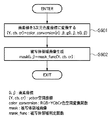
このような画像合成部108による処理を、同処理のフローチャートを示す図10を用いて説明する。図10のフローチャートは、画像入力部102から受けた画像、画像生成部106から受けた画像、において、画像座標が(i,j)の位置にある画素に対する処理のフローチャートであるので、実際には画像合成部108は、図10のフローチャートに従った処理を、i,jが取りうる範囲全てについて行うことになる。
Processing performed by the
ステップS100では、画像入力部102から受けた現実空間の画像で画像座標が(i,j)の位置にある画素の画素データreal(i,j)をフレームメモリbuffer(i,j)に転送する。次に、ステップS200では、被写体領域選択部111によって生成されたマスク画像で画像座標が(i,j)の位置にある画素の画素データmask(i,j)をマスク処理のための画像メモリであるステンシルバッファに転送する。
In step S100, the pixel data real (i, j) of the pixel having the image coordinate (i, j) in the real space image received from the
ステップS300では、画像生成部106から受けた仮想空間の画像で画像座標が(i,j)の位置にある画素の画素データCGI(i,j)を上記フレームメモリbuffer(i,j)に転送するのであるが、その際にはステンシルバッファ内の画素データmask(i,j)を参照する。
In step S300, the pixel data CGI (i, j) of the pixel whose image coordinates are (i, j) in the image of the virtual space received from the
そして、mask(i,j)=0であれば、real(i,j)は手205の領域外の領域を構成する画素データであるので、仮想空間の画像の画素データCGI(i,j)を上記フレームメモリbuffer(i,j)に転送する。これにより、フレームメモリbuffer(i,j)には、現実空間の画像の画素データreal(i,j)上に仮想空間の画像の画素データCGI(i,j)が重畳された状態で格納されていることになる。
If mask (i, j) = 0, real (i, j) is pixel data constituting an area outside the area of the
一方、mask(i,j)=1であれば、real(i,j)は手205の領域内を構成する画素データであるので、仮想空間の画像の画素データCGI(i,j)は上記フレームメモリbuffer(i,j)には転送しない。これにより、フレームメモリbuffer(i,j)には、現実空間の画像の画素データreal(i,j)のみが格納されていることになり、仮想空間の画像の画素データCGI(i,j)は重畳されない。
On the other hand, if mask (i, j) = 1, real (i, j) is the pixel data constituting the area of the
そして画像合成部108は、このようにしてフレームメモリ内に格納された画像を複合現実空間画像としてHMD109に出力する。
The
次に、被写体領域選択部111が、被写体領域抽出部103が生成したマスク画像を参照し、マスク画像内における白の領域のうち、何れの領域が手205の領域であるのかを判断する処理について説明する。
Next, a process in which the subject
上述の通り、被写体領域抽出部103は、現実空間の画像内に手205の色と略同じ色を有する現実物体が含まれている場合には、この現実物体の領域を構成する画素もまた、手205の領域を構成する画素であると判断するので、マスク画像内には複数の白の領域が点在する事になる。このようなマスク画像を用いて複合現実空間画像を生成すると、仮想空間の画像においてマスク画像中の白の領域に対応するいくつかの箇所が現実空間の画像上に描画されないことになる。しかし、目的は被写体としての手205の領域のみが前景となればよいので、マスク画像内で手205の領域以外は黒の領域とする処理が必要となる。
As described above, when a real object having substantially the same color as the color of the
図8は、このような目的のために、マスク画像において手205の領域以外の領域を黒の領域とする為の処理を説明する図である。同図の場合、マスク画像801には、被写体領域(手205の領域)850の外側と内側にノイズが生じている。外側のノイズは現実空間中で手205と誤認識した領域であり、内側のノイズは被写体領域850であるにも関わらず被写体領域850ではないと認識した領域である。
For this purpose, FIG. 8 is a diagram illustrating a process for making a region other than the region of the hand 205 a black region in the mask image. In the case of the figure, noise is generated in the
ステップS1において、まず外側のノイズを除去(被写体領域850外の白領域を黒領域に修正する)して、第1ノイズ除去画像802を得る。例えば、画像内の連結した領域の面積を算出する際によく用いられるラベリングの手法を用いて、白領域の面積(白領域を構成する画素数)を求め、求めた面積が所定の閾値以下であれば、この白領域は被写体領域850ではないと判断し、この白領域を構成する各画素の画素値を「0」にする。
In step S1, first, noise outside is removed (a white area outside the
ここで、この「所定の閾値」は体験者201に複合現実空間画像を提示する事前に求めておくものであり、例えば以下のようにして求める。
Here, this “predetermined threshold value” is obtained in advance for presenting the mixed reality space image to the
先ず、体験者201は上記HMD109を自身の頭部203に装着した状態で、自身の手205でもって握り拳を作り、手を伸ばした状態で前に出す。そして、その状態をビデオカメラ101で撮影する。ビデオカメラ101によって撮像された画像は、体験者201の手205でもって作った握り拳を、ビデオカメラ101から見た場合に見える画像である。
First, the
オペレータはビデオカメラ101が撮像した現実空間の画像をコンピュータに入力すると共に、このコンピュータの表示装置の表示画面上に表示させる。そして表示されている画像上における握り拳の領域をマウスでなぞることによって手動でこの領域を指定する。そして指定した領域を構成している画素の数をこのコンピュータのCPUによって計数し、計数した数を、上記「所定の閾値」とする。そして求めた「所定の閾値」はメモリ内に格納する。
The operator inputs the real space image captured by the
このとき、オペレータが選択した領域を構成する各画素の画素値の平均値(Cb,Crの値)も同時に取得し、被写体色情報登録部110に登録する。これにより、より質の高い被写体色情報を登録することができる。
At this time, the average value (Cb, Cr value) of each pixel constituting the region selected by the operator is also acquired and registered in the subject color
なお、以上の説明ではオペレータが手動で握り拳の領域を指定しているが、視点の位置姿勢を固定して背景差分によって握り拳の領域の面積および色情報を抽出してもよい。 In the above description, the operator manually specifies the fist region, but the position and orientation of the viewpoint may be fixed, and the area and color information of the fist region may be extracted based on the background difference.
以上のようにして、所定の閾値を求めることができる。よって、ステップS1では、握り拳のサイズよりも小さい白領域に関しては、手205の領域ではないと見なし、このような白領域を除去する。
As described above, the predetermined threshold value can be obtained. Therefore, in step S1, a white area smaller than the size of the fist is regarded as not being an area of the
これにより、第1のノイズ除去画像802に示す如く、被写体領域850の外側に点在していた白領域を除去することができる。なお、マスク画像内において被写体領域850内に黒領域が存在していない場合には、ステップS2以降の処理は不要となる。
Thereby, as shown in the first noise-removed
次に、ステップS2ではステップS1で得られた第1ノイズ除去画像802を構成する各画素の画素値を反転する(画素値が「0」のものは「1」に反転し、画素値が「1」のものは「0」に反転する)処理を行う。これにより、ビット反転画像803が得られる。
Next, in step S2, the pixel value of each pixel constituting the first noise-removed
次に、ステップS3では、ステップS2で得られたビット反転画像803に対し、再度ラベリングを行う。その結果、ビット反転画像803は最も大きな面積を持つ領域(ビット反転画像803において被写体領域850外の領域(被写体領域850内に点在している白領域は除く))と、それ以外の領域とに分類される。従って、最も大きな面積を持つ領域以外の領域を被写体領域850であると見なし、最も大きな面積を持つ領域以外の領域を構成する各画素の画素値を「0」にする。これにより、第2ノイズ除去画像804を得ることができる。この第2ノイズ除去画像804に示す如く、被写体領域850内に点在していた白領域を除去することができる。
Next, in step S3, labeling is performed again on the bit
そして、ステップS4では、ステップS3得られた第2ノイズ除去画像804を構成する各画素の画素値を反転する(画素値が「0」のものは「1」に反転し、画素値が「1」のものは「0」に反転する)処理を行う。これにより、ノイズ除去画像805が得られる。
In step S4, the pixel value of each pixel constituting the second noise-removed
従ってこのようなノイズ除去画像805をマスク画像として用いることで、画像合成部108において現実空間の画像上に仮想空間の画像を重畳させる際に、手205の領域上に仮想空間の画像を重畳させないようにすることができる。
Therefore, by using such a noise-removed
なお、図8に示した処理例では、面積に対して閾値を設定することで手205の領域を特定する処理を行っているが、被写体の数が予め決まった個数Nである場合には、マスク画像内における白領域を面積の大きい順にみた場合に、上位N個を被写体領域であると判定し、他の被写体領域は削除するようにしてもよい。
In the processing example shown in FIG. 8, the processing for specifying the region of the
また、肌色領域内部に生じる領域に対しても、別途閾値を設定して、その閾値以下になる領域は手の領域内に生じたノイズであると見なし、削除するようにしてもよい。ただし、その際に閾値は手の領域に対し、十分小さな値を設定する必要がある。 Also, a threshold value may be separately set for an area generated in the skin color area, and an area that is lower than the threshold value may be regarded as noise generated in the hand area and may be deleted. However, in this case, it is necessary to set a sufficiently small threshold value for the hand region.
また、本実施形態では、一般的なラベリングのアルゴリズムを採用することで、マスク画像内における手205の領域以外の白領域を除去していたが、ラベリング以外のメジアンフィルタや、縮小・膨張処理といったアルゴリズムや、被写体領域の候補に対して凸閉方処理などを用いて被写体領域以外の白領域を除去するようにしても良く、好適な手段を任意に選択すればよい。
In this embodiment, a white region other than the region of the
また、以上の処理では、マスク画像内における手205の領域を特定する処理を白領域の面積に基づいて行っているが、2眼ステレオの原理を利用し、左右の被写体領域の重心位置でマッチングをとることにより奥行き情報を算出し、カメラ位置姿勢計測部105で得られる情報と比較して被写体領域の選択を行っても良い。2眼ステレオによる奥行き推定の手法は公知な技術であるため詳細は省略する。
Further, in the above processing, the processing for specifying the region of the
通常は上記手段のように一定の閾値を与えてノイズ除去を行うことで、提示画像の品質を向上することができる。 Usually, the quality of the presented image can be improved by removing noise by giving a certain threshold value as in the above-described means.
また、本実施形態では上述の通り、被写体として「手」を用いたが、これ以外のものを被写体としても良いことはいうまでもない。 In the present embodiment, as described above, the “hand” is used as the subject, but it goes without saying that other subjects may be used as the subject.
図12は、画像入力部102、被写体領域抽出部103、画像生成部106、仮想空間データベース107、画像合成部108、被写体色情報登録部110、被写体領域選択部111の各部の機能を有する画像処理装置のハードウェア構成を示すブロック図である。なお、この画像処理装置としては、例えば、一般のPC(パーソナルコンピュータ)やWS(ワークステーション)等が適用可能である。
FIG. 12 illustrates image processing having functions of an
1201はCPUで、RAM1202やROM1203に格納されているプログラムやデータを用いて本装置全体の制御を行うと共に、図11に示すフローチャートに従った処理を実行する。
A
1202はRAMで、外部記憶装置1206からロードされたプログラムやデータを一時的に記憶するためのエリア、I/F(インターフェース)1207を介して外部から受信したデータを一時的に記憶するためのエリア、CPU1201が各種の処理を実行する際に用いるワークエリア、そして上記フレームバッファやステンシルバッファなど、各種のエリアを適宜提供することができる。
1203はROMで、本装置の設定データや、ブートプログラムなどを格納する。
A
1204は操作部で、キーボードやマウスなどにより構成されており、本装置の操作者が操作することで、各種の指示をCPU1201に対して入力することができる。
An
1205は表示部で、CRTや液晶画面などにより構成されており、CPU1201による処理結果を画像や文字などでもって表示することができる。
A display unit 1205 includes a CRT, a liquid crystal screen, and the like, and can display a processing result by the
1206は外部記憶装置で、ハードディスクドライブ装置に代表される大容量情報記憶装置であって、ここにOS(オペレーティングシステム)や、図11に示すフローチャートに従った処理をCPU1201に実行させるためのプログラムやデータ等が保存されている。なお、上記仮想空間データベース107、被写体色情報登録部110、もまた、この外部記憶装置1206内に設けられている。そして、これらは必要に応じて適宜CPU1201による制御に従ってRAM1202にロードされる。
1207はI/Fで、ここに上記HMD109やビデオカメラ101、カメラ位置姿勢計測部105等が接続され、このI/F1207を介して本装置はHMD109やビデオカメラ101、カメラ位置姿勢計測部105等とデータ通信を行うことができる。なお、同図ではI/Fは1つとしているが、HMD109、ビデオカメラ101、カメラ位置姿勢計測部105のそれぞれに対して別個にI/Fを設けるようにしても良い。
1208は上述の各部を繋ぐバスである。
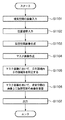
図11は、以上説明した、複合現実空間画像を生成してHMD109に出力する処理のフローチャートである。各ステップにおける処理は上述の通りであるので、ここでは簡単に説明する。
FIG. 11 is a flowchart of the process described above for generating the mixed reality space image and outputting it to the
先ず、ビデオカメラ101により撮像された現実空間の画像がフレーム毎に順次I/F1207を介して本装置内に入力されるので、CPU1201は入力された画像のデータをRAM1202若しくは外部記憶装置1206に格納する(ステップS1101)。
First, since the real space image captured by the
一方、カメラ位置姿勢センサ104が計測したビデオカメラ101の位置姿勢を示すデータがI/F1207を介して本装置内に入力されるので、CPU1201は入力された位置姿勢を示すデータをRAM1202若しくは外部記憶装置1206に格納する(ステップS1102)。
On the other hand, since the data indicating the position and orientation of the
次に、CPU1201は、外部記憶装置1206内に設けられている仮想空間データベース107内に格納されている上記仮想空間データを用いて、仮想空間を構成している各仮想物体を生成して配置し、そしてこのような仮想空間を、ステップS1102で取得した位置姿勢を有する視点から見た場合に見える画像を生成する(ステップS1103)。
Next, the
次に、CPU1201は、上記被写体領域抽出部103として機能し、現実空間画像内において、手205の色と略同じ色を有する領域を示すマスク画像を生成する(ステップS1104)。
Next, the
次に、CPU1201は、生成したマスク画像内で手205の色と同じ色を有する領域として抽出された各領域のうち、手205の領域、手205の領域外を特定する処理を行う(ステップS1105)。より具体的には、例えば、マスク画像において、手205の領域内を構成する各画素の画素値を「1」とし、手205の領域外を構成する各画素の画素値を「0」とする。
Next, the
そして、ステップS1105で生成したマスク画像を用いて、ステップS1101で取得した現実空間の画像上に、ステップS1103で生成した仮想空間の画像を重畳させることで、手205の領域を前景とした複合現実空間画像を生成する(ステップS1106)。
Then, by using the mask image generated in step S1105 and superimposing the virtual space image generated in step S1103 on the real space image acquired in step S1101, the mixed reality with the region of the
そして生成した複合現実空間画像のデータをI/F1207を介してHMD109に対して出力する(ステップS1107)。
The generated mixed reality space image data is output to the
<変形例>
上記閾値決定方法は、体験者の手が視界から消えかかる段階において面積が閾値以下になった途端、視界から消えてしまい、体験者のリアリティを損ねてしまうことがあった。そこで、固定閾値により生じる現象を軽減するために、体験者201および他の体験者208の位置情報を利用し、動的に閾値を決定する。
<Modification>
In the threshold value determination method, as soon as the area of the experiencer's hand disappears from the field of view, the area disappears from the field of view and the reality of the user may be impaired. Therefore, in order to reduce the phenomenon caused by the fixed threshold value, the threshold value is dynamically determined using the positional information of the
まず、カメラ位置姿勢計測部105より体験者201および、他の体験者208の頭部の位置を計測する。そして、計測した位置情報より2者間の距離を算出し、算出した距離に応じて面積の閾値を動的に変更する。閾値は、体験者201の手を伸ばした状態の拳の大きさ(画像上の面積)を最大値とし、最小値はシステムが動作する環境(背景が被写体領域と同様の色情報をどの程度有しているか)に依存してオペレータが決定する。
First, the positions of the heads of the
ここで、閾値の最大値、最小値を求める以上の処理は以下の仮定を前提としている。 Here, the processing beyond obtaining the maximum and minimum threshold values is based on the following assumptions.
即ち、他の体験者208の肌色領域を、体験者201と他の体験者208との位置が十分に離れた状態で、体験者201から見た場合、体験者201の拳の大きさよりも肌色領域の面積は大きくなることはない。つまり、体験者201と他の体験者208との距離が十分に離れている場合は、体験者201の拳の大きさをノイズの閾値(最大値)として、それよりも小さい肌色領域はノイズと見なすことができる。
That is, when the skin color region of another
また、閾値の制御方法に関しては、体験者201とその他の体験者208との距離が近づいた場合には閾値を徐々に増加させる。このとき距離と閾値との関係式に関しては、例えば、距離に係数をかけて線形に閾値を変更させる式や、距離の二乗に比例して閾値を非線形的に変更させる式などが考えられる。
Regarding the threshold control method, the threshold is gradually increased when the distance between the
また、カメラ位置姿勢計測部105の位置情報を利用することによって、体験者の視野内に他の体験者が存在するかどうかを判定し、存在しない場合は特定の面積を持つ領域は体験者の被写体領域であるという仮定を設け、オペレータの設定した閾値を採用するなどしてもよい。
Further, by using the position information of the camera position /
画像情報より閾値以下の面積を持つ被写体領域をノイズと見なすことができるが、閾値以上の面積を持つ被写体領域をノイズ、または体験者の被写体領域かを判断するのは困難である。 A subject area having an area equal to or smaller than the threshold value can be regarded as noise from the image information, but it is difficult to determine whether the subject area having an area equal to or larger than the threshold value is noise or the subject area of the user.
例えば、被写体を体験者の手としているときに、他の体験者の顔が体験者の手よりも大きくビデオカメラ101に映ってしまう場合などである。
For example, when the subject is in the hands of an experienced person, the face of another experienced person appears larger on the
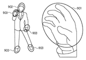
図9は、体験者の視界から他の体験者を見た場合の色情報のみから被写体として判断される領域の分布、および表示領域と非表示領域を説明する図である。図9の右側の手901は体験者自身の手であり、体験者の手は表示したい領域である。そして、図9の左側に表示されている他の体験者の頭部902、および、他の体験者の手や靴903(女性の場合は足の色)などが表示しない領域である。
FIG. 9 is a diagram for explaining the distribution of areas determined as subjects only from color information when other experienced persons are viewed from the field of view of the experienced persons, and display areas and non-display areas. The
ビデオカメラ101で獲得した画像から被写体領域を抽出し、非表示領域を選択除去するためには画像情報のみでは容易に除去することができない。そこで、画像情報に加え、位置姿勢情報も利用する。
In order to extract a subject area from an image acquired by the
カメラ位置姿勢計測部105より他の体験者の頭部の位置姿勢情報を獲得し、他の体験者の頭部を覆うように球、または卵型形状のマスクオブジェクトを3次元空間中に配置する。このとき配置するマスクオブジェクトの形状はシステムの構築環境に応じて好適な任意の形状を選択すると良い。体験者のマスクオブジェクトによって他の体験者の頭部は、被写体領域中のこの領域をマスクキングすることができる。したがって、他の体験者の顔部分に配置したマスクオブジェクトによって、他の体験者の頭部に生じる被写体領域を除去することができる。
The position and orientation information of the head of another experiencer is acquired from the camera position and
本変形例では、他の体験者の頭部のみにマスクオブジェクトを配置したが、他の体験者の手などに位置姿勢センサを取り付けられるシステム環境であれば、他の体験者の手などを覆うような形でマスクオブジェクトを配置する。これにより、他の体験者の手などをロバストに検出し非表示領域にすることができる。 In this modification, the mask object is placed only on the head of another experiencer. However, in a system environment in which the position and orientation sensor can be attached to the hand of another experiencer, the other experiencer's hand is covered. Arrange the mask object like this. This makes it possible to robustly detect the hands of other users and make them non-display areas.
<変形例2>
また、本発明の目的は、前述した実施形態の機能を実現するソフトウェアのプログラムコードを記録した記録媒体(または記憶媒体)を、システムあるいは装置に供給し、そのシステムあるいは装置のコンピュータ(またはCPUやMPU)が記録媒体に格納されたプログラムコードを読み出し実行することによっても、達成されることは言うまでもない。この場合、記録媒体から読み出されたプログラムコード自体が前述した実施形態の機能を実現することになり、そのプログラムコードを記録した記録媒体は本発明を構成することになる。
<
Also, an object of the present invention is to supply a recording medium (or storage medium) in which a program code of software that realizes the functions of the above-described embodiments is recorded to a system or apparatus, and the computer (or CPU or Needless to say, this can also be achieved when the MPU) reads and executes the program code stored in the recording medium. In this case, the program code itself read from the recording medium realizes the functions of the above-described embodiment, and the recording medium on which the program code is recorded constitutes the present invention.
また、コンピュータが読み出したプログラムコードを実行することにより、前述した実施形態の機能が実現されるだけでなく、そのプログラムコードの指示に基づき、コンピュータ上で稼働しているオペレーティングシステム(OS)などが実際の処理の一部または全部を行い、その処理によって前述した実施形態の機能が実現される場合も含まれることは言うまでもない。 Further, by executing the program code read by the computer, not only the functions of the above-described embodiments are realized, but also an operating system (OS) running on the computer based on the instruction of the program code. It goes without saying that a case where the function of the above-described embodiment is realized by performing part or all of the actual processing and the processing is included.
さらに、記録媒体から読み出されたプログラムコードが、コンピュータに挿入された機能拡張カードやコンピュータに接続された機能拡張ユニットに備わるメモリに書込まれた後、そのプログラムコードの指示に基づき、その機能拡張カードや機能拡張ユニットに備わるCPUなどが実際の処理の一部または全部を行い、その処理によって前述した実施形態の機能が実現される場合も含まれることは言うまでもない。 Furthermore, after the program code read from the recording medium is written into a memory provided in a function expansion card inserted into the computer or a function expansion unit connected to the computer, the function is based on the instruction of the program code. It goes without saying that the CPU or the like provided in the expansion card or the function expansion unit performs part or all of the actual processing and the functions of the above-described embodiments are realized by the processing.
本発明を上記記録媒体に適用する場合、その記録媒体には、先に説明したフローチャートに対応するプログラムコードが格納されることになる。 When the present invention is applied to the recording medium, program code corresponding to the flowchart described above is stored in the recording medium.
Claims (6)
前記撮像画像において前記観察者の一部の色として判断する被写体色を登録する登録手段と、
前記取得した撮像画像内で、前記登録された被写体色を有する被写体領域を抽出する抽出手段と、
前記抽出された被写体領域のそれぞれのサイズを求める導出手段と、
前記観察者と前記他の人物との距離を計測する計測手段と、
前記距離に基づいて、前記他の人物によって前記仮想空間の画像がマスクされず、前記観察者の一部によって前記仮想空間の画像がマスクされる被写体領域のサイズの閾値を決定する決定手段と、
前記決定された閾値より大きいサイズの前記抽出された被写体領域を前記観察者の一部とみなして、当該被写体領域により前記仮想空間の画像をマスクするマスク画像を生成する生成手段と、
前記撮像画像に、前記マスク画像でマスクされた前記仮想空間の画像を重畳する重畳手段と、
前記仮想空間の画像を重畳された撮像画像を出力する出力手段と
を有することを特徴とする画像処理装置。 An acquisition means for acquiring a captured image obtained by capturing a part of the observer and the other person from the viewpoint of the observer in a real space where the observer and another person different from the observer exist;
Registration means for registering a subject color to be determined as a partial color of the observer in the captured image;
Extraction means for extracting a subject area having the registered subject color in the acquired captured image;
Derivation means for determining the size of each of the extracted subject areas;
Measuring means for measuring the distance between the observer and the other person ;
Determining means for determining a threshold value of a size of a subject area in which the image of the virtual space is not masked by the other person and the image of the virtual space is masked by a part of the observer based on the distance;
Generating means for considering the extracted subject region having a size larger than the determined threshold as a part of the observer, and generating a mask image for masking the image of the virtual space by the subject region ;
In the captured image, and superimposing means for superimposing the image of the masked the virtual space in the mask image,
An image processing apparatus comprising: output means for outputting a captured image on which an image of the virtual space is superimposed.
前記仮想空間において前記計測された位置にマスクオブジェクトを配する配置手段と
を更に有し、
前記重畳手段が、前記撮像画像における前記マスクオブジェクトが配された領域を仮想画像を重畳してもよい領域として、該撮像画像に仮想空間の画像を重畳することを特徴とする請求項1乃至3の何れか1項に記載の画像処理装置。 Position measuring means for measuring the position of a part of the other person ;
An arrangement means for arranging a mask object at the measured position in the virtual space;
4. The superimposing unit superimposes an image in a virtual space on the captured image, with the region where the mask object is arranged in the captured image being a region on which the virtual image may be superimposed. The image processing apparatus according to any one of the above.
前記画像処理装置が有する取得手段が、観察者と該観察者と異なる他の人物とが存在する現実空間で該観察者の一部と該他の人物とを観察者の視点から撮像した撮像画像を取得する取得工程と、
前記画像処理装置が有する登録手段が、前記撮像画像において前記観察者の一部の色として判断する被写体色を登録する登録工程と、
前記画像処理装置が有する抽出手段が、前記取得した撮像画像内で、前記登録された被写体色を有する被写体領域を抽出する抽出工程と、
前記画像処理装置が有する導出手段が、前記抽出された被写体領域のそれぞれのサイズを求める導出工程と、
前記画像処理装置が有する計測手段が、前記観察者と前記他の人物との距離を計測する計測工程と、
前記画像処理装置が有する決定手段が、前記距離に基づいて、前記他の人物によって前記仮想空間の画像がマスクされず、前記観察者の一部によって前記仮想空間の画像がマスクされる被写体領域のサイズの閾値を決定する決定工程と、
前記画像処理装置が有する生成手段が、前記決定された閾値より大きいサイズの前記抽出された被写体領域を前記観察者の一部とみなして、当該被写体領域により前記仮想空間の画像をマスクするマスク画像を生成する生成工程と、
前記画像処理装置が有する重畳手段が、前記撮像画像に、前記マスク画像でマスクされた前記仮想空間の画像を重畳する重畳工程と、
前記画像処理装置が有する出力手段が、前記仮想空間の画像を重畳された撮像画像を出力する出力工程と
を有することを特徴とする画像処理方法。 An image processing method performed by an image processing apparatus,
The acquired image possessed by the image processing apparatus is a captured image obtained by capturing a part of the observer and the other person from the viewpoint of the observer in a real space where the observer and another person different from the observer exist. An acquisition process for acquiring
A registration step in which a registration unit included in the image processing apparatus registers a subject color to be determined as a partial color of the observer in the captured image;
Extraction means for the image processing apparatus has, in the acquired the captured image, an extraction step of extracting a subject region with the registered subject color,
A deriving step in which a deriving unit included in the image processing apparatus obtains the size of each of the extracted subject areas;
A measuring step that the image processing apparatus has, a measuring step of measuring a distance between the observer and the other person ,
Based on the distance, a determination unit included in the image processing apparatus is configured to determine a subject area in which the virtual space image is not masked by the other person and the virtual space image is masked by a part of the observer . A determining step for determining a size threshold;
A mask image in which the generation unit included in the image processing apparatus regards the extracted subject area having a size larger than the determined threshold as a part of the observer, and masks the image in the virtual space with the subject area. A generating step for generating
Superimposing means for the image processing apparatus has found to the captured image, and superimposing step of superimposing the image of the mask by the mask image the virtual space,
An image processing method comprising: an output unit included in the image processing apparatus that outputs a captured image on which an image of the virtual space is superimposed.
Priority Applications (1)
| Application Number | Priority Date | Filing Date | Title |
|---|---|---|---|
| JP2005168403A JP4745724B2 (en) | 2005-06-08 | 2005-06-08 | Image processing method and image processing apparatus |
Applications Claiming Priority (1)
| Application Number | Priority Date | Filing Date | Title |
|---|---|---|---|
| JP2005168403A JP4745724B2 (en) | 2005-06-08 | 2005-06-08 | Image processing method and image processing apparatus |
Publications (3)
| Publication Number | Publication Date |
|---|---|
| JP2006343953A JP2006343953A (en) | 2006-12-21 |
| JP2006343953A5 JP2006343953A5 (en) | 2010-04-22 |
| JP4745724B2 true JP4745724B2 (en) | 2011-08-10 |
Family
ID=37640888
Family Applications (1)
| Application Number | Title | Priority Date | Filing Date |
|---|---|---|---|
| JP2005168403A Expired - Fee Related JP4745724B2 (en) | 2005-06-08 | 2005-06-08 | Image processing method and image processing apparatus |
Country Status (1)
| Country | Link |
|---|---|
| JP (1) | JP4745724B2 (en) |
Families Citing this family (4)
| Publication number | Priority date | Publication date | Assignee | Title |
|---|---|---|---|---|
| JP5776218B2 (en) * | 2011-02-24 | 2015-09-09 | 株式会社大林組 | Image composition method |
| JPWO2012124250A1 (en) * | 2011-03-15 | 2014-07-17 | パナソニック株式会社 | Object control apparatus, object control method, object control program, and integrated circuit |
| US9418292B2 (en) * | 2011-10-04 | 2016-08-16 | Here Global B.V. | Methods, apparatuses, and computer program products for restricting overlay of an augmentation |
| EP2863382A4 (en) * | 2012-06-18 | 2016-02-24 | Sony Corp | Image display device, image display program, and image display method |
Citations (2)
| Publication number | Priority date | Publication date | Assignee | Title |
|---|---|---|---|---|
| JP2001016606A (en) * | 1999-06-29 | 2001-01-19 | Sharp Corp | Operation recognition system and recording medium recording operation recognition program |
| JP2005107967A (en) * | 2003-09-30 | 2005-04-21 | Canon Inc | Image composition apparatus and method |
Family Cites Families (3)
| Publication number | Priority date | Publication date | Assignee | Title |
|---|---|---|---|---|
| JP4597391B2 (en) * | 2001-01-22 | 2010-12-15 | 本田技研工業株式会社 | Facial region detection apparatus and method, and computer-readable recording medium |
| US20030161506A1 (en) * | 2002-02-25 | 2003-08-28 | Eastman Kodak Company | Face detection computer program product for redeye correction |
| JP4126721B2 (en) * | 2002-12-06 | 2008-07-30 | 富士フイルム株式会社 | Face area extraction method and apparatus |
-
2005
- 2005-06-08 JP JP2005168403A patent/JP4745724B2/en not_active Expired - Fee Related
Patent Citations (2)
| Publication number | Priority date | Publication date | Assignee | Title |
|---|---|---|---|---|
| JP2001016606A (en) * | 1999-06-29 | 2001-01-19 | Sharp Corp | Operation recognition system and recording medium recording operation recognition program |
| JP2005107967A (en) * | 2003-09-30 | 2005-04-21 | Canon Inc | Image composition apparatus and method |
Also Published As
| Publication number | Publication date |
|---|---|
| JP2006343953A (en) | 2006-12-21 |
Similar Documents
| Publication | Publication Date | Title |
|---|---|---|
| JP4136420B2 (en) | Information processing method and apparatus | |
| US10701332B2 (en) | Image processing apparatus, image processing method, image processing system, and storage medium | |
| JP5818773B2 (en) | Image processing apparatus, image processing method, and program | |
| JP5474169B2 (en) | Image processing apparatus and image processing method | |
| US10339712B2 (en) | Image processing apparatus and image processing method | |
| US8280115B2 (en) | Image processing apparatus and image processing method | |
| US7519218B2 (en) | Marker detection method and apparatus, and position and orientation estimation method | |
| US9679415B2 (en) | Image synthesis method and image synthesis apparatus | |
| US8860847B2 (en) | Computer-readable storage medium having stored thereon image generation program, capturing apparatus, capturing system, and image generation method for creating an image | |
| US8184907B2 (en) | Image processing method and image processing apparatus | |
| JP4745724B2 (en) | Image processing method and image processing apparatus | |
| CN114241168A (en) | Display method, display device, and computer-readable storage medium | |
| JP2008146108A (en) | Index, image processor and image processing method | |
| US11275434B2 (en) | Information processing apparatus, information processing method, and storage medium | |
| JP4323910B2 (en) | Image composition apparatus and method | |
| JP2022524787A (en) | Methods, systems, and programs for object detection range estimation | |
| JP6858007B2 (en) | Image processing system, image processing method | |
| JP4217661B2 (en) | Image processing method and image processing apparatus | |
| JP2008299670A (en) | Image area extraction device and its control method, composite reality presentation system and computer program | |
| JP2009015648A (en) | Image processor and image processing method | |
| JP7005134B2 (en) | Image processing equipment, image processing methods and programs | |
| JP7175715B2 (en) | Information processing device, information processing method and program | |
| JP6700804B2 (en) | Information processing apparatus, information processing method, and program | |
| CN116797643A (en) | Method for acquiring user fixation area in VR, storage medium and electronic device | |
| JP2019079299A (en) | Information processing device, information processing method, and program |
Legal Events
| Date | Code | Title | Description |
|---|---|---|---|
| A621 | Written request for application examination |
Free format text: JAPANESE INTERMEDIATE CODE: A621 Effective date: 20080609 |
|
| A521 | Request for written amendment filed |
Free format text: JAPANESE INTERMEDIATE CODE: A523 Effective date: 20100308 |
|
| A977 | Report on retrieval |
Free format text: JAPANESE INTERMEDIATE CODE: A971007 Effective date: 20100928 |
|
| A131 | Notification of reasons for refusal |
Free format text: JAPANESE INTERMEDIATE CODE: A131 Effective date: 20101001 |
|
| A521 | Request for written amendment filed |
Free format text: JAPANESE INTERMEDIATE CODE: A523 Effective date: 20101130 |
|
| A02 | Decision of refusal |
Free format text: JAPANESE INTERMEDIATE CODE: A02 Effective date: 20110107 |
|
| A521 | Request for written amendment filed |
Free format text: JAPANESE INTERMEDIATE CODE: A523 Effective date: 20110407 |
|
| A911 | Transfer to examiner for re-examination before appeal (zenchi) |
Free format text: JAPANESE INTERMEDIATE CODE: A911 Effective date: 20110418 |
|
| TRDD | Decision of grant or rejection written | ||
| A01 | Written decision to grant a patent or to grant a registration (utility model) |
Free format text: JAPANESE INTERMEDIATE CODE: A01 Effective date: 20110509 |
|
| A01 | Written decision to grant a patent or to grant a registration (utility model) |
Free format text: JAPANESE INTERMEDIATE CODE: A01 |
|
| A61 | First payment of annual fees (during grant procedure) |
Free format text: JAPANESE INTERMEDIATE CODE: A61 Effective date: 20110512 |
|
| FPAY | Renewal fee payment (event date is renewal date of database) |
Free format text: PAYMENT UNTIL: 20140520 Year of fee payment: 3 |
|
| R150 | Certificate of patent or registration of utility model |
Ref document number: 4745724 Country of ref document: JP Free format text: JAPANESE INTERMEDIATE CODE: R150 Free format text: JAPANESE INTERMEDIATE CODE: R150 |
|
| LAPS | Cancellation because of no payment of annual fees |