JP5818773B2 - Image processing apparatus, image processing method, and program - Google Patents
Image processing apparatus, image processing method, and program Download PDFInfo
- Publication number
- JP5818773B2 JP5818773B2 JP2012256463A JP2012256463A JP5818773B2 JP 5818773 B2 JP5818773 B2 JP 5818773B2 JP 2012256463 A JP2012256463 A JP 2012256463A JP 2012256463 A JP2012256463 A JP 2012256463A JP 5818773 B2 JP5818773 B2 JP 5818773B2
- Authority
- JP
- Japan
- Prior art keywords
- image
- distance
- reliability
- distance data
- region
- Prior art date
- Legal status (The legal status is an assumption and is not a legal conclusion. Google has not performed a legal analysis and makes no representation as to the accuracy of the status listed.)
- Active
Links
Images


Classifications
-
- G—PHYSICS
- G01—MEASURING; TESTING
- G01C—MEASURING DISTANCES, LEVELS OR BEARINGS; SURVEYING; NAVIGATION; GYROSCOPIC INSTRUMENTS; PHOTOGRAMMETRY OR VIDEOGRAMMETRY
- G01C3/00—Measuring distances in line of sight; Optical rangefinders
- G01C3/02—Details
- G01C3/06—Use of electric means to obtain final indication
- G01C3/08—Use of electric radiation detectors
-
- G—PHYSICS
- G06—COMPUTING; CALCULATING OR COUNTING
- G06T—IMAGE DATA PROCESSING OR GENERATION, IN GENERAL
- G06T7/00—Image analysis
- G06T7/50—Depth or shape recovery
- G06T7/55—Depth or shape recovery from multiple images
- G06T7/593—Depth or shape recovery from multiple images from stereo images
-
- G—PHYSICS
- G06—COMPUTING; CALCULATING OR COUNTING
- G06T—IMAGE DATA PROCESSING OR GENERATION, IN GENERAL
- G06T7/00—Image analysis
- G06T7/80—Analysis of captured images to determine intrinsic or extrinsic camera parameters, i.e. camera calibration
- G06T7/85—Stereo camera calibration
-
- G—PHYSICS
- G06—COMPUTING; CALCULATING OR COUNTING
- G06T—IMAGE DATA PROCESSING OR GENERATION, IN GENERAL
- G06T2207/00—Indexing scheme for image analysis or image enhancement
- G06T2207/10—Image acquisition modality
- G06T2207/10016—Video; Image sequence
- G06T2207/10021—Stereoscopic video; Stereoscopic image sequence
-
- G—PHYSICS
- G06—COMPUTING; CALCULATING OR COUNTING
- G06T—IMAGE DATA PROCESSING OR GENERATION, IN GENERAL
- G06T2207/00—Indexing scheme for image analysis or image enhancement
- G06T2207/20—Special algorithmic details
- G06T2207/20076—Probabilistic image processing
Description
本発明は、特に、物体との距離を測定して表示画像を生成するために用いて好適な画像処理装置、画像処理方法、及びプログラムに関する。 The present invention is particularly suitable image processing apparatus, image processing method used to generate the display image by measuring the distance to the object, and relates to a program.
従来、赤外線のような光線を物体に反射させ、光線が反射して戻ってくる時間を計測することによって、対象物体と装置との距離を計測するTOF(Time of Flight)方式の距離計測方式が知られている。この距離計測方式を採用したセンサとして、TOF方式の距離センサがある。 Conventionally, TOF (Time of Flight) distance measurement method that measures the distance between a target object and a device by reflecting light rays such as infrared rays on an object and measuring the time when the light rays are reflected back. Are known. As a sensor that employs this distance measuring method, there is a TOF type distance sensor.
このTOF方式の距離センサは、照射した光と反射して戻ってきた光との位相差を検出して対象物までの距離を測定する。例えば、特許文献1に記載されているように、照射した光の強度を1周期に対して4回計測することにより検出された発光信号と放射された変調信号との間の位相差を求めて距離を測定する。また、距離センサによっては、2次元に配列されたセンサアレイで前述の距離計測を同時に処理するため、距離データを逐次12Hz〜29Hzの速度で176×144の解像度の距離画像として出力することができる。 This TOF type distance sensor detects the phase difference between the irradiated light and the reflected light, and measures the distance to the object. For example, as described in Patent Document 1, the phase difference between the detected emission signal and the emitted modulation signal is obtained by measuring the intensity of the irradiated light four times for one period. Measure distance. Further, depending on the distance sensor, since the above-described distance measurement is simultaneously processed by a two-dimensionally arranged sensor array, the distance data can be sequentially output as a distance image having a resolution of 176 × 144 at a speed of 12 Hz to 29 Hz. .
しかし、TOF方式の距離センサは、対象物体が静止していることを前提に設計されているため、対象物体が動く場合には、対象物体の距離計測値に大きな誤差が生じる。すなわち、距離センサが、距離を計測する1つの過程において異なるタイミングでサンプリングして最終的な距離を決定しているため、対象物体が高速で移動すると、検出された発光信号が変形し、放射された変調信号との位相差を正しく求めることができない。 However, since the TOF type distance sensor is designed on the assumption that the target object is stationary, a large error occurs in the distance measurement value of the target object when the target object moves. That is, since the distance sensor determines the final distance by sampling at different timings in one process of measuring the distance, when the target object moves at high speed, the detected light emission signal is deformed and emitted. The phase difference from the modulated signal cannot be obtained correctly.
ここで、図9に示す人の手402Lまでの距離を距離計測装置で計測している状況を例に説明する。図10は、距離計測装置と手402Lとが静止している状態で手402Lまでの距離を計測し、出力された距離データから生成される3次元ポリゴンメッシュ1010の表示結果を示す模式図である。このように計測対象が静止している状態であれば、比較的精度を高く距離を計測することができる。しかし、対象物体の手402Lが移動を始めると、輪郭部分に大きな計測誤差が発生する。
Here, a situation where the distance to the
図11は、手402Lが左方向に移動している状態で手402Lまでの距離を計測した場合の3次元ポリゴンメッシュ1010の表示結果を示す模式図である。また、図12は、図11に示す手402Lの断面1110を横から見た模式図である。図11及び図12で示すように、進行方向の輪郭の距離計測値は距離計測装置の手前側に計測誤差が大きくなり、進行方向の逆の輪郭領域では、距離計測装置の奥側に計測誤差が大きくなる。輪郭部で誤差が拡大するのは、距離計測の1過程において異なる時間で複数回サンプリングするときに、移動する対象物体の輪郭部分の信号が、対象物体から反射した正しい信号と対象物体以外の場所から反射した誤りの信号とを統合して生成されるからである。すなわち、照射した光の信号と受光した信号との位相差を計測するときに、誤った受光信号で比較するために距離計測の誤差が拡大する。また、同様の理由で、装置自身が動く場合も正しく位相差を求められないため、装置自身を人体に取り付けて移動させるような場面では、装置が動くたびに大きな計測誤差が発生する。
FIG. 11 is a schematic diagram illustrating a display result of the three-
さらに、別の課題として、光線を反射して距離を計測するTOF方式の距離計測装置では、発光した光線が戻ってくる量で距離を測定するため、光線を吸収するような素材や、反射率の高い素材の物体の距離を計測すると距離精度は著しく低下する。特に、表面の色が黒っぽい物体では光線を吸収しやすい。また、表面の粒度が細かく光線を多く反射する場合は、スペキュラ成分としてカメラ画像で最高輝度の白い領域となる場合が多い。 Furthermore, as another problem, in the distance measuring device of the TOF method that measures the distance by reflecting the light, the distance is measured by the amount of the emitted light that returns, so the material that absorbs the light and the reflectance When measuring the distance of objects of high material, the distance accuracy is significantly reduced. In particular, an object having a black surface color is likely to absorb light. In addition, when the surface has a fine particle size and many light rays are reflected, the specular component often becomes a white region having the highest luminance in the camera image.
本発明は前述の問題点に鑑み、計測対象の物体または装置自身が動く場合に、距離計測値の誤差を低減できるようにすることを目的としている。 In view of the above-described problems, an object of the present invention is to reduce an error in a distance measurement value when an object to be measured or the apparatus itself moves.
本発明の画像処理装置は、物体までの距離を計測し、第1の距離データとして生成する距離計測手段と、前記物体を含む撮像画像を取得する画像取得手段と、前記距離計測手段の移動速度および移動方向を取得する取得手段と、前記撮像画像から前記物体の輪郭領域を抽出する抽出手段と、前記取得手段によって取得された前記距離計測手段の移動速度および移動方向に基づいて、前記抽出された輪郭領域を拡大する拡大手段と、前記拡大手段によって拡大された輪郭領域に基づいて、前記第1の距離データにおける計測値の信頼度を算出する信頼度算出手段と、前記信頼度算出手段によって算出された信頼度に基づいて前記第1の距離データの計測値から信頼度の高い領域を抽出し、前記第1の距離データよりも信頼度の高い第2の距離データを生成する第1の補正手段と、を備えることを特徴とする。 The image processing apparatus of the present invention measures a distance to an object, generates distance measurement means as first distance data, image acquisition means for acquiring a captured image including the object, and movement speed of the distance measurement means And the acquisition means for acquiring the moving direction, the extracting means for extracting the contour region of the object from the captured image, and the extraction based on the moving speed and moving direction of the distance measuring means acquired by the acquiring means. and enlarging means for enlarging the outline area, based on the enlarged contour regions by said expansion means, a reliability calculation means calculates the reliability of the measurement value of the first distance data, by the reliability calculation means A region having high reliability is extracted from the measurement value of the first distance data based on the calculated reliability, and a second distance data having higher reliability than the first distance data is extracted. Characterized by comprising a first correction means for generating a data, a.
本発明によれば、計測対象の物体または装置自身が動く場合に、距離計測値の誤差を低減することができる。 According to the present invention, it is possible to reduce errors in distance measurement values when an object to be measured or the apparatus itself moves.
(第1の実施形態)
以下、添付図面を参照して、本発明の最適な実施形態について詳細に説明する。以下の説明においては、ビデオシースルー(Video See-Through)型のヘッドマウントディスプレイ(HMD)を用いた複合現実感(Mixed Reality:MR)提示システムに本発明の画像処理装置を適用した場合について説明する。
(First embodiment)
DESCRIPTION OF EXEMPLARY EMBODIMENTS Hereinafter, exemplary embodiments of the invention will be described in detail with reference to the accompanying drawings. In the following description, a case where the image processing apparatus of the present invention is applied to a mixed reality (MR) presentation system using a video see-through type head mounted display (HMD) will be described. .
MR提示システムでは、現実空間の画像とコンピュータグラフィックス等の仮想空間の画像とを合成した合成画像を、ユーザ(MR体験者)に提示することができる。この合成画像を提示することにより、CADモデルなどの現実にはない物体が、あたかもその場にあるかのようにユーザに提示することができるようになる。なお、MR技術の詳細については、例えば、非特許文献1に開示されている。 In the MR presentation system, a synthesized image obtained by synthesizing a real space image and a virtual space image such as computer graphics can be presented to a user (MR experience person). By presenting this composite image, an object that does not exist in reality, such as a CAD model, can be presented to the user as if it were there. Details of the MR technique are disclosed in Non-Patent Document 1, for example.
<MRを実現するための現実空間と仮想物体との位置合わせについて>
MR空間を表現するためには、現実空間中に定義した基準座標系(重畳しようとする仮想物体の位置姿勢を決定する基準となる現実空間中の座標系)とカメラ座標系との間の、相対的な位置姿勢を推定することが不可欠である。これは、仮想物体を現実空間上の位置に合わせて描画するには、基準座標系に対するカメラの実際のカメラパラメータと同一のカメラパラメータで仮想物体の画像を生成しなければならないからである。
<Registration between real space and virtual object to realize MR>
In order to express the MR space, a reference coordinate system defined in the real space (a coordinate system in the real space that serves as a reference for determining the position and orientation of the virtual object to be superimposed) and the camera coordinate system, It is essential to estimate the relative position and orientation. This is because in order to draw a virtual object in accordance with the position in the real space, an image of the virtual object must be generated with the same camera parameters as the actual camera parameters of the camera with respect to the reference coordinate system.
ここで、カメラパラメータとは、焦点距離や主点などのカメラ内部パラメータと、カメラの位置及び姿勢を表すカメラ外部パラメータとを指す。本実施形態では、焦点距離が不変となるカメラを利用するため、カメラ内部パラメータは固定値となり、予め用意しておくことが可能である。 Here, the camera parameters refer to camera internal parameters such as focal length and principal point, and camera external parameters representing the position and orientation of the camera. In this embodiment, since a camera whose focal length does not change is used, the camera internal parameter is a fixed value and can be prepared in advance.
例えば、現実のテーブル上のある位置に仮想物体を重畳表示する場合には、テーブルに基準座標系を定義し、その基準座標系におけるカメラの位置姿勢を求めればよい。なお、以下では、基準座標系とカメラとの間の相対的な位置姿勢を、便宜的に「カメラ位置姿勢」と呼称する。基準座標系とカメラとの間の相対的な位置姿勢とは、一意に変換可能でありかつ本質的に同一の事象を表す情報を総称するものである。例えば、基準座標系に対するカメラ位置姿勢、カメラに対する基準座標系の位置姿勢、あるいは、これらを表現可能なデータ形式(例えば、基準座標系からカメラ座標系への座標変換行列や、カメラ座標系から基準座標系への座標変換行列)といったものである。 For example, when a virtual object is superimposed and displayed at a certain position on an actual table, a reference coordinate system is defined in the table, and the position and orientation of the camera in the reference coordinate system may be obtained. Hereinafter, the relative position and orientation between the reference coordinate system and the camera are referred to as “camera position and orientation” for convenience. The relative position / orientation between the reference coordinate system and the camera is a generic term for information that can be uniquely converted and that represents essentially the same event. For example, the camera position and orientation with respect to the reference coordinate system, the position and orientation of the reference coordinate system with respect to the camera, or a data format that can express these (for example, a coordinate transformation matrix from the reference coordinate system to the camera coordinate system, or a reference from the camera coordinate system Coordinate conversion matrix to coordinate system).
<MR空間で手を表示する従来技術1:単純な上書き合成>
ビデオシースルー型のHMDでMRを体験する場合に、カメラで得られたカメラ画像を背景として仮想物体をその上に合成表示することが一般的に実施されている。
<Conventional technology for displaying hands in MR space 1: simple overwrite synthesis>
When experiencing MR with a video see-through type HMD, it is a common practice to synthesize and display a virtual object on a background of a camera image obtained by a camera.
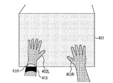
以下、図4に示すように、MR体験者403がHMD100を頭部に装着し、直方体の3次元モデルである仮想物体401があたかも現実空間にあるかのように提示されている状態の例について説明する。ただし、図4においては、MR体験者403の手402L、402Rが仮想物体401に接触しているものとする。また、図5は、MR体験者403がHMD100に内蔵されているディスプレイから提示されている画像を示す模式図である。図5においては、仮想物体401が、カメラ画像として撮影された自分の手402L、402Rよりも手前に表示されることを示している。MR体験者403自身は、仮想物体401と自分の手402L、402Rとの距離感覚を掴んでいるのに、図5に示すように自分の距離感覚とは違う映像を提示されると違和感を生じる場合がある。
Hereinafter, as shown in FIG. 4, an
<MR空間で手を表示する従来技術2:色領域抽出による仮想物体非表示>
この違和感を軽減するために、肌色領域を画像中から抽出し、肌色領域には仮想物体401の画像を上書きしないで表示することが、例えば特許文献2に開示されている。図6には、肌色領域に仮想物体401の画像を描画しない場合の模式図を示す。
<Conventional technique 2 for displaying hand in MR space: Virtual object non-display by color area extraction>
In order to reduce this uncomfortable feeling, for example, Patent Document 2 discloses that a skin color region is extracted from an image and displayed without overwriting the image of the
<MR空間で手を表示する従来技術3:距離データを用いた領域抽出と仮想物体非表示>
しかし、図6に示す手402Lには、リストバンド410があり、リストバンド410の領域610は肌色ではないため、仮想物体401の画像が描画されてしまう。そこで、非特許文献2に記載の技術では、背景との画像差分で得た領域の輪郭線を、ステレオ法により距離計測し、前後判定(Zバッファによる比較)を行うことにより奥行きを考慮した描画を可能にしている。非特許文献2に記載の手法では、色ではなく、背景との画像差分によって仮想物体401の画像を表示しない領域を決定するため、リストバンド410の部分に仮想物体401の画像は表示されず、体験者の違和感を軽減する。また、非特許文献2に記載の手法では、輪郭線のカメラとの距離を求めることにより仮想物体401との接触領域を推定することができるため、図7に示すような違和感の少ない映像を生成することができる。
<Prior Art 3 for Displaying Hands in MR Space: Extraction of Region Using Distance Data and Non-Display of Virtual Object>
However, the
<TOF方式の画像処理装置をMRシステムに用いる場合の課題>
しかし、前述したように、従来のTOF方式の距離計測装置では、対象物体との相対位置が変わると計測精度が落ちる場合がある。特に、図4に示すように、頭部に距離計測部150を取り付ける場合は、計測方向の対象物体との相対位置のずれが大きくなる。図11で示すように手402Lと距離計測結果から得た3次元ポリゴンメッシュ1010の誤差が大きいと、図7に示したような映像は得られず、図8に示すように仮想物体401の画像も一部810が欠けた映像が生成される。
<Problems in using TOF type image processing apparatus in MR system>
However, as described above, in the conventional TOF type distance measuring device, the measurement accuracy may decrease if the relative position with the target object changes. In particular, as shown in FIG. 4, when the
本実施形態のでは、図4で示すように距離計測部150と計測対象との相対位置が動的に変化する場合に発生する距離計測値の誤差を低減する。そして、図8に示すような距離計測の誤差による没入感の阻害を軽減するMR提示システムについて説明する。
In the present embodiment, as shown in FIG. 4, the error of the distance measurement value that occurs when the relative position between the
図14は、本実施形態における、距離計測値の補正の流れに沿った処理画像を示す模式図である。以下に、この処理の流れの概略を示す。
まず、本実施形態では、カメラ101で撮影されたカメラ画像1401から、カメラ画像1401の夫々の画素における距離計測値の信頼度を示す信頼度画像1305を生成する。
FIG. 14 is a schematic diagram showing a processed image along the flow of distance measurement value correction in the present embodiment. The outline of this processing flow is shown below.
First, in the present embodiment, a
次に、信頼度画像1305に、距離データを画像に表現した距離画像1405の距離計測値をマッピングし、高信頼度距離画像1410を生成する。ただし、単純にマッピングするのではなく、対応する画素の信頼度に応じてマッピングすることにより、対象物体が動いている場合の誤差を排除しながら距離計測値をマッピングする。なお、距離画像1405は、距離計測部150において第1の距離データとして距離測定値を画像に表現したものである。
Next, the distance measurement value of the
さらに、高信頼度距離画像1410において、本来のカメラ画像1401の対象物体の領域に対して欠けている領域を、カメラ画像1401から抽出した輪郭線まで補間及び補外し、最終的な補正距離画像1420を生成する。以上のような流れによりカメラ画像1401と距離画像1405とを利用して、動いている対象物体の距離計測誤差を補正する。なお、信頼度画像1305、高信頼度距離画像1410、及び補正距離画像1420の生成方法の詳細については後述する。
Further, in the high-
<構成>
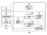
図1は、本実施形態に係る画像処理装置を含むMR提示システムの機能構成例を示すブロック図である。本実施形態においては、MR体験者403に、仮想物体401をあたかもその場にあるように体験させることを目的とする。仮想物体401の存在感を出すためには、図7に示すように、MR体験者403が感じる自分の手402L、402Rと仮想物体401との距離感覚と、提示される映像とが近いことが望ましい。
<Configuration>
FIG. 1 is a block diagram illustrating a functional configuration example of an MR presentation system including an image processing apparatus according to the present embodiment. The purpose of this embodiment is to allow the
図1において、HMD100には、カメラ101、表示部103及び距離計測部150が取り付けられており、これらはHMD100に固定されている。距離計測部150は、光線を物体に反射させ、光線が反射して戻ってくる時間を計測することによって対象物体と装置との距離を計測するTOF方式のものである。本実施形態では、図2に示すように、カメラ101及び表示部103は右目用及び左目用として2つずつHMD100の本体内に設けられており、カメラ101R及び表示部103Rは右目用であり、カメラ101L及び表示部103Lは左目用である。これにより、このHMD100を頭部に装着したMR体験者403の右目及び左目には、それぞれ独立した画像を提示することができ、ステレオでもって画像を提示することができる。
In FIG. 1, a
本実施形態では、カメラ101Rが撮影した現実空間の撮像画像と、ワークステーション160が生成した右目用の仮想空間の画像とが重畳された画像(以下、MR画像と呼称する)を表示部103Rにより右目に提示する。さらに、カメラ101Lが撮影した現実空間の撮像画像と、ワークステーション160が生成した左目用の仮想空間の画像とが重畳されたMR画像を表示部103Lにより左目に提示する。その結果、MR体験者403はMR画像をステレオで観察することができる。なお、以下に説明する処理の本質はステレオ画像でMR画像をMR体験者403に提示することに限定されるものではない。すなわち、1つのカメラ及び表示部を両目で共有してモノラル画像を観察する場合や、単眼のみに表示する場合であってもよい。
In the present embodiment, an image (hereinafter referred to as an MR image) obtained by superimposing a captured image of the real space captured by the
また、MR体験者403にMR画像を提示するための手段として本実施形態ではHMD100を用いるが、以下に説明する処理の本質はこの装置に限定されるものではなく、カメラ101と表示部103とを少なくとも1対有する装置であればよい。さらには、カメラ101及び表示部103は互いに固定されている必要もない。ただし、カメラ101及び距離計測部150は、同一の環境を計測するように近づけて固定する必要がある。
In addition, the
次に、図1に示すワークステーション160について説明する。
記憶部109は、画像取得手段であるカメラ101で撮影されたカメラ画像と、距離計測部150により生成された前述の距離画像とを記憶する。また、記憶部109は、本実施形態におけるMR提示システムの処理に必要な情報を保持しており、処理に応じて情報の読み出しや更新を行う。MR提示システムの処理に必要な情報とは、例えば、カメラ画像、前フレームのカメラ画像、距離画像、カメラ101の位置姿勢の情報、及び距離計測部150の位置姿勢の履歴情報がある。さらには、予め校正したカメラ画像及び距離画像のホモグラフィ変換行列、焦点距離や、主点位置、レンズ歪み補正パラメータなどのカメラ内部パラメータ、マーカ定義情報、及びカメラ画像の輪郭情報がある。さらに、距離計測部150の速度の情報、距離計測部150の移動方向の情報、前述した信頼度画像、高信頼度距離画像、補正距離画像、仮想物体401のモデル情報などの情報がある。なお、本実施形態では、これらの項目を利用することに限定されるものではなく、処理する内容に応じて増減させてもよい。
Next, the
The
また、記憶部109は、複数のカメラ画像を保持する領域を備えており、動画のフレームとして各々のカメラ画像を格納する。
The
カメラ位置姿勢推定部108は、記憶部109に格納されたカメラ画像からカメラ101及び距離計測部150の位置姿勢を求める。本実施形態では、例えば、図9に示すように、カメラ101が撮影したカメラ画像1401に映る矩形のマーカ400A、400Bをカメラ画像1401から検出し、矩形の4頂点の座標を利用してカメラ101の位置姿勢を求める。矩形のマーカ400A、400Bから相対的なカメラ101の位置姿勢を求める方法は、例えば非特許文献3に記載されているカメラ位置姿勢推定方法を利用すればよい。すなわち、画像内におけるマーカの矩形領域の4頂点とカメラ座標の原点とを結んでできる四角錘のうち、側面の4つの法線で隣りあう法線の外積方向を用いて基準座標系におけるマーカの3次元姿勢を算出する。さらに、3次元姿勢から幾何計算により3次元位置も求められる。これらの結果からカメラ101の位置姿勢を行列として保持する。
The camera position /
なお、カメラの位置姿勢を求めるのに、矩形のマーカを用いることに限定されるものではなく、磁気センサや光学センサなど、動いている頭部の位置姿勢を計測できる方法であれば適用可能である。 Note that the camera position and orientation are not limited to using rectangular markers, and any method that can measure the position and orientation of a moving head, such as a magnetic sensor or an optical sensor, can be applied. is there.
次に、予め計測して記憶部109に格納されているカメラ101と距離計測部150との相対位置姿勢を表す行列に、この行列をかけることによって距離計測部150の位置姿勢の情報を得る。そして、ここで得られたカメラ101の位置姿勢及び距離計測部150の位置姿勢の情報は記憶部109に格納される。ただし、距離計測部150の位置姿勢の情報は、位置姿勢を記録した時間とともに、距離計測部150の位置姿勢の履歴として格納される。また、記憶部109にこれらの情報が格納されると、直前の距離計測部150の位置姿勢と現在の距離計測部150の位置姿勢との差分から移動速度及び移動方向を算出することができ、記憶部109に格納される。このようにカメラ位置姿勢推定部108は、速度検出手段及び移動方向検出手段として機能する。
Next, information on the position and orientation of the
信頼度算出部105は、記憶部109に格納されたカメラ画像と距離計測部150の位置姿勢の履歴情報とに基づいて、距離計測部150が計測した距離計測値の信頼度を表す信頼度画像を生成する。信頼度は、0から255の間の整数値で決定され、信頼度の値が高い方が、距離計測値としての信頼度が高いとみなす。信頼度算出部105では、カメラ画像の各画素における信頼度を1画素ずつ決定し、最終的には図14に示すような信頼度を輝度値とするグレイスケールの画像として信頼度画像を記憶部109に格納する。
The
距離データ補正部106は、まず、記憶部109に格納された信頼度画像の画素に、距離計測部150の距離画像の距離計測値を対応付ける。この対応付け処理では、距離画像と信頼度画像とで解像度が異なる場合は、例えば、非特許文献4に記載されている方法を用いて、距離画像を超解像度化した結果の距離画像を対応付ければよい。すなわち、距離画像を超解像化する場合に、単純に補間するのではなく、カメラ画像の対応画素における色や輝度の差分値に基づいて補間する。
First, the distance
次に、信頼度画像に格納されている信頼度に応じて対応付けた距離計測値を取捨選択する。本実施形態では、例えば、予め信頼度に閾値を設定し、閾値を超える信頼度に対応する距離計測値のみを残し、残りの距離計測値は使用しないように設定する。このように選択した距離計測値は、カメラ画像の各画素に対応する高信頼度距離画像として記憶部109に格納される。なお、このように信頼度に閾値を設定して距離計測値を除去することに限定されるものではない。例えば、信頼度画像において信頼度のヒストグラムを生成し、信頼度が128以上でヒストグラムの頻度が高い上位10個の信頼度に対応する距離計測値のみを選択してもよい。
Next, a distance measurement value associated with the reliability stored in the reliability image is selected. In the present embodiment, for example, a threshold value is set in advance for reliability, and only the distance measurement value corresponding to the reliability exceeding the threshold value is left, and the remaining distance measurement value is set not to be used. The distance measurement value thus selected is stored in the
次に、図14に示す概要によって信頼度から選択して更新された高信頼度距離画像は、除去された部分の距離計測値が欠落しているため、内挿補間及び外挿補外によりカメラ画像から得た輪郭線の部分まで欠落領域を埋める。そして、欠落領域を埋めた画像を補正距離画像として記憶部109に格納する。
Next, since the high reliability distance image selected and updated from the reliability according to the outline shown in FIG. 14 is missing the distance measurement value of the removed part, the camera is obtained by interpolation and extrapolation. The missing area is filled up to the contour line obtained from the image. Then, the image in which the missing area is filled is stored in the
仮想画像生成部110は、カメラ位置姿勢推定部108から出力されるカメラ101の位置姿勢の情報に基づいて、この視点の位置姿勢から見える仮想物体の画像を生成(描画)する。ただし、仮想物体の画像を生成するときに、現在描画する場所のZバッファ値と、距離データ補正部106で生成された補正距離画像に対応する画素における距離計測値とを比較する。具体的には、Zバッファ値が距離計測値よりも大きい場合のみ仮想物体の画像を描画する。このように処理することによって、画像合成部111でカメラ画像と合成するときに、図7に示すように、仮想物体401よりも手前にある現実の対象物体の手402L、402Rが仮想物体401の画像に上書きされずに体験者に提示することができる。
The virtual
画像合成部111は、記憶部109が保持しているカメラ画像と、仮想画像生成部110によって生成された仮想物体の画像(仮想空間の画像)とを合成した画像(MR画像)を生成する。この合成については、カメラ画像上に仮想空間の画像を重畳することにより行われる。そして、画像合成部111は、MR画像をHMD100の表示部103に出力する。これにより、表示部103には、カメラ101の位置姿勢に応じた現実空間の画像と仮想空間の画像とが重畳されたMR画像が表示され、このHMD100を頭部に装着したMR体験者に、このMR画像を提示することができる。
The
なお、図1において、HMD100に取り付けられているハードウェアを除くすべての機能は、ワークステーション160の機能構成に含まれるものとする。このワークステーション160の基本的なハードウェア構成としては、CPU、RAM、ROM、外部記憶装置、記憶媒体ドライブ装置、キーボード、及びマウスを備えている。CPUはRAMやROMに格納されているプログラムやデータを用いて、ワークステーション160全体の制御を行うとともに、MR画像を生成し、HMD100の表示部103に出力するまでの一連の処理を実行する。
In FIG. 1, all functions except hardware attached to the
RAMは、外部記憶装置や記憶媒体ドライブ装置から読み出されたプログラムやデータを一時的に記憶するためのエリアを備えるとともに、CPUが各種の処理を実行するために用いるワークエリアも備える。ROMは、ブートプログラムなど、ワークステーション160全体の制御を行うためのプログラムやデータ等を格納する。キーボード、マウスは、各種の指示をCPUに入力することができる。ハードディスクドライブ装置等に代表される大容量情報記憶装置は、OS(オペレーティングシステム)や、CPUが上記MR画像を生成して表示部103に出力するまでの一連の処理を実行するために必要なプログラムやデータを格納する。格納されるプログラムやデータはRAMに読み出され、CPUの実行対象となる。
The RAM includes an area for temporarily storing programs and data read from the external storage device and the storage medium drive device, and also includes a work area used by the CPU to execute various processes. The ROM stores programs, data, and the like for controlling the
なお、図1に示した信頼度算出部105、距離データ補正部106、カメラ位置姿勢推定部108、仮想画像生成部110、及び画像合成部111はプログラムにより実装してもよい。その場合、このプログラムを外部記憶装置に保存しておき、必要に応じてRAMに読み出し、CPUがこのプログラムに従って処理を実行する。これにより、ワークステーション160は、以上に説明したMR画像を生成して表示部103に出力するまでの一連の処理を実行することができる。
The
<処理の手順>
次に、本実施形態における処理の手順について、図3のフローチャートを参照しながら説明する。なお、図3に示すフローチャートの処理は、MR画像を1枚描画するごとに繰り返し行われる処理である。
<Processing procedure>
Next, a processing procedure in the present embodiment will be described with reference to the flowchart of FIG. Note that the process of the flowchart shown in FIG. 3 is a process that is repeatedly performed every time one MR image is drawn.
まず、カメラ101からカメラ画像が入力されると処理を開始する。そして、ステップS301において、記憶部109は、カメラ画像として現在保存されている画像を前フレームのカメラ画像の領域にコピーする。そして、カメラ101にて撮影された新規のカメラ画像を記憶部109の現在のカメラ画像の領域に格納する。
First, when a camera image is input from the
次に、ステップS302において、記憶部109は、距離計測部150で生成される距離画像を記憶部109に格納する。ここで、距離画像は、例えば図14に示すような距離画像1405であり、カメラ画像と同じ解像度を持ち、0×0000〜0×FFFFの値をとる16ビットのグレイスケール画像を用いる。
Next, in step S <b> 302, the
次に、ステップS303において、カメラ位置姿勢推定部108は、カメラ画像に映っているマーカを検出し、前述した方法を利用してカメラ101の位置姿勢と距離計測部150の位置姿勢とを推定する。そして、ステップS304において、カメラ位置姿勢推定部108は、記憶部109に格納された距離計測部150の位置姿勢の履歴情報から、距離計測部150の移動速度及び移動方向を算出して記憶部109に格納する。
Next, in step S303, the camera position /
次に、ステップS305において、信頼度算出部105は、カメラ画像と、距離計測部150の移動速度及び移動方向とによって輪郭領域を決定する。この処理の詳細について、図13及び図14を参照しながら説明する。
Next, in step S <b> 305, the
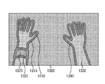
まず、図14におけるカメラ画像1401に対して、例えばソーベル・オペレータを適用し、図13に示すような輪郭線1310、1320、1340を抽出する。なお、輪郭線を抽出する方法としてソーベル・オペレータを適用することに限定されるものではなく、画像から輪郭線を抽出できる方法であれば他の方法も適用可能である。また、本実施形態では、頭部が移動している最中の距離計測値の誤差を低減することを目的としているため、カメラ画像1401にブラーが生じている状態でも輪郭を正しく抽出できるオペレータが望ましい。
First, for example, a Sobel operator is applied to the
さらに、記憶部109に格納されている距離計測部150の移動速度及び移動方向に比例して、抽出した輪郭線を膨張させる。例えば、記憶部109に格納されている距離計測部150の移動速度に比例して膨張量を増やす。距離計測部150による距離計測値は、対象物体である手402L、402Rが時系列的に高速で動くと、対象物体の輪郭における誤差領域が拡大する性質を持つ。このため、信頼度を下げる領域も性質に合わせて拡大させて誤差領域を除去する必要がある。なお、対象物体の形状が時系列的に変化する場合も同様である。
Further, the extracted contour line is expanded in proportion to the moving speed and moving direction of the
また、記憶部109に格納されている距離計測部150の移動方向からカメラ画像1401における対象物体の移動方向を画像の縦方向及び横方向を成分とする2次元ベクトルとして推定する。例えば、予め3次元空間上に仮想の参照点を配置し、カメラ101の直前に計測した位置姿勢とカメラ内部パラメータとから透視投影変換して3次元上の点を投影面に射影して前フレームの投影点とする。次に、現在のカメラ101の位置姿勢とカメラ内部パラメータとから3次元参照点を透視投影して求めた投影面上の点を現在の投影点とする。このように求めた前フレームの投影点と現在の投影点との画像上でのベクトル差を前述した対象物体の移動方向を示す2次元ベクトルとすればよい。なお、距離画像1405における対象物体の移動方向を算出すべきであるが、本実施形態では、距離計測部150及びカメラ101は同一方向に設置されていることを前提としている。
Further, the moving direction of the target object in the
さらに、この2次元ベクトルの縦成分の量を縦の膨張率に比例させ、2次元ベクトルの横成分の量を横の膨張率に比例させる。対象物体である手402L、402Rが一方向に高速で動くと、距離計測値は移動方向に垂直な輪郭領域の誤差領域が拡大する性質を持つため、該当領域の信頼度を下げて誤差領域を除去する必要がある。以上のような処理により、カメラ画像1401に対して図13に示すような輪郭領域1315が算出される。
Further, the amount of the vertical component of the two-dimensional vector is proportional to the vertical expansion coefficient, and the amount of the horizontal component of the two-dimensional vector is proportional to the horizontal expansion coefficient. When the target object hands 402L and 402R move in one direction at high speed, the distance measurement value has the property that the error region of the contour region perpendicular to the moving direction expands. Therefore, the reliability of the corresponding region is lowered and the error region is reduced. Need to be removed. Through the processing as described above, a
次に、ステップS306において、信頼度算出部105は、カメラ画像において、指定された誤差を拡大する色の領域(以後、誤差拡大色領域と呼ぶ)を抽出する。図14に示す例では、まず、カメラ画像1401から黒い領域を抽出する。黒い領域の抽出には、例えば、予め設定した閾値よりも画素の輝度が低い領域を抽出する。そして、スペキュラ成分として距離計測値の誤差を拡大する最高輝度領域の白い領域を抽出する。例えば、カメラ画像1401の輝度成分が8ビットで表現されている場合は、輝度値が255の領域を抽出する。このようにして、カメラ画像1401の黒いリストバンドの領域に対して、図13におけるリストバンドの輪郭線1320の誤差拡大色領域1325を抽出する。
Next, in step S306, the
次に、ステップS307において、信頼度算出部105は、記憶部109に格納されている前フレームのカメラ画像と現在のカメラ画像との差分を求めて差分領域を抽出する。差分領域は、例えば、前フレームのカメラ画像の輝度成分と現在のカメラ画像の輝度成分とを比較し、予め定めた閾値よりも差が大きい場合に対象領域として抽出する。この処理は、距離計測部150が静止している状態で対象が高速移動する場合に出る計測誤差が、前フレームのカメラ画像と現在のカメラ画像との差分領域に類似することを利用している。
Next, in step S307, the
次に、ステップS308において、信頼度算出部105は、ステップS305で算出した輪郭領域、ステップS306で算出した誤差拡大色領域、及びステップS307で算出した差分領域を利用して信頼度画像を生成する。以下、図13に示す信頼度画像1305を生成する処理の詳細について説明する。
Next, in step S308, the
信頼度画像1305は、例えば、カメラ画像1401と同じ解像度を持ち、0〜255の整数値をとる8ビットのグレイスケール画像を用いる。なお、信頼度画像1305は8ビットのグレイスケール画像に限定されるものではない。まず、信頼度画像1305の全画素の初期値として信頼度を255に設定する。次に、ステップS305で算出した輪郭領域に対応する信頼度画像1305の夫々の画素(信頼度)から特定の数値を減算して信頼度を下げる。このように輪郭領域における信頼度を下げて信頼度画像1305を更新する。なお、後述する信頼度に応じて距離画像を抽出する処理で計測誤差の高い領域を抽出できるパラメータであればそれ以外の数値を用いてもよい。また、ステップS305で最初に求めた輪郭線における信頼度が一番低く、輪郭領域の外側へ行くに従って信頼度が高くなるように、減算する値に重みをつけてもよい。
As the
次に、ステップS306で算出した誤差拡大色領域に対応する信頼度画像1305の信頼度から特定の値を減算して信頼度をさらに下げる。さらに、ステップS307で算出した画像差分領域に対応する信頼度画像1305の信頼度から特定の値を減算して信頼度をさらに下げる。上記の減算により、信頼度が負になる場合は、信頼度に0を設定する。以上のような処理により、図13に示すような信頼度画像1305を算出し、信頼度算出部105が記憶部109に格納する。なお、輪郭線1310、1320、1340は説明の便宜上掲載しているものであり、実際の信頼度画像1305には記録されないものである。
Next, the reliability is further lowered by subtracting a specific value from the reliability of the
次に、ステップS309において、距離データ補正部106は、記憶部109に格納されている信頼度画像と距離画像とを用いて、第1の補正として第2の距離データである高信頼度距離画像を生成する。以下、この処理の詳細について図13及び図14に示す例を参照しながら説明する。
Next, in step S309, the distance
図14に示す高信頼度距離画像1410は、例えば、カメラ画像1401と同じ解像度を持ち、0×0000〜0×FFFFの値をとる16ビットのグレイスケール画像を用いる。なお、高信頼度距離画像1410は8ビットのグレイスケール画像に限定されるものではない。高信頼度距離画像1410の全画素の初期値として0×FFFF(無限遠を示す値)を設定する。そして、信頼度画像1305の各画素値にあたる信頼度の値が、予め設定した信頼度の閾値を上回るかどうかを判定する。
The high-
次に、閾値を上回った信頼度画像1305に対応する距離画像1405の距離計測値を求め、高信頼度距離画像1410の値として設定する。なお、信頼度画像1305に対応する距離画像1405の距離計測値を求めるためには、距離画像1405の画像座標系からカメラ画像1401の画像座標系へ変換するホモグラフィ変換行列を利用する。ホモグラフィ変換行列は、予め記憶部109に格納されているものとする。
Next, the distance measurement value of the
なお、カメラ画像1401及び高信頼度距離画像1410は同じ画像座標系であるため、カメラ画像1401から変換する必要はない。また、距離画像1405の解像度が高信頼度距離画像1410の解像度よりも低い場合は、高信頼度距離画像1410に距離計測値を疎にマッピングしたあとに、距離計測値を補間すればよい。このように算出した高信頼度距離画像1410は、距離データ補正部106によって記憶部109に格納される。
Since the
次に、ステップS310において、距離データ補正部106は、第2の補正として、ステップS309で求めた高信頼度距離画像を、ステップS305で最初に求めた輪郭線まで補間処理または補外処理によって補正する。図14に示す例の場合、手402L及びリストバンド410の輪郭線1310、1320、1340は、高信頼度距離画像1410の輪郭1411、1412、1413とは異なる。そこで、ステップS310では、高信頼度距離画像1410の輪郭を輪郭線1310、1320、1340まで拡張する。
Next, in step S310, the distance
まず、距離データ補正部106は、高信頼度距離画像1410の輪郭線上において、カメラ画像1401の輪郭線のある水平方向に向かって距離計測値をコピーして補外する。例えば、図14に示す拡大図K30において、高信頼度距離画像1410の輪郭線1413上にある距離計測値をカメラ画像1401の輪郭線1340に到達するまで右水平方向に同じ値をコピーしていく。距離計測値を水平方向にコピーするのは、距離計測部150が計測する距離画像は水平方向の差が少ないことを仮定しているためである。なお、水平方向に同じ値をコピーすることに限定されるものではなく、例えば、輪郭線1413の内側(左側)の5画素における距離計測値の微分値の平均を求め、同じ微分値になるように輪郭線1413から輪郭線1340までの距離計測値を決定してもよい。
First, the distance
次に、垂直方向に高信頼度距離画像1410を拡張する。垂直方向に拡張する場合も水平方向の処理と同様に、垂直方向に距離計測値をコピーしていく。さらに、輪郭線1310、1320、1340の内部が補正できているかどうかを判定する。図14に示す例では、上記の処理で、リストバンド410の内側の領域1412(輪郭線に囲まれた閉領域で内部の距離計測値が0×FFFFに設定されている領域)が補正されないことが検出される。この判定によって未補正領域が見つかった場合は、カメラ画像1401の輪郭線上の距離計測値を垂直方向に補間する。すなわち、距離データ補正部106は、リストバンド410の輪郭線1320の内側の距離計測値を、垂直方向に補間していく。
Next, the high
このように、距離データ補正部106は、カメラ画像1401の対象物体の輪郭線まで高信頼度距離画像1410を補間及び補外することにより、第3の距離データである補正距離画像1420を算出し、記憶部109に格納する。なお、前述した補間及び補外処理を用いて補正距離画像1420を算出することに限定されるものではなく、例えば、高信頼度距離画像1410を暈すなど、対象物体の輪郭まで正しく補正できる方法であれば他の方法も適用可能である。
As described above, the distance
次に、ステップS311において、仮想画像生成部110は、記憶部109に格納されている仮想物体の3次元モデル情報と補正距離画像とを利用して仮想物体画像を生成する。図14に示す補正距離画像1420を用いた例では、まず、仮想物体の3次元モデル情報をレンダリングし、仮想物体画像の色情報とZバッファ値とを生成する。ここで、仮想物体画像はカメラ画像1401と同一の解像度でレンダリングされるものとする。なお、カメラ画像と仮想物体画像とが同一の解像度であることに限定されるものではなく、仮想物体画像の解像度に合わせてカメラ画像をスケーリング変換してもよい。
Next, in step S <b> 311, the virtual
次に、仮想物体画像のZバッファ値を16ビットで表現できるように変換し、補正距離画像1420の距離計測値と対応する仮想物体画像のZバッファ値とを比較する。この比較の結果、Zバッファ値に対して距離計測値が小さい場合は、仮想物体よりも対象物体が手前にあると仮定して、仮想物体画像の色情報の透明度を1に設定する。逆に、Zバッファよりも距離計測値が大きい場合は、仮想物体の奥に対象物体があると仮定して、仮想物体の色情報の透明度は変更しないようにする。このようにして得られた透明度を含む仮想物体画像は、画像合成部111に出力される。
Next, the Z buffer value of the virtual object image is converted so that it can be expressed in 16 bits, and the distance measurement value of the corrected
次に、ステップS312において、画像合成部111は、カメラ画像と、ステップS311で生成した仮想物体画像とを合成する。ただし、合成処理時には、カメラ画像を背景として仮想物体画像を上書きする。このとき、透明度に応じて背景であるカメラ画像の色と混合する。そして、ステップS312において、画像合成部111は、ステップS312で生成した合成画像をHMD100の表示部103に出力する。
Next, in step S312, the
以上のように本実施形態によれば、このような処理により、図7に示すような仮想物体と現実の物体とが自然に干渉している提示映像を生成することができる。HMD100を装着するMR体験者403が感じる距離感覚に近い映像を提示するので、MR体験者403の没入間の阻害を軽減することができる。
As described above, according to the present embodiment, it is possible to generate a presentation video in which a virtual object and a real object as shown in FIG. Since an image close to the sense of distance felt by the
(第2の実施形態)
前述した第1の実施形態では、カメラ画像1401と距離計測部150の移動速度及び移動方向の情報に基づいて信頼度を決定した。これに対して本実施形態では、距離計測部150から得られる距離データの計測履歴を利用して距離計測値の信頼度を求める方法について説明する。なお、本実施形態における画像処理装置を利用したMR提示システムの構成は、第1の実施形態で説明した図1と基本的には同様である。異なる点としては、本実施形態における信頼度算出部105では、信頼度を算出する際に、カメラ画像を利用せず、距離画像1405の情報から信頼度を算出する点である。
(Second Embodiment)
In the first embodiment described above, the reliability is determined based on the
図15は、本実施形態における画像処理装置を利用したMR提示システムの処理手順の一例を示すフローチャートである。なお、図3と同一番号のものは、第1の実施形態と同一の処理を行うため、第1の実施形態と異なる処理のみを説明する。 FIG. 15 is a flowchart illustrating an example of a processing procedure of the MR presentation system using the image processing apparatus according to the present embodiment. Note that the same reference numerals as those in FIG. 3 perform the same processes as those in the first embodiment, and therefore only the processes different from those in the first embodiment will be described.
ステップS301の処理が行われると、ステップS1501において、距離計測部150が、記憶部109に現在格納されている距離画像を距離画像の履歴として保存し、さらに距離計測部150から得られた新たな距離画像を記憶部109に格納する。
When the process of step S301 is performed, in step S1501, the
ステップS1502においては、信頼度算出部105が、記憶部109に格納された現在の距離画像と前フレームの距離画像とを比較し、差分領域を算出する。この処理は、距離計測結果の誤差が距離画像の差分領域に多く発生する性質を利用して、その領域の信頼度を下げることによって誤差の影響を低減することを目的としている。
In step S1502, the
次に、ステップS1503において、信頼度算出部105は、距離画像における輪郭領域を算出し、輪郭領域の画素(以後、輪郭画素と呼ぶ)ごとに、以下の処理を実施する。まず、現フレームにおける輪郭画素と1フレーム前の距離画像の輪郭領域において一番近い輪郭画素とを対応付ける。さらに、1フレーム前の輪郭画素と2フレーム前の輪郭領域とを比較して1フレーム目の輪郭画素に一番近い画素を対応する輪郭画素とする。同様に5フレーム前までの輪郭画素を対応付けていく。この処理を現フレームの全輪郭領域の画素に対して行う。
Next, in step S1503, the
次に、各輪郭領域の画素ごとに対応付けた5フレーム前までの距離計測値の差分値(微分値)を求める。そして、各フレームにおける差分値の絶対値が閾値を超えて、かつ、差分値の分散が閾値以内である場合に、対象画素の領域を輪郭部変化領域として保存する。この処理は、対象物体が移動するときの距離画像における輪郭線の距離計測値の誤差が、線形的に増加または減少する性質を利用して距離計測誤差を特定するための処理である。すなわち、対象物体の輪郭画素における距離計測値の履歴が線形的に増加・減少している場合は誤差が大きいと判断し、信頼度を下げることによって誤差の影響を低減することを目的としている。 Next, a difference value (differential value) of distance measurement values up to 5 frames before associated with each pixel in each contour region is obtained. Then, when the absolute value of the difference value in each frame exceeds the threshold value and the variance of the difference value is within the threshold value, the region of the target pixel is stored as the contour change region. This process is a process for specifying the distance measurement error by utilizing the property that the error of the distance measurement value of the contour line in the distance image when the target object moves linearly increases or decreases. That is, when the distance measurement value history in the contour pixel of the target object linearly increases / decreases, it is determined that the error is large, and the object is to reduce the influence of the error by lowering the reliability.
次に、ステップS1504において、信頼度算出部105が、ステップS1502で得た距離画像における差分領域と、ステップS1503で算出した輪郭部変化領域とに対応する信頼度画像の領域の信頼度を減少させる。
In step S1504, the
このように、カメラ画像を利用せずに、距離画像における距離計測値の履歴情報を利用して信頼度を算出し、信頼度の低い領域を除去・補正することにより、MR体験者403が感じる距離感に近い映像を提示することができる。
In this way, the
(第3の実施形態)
第1の実施形態では、距離計測部150が距離画像を算出し、距離画像と信頼度画像とに基づいて高信頼度距離画像を生成した。これに対して本実施形態では、距離計測部150が距離画像ではなく、距離画像から変換したポリゴンメッシュを出力する場合に、ポリゴンメッシュと信頼度画像とから高信頼度距離画像を生成する例について説明する。ここで、ポリゴンメッシュとは、距離画像で求めた距離計測値を3次元空間上の点として配置し、各点を接続して仮想物体として描画可能なポリゴンとして再構成したデータを指す。
(Third embodiment)
In the first embodiment, the
本実施形態における画像処理装置を利用したMR提示システムの構成は、第1の実施形態と同一である。ただし、以下の点が異なる。記憶部109では、距離画像1405の代わりにポリゴンメッシュ情報を保持しており、距離データ補正部106ではポリゴンメッシュを入力してポリゴンメッシュのデータを補正する。また、仮想画像生成部110では、ポリゴンメッシュを利用して仮想物体を描画する。
The configuration of the MR presentation system using the image processing apparatus in this embodiment is the same as that in the first embodiment. However, the following points are different. The
図16は、本実施形態における画像処理装置を利用したMR提示システムの処理手順の一例を示すフローチャートである。なお、図3と同一番号のものは、第1の実施形態と同一の処理を行うため、第1の実施形態と異なる処理のみを説明する。 FIG. 16 is a flowchart illustrating an example of a processing procedure of the MR presentation system using the image processing apparatus according to the present embodiment. Note that the same reference numerals as those in FIG. 3 perform the same processes as those in the first embodiment, and therefore only the processes different from those in the first embodiment will be described.
ステップS1601においては、距離データ補正部106は、まず、記憶部109に格納されたカメラ内部パラメータを利用して、ポリゴンメッシュ情報の3次元頂点をカメラ画像の投影面に射影する。そして、信頼度画像とポリゴンメッシュの頂点とを対応付ける。次に、信頼度画像の信頼度のうち、予め指定した閾値に満たない領域に対応するポリゴンメッシュの頂点を削除する。例えば、図11に示すような誤差を持つ3次元ポリゴンメッシュ1010は、図17に示すポリゴンメッシュ1710のように頂点が削除される。
In step S1601, the distance
次に、ステップS1602において、距離データ補正部106は、ステップS1601の処理により残った頂点のうち、ポリゴンメッシュの輪郭となる頂点を1点選択する。そして、カメラ画像の輪郭線上で最も近い点を作成して、その点の距離計測値をその頂点の距離計測値にコピーする。さらに、新規作成した頂点と隣接する頂点とを接続し、ポリゴンメッシュを更新する。同様にメッシュの輪郭となる頂点全てについて、カメラ画像の輪郭線上に新規のメッシュ頂点を作成して接続する。
Next, in step S1602, the distance
さらに、カメラ画像の輪郭線内にポリゴンメッシュの頂点があるかどうかを検証し、頂点がない場合は、輪郭線上にあるポリゴンメッシュの頂点同士を接続して穴を埋める。例えば、リストバンドの誤差拡大色領域1325にはポリゴンメッシュの頂点がないため、リストバンドの輪郭線1320にあるポリゴンメッシュの頂点同士を接続して穴を埋める。このようにしてカメラ画像の輪郭領域と一致するポリゴンメッシュが得られたときに、距離データ補正部106は、ポリゴンメッシュを記憶部109に格納する。
Further, it is verified whether or not there is a vertex of the polygon mesh in the contour line of the camera image. If there is no vertex, the vertexes of the polygon mesh on the contour line are connected to fill the hole. For example, since there is no vertex of the polygon mesh in the error
次に、ステップS1603において、仮想画像生成部110は、記憶部109に格納された仮想物体のモデル情報、更新されたポリゴンメッシュ情報、及びカメラ101の位置姿勢に基づいて、仮想物体画像を生成する。このとき、ポリゴンメッシュの情報のレンダリング表示属性において透明度を1に設定した状態で透明オブジェクトとして描画する。この処理において、Zバッファの比較処理ではポリゴンメッシュの情報と仮想物体のモデル情報との奥行きを比較することにより、仮想物体よりも手前にある現実物体が仮想物体の画像へ上書きされずにMR体験者403に表示されるようにする。
Next, in step S1603, the virtual
このように、距離計測部150の出力を距離画像ではなくポリゴンメッシュで扱う場合であっても、MR体験者403が感じる距離感に近い映像を提示することができる。
Thus, even when the output of the
(その他の実施形態)
また、本発明は、以下の処理を実行することによっても実現される。即ち、上述した実施形態の機能を実現するソフトウェア(プログラム)を、ネットワーク又は各種記憶媒体を介してシステム或いは装置に供給し、そのシステム或いは装置のコンピュータ(またはCPUやMPU等)がプログラムを読み出して実行する処理である。また、当該プログラムを記憶したコンピュータ読み取り可能な記憶媒体も本発明に含まれる。
(Other embodiments)
The present invention can also be realized by executing the following processing. That is, software (program) that realizes the functions of the above-described embodiments is supplied to a system or apparatus via a network or various storage media, and a computer (or CPU, MPU, or the like) of the system or apparatus reads the program. It is a process to be executed. A computer-readable storage medium storing the program is also included in the present invention.
101 カメラ
105 信頼度算出部
106 距離データ補正部
150 距離計測部
Claims (12)
前記物体を含む撮像画像を取得する画像取得手段と、
前記距離計測手段の移動速度および移動方向を取得する取得手段と、
前記撮像画像から前記物体の輪郭領域を抽出する抽出手段と、
前記取得手段によって取得された前記距離計測手段の移動速度および移動方向に基づいて、前記抽出された輪郭領域を拡大する拡大手段と、
前記拡大手段によって拡大された輪郭領域に基づいて、前記第1の距離データにおける計測値の信頼度を算出する信頼度算出手段と、
前記信頼度算出手段によって算出された信頼度に基づいて前記第1の距離データの計測値から信頼度の高い領域を抽出し、前記第1の距離データよりも信頼度の高い第2の距離データを生成する第1の補正手段と、
を備えることを特徴とする画像処理装置。 A distance measuring means for measuring a distance to the object and generating the first distance data;
Image acquisition means for acquiring a captured image including the object;
Obtaining means for obtaining the moving speed and moving direction of the distance measuring means;
Extracting means for extracting a contour region of the object from the captured image;
Enlarging means for enlarging the extracted contour region based on the moving speed and moving direction of the distance measuring means acquired by the acquiring means;
Reliability calculation means for calculating the reliability of the measurement value in the first distance data based on the contour region enlarged by the enlargement means;
A region with high reliability is extracted from the measurement value of the first distance data based on the reliability calculated by the reliability calculation means, and second distance data with higher reliability than the first distance data. First correction means for generating
An image processing apparatus comprising:
前記信頼度算出手段は、前記拡大手段によって拡大された輪郭領域に対応する前記第1の距離データにおける計測値の信頼度および前記色領域に対応する前記第1の距離データにおける計測値の信頼度を、前記輪郭領域以外の領域に対応する前記第1の距離データにおける計測値および前記色領域以外の領域に対応する前記第1の距離データにおける計測値の信頼度よりも低くなるように、前記信頼度を算出することを特徴とする請求項3に記載の画像処理装置。 And a second extracting means for extracting a color region having a luminance value lower than a threshold value from the captured image,
The reliability calculation means is a reliability of the measurement value in the first distance data corresponding to the contour area enlarged by the enlargement means and a reliability of the measurement value in the first distance data corresponding to the color area. Is lower than the reliability of the measurement value in the first distance data corresponding to the region other than the contour region and the measurement value in the first distance data corresponding to the region other than the color region. The image processing apparatus according to claim 3, wherein the reliability is calculated.
前記画像取得手段によって得られた撮像画像と前記仮想画像生成手段によって生成された仮想画像とを合成する合成手段と、
前記合成手段によって合成された合成画像を提示する提示手段と、
を備えることを特徴とする請求項5に記載の画像処理装置。 A virtual image generating unit configured to generate a virtual image based on the position and orientation of the image acquiring unit using the third distance data and the three-dimensional model information of the virtual object;
Combining means for combining the captured image obtained by the image acquisition means and the virtual image generated by the virtual image generation means;
Presenting means for presenting a synthesized image synthesized by the synthesizing means;
The image processing apparatus according to claim 5, further comprising:
前記仮想画像生成手段は、前記ポリゴンを透明オブジェクトとして描画することを特徴とする請求項6又は7に記載の画像処理装置。 The third distance data is a polygon composed of three-dimensional points,
The image processing apparatus according to claim 6, wherein the virtual image generation unit draws the polygon as a transparent object.
前記距離計測手段の移動速度および移動方向を取得する取得工程と、
前記撮像画像から前記物体の輪郭領域を抽出する抽出工程と、
前記取得工程において取得された前記距離計測手段の移動速度および移動方向に基づいて、前記抽出された輪郭領域を拡大する拡大工程と、
前記拡大工程において拡大された輪郭領域に基づいて、前記第1の距離データにおける計測値の信頼度を算出する信頼度算出工程と、
前記信頼度算出工程において算出された信頼度に基づいて前記第1の距離データの計測値から信頼度の高い領域を抽出し、前記第1の距離データよりも信頼度の高い第2の距離データを生成する第1の補正工程と、
を備えることを特徴とする画像処理方法。 An image processing method for an image processing apparatus, comprising: a distance measurement unit that measures a distance to an object and generates first distance data; and an image acquisition unit that acquires a captured image including the object,
An acquisition step of acquiring a moving speed and a moving direction of the distance measuring means;
An extraction step of extracting a contour region of the object from the captured image;
Based on the moving speed and moving direction of the distance measuring means acquired in the acquiring step, an expanding step of expanding the extracted contour region;
A reliability calculation step of calculating the reliability of the measurement value in the first distance data based on the contour region expanded in the expansion step;
A region having high reliability is extracted from the measurement value of the first distance data based on the reliability calculated in the reliability calculation step, and second distance data having higher reliability than the first distance data. A first correction step for generating
An image processing method comprising:
前記距離計測手段の移動速度および移動方向を取得する取得工程と、
前記撮像画像から前記物体の輪郭領域を抽出する抽出工程と、
前記取得工程において取得された前記距離計測手段の移動速度および移動方向に基づいて、前記抽出された輪郭領域を拡大する拡大工程と、
前記拡大工程において拡大された輪郭領域に基づいて、前記第1の距離データにおける計測値の信頼度を算出する信頼度算出工程と、
前記信頼度算出工程において算出された信頼度に基づいて前記第1の距離データの計測値から信頼度の高い領域を抽出し、前記第1の距離データよりも信頼度の高い第2の距離データを生成する第1の補正工程と、
をコンピュータに実行させることを特徴とするプログラム。 A program for controlling an image processing apparatus including a distance measuring unit that measures a distance to an object and generates first distance data, and an image acquisition unit that acquires a captured image including the object,
An acquisition step of acquiring a moving speed and a moving direction of the distance measuring means;
An extraction step of extracting a contour region of the object from the captured image;
Based on the moving speed and moving direction of the distance measuring means acquired in the acquiring step, an expanding step of expanding the extracted contour region;
A reliability calculation step of calculating the reliability of the measurement value in the first distance data based on the contour region expanded in the expansion step;
A region having high reliability is extracted from the measurement value of the first distance data based on the reliability calculated in the reliability calculation step, and second distance data having higher reliability than the first distance data. A first correction step for generating
A program that causes a computer to execute.
Priority Applications (2)
| Application Number | Priority Date | Filing Date | Title |
|---|---|---|---|
| JP2012256463A JP5818773B2 (en) | 2012-11-22 | 2012-11-22 | Image processing apparatus, image processing method, and program |
| US14/086,401 US20140140579A1 (en) | 2012-11-22 | 2013-11-21 | Image processing apparatus capable of generating object distance data, image processing method, and storage medium |
Applications Claiming Priority (1)
| Application Number | Priority Date | Filing Date | Title |
|---|---|---|---|
| JP2012256463A JP5818773B2 (en) | 2012-11-22 | 2012-11-22 | Image processing apparatus, image processing method, and program |
Publications (3)
| Publication Number | Publication Date |
|---|---|
| JP2014106543A JP2014106543A (en) | 2014-06-09 |
| JP2014106543A5 JP2014106543A5 (en) | 2014-12-18 |
| JP5818773B2 true JP5818773B2 (en) | 2015-11-18 |
Family
ID=50727995
Family Applications (1)
| Application Number | Title | Priority Date | Filing Date |
|---|---|---|---|
| JP2012256463A Active JP5818773B2 (en) | 2012-11-22 | 2012-11-22 | Image processing apparatus, image processing method, and program |
Country Status (2)
| Country | Link |
|---|---|
| US (1) | US20140140579A1 (en) |
| JP (1) | JP5818773B2 (en) |
Cited By (2)
| Publication number | Priority date | Publication date | Assignee | Title |
|---|---|---|---|---|
| US10559087B2 (en) | 2016-10-14 | 2020-02-11 | Canon Kabushiki Kaisha | Information processing apparatus and method of controlling the same |
| US11288869B2 (en) | 2017-08-09 | 2022-03-29 | Sony Corporation | Information processing device, and information processing method |
Families Citing this family (39)
| Publication number | Priority date | Publication date | Assignee | Title |
|---|---|---|---|---|
| JP6138566B2 (en) * | 2013-04-24 | 2017-05-31 | 川崎重工業株式会社 | Component mounting work support system and component mounting method |
| JP6489117B2 (en) * | 2014-02-18 | 2019-03-27 | ノーリツプレシジョン株式会社 | Information processing apparatus, information processing method, and program |
| WO2015134795A2 (en) * | 2014-03-05 | 2015-09-11 | Smart Picture Technologies, Inc. | Method and system for 3d capture based on structure from motion with pose detection tool |
| US9626764B2 (en) * | 2014-07-01 | 2017-04-18 | Castar, Inc. | System and method for synchronizing fiducial markers |
| US9858720B2 (en) | 2014-07-25 | 2018-01-02 | Microsoft Technology Licensing, Llc | Three-dimensional mixed-reality viewport |
| US10416760B2 (en) | 2014-07-25 | 2019-09-17 | Microsoft Technology Licensing, Llc | Gaze-based object placement within a virtual reality environment |
| US10311638B2 (en) | 2014-07-25 | 2019-06-04 | Microsoft Technology Licensing, Llc | Anti-trip when immersed in a virtual reality environment |
| US9766460B2 (en) | 2014-07-25 | 2017-09-19 | Microsoft Technology Licensing, Llc | Ground plane adjustment in a virtual reality environment |
| US9904055B2 (en) | 2014-07-25 | 2018-02-27 | Microsoft Technology Licensing, Llc | Smart placement of virtual objects to stay in the field of view of a head mounted display |
| US9865089B2 (en) | 2014-07-25 | 2018-01-09 | Microsoft Technology Licensing, Llc | Virtual reality environment with real world objects |
| US10451875B2 (en) | 2014-07-25 | 2019-10-22 | Microsoft Technology Licensing, Llc | Smart transparency for virtual objects |
| JP6344125B2 (en) * | 2014-07-31 | 2018-06-20 | セイコーエプソン株式会社 | Display device, display device control method, and program |
| US9881422B2 (en) * | 2014-12-04 | 2018-01-30 | Htc Corporation | Virtual reality system and method for controlling operation modes of virtual reality system |
| US10083522B2 (en) | 2015-06-19 | 2018-09-25 | Smart Picture Technologies, Inc. | Image based measurement system |
| JP6650738B2 (en) * | 2015-11-28 | 2020-02-19 | キヤノン株式会社 | Information processing apparatus, information processing system, information processing method and program |
| WO2017104272A1 (en) * | 2015-12-18 | 2017-06-22 | ソニー株式会社 | Information processing device, information processing method, and program |
| US11255663B2 (en) | 2016-03-04 | 2022-02-22 | May Patents Ltd. | Method and apparatus for cooperative usage of multiple distance meters |
| JP6678504B2 (en) * | 2016-04-22 | 2020-04-08 | キヤノン株式会社 | Imaging device, control method therefor, program, and storage medium |
| JP2018160145A (en) * | 2017-03-23 | 2018-10-11 | 富士ゼロックス株式会社 | Three-dimensional measurement device, three-dimensional measurement program, and three-dimensional measurement system |
| WO2019021439A1 (en) | 2017-07-27 | 2019-01-31 | マクセル株式会社 | Imaging component, imaging device, and method for acquiring range image |
| US10304254B2 (en) | 2017-08-08 | 2019-05-28 | Smart Picture Technologies, Inc. | Method for measuring and modeling spaces using markerless augmented reality |
| JP6942566B2 (en) | 2017-08-30 | 2021-09-29 | キヤノン株式会社 | Information processing equipment, information processing methods and computer programs |
| JP6878219B2 (en) * | 2017-09-08 | 2021-05-26 | 株式会社東芝 | Image processing device and ranging device |
| JP7057097B2 (en) * | 2017-10-27 | 2022-04-19 | キヤノン株式会社 | Control methods and programs for distance measuring devices, distance measuring systems, imaging devices, moving objects, and distance measuring devices |
| JP6835455B2 (en) * | 2017-12-25 | 2021-02-24 | Kddi株式会社 | Programs, devices and methods for correcting depth values in time-series depth images |
| JP7173762B2 (en) * | 2018-06-19 | 2022-11-16 | 株式会社トプコン | Reflector position calculation device, reflector position calculation method, and reflector position calculation program |
| US10699430B2 (en) * | 2018-10-09 | 2020-06-30 | Industrial Technology Research Institute | Depth estimation apparatus, autonomous vehicle using the same, and depth estimation method thereof |
| WO2020115866A1 (en) * | 2018-12-06 | 2020-06-11 | 株式会社DeepX | Depth processing system, depth processing program, and depth processing method |
| JP7028814B2 (en) * | 2019-02-07 | 2022-03-02 | ファナック株式会社 | External shape recognition device, external shape recognition system and external shape recognition method |
| WO2020231872A1 (en) | 2019-05-10 | 2020-11-19 | Smart Picture Technologies, Inc. | Methods and systems for measuring and modeling spaces using markerless photo-based augmented reality process |
| US20220414945A1 (en) * | 2019-12-10 | 2022-12-29 | Sony Group Corporation | Image processing device, image processing method, and program |
| US11205296B2 (en) * | 2019-12-20 | 2021-12-21 | Sap Se | 3D data exploration using interactive cuboids |
| USD959476S1 (en) | 2019-12-20 | 2022-08-02 | Sap Se | Display system or portion thereof with a virtual three-dimensional animated graphical user interface |
| USD959447S1 (en) | 2019-12-20 | 2022-08-02 | Sap Se | Display system or portion thereof with a virtual three-dimensional animated graphical user interface |
| USD959477S1 (en) | 2019-12-20 | 2022-08-02 | Sap Se | Display system or portion thereof with a virtual three-dimensional animated graphical user interface |
| WO2021145068A1 (en) * | 2020-01-17 | 2021-07-22 | ソニーグループ株式会社 | Information processing device and information processing method, computer program, and augmented reality system |
| JP7446888B2 (en) | 2020-03-30 | 2024-03-11 | 日産自動車株式会社 | Image generation device and image generation method |
| JP7079833B2 (en) * | 2020-12-03 | 2022-06-02 | マクセル株式会社 | Mobile information terminal |
| JP2022155843A (en) * | 2021-03-31 | 2022-10-14 | Johnan株式会社 | Posture estimation system |
Family Cites Families (12)
| Publication number | Priority date | Publication date | Assignee | Title |
|---|---|---|---|---|
| JP4296617B2 (en) * | 1998-10-15 | 2009-07-15 | ソニー株式会社 | Image processing apparatus, image processing method, and recording medium |
| JP3728160B2 (en) * | 1999-12-06 | 2005-12-21 | キヤノン株式会社 | Depth image measuring apparatus and method, and mixed reality presentation system |
| US6834232B1 (en) * | 2003-07-30 | 2004-12-21 | Ford Global Technologies, Llc | Dual disimilar sensing object detection and targeting system |
| JP4696991B2 (en) * | 2006-03-22 | 2011-06-08 | 日産自動車株式会社 | Motion detection method and motion detection apparatus |
| JP5025496B2 (en) * | 2008-01-09 | 2012-09-12 | キヤノン株式会社 | Image processing apparatus and image processing method |
| JP5448617B2 (en) * | 2008-08-19 | 2014-03-19 | パナソニック株式会社 | Distance estimation device, distance estimation method, program, integrated circuit, and camera |
| JP5567908B2 (en) * | 2009-06-24 | 2014-08-06 | キヤノン株式会社 | Three-dimensional measuring apparatus, measuring method and program |
| JP5624998B2 (en) * | 2009-12-25 | 2014-11-12 | 本田技研工業株式会社 | Image processing apparatus, image processing method, computer program, and moving body |
| JP5618569B2 (en) * | 2010-02-25 | 2014-11-05 | キヤノン株式会社 | Position and orientation estimation apparatus and method |
| JP2012058968A (en) * | 2010-09-08 | 2012-03-22 | Namco Bandai Games Inc | Program, information storage medium and image generation system |
| JP5533529B2 (en) * | 2010-10-06 | 2014-06-25 | コニカミノルタ株式会社 | Image processing apparatus and image processing system |
| CN103221977B (en) * | 2010-12-09 | 2015-10-14 | 松下电器产业株式会社 | Posture state estimation unit and posture state method of estimation |
-
2012
- 2012-11-22 JP JP2012256463A patent/JP5818773B2/en active Active
-
2013
- 2013-11-21 US US14/086,401 patent/US20140140579A1/en not_active Abandoned
Cited By (2)
| Publication number | Priority date | Publication date | Assignee | Title |
|---|---|---|---|---|
| US10559087B2 (en) | 2016-10-14 | 2020-02-11 | Canon Kabushiki Kaisha | Information processing apparatus and method of controlling the same |
| US11288869B2 (en) | 2017-08-09 | 2022-03-29 | Sony Corporation | Information processing device, and information processing method |
Also Published As
| Publication number | Publication date |
|---|---|
| US20140140579A1 (en) | 2014-05-22 |
| JP2014106543A (en) | 2014-06-09 |
Similar Documents
| Publication | Publication Date | Title |
|---|---|---|
| JP5818773B2 (en) | Image processing apparatus, image processing method, and program | |
| CN109561296B (en) | Image processing apparatus, image processing method, image processing system, and storage medium | |
| US9767611B2 (en) | Information processing apparatus and method for estimating depth values using an approximate plane | |
| JP4401727B2 (en) | Image display apparatus and method | |
| KR101560508B1 (en) | Method and arrangement for 3-dimensional image model adaptation | |
| US9224245B2 (en) | Mesh animation | |
| JP5762600B1 (en) | Information processing apparatus and information processing method | |
| JP7197451B2 (en) | Image processing device, method and program | |
| JP2013235537A (en) | Image creation device, image creation program and recording medium | |
| US11830148B2 (en) | Reconstruction of essential visual cues in mixed reality applications | |
| JP2009211513A (en) | Image processing apparatus and method therefor | |
| JP2016071645A (en) | Object three-dimensional model restoration method, device, and program | |
| Fischer et al. | A hybrid tracking method for surgical augmented reality | |
| KR101566459B1 (en) | Concave surface modeling in image-based visual hull | |
| WO2020084312A1 (en) | Method and system for providing at least a portion of content having six degrees of freedom motion | |
| KR100447778B1 (en) | Apparatus for Embodying Stereo/Multiview Realistic Mixed Reality using Pose Estimation and Method Thereof | |
| JP2006343953A (en) | Image processing method and image processing device | |
| JP2021047468A (en) | Image processing equipment, image processing method, and image processing program | |
| Jang et al. | Depth video based human model reconstruction resolving self-occlusion | |
| JP7465133B2 (en) | Information processing device and information processing method | |
| WO2023120217A1 (en) | Information processing device, information processing method, and program | |
| US20220309733A1 (en) | Surface texturing from multiple cameras | |
| US11983814B2 (en) | Image processing apparatus that generates model of object, image processing method, and storage medium storing program thereof | |
| JP7175715B2 (en) | Information processing device, information processing method and program | |
| US20220230393A1 (en) | Image processing apparatus that generates model of object, image processing method, and storage medium storing program thereof |
Legal Events
| Date | Code | Title | Description |
|---|---|---|---|
| A521 | Request for written amendment filed |
Free format text: JAPANESE INTERMEDIATE CODE: A523 Effective date: 20141031 |
|
| A621 | Written request for application examination |
Free format text: JAPANESE INTERMEDIATE CODE: A621 Effective date: 20141031 |
|
| A131 | Notification of reasons for refusal |
Free format text: JAPANESE INTERMEDIATE CODE: A131 Effective date: 20150106 |
|
| A521 | Request for written amendment filed |
Free format text: JAPANESE INTERMEDIATE CODE: A523 Effective date: 20150304 |
|
| A131 | Notification of reasons for refusal |
Free format text: JAPANESE INTERMEDIATE CODE: A131 Effective date: 20150609 |
|
| A521 | Request for written amendment filed |
Free format text: JAPANESE INTERMEDIATE CODE: A523 Effective date: 20150804 |
|
| TRDD | Decision of grant or rejection written | ||
| A01 | Written decision to grant a patent or to grant a registration (utility model) |
Free format text: JAPANESE INTERMEDIATE CODE: A01 Effective date: 20150901 |
|
| A61 | First payment of annual fees (during grant procedure) |
Free format text: JAPANESE INTERMEDIATE CODE: A61 Effective date: 20150929 |
|
| R151 | Written notification of patent or utility model registration |
Ref document number: 5818773 Country of ref document: JP Free format text: JAPANESE INTERMEDIATE CODE: R151 |