JP4502362B2 - Inkjet recording method, inkjet recording system, inkjet recording apparatus, and control program - Google Patents
Inkjet recording method, inkjet recording system, inkjet recording apparatus, and control program Download PDFInfo
- Publication number
- JP4502362B2 JP4502362B2 JP2003343690A JP2003343690A JP4502362B2 JP 4502362 B2 JP4502362 B2 JP 4502362B2 JP 2003343690 A JP2003343690 A JP 2003343690A JP 2003343690 A JP2003343690 A JP 2003343690A JP 4502362 B2 JP4502362 B2 JP 4502362B2
- Authority
- JP
- Japan
- Prior art keywords
- recording
- data
- areas
- mode
- dots
- Prior art date
- Legal status (The legal status is an assumption and is not a legal conclusion. Google has not performed a legal analysis and makes no representation as to the accuracy of the status listed.)
- Expired - Fee Related
Links
Images


Classifications
-
- B—PERFORMING OPERATIONS; TRANSPORTING
- B41—PRINTING; LINING MACHINES; TYPEWRITERS; STAMPS
- B41J—TYPEWRITERS; SELECTIVE PRINTING MECHANISMS, i.e. MECHANISMS PRINTING OTHERWISE THAN FROM A FORME; CORRECTION OF TYPOGRAPHICAL ERRORS
- B41J2/00—Typewriters or selective printing mechanisms characterised by the printing or marking process for which they are designed
- B41J2/005—Typewriters or selective printing mechanisms characterised by the printing or marking process for which they are designed characterised by bringing liquid or particles selectively into contact with a printing material
- B41J2/01—Ink jet
- B41J2/205—Ink jet for printing a discrete number of tones
- B41J2/2054—Ink jet for printing a discrete number of tones by the variation of dot disposition or characteristics, e.g. dot number density, dot shape
Landscapes
- Ink Jet (AREA)
- Particle Formation And Scattering Control In Inkjet Printers (AREA)
Description
本発明は、記録媒体に記録材を記録することによって所定の濃度情報を表現することが可能なインクジェット記録方法、インクジェット記録システム、インクジェット記録装置および制御プログラムに関する。 The present invention relates to an ink jet recording method, an ink jet recording system, an ink jet recording apparatus, and a control program capable of expressing predetermined density information by recording a recording material on a recording medium.
近年来のパーソナルコンピュータ等情報処理機器の普及に伴い、画像形成端末としての記録装置も急速に発展および普及してきた。特に種々の記録装置の中でも、吐出口からインクを吐出させて紙、布、プラスチックシート、OHP用シートなどの記録媒体に記録を行うインクジェット記録装置は、低騒音のノンインパクト型の記録方式であること、高密度かつ高速な記録動作が可能であること、カラー記録にも容易に対応できること、低廉であることなど、極めて優れた特長を有しており、今やパーソナルユースの記録装置の主流となっている。 With the recent spread of information processing equipment such as personal computers, recording devices as image forming terminals have been rapidly developed and spread. In particular, among various recording apparatuses, an ink jet recording apparatus that performs recording on a recording medium such as paper, cloth, a plastic sheet, and an OHP sheet by ejecting ink from an ejection port is a low-noise non-impact recording method. It has excellent features such as high-density and high-speed recording operations, easy compatibility with color recording, and low cost, and is now the mainstream of personal-use recording devices. ing.
インクジェット記録技術の進歩は記録の高画質化、高速化、低廉化を促進し、またパーソナルコンピュータやデジタルカメラ(単体でその機能を果たすもののほか、その他の装置、例えば携帯型電話に一体化されるものも含む)の普及とも相俟って、パーソナルユーザにまで記録装置を普及させる効果に寄与すること大であった。しかしそのような広範な普及により、パーソナルユーザからも画質のより一層の向上が求められるようになってきており、特に近年では、家庭で手軽に写真をプリントできるようなプリントシステムおよび銀塩写真に見合う画像の品位が求められて来ている。 Advances in ink-jet recording technology have promoted higher image quality, higher speed, and lower cost of recording, and can be integrated into personal computers and digital cameras (which function alone as well as other devices such as mobile phones) In addition to the widespread use of the recording apparatus, it has been a great contribution to the effect of spreading the recording apparatus to personal users. However, with such widespread use, personal users are demanding further improvements in image quality. Especially in recent years, printing systems and silver halide photography that can easily print photos at home are used. There is a demand for quality images that match.
いわゆる一般的な銀塩写真と比べた場合、インクジェット記録装置においては、それ特有の粒状感がかねてから問題視されていた。よって近年ではこの粒状感を低減するための様々な対策が提案されており、その様な対策が盛り込まれた記録装置も多く提供されている。たとえば、通常のシアン、マゼンタ、イエローおよびブラックの外に、より濃度の低いライトシアンやライトマゼンタを加えたインクシステムを具備するインクジェット記録装置がある。このようなインクシステムであれば、濃度の低い領域でライトシアンやライトマゼンタを用いることにより、粒状感を低減することができる。また、濃度の高い領域では通常のシアンおよびマゼンタで記録を行うことにより、より広い色再現および滑らかな階調性を実現させることが可能となっている。 Compared with so-called general silver salt photographs, the inkjet recording apparatus has been regarded as a problem for a long time because of its unique graininess. Therefore, various measures for reducing the graininess have been proposed in recent years, and many recording apparatuses incorporating such measures have been provided. For example, there is an ink jet recording apparatus including an ink system in which light cyan or light magenta having a lower density is added in addition to normal cyan, magenta, yellow, and black. With such an ink system, graininess can be reduced by using light cyan or light magenta in a low density region. Further, in a high density region, it is possible to realize wider color reproduction and smooth gradation by recording with normal cyan and magenta.
更に、記録媒体に着弾されるドットの大きさをより小さく設計して粒状感を低減する方法もあり、このために記録ヘッドに配列する各記録素子から吐出されるインク滴を少量化する技術も進められて来ている。この場合、インク滴の少量化のみならず、より多くの記録素子をより高い配列密度によって構成することにより、記録速度を損なわずに高解像な画像を同時に得ることが可能となっている。 Furthermore, there is a method for reducing the graininess by designing the size of the dots that land on the recording medium to be smaller, and for this purpose, there is also a technique for reducing the amount of ink droplets ejected from each recording element arranged in the recording head. It has been advanced. In this case, not only a small amount of ink droplets but also a larger number of recording elements having a higher arrangement density makes it possible to simultaneously obtain a high-resolution image without impairing the recording speed.
ところで、パーソナルユースのインクジェット記録装置においては、上述したように写真画質に迫る高品位な画像の出力が求められる一方で、テキストや図表のような通常の文書を出力する場合も少なくない。そして、このような文書においては、銀塩写真並みの画像品位よりも、むしろ高速に出力することが肝要とされるのである。よって、一般のインクジェット記録装置では、複数の記録モードを具備しておきながら、用途に応じてユーザがこれを設定可能とする構成となっている(例えば、特許文献1参照。)。 By the way, as described above, a personal-use inkjet recording apparatus is required to output a high-quality image close to a photographic image quality, but a normal document such as a text or a diagram is often output. In such a document, it is important to output at a high speed rather than image quality similar to silver halide photography. Therefore, a general ink jet recording apparatus has a configuration in which a user can set a plurality of recording modes in accordance with the use while having a plurality of recording modes (see, for example, Patent Document 1).
しかしながら、上記のような画質向上への技術開発は、必ずしも低廉化や高速出力を重視する記録モードと共存できるものばかりではなかった。たとえば、記録素子から吐出されるインクの量(以下吐出量と称す)を変調できない構成のインクジェット記録装置においては、粒状感を低減するために、記録ヘッドに配列する各記録素子から吐出される全てのインク滴が固定量の小ドロップとなっている。そして、この決められた吐出量で記録されるドットを、好ましい密度に配列させることによって、所望の濃度が得られるように設計されている(例えば、特許文献2参照。)。よって、吐出量が小さくなればなるほど、所望の濃度を得るための記録密度が高くなり、そのための構成手段やデータの処理も、複雑でありながら、ある程度固定的に確立されてしまっているのである。従って、より高速に出力したいモードにおいても、所定の濃度を得るためには、上記構成手段やデータの処理方法に依存して記録せざるを得ない状況にあり、十分な濃度を満足のいく記録速度で得ることが困難な状況であった。 However, the technical development for improving the image quality as described above has not always been able to coexist with a recording mode in which cost reduction and high-speed output are important. For example, in an ink jet recording apparatus having a configuration in which the amount of ink ejected from a recording element (hereinafter referred to as ejection amount) cannot be modulated, in order to reduce graininess, all the ink ejected from each recording element arranged in the recording head is used. The ink droplets are small drops of a fixed amount. And it is designed so that a desired density can be obtained by arranging the dots to be recorded with the determined discharge amount at a preferable density (see, for example, Patent Document 2). Therefore, the smaller the ejection amount, the higher the recording density for obtaining a desired density, and the construction means and data processing for that purpose are complicated and fixedly established to some extent. . Therefore, even in a mode where it is desired to output at a higher speed, in order to obtain a predetermined density, there is a situation in which recording must be performed depending on the configuration means and the data processing method, and sufficient density can be recorded. It was a difficult situation to get at speed.
本発明は上述の問題点を解消するためになされたものであり、その目的とするところは、小ドロップを実現する所定の吐出量に固定されたインクジェット記録ヘッドを用いながら、上記吐出量から得られる好適な記録密度よりも低い記録密度でデータ処理および記録を行いつつ、所望の画像濃度を得ることが可能なインクジェット記録方法、インクジェット記録システム、インクジェット記録装置、および当該記録方法を実現するための制御プログラムを提供することである。 The present invention has been made to solve the above-described problems, and the object of the present invention is to obtain from the above-mentioned discharge amount while using an ink jet recording head fixed to a predetermined discharge amount that realizes a small drop. INK JET RECORDING METHOD, INK JET RECORDING SYSTEM, INK JET RECORDING APPARATUS, AND ITS RECORDING METHOD It is to provide a control program.
そのために本発明では、吐出データに従ってインクを吐出する記録ヘッドを記録媒体の画素領域に対し複数回走査させることによって画像を記録するインクジェット記録方法であって、
前記記録ヘッドのN回(Nは2以上の整数)の走査によって画素領域に画像を記録するための第1モードと、前記記録ヘッドのM回(MはNより大きな整数)の走査によって画素領域に画像を記録するための第2モードと、を含む複数の記録モードの中から実行すべき記録モードを設定する工程を有し、
前記第1記録モードは、
A−i)前記画素領域に対応する多値の階調データをK値(Kは2以上の整数)の階調データに量子化する第1量子化工程と、
A−ii)K階調用のドット配置パターンを用いて、前記K値の階調データを、前記画素領域を構成するJ個(Jは2以上の整数)のエリア夫々に対する記録ドットの有無を定める第1の2値データに変換する第1の2値化工程と、
A−iii)前記N回の走査において前記第1の2値データの記録が許容されるエリアの和がJ個よりも多くなるように前記第1の2値データにマスク処理を行うための第1のマスクパターンを用いて、前記第1の2値データから前記N回の走査それぞれに対応した第1の吐出データを作成する工程と、
A−iv)前記N回の走査において前記第1の吐出データに従ってドットの記録を行う工程と、を含み、
前記第1の記録モードによって前記J個のエリアで構成される画素領域に記録され得るドット数の最大値がJ個より大きく、且つ、
前記第2記録モードは、
B−i)前記画素領域に対応する多値の階調データをL値(LはKより大きな整数)の階調データに変換する第2量子化工程と、
B−ii)L階調用のドット配置パターンを用いて、前記L値の階調データを、前記画素を構成するH個(HはJより大きな整数)のエリア夫々に対する記録ドットの有無を定める第2の2値データに変換する第2の2値化工程と、
B−iii)前記M回の走査において前記第1の2値データの記録が許容されるエリアの和がH個と等しくなるように前記第1の2値データにマスク処理を行うための第2のマスクパターンを用いて、前記第2の2値データから前記M回の走査それぞれに対応した第2の吐出データを作成する工程と、
B−iv)前記M回の走査において前記第2の吐出データに従ってドットの記録を行う工程と、を含み、
前記第2の記録モードによって前記H個のエリアで構成される画素領域に記録され得るドット数の最大値はH個と等しい
ことを特徴とする。
Therefore, in the present invention, an inkjet recording method for recording an image by causing a recording head that ejects ink according to ejection data to scan a pixel region of a recording medium a plurality of times,
A first mode for recording an image in a pixel area by N times (N is an integer of 2 or more) of the recording head, and a pixel area by M times (M is an integer larger than N) of the recording head. A step of setting a recording mode to be executed from a plurality of recording modes including a second mode for recording an image on
The first recording mode is:
Ai) a first quantization step of quantizing multi-value gradation data corresponding to the pixel region into gradation data of K value (K is an integer of 2 or more);
A-ii) Using a dot arrangement pattern for K gradation, the presence or absence of a recording dot is determined for each of J (J is an integer of 2 or more) areas of the K value gradation data. A first binarization step for converting to first binary data;
A-iii) A first process for performing mask processing on the first binary data so that the sum of areas in which the recording of the first binary data is allowed in the N scans is larger than J. Creating first ejection data corresponding to each of the N scans from the first binary data using one mask pattern;
A-iv) recording dots according to the first ejection data in the N scans,
The maximum number of dots that can be recorded in the pixel area composed of the J areas in the first recording mode is greater than J, and
The second recording mode is:
Bi) a second quantization step of converting multi-value gradation data corresponding to the pixel region into gradation data of L value (L is an integer larger than K);
B-ii) A dot arrangement pattern for L gradation is used to determine whether or not there is a recording dot for each of H areas (H is an integer greater than J) of the L value gradation data. A second binarization step for converting into binary binary data;
B-iii) Second for masking the first binary data so that the sum of the areas in which the printing of the first binary data is allowed in the M scans is equal to H. Using the mask pattern to create second ejection data corresponding to each of the M scans from the second binary data;
B-iv) recording dots according to the second ejection data in the M scans,
The maximum number of dots that can be recorded in the pixel area constituted by the H areas in the second recording mode is equal to H.
また、吐出データに従ってインクを吐出する記録ヘッドを記録媒体の画素領域に対し複数回走査させることによって画像を記録するインクジェット記録装置であって、
前記記録ヘッドのN回(Nは2以上の整数)の走査によって画素領域に画像を記録するための第1モードと、前記記録ヘッドのM回(MはNより大きな整数)の走査によって画素領域に画像を記録するための第2モードと、を含む複数の記録モードの中から実行すべき記録モードを設定する手段を備え、
前記第1記録モードは、
A−i)前記画素領域に対応する多値の階調データをK値(Kは2以上の整数)の階調データに量子化し、
A−ii)K階調用のドット配置パターンを用いて、前記K値の階調データを、前記画素領域を構成するJ個(Jは2以上の整数)のエリア夫々に対する記録ドットの有無を定める第1の2値データに変換し、
A−iii)前記N回の走査において前記第1の2値データの記録が許容されるエリアの和がJ個よりも多くなるように前記第1の2値データにマスク処理を行うための第1のマスクパターンを用いて前記第1の2値データから前記N回の走査それぞれに対応した第1の吐出データを作成し、
A−iv)前記N回の走査において前記第1の吐出データに従ってドットの記録を行うモードであり、
前記第1の記録モードによって前記J個のエリアで構成される画素領域に記録され得るドット数の最大値がJ個より大きく、且つ、
前記第2記録モードは、
B−i)前記画素領域に対応する多値の階調データをL値(LはKより大きな整数)の階調データに変換し、
B−ii)L階調用のドット配置パターンを用いて、前記L値の階調データを、前記画素領域を構成するH個(HはJより大きな整数)のエリア夫々に対する記録ドットの有無を定める第2の2値データに変換し、
B−iii)前記M回の走査において前記第1の2値データの記録が許容されるエリアの和がH個と等しくなるように前記第1の2値データにマスク処理を行うための第2のマスクパターンを用いて、前記第2の2値データから前記M回の走査それぞれに対応した第2の吐出データを作成し、
B−iv)前記M回の走査において前記第2の吐出データに従ってドットの記録を行うモードであり、
前記第1の記録モードによって前記H個のエリアで構成される画素領域に記録され得るドット数の最大値はH個と等しい
ことを特徴とする。
An inkjet recording apparatus that records an image by causing a recording head that ejects ink according to ejection data to scan a pixel area of a recording medium a plurality of times,
A first mode for recording an image in a pixel area by N times (N is an integer of 2 or more) of the recording head, and a pixel area by M times (M is an integer larger than N) of the recording head. Means for setting a recording mode to be executed from a plurality of recording modes including a second mode for recording an image on
The first recording mode is:
Ai) Quantize multi-value gradation data corresponding to the pixel area into gradation data of K value (K is an integer of 2 or more);
A-ii) Using a dot arrangement pattern for K gradation, the presence or absence of a recording dot is determined for each of J (J is an integer of 2 or more) areas of the K value gradation data. Converted to first binary data,
A-iii) A first process for performing mask processing on the first binary data so that the sum of areas in which the recording of the first binary data is allowed in the N scans is larger than J. Creating first ejection data corresponding to each of the N scans from the first binary data using one mask pattern;
A-iv) A mode in which dots are recorded according to the first ejection data in the N scans.
The maximum number of dots that can be recorded in the pixel area composed of the J areas in the first recording mode is greater than J, and
The second recording mode is:
B-i) Multi-value gradation data corresponding to the pixel region is converted into gradation data of L value (L is an integer larger than K);
B-ii) Using a dot arrangement pattern for L gradation, the presence or absence of a recording dot is determined for each of H areas (H is an integer larger than J) in the L value gradation data. Converted into second binary data,
B-iii) Second for masking the first binary data so that the sum of the areas in which the printing of the first binary data is allowed in the M scans is equal to H. Second ejection data corresponding to each of the M scans is created from the second binary data using the mask pattern of
B-iv) A mode in which dots are recorded in accordance with the second ejection data in the M scans.
The maximum number of dots that can be recorded in the pixel area constituted by the H areas in the first recording mode is equal to H.
更に、吐出データに従ってインクを吐出する記録ヘッドを記録媒体の画素領域に対し複数回走査させることによって画像を記録するインクジェット記録装置であって、
前記記録ヘッドのN回(Nは2以上の整数)の走査によって画素領域に画像を記録するための第1モードと、前記記録ヘッドのM回(MはNより大きな整数)の走査によって画素領域に画像を記録するための第2モードと、を含む複数の記録モードの中から実行すべき記録モードを設定する手段を備え、
前記第1記録モードは、
A−i)前記画素領域に対応する多値の階調データをK値(Kは2以上の整数)の階調データに量子化し、
A−ii)K階調用のドット配置パターンを用いて、前記K値の階調データを、前記画素領域を構成するJ個(Jは2以上の整数)のエリア夫々に対する記録ドットの有無を定める第1の2値データに変換し、
A−iii)前記N回の走査において前記第1の2値データの記録が許容されるエリアの和がJ個よりも多くなるように前記第1の2値データにマスク処理を行うための第1のマスクパターンを用いて前記第1の2値データから前記N回の走査それぞれに対応した第1の吐出データを作成し、
A−iv)前記N回の走査において前記第1の吐出データに従ってドットの記録を行うモードであり、
前記第1の記録モードによって前記J個のエリアで構成される画素領域に記録され得るドット数の最大値がJ個より大きく、且つ、
前記第2記録モードは、
B−i)前記画素領域に対応する多値の階調データをL値(LはKより大きな整数)の階調データに変換し、
B−ii)L階調用のドット配置パターンを用いて、前記L値の階調データを、前記画素領域を構成するH個(HはJより大きな整数)のエリア夫々に対する記録ドットの有無を定める第2の2値データに変換し、
B−iii)前記M回の走査において前記第1の2値データの記録が許容されるエリアの和がH個と等しくなるように前記第1の2値データにマスク処理を行うための第2のマスクパターンを用いて、前記第2の2値データから前記M回の走査それぞれに対応した第2の吐出データを作成し、
B−iv)前記M回の走査において前記第2の吐出データに従ってドットの記録を行うモードであり、前記第1の記録モードによって前記H個のエリアで構成される画素領域に記録され得るドット数の最大値はH個と等しい
ことを特徴とする。
Furthermore, an inkjet recording apparatus that records an image by causing a recording head that ejects ink according to ejection data to scan a pixel area of a recording medium a plurality of times,
A first mode for recording an image in a pixel area by N times (N is an integer of 2 or more) of the recording head, and a pixel area by M times (M is an integer larger than N) of the recording head. Means for setting a recording mode to be executed from a plurality of recording modes including a second mode for recording an image on
The first recording mode is:
Ai) Quantize multi-value gradation data corresponding to the pixel area into gradation data of K value (K is an integer of 2 or more);
A-ii) Using a dot arrangement pattern for K gradation, the presence or absence of a recording dot is determined for each of J (J is an integer of 2 or more) areas of the K value gradation data. Converted to first binary data,
A-iii) A first process for performing mask processing on the first binary data so that the sum of areas in which the recording of the first binary data is allowed in the N scans is larger than J. Creating first ejection data corresponding to each of the N scans from the first binary data using one mask pattern;
A-iv) A mode in which dots are recorded according to the first ejection data in the N scans.
The maximum number of dots that can be recorded in the pixel area composed of the J areas in the first recording mode is greater than J, and
The second recording mode is:
B-i) Multi-value gradation data corresponding to the pixel region is converted into gradation data of L value (L is an integer larger than K);
B-ii) Using a dot arrangement pattern for L gradation, the presence or absence of a recording dot is determined for each of H areas (H is an integer larger than J) in the L value gradation data. Converted into second binary data,
B-iii) Second for masking the first binary data so that the sum of the areas in which the printing of the first binary data is allowed in the M scans is equal to H. Second ejection data corresponding to each of the M scans is created from the second binary data using the mask pattern of
B-iv) A mode in which dots are recorded in accordance with the second ejection data in the M scans, and the number of dots that can be recorded in the pixel area composed of the H areas in the first recording mode. The maximum value of is equal to H.
本発明によれば、各画素に対し、ドット配置パターンで得られる以上の所定数のドットを濃度値に応じて記録することが出来るので、従来のドット配置パターンに比べてより高い濃度および階調性で画像を記録することが出来る。よって、小ドロップを実現する所定の吐出量に固定されたインクジェット記録ヘッドを用いながらも、上記吐出量から得られる好適な記録密度よりも低い画素密度でデータ処理および記録を行いつつ、所望の画像濃度を得ることが可能となる。 According to the present invention, since a predetermined number of dots larger than those obtained by the dot arrangement pattern can be recorded for each pixel according to the density value, higher density and gradation than the conventional dot arrangement pattern can be obtained. It is possible to record an image with sex. Therefore, while using an inkjet recording head fixed to a predetermined discharge amount that realizes a small drop, a desired image is obtained while performing data processing and recording at a pixel density lower than a suitable recording density obtained from the discharge amount. The concentration can be obtained.
(第1の実施形態)
以下に、本発明の第1実施形態を詳細に説明する。
図1は、本実施形態における画像データ変換処理の流れを説明するためのブロック図である。本実施形態で適用するインクジェット記録装置は、シアン、マゼンタ、イエロー、ブラックの基本色であるインクのほかに、レッド、ライトシアンおよびライトマゼンタによって記録を行うものであり、そのためにこれら6色のインクを吐出する記録ヘッドが用意されている。図1に示すように、ここに示す各処理は、記録装置とホスト装置としてのパーソナルコンピュータ(PC)によって構成されるものとする。
(First embodiment)
The first embodiment of the present invention will be described in detail below.
FIG. 1 is a block diagram for explaining the flow of image data conversion processing in the present embodiment. The ink jet recording apparatus applied in this embodiment performs recording with red, light cyan, and light magenta in addition to inks that are basic colors of cyan, magenta, yellow, and black. For this purpose, these six colors of ink are used. A recording head for discharging is prepared. As shown in FIG. 1, each process shown here is assumed to be constituted by a recording device and a personal computer (PC) as a host device.
ホスト装置のオペレーティングシステムで動作するプログラムとしてアプリケーションやプリンタドライバがあり、アプリケーションJ0001は記録装置で記録する画像データを作成する処理を実行する。実際の記録時にはアプリケーションで作成された画像データがプリンタドライバに渡される。 There are an application and a printer driver as programs that operate in the operating system of the host device. At the time of actual recording, image data created by the application is passed to the printer driver.
本実施形態の記録システムにおいては、用途に応じてユーザが記録モードをプリンタドライバから選択できるようになっている。本実施形態では高画質写真モードおよび高速モードの少なくとも2つの記録モードが選択可能であるとし、プリンタドライバ以降の各処理は、記録モードに応じてある程度独立に設計可能なものとする。 In the recording system of this embodiment, the user can select the recording mode from the printer driver according to the application. In the present embodiment, it is assumed that at least two recording modes, that is, a high-quality photo mode and a high-speed mode, can be selected, and each process after the printer driver can be designed to some extent independently according to the recording mode.
以下に、まず、高画質写真モードで記録する場合の処理を説明する。 In the following, a process for recording in the high-quality photo mode will be described first.
本実施形態におけるプリンタドライバはその処理として、前段処理J0002、後段処理J0003、γ補正J0004、ハーフトーニングJ0005、および印刷データ作成J0006を有するものとする。ここで、各処理を簡単に説明すると、前段処理J0002は色域(Gamut)のマッピングを行う。そして、sRGB規格の画像データR、G、Bによって再現される色域を、記録装置によって再現される色域内に写像するためのデータ変換を行う。具体的にはR、G、Bのそれぞれが8bitで表現されたデータを3次元のLUTを用いることにより、異なる内容のR、G、Bの8bitのデータに変換する。 Assume that the printer driver in this embodiment includes a pre-stage process J0002, a post-stage process J0003, a γ correction J0004, a halftoning J0005, and a print data creation J0006. Here, each process will be briefly described. The pre-stage process J0002 performs color gamut mapping. Then, data conversion is performed to map the color gamut reproduced by the image data R, G, B of the sRGB standard into the color gamut reproduced by the recording apparatus. Specifically, data in which R, G, and B are each expressed in 8 bits is converted into 8-bit data of R, G, and B having different contents by using a three-dimensional LUT.
後段処理J0003は、上記色域のマッピングがなされたデータR、G、Bに基づき、このデータが表す色を再現するインクの組み合わせに対応した色分解データY、M、C、K、R、LcおよびLmを求める処理を行う。ここでは前段処理と同様に、3次元LUTにて補間演算を併用して行うものとする。 The post-processing J0003 is based on the data R, G, and B on which the color gamut is mapped, and the color separation data Y, M, C, K, R, and Lc corresponding to the combination of inks that reproduce the color represented by the data. And Lm are obtained. Here, similarly to the pre-processing, it is assumed that interpolation calculation is performed in combination with a three-dimensional LUT.
γ補正J0004は、後段処理J0003によって求められた色分解データの各色のデータごとにその階調値変換を行う。具体的には、記録装置の各色インクの階調特性に応じた1次元LUTを用いることにより、上記色分解データが記録装置の階調特性に線形的に対応づけられるような変換を行う。 The γ correction J0004 performs gradation value conversion for each color data of the color separation data obtained by the post-processing J0003. Specifically, by using a one-dimensional LUT corresponding to the gradation characteristics of each color ink of the recording apparatus, conversion is performed so that the color separation data is linearly associated with the gradation characteristics of the recording apparatus.
ハーフトーニングJ0005は、8ビットの色分解データY、M、C、K、R、Lc、Lmそれぞれについて4ビットのデータに変換する量子化を行う。本実施形態では、誤差拡散法を用いて256階調の8ビットデータを、9階調の4ビットデータに変換する。この4ビットデータは、記録装置におけるドット配置のパターン化処理における配置パターンを示すためのインデックスとなるデータである。 Halftoning J0005 performs quantization that converts 8-bit color separation data Y, M, C, K, R, Lc, and Lm into 4-bit data. In the present embodiment, 256-bit 8-bit data is converted to 9-gradation 4-bit data using an error diffusion method. This 4-bit data is data serving as an index for indicating an arrangement pattern in the dot arrangement patterning process in the printing apparatus.
プリンタドライバで行う処理の最後には、印刷データ作成処理J0006によって、上記4ビットのインデックスデータを内容とする印刷イメージデータに印刷制御情報を加えた印刷データを作成する。 At the end of the process performed by the printer driver, print data is created by adding print control information to the print image data containing the 4-bit index data by print data creation process J0006.
記録装置は、入力されてきた上記印刷データに対し、ドット配置パターン化処理J0007およびマスクデータ変換処理J0008を行う。 The printing apparatus performs a dot arrangement patterning process J0007 and a mask data conversion process J0008 on the input print data.
以下に本実施形態の高画質モードにおけるドット配置パターン化処理J0007について説明する。上述したハーフトーン処理では、256値の多値濃度情報(8ビットデータ)を9値の階調値情報(4ビットデータ)までにレベル数を下げている。しかし、実際に本実施形態のインクジェット記録装置が記録できる情報は、インクを記録するか否かの2値情報である。ドット配置パターン化処理では、0〜8の多値レベルをドットの有無を決定する2値レベルまで低減する役割を果たす。具体的には、このドット配置パターン化処理J0007では、ハーフトーン処理部からの出力値であるレベル0〜8の4ビットデータで表現される画素ごとに、その画素の階調値(レベル0〜8)に対応したドット配置パターンを割当て、これにより1画素内の複数のエリア各々にドットのオン・オフを定義し、1画素内の各エリアに「1」または「0」の1ビットの吐出データを配置する。
The dot arrangement patterning process J0007 in the high image quality mode of the present embodiment will be described below. In the halftone process described above, the number of levels is reduced from 256-level multi-value density information (8-bit data) to 9-level tone value information (4-bit data). However, information that can be actually recorded by the ink jet recording apparatus of the present embodiment is binary information indicating whether or not to record ink. In the dot arrangement patterning process, it plays a role of reducing the multi-value level of 0 to 8 to a binary level that determines the presence or absence of dots. Specifically, in this dot arrangement patterning process J0007, for each pixel represented by 4-bit data of
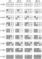
図2は、本実施形態の高画質モードにおけるドット配置パターン化処理で変換する、入力レベル0〜8に対する出力パターンを示している。図の左に示した各レベル値は、ハーフトーン処理部からの出力値であるレベル0〜レベル8に相当している。右側に配列した縦2エリア×横4エリアで構成される領域は、ハーフトーン処理で出力された1画素(ピクセル)の領域に対応するもので、縦横ともに600ppi(ピクセル/インチ;参考値)の画素密度に対応する大きさとなっている。また、1画素内の各エリアは、ドットのオン・オフが定義される最小単位に相当するもので、縦が1200dpi(ドット/インチ;参考値)、横が2400dpiの記録密度に対応するものである。本実施形態の記録装置では、上記記録密度に対応した、縦が約20μm、横が約10μmで表現される1つのエリアに対し、2plのインク滴が1つ記録されて所望の濃度が得られる様に設計されている。
FIG. 2 shows output patterns for
また、図2において、縦方向は記録ヘッドの吐出口が配列する方向であり、エリアの配列密度と吐出口の配列密度とが1200dpiという値で一致している。横方向は記録ヘッドの走査方向を示しており、本実施形態の高画質写真モードでは、記録ヘッドは2400dpiの密度で記録を行う構成となっている。 In FIG. 2, the vertical direction is the direction in which the ejection openings of the recording head are arranged, and the arrangement density of the areas and the arrangement density of the ejection openings coincide with each other at a value of 1200 dpi. The horizontal direction indicates the scanning direction of the recording head, and in the high-quality photo mode of this embodiment, the recording head is configured to perform recording at a density of 2400 dpi.
更に、図において、丸印を記入したエリアがドットの記録を行うエリアを示しており、レベル数が上がるに従って、記録するドット数も1つずつ増加している。 Furthermore, in the figure, the area in which a circle is entered indicates an area where dots are recorded, and the number of dots to be recorded increases by one as the number of levels increases.
(4n)〜(4n+3)は、nに1以上の整数を代入することにより、入力画像の左端からの横方向の画素位置を示している。また、その下に示した各パターンは、同一の入力レベルにおいても画素位置に応じて互いに異なる複数のパターンが用意されていることを示している。すなわち、同一のレベルが入力された場合にも、記録媒体上では(4n)〜(4n+3)に示した4種類のドット配置パターンが巡回されて割当てられる構成となっているのである。そして、このような構成にしておくことは、ドット配置パターンの上段に位置するノズルと下段に位置するノズルとで吐出回数を分散させたり、記録装置特有の様々なノイズを分散させたり、という様々な効果が得られるのである。 (4n) to (4n + 3) indicate pixel positions in the horizontal direction from the left end of the input image by substituting an integer of 1 or more for n. Each of the patterns shown below indicates that a plurality of different patterns are prepared according to the pixel position even at the same input level. That is, even when the same level is input, four types of dot arrangement patterns shown in (4n) to (4n + 3) are cyclically assigned on the recording medium. In addition, such a configuration has various effects such as distributing the number of ejections between the nozzles located in the upper stage and the nozzles located in the lower stage of the dot arrangement pattern and various noises peculiar to the printing apparatus. The effect is obtained.
本実施形態の高画質写真モードにおいては、最終的にこのような形でオリジナル画像の濃度情報が反映され、ドット配列パターン化処理を終了した段階で、記録媒体に対するドットの配列パターンが全て決定される。 In the high-quality photographic mode of the present embodiment, the density information of the original image is finally reflected in such a form, and when the dot arrangement patterning process is completed, all the dot arrangement patterns for the recording medium are determined. The
以下に高画質写真モードにおけるマスクデータ変換処理J0008について説明する。
上述したドット配置パターン化処理により、記録媒体上の各エリアに対するドットの有無は決定されたので、この情報をそのまま記録ヘッドの駆動回路に入力すれば、所望の画像を記録することは可能である。しかし、インクジェット記録装置においては、通常マルチパス記録という記録方法が採用されている。
The mask data conversion process J0008 in the high quality photo mode will be described below.
Since the dot arrangement patterning process described above determines the presence or absence of dots for each area on the recording medium, a desired image can be recorded by inputting this information directly into the drive circuit of the recording head. . However, in an ink jet recording apparatus, a recording method called multi-pass recording is usually employed.
以下にマルチパス記録方法について簡単に説明する。
図3は、マルチパス記録方法を説明するために、記録ヘッドおよび記録パターンを模式的に示したものである。P0001は記録ヘッドを示し、ここでは簡単のため16個のノズルを有するものとする。ノズルは、図のように第1〜第4の4つのノズル群に分割され、各ノズル群には4つずつのノズルが含まれている。P0002はマスクパターンを示し、各ノズルが記録を行うことが可能なエリア(記録可能箇所)を黒塗りで示している。各ノズル群が記録するパターンは互いに補完の関係にあり、これらを重ね合わせると4×4のエリアに対応した領域の記録が完成される構成となっている。
The multipass recording method will be briefly described below.
FIG. 3 schematically shows a recording head and a recording pattern for explaining the multipass recording method. P0001 indicates a recording head. Here, for simplicity, it is assumed that it has 16 nozzles. As shown in the drawing, the nozzles are divided into first to fourth nozzle groups, and each nozzle group includes four nozzles. P0002 indicates a mask pattern, and an area (recordable portion) where each nozzle can perform recording is indicated in black. The patterns recorded by each nozzle group are complementary to each other. When these patterns are overlapped, recording of a region corresponding to a 4 × 4 area is completed.
P0003〜P0006で示した各パターンは、記録走査を重ねていくことによって画像が完成されていく様子を示したものである。各記録走査が終了するたびに、記録媒体は図の矢印の方向にノズル群の幅分ずつ搬送される。よって、記録媒体の同一領域(各ノズル群の幅に対応する領域)は4回の記録走査によって初めて画像が完成される構成となっている。以上のように、記録媒体の各同一領域が複数回の走査で複数のノズル群によって形成されることは、ノズル特有のばらつきや記録媒体の搬送精度のばらつき等を低減させる効果がある。 Each pattern indicated by P0003 to P0006 shows a state in which an image is completed by overlapping recording scans. When each recording scan is completed, the recording medium is conveyed by the width of the nozzle group in the direction of the arrow in the figure. Therefore, the same area of the recording medium (area corresponding to the width of each nozzle group) is configured such that an image is completed only after four recording scans. As described above, the formation of each same area of the recording medium by a plurality of nozzle groups by a plurality of scans has an effect of reducing variations peculiar to the nozzles and variations in the conveyance accuracy of the recording medium.
図4は、本実施形態の高画質写真モードで実際に適用するマスクパターンを示したものである。本実施形態で適用する記録ヘッドH1001は768個のノズルを有している。また、高画質写真モードでは、図3と同様に4パスのマルチパスを行うものとする。従って、4つのノズル群にはそれぞれ192個ずつのノズルが属することになる。マスクパターンの大きさは、縦方向がノズル数と同等の768エリア、横方向は256エリアとなっており、4つのノズル群で互いに補完の関係を保つような構成となっている。 FIG. 4 shows a mask pattern actually applied in the high-quality photographic mode of this embodiment. A recording head H1001 applied in this embodiment has 768 nozzles. In the high-quality photo mode, it is assumed that 4-pass multi-pass is performed as in FIG. Accordingly, 192 nozzles belong to each of the four nozzle groups. The size of the mask pattern is such that the vertical direction is 768 areas equal to the number of nozzles and the horizontal direction is 256 areas, and the four nozzle groups maintain a complementary relationship with each other.
ところで、本実施形態で適用するような、多数の小液滴を高周波数で吐出するようなインクジェット記録ヘッドにおいては、記録動作時に記録部近傍に気流が生じ、この気流が特に記録ヘッドの端部に位置するノズルの吐出方向に影響を与えることが確認されている。よって、本実施形態の高画質モード用のマスクパターンにおいては、図4からも判るように、各ノズル群また同一のノズル群の中でも、領域によって記録可能比率の分布に偏りを持たせている。図4で示すように、端部のノズルの記録可能比率を中央部に対して低減した構成のマスクパターンを適用することにより、端部のノズルが吐出したインク滴の着弾位置ずれによる弊害を目立たなくすることが可能となるのである。 By the way, in an ink jet recording head that discharges a large number of small droplets at a high frequency as applied in the present embodiment, an air flow is generated in the vicinity of the recording unit during a recording operation, and this air flow is particularly generated at the end of the recording head. It has been confirmed that it affects the discharge direction of the nozzle located in the position. Therefore, in the mask pattern for the high image quality mode of this embodiment, as can be seen from FIG. 4, the distribution of the recordable ratio is biased depending on the region in each nozzle group or the same nozzle group. As shown in FIG. 4, by applying a mask pattern having a configuration in which the recordable ratio of the nozzles at the end is reduced with respect to the center, the adverse effect due to the landing position deviation of the ink droplets ejected by the nozzle at the end is conspicuous It is possible to eliminate it.
本実施形態においては、図4で示したマスクデータや、他の記録モードで適用する複数のマスクデータが記録装置本体内のメモリに格納してあり、マスクデータ変換処理においては、当該マスクデータと上述したドット配置パターン化処理の出力信号との間でAND処理をかけることにより、各記録走査で実際に吐出させる記録画素が決定され、出力信号として記録ヘッドH1001の駆動回路J0009に入力される。 In the present embodiment, the mask data shown in FIG. 4 and a plurality of mask data to be applied in other recording modes are stored in the memory in the recording apparatus main body. In the mask data conversion process, the mask data and By applying AND processing to the output signal of the dot arrangement patterning process described above, the recording pixels that are actually ejected in each recording scan are determined and input to the drive circuit J0009 of the recording head H1001 as an output signal.
駆動回路J0009に入力された各色の1bitデータは、記録J0010の駆動パルスに変換され、それぞれ記録ヘッドより所定のタイミングでインクが吐出される。 The 1-bit data of each color input to the driving circuit J0009 is converted into driving pulses for recording J0010, and ink is ejected from the recording head at a predetermined timing.
なお、記録装置における上述のドット配置パターン化処理やマスクデータ変換処理は、それらに専用のハードウエア回路を用い記録装置の制御部を構成するCPUの制御の下に実行されているものとする。 Note that the above-described dot arrangement patterning process and mask data conversion process in the printing apparatus are executed under the control of the CPU that constitutes the control unit of the printing apparatus using a dedicated hardware circuit.
次に、本実施形態における高速モードで記録する場合の処理を説明する。高速モードにおいても、図1で示した処理の流れによって説明することが可能であるが、本実施形態の高速モードにおいては、適用するインクをシアン、マゼンタ、イエローおよびブラックの基本の4色のみとし、処理時間の高速化を図っている。よって、後段処理J0003では、R、G、Bの8bitデータをC、M、Y、Kの8bitのデータに変換し、続く処理ではC、M、およびKの4色のデータについての処理を行うことになる。 Next, processing when recording in the high-speed mode in the present embodiment will be described. The high-speed mode can also be explained by the processing flow shown in FIG. 1, but in the high-speed mode of the present embodiment, only four basic colors of cyan, magenta, yellow, and black are applied. , To speed up the processing time. Therefore, in the post-processing J0003, the 8-bit data of R, G, and B is converted into 8-bit data of C, M, Y, and K, and the processing for the four color data of C, M, and K is performed in the subsequent processing. It will be.
また、ハーフトーニングJ0005においては、高画質写真モードと同様に、8ビットの色分解データを4ビットのデータに変換する量子化が行われる。但し本高速モードでは、誤差拡散法を用いずに、多値のディザパターンを用いて、256階調の8ビットデータを、5階調の4ビットデータに量子化変換している。すなわち、ドット配置のパターン化処理における配置パターンを示すためのインデックスデータは、高画質写真モードと同様に4ビットのデータとなるが、その内容は5階調分の情報となっている。 In the halftoning J0005, quantization is performed to convert 8-bit color separation data into 4-bit data, as in the high-quality photo mode. However, in this high-speed mode, 256-bit 8-bit data is quantized and converted to 5-gradation 4-bit data using a multi-value dither pattern without using the error diffusion method. That is, the index data for indicating the arrangement pattern in the dot arrangement patterning process is 4-bit data as in the high-quality photo mode, but the content is information for five gradations.
印刷データ作成処理J0006によって、上記4ビットのインデックスデータを内容とする印刷イメージ情報に印刷制御情報を加えた印刷データを作成するのは、上記高画質写真モードと同様である。 The print data creation process J0006 creates print data in which the print control information is added to the print image information containing the 4-bit index data as in the high-quality photo mode.
記録装置は、高画質写真モードの時と同様に、入力されてきた印刷データに対し、ドット配置パターン化処理J0007およびマスクデータ変換処理J0008を行う。 The recording apparatus performs a dot arrangement patterning process J0007 and a mask data conversion process J0008 on the input print data as in the high-quality photo mode.
以下に本実施形態の高速モードにおけるドット配置パターン化処理J0007について説明する。高速モードにおけるドット配置パターン化処理では、0〜4の多値レベルをドットの有無を決定する2値レベルまで低減する。具体的には、ハーフトーン処理部からの出力値であるレベル0〜4の4ビットデータで表現される画素ごとに、その画素の階調値(レベル0〜4)に対応したドット配置パターンを割当て、これにより1画素内の複数のエリア各々にドットのオン・オフを定義し、1画素内の各エリアに「1」または「0」の1ビットの吐出データを配置する。
The dot arrangement patterning process J0007 in the high speed mode of this embodiment will be described below. In the dot arrangement patterning process in the high-speed mode, the multi-value level of 0 to 4 is reduced to a binary level that determines the presence or absence of dots. Specifically, for each pixel represented by 4-bit data of
図5は、本実施形態の高速モードにおけるドット配置パターン化処理で変換する、入力レベル0〜4に対する出力パターンを示している。図の左に示した各レベル値は、ハーフトーン処理部からの出力値であるレベル0〜レベル4に相当している。右側に配列した縦2エリア×横2エリアで構成される各マトリクスの領域は、ハーフトーン処理で出力された1画素の領域に対応するものである。上述した高画質写真モードでは、ハーフトーニングで出力された600ppiの1画素(ピクセル)の領域に対し、縦が1200dpi(ドット/インチ;参考値)、横が2400dpiの記録密度でドットを記録する構成であった。これに対し、高速モードでは、600ppiの1画素領域に対し、縦2エリア×横2エリアで記録される構成となっている。
FIG. 5 shows output patterns for
また、高速モードにおいては、高画質写真モードで説明した図2に見るように、同一のレベルにおいて、複数種類のドット配置パターンが巡回されて割当てられるような構成とはなっていない。全てのレベルにおいて、対応されるドット配置パターンは1種類となっている。 In the high-speed mode, as shown in FIG. 2 described in the high-quality photo mode, a configuration in which a plurality of types of dot arrangement patterns are cyclically assigned at the same level is not provided. At all levels, the corresponding dot arrangement pattern is one type.
このように、本実施形態の高速モードでは、各パターンの領域が2エリア×2エリアと小さいこと、および巡回されるパターンが1種類に限定されることにより、高画質写真モードに比べて、ドット配置パターンを格納するためのメモリ領域を低く抑えることができている。 As described above, in the high-speed mode of the present embodiment, each pattern area is as small as 2 areas × 2 areas, and the pattern to be circulated is limited to one type. The memory area for storing the arrangement pattern can be kept low.
以下に本実施形態の高速モードにおけるマスクデータ変換処理J0008について説明する。
本実施形態の高速モードでは、3パスのマルチパス記録を行うものとする。
The mask data conversion process J0008 in the high speed mode of this embodiment will be described below.
In the high-speed mode of this embodiment, three-pass multipass printing is performed.
図6は、本実施形態の高速モードで実際に適用するマスクパターンを示したものである。本実施形態で適用する記録ヘッドH1001は768個のノズルを有しており、ここでは3パスのマルチパス記録を行うので、768個のノズルは、256個ずつの3つのノズル群に分割される。マスクパターンの大きさは、縦方向がノズル数と同等の768エリア、横方向は386エリアとなっている。本実施形態の高速モードにおいては、各ノズル群で平均50%ずつの記録がなされ、3つのノズル群を互いに重ね合わせて記録することにより、150%の記録が行われる構成となっている。 FIG. 6 shows a mask pattern actually applied in the high-speed mode of this embodiment. The recording head H1001 applied in the present embodiment has 768 nozzles, and here, since three-pass multipass printing is performed, the 768 nozzles are divided into three nozzle groups of 256 each. . The size of the mask pattern is 768 areas in the vertical direction equal to the number of nozzles, and 386 areas in the horizontal direction. In the high-speed mode of the present embodiment, 50% recording is performed on average for each nozzle group, and 150% recording is performed by recording the three nozzle groups superimposed on each other.
以下に、上記150%の記録を行うための目的および構成を詳細に説明する。上述したように本実施形態の高速モードでは、ハーフトーニングJ0005で出力された1画素で表現される領域に対し、図5で説明したドット配置パターン化処理では、4ドットまでしか記録されない構成となっている。しかし本実施形態の記録装置では、既に高画質写真モードで説明したように、2plの小ドロップを、1画素に対して8個まで記録されるように画像設計されている。よって、高速モードで、1画素に対して4個のまま記録を行ってしまうと、1画素に対するドット不足となり、結果的に不十分な濃度しか得られない画像となってしまう。本実施形態においては、この高速モードにおけるドット不足を、マスクデータ変換処理にて補うものとする。 The purpose and configuration for performing the above-mentioned 150% recording will be described in detail below. As described above, in the high-speed mode of the present embodiment, the dot arrangement patterning process described with reference to FIG. 5 can record only up to 4 dots for the area represented by one pixel output by halftoning J0005. ing. However, in the recording apparatus of this embodiment, as already described in the high-quality photo mode, the image is designed so that up to eight small 2 pl drops are recorded per pixel. Therefore, if recording is performed with four pixels per pixel in the high-speed mode, dots are insufficient for one pixel, resulting in an image with only insufficient density. In the present embodiment, the shortage of dots in the high-speed mode is compensated by mask data conversion processing.
図7は、図6のマスクパターンにおける各ノズル群に対応する領域の、左上に位置する4エリア×4エリアの領域P0007〜P0009を拡大して示したものである。これら3つの領域は、記録媒体上で重ね合わせられて記録され、P0010はP0007〜P0009のパターンを重ねた結果を示している。P0007〜P0009において、白丸で示した部分は、その記録走査で2plのインク滴を記録するエリアを示している。また、P0010においては、白丸で示した部分は、2plのドットが1つ記録されるエリア、黒丸で示した部分は、2plのドットが2つ、すなわち合計で4plのインク滴が記録されるエリアを示している。P0010に見るように、黒丸と白丸は、互い違いのエリアに位置するようになっており、結果的に、1画素領域すなわち2エリア×2エリアに対するドットの配置は全て相似形で、最高6ドットまでインク滴が記録されることになる。 FIG. 7 is an enlarged view of the areas P0007 to P0009 of 4 areas × 4 areas located in the upper left of the area corresponding to each nozzle group in the mask pattern of FIG. These three regions are recorded by being superimposed on the recording medium, and P0010 indicates a result of overlapping the patterns of P0007 to P0009. In P0007 to P0009, a portion indicated by a white circle indicates an area where a 2 pl ink droplet is recorded by the recording scan. In P0010, a white circle indicates an area where one 2 pl dot is recorded, and a black circle indicates an area where two 2 pl dots are recorded, that is, a total of 4 pl ink droplets are recorded. Is shown. As seen in P0010, black circles and white circles are located in staggered areas, and as a result, the arrangement of dots for one pixel area, that is, 2 areas × 2 areas is all similar, with a maximum of 6 dots Ink drops will be recorded.
図8は、図5で示した入力レベル0〜4に対して、結果的に記録されるドットの様子および数を示したものである。図において、白丸は2plのインク滴が1つ記録されるエリアを、黒丸は2plのインク滴が2つ記録されるエリアを、さらに空白はインク滴が記録されないエリアをそれぞれ示している。図に見るように、レベル0〜レベル2までは、レベルが1つ上がると新たに1ドット付加されるように構成されているが、レベル3およびレベル4においては1レベルにつき新たに2ドットずつが付加されている。一般に、インクジェット記録装置においては、階調が低い領域では粒状感が問題視されるのでドットの強調は極力回避したい。また、階調が高い状態では1ドット程度を追加しても濃度は上がりにくく、その一方で最高濃度はなるべく高く設定することが望まれる。よって、本実施形態では、高濃度に行くほど追加されるドット数を多く設定し、最終的には、1画素に6ドットが記録されるような構成とした。
FIG. 8 shows the state and number of dots recorded as a result for the
但し、このドット数は、本発明を限定するものではない。低いレベルから2つずつドットを追加する形態にしてもよく、さらに最終的な記録ドット数が6ドット以上であってもよい。本来、高画質写真モードと最高濃度の記録ドット数を揃えるならば、レベル4では8ドット記録することが望まれる。しかし一般に、高画質写真モードのような画質を重視するモードにおいては、光沢がありインクの受容量も大きな記録媒体が用いられることが多い一方で、図表やテキストのような文書を記録する高速モードの場合には、普通紙のようなインク受容量のあまり多くない記録媒体に記録することが多い。よって、本実施形態の高速モードにおいては、高画質写真モードほど多くのインクを記録しない構成としている。
However, this number of dots does not limit the present invention. Two dots may be added from the lower level, and the final number of recorded dots may be 6 dots or more. Originally, it is desirable to record 8 dots at
どのようなドット数に定めるにせよ、ドット配置パターン化処理で定められたエリアの数以上(あるいは以下)のドットを記録し、かつドット配置パターン化処理における各レベルに対応する記録ドット数が一義的に決定可能であれば、本発明の効果は得られるものである。この様にすることで、各入力レベルに対して、出力パターンを1対1に対応させつつも、各レベルでは好適な状態で強調ドットが付加されたドットパターン配列を得ることが可能となる。逆に言えば、図8のような強調されたドットパターン配列で出力されることを前提として、それ以前の処理(すなわち前段処理からハーフトー二ングまで)を行うことができるのである。 Regardless of the number of dots, the number of dots that are equal to or greater than (or less than) the number of areas defined in the dot arrangement patterning process is recorded, and the number of recording dots corresponding to each level in the dot arrangement patterning process is unique. If it can be determined automatically, the effect of the present invention can be obtained. In this way, it is possible to obtain a dot pattern array in which emphasis dots are added in a suitable state at each level while making the output pattern correspond to each input level on a one-to-one basis. In other words, on the premise that the dot pattern array is emphasized as shown in FIG. 8, the previous processing (that is, from the previous processing to the half toning) can be performed.
再び、図1を参照するに、マスクデータ変換処理J008での処理が施された1ビットのデータは、記録ヘッドの駆動回路J009に送られる。そして、さらに記録ヘッドJ0010の駆動パルスに変換され、それぞれ記録ヘッドより所定のタイミングでインクが吐出される。 Referring again to FIG. 1, the 1-bit data that has been subjected to the mask data conversion process J008 is sent to the printhead drive circuit J009. Further, it is converted into a drive pulse for the recording head J0010, and ink is ejected from the recording head at a predetermined timing.
以上説明したように、本実施形態によれば、2plという少量のインク滴によって所望の濃度が達成されるような記録密度が設定されたインクジェット記録装置において、より低い記録密度で画像を記録する高速モードを設けながらも、所望の記録濃度が得られるような、マスクデータ変換処理を設けている。そして、このようなマスクパターンによって出力された画像においては、ハーフトーン後の1画素の階調レベルに対しても、所望の線形性が保たれていることが特徴とされるのである。 As described above, according to the present embodiment, in an ink jet recording apparatus in which a recording density is set such that a desired density is achieved with a small amount of ink droplets of 2 pl, a high speed for recording an image at a lower recording density. A mask data conversion process is provided so as to obtain a desired recording density while providing a mode. The image output by such a mask pattern is characterized in that the desired linearity is maintained even with respect to the gradation level of one pixel after halftone.
(インクジェット装置の機構部の概略構成)
ここで、本実施形態で適用するインクジェット記録装置の機構部の概略構成を説明する。本実施形態における記録装置本体は、各機構の役割から、給紙部、用紙搬送部、キャリッジ部、排紙部、クリーニング部およびこれらを保護し、意匠性を持たす外装部から構成されている。以下、これらの概略を説明していく。
(Schematic structure of the mechanism part of the inkjet device)
Here, a schematic configuration of the mechanism unit of the ink jet recording apparatus applied in the present embodiment will be described. The main body of the recording apparatus according to the present embodiment includes a paper feed unit, a paper transport unit, a carriage unit, a paper discharge unit, a cleaning unit, and an exterior unit that protects them and has design properties from the role of each mechanism. The outline of these will be described below.
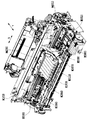
図11は、記録装置の斜視図である。また、図12および図13は、記録装置本体の内部機構を説明するための図であり、図12は右上部からの斜視図、図13は記録装置本体の側断面図をそれぞれ示したものである。 FIG. 11 is a perspective view of the recording apparatus. 12 and 13 are diagrams for explaining the internal mechanism of the recording apparatus main body. FIG. 12 is a perspective view from the upper right portion, and FIG. 13 is a side sectional view of the recording apparatus main body. is there.
記録装置において給紙を行う際には、まず給紙トレイM2060を含む給紙部において記録媒体の所定枚数のみが給紙ローラM2080と分離ローラM2041から構成されるニップ部に送られる。送られた記録媒体はニップ部で分離され、最上位の記録媒体のみが用紙搬送部に搬送される。用紙搬送部に送られた記録媒体は、ピンチローラホルダM3000及びペーパーガイドフラッパーM3030に案内されて、搬送ローラM3060とピンチローラM3070とのローラ対に送られる。搬送ローラM3060とピンチローラM3070とからなるローラ対は、LFモータE0002の駆動により回転され、この回転により記録媒体がプラテンM3040上を搬送される。 When paper feeding is performed in the recording apparatus, first, only a predetermined number of recording media are fed to a nip portion including a paper feed roller M2080 and a separation roller M2041 in a paper feed unit including a paper feed tray M2060. The sent recording medium is separated at the nip portion, and only the uppermost recording medium is conveyed to the sheet conveying portion. The recording medium sent to the paper transport unit is guided by the pinch roller holder M3000 and the paper guide flapper M3030, and is sent to the roller pair of the transport roller M3060 and the pinch roller M3070. A roller pair composed of a conveyance roller M3060 and a pinch roller M3070 is rotated by driving of the LF motor E0002, and the recording medium is conveyed on the platen M3040 by this rotation.
キャリッジ部は、記録ヘッドH1001を取り付けるためのキャリッジM4000を有しており、キャリッジM4000は、ガイドシャフトM4020およびガイドレールによって支持されている。ガイドシャフトM4020は、シャーシM1010に取り付けられており、記録媒体の搬送方向に対して直角方向にキャリッジM4000を往復走査させるように案内支持している。また、キャリッジM4000は、シャーシM1010に取り付けられたキャリッジモータE0001によりタイミングベルトM4041を介して駆動される。更に、キャリッジM4000には、電気基板E0014から記録ヘッドH1001へ、駆動信号を伝えるための不図示のフレキシブルケーブルが接続されている。このような構成において記録媒体に画像形成する場合、搬送方向(カラム方向)に対しては、搬送ローラM3060およびピンチローラM3070からなるローラ対が、記録媒体を搬送して位置決めする。また、走査方向(ラスタ方向)に対しては、キャリッジモータE0001によりキャリッジM4000を上記搬送方向と垂直な方向に移動させて、記録ヘッドH1001(図14)を目的の画像形成位置に配置させる。位置決めされた記録ヘッドH1001は、電気基板E0014からの信号に従って、記録媒体に対しインクを吐出する。記録ヘッドH1001についての詳細な構成は後述するが、本実施形態の記録装置においては、記録ヘッドH1001により記録を行いながらキャリッジM4000が走査する記録主走査と、搬送ローラM3060により記録媒体が搬送される副走査とを交互に繰り返すことにより、記録媒体上に画像を形成していく構成となっている。 The carriage unit includes a carriage M4000 for mounting the recording head H1001, and the carriage M4000 is supported by a guide shaft M4020 and a guide rail. The guide shaft M4020 is attached to the chassis M1010 and guides and supports the carriage M4000 to reciprocate in a direction perpendicular to the recording medium conveyance direction. The carriage M4000 is driven via a timing belt M4041 by a carriage motor E0001 attached to the chassis M1010. Further, a flexible cable (not shown) for transmitting a drive signal from the electric board E0014 to the recording head H1001 is connected to the carriage M4000. When an image is formed on a recording medium in such a configuration, a pair of rollers including a conveyance roller M3060 and a pinch roller M3070 conveys and positions the recording medium in the conveyance direction (column direction). Also, with respect to the scanning direction (raster direction), the carriage M4000 is moved in a direction perpendicular to the transport direction by the carriage motor E0001, and the recording head H1001 (FIG. 14) is arranged at a target image forming position. The positioned recording head H1001 ejects ink to the recording medium in accordance with a signal from the electric substrate E0014. Although a detailed configuration of the recording head H1001 will be described later, in the recording apparatus according to the present embodiment, a recording medium is scanned by the carriage M4000 while recording is performed by the recording head H1001, and a recording medium is conveyed by the conveying roller M3060. An image is formed on a recording medium by alternately repeating sub-scanning.
最後に画像形成された記録媒体は、排紙部で第1の排紙ローラM3110と拍車M3120とのニップに挟まれ、搬送されて排紙トレイM3160に排出される。 The recording medium on which the image has been finally formed is sandwiched between nips of the first paper discharge roller M3110 and the spur M3120 at the paper discharge unit, conveyed, and discharged to the paper discharge tray M3160.
なお、クリーニング部において、画像記録前後の記録ヘッドH1001をクリーニングする目的のために、キャップM5010を記録ヘッドH1001のインク吐出口に密着させた状態で、ポンプM5000を作用させると、記録ヘッドH1001から不要なインク等が吸引されるようになっている。また、キャップM5010を開けた状態で、キャップM5010に残っているインクを吸引することにより、残インクによる固着およびその後の弊害が起こらないように配慮されている。 In the cleaning unit, for the purpose of cleaning the recording head H1001 before and after image recording, if the pump M5000 is operated with the cap M5010 in close contact with the ink discharge port of the recording head H1001, it is unnecessary from the recording head H1001. Ink or the like is sucked. Further, by sucking the ink remaining in the cap M5010 with the cap M5010 opened, consideration is given to preventing the remaining ink from sticking and the subsequent adverse effects.
(記録ヘッド構成)
以下に上記実施形態で適用できるヘッドカートリッジH1000の構成について説明する。ヘッドカートリッジH1000は、記録ヘッドH1001と、インクタンクH1900を搭載する手段、およびインクタンクH1900から記録ヘッドにインクを供給するための手段を有しており、キャリッジM4000に対して着脱可能に搭載される。
(Recording head configuration)
The configuration of the head cartridge H1000 that can be applied in the above embodiment will be described below. The head cartridge H1000 has a recording head H1001, means for mounting the ink tank H1900, and means for supplying ink from the ink tank H1900 to the recording head, and is detachably mounted on the carriage M4000. .
図14は、本実施形態で適用可能なヘッドカートリッジH1000に対し、インクタンクH1900を装着する様子を示した図である。記録装置は、シアン、ライトシアン、マゼンタ、ライトマゼンタ、イエロー、ブラックおよびレッドの7色のインクによって画像を形成するため、インクタンクH1900も7色分が独立に用意されている。そして、図に示すように、それぞれがヘッドカートリッジH1000に対して着脱自在となっている。尚、インクタンクH1900の着脱は、キャリッジM4000にヘッドカートリッジH1000が搭載された状態で行えるようになっている。 FIG. 14 is a diagram illustrating a state in which the ink tank H1900 is attached to the head cartridge H1000 applicable in the present embodiment. Since the recording apparatus forms an image with seven colors of ink of cyan, light cyan, magenta, light magenta, yellow, black and red, the ink tank H1900 is also prepared for seven colors independently. As shown in the figure, each is detachable from the head cartridge H1000. The ink tank H1900 can be attached and detached while the head cartridge H1000 is mounted on the carriage M4000.
図15は、ヘッドカートリッジH1000の分解斜視図を示したものである。図において、ヘッドカートリッジH1000は、第1の記録素子基板H4700および第2の記録素子基板H4701、第1のプレートH1200、第2のプレートH1400、電気配線基板H1300、タンクホルダーH1500、流路形成部材H1600、フィルターH1700、シールゴムH1800などから構成されている。 FIG. 15 is an exploded perspective view of the head cartridge H1000. In the figure, a head cartridge H1000 includes a first recording element substrate H4700 and a second recording element substrate H4701, a first plate H1200, a second plate H1400, an electric wiring substrate H1300, a tank holder H1500, and a flow path forming member H1600. , Filter H1700, seal rubber H1800, and the like.
第1の記録素子基板H4700および第2の記録素子基板H4701はSi基板であり、その片面にインクを吐出するための複数の記録素子(ノズル)がフォトリソ技術により形成されている。各記録素子に電力を供給するAl等の電気配線は、成膜技術により形成されており、個々の記録素子に対応した複数のインク流路もまた、フォトリソグラフィ技術により形成されている。さらに、複数のインク流路にインクを供給するためのインク供給口が裏面に開口するように形成されている。 The first recording element substrate H4700 and the second recording element substrate H4701 are Si substrates, and a plurality of recording elements (nozzles) for ejecting ink are formed on one side thereof by a photolithography technique. Electric wiring such as Al for supplying electric power to each recording element is formed by a film forming technique, and a plurality of ink flow paths corresponding to individual recording elements are also formed by a photolithography technique. Further, an ink supply port for supplying ink to the plurality of ink flow paths is formed to open on the back surface.
図16は、第1の記録素子基板H4700および第2の記録素子基板H4701の構成を説明するための正面拡大図である。H4000〜H4600は、それぞれ異なるインク色に対応するノズル列であり、第1の記録素子基板H4700には、ライトマゼンタの供給されるノズル列H4000、レッドインクの供給されるノズル列H4100、ブラックインクの供給されるノズル列H4200、およびライトシアンインクの供給されるノズル列H4300の4色分のノズル列が構成されている。また、第2の記録素子基板H4701には、シアンインクの供給されるノズル列H4400、マゼンタインクの供給されるノズル列H4500、およびイエローインクの供給されるノズル列H4600の3色分のノズル列が形成されている。 FIG. 16 is an enlarged front view for explaining the configuration of the first recording element substrate H4700 and the second recording element substrate H4701. H4000 to H4600 are nozzle rows corresponding to different ink colors, and the first printing element substrate H4700 has a nozzle row H4000 supplied with light magenta, a nozzle row H4100 supplied with red ink, and a black ink supply. There are configured nozzle rows for four colors, a nozzle row H4200 to be supplied and a nozzle row H4300 to which light cyan ink is supplied. In addition, the second printing element substrate H4701 has nozzle rows for three colors: a nozzle row H4400 to which cyan ink is supplied, a nozzle row H4500 to which magenta ink is supplied, and a nozzle row H4600 to which yellow ink is supplied. Is formed.
各ノズル列は、記録媒体の搬送方向に1200dpi(dot/inch;参考値)の間隔で並ぶ768個のノズルによって構成され、約2ピコリットルのインク滴を吐出させる。各ノズル吐出口における開口面積は、およそ100平方μm2に設定されている。また、第1の記録素子基板H4700および第2の記録素子基板H4701は、再び図15を参照するに、第1のプレートH1200に接着固定されており、ここには、第1の記録素子基板H4700および第2の記録素子基板H4701にインクを供給するためのインク供給口H1201が形成されている。 Each nozzle row is composed of 768 nozzles arranged at an interval of 1200 dpi (dot / inch; reference value) in the conveyance direction of the recording medium, and ejects approximately 2 picoliters of ink droplets. The opening area at each nozzle outlet is set to approximately 100 square μm 2 . Further, referring to FIG. 15 again, the first recording element substrate H4700 and the second recording element substrate H4701 are bonded and fixed to the first plate H1200. Here, the first recording element substrate H4700 is fixed. In addition, an ink supply port H1201 for supplying ink to the second recording element substrate H4701 is formed.
さらに、第1のプレートH1200には、開口部を有する第2のプレートH1400が接着固定されており、この第2のプレートH1400は、電気配線基板H1300と第1の記録素子基板H4700および第2の記録素子基板H4701とが電気的に接続されるように、電気配線基板H1300を保持している。 Further, a second plate H1400 having an opening is bonded and fixed to the first plate H1200. The second plate H1400 is composed of an electric wiring substrate H1300, a first recording element substrate H4700, and a second recording element substrate H4700. The electric wiring substrate H1300 is held so as to be electrically connected to the recording element substrate H4701.
電気配線基板H1300は、第1の記録素子基板H4700および第2の記録素子基板H4701に形成されている各ノズルからインクを吐出するための電気信号を印加するものであり、第1の記録素子基板H4700および第2の記録素子基板H4701に対応する電気配線と、この電気配線端部に位置し記録装置本体からの電気信号を受け取るための外部信号入力端子H1301とを有している。外部信号入力端子H1301は、タンクホルダーH1500の背面側に位置決め固定されている。 The electrical wiring substrate H1300 applies an electrical signal for ejecting ink from each nozzle formed on the first recording element substrate H4700 and the second recording element substrate H4701, and the first recording element substrate Electrical wiring corresponding to the H4700 and the second recording element substrate H4701 and an external signal input terminal H1301 for receiving an electrical signal from the recording apparatus main body located at the end of the electrical wiring. The external signal input terminal H1301 is positioned and fixed on the back side of the tank holder H1500.
一方、インクタンクH1900を保持するタンクホルダーH1500には、流路形成部材H1600が例えば超音波溶着により固定され、インクタンクH1900から第1のプレートH1200に通じるインク流路H1501を形成している。 On the other hand, in a tank holder H1500 that holds the ink tank H1900, a flow path forming member H1600 is fixed by, for example, ultrasonic welding to form an ink flow path H1501 that communicates from the ink tank H1900 to the first plate H1200.
インクタンクH1900と係合するインク流路H1501のインクタンク側端部には、フィルターH1700が設けられており、外部からの塵埃の侵入を防止し得るようになっている。また、インクタンクH1900との係合部にはシールゴムH1800が装着され、係合部からのインクの蒸発を防止し得るようになっている。 A filter H1700 is provided at the ink tank side end of the ink flow path H1501 that engages with the ink tank H1900, and can prevent dust from entering from the outside. Further, a seal rubber H1800 is attached to the engaging portion with the ink tank H1900 so that ink can be prevented from evaporating from the engaging portion.
さらに、前述のようにタンクホルダーH1500、流路形成部材H1600、フィルターH1700及びシールゴムH1800から構成されるタンクホルダー部と、第1の記録素子基板H4700および第2の記録素子基板H4701、第1のプレートH1200、電気配線基板H1300及び第2のプレートH1400から構成される記録ヘッド部H1001とを、接着等で結合することにより、ヘッドカートリッジH1000が構成されている。 Further, as described above, the tank holder portion composed of the tank holder H1500, the flow path forming member H1600, the filter H1700 and the seal rubber H1800, the first recording element substrate H4700, the second recording element substrate H4701, and the first plate. The head cartridge H1000 is configured by bonding the recording head unit H1001 including the H1200, the electric wiring substrate H1300, and the second plate H1400 by bonding or the like.
(第2の実施形態)
次に、本発明の第2の実施形態を説明する。上述した第1の実施形態では、高画質写真モードの記録密度に対し、より低い記録密度のモードを高速モードとして設定していた。これに対し、本実施形態においては、より小さなインク滴を用いながらも、第1実施形態と同様の記録密度で高画質写真モードを実現しようとしたものである。
(Second Embodiment)
Next, a second embodiment of the present invention will be described. In the first embodiment described above, a mode with a lower recording density is set as a high-speed mode with respect to a recording density in the high-quality photo mode. On the other hand, in the present embodiment, an attempt is made to realize a high-quality photo mode with a recording density similar to that of the first embodiment while using smaller ink droplets.
本実施形態においても、図1を用いて説明した画像データ変換処理の流れが適用できるものとする。但し、本実施形態で適用するインクジェット記録装置は、シアン、マゼンタ、イエロー、ブラックの4色のみで記録を行い、レッド、ライトシアンおよびライトマゼンタは適用しないものとする。よって、後段処理J0003では、R、G、Bの8bitデータをC、M、Y、Kの8bitのデータに変換し、続く処理ではC、M、YおよびKの4色のデータについての処理を行うことになる。 Also in this embodiment, it is assumed that the flow of the image data conversion process described with reference to FIG. 1 can be applied. However, the inkjet recording apparatus applied in this embodiment performs recording with only four colors of cyan, magenta, yellow, and black, and does not apply red, light cyan, and light magenta. Therefore, in the post-processing J0003, R, G, B 8-bit data is converted into C, M, Y, K 8-bit data, and the subsequent processing is performed on C, M, Y, and K color data. Will do.
また、ハーフトーニングJ0005においては、高画質写真モードと同様に、8ビットの色分解データを4ビットのデータに変換する量子化を多値誤差拡散法によって行い、256階調を9階調に変換するものとする。 Also, in the halftoning J0005, as in the high-quality photographic mode, quantization that converts 8-bit color separation data into 4-bit data is performed by the multi-value error diffusion method, and 256 gradations are converted to 9 gradations. It shall be.
但し、本実施形態で適用する記録ヘッドJ0010は、1pl程度のインク滴を吐出するものとし、吐出量すなわち記録媒体上でのドットの大きさを小さく設定することにより、低デューティーにおける粒状感を第1の実施形態よりも更に目立たなくしている。 However, the recording head J0010 applied in the present embodiment discharges about 1 pl of ink droplets, and by setting the discharge amount, that is, the size of the dots on the recording medium, to reduce the graininess at low duty. It is less noticeable than in the first embodiment.
このように、ドットを小さくした状態で、第1の実施形態の高画質写真モードと同様な記録を行なってしまうと、インクの打ち込み量が不足して濃度不足が懸念される。この様な場合、従来の方法に従えば、記録されるドットの大きさに応じて記録密度を高く設定することになる。しかしながら、記録装置において記録解像度をより高く設定することは、記録位置精度や記録媒体の搬送精度の向上、さらにはドット配置パターン化処理を始めとするデータ処理の大容量化が要され、より大掛かりな構成になってしまう。これに対し、市場で求められる写真画質においては、粒状感がある程度解消され、所定の階調性および濃度が確保されれば、記録解像度の大きさは、然程重視されていない。よって、本実施形態においては、粒状感を低減するためにインク滴を1plとより少量化しておきながらも、記録密度や記録精度を上げずに第1の実施形態と同様の記録装置を用いて、高品位写真モードを実現しようとしたものである。 As described above, if recording is performed in the same manner as in the high-quality photographic mode of the first embodiment in a state where the dots are small, there is a concern that the ink ejection amount is insufficient and the density is insufficient. In such a case, according to the conventional method, the recording density is set high according to the size of the dots to be recorded. However, setting a higher recording resolution in the recording apparatus requires an improvement in recording position accuracy and recording medium conveyance accuracy, and further increases in the capacity of data processing such as dot arrangement patterning processing. It will be a composition. On the other hand, in the photographic image quality required in the market, if the graininess is eliminated to some extent and predetermined gradation and density are ensured, the size of the recording resolution is not so important. Therefore, in the present embodiment, a recording apparatus similar to that of the first embodiment is used without increasing the recording density and recording accuracy while reducing the amount of ink droplets to 1 pl in order to reduce graininess. This is an attempt to realize a high-quality photo mode.
本実施形態の高画質写真モードにおいても、ドット配置パターン化処理J0007は図P1で示したものと同様のものを用いることができる。すなわち、ハーフトーン処理で9値として出力された、縦横ともに600ppiの1画素(ピクセル)の領域に対し、縦1200dpi×横2400dpiの記録密度で1plのインク滴を記録するのである。 Also in the high-quality photographic mode of this embodiment, the dot arrangement patterning process J0007 can be the same as that shown in FIG. That is, 1 pl of ink droplets is recorded at a recording density of 1200 dpi × 2400 dpi in the horizontal and vertical directions of 1 pixel (pixel), which is output as 9 values in halftone processing.
本実施形態の高画質写真モードにおいては、4パスのマルチパス記録を行なうものとする。ここでは、特にこの場合に適用するマスクパターンは図示していないが、図4と同様に、全768ノズルが192ノズルずつの4つのノズル群に分割されたマスクパターンとなっている。ただし、本実施形態で適用するマスクでは、4つのノズル群により形成される領域はそれぞれ50%デューティーずつの記録を行い、これらを重ね合わせることによって最終的に200%の記録を行う構成としている。 In the high-quality photographic mode of this embodiment, 4-pass multi-pass printing is performed. Here, although the mask pattern applied in this case is not shown in particular, as in FIG. 4, all 768 nozzles are divided into four nozzle groups of 192 nozzles. However, the mask applied in the present embodiment is configured such that the area formed by the four nozzle groups performs recording with 50% duty, and finally superimposes these to perform 200% recording.
図9は、上述した4パスのマスクパターンにおいて、それぞれのノズル群が記録するパターンの左上に位置する2エリア×4エリアを、図7と同様に示したものである。これら4つの領域P0081〜P0084は、記録媒体上で重ね合わせられて、結果としてP0085のようになっている。P0081〜P0084において、白丸で示した部分は、その記録走査で1plのインク滴を記録するエリアを示している。また、P0085においては、白丸で示した部分は1plのドットが1つ記録されるエリア、2重丸で示した部分は1plのドットが2つ、すなわち2plのインクが記録されるエリアを示している。さらに黒丸で示した部分は、1plのドットが3つ、すなわち3plのインクが記録されるエリアを示している。黒丸、2重丸および白丸の配列は、P0085に見るように、1画素領域すなわち2エリア×4エリアに対する領域には、最高16ドットまでインク滴が記録されるようになっている。
FIG. 9
更に、図2と同様に図9においても(4n)〜(4n+3)として示したように、画素の位置に応じて周期的に異なる複数のパターンの配列にも対応しており、結果的には2×4のエリアを、ハーフトーニングより出力された階調を表現するための1画素の領域として扱うことが可能となっている。 Further, as shown in FIG. 9, as shown in FIG. 9 as (4n) to (4n + 3), it corresponds to the arrangement of a plurality of patterns that differ periodically depending on the position of the pixel. A 2 × 4 area can be handled as a one-pixel area for expressing the gradation output from halftoning.
図10は、図9で示した入力レベル0〜8に対して、最終的に記録されるドットの様子および1画素領域に記録されるドット数を示したものである。図において、白丸は1plのインク滴が1つ記録されるエリアを、2重丸は1plのインク滴が2つ記録されるエリアを、黒丸は1plのインク滴が3つ記録されるエリアを、さらに空白はインク滴が記録されないエリアをそれぞれ示している。図に見るように、レベル0〜レベル2までは、レベルが1つ上がると、新たに1ドット付加されるように構成されているが、レベル3〜レベル6においては1レベルにつき、新たに2ドットずつが、さらにレベル7およびレベル8においては1レベルにつき、新たに3ドットずつ付加されている。
FIG. 10 shows how dots are finally recorded and the number of dots recorded in one pixel area with respect to the
第1の実施形態でも述べたように、インクジェット記録装置においては、階調が低い領域では粒状感が問題視されるのでドットの強調は極力回避したい。また、階調が高くなるにつれ1ドット程度を追加しても濃度は上がりにくく、その一方で最高濃度はなるべく高く設定することが望まれる。よって、本実施形態においても、高濃度に行くほど追加されるドット数が多く設定し、最終的には、1画素に16ドットが記録されるような構成とした。ただし、この構成は本実施形態を限定するものではない。ハーフトーニングより出力された階調数に応じて、線形的に1画素領域内に記録されるドット数が増加していれば、1画素領域内の記録ドットがどのような配列でいくつ記録されても本発明および本実施形態は有効となる。 As described in the first embodiment, in the ink jet recording apparatus, it is desired to avoid dot emphasis as much as possible because graininess is a problem in a low gradation region. Further, as the gradation becomes higher, the density is hardly increased even if about one dot is added, while the highest density is desired to be set as high as possible. Therefore, in this embodiment as well, the number of dots added is increased as the density is increased, and finally, 16 dots are recorded in one pixel. However, this configuration does not limit the present embodiment. If the number of dots recorded in one pixel area increases linearly according to the number of gradations output from halftoning, how many recording dots in one pixel area are recorded in what arrangement. In addition, the present invention and this embodiment are effective.
第1実施形態と同様、マスクデータ変換処理J0008での処理が施された1ビットのデータは、記録ヘッドの駆動回路J0009に送られる。そして、さらに記録ヘッドJ0010の駆動パルスに変換され、それぞれ記録ヘッドより所定のタイミングでインクが吐出される。 As in the first embodiment, the 1-bit data that has been subjected to the mask data conversion process J0008 is sent to the printhead drive circuit J0009. Further, it is converted into a drive pulse for the recording head J0010, and ink is ejected from the recording head at a predetermined timing.
以上説明したように、本実施形態によれば、第1実施形態で説明したような、2plのインク滴によって所望の濃度が達成されるような記録密度が設定されたインクジェット記録装置において、あえて吐出量を1plに低減し、ライトシアンやライトマゼンタのようなインクを用いずに低デューティーの粒状感を低減することができる。その一方で、吐出量を1plに低減した分を補足する形で、図9で示したようなドット配置パターンに対応したマスクパターンを用意することにより、1画素の階調レベルに対しても好適な線形性を保ちつつ、最終的には第1実施形態の高画質写真モードと同等の16plを1画素領域に記録することが可能となる。そして結果的には、第1実施形態よりも少ないデータ処理によって、写真画質に求められる高画質な画像を得ることが可能となるのである。 As described above, according to this embodiment, in the ink jet recording apparatus in which the recording density is set such that a desired density is achieved by 2 pl ink droplets as described in the first embodiment, ejection is intentionally performed. The amount can be reduced to 1 pl, and low-duty granularity can be reduced without using inks such as light cyan and light magenta. On the other hand, by preparing a mask pattern corresponding to the dot arrangement pattern as shown in FIG. 9 in a form supplementing the amount of discharge reduced to 1 pl, it is also suitable for the gradation level of one pixel. It is possible to finally record 16 pl equivalent to the high-quality photographic mode of the first embodiment in one pixel area while maintaining such linearity. As a result, it is possible to obtain a high-quality image required for photographic image quality with less data processing than in the first embodiment.
この様な構成は、上述したような吐出量を変調することが困難な記録ヘッドにおいて、あたかも1plから16plまでの変調が可能な記録ヘッドを用いて記録した場合と同等の効果が得られると同時に、16plの記録については複数の記録走査によって異なるノズルで少しずつインクが記録されていくので、より良好な画像を得ることが可能となる。実際、吐出量を変調可能な記録ヘッドは、その構成から、本実施形態のように高密度に記録素子を配列させて構成することは難しい。よって本発明のように、高密度に配列された記録ヘッドによって、あたかも吐出量が変調可能であるような記録が実現できることは、記録速度においても画像品位においても、より好ましいものと言えるのである。 Such a configuration can achieve the same effect as when recording is performed using a recording head capable of modulating from 1 pl to 16 pl in the recording head in which it is difficult to modulate the ejection amount as described above. In the case of 16 pl recording, ink is recorded little by little by different nozzles by a plurality of recording scans, so that a better image can be obtained. Actually, it is difficult to configure a recording head capable of modulating the ejection amount by arranging recording elements at a high density as in the present embodiment. Therefore, it can be said that it is more preferable in terms of the recording speed and the image quality that the recording head arranged in a high density as in the present invention can realize the recording in which the ejection amount can be modulated.
尚、以上で説明してきた本発明で適用したマスクパターンは、上述した実施形態で示したものに限定されるものではない。本発明の効果は、複数の記録走査によって記録される1画素あたりのドット記録数が、ハーフトーニングによって得られた階調レベルに応じた所定値になっていれば有効なのであり、各記録走査における個々の記録位置の配列はどのような形態であってもよい。 The mask pattern applied in the present invention described above is not limited to that shown in the above-described embodiment. The effect of the present invention is effective when the number of dots recorded per pixel recorded by a plurality of recording scans is a predetermined value corresponding to the gradation level obtained by halftoning. The arrangement of the individual recording positions may be any form.
尚、入力されたデータに対し、マルチパス用のマスクパターンを用い、同一のエリアに強調記録を行う技術は例えば特許文献3にもすでに開示されている。しかし、特許文献3に代表される従来の強調方法は、2値化後のドット配列に対し、マスクパターンによって無作為に強調するドットが決定されるものであった。すなわち、本実施形態の記録装置のように、ハーフトーニングによって多値の階調データを得た後、更にドット配置パターン化処理によって適切な階調を表現する構成においては、1画素領域内のドット配列とは全く無関係に強調が行われてしまうので、1画素に与えられた多値の階調データに意味がなくなってしまうのである。これに対し、本発明においては、1画素に与えられた多値の階調データに対応するドット配置パターンを考慮した上でマスクパターンが形成され、各画素に平等にかつ線形的に強調記録を行っていくことができるので、1画素に与えられた多値の階調データの意味が保存されていることが特徴と言える。
Note that a technique for performing highlight recording on the same area using a multi-pass mask pattern for the input data has already been disclosed in, for example, Japanese Patent Application Laid-Open No. H10-228707. However, the conventional emphasis method represented by
なお、いくつかの変更(例えば、ハーフトーニングより得られる階調レベル数や、ドット配置パターンのドット配置数、同一領域に対する主走査回数等の変更)を、本発明の教示から逸脱することなく前述の実施形態に適用できることを強調しておく。特に、本開示に含まれる全ての事項、または添付図面に示された全ての事項は、例示のためのものであると解釈すべきであり、限定のためのものであると解釈してはならない。本発明の範囲は、特許請求の範囲に基づいて決定されるものである。 It should be noted that several changes (for example, changes in the number of gradation levels obtained by halftoning, the number of dot arrangements in the dot arrangement pattern, the number of main scans for the same region, etc.) are described above without departing from the teaching of the present invention. It is emphasized that the present invention can be applied to this embodiment. In particular, all matters contained in this disclosure or shown in the accompanying drawings should be construed as illustrative and not restrictive. . The scope of the present invention is determined based on the claims.
本発明は、ドットマトリクスによる面積階調技術を用いて所定の濃度情報を表現する記録システムに利用することが出来る。 The present invention can be used in a recording system that expresses predetermined density information using an area gradation technique using a dot matrix.
J0001 アプリケーション
J0002 前段
J0003 後段
J0004 γ補正
J0005 ハーフトーニング
J0006 印刷データの作成
J0007 ドット配置パターン化処理
J0008 マスクデータ変換処理
J0009 ヘッド駆動回路
J0010 記録ヘッド
P0001 記録ヘッド
P0002 マスクパターン
P0003〜P0006 記録パターン
P0007〜P0009 記録パターン
P0010 記録結果
P0081〜P0084 記録パターン
P0085 記録結果
M1010 シャーシ
M2041 分離ローラ
M2060 給紙トレイ
M2080 給紙ローラ
M3000 ピンチローラホルダ
M3030 ペーパーガイドフラッパー
M3040 プラテン
M3060 搬送ローラ
M3070 ピンチローラ
M3110 排紙ローラ
M3120 拍車
M3160 排紙トレイ
M4000 キャリッジ
M4041 タイミングベルト
M5000 ポンプ
M5010 キャップ
E0001 キャリッジモータ
E0002 LFモータ
E0014 電気基板
H1000 ヘッドカートリッジ
H1001 記録ヘッド
H1200 第1のプレート
H1201 インク供給口
H1300 電気配線基板
H1301 外部信号入力端子
H1400 第2のプレート
H1500 タンクホルダー
H1501 インク流路
H1600 流路形成部材
H1700 フィルター
H1800 シールゴム
H1900 インクタンク
H4000〜H4600 ノズル列
H4700 第1の記録素子基板
H4701 第2の記録素子基板
J0001 Application J0002 First stage J0003 Second stage J0004 Gamma correction J0005 Half toning J0006 Print data creation J0007 Dot arrangement patterning process J0008 Mask data conversion process J0009 Head drive circuit J0010 Recording head P0001 Recording head P0002 Mask pattern P0003 to P0006 Recording pattern P0007 to P0009 Recording Pattern P0010 Recording result P0081 to P0084 Recording pattern P0085 Recording result M1010 Chassis M2041 Separation roller M2060 Paper feed tray M2080 Paper feed roller M3000 Pinch roller holder M3030 Paper guide flapper M3040 Platen M3060 Transport roller M3070 Pinch roller M3110 Paper discharge roller M3120 Spur M3160 Paper discharge tray M4000 Carriage M4041 Timing belt M5000 Pump M5010 Cap E0001 Carriage motor E0002 LF motor E0014 Electric substrate H1000 Head cartridge H1001 Recording head H1200 First plate H1201 Ink supply port H1300 Electric wiring board H1301 External signal input terminal H1400 Second plate H1500 Tank holder H1501 Ink flow path H1600 Flow path forming member H1700 Filter H1800 Seal rubber H1900 Ink tank H4000 to H4600 Nozzle array H4700 First recording element substrate H4701 Second recording element substrate
Claims (4)
前記記録ヘッドのN回(Nは2以上の整数)の走査によって画素領域に画像を記録するための第1モードと、前記記録ヘッドのM回(MはNより大きな整数)の走査によって画素領域に画像を記録するための第2モードと、を含む複数の記録モードの中から実行すべき記録モードを設定する工程を有し、
前記第1記録モードは、
A−i)前記画素領域に対応する多値の階調データをK値(Kは2以上の整数)の階調データに量子化する第1量子化工程と、
A−ii)K階調用のドット配置パターンを用いて、前記K値の階調データを、前記画素領域を構成するJ個(Jは2以上の整数)のエリア夫々に対する記録ドットの有無を定める第1の2値データに変換する第1の2値化工程と、
A−iii)前記N回の走査において前記第1の2値データの記録が許容されるエリアの和がJ個よりも多くなるように前記第1の2値データにマスク処理を行うための第1のマスクパターンを用いて、前記第1の2値データから前記N回の走査それぞれに対応した第1の吐出データを作成する工程と、
A−iv)前記N回の走査において前記第1の吐出データに従ってドットの記録を行う工程と、を含み、
前記第1の記録モードによって前記J個のエリアで構成される画素領域に記録され得るドット数の最大値がJ個より大きく、且つ、
前記第2記録モードは、
B−i)前記画素領域に対応する多値の階調データをL値(LはKより大きな整数)の階調データに変換する第2量子化工程と、
B−ii)L階調用のドット配置パターンを用いて、前記L値の階調データを、前記画素を構成するH個(HはJより大きな整数)のエリア夫々に対する記録ドットの有無を定める第2の2値データに変換する第2の2値化工程と、
B−iii)前記M回の走査において前記第1の2値データの記録が許容されるエリアの和がH個と等しくなるように前記第1の2値データにマスク処理を行うための第2のマスクパターンを用いて、前記第2の2値データから前記M回の走査それぞれに対応した第2の吐出データを作成する工程と、
B−iv)前記M回の走査において前記第2の吐出データに従ってドットの記録を行う工程と、を含み、
前記第2の記録モードによって前記H個のエリアで構成される画素領域に記録され得るドット数の最大値はH個と等しい
ことを特徴とするインクジェット記録方法。 An ink jet recording method for recording an image by causing a recording head for ejecting ink according to ejection data to scan a pixel area of a recording medium a plurality of times,
A first mode for recording an image in a pixel area by N times (N is an integer of 2 or more) of the recording head, and a pixel area by M times (M is an integer larger than N) of the recording head. A step of setting a recording mode to be executed from a plurality of recording modes including a second mode for recording an image on
The first recording mode is:
Ai) a first quantization step of quantizing multi-value gradation data corresponding to the pixel region into gradation data of K value (K is an integer of 2 or more);
A-ii) Using a dot arrangement pattern for K gradation, the presence or absence of a recording dot is determined for each of J (J is an integer of 2 or more) areas of the K value gradation data. A first binarization step for converting to first binary data;
A-iii) A first process for performing mask processing on the first binary data so that the sum of areas in which the recording of the first binary data is allowed in the N scans is larger than J. Creating first ejection data corresponding to each of the N scans from the first binary data using one mask pattern;
A-iv) recording dots according to the first ejection data in the N scans,
The maximum number of dots that can be recorded in the pixel area composed of the J areas in the first recording mode is greater than J, and
The second recording mode is:
Bi) a second quantization step of converting multi-value gradation data corresponding to the pixel region into gradation data of L value (L is an integer larger than K);
B-ii) A dot arrangement pattern for L gradation is used to determine whether or not there is a recording dot for each of H areas (H is an integer greater than J) of the L value gradation data. A second binarization step for converting into binary binary data;
B-iii) Second for masking the first binary data so that the sum of the areas in which the printing of the first binary data is allowed in the M scans is equal to H. Using the mask pattern to create second ejection data corresponding to each of the M scans from the second binary data;
B-iv) recording dots according to the second ejection data in the M scans,
An ink jet recording method, wherein a maximum number of dots that can be recorded in a pixel area constituted by the H areas in the second recording mode is equal to H.
前記記録ヘッドのN回(Nは2以上の整数)の走査によって画素領域に画像を記録するための第1モードと、前記記録ヘッドのM回(MはNより大きな整数)の走査によって画素領域に画像を記録するための第2モードと、を含む複数の記録モードの中から実行すべき記録モードを設定する手段を備え、
前記第1記録モードは、
A−i)前記画素領域に対応する多値の階調データをK値(Kは2以上の整数)の階調データに量子化し、
A−ii)K階調用のドット配置パターンを用いて、前記K値の階調データを、前記画素領域を構成するJ個(Jは2以上の整数)のエリア夫々に対する記録ドットの有無を定める第1の2値データに変換し、
A−iii)前記N回の走査において前記第1の2値データの記録が許容されるエリアの和がJ個よりも多くなるように前記第1の2値データにマスク処理を行うための第1のマスクパターンを用いて前記第1の2値データから前記N回の走査それぞれに対応した第1の吐出データを作成し、
A−iv)前記N回の走査において前記第1の吐出データに従ってドットの記録を行うモードであり、
前記第1の記録モードによって前記J個のエリアで構成される画素領域に記録され得るドット数の最大値がJ個より大きく、且つ、
前記第2記録モードは、
B−i)前記画素領域に対応する多値の階調データをL値(LはKより大きな整数)の階調データに変換し、
B−ii)L階調用のドット配置パターンを用いて、前記L値の階調データを、前記画素領域を構成するH個(HはJより大きな整数)のエリア夫々に対する記録ドットの有無を定める第2の2値データに変換し、
B−iii)前記M回の走査において前記第1の2値データの記録が許容されるエリアの和がH個と等しくなるように前記第1の2値データにマスク処理を行うための第2のマスクパターンを用いて、前記第2の2値データから前記M回の走査それぞれに対応した第2の吐出データを作成し、
B−iv)前記M回の走査において前記第2の吐出データに従ってドットの記録を行うモードであり、
前記第1の記録モードによって前記H個のエリアで構成される画素領域に記録され得るドット数の最大値はH個と等しい
ことを特徴とするインクジェット記録装置。 An inkjet recording apparatus that records an image by causing a recording head that ejects ink according to ejection data to scan a pixel area of a recording medium a plurality of times,
A first mode for recording an image in a pixel area by N times (N is an integer of 2 or more) of the recording head, and a pixel area by M times (M is an integer larger than N) of the recording head. Means for setting a recording mode to be executed from a plurality of recording modes including a second mode for recording an image on
The first recording mode is:
Ai) Quantize multi-value gradation data corresponding to the pixel area into gradation data of K value (K is an integer of 2 or more);
A-ii) Using a dot arrangement pattern for K gradation, the presence or absence of a recording dot is determined for each of J (J is an integer of 2 or more) areas of the K value gradation data. Converted to first binary data,
A-iii) A first process for performing mask processing on the first binary data so that the sum of areas in which the recording of the first binary data is allowed in the N scans is greater than J. Creating first ejection data corresponding to each of the N scans from the first binary data using one mask pattern;
A-iv) A mode in which dots are recorded according to the first ejection data in the N scans.
The maximum number of dots that can be recorded in the pixel area composed of the J areas in the first recording mode is greater than J, and
The second recording mode is:
B-i) Multi-value gradation data corresponding to the pixel region is converted into gradation data of L value (L is an integer larger than K);
B-ii) Using a dot arrangement pattern for L gradation, the presence or absence of recording dots for each of H areas (H is an integer larger than J) of the L value gradation data is determined. Converted into second binary data,
B-iii) Second for masking the first binary data so that the sum of the areas in which printing of the first binary data is allowed in the M scans is equal to H. Second ejection data corresponding to each of the M scans is created from the second binary data using the mask pattern of
B-iv) A mode in which dots are recorded in accordance with the second ejection data in the M scans.
2. An ink jet recording apparatus according to claim 1, wherein the maximum number of dots that can be recorded in the pixel area constituted by the H areas in the first recording mode is equal to H.
前記記録ヘッドのN回(Nは2以上の整数)の走査によって画素領域に画像を記録するための第1モードと、前記記録ヘッドのM回(MはNより大きな整数)の走査によって画素領域に画像を記録するための第2モードと、を含む複数の記録モードの中から実行すべき記録モードを設定する手段を備え、
前記第1記録モードは、
A−i)前記画素領域に対応する多値の階調データをK値(Kは2以上の整数)の階調データに量子化し、
A−ii)K階調用のドット配置パターンを用いて、前記K値の階調データを、前記画素領域を構成するJ個(Jは2以上の整数)のエリア夫々に対する記録ドットの有無を定める第1の2値データに変換し、
A−iii)前記N回の走査において前記第1の2値データの記録が許容されるエリアの和がJ個よりも多くなるように前記第1の2値データにマスク処理を行うための第1のマスクパターンを用いて前記第1の2値データから前記N回の走査それぞれに対応した第1の吐出データを作成し、
A−iv)前記N回の走査において前記第1の吐出データに従ってドットの記録を行うモードであり、
前記第1の記録モードによって前記J個のエリアで構成される画素領域に記録され得るドット数の最大値がJ個より大きく、且つ、
前記第2記録モードは、
B−i)前記画素領域に対応する多値の階調データをL値(LはKより大きな整数)の階調データに変換し、
B−ii)L階調用のドット配置パターンを用いて、前記L値の階調データを、前記画素領域を構成するH個(HはJより大きな整数)のエリア夫々に対する記録ドットの有無を定める第2の2値データに変換し、
B−iii)前記M回の走査において前記第1の2値データの記録が許容されるエリアの和がH個と等しくなるように前記第1の2値データにマスク処理を行うための第2のマスクパターンを用いて、前記第2の2値データから前記M回の走査それぞれに対応した第2の吐出データを作成し、
B−iv)前記M回の走査において前記第2の吐出データに従ってドットの記録を行うモードであり、
前記第1の記録モードによって前記H個のエリアで構成される画素領域に記録され得るドット数の最大値はH個と等しい
ことを特徴とするインクジェットシステム。 An inkjet recording apparatus that records an image by causing a recording head that ejects ink according to ejection data to scan a pixel area of a recording medium a plurality of times,
A first mode for recording an image in a pixel area by N times (N is an integer of 2 or more) of the recording head, and a pixel area by M times (M is an integer larger than N) of the recording head. Means for setting a recording mode to be executed from a plurality of recording modes including a second mode for recording an image on
The first recording mode is:
Ai) Quantize multi-value gradation data corresponding to the pixel area into gradation data of K value (K is an integer of 2 or more);
A-ii) Using a dot arrangement pattern for K gradation, the presence or absence of a recording dot is determined for each of J (J is an integer of 2 or more) areas of the K value gradation data. Converted to first binary data,
A-iii) A first process for performing mask processing on the first binary data so that the sum of areas in which the recording of the first binary data is allowed in the N scans is greater than J. Creating first ejection data corresponding to each of the N scans from the first binary data using one mask pattern;
A-iv) A mode in which dots are recorded according to the first ejection data in the N scans.
The maximum number of dots that can be recorded in the pixel area composed of the J areas in the first recording mode is greater than J, and
The second recording mode is:
B-i) Multi-value gradation data corresponding to the pixel region is converted into gradation data of L value (L is an integer larger than K);
B-ii) Using a dot arrangement pattern for L gradation, the presence or absence of recording dots for each of H areas (H is an integer larger than J) of the L value gradation data is determined. Converted into second binary data,
B-iii) Second for masking the first binary data so that the sum of the areas in which printing of the first binary data is allowed in the M scans is equal to H. Second ejection data corresponding to each of the M scans is created from the second binary data using the mask pattern of
B-iv) A mode in which dots are recorded in accordance with the second ejection data in the M scans.
The inkjet system according to claim 1, wherein the maximum number of dots that can be recorded in a pixel area constituted by the H areas in the first recording mode is equal to H.
Priority Applications (3)
| Application Number | Priority Date | Filing Date | Title |
|---|---|---|---|
| JP2003343690A JP4502362B2 (en) | 2003-10-01 | 2003-10-01 | Inkjet recording method, inkjet recording system, inkjet recording apparatus, and control program |
| CNB2004100806616A CN100408340C (en) | 2003-10-01 | 2004-09-29 | Ink jet printing method, ink jet printing system, ink jet printing apparatus and control program |
| US10/952,791 US7261387B2 (en) | 2003-10-01 | 2004-09-30 | Ink jet printing method, ink jet printing system, ink jet printing apparatus and control program |
Applications Claiming Priority (1)
| Application Number | Priority Date | Filing Date | Title |
|---|---|---|---|
| JP2003343690A JP4502362B2 (en) | 2003-10-01 | 2003-10-01 | Inkjet recording method, inkjet recording system, inkjet recording apparatus, and control program |
Publications (3)
| Publication Number | Publication Date |
|---|---|
| JP2005104086A JP2005104086A (en) | 2005-04-21 |
| JP2005104086A5 JP2005104086A5 (en) | 2006-09-21 |
| JP4502362B2 true JP4502362B2 (en) | 2010-07-14 |
Family
ID=34386293
Family Applications (1)
| Application Number | Title | Priority Date | Filing Date |
|---|---|---|---|
| JP2003343690A Expired - Fee Related JP4502362B2 (en) | 2003-10-01 | 2003-10-01 | Inkjet recording method, inkjet recording system, inkjet recording apparatus, and control program |
Country Status (3)
| Country | Link |
|---|---|
| US (1) | US7261387B2 (en) |
| JP (1) | JP4502362B2 (en) |
| CN (1) | CN100408340C (en) |
Cited By (2)
| Publication number | Priority date | Publication date | Assignee | Title |
|---|---|---|---|---|
| US8950842B2 (en) | 2011-01-28 | 2015-02-10 | Canon Kabushiki Kaisha | Image processing apparatus and image processing method |
| US9254692B2 (en) | 2012-01-31 | 2016-02-09 | Canon Kabushiki Kaisha | Inkjet printing apparatus and inkjet printing method for multi-pass printing with column thinning in which the multi-pass number is not restricted to being a multiple of the column thinning number |
Families Citing this family (24)
| Publication number | Priority date | Publication date | Assignee | Title |
|---|---|---|---|---|
| US7499825B2 (en) * | 2003-11-18 | 2009-03-03 | General Electric Co. | Printed digital physiological data system and method |
| US7467835B2 (en) * | 2004-03-17 | 2008-12-23 | Seiko Epson Corporation | Liquid jetting apparatus and liquid jetting method |
| JP4501792B2 (en) * | 2005-06-23 | 2010-07-14 | セイコーエプソン株式会社 | Deposition method |
| US7517039B2 (en) * | 2005-09-19 | 2009-04-14 | Marvell International Technology Ltd. | Enabling increased print speed by eliminating nozzle firing sequencing |
| JP4801428B2 (en) * | 2005-11-30 | 2011-10-26 | 株式会社リコー | Image forming apparatus and image forming method |
| JP2007261036A (en) * | 2006-03-28 | 2007-10-11 | Noritsu Koki Co Ltd | Inkjet printing device |
| JP2008168620A (en) * | 2006-12-11 | 2008-07-24 | Canon Inc | Inkjet recorder and inkjet recording method |
| JP5225106B2 (en) * | 2006-12-19 | 2013-07-03 | キヤノン株式会社 | Image processing apparatus and image processing method |
| JP5137558B2 (en) * | 2007-12-20 | 2013-02-06 | キヤノン株式会社 | Image processing apparatus and image processing method |
| US8608271B2 (en) * | 2009-03-31 | 2013-12-17 | Canon Kabushiki Kaisha | Printing apparatus and printing method |
| JP5541652B2 (en) * | 2009-03-31 | 2014-07-09 | キヤノン株式会社 | Recording apparatus and recording method |
| JP5473420B2 (en) * | 2009-06-15 | 2014-04-16 | キヤノン株式会社 | DATA GENERATION DEVICE, INKJET RECORDING DEVICE, PROGRAM, AND DATA GENERATION METHOD |
| JP5943698B2 (en) | 2012-05-08 | 2016-07-05 | キヤノン株式会社 | Image processing device |
| JP6203025B2 (en) | 2013-12-10 | 2017-09-27 | キヤノン株式会社 | Recording apparatus and recording data processing method |
| JP6897647B2 (en) * | 2014-04-25 | 2021-07-07 | 株式会社リコー | Processing equipment, processing programs, and processing methods |
| US10166763B2 (en) | 2014-06-18 | 2019-01-01 | Canon Kabushiki Kaisha | Printing apparatus, printing method and storage medium |
| JP6214049B2 (en) * | 2014-08-26 | 2017-10-18 | 富士フイルム株式会社 | Image processing apparatus, image processing method, and inkjet recording apparatus |
| JP6402561B2 (en) * | 2014-09-30 | 2018-10-10 | 株式会社リコー | Wiring data generation method, wiring data generation device, printing apparatus, printing system, program, wiring, and electronic circuit board |
| US9409390B1 (en) | 2015-03-06 | 2016-08-09 | Canon Kabushiki Kaisha | Printing apparatus and control method therefor |
| US9378440B1 (en) * | 2015-03-30 | 2016-06-28 | Xerox Corporation | System and method for reducing toner contamination on roll pair of an image forming apparatus |
| JP6607043B2 (en) * | 2016-01-05 | 2019-11-20 | セイコーエプソン株式会社 | Liquid ejection device and liquid ejection method |
| CN110782456B (en) * | 2019-11-26 | 2023-04-18 | 中航华东光电有限公司 | Light guide plate mesh point detection method based on digital image processing |
| JP2022184353A (en) | 2021-06-01 | 2022-12-13 | キヤノン株式会社 | Recording device, control device, and program |
| CN114979406B (en) * | 2022-05-25 | 2023-09-19 | 四川芯辰光微纳科技有限公司 | Gray scale image generating method on developing medium, storage medium and display device |
Citations (4)
| Publication number | Priority date | Publication date | Assignee | Title |
|---|---|---|---|---|
| JPH09174884A (en) * | 1995-12-27 | 1997-07-08 | Canon Inc | Equipment for forming image and method therefor |
| JP2000141617A (en) * | 1998-11-05 | 2000-05-23 | Canon Inc | Ink jet recorder and recording control method |
| JP2001171154A (en) * | 1999-12-17 | 2001-06-26 | Canon Inc | Ink jet recorder and method of recording |
| JP2004106528A (en) * | 2002-08-28 | 2004-04-08 | Canon Inc | Image recording device and method |
Family Cites Families (15)
| Publication number | Priority date | Publication date | Assignee | Title |
|---|---|---|---|---|
| JPH01281944A (en) | 1988-05-09 | 1989-11-13 | Canon Inc | Recording of liquid jet recording device |
| US4999646A (en) * | 1989-11-29 | 1991-03-12 | Hewlett-Packard Company | Method for enhancing the uniformity and consistency of dot formation produced by color ink jet printing |
| DE69333194T2 (en) * | 1992-03-31 | 2004-07-15 | Canon K.K. | Ink jet method and device |
| JP3200143B2 (en) | 1992-03-31 | 2001-08-20 | キヤノン株式会社 | Inkjet recording method |
| JP3184744B2 (en) | 1994-06-30 | 2001-07-09 | キヤノン株式会社 | Inkjet recording method with resolution conversion |
| DE69526145T2 (en) * | 1994-06-17 | 2002-08-22 | Canon Kk | Ink jet recording method and device with resolution conversion capacity |
| JP3576694B2 (en) | 1996-04-23 | 2004-10-13 | キヤノン株式会社 | Ink jet recording method, apparatus thereof, image processing method, and printing method for executing image processing method |
| JPH1081025A (en) | 1996-04-23 | 1998-03-31 | Canon Inc | Recording apparatus, recording method, information processing apparatus and medium |
| JPH11348319A (en) | 1998-06-03 | 1999-12-21 | Canon Inc | Ink jet recording apparatus and control thereof |
| JP3757661B2 (en) * | 1999-02-05 | 2006-03-22 | セイコーエプソン株式会社 | Printing apparatus, printing method, and recording medium |
| JP4931164B2 (en) * | 2000-08-30 | 2012-05-16 | キヤノン株式会社 | Mask pattern manufacturing method |
| JP2002127393A (en) * | 2000-10-23 | 2002-05-08 | Canon Inc | Recording system and recording device |
| US6877833B2 (en) | 2001-01-31 | 2005-04-12 | Canon Kabushiki Kaisha | Printing data producing method for printing apparatus |
| JP3970096B2 (en) * | 2001-06-07 | 2007-09-05 | キヤノン株式会社 | Inkjet recording method and inkjet recording apparatus |
| JP4343506B2 (en) | 2002-08-30 | 2009-10-14 | キヤノン株式会社 | Printing apparatus and program |
-
2003
- 2003-10-01 JP JP2003343690A patent/JP4502362B2/en not_active Expired - Fee Related
-
2004
- 2004-09-29 CN CNB2004100806616A patent/CN100408340C/en not_active Expired - Fee Related
- 2004-09-30 US US10/952,791 patent/US7261387B2/en active Active
Patent Citations (4)
| Publication number | Priority date | Publication date | Assignee | Title |
|---|---|---|---|---|
| JPH09174884A (en) * | 1995-12-27 | 1997-07-08 | Canon Inc | Equipment for forming image and method therefor |
| JP2000141617A (en) * | 1998-11-05 | 2000-05-23 | Canon Inc | Ink jet recorder and recording control method |
| JP2001171154A (en) * | 1999-12-17 | 2001-06-26 | Canon Inc | Ink jet recorder and method of recording |
| JP2004106528A (en) * | 2002-08-28 | 2004-04-08 | Canon Inc | Image recording device and method |
Cited By (2)
| Publication number | Priority date | Publication date | Assignee | Title |
|---|---|---|---|---|
| US8950842B2 (en) | 2011-01-28 | 2015-02-10 | Canon Kabushiki Kaisha | Image processing apparatus and image processing method |
| US9254692B2 (en) | 2012-01-31 | 2016-02-09 | Canon Kabushiki Kaisha | Inkjet printing apparatus and inkjet printing method for multi-pass printing with column thinning in which the multi-pass number is not restricted to being a multiple of the column thinning number |
Also Published As
| Publication number | Publication date |
|---|---|
| US7261387B2 (en) | 2007-08-28 |
| CN100408340C (en) | 2008-08-06 |
| US20050073543A1 (en) | 2005-04-07 |
| CN1603108A (en) | 2005-04-06 |
| JP2005104086A (en) | 2005-04-21 |
Similar Documents
| Publication | Publication Date | Title |
|---|---|---|
| JP4502362B2 (en) | Inkjet recording method, inkjet recording system, inkjet recording apparatus, and control program | |
| JP5178071B2 (en) | Inkjet recording apparatus and inkjet recording method | |
| US8272710B2 (en) | Bi-directional print masking | |
| KR20060122796A (en) | Ink-jet printing method, apparatus and system | |
| JP4669249B2 (en) | Inkjet recording method, inkjet recording system, and inkjet recording apparatus | |
| WO2008075729A1 (en) | Image processing device and image processing method | |
| JP5072349B2 (en) | Image forming apparatus and control method thereof | |
| JP2010284951A (en) | Inkjet recorder | |
| JP2004098464A (en) | Inkjet recording method, recording system, inkjet recorder, recording data generating method, program, and printer driver | |
| JP2005212360A (en) | Image forming method, image processing method and ink jet recorder | |
| JP5311980B2 (en) | Inkjet recording device | |
| JP4338183B2 (en) | Color separation data generation method and image processing apparatus | |
| JP4850626B2 (en) | Image recording apparatus and image recording method | |
| JP2005059360A (en) | Method for generating color separation data and image processor | |
| JP4681985B2 (en) | Recording apparatus and recording method | |
| JP2012153118A (en) | Image processing apparatus and image processing method | |
| JP2011126175A (en) | Inkjet recording device and method, and data generating apparatus, and program | |
| JP3840240B2 (en) | Inkjet recording method, inkjet recording apparatus, and inkjet recording system | |
| JP5084159B2 (en) | Inkjet recording apparatus, inkjet recording method, and program | |
| JP5072350B2 (en) | Image forming apparatus and control method thereof | |
| JP2005059364A (en) | Inkjet recording method, inkjet recorder, and inkjet recording system | |
| JP2012153119A (en) | Inkjet printing apparatus, and inkjet printing method | |
| JP2006224616A (en) | Recording method and recording system | |
| JP2005074972A (en) | Recorder and recording method | |
| JP5002717B2 (en) | Image recording apparatus and data generation method |
Legal Events
| Date | Code | Title | Description |
|---|---|---|---|
| A521 | Written amendment |
Free format text: JAPANESE INTERMEDIATE CODE: A523 Effective date: 20060804 |
|
| A621 | Written request for application examination |
Free format text: JAPANESE INTERMEDIATE CODE: A621 Effective date: 20060804 |
|
| A977 | Report on retrieval |
Free format text: JAPANESE INTERMEDIATE CODE: A971007 Effective date: 20090924 |
|
| A131 | Notification of reasons for refusal |
Free format text: JAPANESE INTERMEDIATE CODE: A131 Effective date: 20091006 |
|
| A521 | Written amendment |
Free format text: JAPANESE INTERMEDIATE CODE: A523 Effective date: 20091207 |
|
| TRDD | Decision of grant or rejection written | ||
| A01 | Written decision to grant a patent or to grant a registration (utility model) |
Free format text: JAPANESE INTERMEDIATE CODE: A01 Effective date: 20100416 |
|
| A01 | Written decision to grant a patent or to grant a registration (utility model) |
Free format text: JAPANESE INTERMEDIATE CODE: A01 |
|
| A61 | First payment of annual fees (during grant procedure) |
Free format text: JAPANESE INTERMEDIATE CODE: A61 Effective date: 20100419 |
|
| R150 | Certificate of patent or registration of utility model |
Ref document number: 4502362 Country of ref document: JP Free format text: JAPANESE INTERMEDIATE CODE: R150 Free format text: JAPANESE INTERMEDIATE CODE: R150 |
|
| FPAY | Renewal fee payment (event date is renewal date of database) |
Free format text: PAYMENT UNTIL: 20130430 Year of fee payment: 3 |
|
| FPAY | Renewal fee payment (event date is renewal date of database) |
Free format text: PAYMENT UNTIL: 20130430 Year of fee payment: 3 |
|
| FPAY | Renewal fee payment (event date is renewal date of database) |
Free format text: PAYMENT UNTIL: 20140430 Year of fee payment: 4 |
|
| LAPS | Cancellation because of no payment of annual fees |