JP5072349B2 - Image forming apparatus and control method thereof - Google Patents
Image forming apparatus and control method thereof Download PDFInfo
- Publication number
- JP5072349B2 JP5072349B2 JP2006353176A JP2006353176A JP5072349B2 JP 5072349 B2 JP5072349 B2 JP 5072349B2 JP 2006353176 A JP2006353176 A JP 2006353176A JP 2006353176 A JP2006353176 A JP 2006353176A JP 5072349 B2 JP5072349 B2 JP 5072349B2
- Authority
- JP
- Japan
- Prior art keywords
- recording
- color
- color material
- ink
- material data
- Prior art date
- Legal status (The legal status is an assumption and is not a legal conclusion. Google has not performed a legal analysis and makes no representation as to the accuracy of the status listed.)
- Active
Links
Images


Classifications
-
- H—ELECTRICITY
- H04—ELECTRIC COMMUNICATION TECHNIQUE
- H04N—PICTORIAL COMMUNICATION, e.g. TELEVISION
- H04N1/00—Scanning, transmission or reproduction of documents or the like, e.g. facsimile transmission; Details thereof
- H04N1/46—Colour picture communication systems
- H04N1/56—Processing of colour picture signals
- H04N1/60—Colour correction or control
Landscapes
- Engineering & Computer Science (AREA)
- Multimedia (AREA)
- Signal Processing (AREA)
- Ink Jet (AREA)
Description
本発明は、異なる複数のインクを重ね記録する画像形成技術に関するものである。 The present invention relates to an image forming technique in which a plurality of different inks are recorded in an overlapping manner.
インクジェット記録方式は、記録手段である記録ヘッドからインクを液滴として吐出し、これを記録媒体に着弾させることで画像を形成する方式である。記録記録ヘッドには、その記録形式において、ライン型のものとシリアル型のものとがある。ライン型のものは、印刷領域幅分の記録ヘッドを用いて、記録媒体のみを副走査方向に移動させることにより記録する方式である。また、シリアル型のものは、ライン型に比べ短い幅の記録ヘッドからインクを吐出させながら、この記録ヘッドを搭載したキャリッジを記録媒体に対して移動走査させる記録主走査を行う。そして、当該記録主走査と記録媒体を記録主走査とは直行する方向に所定量づつ搬送する副走査とを交互に繰り返すことにより記録媒体上に順次画像を形成していくものである。この場合、記録ヘッドに構成されている複数のインク吐出口の配列密度と数によって、1回の記録主走査で記録される領域の幅が決まる。よって、その幅に対する記録主走査とその幅相当の副走査とを繰り返すことにより記録を進めていくのが、最も短時間で画像を完成させる方法である。しかし、実際には、より画像の品位を高めるために、マルチパス記録方式を採用していることが多い。 The ink jet recording system is a system in which an image is formed by ejecting ink as droplets from a recording head as a recording unit and landing the ink on a recording medium. There are two types of recording and recording heads, a line type and a serial type. The line type is a recording method in which only the recording medium is moved in the sub-scanning direction using a recording head corresponding to the print area width. Further, the serial type performs a main recording scan in which the carriage on which the recording head is mounted is moved and scanned with respect to the recording medium while ejecting ink from a recording head having a shorter width than the line type. Then, an image is sequentially formed on the recording medium by alternately repeating the recording main scanning and the sub scanning in which the recording medium is conveyed by a predetermined amount in the direction orthogonal to the recording main scanning. In this case, the width of the area printed in one printing main scan is determined by the arrangement density and the number of the plurality of ink discharge ports formed in the printing head. Therefore, the method of completing the image in the shortest time is to advance the recording by repeating the recording main scan for the width and the sub-scan corresponding to the width. However, in practice, in order to further improve the quality of the image, a multi-pass recording method is often employed.
マルチパス記録方式では1回の記録主走査で記録可能な画像領域に対し、N回(N≧2)の記録主走査を実行する。各記録主走査の間に行われる副走査の量は、記録ヘッドに配列する複数の記録素子をN個のブロックに分割した際の、各ブロックに含まれる記録素子の記録幅相当となる。すなわち、同一の画像領域はN個のブロックに含まれる記録素子によって、N回の記録走査にて画像が形成される。 In the multi-pass printing method, N times (N ≧ 2) printing main scans are performed on an image area that can be printed by one printing main scan. The amount of sub-scanning performed during each recording main scan is equivalent to the recording width of the recording elements included in each block when a plurality of recording elements arranged in the recording head are divided into N blocks. That is, in the same image area, an image is formed by N printing scans by printing elements included in N blocks.
N個のブロックに分割する際、各ブロックに含まれる記録素子の数は、同数であることが一般である。しかしこれは、特に限定されてはいない。例えば、記録素子の総数が、Nで割り切れない場合には、(N−1)番目までのブロックは、任意のM個で構成し、最後のN番目については、割り切れなかった残りの個数を用いてもよい。また、任意のM個、L個とを順に繰り返すことにより、往方向(奇数走査)での記録幅と復方向(偶数走査)での記録幅を一定にする等の方法を採ってもよい。更に、例えば、10個の記録素子を有する記録ヘッドにおいて、2個、8個、2個から構成される3つの記録素子ブロックに分割し、両端に位置する2つの記録素子で記録される領域だけが2回のマルチパス方式による記録となっていてもよい。この場合、中央に位置する6個の記録素子によって記録される領域は、1回の記録走査で画像が完成されることになり、マルチパス数としては、N=1.5回と表現することも可能である。 When dividing into N blocks, the number of recording elements included in each block is generally the same. However, this is not particularly limited. For example, if the total number of printing elements is not divisible by N, the (N-1) th blocks are composed of arbitrary M pieces, and the remaining number that was not divisible is used for the last Nth block. May be. Alternatively, a method of making the recording width in the forward direction (odd scanning) and the recording width in the backward direction (even scanning) constant by repeating arbitrary M and L in order may be employed. Further, for example, in a recording head having 10 recording elements, it is divided into three recording element blocks composed of 2, 8, 2, and only the area recorded by two recording elements located at both ends. May be recorded by the multi-pass method twice. In this case, in the area recorded by the six recording elements located in the center, the image is completed by one recording scan, and the number of multi-passes is expressed as N = 1.5. Is also possible.
このように、マルチパス方式では、異なるブロックによる複数回の記録走査によって、初めて画像が完成されるので、1回の記録主走査では記録可能な画像データを全て記録しない。ここで、画像データを各ブロックに振り分けるために用いられるのが、いわゆるマスクである。このマスクは、画像信号とは独立して決定されることが多く、例えばマスクと各記録素子における画像信号とのAND回路を配置することにより、各記録走査で与えられた画像信号を記録するか否かを決定する構成を形成することが出来る。 As described above, in the multi-pass method, an image is completed for the first time by a plurality of recording scans using different blocks. Therefore, all recordable image data is not recorded in one recording main scan. Here, a so-called mask is used to distribute the image data to each block. This mask is often determined independently of the image signal. For example, by arranging an AND circuit of the mask and the image signal in each recording element, the image signal given in each recording scan is recorded. A configuration for determining whether or not can be formed.
この際、個々の画像データから見れば、1回の記録主走査で記録される確率がこのマスクによって決定されることになる。すなわち、各回において記録されるべき画像データが、マスクによってある程度間引かれ、その間引く確率を本明細書では以下「間引き率」と称する。この「間引き率」は、各記録走査において記録される確率(以下、「記録率」と称する)とは逆を意味することになる。 At this time, from the viewpoint of individual image data, the probability of printing in one printing main scan is determined by this mask. That is, image data to be recorded at each time is thinned out to some extent by a mask, and the probability of thinning out is hereinafter referred to as “thinning rate” in this specification. This “thinning rate” means the opposite of the probability of printing in each printing scan (hereinafter referred to as “printing rate”).
以上の構成に従ったマルチパス方式の一般的な具体例を1つ挙げる。100個の記録素子を用いて4回のマルチパス記録を行う場合、記録素子を25個ずつの4つのブロックに分割する。各記録走査間に行われる副走査量は、25個の記録素子相当となる。また、各記録走査で各ブロックに対応するマスクは、間引き率が75%で記録率が25%となる。マスクパターンは4つのブロックで互いに補完し合う関係にあり、4つのマスクパターンをそれぞれ重ね合わせることにより、100%の記録が行える様に構成されている。尚、ここでは一例として、記録素子の総数100がマルチパス数N=4によって等分されるような例で説明したが、マルチパス記録方式は無論これに限定されるものではない。先にも述べた様に、マルチパス数Nは記録素子の総数に対し、完全に割り切れる値でなくても良く、要は、同一の画像領域に対し、異なる複数のブロックによって記録主走査が行われる構成であれば、マルチパス記録方式を成立させることが出来る。
One general example of the multipath method according to the above configuration will be given. When performing multipass printing four times using 100 recording elements, the recording elements are divided into four blocks of 25. The amount of sub-scanning performed between each recording scan is equivalent to 25 recording elements. Further, the mask corresponding to each block in each printing scan has a thinning rate of 75% and a printing rate of 25%. The mask patterns complement each other in four blocks, and 100% printing can be performed by superimposing the four mask patterns. Here, as an example, an example in which the
マルチパス記録方式を用いる主な理由は、各記録走査間の境界部分に現れるいわゆる「つなぎすじ」を目立たなくするためである。その他、特許文献1にはマルチパス記録方式を用いて上乗せ系インクにより生ずる光沢ムラを防止する技術が開示されている。特許文献1では、インクの打ち込み量により光沢度の差が多いインクとインクの打ち込み量により光沢度の差が小さいインクを混色する場合、マルチパス記録方式のマスクパターンを制御する。そして、インク打ち込み量により光沢度の差が大きいインクを先に吐出し、インク打ち込み量により光沢度の差が小さいインク後から吐出して、紙面上にて上側に定着するようにすることにより、光沢ムラを抑制する手法が提案されている。
従来のインクジェット記録装置では、主に染料を主体として、浸透性に優れたインクを適用することが一般的であった。染料インクのように浸透性の優れたインクを適用した場合、光の透過率が高いため発色特性がよいという特徴がある。さらに、光沢系の印刷メディアに記録した場合、インクが印刷メディア内に浸透するため、メディアの光沢特性がそのまま反映されて光沢特性の良好な印刷をすることができた。 In conventional ink jet recording apparatuses, it has been common to apply inks that are mainly penetrating dyes and having excellent permeability. When an ink having excellent permeability such as a dye ink is applied, it has a feature that the color development characteristic is good because of high light transmittance. Furthermore, when recording on glossy print media, the ink penetrates into the print media, so that the gloss properties of the media are reflected as they are, and printing with good gloss properties can be performed.
しかしながら、長期保存に適した顔料インクのような上乗せ系のインクを用いるインクジェット記録装置においては以下のような問題点があった。すなわち、インクの透過率の低い(明度の低い)インクが、相対的にインクの透過率の高いインク(明度の高い)の上層に定着した場合、発色特性が著しく低下するという問題点があった。 However, an ink jet recording apparatus using an overlay ink such as a pigment ink suitable for long-term storage has the following problems. That is, when an ink having a low ink transmittance (low lightness) is fixed on an upper layer of an ink having a relatively high ink transmittance (high lightness), there is a problem that the color development characteristics are remarkably deteriorated. .
本発明は上述の問題点に鑑みなされたものであり、顔料インクのような上乗せ系インクを重ねて使用する場合に生ずる発色特性の劣化を低減することを目的とする。 The present invention has been made in view of the above-described problems, and an object of the present invention is to reduce deterioration of color development characteristics that occur when an overlay ink such as pigment ink is used in an overlapping manner.
上述の1以上の問題点を解決するために、本発明の画像形成装置は以下の構成を備える。すなわち、各々が顔料を含有する複数の色材を用いて、記録媒体の搬送方向に並ぶ複数の記録素子で構成される記録素子列を前記複数の色材の数分備える記録ヘッドを、前記記録媒体上の同一画像領域において前記搬送方向とは直交する方向に複数回記録走査させることにより画像を形成する画像形成装置において、前記同一画像領域の色を表し、前記複数の色材の各々に対応する複数の色材データを入力する入力手段と、前記複数の色材データのうち記録を示す色材データに対応する色材の組合せに基づき、前記複数の色材データの各々を、それぞれの色材に対応する記録素子列を構成する複数の記録素子群に割り当てる割当手段と、前記割り当てられた色材データを用いて前記画像領域に対して前記記録ヘッドを複数回記録走査させる走査手段と、を備え、前記割当手段は、前記複数の記録素子群のうち、記録媒体に先行して記録する記録素子群に対して前記組合せのうち相対的に低明度の色材に対応する色材データを割り当て、前記先行して記録する記録素子群よりも遅延して記録する記録素子群に対して前記組合せのうち相対的に高明度の色材に対応する色材データを割り当てる。 In order to solve one or more of the problems described above, the image forming apparatus of the present invention has the following configuration. That is, a recording head including a plurality of color elements each containing a pigment and a plurality of recording element arrays each including a plurality of recording elements arranged in the conveyance direction of the recording medium, In an image forming apparatus that forms an image by performing recording scanning a plurality of times in a direction orthogonal to the conveyance direction in the same image area on the medium, the color of the same image area is represented and corresponds to each of the plurality of color materials input means for inputting a plurality of color material data, based on a combination of color material that corresponds to the color material data indicating the recording of the plurality of color material data, each of the plurality of color material data, respectively and assigning means for assigning a plurality of recording element groups constituting the recording element array corresponding to the color material, run to a plurality of times recording scan the recording head relative to the image area using the allocated colorant data A color corresponding to a color material having a relatively low brightness in the combination with respect to the recording element group that records the recording element prior to the recording medium among the plurality of recording element groups. Material data is assigned, and color material data corresponding to a color material having a relatively high brightness in the combination is assigned to the recording element group for recording later than the preceding recording element group.
上述の1以上の問題点を解決するために、本発明の画像形成装置の制御方法は以下の構成を備える。すなわち、各々が顔料を含有する複数の色材を用いて、記録媒体の搬送方向に並ぶ複数の記録素子で構成される記録素子列を前記複数の色材の数分備える記録ヘッドを、前記記録媒体上の同一画像領域において前記搬送方向とは直交する方向に複数回記録走査させることにより画像を形成する画像形成装置の制御方法において、前記同一画像領域の色を表し、前記複数の色材の各々に対応する複数の色材データを入力する入力工程と、前記複数の色材データのうち記録を示す色材データに対応する色材の組合せに基づき、前記複数の色材データの各々を、それぞれの色材に対応する記録素子列を構成する複数の記録素子群に割り当てる割当工程と、前記割り当てられた色材データを用いて前記画像領域に対して前記記録ヘッドを複数回記録走査させる走査工程と、を備え、前記割当工程では、前記複数の記録素子群のうち、記録媒体に先行して記録する記録素子群に対して前記組合せのうち相対的に低明度の色材に対応する色材データを割り当て、前記先行して記録する記録素子群よりも遅延して記録する記録素子群に対して前記組合せのうち相対的に高明度の色材に対応する色材データを割り当てる。 In order to solve one or more problems described above, a control method for an image forming apparatus according to the present invention comprises the following arrangement. That is, a recording head including a plurality of color elements each containing a pigment and a plurality of recording element arrays each including a plurality of recording elements arranged in the conveyance direction of the recording medium, In a control method of an image forming apparatus for forming an image by performing recording scanning a plurality of times in a direction orthogonal to the conveyance direction in the same image area on the medium, the color of the same image area is represented, an input step of inputting a plurality of color material data corresponding to each, based on a combination of color material that corresponds to the color material data indicating the recording of the plurality of color material data, each of the plurality of color material data the assignment step of assigning a plurality of recording element groups constituting the recording element array corresponding to each color material, a plurality of times recording the recording head relative to the image area using the allocated colorant data Run Scanning step, and in the assigning step, among the plurality of recording element groups, a color material having a relatively low brightness among the combinations with respect to the recording element group to be recorded prior to the recording medium. Color material data corresponding to a color material having a relatively high brightness in the combination is assigned to the recording element group for recording with a delay from the preceding recording element group.
本発明によれば、顔料インクのような上乗せ系インクを重ねて使用する場合に生ずる発色特性の劣化を低減することのできる技術を提供することができる。 ADVANTAGE OF THE INVENTION According to this invention, the technique which can reduce deterioration of the color development characteristic which arises when using overlay inks, such as a pigment ink, can be provided.
以下に、図面を参照して、この発明の好適な実施の形態を詳しく説明する。なお、この実施の形態に記載されている構成要素はあくまで例示であり、この発明の範囲をそれらのみに限定する趣旨のものではない。 Hereinafter, preferred embodiments of the present invention will be described in detail with reference to the drawings. It should be noted that the constituent elements described in this embodiment are merely examples, and are not intended to limit the scope of the present invention only to them.
(第1実施形態)
本発明に係る画像形成装置の第1実施形態として、インクジェット記録装置を例に挙げて以下に説明する。なお、以下では、まず前提となるインクジェット記録装置およびその制御について説明した後、本発明の中心部分である記録順序の制御方法について述べる。
(First embodiment)
An image forming apparatus according to a first embodiment of the present invention will be described below by taking an ink jet recording apparatus as an example. In the following, the ink jet recording apparatus and its control will be described first, and then the recording order control method, which is the central part of the present invention, will be described.
なお、この明細書において、「記録」(「プリント」という場合もある)とは、文字、図形等有意の情報を形成する場合のみならず、有意無意を問わない。また人間が視覚で知覚し得るように顕在化したものであるか否かを問わず、広く記録媒体上に画像、模様、パターン等を形成する、または媒体の加工を行う場合も表すものとする。また、特に指定する場合を除き「色」は無彩色及び有彩色の双方を含む。 In this specification, “recording” (sometimes referred to as “printing”) is not limited to the case of forming significant information such as characters and graphics, but may be significant. It also represents the case where an image, a pattern, a pattern, etc. are widely formed on a recording medium, or the medium is processed, regardless of whether it is manifested so that humans can perceive it visually. . Unless otherwise specified, “color” includes both achromatic and chromatic colors.
また、本明細書では、記録剤であるインクの色もしくはそのデータ、また色相を、シアン、マゼンタ、イエロー、ブラック、レッド、グリーン、ブルーなど片仮名で表記する。あるいは、C、M、Y、K、R、G、Bなど英大文字の1字もしくはそれと英小文字1字との組み合わせで表すものとする。 Further, in this specification, the color of ink that is a recording agent or its data, and hue are expressed in katakana such as cyan, magenta, yellow, black, red, green, and blue. Alternatively, it is represented by one uppercase letter such as C, M, Y, K, R, G, B, or a combination of it and one lowercase letter.
さらに、本明細書において「画素」とは、階調表現できる最少単位のことであり、複数ビットの多値データの画像処理(上記カラーマッチング、色分解、γ補正、ハーフトーニング等の処理)の対象となる最少単位である。なお、後述のようにハーフトーニング処理では、1つの画素は2×4のマスで構成されるパターンに対応し、この1画素内の各マスを「エリア」と呼ぶ。この「エリア」はドットのオン・オフが定義される最少単位である。 Further, in the present specification, the “pixel” is a minimum unit that can express gradation, and is an image process of multi-value data of a plurality of bits (processing such as color matching, color separation, γ correction, halftoning, etc.). This is the smallest unit to be considered. As will be described later, in the halftoning process, one pixel corresponds to a pattern composed of 2 × 4 squares, and each square in the one pixel is called an “area”. This “area” is the minimum unit in which dot on / off is defined.
そして、以下では、色材としては顔料系インクを用いることを想定する。とりわけ、色材が記録媒体表面に凝集するインク(顔料系のインクはその傾向が強い)において、付着したインクが記録媒体に浸透して行くインク(染料系のインクはその傾向が強い)よりも効果が顕著に見られる。つまり、顔料系インクは、記録媒体上の同一領域に対し複数のインクにより記録を行った際、後から記録されたインクがより上層(表面)に定着する上乗せ系インクとしての特性を有する。 In the following, it is assumed that pigment-based ink is used as the color material. In particular, in the ink in which the color material aggregates on the surface of the recording medium (pigment-based ink has a strong tendency), the ink adhering to the recording medium penetrates the recording medium (dye-based ink has a strong tendency). The effect is noticeable. That is, the pigment-based ink has characteristics as an overlay ink that fixes the ink recorded later on the upper layer (surface) when recording is performed on the same area on the recording medium with a plurality of inks.
<<前提技術>>
<インクジェット記録装置の説明>
・装置構成
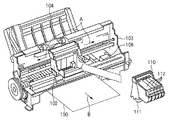
図1は、インクジェット記録装置の構成の概要を示す外観斜視図である。
<< Base Technology >>
<Description of inkjet recording apparatus>
Apparatus Configuration FIG. 1 is an external perspective view showing an outline of the configuration of an inkjet recording apparatus.
図1に示すように、インクジェット記録装置(以下、記録装置あるいはプリンタという)は、キャリッジ102を矢印A方向に往復移動させる。これは、インクジェット方式に従ってインクを吐出して記録を行なう記録ヘッド111を搭載したインクカートリッジ110をキャリッジモータM1によって発生する駆動力を伝達機構より伝えることによりなされる。それとともに、例えば、記録紙などの記録媒体150を給紙機構104を介して給紙し、記録位置まで搬送し、その記録位置において記録ヘッド111から記録媒体にインクを吐出することで記録を行なう。
As shown in FIG. 1, an ink jet recording apparatus (hereinafter referred to as a recording apparatus or a printer) reciprocates a
また、記録ヘッド111の状態を良好に維持するためにキャリッジ102を回復装置106の位置まで移動させ、間欠的に記録ヘッド111の吐出回復処理を行う。
Further, in order to maintain the state of the
記録装置100のインクカートリッジ110には、記録ヘッド111に供給するインクを貯留するインクタンク112を装着する。インクタンク112はインクカートリッジ110に対して着脱自在になっている。
An
図1に示した記録装置100はカラー記録が可能であり、そのためにインクカートリッジ112にはマゼンタ(M)、シアン(C)、イエロ(Y)、ブラック(K)のインクを夫々、収容した4つのインクタンクを搭載している。これら4つのインクタンクは夫々独立に着脱可能である。
The
さて、キャリッジ102とインクカートリッジ110とは、両部材の接合面が適正に接触されて所要の電気的接続を達成維持できるようになっている。記録ヘッド111は、記録信号に応じてエネルギーを印加することにより、複数の吐出口からインクを選択的に吐出して記録する。特に、この実施例の記録ヘッド111は、熱エネルギーを利用してインクを吐出するインクジェット方式を採用し、熱エネルギーを発生するために電気熱変換体を備える。その電気熱変換体に印加される電気エネルギーが熱エネルギーへと変換され、その熱エネルギーをインクに与えることにより生じる膜沸騰による気泡の成長、収縮によって圧力変化を生じる。この圧力変化を利用して、吐出口よりインクを吐出させる。この電気熱変換体は各吐出口のそれぞれに対応して設けられ、記録信号に応じて対応する電気熱変換体にパルス電圧を印加することによって対応する吐出口からインクを吐出する。
The
図1に示されているように、キャリッジ102はキャリッジモータM1の駆動力を伝達する伝達機構の駆動ベルトの一部に連結されており、ガイドシャフトに沿って矢印A方向に摺動自在に案内支持されるようになっている。従って、キャリッジ102は、キャリッジモータM1の正転及び逆転によってガイドシャフトに沿って往復移動する。また、キャリッジ102の移動方向(矢印A方向)に沿ってキャリッジ102の絶対位置を示すためのスケールが備えられている。この実施例では、スケールは透明なPETフィルムに必要なピッチで黒色のバーを印刷したものを用いており、その一方はシャーシ103に固着され、他方は板バネ(不図示)で支持されている。
As shown in FIG. 1, the
また、記録装置100には、記録ヘッド111の吐出口(不図示)が形成された吐出口面に対向してプラテン(不図示)が設けられている。キャリッジモータM1の駆動力によって記録ヘッド111を搭載したインクカートリッジ110が往復移動される。同時に、記録ヘッド111に記録信号を与えてインクを吐出することによって、プラテン上に搬送された記録媒体150の全幅にわたって記録が行われる。
Further, the
さらに、図1において、記録媒体150を搬送するために搬送モータM2によって駆動される搬送ローラが図示される。バネ(不図示)により記録媒体150を搬送ローラに当接するピンチローラ、ピンチローラを回転自在に支持するピンチローラホルダ、搬送ローラの一端に固着された搬送ローラギアが図示される。そして、搬送ローラギアに中間ギア(不図示)を介して伝達された搬送モータM2の回転により、搬送ローラが駆動される。
Further, in FIG. 1, a conveyance roller driven by a conveyance motor M <b> 2 for conveying the
またさらに、記録ヘッド111によって画像が形成された記録媒体150を記録装置外ヘ排出するための排出ローラがあり、搬送モータM2の回転が伝達されることで駆動されるようになっている。なお、排出ローラは記録媒体150をバネ(不図示)により圧接する拍車ローラ(不図示)により当接する。また、拍車ローラを回転自在に支持する拍車ホルダがある。
Furthermore, there is a discharge roller for discharging the
またさらに、記録装置100には、図1に示されているように、回復装置106が配設されている。これは、記録ヘッド111を搭載するインクカートリッジ110の記録動作のための往復運動の範囲外(記録領域外)の所望位置(例えば、ホームポジションに対応する位置)に設けられ、記録ヘッド111の吐出不良を回復する。
Further, the
回復装置106は、記録ヘッド111の吐出口面をキャッピングするキャッピング機構と記録ヘッド111の吐出口面をクリーニングするワイピング機構を備えている。キャッピング機構による吐出口面のキャッピングに連動して回復装置内の吸引手段(吸引ポンプ等)により吐出口からインクを強制的に排出させる。それによって、記録ヘッド111のインク流路内の粘度の増したインクや気泡等を除去するなどの吐出回復処理を行う。
The
また、非記録動作時等には、記録ヘッド111の吐出口面をキャッピング機構によるキャッピングすることによって、記録ヘッド111を保護するとともにインクの蒸発や乾燥を防止することができる。一方、ワイピング機構はキャッピング機構の近傍に配され、記録ヘッド111の吐出口面に付着したインク液滴を拭き取るようになっている。
Further, when the
これらキャッピング機構及びワイピング機構により、記録ヘッド111のインク吐出状態を正常に保つことが可能となっている。
By these capping mechanism and wiping mechanism, the ink discharge state of the
・インクジェット記録装置の制御
図2は、図1に示した記録装置の制御構成を示すブロック図である。
Control of Inkjet Printing Apparatus FIG. 2 is a block diagram showing a control configuration of the printing apparatus shown in FIG.
図2に示すように、コントローラ600は、MPU601、後述する制御シーケンスに対応したプログラム、所要のテーブル、その他の固定データを格納したROM602を備える。また、キャリッジモータM1の制御、搬送モータM2の制御、及び、記録ヘッド3の制御のための制御信号を生成する特殊用途集積回路(ASIC)603を備える。そして、画像データの展開領域やプログラム実行のための作業用領域等を設けたRAM604、MPU601、ASIC603、RAM604を相互に接続してデータの授受を行うシステムバス605を備える。さらに、以下に説明するセンサ群からのアナログ信号を入力してA/D変換し、デジタル信号をMPU601に供給するA/D変換器606などで構成される。
As shown in FIG. 2, the
また、図2において、610は画像データの供給源となるコンピュータ(或いは、画像読取り用のリーダやデジタルカメラなど)でありホスト装置と総称される。ホスト装置610と記録装置1との間ではインタフェース(I/F)611を介して画像データ、コマンド、ステータス信号等を送受信する。
In FIG. 2,
さらに、620はスイッチ群であり、電源スイッチ621、プリント開始を指令するためのプリントスイッチ622を備える。また、記録ヘッド3のインク吐出性能を良好な状態に維持するための処理(回復処理)の起動を指示するための回復スイッチ623など、操作者による指令入力を受けるためのスイッチから構成される。630はホームポジションhを検出するためのフォトカプラなどの位置センサ631、環境温度を検出するために記録装置の適宜の箇所に設けられた温度センサ632等から構成される装置状態を検出するためのセンサ群である。
さらに、640はキャリッジ2を矢印A方向に往復走査させるためのキャリッジモータM1を駆動させるキャリッジモータドライバ、642は記録媒体Pを搬送するための搬送モータM2を駆動させる搬送モータドライバである。
Further, 640 is a carriage motor driver that drives a carriage motor M1 for reciprocating scanning of the
ASIC603は、記録ヘッド3による記録走査の際に、RAM602の記憶領域に直接アクセスしながら記録ヘッドに対して記録素子(吐出ヒータ)の駆動データ(DATA)を転送する。
The
なお、図2に示す構成は、インクカートリッジ6と記録ヘッド3とが分離可能な構成であるが、これらが一体的に形成されて交換可能なヘッドカートリッジを構成しても良い
<画像データの印刷処理>
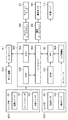
図3は、図1の記録装置により画像データを印刷する際のデータ処理を示すブロック図である。
The configuration shown in FIG. 2 is a configuration in which the ink cartridge 6 and the
FIG. 3 is a block diagram showing data processing when image data is printed by the recording apparatus of FIG.
ホスト装置は例えばPCにより構成され、オペレーティングシステムで動作するプログラムとしてはアプリケーションおよびプリンタドライバがある。 The host device is configured by a PC, for example, and there are an application and a printer driver as programs operating on the operating system.
アプリケーションJ0001はプリンタで印刷する画像データを生成する処理を実行する。この画像データもしくはその編集等がなされる前のデータは種々の媒体を介してPCに取り込むことができる。ホスト装置は、先ずデジタルカメラで撮像した例えばJPEG形式の画像データをCFカードによって取り込むことができる。また、スキャナで読み取った例えばTIFF形式の画像データやCD−ROMに格納される画像データをも取り込むことができる。さらには、インターネットを介して画像データを取り込むことができる。これらの取り込まれた画像データは、PCのモニタに表示されてアプリケーションJ0001を介した編集、加工等がなされ、例えばsRGB規格のカラー画像データが作成される。そして、ユーザからの印刷指示に基づいてこのカラー画像データがプリンタドライバにRGB(各色8bit)のデータ形式で渡される。 The application J0001 executes processing for generating image data to be printed by the printer. This image data or data before editing or the like can be taken into a PC via various media. First, the host device can capture, for example, JPEG format image data captured by a digital camera using a CF card. Also, for example, TIFF format image data read by a scanner or image data stored in a CD-ROM can be captured. Furthermore, image data can be captured via the Internet. These captured image data are displayed on the monitor of the PC and edited, processed, etc. via the application J0001, and for example, color image data of the sRGB standard is created. Then, based on the print instruction from the user, the color image data is transferred to the printer driver in the RGB (8 bits for each color) data format.
プリンタドライバは、カラーマッチング処理J0002、色分解処理J0003、γ補正J0004、ハーフトーニングJ0005、および印刷データ作成J0006の各処理機能を有している。 The printer driver has processing functions of color matching processing J0002, color separation processing J0003, γ correction J0004, halftoning J0005, and print data creation J0006.
カラーマッチング処理J0002は色域(Gamut)のマッピングを行う。例えば、sRGB規格の画像データによって再現される色域を、本プリントシステムのプリンタによって再現される色域内に写像する3次元LUTおよび補間演算を用いてデータの変換を行う。つまり、入力されたRGB(各色8ビット)の画像データをプリンタの色域内のRGB(各色8bit)の画像データに変換する。 The color matching process J0002 performs color gamut mapping. For example, data conversion is performed using a three-dimensional LUT and an interpolation operation for mapping a color gamut reproduced by image data of the sRGB standard into a color gamut reproduced by a printer of the present printing system. That is, the input RGB (8 bits for each color) image data is converted into RGB (8 bits for each color) image data in the printer color gamut.
色分解処理J0003は、上記色域への変換(マッピング)がなされたRGBの画像データに基づき、このデータが表す色を再現するインクの組み合わせに対応した色分解データを生成する。つまり、ここではCMYKの各成分により表現されるデータを生成する。この処理はカラーマッチング処理と同様3次元LUTに補間演算を併用して行う。出力は例えば各色8ビットであり、C、M、Y、Kの色材量に対応した値である。 The color separation process J0003 generates color separation data corresponding to a combination of inks that reproduce colors represented by this data, based on the RGB image data that has been converted (mapped) into the color gamut. That is, here, data represented by each component of CMYK is generated. This process is performed by using a three-dimensional LUT together with an interpolation operation as in the color matching process. The output is, for example, 8 bits for each color, and is a value corresponding to the color material amounts of C, M, Y, and K.
γ補正J0004は、色分解処理J0003によって求められた色分解データの各色のデータごとに階調値変換を行う。具体的には、プリンタの各色インクの階調特性に応じた1次元LUTを用いることにより、上記色分解データがプリンタの階調特性に線形的に対応づけられるような変換を行う。ハーフトーニングJ0005は、8ビットの色分解データC、M、Y、Kそれぞれについて4ビットのデータに変換する量子化を行う。本実施形態では、誤差拡散法を用いて各色の8ビットデータを4ビットデータに変換する。 The γ correction J0004 performs gradation value conversion for each color data of the color separation data obtained by the color separation processing J0003. Specifically, by using a one-dimensional LUT corresponding to the gradation characteristics of each color ink of the printer, conversion is performed so that the color separation data is linearly associated with the gradation characteristics of the printer. Halftoning J0005 performs quantization that converts 8-bit color separation data C, M, Y, and K into 4-bit data. In the present embodiment, 8-bit data of each color is converted into 4-bit data using an error diffusion method.
この4ビットのデータは、後述する記録装置におけるドット配置のパターン化処理における配置パターンを示すためのインデックスとなるデータである。最後に、印刷データ作成処理J0006によって、上記4ビットのインデックスデータを内容とする印刷イメージデータに印刷制御情報を加えた印刷データを作成する。 The 4-bit data is data serving as an index for indicating an arrangement pattern in a dot arrangement patterning process in a printing apparatus described later. Finally, print data is created by adding print control information to the print image data containing the 4-bit index data by print data creation processing J0006.
なお、上述したアプリケーションおよびプリンタドライバの処理は、CPUがプログラムを実行することにより実現される。その際、プログラムはROMもしくはハードディスクから読み出されて用いられ、また、その処理実行に際してRAMがワークエリアとして用いられる。 Note that the processing of the application and printer driver described above is realized by the CPU executing a program. At this time, the program is read from the ROM or hard disk and used, and the RAM is used as a work area when executing the processing.
記録装置は、印刷する画像データ処理に関して、ドット配置パターン化処理J0007およびマスクデータ変換処理J0008を実行する。 The recording apparatus executes a dot arrangement patterning process J0007 and a mask data conversion process J0008 regarding the image data processing to be printed.
ドット配置パターン化処理J0007は、入力された画像データについて、画素ごとに、4ビットのインデックスデータ(階調値情報)に対応したドット配置パターンに従ってドット配置を行う。4ビットデータで表現される各画素に対し、その画素の階調値に対応したドット配置パターンを割当てることで、画素内の複数のエリア各々にドットのオン・オフが定義され、そして1画素内の各エリアごとに「1」または「0」の吐出データが配置される。このようにして得られる1ビットの吐出データは、パスマスク選択用の1ビットを用いて、2種類あるマスクパターンのどちらかが選択され、選択されたマスクパターンに基づきマスクデータ変換処理J0008によってマスク処理がなされる。すなわち、記録ヘッドによる所定幅の走査領域の記録を複数回の走査で完成するための各走査の吐出データを、それぞれの走査に対応したマスクを用いた処理によって生成する。 The dot arrangement patterning process J0007 performs dot arrangement for the input image data in accordance with a dot arrangement pattern corresponding to 4-bit index data (tone value information) for each pixel. By assigning a dot arrangement pattern corresponding to the gradation value of each pixel to each pixel expressed by 4-bit data, dot on / off is defined in each of a plurality of areas in the pixel, and within one pixel Discharge data “1” or “0” is arranged for each area. The 1-bit ejection data obtained in this way uses one bit for selecting a pass mask, and one of two types of mask patterns is selected. Based on the selected mask pattern, mask processing is performed by mask data conversion processing J0008. Is made. That is, the ejection data for each scan for completing the recording of the scanning region of the predetermined width by the recording head by a plurality of scans is generated by a process using a mask corresponding to each scan.
走査ごとの吐出データC、M、Y、Kは、適切なタイミングでヘッド駆動回路J0009に送られ、これにより、記録へッドJ0010が駆動されて吐出データに従ってそれぞれのインクが吐出される。 The ejection data C, M, Y, and K for each scan are sent to the head drive circuit J0009 at an appropriate timing, whereby the recording head J0010 is driven and each ink is ejected according to the ejection data.
上述のドット配置パターン化処理やマスクデータ変換処理は、一般的には専用のハードウエア回路を用い記録装置の制御部を構成するCPUの制御の下に実行される。ただし、これらの処理は記録装置のCPUが制御ソフトウェアを実行することによって行われてもよい。さらに、これらの処理の全部または一部を、ホストコンピュータ(PC)の例えばプリンタドライバによって実現するよう構成しても良い。 The above-described dot arrangement patterning process and mask data conversion process are generally executed under the control of a CPU that constitutes the control unit of the printing apparatus using a dedicated hardware circuit. However, these processes may be performed by the CPU of the recording apparatus executing control software. Further, all or part of these processes may be realized by, for example, a printer driver of a host computer (PC).
以下、上述の各処理について、さらに詳細に説明する。 Hereinafter, each process described above will be described in more detail.
・カラーマッチング処理(J0002)
カラーマッチング処理とは、モニタで表現された色をプリンタで再現した場合に色みの一致をするための処理である。CIE−L*a*b*等の色空間において定義されたモニタのGamutからプリンタのGamutへの色空間圧縮を行う。色空間圧縮の手法としては、Perceptualと呼ばれる知覚的な一致を優先したカラーマッチングがある。また、Colorimetricと呼ばれる色測的な一致を優先したカラーマッチングや、Saturationと呼ばれる鮮やかさを優先したカラーマッチング等の手法がある。
・ Color matching processing (J0002)
The color matching process is a process for matching colors when a color expressed on a monitor is reproduced on a printer. Color space compression is performed from the monitor Gamut defined in the color space such as CIE-L * a * b * to the printer Gamut. As a color space compression method, there is color matching that gives priority to perceptual matching called Perceptual. Further, there are methods such as color matching called colorimetric giving priority to colorimetric matching, and color matching giving priority to vividness called saturation.
・色分解処理(J0003)
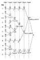
色分解処理とは、上述の通り、入力されてくるRGBデータをプリンタの記録剤であるCMYKインク色に対応する色材量に変換するための処理である。実際の処理では、図4に示されているような3次元格子状LUTに入力RGBの値に対応したCMYKの値が格納されており、格子間のデータが入力されてきた場合は、四面体補間処理や立方体補間処理等の3次元の補間演算処理により計算される。例えば、Y〜Mの色相は、YインクとMインクにて混色され、M〜C色相はMインクとCインクにて混色され、そして、C〜Y色相はCインクとYインクにより混色される。
・ Color separation (J0003)
As described above, the color separation process is a process for converting the input RGB data into a color material amount corresponding to the CMYK ink color that is the recording agent of the printer. In actual processing, CMYK values corresponding to the input RGB values are stored in a three-dimensional grid LUT as shown in FIG. 4, and when data between grids is input, a tetrahedron is obtained. It is calculated by a three-dimensional interpolation calculation process such as an interpolation process or a cube interpolation process. For example, Y to M hues are mixed with Y ink and M ink, M to C hues are mixed with M ink and C ink, and C to Y hues are mixed with C ink and Y ink. .
図5は、無彩色であるグレイラインのハイライトからシャドーにおけるインク構成を示した図である。中間明度よりハイライトよりの部分では、Cインク、Mインク、そして、Yインクの3色が混色される。一方、中間明度からシャドーよりの部分にかけては、Cインク、Mインク、Yインク、そして、Kインク4色で混色されている。 FIG. 5 is a diagram illustrating an ink configuration in shadows from gray line highlights which are achromatic colors. In the area from the intermediate brightness to the highlight, the three colors of C ink, M ink, and Y ink are mixed. On the other hand, from the intermediate lightness to the shadow area, C ink, M ink, Y ink, and K ink are mixed in four colors.
・ハーフトーニング(J0005)
ハーフトーニングは画像走査部とハーフトーン処理部とから構成される。
・ Half Toning (J0005)
Halftoning includes an image scanning unit and a halftone processing unit.
図6は、画像走査部が行う、画像データの走査処理を説明する図である。画像走査部は、複数の画素が配列して構成される画像データから、処理を行うべき画素を1画素ずつ選択し、ハーフトーン処理部の入力端子B0001に画素データを入力する。図において、各マス目は個々の画素を示し、B0015は画像の左上端に位置する画素、B0016は画像の右下端に位置する画素をそれぞれ示している。 FIG. 6 is a diagram for explaining image data scanning processing performed by the image scanning unit. The image scanning unit selects pixels to be processed one by one from image data configured by arranging a plurality of pixels, and inputs the pixel data to the input terminal B0001 of the halftone processing unit. In the figure, each square represents an individual pixel, B0015 represents a pixel located at the upper left end of the image, and B0016 represents a pixel located at the lower right end of the image.
走査処理は、まず、画像領域の左上端の画素B0015を選択する画素(以下着目画素とも言う)とすることで開始される。続いて、図の矢印の方向に右方向に1画素ずつ着目画素を切り替えながら処理を進めていく。最上端列の右端まで処理が終了すると、次に1段下の画素列の左端画素に着目画素を移す。このような順番で、図の矢印に沿って処理走査を進めて行き、最終画素となる右下端の画素B0016まで処理が到達すると、本画像の処理走査は完了する。 The scanning process is started by first selecting the pixel B0015 at the upper left corner of the image area as a pixel to be selected (hereinafter also referred to as a target pixel). Subsequently, the processing proceeds while switching the pixel of interest one pixel at a time in the direction of the arrow in the figure. When the processing is completed up to the right end of the uppermost row, the target pixel is moved to the left end pixel of the pixel row one stage below. In this order, the process scan proceeds along the arrows in the figure, and when the process reaches the lower right pixel B0016 as the final pixel, the process scan of the main image is completed.
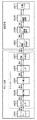
図7は、ハーフトーン処理部の構成を説明するためのブロック図である。B0001は画素データの入力端子、B0002は累積誤差加算部、B0003は入力画素データを2つ以上の階調数に変換する際の量子化閾値を設定する端子である。また、B0004は量子化部、B0005は量子化誤差を演算する誤差演算部、B0006は量子化誤差を拡散する誤差拡散部、B0007は累積誤差を格納する累積誤差メモリ、およびB0008は一連の処理後に形成された画素データの出力端子である。 FIG. 7 is a block diagram for explaining the configuration of the halftone processing unit. B0001 is an input terminal for pixel data, B0002 is a cumulative error adding unit, and B0003 is a terminal for setting a quantization threshold for converting the input pixel data into two or more gradation numbers. B0004 is a quantization unit, B0005 is an error calculation unit that calculates a quantization error, B0006 is an error diffusion unit that diffuses a quantization error, B0007 is a cumulative error memory that stores a cumulative error, and B0008 is after a series of processing. It is an output terminal for the formed pixel data.
入力端子B0001には、前述した画像走査部が全画像より選択した画素の、画素データが順次入力される。ハーフトーン処理部は、入力された個々の画素データに対し順番に処理を施し、出力端子B0008より1画素分ずつ出力していく構成となっている。 Pixel data of pixels selected from all images by the image scanning unit described above is sequentially input to the input terminal B0001. The halftone processing unit is configured to sequentially process the input individual pixel data and output one pixel at a time from the output terminal B0008.
図8は、ハーフトーン処理部の動作フローチャートである。なお、以下の処理はインクの色ごとに実行されるが、以下では1つの色に着目して説明する。 FIG. 8 is an operation flowchart of the halftone processing unit. Note that the following processing is executed for each ink color, but the following description will be focused on one color.
ステップSB0009では、画像走査部により、処理すべき画像データが入力される。 In step SB0009, image data to be processed is input by the image scanning unit.
ステップSB0010では、累積誤差加算部B0002において、入力された画素データに対し、累積誤差メモリB0007に格納された、画素位置に対応する累積誤差値が加算される。 In step SB0010, the accumulated error adding unit B0002 adds the accumulated error value corresponding to the pixel position stored in the accumulated error memory B0007 to the input pixel data.
図9は、累積誤差メモリB0007に格納される、データおよびデータの格納形態を説明するための図である。累積誤差メモリB0007には、1つの記憶領域E0とW個の記憶領域E(x)(x=1〜Wの整数)が配置される。ここで、Wは処理対象となっている画像データの横方向の画素数を表している。また、それぞれの領域には、注目画素に適用される量子化誤差E(x)が格納されている。なお、量子化誤差の値は、後述する方法によって得られるものであるが、処理開始当初は全ての領域において、初期値0にて初期化されるものとする。 FIG. 9 is a diagram for explaining data and a data storage form stored in the cumulative error memory B0007. In the cumulative error memory B0007, one storage area E0 and W storage areas E (x) (x is an integer from 1 to W) are arranged. Here, W represents the number of pixels in the horizontal direction of the image data to be processed. Each region stores a quantization error E (x) applied to the pixel of interest. Note that the quantization error value is obtained by a method described later, but is initially initialized with an initial value of 0 in all regions.
そして、本ステップにおいて、累積誤差加算部B0002では、入力された画素データに対し、当該画素の横方向の位置x(0<x≦W)に対応した誤差メモリE(x)の値が加算される。すなわち、入力端子B0001に入力された画素データをI、ステップB0010による累積誤差加算後の画素データをI’とすると、
I’=I+E(x)
となる。
In this step, the accumulated error adding unit B0002 adds the value of the error memory E (x) corresponding to the horizontal position x (0 <x ≦ W) of the pixel to the input pixel data. The That is, assuming that the pixel data input to the input terminal B0001 is I and the pixel data after adding the accumulated error in step B0010 is I ′,
I ′ = I + E (x)
It becomes.
ステップSB0011では、累積誤差加算後の画素データI’と閾値設定端子B0003により入力された閾値とを比較し、量子化処理を行う。ここでは、8つの閾値と累積誤差加算後の画素データI’とを比較することにより、量子化後の画像データを9段階に振り分けて、出力端子B0008に送る出力画素データの値を決定するものとする。すなわち、累積誤差加算部B0002から入力された画素データの値が0から255の範囲の整数値とすれば、出力階調値Oは次式により決定される。 In step SB0011, the pixel data I ′ after the cumulative error addition is compared with the threshold value input through the threshold setting terminal B0003, and the quantization process is performed. Here, by comparing the eight threshold values and the pixel data I ′ after adding the accumulated error, the quantized image data is divided into nine stages and the value of the output pixel data sent to the output terminal B0008 is determined. And That is, if the pixel data value input from the cumulative error addition unit B0002 is an integer value in the range of 0 to 255, the output gradation value O is determined by the following equation.
O=0 (I’<16) ・・・(式1)
O=32 (16≦I’<48) ・・・(式2)
O=64 (48≦I’<80) ・・・(式3)
O=96 (80≦I’<112) ・・・(式4)
O=128 (112≦I’<144) ・・・(式5)
O=160 (144≦I’<176) ・・・(式6)
O=192 (176≦I’<208) ・・・(式7)
O=224 (208≦I’<240) ・・・(式8)
O=255 (I’≧240) ・・・(式9)
ここで、説明の都合上、各出力階調値Oに対し以下のような名称を与える。すなわち、O=0をレベル0、O=32をレベル1、O=64をレベル2、O=96をレベル3、O=128をレベル4、O=160をレベル5、O=192をレベル6、O=224をレベル7、そしてO=225をレベル8とそれぞれ称することにする。
O = 0 (I ′ <16) (Formula 1)
O = 32 (16 ≦ I ′ <48) (Formula 2)
O = 64 (48 ≦ I ′ <80) (Formula 3)
O = 96 (80 ≦ I ′ <112) (Formula 4)
O = 128 (112 ≦ I ′ <144) (Formula 5)
O = 160 (144 ≦ I ′ <176) (Expression 6)
O = 192 (176 ≦ I ′ <208) (Expression 7)
O = 224 (208 ≦ I ′ <240) (Equation 8)
O = 255 (I ′ ≧ 240) (Equation 9)
Here, for convenience of explanation, the following names are given to the output gradation values O. That is, O = 0 is
ステップSB0012では、誤差演算部B0005において、累積誤差加算後の画素データI’と出力画素値Oとの差分、すなわち量子化誤差Eを算出する。 In step SB0012, the error calculation unit B0005 calculates a difference between the pixel data I ′ after the accumulated error addition and the output pixel value O, that is, a quantization error E.
E=I’−O ・・・(式10)
ステップSB0013では、誤差拡散部B0006において、着目している画素の横方向位置xに応じて、誤差の拡散処理を行う。具体的には、記憶領域E0およびE(x)に格納すべき量子化誤差を、以下の処理に従って算出し、累積誤差メモリに格納する。
E = I′−O (Formula 10)
In step SB0013, the error diffusion unit B0006 performs error diffusion processing according to the horizontal position x of the pixel of interest. Specifically, the quantization error to be stored in the storage areas E0 and E (x) is calculated according to the following process and stored in the accumulated error memory.
E(x+1)←E(x+1)+E×7/16 (x<W)・・・(式11)
E(x−1)←E(x−1)+E×3/16 (x>1)・・・(式12)
E(x)←E0+E×5/16 (1<x<W)・・・(式13)
E(x)←E0+E×8/16 (x=1)・・・(式14)
E(x)←E0+E×13/16 (x=W)・・・(式15)
E0←E×1/16 (x<W)・・・(式16)
E0←0 (x=W)・・・(式17)
以上で、入力端子B0001に入力された1画素分の誤差拡散処理が完了する。
E (x + 1) ← E (x + 1) + E × 7/16 (x <W) (Expression 11)
E (x−1) ← E (x−1) + E × 3/16 (x> 1) (Equation 12)
E (x) ← E0 + E × 5/16 (1 <x <W) (Equation 13)
E (x) ← E0 + E × 8/16 (x = 1) (Expression 14)
E (x) ← E0 + E × 13/16 (x = W) (Equation 15)
E0 ← E × 1/16 (x <W) (Expression 16)
E0 ← 0 (x = W) (Expression 17)
This completes the error diffusion process for one pixel input to the input terminal B0001.
ステップSB0014では、ステップSB0009〜ステップSB0013の各処理が、画像データに含まれる全画素に対して施されたか否かを判定する。すなわち、画像走査部が選択した画素が、図7のB0016まで達したか否かを判定する。B0016まで達していない場合には、矢印の方向に着目画素を1つ分進め、ステップSB0009に進む。全画素に対して処理が行われたと判定された場合、ハーフトーン処理を終了する。 In step SB0014, it is determined whether each process of step SB0009 to step SB0013 has been performed on all the pixels included in the image data. That is, it is determined whether or not the pixel selected by the image scanning unit has reached B0016 in FIG. If it has not reached B0016, the target pixel is advanced by one in the direction of the arrow, and the process proceeds to step SB0009. If it is determined that processing has been performed for all pixels, the halftone processing is terminated.
図10は、ハーフトーン処理前の画像と、ハーフトーン処理後の画像を例示的に示した図である。図において、イエロー(Y)用に作成された画像データB0017に対しハーフトーン処理を施したものをB0019に示している。また、特色インクであるレッド(R)用に作成された画像データB0018に対しハーフトーン処理を施したものをB0020、として示している。 FIG. 10 is a diagram exemplarily showing an image before halftone processing and an image after halftone processing. In the figure, B0019 shows the image data B0017 created for yellow (Y) subjected to halftone processing. Also, B0020 is obtained by performing halftone processing on the image data B0018 created for red (R) which is the special color ink.
B0017では、全画素における画素の値が10となっている。これに対しハーフトーン処理を施した後の画像B0019では、O=0(レベル0)であるB0021と、O=32(レベル1)であるB0022との、2つのレベル(濃度)の画素が、一様に分散されて存在している状態となっている。また、B0018では、全画素における画素データが100となっている。これに対しハーフトーン処理を施した後の画像B0020では、O=96(レベル4)であるB0023と、O=128(レベル5)であるB0024との、2つのレベル(濃度)の画素が、一様に分散されて存在している状態となっている。いずれも、オリジナルの画像においては、全画素で同一レベルであった画素データの値が、ハーフトーン処理後には複数のレベルの画素に分散される。ただし、画像全体で捉えた場合には入力時のデータ値が保存されている構成となっている。 In B0017, the pixel value of all the pixels is 10. On the other hand, in the image B0019 after being subjected to the halftone process, pixels of two levels (density), B0021 where O = 0 (level 0) and B0022 where O = 32 (level 1), It is in a state of being uniformly distributed. In B0018, the pixel data in all the pixels is 100. On the other hand, in the image B0020 after the halftone process is performed, pixels at two levels (density), B0023 where O = 96 (level 4) and B0024 where O = 128 (level 5), It is in a state of being uniformly distributed. In any case, in the original image, the pixel data values that are at the same level in all the pixels are distributed to a plurality of levels of pixels after the halftone process. However, when the entire image is captured, the data value at the time of input is stored.
・印刷データの生成(J0006)
上述のハーフトーン処理を施した画像データに対して、以下で説明する印刷制御情報を付加する処理を行うことにより印刷データを生成する。
・ Generation of print data (J0006)
Print data is generated by performing processing for adding print control information described below to the image data subjected to the above-described halftone processing.
図11は、印刷データの内部構成を示した図である。印刷データは、大まかに、印刷の制御を司る印刷制御情報、および、印刷イメージ情報(印刷イメージデータともいう)から構成されている。更に印刷制御情報は、その画像を記録する「メディア情報」、印刷の「品位情報」、および給紙方法等のような「その他制御情報」とから構成されている。 FIG. 11 is a diagram showing an internal configuration of print data. The print data is roughly composed of print control information for controlling printing and print image information (also referred to as print image data). Further, the print control information includes “media information” for recording the image, “quality information” for printing, and “other control information” such as a paper feed method.
ここで、メディア情報には、記録の対象となる用紙の種類が記述されており、普通紙、光沢紙、コート紙などのうち、いずれか1種類の用紙が規定されている。品位情報には印刷の品位が記述されており、高速印刷、高品位印刷のいずれかの品位が規定されている。なお、これらの印刷制御情報はホストPCにてユーザが指定した内容に基づいて形成されるものである。更に、印刷イメージ情報(印刷イメージデータ)では前述のハーフトーン処理によって生成された画像データが記述さている。 Here, in the media information, the type of paper to be recorded is described, and any one of plain paper, glossy paper, coated paper, etc. is defined. The quality information describes the quality of printing and defines either high speed printing or high quality printing. The print control information is formed based on the contents designated by the user on the host PC. Further, the print image information (print image data) describes the image data generated by the above-described halftone process.
なお、上述した処理(J0001〜J0006)は、ホスト装置にインストールされたプリンタドライバによって処理されるよう説明した。しかし、これらの処理の全部または一部を記録装置で行うよう構成しても良い。 The above-described processing (J0001 to J0006) has been described as being processed by the printer driver installed in the host device. However, all or part of these processes may be performed by the recording apparatus.
・ドット配置パターン化処理
上述したハーフトーン処理において、256値の多値濃度情報(8ビットデータ)を9値の階調値情報(4ビットデータ)までにレベル数を下げている。しかし、実際にインクジェット記録装置が記録媒体上に記録できるのは、インクを記録するか否かの2値である。そこで、ドット配置パターン化処理では、0〜8の多値レベルをドットの有無を決定する2値レベルまで低減する役割を果たす。具体的には、このドット配置パターン化処理J0007では、ハーフトーン処理部からの出力値であるレベル0〜8の4ビットデータで表現される各画素に、その画素の階調値(レベル0〜8)に対応したドット配置パターンを割当てる。これにより1画素内の複数のエリア各々にドットのオン・オフを定義し、1画素内の各エリアに「1」または「0」の1ビットの吐出データを配置する。
In the halftone process described above, the number of levels is reduced from 256-level multi-value density information (8-bit data) to 9-level tone value information (4-bit data). However, what the inkjet recording apparatus can actually record on the recording medium is a binary value indicating whether or not to record ink. Thus, the dot arrangement patterning process plays a role of reducing the multi-value level of 0 to 8 to the binary level that determines the presence or absence of dots. Specifically, in this dot arrangement patterning process J0007, the gradation value (
図12は、画素の各階調に対応するドット配置パターンの例を示す図である。図の左に示した各レベル値は、ハーフトーン処理部からの出力値であるレベル0〜レベル8に相当している。右側に配列した縦2エリア×横4エリアで構成される各マトリクスの領域は、ハーフトーン処理で出力された1画素の領域に対応するものである。また、1画素内の各エリアは、インクのドットのオン・オフが定義される最小単位に相当するものである。丸印を記入したエリアがドットの記録を行うエリアを示しており、レベル数が上がるに従って、記録するドット数も1つずつ増加している。
FIG. 12 is a diagram illustrating an example of a dot arrangement pattern corresponding to each gradation of a pixel. Each level value shown on the left of the figure corresponds to
図の横軸に対応する(4n)〜(4n+3)は、nに1以上の整数を代入することにより、入力画像の左端からの横方向の画素位置を示している。その下に示される各パターンは、同一の入力レベルにおいても画素位置に応じて互いに異なる複数のパターンが用意されていることを示している。すなわち、同一のレベルが入力された場合にも、記録媒体上では(4n)〜(4n+3)に示した4種類のドット配置パターンが巡回して割当てられる構成となっているのである。 (4n) to (4n + 3) corresponding to the horizontal axis in the figure indicate pixel positions in the horizontal direction from the left end of the input image by substituting an integer of 1 or more for n. Each pattern shown below indicates that a plurality of different patterns are prepared according to pixel positions even at the same input level. That is, even when the same level is input, four types of dot arrangement patterns shown in (4n) to (4n + 3) are cyclically assigned on the recording medium.
図12の各ドット配置パターンにおいては、縦方向を記録ヘッドの吐出口が配列する方向、横方向を記録ヘッドの走査方向としている。よって、上述のように同一レベルに対しても様々なドット配列で記録できる構成にしておくことは、ドット配置パターンの上段に位置するノズルと下段に位置するノズルとで吐出回数を分散させたり、記録装置特有の様々なノイズを分散させるという効果が得られる。 In each dot arrangement pattern of FIG. 12, the vertical direction is the direction in which the ejection ports of the recording head are arranged, and the horizontal direction is the scanning direction of the recording head. Therefore, as described above, it is possible to record with various dot arrangements even for the same level, such that the number of ejections is distributed between the nozzles located in the upper stage and the nozzles located in the lower stage of the dot arrangement pattern, The effect of dispersing various noises peculiar to the recording apparatus can be obtained.
・マスクデータ変換処理
上述したドット配置パターン化処理により、記録媒体上の各エリアに対するドットの有無は決定されている。そのため、この情報をそのまま記録ヘッドの駆動回路に入力すれば、所望の画像を記録することは可能である。しかし、インクジェット記録装置においては、主に高画質化のためマルチパス記録という記録方法が採用されている。以下にマルチパス記録方法について簡単に説明する。
Mask data conversion process With the dot arrangement patterning process described above, the presence or absence of dots for each area on the recording medium is determined. Therefore, if this information is directly input to the drive circuit of the recording head, a desired image can be recorded. However, in the ink jet recording apparatus, a recording method called multi-pass recording is mainly employed for improving image quality. The multipass recording method will be briefly described below.
図13は、マルチパス記録を説明するための図である。なお、以下の処理はインクの色ごとに実行されるが、以下では1つの色に着目して説明する。 FIG. 13 is a diagram for explaining multi-pass printing. Note that the following processing is executed for each ink color, but the following description will be focused on one color.
P0001は記録ヘッドを示し、ここでは簡単のため16個のノズルを有するものとする。ノズル列は、図のように第1〜第4の4つのノズル群に論理的に分割され、各ノズル群には4つずつのノズルが含まれている。P0002はマスクパターンを示し、各ノズルにより記録可能なエリアを黒塗りで示している。各ノズル群に対応するマスクパターンは互いに補完の関係にあり、これらを重ね合わせると4×4のエリアに対応した領域の記録が完成される構成となっている。 P0001 indicates a recording head. Here, for simplicity, it is assumed that it has 16 nozzles. The nozzle row is logically divided into first to fourth four nozzle groups as shown in the figure, and each nozzle group includes four nozzles. P0002 indicates a mask pattern, and an area that can be recorded by each nozzle is indicated by black. The mask patterns corresponding to each nozzle group are complementary to each other. When these are overlapped, recording of a region corresponding to a 4 × 4 area is completed.
P0003〜P0006で示した各パターンは、記録走査を重ねていくことによって画像が完成されていく様子を例示的に示したものである。各記録走査が終了するたびに、記録媒体は搬送ローラにより図の矢印の方向にノズル群の幅分(つまりノズル4個分)搬送される。よって、記録媒体上の領域の画像は4回の記録走査が完了後、画像形成が完了する構成となっている。このように、記録媒体の領域に対して複数回の走査で複数のノズル群によって画像を形成することにより、ノズル特有のばらつきや記録媒体の搬送精度のばらつき等を低減させる効果がある。 Each pattern indicated by P0003 to P0006 exemplifies a state in which an image is completed by overlapping recording scans. When each recording scan is completed, the recording medium is conveyed by the width of the nozzle group (that is, four nozzles) in the direction of the arrow in the drawing by the conveying roller. Therefore, the image of the area on the recording medium is configured to complete image formation after four recording scans are completed. In this way, by forming an image with a plurality of nozzle groups in a plurality of scans with respect to the area of the recording medium, there is an effect of reducing variations peculiar to nozzles, variations in conveyance accuracy of the recording medium, and the like.
図14は、記録ヘッドの構成を示す図である。また、図15は、図14の記録ヘッドにより実際に適用されるマスクパターンの例を示した図である。 FIG. 14 is a diagram illustrating the configuration of the recording head. FIG. 15 is a diagram showing an example of a mask pattern actually applied by the recording head of FIG.
記録ヘッドはYMCKの各色について768個のノズルを有している。H2000〜H2300は、それぞれ異なるインク色に対応する記録素子の列(以下ノズル列ともいう)である。記録素子基板H1100には、シアンインクの供給されるノズル列H2000、マゼンタインクの供給されるノズル列H2100、イエローインクの供給されるノズル列H2200、そして、ブラックインクの供給されるノズル列H2300の4色分のノズル列が構成されている。ここでは、各ノズル列は、記録媒体の搬送方向(副走査方向)に1200dpi(dot/inch)の間隔で並ぶ768個のノズルによって構成されているものとして説明する。 The recording head has 768 nozzles for each color of YMCK. H2000 to H2300 are printing element rows (hereinafter also referred to as nozzle rows) corresponding to different ink colors. The recording element substrate H1100 includes four nozzle rows H2000 to which cyan ink is supplied, nozzle row H2100 to which magenta ink is supplied, nozzle row H2200 to which yellow ink is supplied, and nozzle row H2300 to which black ink is supplied. A color nozzle row is configured. Here, each nozzle row is described as being composed of 768 nozzles arranged at an interval of 1200 dpi (dot / inch) in the recording medium conveyance direction (sub-scanning direction).
そのため、マルチパス記録のために4つに分割されたノズル群にはそれぞれ192個ずつのノズルが属している。なお、マスクパターン大きさは、縦方向がノズル数と同等の768エリア、横方向は256エリアとなっており、前述した例と同様に4つのノズル群で互いに補完の関係を保つような構成となっている。 Therefore, 192 nozzles belong to each nozzle group divided into four for multi-pass printing. Note that the mask pattern size is 768 areas in the vertical direction equal to the number of nozzles and 256 areas in the horizontal direction, and the configuration is such that the four nozzle groups maintain a complementary relationship to each other as in the above example. It has become.
ここでは、マスクパターンのデータが記録装置本体内のメモリに格納してある。また、マスクデータ変換処理においては、当該マスクパターンのデータと上述したドット配置パターン化処理の出力信号との間でAND処理をかける。このようにすることにより、各記録走査で実際に吐出させる記録画素が決定され、出力信号として記録ヘッドH1001の駆動回路に入力される。 Here, mask pattern data is stored in a memory in the recording apparatus main body. In the mask data conversion process, an AND process is performed between the mask pattern data and the output signal of the dot arrangement patterning process described above. In this way, the recording pixels that are actually ejected in each recording scan are determined and input to the drive circuit of the recording head H1001 as an output signal.
なお、多数の小液滴を高周波数で吐出するようなインクジェット記録装置の記録ヘッドにおいては、記録動作時に記録部近傍に気流が生じる。この気流が特に記録ヘッドの端部に位置するノズルの吐出方向に影響を与えることが知られている。そのため、図15に示されるように、各ノズル群また同一のノズル群の中でも、領域によって記録率(マスクパターンの開口率)の分布に偏りを持たせている。具体的には、端部のノズルの記録率を中央部の記録率に対して低減した構成となっている。このような構成とすることにより、端部のノズルが吐出したインク滴の着弾位置ずれを低減することが可能となる。 Note that in a recording head of an ink jet recording apparatus that discharges a large number of small droplets at a high frequency, an air flow is generated in the vicinity of the recording unit during a recording operation. It is known that this air flow particularly affects the ejection direction of nozzles located at the end of the recording head. For this reason, as shown in FIG. 15, the distribution of the recording rate (the aperture ratio of the mask pattern) is biased depending on the region in each nozzle group or the same nozzle group. Specifically, the recording rate of the nozzle at the end is reduced with respect to the recording rate at the center. By adopting such a configuration, it is possible to reduce the landing position deviation of the ink droplets ejected by the nozzles at the end portions.
なお、上述した処理(J0007、J0008)は、記録装置によって処理されるよう説明した。しかし、これらの処理の全部または一部をホスト装置で行うよう構成しても良い。 The above-described processing (J0007, J0008) has been described as being processed by the recording apparatus. However, all or part of these processes may be performed by the host device.
<<色の明度に基づくインク吐出順序の制御>>
以下では、第1実施形態において本発明の中心となる構成および動作について説明する。なお、装置の構成(図1、図2)については上述の前提技術と同様のため説明は省略する。
<< Control of ink ejection sequence based on color brightness >>
Below, the structure and operation | movement which become the center of this invention in 1st Embodiment are demonstrated. Note that the configuration of the apparatus (FIGS. 1 and 2) is the same as that of the above-described base technology, and thus description thereof is omitted.
<画像データの印刷処理>
図16は、第1実施形態の記録装置により画像データを印刷する際のデータ処理を示すブロック図である。前提技術(図3)との差は、色分解処理J0003において、色分解データの生成に加え、後述するJ0008にて規定されたマスクの選択に使用される1ビットデータを生成する点にある。そのため、色分解処理J0003により、画像データは各色9ビットとして出力される。そのうちの8ビットは、C、M、Y、Kの色材量に対応した値、残りの1ビットは、マスクの選択に使用される値である。そのため、マスクデータ変換処理(J0008)に該1ビットデータが使用されるまでの間(J0003〜J0008)各色の画像データは図3に比較し1ビットずつ増加している。つまり、この1ビット値を用いて、当該色のインクによる記録の順序制御を行うのである。
<Image data printing process>
FIG. 16 is a block diagram showing data processing when image data is printed by the recording apparatus of the first embodiment. The difference from the base technology (FIG. 3) is that, in the color separation process J0003, in addition to the generation of color separation data, 1-bit data used for mask selection defined in J0008 described later is generated. Therefore, the image data is output as 9 bits for each color by the color separation processing J0003. Of these, 8 bits are values corresponding to the color material amounts of C, M, Y, and K, and the remaining 1 bit is a value used for mask selection. Therefore, the image data of each color is increased by 1 bit as compared with FIG. 3 until the 1-bit data is used in the mask data conversion process (J0008) (J0003 to J0008). That is, using this 1-bit value, the order of recording with the ink of the color is controlled.
<マスク設計>
図17は、記録ヘッドのノズル列を6分割し、分離した2つのマルチパス(4パス)記録を実現するマスク設計を例示的に示す図である。ここでは2つのマルチパス記録用のマスクパターン(M1およびM2)間は2分割分の間隔を有している。そして、4色のインクの各々はM1およびM2の何れかのマスクを用いて記録される。そのため、全記録色に対しては6パスによる記録となるが、各色に対しては、マスクM1(B1〜B4)あるいはマスクM2(B3〜B6)の4パスによる記録となる。
<Mask design>
FIG. 17 is a diagram exemplarily showing a mask design that realizes two separated multi-pass (4-pass) printing by dividing the nozzle array of the print head into 6 parts. In this case, the two multi-pass printing mask patterns (M1 and M2) have an interval of two divisions. Each of the four color inks is recorded using one of the masks M1 and M2. For this reason, recording is performed with 6 passes for all the recording colors, but recording with 4 passes of the mask M1 (B1 to B4) or the mask M2 (B3 to B6) is performed for each color.
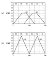
図の横軸は、ヘッドのノズルに対応し前述のとおり768ノズルのヘッドを用いている。ヘッドは、番号が768番のノズルから番号1番のノズルに向かって吐出されるため、同一印字領域への印字は、768番のノズルから128ノズルの単位で記録処理される。 インクはノズル番号が大きい側から順に吐出される。そのため、M1が選択されたインクが先に吐出され、M2が選択されたインクが後から吐出されることになる。その結果、記録媒体上では、図18(a)に示されているように、M1で吐出されたインクが先に記録媒体上に定着するため、M2で吐出されたインクは、M1で吐出されたインクの上層に定着する。 The horizontal axis in the figure corresponds to the nozzle of the head, and a 768 nozzle head is used as described above. Since the head is ejected from the No. 768 nozzle toward the No. 1 nozzle, printing in the same print area is recorded in units of 128 nozzles from the No. 768 nozzle. Ink is ejected in order from the larger nozzle number. Therefore, the ink with M1 selected is ejected first, and the ink with M2 selected is ejected later. As a result, on the recording medium, as shown in FIG. 18A, since the ink ejected in M1 is first fixed on the recording medium, the ink ejected in M2 is ejected in M1. Fix to the upper layer of the ink.
なお、M1におけるB1〜B4の各区間におけるマスクパターンは、M2におけるB3〜B6の各区間におけるマスクパターンと同一であることが望ましい。同一とした場合には、位置ずれ等を考慮しなければ、必ず図18(a)のようにM2で吐出されたインクは、M1で吐出されたインクの上層に定着する。そのため、より低い明度(より透過率の小さい)インクをM1で、より高い明度(より透過率の大きい)インクをM2で記録することにより図18(a)の状態で記録することが可能となることが分かる。そのため、従来生じていた図18(b)の状態となることによる、上層側のインクによる入射光の吸収による発色特性の低下を生じることはないことも分かる。 The mask pattern in each section of B1 to B4 in M1 is preferably the same as the mask pattern in each section of B3 to B6 in M2. If they are the same, the ink ejected by M2 is always fixed to the upper layer of the ink ejected by M1, as shown in FIG. Therefore, it is possible to record in the state shown in FIG. 18A by recording ink with lower lightness (lower transmittance) with M1 and ink with higher lightness (higher transmittance) with M2. I understand that. Therefore, it can also be seen that there is no deterioration in color development characteristics due to absorption of incident light by the upper layer ink due to the state shown in FIG.
<M1およびM2の各マスクへの各記録色の割り当て>
・グルーピング
以下では、CMYK4色インクで構成される場合における各記録色の記録順序の決定方法について説明する。つまり、4種類のインクの各々を前述のマスクM1、M2のそれぞれに割り当てる方法について説明する。以降、この処理をグルーピングと呼ぶ。
<Assignment of each recording color to each mask of M1 and M2>
-Grouping In the following, a method for determining the recording order of each recording color in the case of being composed of CMYK four color inks will be described. That is, a method for assigning each of the four types of ink to the masks M1 and M2 will be described. Hereinafter, this process is called grouping.
図19は、CMYK4色のインク構成の場合におけるグルーピングの設定を模式的に示す図である。また図20は、グルーピング処理のフォローチャートである。 FIG. 19 is a diagram schematically illustrating grouping settings in the case of an ink configuration of CMYK four colors. FIG. 20 is a follow chart of the grouping process.
ステップSP002は、明度順に並べるステップである。具体的には、図19のClass1に示されているように明度の明るい順にYインク(明度85)、Cインク(明度40)、Mインク(明度38)、Kインク(明度5)と並べる。
Step SP002 is a step of arranging in order of brightness. Specifically, as shown in
ステップSP003は、有彩色インクのグルーピングステップである。具体的には、図19のClass1からClass2へ推移しているように、隣り合う明度差を求めて明度差の小さいものからグルーピングを行い、グルーピングしたインクの明度の平均値を求める。例えば、図19のClass2では、明度の明るいインクから、Yインク(明度85)、C/Mインク(明度39)、Kインク(明度5)と3つのグループに絞り込まれる。
Step SP003 is a chromatic ink grouping step. Specifically, as shown in the transition from
ステップSP004は、無彩色インクのグルーピングステップである。後述する変形例1のようにGrayインクを含む場合は、Gray、Kインクにてグルーピングを行う。ここでは、グレイインクを含まないためスキップする。
Step SP004 is an achromatic ink grouping step. When Gray ink is included as in
ステップSP005は、全てのインクのグルーピングが終了したかどうかを判定する。Noの場合は、ステップSP003、SP004を繰り返す。Yesの場合、すなわち、全てのインクのグルーピングが終了した場合は、グルーピング処理を終了する。 In step SP005, it is determined whether or not all the inks have been grouped. In the case of No, steps SP003 and SP004 are repeated. In the case of Yes, that is, when the grouping of all the inks is finished, the grouping process is finished.
このような処理を行うことにより、YMCKの4色インクでは、Class3にてC/M/YインクのグループとKインクの2つのグループにグルーピングがなされる。
By performing such processing, the YMCK four-color ink is grouped into two groups of C / M / Y ink and K ink in
・マスクの割り当て
上述のグルーピング処理に基づくM1およびM2のマスク選択方法について以下に説明する。
Mask Assignment A mask selection method for M1 and M2 based on the above-described grouping process will be described below.
図21(a)は、有彩色領域でのマスク割り当てを例示的に示す図である。一方、図21(b)は無彩色領域でのマスク割り当てを例示的に示す図である。 FIG. 21A is a diagram exemplarily showing mask assignment in the chromatic color region. On the other hand, FIG. 21B is a diagram exemplarily showing mask assignment in the achromatic region.
図21(a)のY〜M色相では、YインクとMインクで混色される。この場合は、図19のClass1にてグルーピングされ相対的に明度の高いYインクがマスクパターンM2が選択され、相対的に明度の低いMインクはマスクパターンM1が選択される。以下同様に、M〜C色相では、相対的に明度の高いCインクがマスクパターンM2が選択され、相対的に明度の低いMインクはマスクパターンM1が選択される。C〜Y色相では、相対的に明度の高いYインクがマスクパターンM2が選択され、相対的に明度の低いCインクはマスクパターンM1が選択される。
In the Y to M hues in FIG. 21A, colors are mixed with Y ink and M ink. In this case, the mask pattern M2 is selected for the Y ink that is grouped in
図21(b)のWhiteからMid間では、C/M/Yインクの3色で構成されるため、図19のClass2にてグルーピングされる。つまり、相対的に明度の高いYインクがマスクパターンM2が選択され、相対的に明度の低いC/Mインクの2色はマスクパターンM1が選択される。また、MidからKの間では、C/M/Y/Kインクの4色で構成されるため、図19のClass3にてグルーピングされる。つまり、相対的に明度の高いC/M/Yインクの3色はマスクパターンM2が選択され、相対的に明度の低いKインクはマスクパターンM1が選択される。
Between White and Mid in FIG. 21B, since it is composed of three colors of C / M / Y ink, it is grouped in
このように構成することにより、混色されるインクの組み合わせに応じて、相対的に明度の高いグループに属するインクは、マスクパターンM2が選択されて相対的に後から記録される。一方、相対的に明度の低いグループに属するインクは、マスクパターンM1が選択されて相対的に先に記録される。顔料インクのような上乗せ系のインクでは、後から吐出されたインクは上層に定着する。そのため、相対的に明度の高い、すなわち、透過率の高いインクを上層に定着することにより、反対の相対的に明度の低い、すなわち透過率の低いインクを上層に定着する場合に比べ、高発色再現が可能となる。そして、色再現域の拡張を実現することができる。 With this configuration, ink belonging to a group having a relatively high brightness is recorded later after the mask pattern M2 is selected in accordance with the combination of inks to be mixed. On the other hand, the ink belonging to the group having relatively low brightness is recorded relatively first after the mask pattern M1 is selected. In an overlay ink such as a pigment ink, the ink ejected later is fixed on the upper layer. Therefore, by fixing an ink with relatively high lightness, that is, high transmittance, to the upper layer, compared with the case of fixing an ink with relatively low lightness, that is, low transmittance, to the upper layer, higher color development. Reproduction is possible. In addition, the color reproduction range can be expanded.
以上説明をしたとおり、第1実施形態によれば、相対的に明度(透過率)の低いインクに対し、相対的に明度の高いインクを上層(表面側)に記録(定着)することができる。そのため、発色特性の低下を低減可能とし従来に比較し色再現域を拡大することが出来る。 As described above, according to the first embodiment, ink having relatively high lightness (transmittance) can be recorded (fixed) on the upper layer (surface side) with respect to ink having relatively low lightness (transmittance). . For this reason, it is possible to reduce the deterioration of the color development characteristics, and it is possible to expand the color reproduction range as compared with the prior art.
(変形例1)
上述の第1実施形態では4色インクシステムについて説明を行った。しかし、それ5色以上のインクシステムに適用しても良い。ここでは、製品としても用いられている6色インクおよび11色インクを例にあげてそれぞれのグルーピング処理の例を示す。
(Modification 1)
In the first embodiment described above, the four-color ink system has been described. However, it may be applied to an ink system of five colors or more. Here, an example of each grouping process is shown by taking 6-color ink and 11-color ink used as products as examples.
なお、ここで、6色インクとは、Cインク、Mインク、Yインク、Kインクの基本4色インクにC、Mの顔料濃度が薄い淡Cインク(Lc)、淡Mインク(Lm)を加えた6色を意味する。また、11色インクとは、6色インクに、さらに、顔料濃度が薄いGrayインク(Gy)と顔料濃度がより薄い淡Grayインク(Lg)、特色Redインク、Greenインク、Blueインクを加えたものである。 Here, the six-color ink means the light C ink (Lc) and the light M ink (Lm) having low C and M pigment concentrations to the basic four color inks of C ink, M ink, Y ink, and K ink. Means 6 additional colors. The 11-color ink is obtained by adding a gray ink (Gy) with a light pigment density, a light gray ink (Lg) with a lighter pigment density, a special color red ink, a green ink, and a blue ink to 6 color inks. It is.
図22は、6色インクのグルーピングを例示的に示す図である。第1の実施形態における図20のフローチャートを用いて求めることができる。つまり、有彩色インクのグルーピング(ステップSP003)の段数がさらに大きくなっているのみである。 FIG. 22 is a diagram exemplarily illustrating grouping of six color inks. It can be obtained using the flowchart of FIG. 20 in the first embodiment. That is, the number of chromatic ink groupings (step SP003) is only increased.
図23は、11色インクのグルーピングを例示的に示す図である。同様に、図20のフローチャートを用いて求めることができる。つまり、有彩色インクのグルーピング(ステップSP003)および無彩色インクのグルーピング(ステップSP004)の段数がさらに大きくなっているのみである。 FIG. 23 is a diagram exemplarily illustrating grouping of 11 color inks. Similarly, it can be obtained using the flowchart of FIG. That is, the number of stages of chromatic ink grouping (step SP003) and achromatic ink grouping (step SP004) is only increased.
これらのグルーピングに基づき、第1の実施形態と同様に、マスクM1およびM2に割り当てることにより、発色特性の低下を低減可能とし従来に比較し色再現域を拡大することが出来る。 Based on these groupings, as in the first embodiment, by assigning to the masks M1 and M2, it is possible to reduce the deterioration of the color development characteristics and to expand the color reproduction range as compared with the conventional case.
(変形例2)
上述の第1実施形態では逆V字型の記録率分布を有するM1およびM2の2つマスクを用い説明した。しかし、記録率の分布は逆V字型に限定されない。また、マルチパス記録のパス数も4パスに限定されない。さらに、配置されるマスクの数も2つに限定されることは無い。
(Modification 2)
In the first embodiment described above, two masks M1 and M2 having an inverted V-shaped recording rate distribution have been described. However, the recording rate distribution is not limited to the inverted V shape. Also, the number of passes for multi-pass printing is not limited to four. Further, the number of masks to be arranged is not limited to two.
図24(a)は、同一領域を6回のパスで記録するマルチパス方式を用いた他の例を示す図である。第1実施形態と同様、先行する4パスと遅延する4パスの2種類のマスクを構成する。ただし、図17とは記録率分布が異なっている。 FIG. 24A is a diagram showing another example using a multi-pass method in which the same area is recorded with six passes. Similar to the first embodiment, two types of masks are configured, that is, the preceding four passes and the delayed four passes. However, the recording rate distribution is different from FIG.
図24(b)は、同一領域を6回のパスで記録するマルチパス方式を用いた他の例を示す図である。ただし、第1実施形態とは異なり、先行する3パスと遅延する3パスの2種類のマスクを構成する。 FIG. 24B is a diagram showing another example using a multi-pass method in which the same area is recorded with six passes. However, unlike the first embodiment, two types of masks are configured: the preceding three passes and the delayed three passes.
また、図25は、同一領域を6回のパスで記録するマルチパス方式を用いた他の例を示す図である。ただし、第1実施形態とは異なり、先行する4パスと遅延する4パスおよびさらに遅延する4パスの3種類のマスクを構成する。 FIG. 25 is a diagram showing another example using a multi-pass method in which the same area is recorded with six passes. However, unlike the first embodiment, three types of masks are configured: the preceding four paths, the four paths that are delayed, and the four paths that are further delayed.
このような構成とすることにより、さらに詳細な記録順序の制御が可能となる。なお、この例のように3種類のマスクを用いる場合は、グルーピング処理において、3つのグループに分割する。例えば、4色インクでは図19のClass2までを用いて3つのグループにグルーピングする。6色インクの場合は、図22のClass3までを用いて3つのグループにグルーピングする。さらに、11色インクの場合は、図23のClass5までを用いて3つのグループにグルーピングする。また、色分解処理(J0003)において2ビット値を用いてマスクの割り当てを指定する。
With such a configuration, it is possible to control the recording order in more detail. Note that when three types of masks are used as in this example, they are divided into three groups in the grouping process. For example, in the case of four-color ink, grouping into three groups is performed using
このように、パス数、マスクの記録率分布の形状、マスク数は、先行するマスクと遅延するマスクの少なくとも2つを構成するものであるならば、どのような形態でも良い。 Thus, the number of passes, the shape of the mask recording rate distribution, and the number of masks may be in any form as long as they constitute at least two of the preceding mask and the delayed mask.
(他の実施形態)
以上、本発明の実施形態について詳述したが、本発明は、複数の機器から構成されるシステムに適用しても良いし、また、一つの機器からなる装置に適用しても良い。
(Other embodiments)
Although the embodiments of the present invention have been described in detail above, the present invention may be applied to a system constituted by a plurality of devices or may be applied to an apparatus constituted by one device.
なお、本発明は、前述した実施形態の機能を実現するプログラムを、システム或いは装置に直接或いは遠隔から供給し、そのシステム或いは装置が、供給されたプログラムコードを読み出して実行することによっても達成される。従って、本発明の機能処理をコンピュータで実現するために、コンピュータにインストールされるプログラムコード自体も本発明の技術的範囲に含まれる。 The present invention can also be achieved by supplying a program that realizes the functions of the above-described embodiments directly or remotely to a system or apparatus, and the system or apparatus reads and executes the supplied program code. The Accordingly, the program code itself installed in the computer in order to realize the functional processing of the present invention by the computer is also included in the technical scope of the present invention.
その場合、プログラムの機能を有していれば、オブジェクトコード、インタプリタにより実行されるプログラム、OSに供給するスクリプトデータ等、プログラムの形態を問わない。 In this case, the program may be in any form as long as it has a program function, such as an object code, a program executed by an interpreter, or script data supplied to the OS.
プログラムを供給するための記録媒体としては、例えば、フロッピー(登録商標)ディスク、ハードディスク、光ディスク(CD、DVD)、光磁気ディスク、磁気テープ、不揮発性のメモリカード、ROMなどがある。 Examples of the recording medium for supplying the program include a floppy (registered trademark) disk, a hard disk, an optical disk (CD, DVD), a magneto-optical disk, a magnetic tape, a nonvolatile memory card, and a ROM.
また、コンピュータが、読み出したプログラムを実行することによって、前述した実施形態の機能が実現される。その他、そのプログラムの指示に基づき、コンピュータ上で稼動しているOSなどが、実際の処理の一部または全部を行い、その処理によっても前述した実施形態の機能が実現され得る。 Further, the functions of the above-described embodiments are realized by the computer executing the read program. In addition, based on the instructions of the program, an OS or the like running on the computer performs part or all of the actual processing, and the functions of the above-described embodiments can also be realized by the processing.
さらに、記録媒体から読み出されたプログラムが、コンピュータに挿入された機能拡張ボードやコンピュータに接続された機能拡張ユニットに備わるメモリに書き込まれる。その後、そのプログラムの指示に基づき、その機能拡張ボードや機能拡張ユニットに備わるCPUなどが実際の処理の一部または全部を行い、その処理によっても前述した実施形態の機能が実現される。 Further, the program read from the recording medium is written in a memory provided in a function expansion board inserted into the computer or a function expansion unit connected to the computer. Thereafter, the CPU of the function expansion board or function expansion unit performs part or all of the actual processing based on the instructions of the program, and the functions of the above-described embodiments are realized by the processing.
J0001 アプリケーション
J0002 カラーマッチング処理
J0003 色分解処理
J0004 γ補正
J0005 ハーフトーニング
J0006 印刷データの作成処理
J0007 ドット配置パターン化処理
J0008 マスクデータ変換処理
J0009 ヘッド駆動回路
J0010 記録へッド
B0002 累積誤差演算部
B0003 端子
B0004 量子化部
B0005 誤差演算部
B0006 誤差拡散部
B0007 累積誤差メモリ
B0008 出力端子
B0015 画像の左上端に位置する画素
B0016 画像の右下端に位置する画素
B0017 イエロー画像データ
B0018 レッド画像データ
B0019 量子化後のイエローの画像データ
B0020 量子化後のレッドの画像データ
B0021 レベル0の画素
B0022 レベル32の画素
B0023 レベル96の画素
B0024 レベル128の画素
P0001 記録ヘッド
P0002 マスクパターン
P0003 第1記録走査での記録画像
P0004 第2記録走査での記録画像
P0005 第3記録走査での記録画像
P0006 第4記録走査での記録画像
H1001 記録ヘッド
H1900 インクタンク
H2000 シアン(C)ノズル列
H2100 マゼンタ(M)ノズル列
H2200 イエロー(Y)ノズル列
H2300 ブラック(K)ノズル列
J0001 Application J0002 Color matching processing J0003 Color separation processing J0004 γ correction J0005 Halftoning J0006 Print data creation processing J0007 Dot arrangement patterning processing J0008 Mask data conversion processing J0009 Head drive circuit J0010 Recording head B0002 Cumulative error calculation section B0003 Terminal B0004 Quantization unit B0005 Error calculation unit B0006 Error diffusion unit B0007 Cumulative error memory B0008 Output terminal B0015 Pixel located at the upper left corner of the image B0016 Pixel located at the lower right corner of the image B0017 Yellow image data B0018 Red image data B0019 Yellow after quantization Image data B0020 Quantized red image
Claims (8)
前記同一画像領域の色を表し、前記複数の色材の各々に対応する複数の色材データを入力する入力手段と、
前記複数の色材データのうち記録を示す色材データに対応する色材の組合せに基づき、前記複数の色材データの各々を、それぞれの色材に対応する記録素子列を構成する複数の記録素子群に割り当てる割当手段と、
前記割り当てられた色材データを用いて前記画像領域に対して前記記録ヘッドを複数回記録走査させる走査手段と、
を備え、
前記割当手段は、前記複数の記録素子群のうち、記録媒体に先行して記録する記録素子群に対して前記組合せのうち相対的に低明度の色材に対応する色材データを割り当て、前記先行して記録する記録素子群よりも遅延して記録する記録素子群に対して前記組合せのうち相対的に高明度の色材に対応する色材データを割り当てることを特徴とする画像形成装置。 A recording head comprising a plurality of recording elements arranged in the transport direction of the recording medium, each of which includes a plurality of coloring materials each containing a pigment, on the recording medium. An image forming apparatus that forms an image by performing recording scanning a plurality of times in a direction orthogonal to the transport direction in the same image area,
An input means for representing a color of the same image area and inputting a plurality of color material data corresponding to each of the plurality of color materials;
Based on the combination of the color materials that corresponds to the color material data indicating the recording of the plurality of color material data, each of the plurality of color material data, a plurality of which constitute the printing element array corresponding to each color material and assigning means for assigning the recording element groups,
Scanning means for recording and scanning the recording head a plurality of times with respect to the image area using the allocated color material data;
With
The assigning means assigns color material data corresponding to a relatively light color material of the combination to the recording element group that records the recording element prior to the recording medium among the plurality of recording element groups, An image forming apparatus, wherein color material data corresponding to a color material having a relatively high brightness among the combinations is assigned to a recording element group to be recorded later than a recording element group to be recorded in advance.
前記割当手段は、前記複数のマスクパターンを用いて前記複数の記録素子群の各々に前記複数の色材データの各々を割り当てることを特徴とする請求項1乃至3の何れか一項に記載の画像形成装置。 Further comprising a storage means corresponding to each of the plurality of printing element groups, each of which stores a plurality of mask patterns to allocate a recording element of the recording element groups in each of the plurality of times recording scan,
The assigning unit according to any one of claims 1 to 3, wherein the assigning each of the plurality of color material data to each of the plurality of printing element groups by using a plurality of mask patterns Image forming apparatus.
前記割当手段は、前記組合せに含まれる色材に対応する色材データを、前記グルーピング手段によるグルーピング結果に基づいて前記複数の記録素子群に割り当てることを特徴とする請求項1乃至5の何れか一項に記載の画像形成装置。 The assigning means includes grouping means for grouping the plurality of color materials based on the brightness of each of the plurality of color materials.
The assigning unit, a color material data corresponding to the color material contained in the combination, according to claim 1 to 5, characterized in that to assign the plurality of printing element groups, based on the grouping result by the grouping unit The image forming apparatus according to any one of the above.
前記同一画像領域の色を表し、前記複数の色材の各々に対応する複数の色材データを入力する入力工程と、
前記複数の色材データのうち記録を示す色材データに対応する色材の組合せに基づき、前記複数の色材データの各々を、それぞれの色材に対応する記録素子列を構成する複数の記録素子群に割り当てる割当工程と、
前記割り当てられた色材データを用いて前記画像領域に対して前記記録ヘッドを複数回記録走査させる走査工程と、
を備え、
前記割当工程では、前記複数の記録素子群のうち、記録媒体に先行して記録する記録素子群に対して前記組合せのうち相対的に低明度の色材に対応する色材データを割り当て、前記先行して記録する記録素子群よりも遅延して記録する記録素子群に対して前記組合せのうち相対的に高明度の色材に対応する色材データを割り当てることを特徴とする画像形成装置の制御方法。 A recording head comprising a plurality of recording elements arranged in the transport direction of the recording medium, each of which includes a plurality of coloring materials each containing a pigment, on the recording medium. A method of controlling an image forming apparatus that forms an image by performing scanning scanning a plurality of times in a direction orthogonal to the transport direction in the same image area,
An input step that represents the color of the same image area and inputs a plurality of color material data corresponding to each of the plurality of color materials;
Based on the combination of the color materials that corresponds to the color material data indicating the recording of the plurality of color material data, each of the plurality of color material data, a plurality of which constitute the printing element array corresponding to each color material an assignment step of assigning the recording element groups,
A scanning step of recording and scanning the recording head a plurality of times with respect to the image area using the allocated color material data;
With
In the assigning step, among the plurality of recording element groups, color material data corresponding to a color material having a relatively low lightness among the combinations is assigned to a recording element group to be recorded prior to a recording medium, An image forming apparatus characterized in that color material data corresponding to a color material having a relatively high lightness among the combinations is assigned to a recording element group to be recorded later than a recording element group to be recorded in advance. Control method.
Priority Applications (2)
| Application Number | Priority Date | Filing Date | Title |
|---|---|---|---|
| JP2006353176A JP5072349B2 (en) | 2006-12-27 | 2006-12-27 | Image forming apparatus and control method thereof |
| US11/960,151 US20080158281A1 (en) | 2006-12-27 | 2007-12-19 | Image forming apparatus and control method thereof |
Applications Claiming Priority (1)
| Application Number | Priority Date | Filing Date | Title |
|---|---|---|---|
| JP2006353176A JP5072349B2 (en) | 2006-12-27 | 2006-12-27 | Image forming apparatus and control method thereof |
Publications (3)
| Publication Number | Publication Date |
|---|---|
| JP2008162094A JP2008162094A (en) | 2008-07-17 |
| JP2008162094A5 JP2008162094A5 (en) | 2010-04-02 |
| JP5072349B2 true JP5072349B2 (en) | 2012-11-14 |
Family
ID=39583267
Family Applications (1)
| Application Number | Title | Priority Date | Filing Date |
|---|---|---|---|
| JP2006353176A Active JP5072349B2 (en) | 2006-12-27 | 2006-12-27 | Image forming apparatus and control method thereof |
Country Status (2)
| Country | Link |
|---|---|
| US (1) | US20080158281A1 (en) |
| JP (1) | JP5072349B2 (en) |
Families Citing this family (9)
| Publication number | Priority date | Publication date | Assignee | Title |
|---|---|---|---|---|
| US8088207B2 (en) * | 2009-08-28 | 2012-01-03 | Clear Lam Packaging, Inc. | Eleven-color printing ink set and method of use |
| JP5014475B2 (en) | 2010-07-28 | 2012-08-29 | キヤノン株式会社 | Image processing apparatus and image processing method |
| JP5634154B2 (en) | 2010-07-28 | 2014-12-03 | キヤノン株式会社 | Image processing apparatus and image processing method |
| JP5780737B2 (en) | 2010-10-15 | 2015-09-16 | キヤノン株式会社 | Inkjet recording apparatus and inkjet recording method |
| JP5748522B2 (en) | 2011-03-29 | 2015-07-15 | キヤノン株式会社 | Inkjet recording apparatus and inkjet recording method |
| JP5910335B2 (en) * | 2012-06-11 | 2016-04-27 | セイコーエプソン株式会社 | Printing apparatus and printing method |
| WO2015022274A1 (en) * | 2013-08-12 | 2015-02-19 | Thomson Licensing | Image processing method and device, image restitution method and device, and corresponding computer program and system |
| JP2017030151A (en) * | 2015-07-28 | 2017-02-09 | 株式会社沖データ | Image processing device |
| JP6938978B2 (en) * | 2017-03-14 | 2021-09-22 | 株式会社リコー | Image forming device, ink ejection method, liquid ejection device |
Family Cites Families (6)
| Publication number | Priority date | Publication date | Assignee | Title |
|---|---|---|---|---|
| SG44724A1 (en) * | 1989-01-28 | 1997-12-19 | Canon Kk | Ink jet recording method and color ink jet recording device for practising the same |
| US6273550B1 (en) * | 2000-02-23 | 2001-08-14 | Mutoh Industries Inc. | Inkjet printer capable of minimizing chromatic variation in adjacent print swaths when printing color images in bidirectional mode |
| JP4817520B2 (en) * | 2001-04-02 | 2011-11-16 | キヤノン株式会社 | Inkjet recording apparatus and inkjet recording method |
| US6783203B2 (en) * | 2001-05-11 | 2004-08-31 | Seiko Epson Corporation | Printing with multiple pixels as unit of gradation reproduction |
| JP2003266663A (en) * | 2002-03-14 | 2003-09-24 | Konica Corp | Image recording method and ink jet printer |
| JP4261980B2 (en) * | 2003-05-16 | 2009-05-13 | キヤノン株式会社 | Image forming method |
-
2006
- 2006-12-27 JP JP2006353176A patent/JP5072349B2/en active Active
-
2007
- 2007-12-19 US US11/960,151 patent/US20080158281A1/en not_active Abandoned
Also Published As
| Publication number | Publication date |
|---|---|
| JP2008162094A (en) | 2008-07-17 |
| US20080158281A1 (en) | 2008-07-03 |
Similar Documents
| Publication | Publication Date | Title |
|---|---|---|
| JP5072349B2 (en) | Image forming apparatus and control method thereof | |
| JP5347300B2 (en) | Printing device | |
| US8240795B2 (en) | Printing method and printing apparatus | |
| JP4502362B2 (en) | Inkjet recording method, inkjet recording system, inkjet recording apparatus, and control program | |
| JP4486280B2 (en) | Printing apparatus, printing method, recording medium recording program therefor, and program | |
| US6659583B2 (en) | Printing involving halftone reproduction with different density inks in pixel block units | |
| JP4385626B2 (en) | Image processing apparatus, image processing method, and image processing program | |
| JP4208652B2 (en) | Inkjet recording apparatus and inkjet recording method | |
| JP4560193B2 (en) | Data processing method and data processing apparatus | |
| JP5311980B2 (en) | Inkjet recording device | |
| JP3981480B2 (en) | Printing apparatus and recording medium | |
| JP2006001051A (en) | Inkjet recording method and inkjet recorder | |
| JP4497597B2 (en) | Image processing apparatus and image processing method | |
| JP2010012625A (en) | Inkjet recording device and control method and program therefor | |
| JP5645686B2 (en) | Recording control apparatus, recording system, and recording method | |
| JP4827674B2 (en) | Recording apparatus and recording method | |
| JPH09327936A (en) | Printer device and printer head | |
| JP5072350B2 (en) | Image forming apparatus and control method thereof | |
| JP5084159B2 (en) | Inkjet recording apparatus, inkjet recording method, and program | |
| JP2005342962A (en) | Device and method for processing image | |
| JP5748522B2 (en) | Inkjet recording apparatus and inkjet recording method | |
| JP2012111183A (en) | Recording apparatus, and recording method | |
| JP2012153119A (en) | Inkjet printing apparatus, and inkjet printing method | |
| JP2005161630A (en) | Inkjet recording system and inkjet recording method | |
| JP2006224616A (en) | Recording method and recording system |
Legal Events
| Date | Code | Title | Description |
|---|---|---|---|
| A621 | Written request for application examination |
Free format text: JAPANESE INTERMEDIATE CODE: A621 Effective date: 20091211 |
|
| A521 | Written amendment |
Free format text: JAPANESE INTERMEDIATE CODE: A523 Effective date: 20100215 |
|
| A977 | Report on retrieval |
Free format text: JAPANESE INTERMEDIATE CODE: A971007 Effective date: 20111024 |
|
| A131 | Notification of reasons for refusal |
Free format text: JAPANESE INTERMEDIATE CODE: A131 Effective date: 20111028 |
|
| A521 | Written amendment |
Free format text: JAPANESE INTERMEDIATE CODE: A523 Effective date: 20111222 |
|
| TRDD | Decision of grant or rejection written | ||
| A01 | Written decision to grant a patent or to grant a registration (utility model) |
Free format text: JAPANESE INTERMEDIATE CODE: A01 Effective date: 20120817 |
|
| A01 | Written decision to grant a patent or to grant a registration (utility model) |
Free format text: JAPANESE INTERMEDIATE CODE: A01 |
|
| A61 | First payment of annual fees (during grant procedure) |
Free format text: JAPANESE INTERMEDIATE CODE: A61 Effective date: 20120821 |
|
| R151 | Written notification of patent or utility model registration |
Ref document number: 5072349 Country of ref document: JP Free format text: JAPANESE INTERMEDIATE CODE: R151 |
|
| FPAY | Renewal fee payment (event date is renewal date of database) |
Free format text: PAYMENT UNTIL: 20150831 Year of fee payment: 3 |