JP4931164B2 - Mask pattern manufacturing method - Google Patents
Mask pattern manufacturing method Download PDFInfo
- Publication number
- JP4931164B2 JP4931164B2 JP2001215789A JP2001215789A JP4931164B2 JP 4931164 B2 JP4931164 B2 JP 4931164B2 JP 2001215789 A JP2001215789 A JP 2001215789A JP 2001215789 A JP2001215789 A JP 2001215789A JP 4931164 B2 JP4931164 B2 JP 4931164B2
- Authority
- JP
- Japan
- Prior art keywords
- recording
- mask
- data
- pass
- Prior art date
- Legal status (The legal status is an assumption and is not a legal conclusion. Google has not performed a legal analysis and makes no representation as to the accuracy of the status listed.)
- Expired - Fee Related
Links
- 238000004519 manufacturing process Methods 0.000 title claims description 15
- 238000000034 method Methods 0.000 claims description 142
- 238000007639 printing Methods 0.000 description 185
- 239000000976 ink Substances 0.000 description 138
- 239000000872 buffer Substances 0.000 description 104
- 210000003128 head Anatomy 0.000 description 68
- 238000010586 diagram Methods 0.000 description 47
- 238000012545 processing Methods 0.000 description 44
- 230000000694 effects Effects 0.000 description 43
- 230000002457 bidirectional effect Effects 0.000 description 41
- 230000008569 process Effects 0.000 description 37
- 239000004381 Choline salt Substances 0.000 description 28
- 238000001514 detection method Methods 0.000 description 25
- 239000000758 substrate Substances 0.000 description 24
- 230000002829 reductive effect Effects 0.000 description 23
- 230000015572 biosynthetic process Effects 0.000 description 22
- 238000005755 formation reaction Methods 0.000 description 22
- 230000006870 function Effects 0.000 description 19
- 239000003086 colorant Substances 0.000 description 18
- 238000003860 storage Methods 0.000 description 16
- 238000011161 development Methods 0.000 description 12
- 230000002411 adverse Effects 0.000 description 9
- 230000001965 increasing effect Effects 0.000 description 9
- 230000007246 mechanism Effects 0.000 description 8
- 238000004364 calculation method Methods 0.000 description 7
- 238000003491 array Methods 0.000 description 6
- 230000005540 biological transmission Effects 0.000 description 6
- 230000007423 decrease Effects 0.000 description 6
- 238000012546 transfer Methods 0.000 description 6
- 230000000295 complement effect Effects 0.000 description 5
- 230000002349 favourable effect Effects 0.000 description 5
- 238000007641 inkjet printing Methods 0.000 description 5
- 239000007788 liquid Substances 0.000 description 5
- 238000011084 recovery Methods 0.000 description 5
- 230000003252 repetitive effect Effects 0.000 description 5
- 241000282414 Homo sapiens Species 0.000 description 4
- 230000008859 change Effects 0.000 description 4
- 239000000975 dye Substances 0.000 description 4
- 238000009429 electrical wiring Methods 0.000 description 4
- 238000007667 floating Methods 0.000 description 4
- 230000000737 periodic effect Effects 0.000 description 4
- 238000003825 pressing Methods 0.000 description 4
- 230000000007 visual effect Effects 0.000 description 4
- 230000006837 decompression Effects 0.000 description 3
- 238000006073 displacement reaction Methods 0.000 description 3
- 238000009826 distribution Methods 0.000 description 3
- 238000002474 experimental method Methods 0.000 description 3
- 238000012986 modification Methods 0.000 description 3
- 230000004048 modification Effects 0.000 description 3
- 238000013139 quantization Methods 0.000 description 3
- 230000007175 bidirectional communication Effects 0.000 description 2
- 230000015556 catabolic process Effects 0.000 description 2
- 230000006854 communication Effects 0.000 description 2
- 238000004891 communication Methods 0.000 description 2
- 238000007906 compression Methods 0.000 description 2
- 230000006835 compression Effects 0.000 description 2
- 238000013144 data compression Methods 0.000 description 2
- 238000006731 degradation reaction Methods 0.000 description 2
- 230000006866 deterioration Effects 0.000 description 2
- 239000006185 dispersion Substances 0.000 description 2
- 238000005516 engineering process Methods 0.000 description 2
- 238000011156 evaluation Methods 0.000 description 2
- 238000012840 feeding operation Methods 0.000 description 2
- 238000005286 illumination Methods 0.000 description 2
- 230000006872 improvement Effects 0.000 description 2
- 238000003780 insertion Methods 0.000 description 2
- 230000037431 insertion Effects 0.000 description 2
- 239000011159 matrix material Substances 0.000 description 2
- 239000002184 metal Substances 0.000 description 2
- 229910052751 metal Inorganic materials 0.000 description 2
- 230000003287 optical effect Effects 0.000 description 2
- 230000036961 partial effect Effects 0.000 description 2
- 239000000049 pigment Substances 0.000 description 2
- 239000002985 plastic film Substances 0.000 description 2
- 230000002265 prevention Effects 0.000 description 2
- 238000001454 recorded image Methods 0.000 description 2
- 230000009467 reduction Effects 0.000 description 2
- 230000002441 reversible effect Effects 0.000 description 2
- 230000001360 synchronised effect Effects 0.000 description 2
- 238000012935 Averaging Methods 0.000 description 1
- 241000282412 Homo Species 0.000 description 1
- 101000619564 Homo sapiens Putative testis-specific prion protein Proteins 0.000 description 1
- 102100022208 Putative testis-specific prion protein Human genes 0.000 description 1
- 238000010521 absorption reaction Methods 0.000 description 1
- 238000013459 approach Methods 0.000 description 1
- 230000008901 benefit Effects 0.000 description 1
- 230000004397 blinking Effects 0.000 description 1
- 238000009835 boiling Methods 0.000 description 1
- 239000000919 ceramic Substances 0.000 description 1
- 230000000052 comparative effect Effects 0.000 description 1
- 239000000470 constituent Substances 0.000 description 1
- 238000010276 construction Methods 0.000 description 1
- 238000007796 conventional method Methods 0.000 description 1
- 230000007547 defect Effects 0.000 description 1
- 230000001627 detrimental effect Effects 0.000 description 1
- 238000009792 diffusion process Methods 0.000 description 1
- 230000003292 diminished effect Effects 0.000 description 1
- 239000000428 dust Substances 0.000 description 1
- 238000003708 edge detection Methods 0.000 description 1
- 230000002708 enhancing effect Effects 0.000 description 1
- 238000001704 evaporation Methods 0.000 description 1
- 239000004744 fabric Substances 0.000 description 1
- 239000011521 glass Substances 0.000 description 1
- 239000010985 leather Substances 0.000 description 1
- 230000000873 masking effect Effects 0.000 description 1
- 230000000414 obstructive effect Effects 0.000 description 1
- 230000010355 oscillation Effects 0.000 description 1
- 239000002245 particle Substances 0.000 description 1
- 238000000206 photolithography Methods 0.000 description 1
- 229920006255 plastic film Polymers 0.000 description 1
- 230000004044 response Effects 0.000 description 1
- 239000004065 semiconductor Substances 0.000 description 1
- 238000000926 separation method Methods 0.000 description 1
- 229910052709 silver Inorganic materials 0.000 description 1
- 239000004332 silver Substances 0.000 description 1
- -1 silver halide Chemical class 0.000 description 1
- GGCZERPQGJTIQP-UHFFFAOYSA-N sodium;9,10-dioxoanthracene-2-sulfonic acid Chemical compound [Na+].C1=CC=C2C(=O)C3=CC(S(=O)(=O)O)=CC=C3C(=O)C2=C1 GGCZERPQGJTIQP-UHFFFAOYSA-N 0.000 description 1
- 238000007711 solidification Methods 0.000 description 1
- 230000008023 solidification Effects 0.000 description 1
- 230000007480 spreading Effects 0.000 description 1
- 238000003892 spreading Methods 0.000 description 1
- 230000001960 triggered effect Effects 0.000 description 1
- 238000003466 welding Methods 0.000 description 1
- 239000002023 wood Substances 0.000 description 1
Images


Classifications
-
- G—PHYSICS
- G06—COMPUTING; CALCULATING OR COUNTING
- G06K—GRAPHICAL DATA READING; PRESENTATION OF DATA; RECORD CARRIERS; HANDLING RECORD CARRIERS
- G06K15/00—Arrangements for producing a permanent visual presentation of the output data, e.g. computer output printers
- G06K15/02—Arrangements for producing a permanent visual presentation of the output data, e.g. computer output printers using printers
- G06K15/10—Arrangements for producing a permanent visual presentation of the output data, e.g. computer output printers using printers by matrix printers
- G06K15/102—Arrangements for producing a permanent visual presentation of the output data, e.g. computer output printers using printers by matrix printers using ink jet print heads
- G06K15/105—Multipass or interlaced printing
- G06K15/107—Mask selection
Landscapes
- Physics & Mathematics (AREA)
- Engineering & Computer Science (AREA)
- Mathematical Physics (AREA)
- General Engineering & Computer Science (AREA)
- General Physics & Mathematics (AREA)
- Theoretical Computer Science (AREA)
- Ink Jet (AREA)
- Particle Formation And Scattering Control In Inkjet Printers (AREA)
- Fax Reproducing Arrangements (AREA)
- Color Image Communication Systems (AREA)
Description
【0001】
【発明の属する技術分野】
本発明は、インクジェット方式によるプリント装置に適用されるマスクパターンの製造方法に関するものである。さらに詳しくは、本発明は、所謂シリアル型のカラーインクジェットプリント装置にあって、特に双方向プリント等、同一画像領域に対しては相補的な関係にある画素配列に従った複数回の主走査を適用しつつ分割プリントを行う場合に問題となる画像のざらつきや、カラーインクの打ち込み順に起因する色むらを無くすために適用されるマスクパターンの製造方法に関するものである。なお、本発明は、一般的なプリント装置のほか、複写機、通信システムを有するファクシミリ,プリント部を有するワードプロセッサ等の装置、さらには、各種処理装置と複合的に組み合わされた産業用記録装置に適用することができる。
【0002】
【従来の技術】
プリント部たる記録ヘッドをプリント媒体上で走査させながらプリント動作を実行する所謂シリアル走査型の画像記録装置は、さまざまな画像形成に適用されている。特にインクジェット方式によるものは、近年高解像度化やカラー化が進み、画像品位が目覚しく向上したことから、急速に普及してきている。このような装置では、インクを例えば滴として吐出する吐出口を集積配置してなる所謂マルチノズルヘッドが用いられているが、現在では吐出口の集積密度を高め、かつ1ドット当たりのインク吐出量を小さくすることで更なる高解像度の画像形成が可能となってきている。一方、より銀塩写真に迫る画質を実現するために、基本となる4色のインク(シアン、マゼンタ、イエロー、ブラックの各色インク)の他に、これらの濃度を低くした淡インクも同時に用いて記録を行うものなど、多彩な技術が展開されている。また、この高画質化が進むにつれて懸念されていた記録速度の低下についても、プリント素子数の増大や駆動周波数の向上、更には双方向プリントのような技術を採用することで対応が図られ、良好なスループットが得られるようになってきている。
【0003】
図45は上記マルチノズルを用いてプリントを行うプリンタの一般的構成を模式的に示す。この図において、1901は例えばブラック(K)、シアン(C)、マゼンタ(M)およびイエロー(Y)の4色のインクに対応して設けたヘッドカートリッジであり、それぞれのヘッドカートリッジ1901はそれらのいずれかの色のインクを充填したインクタンク1902Tと、そのインクタンクから供給されるインクをプリント媒体上に吐出可能な吐出口を多数配列してなるヘッド部1902Hとから構成されている。
【0004】
図46はこのヘッド部1902Hの吐出口の配列態様を示すために、ヘッド部1902Hをz方向から見た状態を簡易的に示したものである。2001は吐出口であり、図示の例では1列に配列されている。
【0005】
再び図45を参照するに、1903は紙送りローラ(フィードローラ)であり、補助ローラ1904と協働してプリント媒体(記録紙)1907を挟持しつつ図の矢印方向に回転し、記録紙1907を随時y方向に搬送する。また、1905は記録紙1907を挟持しながら被プリント位置に向けて送給する一対の給紙ローラであり、ローラ1903および1904との間で記録紙1907を平坦に保持する機能も果たす。
【0006】
1906は4つのヘッドカートリッジ1901を支持し、プリント動作に際してこれらを主走査方向に移動させるためのキャリッジであり、プリントを実行しないとき、あるいはヘッド部1902Hのインク吐出性能を良好に保持するための回復動作を行うときには、図の破線で示した位置(ホームポジション)hに設定される。
【0007】
プリント開始前にホームポジションhに設定されているキャリッジ1906は、プリント開始命令の入来に応じてx方向に移動を開始し、ヘッド部1902Hに設けられた複数(n個)の吐出口からプリントデータに応じてインクを吐出して、吐出口配列範囲に対応した幅Dのプリントを行って行く。そして、記録紙1907のx方向端部までプリント動作が終了すると、片方向プリントの場合にはキャリッジ1906はホームポジションhに復帰し、再びx方向に向けてプリント動作を行う。また、双方向プリントであればホームポジションhに向かう−x方向の移動時にもプリント動作を行う。いずれにせよ、一方向へ向かう1回のプリント動作(1スキャン)が終了してから次回のプリント動作が開始される前に、紙送りローラ1903が図の矢印方向に所定量回転することで、所定量(吐出口配列幅分)だけy方向に記録紙1907が搬送される。これらのように、1スキャンのプリント動作と所定幅の記録紙搬送とを繰り返すことにより、記録紙1枚分のデータのプリントが完成する。
【0008】
さて、モノクロームプリンタとして文字,数字,記号などのキャラクタのみを記録するものと異なり、カラーイメージ画像をプリントするに当たっては、発色性、階調性、一様性など様々な要素が要求される。特に一様性に関しては、多数のノズル(本明細書では、特にことわらない限り吐出口ないしこれに連通する液路およびインク吐出に利用されるエネルギを発生する素子を総括して言うものとする)を集積配置してなるマルチノズルヘッドの製作工程時に生じる僅かなノズル単位のばらつきが、プリント動作時において各ノズルのインク吐出量やインク吐出方向の向きに影響を及ぼし、最終的にはプリント画像の濃度むらとして画像品位を低下させる。
【0009】
図47〜図49を用いてその具体例および対策を説明する。図47(a)において、3001はマルチノズルヘッドであり、図46に示したものと同様の構成であるが、ここでは簡単のため8個のノズル3002によって構成されているものとする。3003はノズル3002によって吐出されたインクドロップレットであり、この図のように揃った吐出量で、揃った方向にインクが吐出されるのが理想である。このような吐出が行われれば、図47(b)に示すようにプリント媒体上に揃った大きさのインクドットが着弾し、全体的にも濃度むらの無い一様な濃度分布が得られる(図47(c))。
【0010】
しかし実際には、ノズル1つ1つにそれぞればらつきがあり、そのまま上記と同じようにプリントを行ってしまうと、図48(a)に示したようにそれぞれのノズルより吐出されるインクドロップの大きさおよび向きにばらつきが生じ、紙面上においては図48(b)に示すようになる。この図によれば、ヘッド主走査方向に対し、周期的に白紙の部分が存在したり、また逆に必要以上にドットが重なり合ったり、あるいはこの図の中央部分に見られるような白筋が発生したりしている。この状態で記録されたドットの集まりはノズル並び方向に対し、図48(c)図に示した濃度分布となり、結果的には、通常人間の目で見たときに、これらの現象が濃度むらとして感知されるのである。
【0011】
そこでこの濃度むら対策として次のような方法が提案されている。
【0012】
図49によりその方法を説明する。ここでは図47および図48で示したのと同様の領域についてのプリントを完成させるのにヘッド3001を図49の(a)に示すように3回スキャンしているが、図中縦方向8画素の半分である4画素を単位とする領域は2回の記録走査(パス)で完成している。この場合ヘッド3001の8ノズルは、図中上半分の4ノズルと、下半分の4ノズルとのグループに分けられ、1ノズルが1回のスキャンで形成するドットは、画像データをある所定の画像データ配列に従って約半分に間引いたものである。そして2回目のスキャン時に残りの半分の画像データへドットを埋め込み、4画素単位領域の記録を完成させる。以上のような記録法は分割記録法あるいはマルチパス記録法と称される。この記録方法を実施すれば、図48で用いた記録ヘッドと等しいものを使用しても、各ノズル固有のプリント画像への影響が半減されるので、プリントされた画像は図49(b)のようになり、図48(b)に見られたようなるような白すじや黒すじが余り目立たなくなる。従って濃度むらも図49(c)に示すように図48(c)の場合と比べかなり緩和される。
【0013】
以上では同一記録領域に対し、2回の記録走査で画像を完成させる構成を説明したが、マルチパス記録はパス数が多いほど画像品位は向上する。しかし、一方でプリント時間は長くなるといういわばトレードオフの関係がある。
【0014】
このような状況下、画像をいかに迅速かつ美しく出力するかということを目的に、既に様々な提案がなされている。特開平5−31922号公報では、ディザ法などの面積階調法による画像データ配列を、これと非同期のドット配列を持つ間引きパターンを適用してマスクとするという内容が開示されている。ここでは、所定のディザパターンに同調しないマスクパターンを用いることにより、複数パスでのデータ記録率をなるべく等分にし、滑らかな画像を得ようとしているものである。しかしこの方法では、目的とされた所定のディザパターンについては対応できるものの、すべての2値化方法に等しく対応するのは困難であった。
【0015】
また、特開平7−52390号公報は、ランダム性を持たせたマスタパターンを用いる記録方法を開示している。これによればすべての2値化法に対し、分割記録が主眼とするつなぎ部やノズルばらつきによる画像むらを改善することができる。
【0016】
しかし膨大な容量のメモリを具えない限りプリント媒体全面など広い範囲に適用されるマスクを構成することはできず、実際には所定サイズのマスクをプリント媒体全面に対し繰り返し適用するのが一般的である。一方、プリント装置では記録走査毎に機械的な誤差が多少とも生じるので、記録走査間でドット形成位置に若干のずれが生じる。この若干のずれは各記録走査に適用されるマスクの形状(模様)を形成画像上に浮き立たせてしまい、所定サイズのマスク模様が繰り返し現れるという画像品位の低下をもたらすことがあった。そこで、上記所定サイズを持つランダムマスクの適用開始位置を記録走査毎にずらしたり、ずらし量をランダムに変化させたりすることで、見かけ上ランダムマスクの周期的繰り返しを起こさせないようにするような構成が提案されている(特開平7−125311号公報)。これによると、上記所定サイズの模様が発生したとしても、これが規則的に配列されないので、画像品位の低下が視覚的に認識されにくくなるのである。
【0017】
ところで、上記に示した分割記録では、分割数が多くなるにつれ、1紙面分を記録するタイムコストが大きくかかり、記録のスループットが低下するという問題があった。これに対しては、キャリッジの往復走査の過程での記録(双方向プリント)を行うことで記録時間の短縮を図ることが考えられる。これによれば、従来1方向の記録走査が行われた後に、何の記録を行うことも無くホームポジションに復帰させるキャリッジ走査が全て省かれるので、1紙面の記録時間をほぼ半減させることができる。そして、実際モノクローム画像の記録方法として上記双方向プリントを行っているものも少なくない。
【0018】
しかし本発明が対象としているようなカラーインクジェット装置では、以下に示す要因により、双方向プリントの実現が困難であった。
【0019】
図50は現在一般に使用されている記録インクを記録媒体(紙)Pに着弾させるときの状態であり、ここでは異なる2色のインクドットを時間をおいて殆ど隣接した位置に吸収(記録)させた場合を示している(同図(a)および(b))。ここで注意すべきことは、2ドットの重なり部分において、先に記録されたドットのインクよりも後に打たれたドットのインクの方が紙面深さ方向に沈むように浸透することである。これは次の理由による。すなわち、吐出されたインク中の染料などの色素が記録媒体と物理的かつ化学的に結合する段階で、記録媒体と色素との結合が有限であるために、色素の種類によって結合力に大きな差がない限りは、先に吐出されたインク色素と記録媒体との結合が優先されるために記録媒体表面に多く残る。従って、後から打たれたインク色素は記録媒体表面では結合しにくく、紙面深さ方向に沈んで染着するものと考えられる。この場合、2種類のインクを同一位置に着弾させたとしても、2種類のインクの打ち込み順序によって優先色が異なり、2色のインクにより混色記録を行ったとしてもその2色のインクの着弾順序が異ならせた画素があった場合には、結果的に人間の視覚特性に対し異なる2色を表現してしまっていることとなる。
【0020】
図45に示した構成において、右からブラック(K)、シアン(C)、マゼンタ(M)、イエロー(Y)の順に配置された4色ヘッド1901は、往路走査では図示の記録開始位置からx軸が示す右方向に移動し、その過程で各色インクを吐出して記録動作を行う。このとき、紙面上への記録順序は上記配列順序に即するので、例えばある一定領域にグリーン(シアン+イエロー)信号が入力されていた場合には、各画素にシアン、イエローの順にインクが吸収される。従って、この走査では先に吸収されたシアンが優先色となり、シアンの色味の強いグリーンドットが形成される。一方、紙送りがy軸方向に行われた後の復路走査では、4色ヘッドは図の右側に位置し、今度は往路と逆の方向に移動しながら記録動作を行う。よって打ち込み順序も逆になり、この走査ではイエローの色味が強いグリーンドットが得られる。
【0021】
以上の記録走査が繰り返されると、記録ヘッドの往路記録、復路記録に応じて、シアンの色味の強いグリーンドットの領域とイエローの色味が強いグリーンドットの領域とが副走査方向(y方向)に交互に記録される。すなわち、もし分割記録を加味した記録走査を行わず、各往復走査毎にヘッドのy方向幅ずつの紙送りが行われた場合、シアンの色味の強いグリーンの領域とイエローの色味が強いグリーンの領域とがヘッド幅ずつ交互に繰り返され、一様であるべきグリーン画像に著しい画像劣化が生ずることになる。
【0022】
但し、この弊害も既に上述した分割記録法を用いることにより多少克服することができる。分割記録を行っても往路ではシアンの色味の強いグリーンドットが記録され、復路ではイエローの色味が強いグリーンドットが記録されるが、往復記録間の紙送り量はヘッド幅未満のものとなるので、一定領域での色味は双方の色味のドットが混在し、色むらも緩和されるのである。
【0023】
この構成および効果は米国特許第4748453号に既に開示されている。ここでは紙送り量の限定はないが、第1と第2(あるいはそれ以上)に分割した記録走査で同記録領域に水平垂直方向に交互に位置する画素への補完的な記録を行うことで、OHP用のプラスチックシート等の媒体上でのインクのビーディングを防止するとともに、カラー画像を形成するときには、混色画素のインク打ち込み順を第1走査と第2走査で逆転させることにより(往復記録)、カラーバンディング(色むら)を防止することができる効果を述べている。同号の発明においては各画素間のビーディングの防止を主たる目的としているので、1回の走査で記録される画素同士は、水平垂直方向において交互である(互いに隣接しない)ことが特徴づけられている。
【0024】
一方、本願発明の出願人による特開昭58−194541号公報においては、複数本の記録素子列を並列配置し、前記記録素子列に直交する方向に往復走行させてドット行列記録の主走査を行うにあたり、前記主走査の往路において記録ドット行列の各行および各列の少なくとも一方において記録すべき全ドットよりも少ない個数のドットを間欠的に記録するとともに、前記主走査の復路において前記各行および各列の少なくとも一方において残余のドットを間欠的に記録することにより、前記複数本の記録素子列による重複記録ドットにおける記録の重複の順序を前記主走査の往路と復路とにて互いに異ならせるようにした記録方法が開示されている。同号の発明においても、先に説明した分割記録のように紙送りを通常より少なくするような制限はなく、効果としてはカラーインクの重複記録に基づく記録画像の色調ずれ(色むら)による画像劣化の防止が記載されている。また、同号においてはこの色調ずれの防止が主目的とされているので、各走査で記録するドット位置についても特別な制限は無く、実施形態においては市松模様に加え、縦方向にのみ交互に記録する横間引き、横方向にのみ交互に繰り返す縦間引きが記載されている。
【0025】
また、カラープリンタに限定されていないが、特公昭63−38309号公報においても、綾目状(市松模様)パターンを用いて往復記録を行う構成が開示されている。同号の発明では、隣接するドットを連続して印写しないようにし、それによって印写ドットが乾かないうちに隣接するドットを印写してドット歪が生じるのを防止することを目的としている。よってここでは、上記米国特許第4748453号と同様に、間引きマスクが綾目状(市松模様)に限定されている。
【0026】
しかし、同号に示された市松模様のマスクによる分割記録を行っても、未だ完全には色むらの弊害は解決されない。
【0027】
図51および図52を用いてその理由を説明する。通常インクドロップレットの量は、紙面上の各画素に与えられた面積よりも大きく広がるように設計されている。これは記録率100%データの領域に対し、白紙(記録媒体の地)の部分が全く見えないようにするためである。従って、2分割記録法を行ったとき、画素自体は1回に50%しか記録されてないが、記録媒体(記録紙)はほぼ100%の領域が覆われていることになる。
【0028】
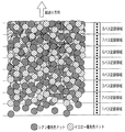
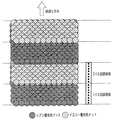
図51(a)および(b)はこの場合の紙面断面を示す。ここでは1パス目(往路走査)で白紙上に千鳥記録が行われ、2パス目(復路走査)で逆千鳥記録が行われる場合を示している。図51(a)は1パス目(往路)記録直後のインクの様子を示し、ここで黒く塗りつぶした部分はシアンインク、斜線で示す部分はイエローインクである。イエローインクはシアンインクと同位置に僅かな時間差をもって打ち込まれているので、紙に吸収されると、シアンインクはにじみが少なく濃度の濃い状態で、一方イエローインクはシアンインクの下側や周辺部に回り込むように大きくにじみ、濃度の薄い状態となる。また、このとき、これらのインクは隣接画素までその吸収が及び、紙面上が殆どインクで埋め尽くされた形となる(図51(a))。
【0029】
この条件の下で行われる2パス目(復路)の記録は、既に隣接のインクが吸収されている上に着弾される。2パス目は復路走査であるからイエローインクが先に、シアンインクは後に記録される(図51(b))。このままインクが吸収されると、最終的には図51(c)のように両色ともあまり表面に現れない吸収状態になる。そして、最終的な完成画像としては1番最初に記録されたシアンの濃度が最も強く強調され、この記録領域は、シアンが強調されたグリーン画像となる。逆に、復路走査を1パス目とした上記記録領域と隣合う記録領域においては、シアンとイエローとが逆転し、イエローを優先とした色味のグリーン画像が得られる。
【0030】
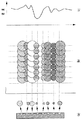
以上2つの記録領域が現れる様子を示したものが図52であり、図49で説明した方法で往復記録を16ノズルのマルチノズルヘッドを用いて実施した場合である。この図に見るように、常にヘッドの先行半分が8ドット幅からなる各領域の優先色を決定し、往復走査でその優先色が逆転していることがわかる。ここでは、千鳥状マスクを適用したものとして説明したが、先に述べた特開平7−52390号公報に開示されているランダムマスク記録法でも同様の結果であり、優先色の異なる2つの領域が交互に存在するため、分割記録においても未だ色むらが現れて画像を劣化させ、往復記録が困難な状態となっていた。
【0031】
上記色むらによる弊害の解決を図ったものとして、特開平6−22106号公報に開示された発明が挙げられる。これによれば、m×n画素のグループ(以下集中画素または集中ドットという)を記録単位とし、これらが互いに隣接しない配列マスクを用いて記録する。m×nで固めて記録する分、白紙領域へのはみ出し量が少なくなり、往路と復路との優先色の差も無くなり、色むらの弊害も軽減される効果が開示されている。
【0032】
以上のように、従来は、基本的にランダムマスクを適用しながらその周期性を目立たせないようにする手法(特開平7−125311号公報)や、m×n画素のグループを記録単位とし、これらが互いに隣接しない配列マスクを用いて記録する手法により、マルチパス記録の効果を画像上に反映させてきた。
【0033】
【発明が解決しようとする課題】
しかしながら、上記特開平7−125311号、特開平6−22106号および特開平7−52391号等の各号公報に開示された技術も、近年求められるようになってきている高品位な写真調画像の記録には十分ではなかった。
【0034】
特開平7−125311号公報に開示された技術を適用しても、近年要求される数pl(ピコリットル)という微少量のインクを単位として構成される写真画質においてはやはりテクスチャーの存在が銀塩写真との差を感じさせてしまうのである。また、特開平6−22106号および特開平7−52391号の各号公報に開示された技術については、色むら抑制ヘの効果を十分にするための集中ドット単位の固まりが人間の視覚解像度を超えて、テクスチャーが確認されてしまうのである。すなわち、デスクトップパブリッシングや、グラフィック,テキスト画像に対しては十分対応しきれていたものの、近年需要が増している写真画質においては弊害となりうる。よって、現状では分割記録数を多くしたランダムマスクを用いることでの対応が一般的であるが、スループットを上げるために双方向プリントを行うと、やはり若干の色むらが残り、往方向プリント時と復方向プリント時とのインク着弾位置のずれがテクスチャーとなって現われ、画像品位を低下させる原因となっていた。
【0035】
さらに、双方向プリントでは、往方向走査によるドット形成位置(インク着弾位置)と復方向走査によるドット形成位置とのずれが新たな誤差要因として加わり、これによる画像品位の低下も写真画質の実現を阻むものとなる。プリント装置をユーザが入手した際あるいはその後の使用時において特開平10−329381号公報に記載されたような技術を適用することで、双方向プリントにおける往復走査のドット形成位置合わせ(双方向レジストレーション)の処理を行うことができる。
【0036】
しかしながら、双方向レジストレーション処理を行っても、実際の記録動作で付与されたインクの量によってはプリント媒体表面が部分的に浮き上がる現象(以下、これをコックリングという)が生じることがあり、双方向レジストレーションのための調整適正値が局所的に他の部位と異なってしまうことがある。このような場合は、浮き上がっている部分のみ画像がざらついて感じられることがあり、部分的なざらつきであるが故に余計に確認されやすい。また、コックリングの状態はプリント媒体の種類や使用環境、さらに記録データ量にも影響を受け、その発生部位もプリント媒体上で不定である。そして、プリント媒体表面のうねりの多い部分に上記テクスチャーが変則的に現れ、画像品位を低下させる。すなわち、双方向レジストレーション処理を行ってもそのようなコックリングの発生に対応しきれないのである。
【0037】
本発明は、以上のような問題点に鑑みてなされたものであり、同一画像領域に対しては相補的な関係にある画素配列に従った複数回の主走査を適用しつつ分割プリントを行う場合にあって、高画質の画像を形成できるようにすること、すなわち、ざらつきや色むらのない写真画質の画像を記録できるようにすることに寄与するマスクパターンの製造方法を提供することを目的とする。
【0038】
【課題を解決するための手段】
そのために、本発明の第1の形態は、インクを吐出するための複数の吐出口を配列してなるプリントヘッドを前記複数の吐出口の配列方向とは異なる主走査方向に走査させ、複数回の前記主走査にてプリント媒体上に画像の形成を行うために所定領域に形成される画像のデータから複数回の前記主走査それぞれに対応する各走査用画像データを生成するためのマスクパターンの製造方法において、
マスクパターンの少なくとも一部を構成する所定の範囲のマスクエリア内にプリント許容画素をランダムに設定する第1工程と、
前記第1工程で設定されたプリント許容画素との相対位置に応じた斥力ポテンシャルを前記マスクエリア内の画素に対して設定する第2工程と、
前記斥力ポテンシャルの和が最小となる前記マスクエリア内の位置の画素を新たなプリント許容画素として設定する第3工程と、
前記マスクエリア内に新たに設定されたプリント許容画素に前記斥力ポテンシャルを付与する第4工程と、
を有し、
前記第3工程と前記第4工程とを複数回繰り返して行うことを特徴とする。
【0039】
また、本発明の第2の形態は、インクを吐出するための複数の吐出口を配列してなるプリントヘッドを前記複数の吐出口の配列方向とは異なる主走査方向に走査させ、複数回の前記主走査にてプリント媒体上に画像の形成を行うために所定領域に形成される画像のデータから複数回の前記主走査それぞれに対応する各走査用画像データを生成するためのマスクパターンの製造方法において、マスクパターンのマスクエリア内の前記複数回行われる前記主走査のうち1回の主走査に対応する範囲内に、プリント許容画素が設定され、前記複数回の主走査のうち他の回の主走査に対応する範囲内の、前記1回の主走査に対応する範囲内に設定されたプリント許容画素に位置的に対応する画素がプリント非許容画素として設定され、プリント許容画素との相対位置に応じた斥力ポテンシャルが前記マスクエリア内の画素に設定されている状態を得る工程Aと、前記非プリント許容画素として設定された画素を除き、前記斥力ポテンシャルの和が最小となる前記マスクエリア内の位置の画素を新たなプリント許容画素として設定する工程Bと、を有することを特徴とする。
【0045】
第1または第2の形態において、前記複数回の主走査のうち少なくとも第1番目の主走査に適用される前記マスク配列が、前記主走査方向にm画素および前記副走査方向にn画素(m,nは整数。ただし少なくとも一方は2以上)のサイズを持つ集中画素を単位として規定されるものとすることができる。
【0048】
第1または第2の形態において、前記画像形成工程または手段では、前記同一画像領域に対し往方向および復方向についてそれぞれ少なくとも2回の前記主走査が行われ、前記少なくとも2回の往方向の主走査に適用される前記マスク配列の和、および/または前記少なくとも2回の復方向の主走査に適用される前記マスク配列の和についても、前記プリント許容画素と前記非プリント許容画素との配置が視覚的に好ましくなるような、低周波成分が少なくかつ分散性の高い配列であるものとすることができる。
【0049】
第1または第2の形態において、前記画像形成工程または手段では、前記同一画像領域に対し往方向および復方向についてそれぞれ少なくとも2回の前記主走査が行われ、前記少なくとも2回の往方向の主走査に適用される前記マスク配列の和、および/または前記少なくとも2回の復方向の主走査に適用される前記マスク配列の和が、前記主走査方向にm画素および前記副走査方向にn画素(m,nは整数。ただし少なくとも一方は2以上)のサイズを持つ集中画素を単位とした画素配列であるものとすることができる。
【0050】
第1または第2の形態において、前記少なくとも2回の往方向の主走査に適用される前記マスク配列の和、および/または前記少なくとも2回の復方向の主走査に適用される前記マスク配列の和についても、前記プリント許容画素と前記非プリント許容画素との配置が視覚的に好ましくなるような、低周波成分が少なくかつ分散性の高い配列であるものとすることができる。
【0051】
第1または第2の形態において、前記マスク配列は、前記プリント対象として入力される画像を2値化処理した際のマスク配列と同期しないものとすることができる。
【0052】
第1または第2の形態において、前記プリントヘッドには前記複数の吐出口が前記搬送のピッチの整数倍の間隔をもって前記副走査方向に配列され、前記画像形成工程または手段は前記複数回の主走査と前記搬送とを行うことで前記画像形成を行うものであり、前記適用工程または手段は、1回の前記主走査でプリントされる前記画素配列に、視覚的に好ましくなるような低周波成分が少なくかつ分散性の高いマスク配列を適用することことができる。
【0053】
第1または第2の形態において、前記画像形成に際し、前記同一画像領域に対する全体のデータプリント量に対する前記複数回の主走査のうちの奇数番目の主走査におけるデータプリント量の比率の和を、前記複数回の主走査のうちの偶数番目の主走査におけるデータプリント量の比率の和より小となるよう制御する工程または手段をさらに具えることができる。
【0058】
第1または第2の形態において、前記画像形成に際し、前記複数回の主走査のうちの第1番目の主走査におけるデータプリント量の前記比率を第2番目の主走査におけるデータプリント量の前記比率より小とするとともに、前記第1番目の主走査および前記第2番目の主走査での形成ドットによる前記プリント媒体の被覆率の和を50%より大となるよう制御する工程または手段をさらに具えることができる。
【0060】
第1または第2の形態において、前記画像形成に際し、前記同一画像領域に対する全体のデータプリント量に対する前記複数回の主走査のうちの奇数番目の主走査におけるデータプリント量の比率の和を、前記複数回の主走査のうちの偶数番目の主走査におけるデータプリント量の比率の和より小となるよう制御する第1制御工程またはモードと、
該第1制御工程またはモードより少ない複数回の主走査として前記第1制御工程またはモードと同様の制御を行うとともに、当該複数回の主走査のうち少なくとも第1番目の主走査での画素の配列を、前記主走査方向にm画素および前記副走査方向にn画素(m,nは整数。ただし少なくとも一方は2以上)の画素群を単位として規定する第2制御工程またはモードと、
をさらに具えることができる。
【0066】
本発明によれば、複数のインク吐出口を配列したプリントヘッドを用いて、前記複数のインク吐出口の配列方向と垂直な方向に双方向プリント走査を行うとともに、前記複数のインク吐出口の配列と平行な方向に順次紙送りを行うことにより、プリント媒体上に画像を完成させていくシリアル型のインクジェットプリント装置にあって、プリント許容画素と非プリント許容画素からなる画素配列が互いに補完の関係にある複数の前記画素配列を用いながら複数回のプリント走査で紙面上に画像を完成される分割プリント法を採用するとともに、1回のプリント走査でプリント媒体上にプリントされた前記画素配列が視覚的に好ましくなるような配列(例えば擬似周期的配列)となるようにすることにより、プリント中のプリント媒体表面に縦方向あるいは横方向のインク着弾位置ずれが起こったとしても、ざらつきの少ない安定した画像を得ることができる。
【0067】
また、本発明によれば、全体のデータプリント量に対する前記複数回の往復走査のうちの奇数番目の走査におけるデータプリント量の比率の和を、前記複数回の往復走査のうちの偶数番目の走査におけるデータプリント量の比率の和より小となるようにすることにより、ないしは、前記複数回の往復走査のうちの第1番目の走査におけるデータプリント量の前記比率を第2番目の走査におけるデータプリント量の前記比率より小となるようにすることにより、色むらのない写真画質を双方向プリントで高速に記録することが可能となる。さらに、プリント画素と非プリント画素との配列が視覚的に好ましくなるような擬似周期的配列マスクを導入することにより、より滑らかで画像弊害の少ないプリントが可能となる。
【0068】
【発明の実施の形態】
以下、図面を参照して本発明の記録装置に係る実施形態を説明する。
【0069】
なお、以下に説明する実施形態では、インクジェット記録方式を用いた記録装置としてプリンタを例に挙げ説明する。
【0070】
そして、本明細書において、「プリント」(「記録」という場合もある)とは、文字、図形等有意の情報を形成する場合のみならず、有意無意を問わず、また人間が視覚で知覚し得るように顕在化したものであるか否かを問わず、広くプリント媒体上に画像、模様、パターン等を形成する、または媒体の加工を行う場合も言うものとする。
【0071】
ここで、「プリント媒体」または「記録シート」とは、一般的なプリント装置で用いられる紙のみならず、広く、布、プラスチック・フィルム、金属板等、ガラス、セラミックス、木材、皮革等、インクを受容可能な物も言うものとするが、以下では「記録媒体」または単に「紙」という場合もある。
【0072】
さらに、「インク」(「液体」という場合もある)とは、上記「プリント」の定義と同様広く解釈されるべきもので、プリント媒体上に付与されることによって、画像、模様、パターン等の形成またはプリント媒体の加工、或いはインクの処理(例えばプリント媒体に付与されるインク中の色材の凝固または不溶化)に供され得る液体を言うものとする。
【0073】
1.装置本体
図1及び図2にインクジェット記録方式を用いたプリンタの概略構成を示す。図1において、この実施形態におけるプリンタの装置本体M1000の外殻は、下ケースM1001、上ケースM1002、アクセスカバーM1003及び排出トレイM1004を含む外装部材と、その外装部材内に収納されたシャーシM3019(図2参照)とから構成される。
【0074】
シャーシM3019は、所定の剛性を有する複数の板状金属部材によって構成され、記録装置の骨格をなし、後述の各記録動作機構を保持するものとなっている。
【0075】
また、前記下ケースM1001は装置本体M1000の外装の略下半部を、上ケースM1002は装置本体M1000の外装の略上半部をそれぞれ形成しており、両ケースの組合せによって内部に後述の各機構を収納する収納空間を有する中空体構造をなしている。装置本体M1000の上面部及び前面部には、それぞれ、開口部が形成されている。
【0076】
さらに、排出トレイM1004は、その一端部が下ケースM1001に回転自在に保持され、その回転によって下ケースM1001の前面部に形成される前記開口部を開閉させ得るようになっている。このため、記録動作を実行させる際には、排出トレイM1004を前面側へと回転させて開口部を開成させることにより、ここから記録シートが排出可能となると共に排出された記録シートPを順次積載し得るようになっている。また、排紙トレイM1004には、2枚の補助トレイM1004a,M1004bが収納されており、必要に応じて各トレイを手前に引き出すことにより、用紙の支持面積を3段階に拡大、縮小させ得るようになっている。
【0077】
アクセスカバーM1003は、その一端部が上ケースM1002に回転自在に保持され、上面に形成される開口部を開閉し得るようになっており、このアクセスカバーM1003を開くことによって本体内部に収納されている記録ヘッドカートリッジH1000あるいはインクタンクH1900等の交換が可能となる。なお、ここでは特に図示しないが、アクセスカバーM1003を開閉させると、その裏面に形成された突起がカバー開閉レバーを回転させるようになっており、そのレバーの回転位置をマイクロスイッチなどで検出することにより、アクセスカバーの開閉状態を検出し得るようになっている。
【0078】
また、上ケースM1002の後部上面には、電源キーE0018及びレジュームキーE0019が押下可能に設けられると共に、LED E0020が設けられており、電源キーE0018を押下すると、LED E0020が点灯し記録可能であることをオペレータに知らせるものとなっている。また、LED E0020は点滅の仕方や色の変化をさせたり、プリンタのトラブル等をオペレータに知らせる等種々の表示機能を有する。さらに、ブザーE0021(図7)をならすこともできる。なお、トラブル等が解決した場合には、レジュームキーE0019を押下することによって記録が再開されるようになっている。
【0079】
2.記録動作機構
次に、プリンタの装置本体M1000に収納、保持される本実施形態における記録動作機構について説明する。
【0080】
本実施形態における記録動作機構としては、記録シートPを装置本体内へと自動的に給送する自動給送部M3022と、自動給送部から1枚ずつ送出される記録シートPを所定の記録位置へと導くと共に、記録位置から排出部M3030へと記録シートPを導く搬送部M3029と、記録位置に搬送された記録シートPに所望の記録を行なう記録部と、前記記録部等に対する回復処理を行う回復部(M5000)とから構成されている。
【0081】
ここで、記録部について説明するに、その記録部は、キャリッジ軸M4021によって移動可能に支持されたキャリッジM4001と、このキャリッジM4001に着脱可能に搭載される記録ヘッドカートリッジH1000とからなる。
【0082】
2.1 記録ヘッドカートリッジ
まず、記録部に用いられる記録ヘッドカートリッジについて図3〜5に基づき説明する。
【0083】
この実施形態における記録ヘッドカートリッジH1000は、図3に示すようにインクを貯留するインクタンクH1900と、このインクタンクH1900から供給されるインクを記録情報に応じてノズルから吐出させる記録ヘッドH1001とを有する。記録ヘッドH1001は、後述するキャリッジM4001に対して着脱可能に搭載される、いわゆるカートリッジ方式を採るものとなっている。
【0084】
ここに示す記録ヘッドカートリッジH1000では、写真調の高画質なカラー記録を可能とするため、インクタンクとして、例えば、ブラック、ライトシアン、ライトマゼンタ、シアン、マゼンタ及びイエローの各色独立のインクタンクH1900が用意されており、図4に示すように、それぞれが記録ヘッドH1001に対して着脱自在となっている。
【0085】
そして,記録ヘッドH1001は、図5の分解斜視図に示すように、記録素子基板H1100、第1のプレートH1200、電気配線基板H1300、第2のプレートH1400、タンクホルダーH1500、流路形成部材H1600、フィルターH1700、シールゴムH1800から構成されている。
【0086】
記録素子基板H1100には、Si基板の片面にインクを吐出するための複数の記録素子と、各記録素子に電力を供給するAl等の電気配線とが成膜技術により形成され、この記録素子に対応した複数のインク流路と複数の吐出口H1100Tとがフォトリソグラフィ技術により形成されると共に、複数のインク流路にインクを供給するためのインク供給口が裏面に開口するように形成されている。また、記録素子基板H1100は第1のプレートH1200に接着固定されており、ここには、前記記録素子基板H1100にインクを供給するためのインク供給口H1201が形成されている。さらに、第1のプレートH1200には、開口部を有する第2のプレートH1400が接着固定されており、この第2のプレートH1400を介して、電気配線基板H1300が記録素子基板H1100に対して電気的に接続されるよう保持されている。この電気配線基板H1300は、記録素子基板H1100にインクを吐出するための電気信号を印加するものであり、記録素子基板H1100に対応する電気配線と、この電気配線端部に位置し本体からの電気信号を受け取るための外部信号入力端子H1301とを有しており、外部信号入力端子H1301は、後述のタンクホルダーH1500の背面側に位置決め固定されている。
【0087】
一方、インクタンクH1900を着脱可能に保持するタンクホルダーH1500には、流路形成部材H1600が例えば、超音波溶着により固定され、インクタンクH1900から第1のプレートH1200に亘るインク流路H1501を形成している。また、インクタンクH1900と係合するインク流路H1501のインクタンク側端部には、フィルターH1700が設けられており、外部からの塵埃の侵入を防止し得るようになっている。また、インクタンクH1900との係合部にはシールゴムH1800が装着され、係合部からのインクの蒸発を防止し得るようになっている。
【0088】
さらに、前述のようにタンクホルダーH1500、流路形成部材H1600、フィルターH1700及びシールゴムH1800から構成されるタンクホルダー部と、前記記録素子基板H1100、第1のプレートH1200、電気配線基板H1300及び第2のプレートH1400から構成される記録素子部とを、接着等で結合することにより、記録ヘッドH1001を構成している。
【0089】
2.2 キャリッジ
次に、図2を参照して記録ヘッドカートリッジH1000を搭載するキャリッジM4001を説明する。
【0090】
図2に示すように、キャリッジM4001には、キャリッジM4001と係合し記録ヘッドH1001をキャリッジM4001上の所定の装着位置に案内するためのキャリッジカバーM4002と、記録ヘッドH1001のタンクホルダーH1500と係合し記録ヘッドH1001を所定の装着位置にセットさせるよう押圧するヘッドセットレバーM4007とが設けられている。
【0091】
すなわち、ヘッドセットレバーM4007はキャリッジM4001の上部にヘッドセットレバー軸に対して回動可能に設けられると共に、記録ヘッドH1001との係合部には、ばね付勢されるヘッドセットプレート(不図示)が備えられ、このばね力によって記録ヘッドH1001を押圧しながらキャリッジM4001に装着する構成となっている。
【0092】
また、キャリッジM4001の記録ヘッドH1001との別の係合部にはコンタクトフレキシブルプリントケーブル(図7参照、以下、コンタクトFPCと称す)E0011が設けられ、コンタクトFPC E0011上のコンタクト部と記録ヘッドH1001に設けられたコンタクト部(外部信号入力端子)H1301とが電気的に接触し、記録のための各種情報の授受や記録ヘッドH1001への電力の供給などを行い得るようになっている。
【0093】
ここでコンタクトFPC E0011のコンタクト部とキャリッジM4001との間には不図示のゴムなどの弾性部材が設けられ、この弾性部材の弾性力とヘッドセットレバーばねによる押圧力とによってコンタクト部とキャリッジM4001との確実な接触を可能とするようになっている。さらに前記コンタクトFPC E0011はキャリッジM4001の背面に搭載されたキャリッジ基板E0013に接続されている(図7参照)。
【0094】
3.スキャナ
この実施形態におけるプリンタは、上述した記録ヘッドカートリッジH1000の代わりにキャリッジM4001にスキャナを装着することで読取装置としても使用することができる。
【0095】
このスキャナは、プリンタ側のキャリッジM4001と共に主走査方向に移動し、記録媒体に代えて給送された原稿画像をその主走査方向への移動の過程で読み取るようになっており、その主走査方向の読み取り動作と原稿の副走査方向の給送動作とを交互に行うことにより、1枚の原稿画像情報を読み取ることができる。
【0096】
図6(a)および(b)は、このスキャナM6000の概略構成を説明するために、スキャナM6000を上下逆にして示す図である。
【0097】
図示のように、スキャナホルダM6001は、略箱型の形状であり、その内部には読み取りに必要な光学系・処理回路などが収納されている。また、このスキャナM6000をキャリッジM4001へと装着した時に、原稿面と対面する部分には読取部レンズM6006が設けられており、このレンズM6006により原稿面からの反射光を内部の読取部に収束することで原稿画像を読み取るようになっている。一方、照明部レンズM6005は内部に不図示の光源を有し、その光源から発せられた光がレンズM6005を介して原稿へと照射される。
【0098】
スキャナホルダM6001の底部に固定されたスキャナカバーM6003は、スキャナホルダM6001内部を遮光するように嵌合し、側面に設けられたルーバー状の把持部によってキャリッジM4001への着脱操作性の向上を図っている。スキャナホルダM6001の外形形状は記録ヘッドH1001と略同形状であり、キャリッジM4001へは記録ヘッドカートリッジH1000と同様の操作で着脱することができる。
【0099】
また、スキャナホルダM6001には、読取り処理回路を有する基板が収納される一方、この基板に接続されたスキャナコンタクトPCBが外部に露出するよう設けられており、キャリッジM4001へとスキャナM6000を装着した際、スキャナコンタクトPCB M6004がキャリッジM4001側のコンタクトFPC E0011に接触し、基板を、キャリッジM4001を介して本体側の制御系に電気的に接続させるようになっている。
【0100】
4.プリンタの電気回路の構成
次に、本発明の実施形態における電気的回路構成を説明する。
図7は、この実施形態における電気的回路の全体構成例を概略的に示す図である。
【0101】
この実施形態における電気的回路は、主にキャリッジ基板(CRPCB)E0013、メインPCB(Printed Circuit Board)E0014、電源ユニットE0015等によって構成されている。
ここで、電源ユニットE0015は、メインPCB E0014と接続され、各種駆動電源を供給するものとなっている。
また、キャリッジ基板E0013は、キャリッジM4001(図2)に搭載されたプリント基板ユニットであり、コンタクトFPC E0011を通じて記録ヘッドとの信号の授受を行うインターフェースとして機能する他、キャリッジM4001の移動に伴ってエンコーダセンサE0004から出力されるパルス信号に基づき、エンコーダスケールE0005とエンコーダセンサE0004との位置関係の変化を検出し、その出力信号をフレキシブルフラットケーブル(CRFFC)E0012を通じてメインPCB E0014へと出力する。
【0102】
さらに、メインPCB E0014はこの実施形態におけるインクジェット記録装置の各部の駆動制御を司るプリント基板ユニットであり、紙端検出センサ(PEセンサ)E0007、ASF(自動給紙装置)センサE0009、カバーセンサE0022、パラレルインターフェース(パラレルI/F)E0016、シリアルインターフェース(シリアルI/F)E0017、レジュームキーE0019、LED E0020、電源キーE0018、ブザーE0021等に対するI/Oポートを基板上に有する。またさらに、キャリッジM1400を主走査させるための駆動源をなすモータ(CRモータ)E0001、記録媒体を搬送するための駆動源をなすモータ(LFモータ)E0002、記録ヘッドの回動動作と記録媒体の給紙動作に兼用されるモータ(PGモータ)E0003と接続されてこれらの駆動を制御する他、インクエンプティセンサE0006、GAPセンサE0008、PGセンサE0010、CRFFC E0012、電源ユニットE0015との接続インターフェイスを有する。
【0103】
図8は、メインPCB E0014の内部構成を示すブロック図である。図において、E1001はCPUであり、このCPU E1001は内部に発振回路E1005に接続されたクロックジェネレータ(CG) E1002を有し、その出力信号E1019によりシステムクロックを発生する。また、制御バスE1014を通じてROM E1004およびASIC(Application Specific Integrated Circuit) E1006に接続され、ROMに格納されたプログラムに従って、ASIC E1006の制御、電源キーからの入力信号E1017、及びレジュームキーからの入力信号E1016、カバー検出信号E1042、ヘッド検出信号(HSENS)E1013の状態の検知を行ない、さらにブザー信号(BUZ)E1018によりブザーE0021を駆動し、内蔵されるA/DコンバータE1003に接続されるインクエンプティ検出信号(INKS)E1011及びサーミスタによる温度検出信号(TH)E1012の状態の検知を行う一方、その他各種論理演算・条件判断等を行ない、インクジェット記録装置の駆動制御を司る。
【0104】
ここで、ヘッド検出信号E1013は、記録ヘッドカートリッジH1000からフレキシブルフラットケーブルE0012、キャリッジ基板E0013及びコンタクトフレキシブルプリントケーブルE0011を介して入力されるヘッド搭載検出信号であり、インクエンプティ検出信号E1011はインクエンプティセンサE0006から出力されるアナログ信号、温度検出信号E1012はキャリッジ基板E0013上に設けられたサーミスタ(図示せず)からのアナログ信号である。
【0105】
E1008はCRモータドライバであって、モータ電源(VM)E1040を駆動源とし、ASIC E1006からのCRモータ制御信号E1036に従って、CRモータ駆動信号E1037を生成し、CRモータE0001を駆動する。E1009はLF/PGモータドライバであって、モータ電源E1040を駆動源とし、ASIC E1006からのパルスモータ制御信号(PM制御信号)E1033に従ってLFモータ駆動信号E1035を生成し、これによってLFモータを駆動すると共に、PGモータ駆動信号E1034を生成してPGモータを駆動する。
【0106】
E1010は電源制御回路であり、ASIC E1006からの電源制御信号E1024に従って発光素子を有する各センサ等への電源供給を制御する。パラレルI/F E0016は、ASIC E1006からのパラレルI/F信号E1030を、外部に接続されるパラレルI/FケーブルE1031に伝達し、またパラレルI/FケーブルE1031の信号をASIC E1006に伝達する。シリアルI/F E0017は、ASIC E1006からのシリアルI/F信号E1028を、外部に接続されるシリアルI/FケーブルE1029に伝達し、また同ケーブルE1029からの信号をASIC E1006に伝達する。
【0107】
一方、電源ユニットE0015からは、ヘッド電源(VH)E1039及びモータ電源(VM)E1040、ロジック電源(VDD)E1041が供給される。また、ASIC E1006からのヘッド電源ON信号(VHON)E1022及びモータ電源ON信号(VMOM)E1023が電源ユニットE0015に入力され、それぞれヘッド電源E1039及びモータ電源E1040のON/OFFを制御する。電源ユニットE0015から供給されたロジック電源(VDD)E1041は、必要に応じて電圧変換された上で、メインPCB E0014内外の各部へ供給される。
【0108】
またヘッド電源信号E1039は、メインPCB E0014上で平滑化された後にフレキシブルフラットケーブルE0011へと送出され、記録ヘッドカートリッジH1000の駆動に用いられる。
E1007はリセット回路で、ロジック電源電圧E1041の低下を検出して、CPU E1001及びASIC E1006にリセット信号(RESET)E1015を供給し、初期化を行なう。
【0109】
このASIC E1006は1チップの半導体集積回路であり、制御バスE1014を通じてCPU E1001によって制御され、前述したCRモータ制御信号E1036、PM制御信号E1033、電源制御信号E1024、ヘッド電源ON信号E1022、及びモータ電源ON信号E1023等を出力し、パラレルI/F E0016およびシリアルI/F E0017との信号の授受を行なう他、PEセンサE0007からのPE検出信号(PES)E1025、ASFセンサE0009からのASF検出信号(ASFS)E1026、記録ヘッドと記録媒体とのギャップを検出するためのセンサ(GAP)センサE0008からのGAP検出信号(GAPS)E1027、PGセンサE0010からのPG検出信号(PGS)E1032の状態を検知して、その状態を表すデータを制御バスE1014を通じてCPU E1001に伝達し、入力されたデータに基づきCPU E1001はLED駆動信号E1038の駆動を制御してLEDE0020の点滅を行なう。
【0110】
さらに、エンコーダ信号(ENC)E1020の状態を検知してタイミング信号を生成し、ヘッド制御信号E1021で記録ヘッドカートリッジH1000とのインターフェイスをとり記録動作を制御する。ここにおいて、エンコーダ信号(ENC)E1020はフレキシブルフラットケーブルE0012を通じて入力されるCRエンコーダセンサE0004の出力信号である。また、ヘッド制御信号E1021は、フレキシブルフラットケーブルE0012、キャリッジ基板E0013、及びコンタクトFPC E0011を経て記録ヘッドH1000に供給される。
【0111】
図9は、ASIC E1006の内部構成例を示すブロック図である。
なお、同図において、各ブロック間の接続については、記録データやモータ制御データ等、ヘッドや各部機構部品の制御にかかわるデータの流れのみを示しており、各ブロックに内蔵されるレジスタの読み書きに係わる制御信号やクロック、DMA制御にかかわる制御信号などは図面上の記載の煩雑化を避けるため省略している。
【0112】
図中、E2002はPLLコントローラであり、図9に示すようにCPU E1001から出力されるクロック信号(CLK)E2031及びPLL制御信号(PLLON)E2033により、ASIC E1006内の大部分へと供給するクロック(図示しない)を発生する。
【0113】
また、E2001はCPUインターフェース(CPUI/F)であり、リセット信号E1015、CPU E1001から出力されるソフトリセット信号(PDWN)E2032、クロック信号(CLK)E2031及び制御バスE1014からの制御信号により、以下に説明するような各ブロックに対するレジスタ読み書き等の制御や、一部ブロックへのクロックの供給、割り込み信号の受け付け等(いずれも図示しない)を行ない、CPU E1001に対して割り込み信号(INT)E2034を出力し、ASIC E1006内部での割り込みの発生を知らせる。
【0114】
また、E2005はDRAMであり、記録用のデータバッファとして、受信バッファE2010、ワークバッファE2011、プリントバッファE2014、展開用データバッファE2016などの各領域を有すると共に、モータ制御用としてモータ制御バッファE2023を有し、さらにスキャナ動作モード時に使用するバッファとして、上記の各記録用データバッファに代えて使用されるスキャナ取込みバッファE2024、スキャナデータバッファE2026、送出バッファE2028などの領域を有する。
【0115】
また、このDRAM E2005は、CPU E1001の動作に必要なワーク領域としても使用されている。すなわち、E2004はDRAM制御部であり、制御バスによるCPU E1001からDRAM E2005へのアクセスと、後述するDMA制御部E2003からDRAM E2005へのアクセスとを切り替えて、DRAM E2005への読み書き動作を行なう。
【0116】
DMA制御部E2003では、各ブロックからのリクエスト(図示せず)を受け付けて、アドレス信号や制御信号(図示せず)、書込み動作の場合には書込みデータE2038、E2041、E2044、E2053、E2055、E2057などをDRAM制御部E2004に出力してDRAMアクセスを行なう。また読み出しの場合には、DRAM制御部E2004からの読み出しデータE2040、E2043、E2045、E2051、E2054、E2056、E2058、E2059を、リクエスト元のブロックに受け渡す。
【0117】
また、E2006は、IEEE1284I/Fであり、CPUI/F E2001を介したCPU E1001の制御により、パラレルI/F E0016を通じて、図示しない外部ホスト機器との双方向通信インターフェイスを行なう他、記録時にはパラレルI/F E0016からの受信データ(PIF受信データE2036)をDMA処理によって受信制御部E2008へと受け渡し、スキャナ読み取り時にはDRAM E2005内の送出バッファE2028に格納されたデータ(IEEE1284送信データ(RDPIF)E2059)をDMA処理によりパラレルI/Fに送信する。
【0118】
E2007は、ユニバーサルシリアルバス(USB)I/Fであり、CPUI/F E2001を介したCPU E1001の制御により、シリアルI/F E0017を通じて、図示しない外部ホスト機器との双方向通信インターフェイスを行なう他、印刷時にはシリアルI/F E0017からの受信データ(USB受信データE2037)をDMA処理により受信制御部E2008に受け渡し、スキャナ読み取り時にはDRAM E2005内の送出バッファE2028に格納されたデータ(USB送信データ(RDUSB)E2058)をDMA処理によりシリアルI/F E0017に送信する。受信制御部E2008は、1284I/F E2006もしくはUSBI/F E2007のうちの選択されたI/Fからの受信データ(WDIF)E2038)を、受信バッファ制御部E2039の管理する受信バッファ書込みアドレスに、書込む。
【0119】
E2009は圧縮・伸長DMAコントローラであり、CPUI/F E2001を介したCPUE1001の制御により、受信バッファE2010上に格納された受信データ(ラスタデータ)を、受信バッファ制御部E2039の管理する受信バッファ読み出しアドレスから読み出し、そのデータ(RDWK)E2040を指定されたモードに従って圧縮・伸長し、記録コード列(WDWK)E2041としてワークバッファ領域に書込む。
【0120】
E2013は記録バッファ転送DMAコントローラで、CPUI/F E2001を介したCPU E1007の制御によってワークバッファE2011上の記録コード(RDWP)E2043を読み出し、各記録コードを、記録ヘッドカートリッジH1000へのデータ転送順序に適するようなプリントバッファE2014上のアドレスに並べ替えて転送(WDWP E2044)する。また、E2012はワーククリアDMAコントローラであり、CPUI/F E2001を介したCPU E1001の制御によって記録バッファ転送DMAコントローラ E2013による転送が完了したワークバッファ上の領域に対し、指定したワークフィルデータ(WDWF)E2042を繰返し書込む。
【0121】
E2015は記録データ展開DMAコントローラであり、CPUI/F E2001を介したCPU E1001の制御により、ヘッド制御部E2018からのデータ展開タイミング信号E2050をトリガとして、プリントバッファ上に並べ替えて書込まれた記録コードと展開用データバッファE2016上に書込まれた展開用データとを読み出し、展開記録データ(RDHDG)E2045をカラムバッファ書込みデータ(WDHDG)E2047としてカラムバッファE2017に書込む。ここで、カラムバッファE2017は、記録ヘッドカートリッジH1000への転送データ(展開記録データ)を一時的に格納するSRAMであり、記録データ展開DMAコントローラE2015とヘッド制御部E2018とのハンドシェーク信号(図示せず)によって両ブロックにより共有管理されている。
【0122】
E2018はヘッド制御部で、CPUI/F E2001を介したCPU E1001の制御により、ヘッド制御信号を介して記録ヘッドカートリッジH1000またはスキャナとのインターフェイスを行なう他、エンコーダ信号処理部E2019からのヘッド駆動タイミング信号E2049に基づき、記録データ展開DMAコントローラに対してデータ展開タイミング信号E2050の出力を行なう。
【0123】
また、印刷時には、前記ヘッド駆動タイミング信号E2049に従って、カラムバッファから展開記録データ(RDHD)E2048を読み出し、そのデータをヘッド制御信号E1021として記録ヘッドカートリッジH1000に出力する。
【0124】
また、スキャナ読み取りモードにおいては、ヘッド制御信号E1021として入力された取込みデータ(WDHD)E2053をDRAM E2005上のスキャナ取込みバッファE2024へとDMA転送する。E2025はスキャナデータ処理DMAコントローラであり、CPUI/F E2001を介したCPUE1001の制御により、スキャナ取込みバッファE2024に蓄えられた取込みバッファ読み出しデータ(RDAV)E2054を読み出し、平均化等の処理を行なった処理済データ(WDAV)E2055をDRAM E2005上のスキャナデータバッファE2026に書込む。
【0125】
E2027はスキャナデータ圧縮DMAコントローラで、CPUI/F E2001を介したCPU E1001の制御により、スキャナデータバッファE2026上の処理済データ(RDYC)E2056を読み出してデータ圧縮を行ない、圧縮データ(WDYC)E2057を送出バッファE2028に書込み転送する。
【0126】
E2019はエンコーダ信号処理部であり、エンコーダ信号(ENC)を受けて、CPU E1001の制御で定められたモードに従ってヘッド駆動タイミング信号E2049を出力する他、エンコーダ信号E1020から得られるキャリッジM4001の位置や速度にかかわる情報をレジスタに格納して、CPU E1001に提供する。CPU E1001はこの情報に基づき、CRモータE0001の制御における各種パラメータを決定する。また、E2020はCRモータ制御部であり、CPUI/F E2001を介したCPU E1001の制御により、CRモータ制御信号E1036を出力する。
【0127】
E2022はセンサ信号処理部で、PGセンサE0010、PEセンサE0007、ASFセンサE0009、及びGAPセンサE0008等から出力される各検出信号E1033,E1025,E1026,E1027を受けて、CPUE1001の制御で定められたモードに従ってこれらのセンサ情報をCPU E1001に伝達する他、LF/PGモータ制御用DMAコントローラ E2021に対してセンサ検出信号E2052を出力する。
【0128】
LF/PGモータ制御用DMAコントローラE2021は、CPUI/F E2001を介したCPU E1001の制御により、DRAM E2005上のモータ制御バッファE2023からパルスモータ駆動テーブル(RDPM)E2051を読み出してパルスモータ制御信号E1033を出力する他、動作モードによっては前記センサ検出信号を制御のトリガとしてパルスモータ制御信号E1033を出力する。
【0129】
また、E2030はLED制御部であり、CPUI/F E2001を介したCPU E1001の制御により、LED駆動信号E1038を出力する。さらに、E2029はポート制御部であり、CPUI/F E2001を介したCPU E1001の制御により、ヘッド電源ON信号E1022、モータ電源ON信号E1023、及び電源制御信号E1024を出力する。
【0130】
5.プリンタの動作
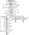
次に、上記のように構成された本発明の実施形態におけるインクジェット記録装置の動作を図10のフローチャートに基づき説明する。
【0131】
AC電源に装置本体1000が接続されると、まず、ステップS1では装置の第1の初期化処理を行なう。この初期化処理では、本装置のROMおよびRAMのチェックなどの電気回路系のチェックを行ない、電気的に本装置が正常に動作可能であるかを確認する。
【0132】
次にステップS2では、装置本体M1000の上ケースM1002に設けられた電源キーE0018がONされたかどうかの判断を行い、電源キーE0018が押された場合には、次のステップS3へと移行し、ここで第2の初期化処理を行う。
【0133】
この第2の初期化処理では、本装置の各種駆動機構及び記録ヘッドのチェックを行なう。すなわち、各種モータの初期化やヘッド情報の読み込みを行うに際し、装置が正常に動作可能であるかを確認する。
【0134】
次にステップS4ではイベント待ちを行なう。すなわち、本装置に対して、外部I/Fからの指令イベント、ユーザ操作によるパネルキーイベントおよび内部的な制御イベントなどを監視し、これらのイベントが発生すると当該イベントに対応した処理を実行する。
【0135】
例えば、ステップS4で外部I/Fからの印刷指令イベントを受信した場合には、ステップS5へと移行し、同ステップでユーザ操作による電源キーイベントが発生した場合にはステップS10へと移行し、同ステップでその他のイベントが発生した場合にはステップS11へと移行する。
【0136】
ここで、ステップS5では、外部I/Fからの印刷指令を解析し、指定された紙種別、用紙サイズ、印刷品位、給紙方法などを判断し、その判断結果を表すデータを本装置内のRAM E2005に記憶し、ステップS6へと進む。
【0137】
次いでステップS6ではステップS5で指定された給紙方法により給紙を開始し、用紙を記録開始位置まで送り、ステップS7に進む。
【0138】
ステップS7では記録動作を行なう。この記録動作では、外部I/Fから送出されてきた記録データを、一旦記録バッファに格納し、次いでCRモータE0001を駆動してキャリッジM4001の主走査方向への移動を開始すると共に、プリントバッファE2014に格納されている記録データを記録ヘッドH1001へと供給して1行の記録を行ない、1行分の記録データの記録動作が終了するとLFモータE0002を駆動し、LFローラM3001を回転させて用紙を副走査方向へと送る。この後、上記動作を繰り返し実行し、外部I/Fからの1ページ分の記録データの記録が終了すると、ステップ8へと進む。
【0139】
ステップS8では、LFモータE0002を駆動し、排紙ローラM2003を駆動し、用紙が完全に本装置から送り出されたと判断されるまで紙送りを繰返し、終了した時点で用紙は排紙トレイM1004a上に完全に排紙された状態となる。
【0140】
次にステップS9では、記録すべき全ページの記録動作が終了したか否かを判定し、記録すべきページが残存する場合には、ステップS5へと復帰し、以下、前述のステップS5〜S9までの動作を繰り返し、記録すべき全てのページの記録動作が終了した時点で記録動作は終了し、その後ステップS4へと移行し、次のイベントを待つ。
【0141】
一方、ステップS10ではプリンタ終了処理を行ない、本装置の動作を停止させる。つまり、各種モータやヘッドなどの電源を切断するために、電源を切断可能な状態に移行した後、電源を切断しステップS4に進み、次のイベントを待つ。
【0142】
また、ステップS11では、上記以外の他のイベント処理を行なう。例えば、本装置の各種パネルキーや外部I/Fからの回復指令や内部的に発生する回復イベントなどに対応した処理を行なう。なお、処理終了後にはステップS4に進み、次のイベントを待つ。
【0143】
6.ヘッドの構成
ここで、本実施形態で用いるヘッドH1001の吐出口群の構成配置について説明する。
【0144】
図11は本実施形態で用いた高密度記録を実現するためのヘッドの模式的正面図である。この例では1列当たり600dpi(ドット/インチ)のピッチ(約42μmピッチ)で128個の吐出口を配列した吐出口列を1色当たり2列、互いに副走査方向(紙送り方向)に約21μmずらして、主走査方向(キャリッジスキャン方向)に設けてあり、1色当たり合計256個の吐出口にて1200dpiの解像度を実現している。さらに、図示の例ではそのような吐出口列を6色に対応して主走査方向に並置し、6色について合計12列の吐出口列で1200dpiの記録を行う一体構造のヘッド構成としている。但し、製造上は並列する2色分が1チップとして同時に作成され、その後3チップを並列して接着させる構成をとっているので、各チップの隣り合う2色のノズル列(ブラック(Bk)およびライトシアン(LC)の組、ライトマゼンタ(LM)およびシアン(C)の組、マゼンタ(M)およびイエロー(Y)の組)は他に比べ駆動条件が似通ったものとなっている。
【0145】
なお、図11に示した1200dpiの解像度のヘッドの場合、紙面上での1画素は約21μm四方の領域となるが、本実施形態で用いる1ドロップは約4plであり、紙面上では直径約45μmの円形ドットを形成する。このとき、1ドットの面積は1570μm2となり、1画素領域の21×21=441μm2よりはるかに大きくなる。
【0146】
7.疑似周期的マスク
以上説明した構成の記録装置およびヘッドを用い、本発明所期の目的を達成するための前提となる疑似周期的マスクを用いた記録方法について説明する。当該記録方法は図10の手順中で記録動作(ステップS7)等を行う際に反映させることができるものである。
【0147】
前述した特開平7−52390号公報に記載されているランダムマスクでは、記録ヘッドの吐出特性に起因する濃度むらや、ノズル毎の記録ドット数の違いによって生じる濃度むらをマスクパターンによって解消するものであるが、メモリ容量の制限によって所定サイズのマスクパターンを繰り返し適用した場合に、マスク全体の周期によって出力画像に繰り返しパターンが生じたり、乱数の低周波成分により粒状性が増加することがあった。特に双方向プリントにおいては、往路と復路の着弾位置ずれの精度が厳しく、僅かなずれが画像のざらつきや周期的なむらを生じることがあった。以下に説明する擬似周期的マスクでは、このようなランダムマスクと比べて、繰り返しパターンの発生や粒状性の増加を抑制し、さらに画像品位を向上させることができる。
【0148】
7.1 疑似周期的マスクを適用するためのインクジェットプリンタの構成
ここで、擬似周期的マスクを適用するための構成例について説明する。
【0149】
図12は本実施形態に係る疑似周期的マスクを適用する構成を説明するためにインクジェットプリンタを簡略かつ模式的に表した図である。図示の構成では、画像データ入力端子300と、画像バッファ301と、アドレスカウンタ302と、マスク生成手段および間引き手段としてのマスク生成部303と、マスクバッファ304と、マスク処理部305と、ROM形態の母マスクの格納手段たるROM形態の母マスクメモリ306と、プリンタ本体307とを具備している。
【0150】
ここで、画像データ入力端子300には、本実施形態のインクジェットプリンタによるプリント対象となる画像データが入力される。画像バッファ301は一回の走査(パス)によりプリントされる画像データを蓄積しておくためのバッファである。アドレスカウンタ302は画像データとマスクデータの同期を取るためのカウンタである。マスク生成部303は画像データに対して間引きを行うために適用するマスクデータを生成する。マスクバッファ304はマスクデータを格納するためのバッファである。マスク処理部305は、画像データとマスクデータとからヘッド駆動信号を生成する。母マスクメモリ306は、予め他の装置により生成された母マスクデータを格納しておくためのメモリである。図12に示されたこれらの各部は機能的に表現されたものであり、具体的には図7ないし図9に示した電気的な回路構成の一部として設けておくことができる。例えば、画像バッファ301はプリントバッファE2014に対応したものとすることができる。
【0151】
プリンタ本体307は、ヘッド駆動信号に従い記録媒体上に画像を形成するものであり、具体的には図1ないし図6に示した機械的構成を含むものである。すなわち、記録ヘッドH1001ないし記録ヘッドカートリッジH1000を記録媒体311に対して主走査させるためのキャリッジM4001等を含む主走査装置309と、記録媒体311を副走査方向に搬送するための各部ローラを含む搬送装置310とを有し、これら装置によって記録ヘッドH1001を記録媒体311に対して相対的に主走査および副走査させることにより、記録媒体311上に画像を形成する。なお、記録ヘッドH1001は複数のプリント素子(ノズル)を有しており、本実施形態では上述のように各色256本のノズルによって画像を形成するが、ここでは擬似周期的マスクについての説明を簡単にするため、1色当たり16本のノズルを副走査方向に1列に配列した記録ヘッドを用い、4パスプリントにて画像を完成させるものとする。
【0152】
図13〜図16はマスク処理部305により画像バッファ301およびマスクバッファ304から記録ヘッド制御信号を生成する手順を説明するための図である。これらの図における(a)の部分は、画像バッファ301の構造および内容を示している。本実施形態の画像バッファ301は、横方向が記録媒体311の主走査方向にプリント可能な画素数と同数の画素に対応しており、縦方向が記録ヘッドH1001の副走査方向のノズル数と同数の画素に対応している。すなわち、図13〜図16の例では、説明の簡略化のために、横方向(主走査方向)の画素数を16画素としているが、例えば、記録媒体311上で記録可能な領域の横幅が8インチ(参考値。約203.2mm)であり、プリンタ本体307の解像度が1200DPI(ドット/インチ)であれば、実際の画像バッファ301の横方向の画素数は9600画素である。また、マスクバッファ304のサイズについても画像バッファ301と同様、横方向を16画素、縦方向をこの説明における記録ヘッドの記録素子と同数の16画素とした。
【0153】
また、図13〜図16においては各マス目が画素に対応しており、画像データに応じた各図(a)の白のマス目は記録がなされない画素を、黒のマス目は記録がなされ得る画素を表すものとする。また、マスクパターンに応じた各図(b)の白のマス目は記録が許容されない画素(すなわちその画素の画像データによらずマスキングされてしまう画素。以下、マスク画素という)を、黒のマス目は記録が許容される画素(すなわちその画素の画像データに応じてドット形成がなされることになる画素。以下、記録許容画素という)を表すものとする。さらに、ヘッド駆動信号に応じた各図(c)の白のマス目は記録がなされない画素を、黒のマス目は実際に記録がなされる画素を表すものとする。
【0154】
図13は第1の走査における記録ヘッド制御信号を生成するためのマスク処理を示した説明図である。まず、第1の走査においては画像バッファ301の下側4画素分の領域に入力画像の上端から4画素分の画像データが格納される(図13(a))。次に、後述する手順によりマスク生成部303から生成された第1のマスクパターン3201(図13(b))と画像バッファ301との画素毎の論理積を取り、ヘッド駆動信号3202(図13(c))を生成する。すなわち、画像バッファ301およびマスクパターン3201において両方とも記録状態である画素に対応する記録素子のみが駆動されることになる。
【0155】
図14は第2の走査における記録ヘッド駆動信号を生成するためのマスク処理を示した説明図である。第1の走査が行われた後、プリンタ本体307の搬送装置310により、この説明における記録ヘッドH1001の記録素子数(16個)の1/4(=4)の紙送りが行われる。従って、画像バッファ301の内容もその分上に移動し、次のデータを画像データ入力端子300より取得し画像バッファ301に格納する(図14(a))。なお、図13〜図16では、説明の都合上、画像データを移動しているように表現しているが、画像バッファ301をリングバッファとして構成しておけば、バッファ内での画像データの移動をアドレスカウンタ302の指示内容の変更のみで処理できるので簡便である。次に、後述する手順によりマスク生成部303から生成された第2のマスクパターン3301(図14(b))と画像バッファ301の画素毎のAND演算を行い、ヘッド駆動信号3302(図14(c))を生成する。
【0156】
図15は第3の走査における記録ヘッド駆動信号を生成するためのマスク処理を示した図である。第2の走査が行われた後、プリンタ本体307の搬送装置310により、この説明における記録ヘッドH1001の記録素子数(16個)の1/4(4個分)の紙送りが行われる。従って、画像バッファ301の内容もその分上に移動し、次のデータを画像データ入力端子300より取得し画像バッファ301に格納する(図15(a))。次に、後述する手順によりマスク生成部303から生成された第2のマスクパターン3401(図15(b))と画像バッファ301の画素毎のAND演算を行い、ヘッド駆動信号3402(図15(c))を生成する。
【0157】
図16は第4の走査における記録ヘッド駆動信号を生成するためのマスク処理を示した説明図である。第3の走査が行われた後、プリンタ本体307の搬送装置310により、この説明における記録ヘッドH1001の記録素子数(16個)の1/4(4個分)の紙送りが行われる。従って、画像バッファ301の内容もその分上に移動し、次のデータを画像データ入力端子300より取得し画像バッファ301に格納する(図16(a))。次に、後述する手順によりマスク生成部303から生成された第2のマスクパターン3501(図16(b))と画像バッファ301の画素毎のAND演算を行い、ヘッド駆動信号3502(図16(c))を生成する。
【0158】
以上の4回の走査(4パス)により、まず全ノズル数の4分の1のヘッド上端部に対応した部分についての画像が完成する。以下同様な処理を繰り返すことにより、画像全体のプリント処理を行う。なお、第5の走査においては、既に画像上端部のプリントは終了しているので、画像バッファ上端部分のデータを捨て、新たに生じた空き領域に次の画素分のデータを格納すればよい。
【0159】
7.2 疑似周期的マスクの生成
本実施形態においては、各パスで記録データを間引くためのマスクパターンとして、特開平7−52390号公報に開示されたようなランダムマスクパターンではなく、低周波成分が少なく分散性が高い疑似周期的マスクパターンを用いる。かかる疑似周期的マスクパターンを、その生成手法とともに説明する。
【0160】
まず、生成手法の第1例として、疑似周期的マスク生成の基準となる母マスクを作成し、その母マスクを展張して疑似周期的マスクを生成する処理について説明する。
【0161】
図17は母マスクの作成手順の一例を示す。なお、ここでは母マスクないしマスクエリアのサイズは縦方向(副走査方向)および横方向(主走査方向)についてそれぞれ16画素分の寸法を持つものとする。
【0162】
まず、母マスクの16×16=256画素の領域において、第1番目のドット配置をランダムに定める(ステップS40)。ここでは、最初のドット位置を(x0,y0)とする。次に、母マスク内のデータを初期化する(ステップS41)。ここでは、ステップS40で定められた最初のドット位置(x0,y0)についてのマスク値を「254」とし、その他のマスク値を「255」とする。次に、ポテンシャルの初期化を行う(ステップS42)。ポテンシャルは、ドット位置からの距離rに対して例えば次の関数f(r)で与えられるものとする。
f(r)=−0.41r+1.21 (r<2)
f(r)=2.76exp(−r) (2≦r<10)
f(r)=0 (r≧10) (1)
【0163】
ドット位置(x0,y0)から任意のマスク位置(x,y)までの距離rは
r={(x−x0)2+(y−y0)2}1/2
で表わされるので、例えば
x0−10<x<x0+10,y0−10<y<y0+10
の領域内で式(1)の関数を適用することで、ドット位置(x0,y0)による任意のマスク位置(x,y)に対するポテンシャルP(x,y)を求めればよい。
【0164】
図18はポテンシャルの形状の一例である。このようなポテンシャルは斥力型のものであり、以降のドット配置処理に斥力型のポテンシャルを適用することにより、既に配置されているドットの近傍に新たなドットが配置されることを防ぐことができる。なお、ポテンシャルの裾がマスクの領域を越える場合は、図19に示すようにマスク領域の反対側に折り返して計算する。これは、マスク境界においてドット配置の不連続性を発生させないためである。
【0165】
次に、母マスク上、ポテンシャルの最も小さい位置を検索し、その位置にドットを追加する(ステップS43)。ポテンシャルの最小値を持つ位置が複数ある場合は、ランダムに1つの位置を選択する。次に、新たに追加配置したドットを含め、既に配置されている全てのドットの位置に対応するマスク値を1つ減らすことで、母マスク内のデータを更新する(ステップS44)。本手順の開始直後に行われる処理で追加されたドットの位置を(x1,y1)とすると、そのマスク値が「255」から「254」に減じられるとともに、初期配置されたドット位置(x0,y0)についてのマスク値が「254」から「253」に減じられることになる。
【0166】
次に、新たに追加したドットによるマスク位置(x,y)に対するポテンシャルを計算し、これを既に配置されているドット位置によるマスク位置(x,y)に対するポテンシャルに加算する(ステップS45)。すなわち、本手順の開始直後では、最初に追加された新たなドット位置(x1,y1)から任意のマスク位置(x,y)までの距離rは
r={(x−x1)2+(y−y1)2}1/2
で表わされるので、上述と同様にして
x1−10<x<x1+10,y1−10<y<y1+10
の領域内で式(1)の関数を適用して、ドット位置(x1,y1)による任意のマスク位置(x,y)に対するポテンシャルP(x,y)を求め、このポテンシャルと、初期配置されたドット位置(x0,y0)によるマスク位置(x,y)に対するポテンシャルとが加算される。そして、母マスク上の全ての位置にドットが追加されたか否かを判定する(ステップS46)。ここで、否定判定であればステップS43に復帰し、加算されたポテンシャルの最小値を持つ位置にドットを新たに追加する。以下、ステップS43、ステップS44およびステップS45を母マスクの全ての位置にドットが追加されるまで繰り返す。
【0167】
この手順が終了した状態では、図12の母マスクメモリ306内にはマスク値「0」〜「255」が一様に分散した状態で配置されることになる。そして、この母マスクのデータを用いて、視覚的に好ましい疑似周期的マスクパターンを生成することができる。
【0168】
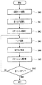
図20は図12のマスク生成部303によりマスクバッファ304に格納される上記マスクデータ(マスクパターン)3201、3301、3401および3501の生成手順の一例を示す。
【0169】
まず、縦横16画素で各マスク値が「0」から「255」の値を持つ母マスクデータをマルチパスの走査回数に量子化する(ステップS50)。本例では4回の走査によるマルチパスプリントであり、各記録走査内での記録許容画素数を均等にしているので、ある記録領域に対する4回のパスでは、マスク値「0」から「63」を第1パスに、マスク値「64」から「127」を第2パスに、マスク値「128」から「191」を第3パスに、マスク値「192」から「255」を第4パスに割り当てることになる。
【0170】
次に、各走査に対応するマスクデータの記録許容画素をオンとする処理を行う(ステップS52)。すなわち、第1走査用マスクデータ3201上、ある記録領域の第1パスに割り当てられた位置の画素をオンとし、第2走査用マスクデータ3301上、当該記録領域の第2パスに割り当てられた位置の画素をオンとする。同様に、第3走査用マスクデータ3401および第4走査用マスクデータ3501についても、当該記録領域のそれぞれ第3パスおよび第4パスに割り当てられた位置の画素をオンとする。
【0171】
次に、各走査間でのプリント媒体搬送量に対応して、マスクデータをローテートする(ステップS52)。すなわち、マスクデータ3301を上に4画素分、マスクデータ3401を上に8画素分、マスクデータ3501を上に12画素分ローテートする。
【0172】
以上の実施形態によれば、マスク生成部303は、マルチパスプリント法における間引きパターンとして、任意のレベルで2値化された際に記録許容画素と非記録許容画素との配置が視覚的に好ましくなるようなドットの分散性の高い疑似周期的マスク配列からマスクパターンを生成するようにしたので、次のような作用および効果を奏する。すなわち、上記構成において、疑似周期的配列の母マスクデータは、一様乱数と比べて低周波成分が少ないため、繰り返しパターンの発生や粒状性の増加を防止するように働く。すなわち、ドットの分散性の高い疑似周期的配列の母マスクデータを用いることにより、短い周期の乱数を用いた場合に生じる繰り返しパターンや、一様乱数によるマスクを用いた場合に生じる粒状性の増加を防ぐことができるのである。
【0173】
なお、母マスクの生成のための手段は、必ずしも本実施形態のプリンタに予め組み込まれるものでなくてもよく、予め別体の母マスク生成装置により母マスクデータを生成し、結果の母マスクデータのみを本実施形態のプリンタの母マスクメモリ306に格納するものであってもよい。これについては後述する実施形態についても同様である。
【0174】
7.3 疑似周期的マスクの生成の他の例
上記実施形態では、特に上記式(1)を用いて擬似周期的配列の母マスクデータを作成したが、本発明に適用可能な擬似周期的配列のマスクは上式に限ったものではない。すなわち、疑似周期的マスク配列(疑似周期的配列の母マスクデータ)は、ランダムに初期記録許容画素位置を求め、当該求めたすべての記録許容画素位置に対して一定の斥力ポテンシャルを付与し、当該ポテンシャルの和が最小となる画素位置に新たな記録許容画素を設定する処理を、すべての画素が記録許容画素となるまで繰り返すことにより生成されるものであり、斥力ポテンシャルは、記録許容画素からの位置に従って減衰する関数で表されればよく、上記式(1)で示した関数に限られるものではない。
【0175】
また、上記実施形態では、母マスクデータを作成した上で各走査に適用される疑似周期的配列のマスクを生成した。これは、母マスクを一度作成すれば、マルチパスプリントのパス数が変更される場合にもそのパス数に応じたマスクの作成に直ちに対応できるという利点がある。
【0176】
これに対して、ある広がりを持つ領域に対して適用される疑似周期的マスクを直接的に生成することもでき、その実施形態について次に説明する。この実施形態は、パス数の変更に応じて新たにマスクを作成することにはなるが、上記実施形態が各スキャン毎に適用するマスクを変える(すなわち、4パスプリントの場合は図13〜図16の(b)に示す4種類のそれぞれがそれぞれのスキャンで適用される)のに対し、そのような変更を要さないためにプリントのスループット向上に資することができる。
【0177】
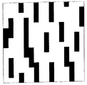
図22は本実施形態で適用する疑似周期的マスクの例であり、そのマスクエリアのサイズは縦(副走査方向)および横(主走査方向)についてそれぞれ256画素分の長さに対応したものとする。縦の長さは図11に示したヘッド上にあるノズルの数に一致しており、マスクは記録ヘッドに対し常に固定である。また、4パスプリントを行うものとし、各主走査間では図22において横線で区切った範囲(64ノズル分)を単位として記録紙が矢印の方向に搬送される。
【0178】
紙面上の同一プリント領域に対しては常に、マスクAを適用した往路プリント(1パス目)、マスクBを適用した復路プリント(2パス目)、マスクCを適用した往路プリント(3パス目)、マスクDを適用した復路プリント(4パス目)の順に記録がなされ、4回の記録走査を経て初めて当該領域の画像が完成する。また、マスクA〜マスクDは100%の記録データに対して補完を行う関係にあり、本実施形態の場合それぞれ25%ずつの記録率となっている。
【0179】
なお、本実施形態のマスクを作成ないし適用するための制御系の構成については、図12に示したものとほぼ同様のものとすることができるが、図12におけるブロック303および306に代えて、次のような作成処理等を行う機能ブロックを採用すればよい。また、記録に際してマスクを生成するのではなく、本実施形態のプリンタまたは別体のマスク生成手段(例えばホストコンピュータ)によって予め生成された複数のパス数の種類に対応した複数のマスクを格納しておき、実行するマルチプリントのパス数に応じたマスクを記録に際して適宜選択するものでもよい。さらに、ホストコンピュータから画像データを受け取る際に、パス数の指定と対応するマスクを受容し、記録に際してこれを用いる構成とすることもできる。
【0180】
図21は本実施形態によるマスクデータの作成手順の一例を示す。まず、縦64画素×横256画素のマスク領域Dのうち、最上部の縦16画素×横256画素の領域を縦64画素×横16画素の大きさを持つ16個のブロックに分割する。そして、各ブロック毎にそれぞれ1つ目の記録許容画素をランダムに決める(ステップS1601)。これを本実施形態のマスクの初期画素と決定する。これと同時に、この画素と位置的に対応するマスク領域A、BおよびC上の画素はドット形成がなされないようマスキングしてしまう(ステップS1602)。なお、初期画素の個数および選択領域はこれに限られず適宜定め得るのは勿論である。次の画素からは斥力ポテンシャルを用いて記録許容画素を決定していく(ステップS1603)。本実施形態で定義するポテンシャルは、上例と同様式(1)で示した関数で与えられるものとする。
【0181】
そして、複数の記録許容画素(本手順の開始直後では16個の画素)から得られるポテンシャルの和が注目画素のポテンシャルとなる。さらに、縦256画素×横256画素のマスクは縦方向および横方向に繰り返し適用されるので、隣接する領域(例えば縦方向では、マスク領域Dの最上部に対してマスク領域Aの最下部)からの影響も加味してポテンシャルの和を計算する。このように決められた各画素のポテンシャルのうち最小値を有するものを次の記録許容画素(本手順の開始直後では17番目の記録許容画素)として決定する(ステップS1604)。この処理に際しては既にマスキングされている画素は除外される。また、最小値を有する画素が複数存在する場合にはその中からランダムに記録許容画素を1つ決定する。
【0182】
さらに、マスク領域A〜Dのうち、この記録許容画素が存在する以外の領域内の対応位置の画素をマスキングし、再び、全画素位置についてのポテンシャルを計算する。以下、ステップS1602〜S1604の処理を全マスク領域の画素のうち25%が記録許容画素(ここでは16384個)となるまで繰り返す(ステップS1605)。
【0183】
このような処理にて作成されたマスクが図22に示したものである。この図と、特開平7−052390号公報に開示されたものに準ずるランダムマスクを示した図23とを比較すれば、視覚的な差を確認することができる。両者の差はドットの分散性にある。すなわち、図22のマスクは図23のマスクに比べて低周波成分が少なく分散性が高い。よって視覚的にはザラツキが少なく感じるのである。
【0184】
図24は図22の往路プリント(奇数番目のパス)のマスクデータの和を示しており、図25は復路プリント(偶数番目のパス)のマスクデータの和を示している。本実施形態の特徴は、各記録走査のマスク配列も分散性の高い擬似周期的配列となっているが、これらの図から明らかなように、往路プリントの和および復路プリントの和もそれぞれ同様の擬似周期的配列になっていることにある。
【0185】
本発明は記録走査毎のドット形成位置の誤差に対し、視覚的に画像弊害が感知されないような分割間引き用のマスクを提供することを目的の一つとしている。記録走査毎のドット形成位置のずれは使用しているマスクの形状が画像上に顕在化する現象となって現れるので、各記録走査毎のマスク配列が視覚的に好ましい状態であれば、画像上、ずれが感知されにくい。双方向プリント時のレジストレーションのずれも同様である。往路プリント時のマスクと復路プリント時のマスクとがそれぞれ視覚的に好ましい状態であれば、画像上、ずれが感知されにくいのである。
【0186】
図26は図23に示したランダムマスクの往路プリント(奇数番目のパス)のマスクデータの和を、図27は復路プリント(偶数番目のパス)のマスクデータの和を示している。これらの図と図24および図25とを比較すれば、両者の差を確認できる。すなわち、図24および図25の状態は図26および図27に示すものと比べて低周波成分が少なく分散性が高い。よって全体的にざらつきが少ないのである。
【0187】
一般に、記録するべきドットの配列は量子化の手法により異なるが、なるべく視覚的に目障りにならないように配置される。特に最近要望されている写真調画質を得るには画像の滑らかさが追求されるので、誤差拡散法や特許第2622429号に記載の青色雑音マスクを用いた2値化法が好ましいとされる。従って、2値化されたオリジナルの画像データ自体が低周波成分の少ない状態であることが多い。しかしながら、マルチパスプリントを行う際に記録走査間でドット形成位置のずれ(インクジェットプリント方式ではインク着弾位置のずれ)が生じると、本来の好ましい配列が崩れてしまうことになる。従って、記録走査毎の間引き配列(マスクパターン)自体を視覚的に好ましくしておくことで、仮にずれが生じても、目障りにならない、すなわちざらつきの少ない画像を得ることができる。
【0188】
ここで注意すべきことは、視覚的に好ましいマスクのドット配列が、視覚的に好ましい量子化後のドット配列(プリントのために入力される2値化画像データないしは2値化処理のためのマスク配列)と、全体的あるいは部分的にでも同期しない(同じ配列にならない)ことである。もし同じ配列になってしまうと、その部分のみ分割記録が行われず、マルチパス本来の目的が達成されなくなってしまう。本実施形態のマスク構成は2値化後のドット配列に同調せず、各記録走査で均等(記録画像の25%ずつ)にデータを分割プリントすることにより、好ましい効果を得ている。
【0189】
双方向のドット形成位置のずれが常にずれていれば、画像全体にざらつきが生じる。本実施形態のような疑似周期的マスクは、ずれに起因して顕在化するテクスチャが目立たないものであるので、画像のざらつきを低減できる。しかし疑似周期的マスクを適用しない場合でも、特開平10−329381号公報に記載されたようなドット形成位置合わせ(レジストレーション)処理を行えばざらつきの発生を回避できる。しかしながら、液体であるインクを付与することによりプリントを行うインクジェットプリント方式では、コックリングの影響などにより紙面が部分的に浮き上がることがあり、レジストレーションのための調整適正値が局所的に他の部位と異なってしまうことがある。このような場合は、浮き上がっている部分のみ画像がざらついて感じられることがあり、部分的なざらつきであるが故に余計に確認されやすい。
【0190】
本実施形態のような疑似周期的マスクは、双方向プリントのドット形成位置ずれが生じていても画像上に顕在化するテクスチャがそもそも目立たず、局所的にドット形成位置ずれが生じた領域と、そうでない領域との差が目視で感じられないようにできるので、コックリング等に起因したむらの影響が現れにくいものである。
【0191】
なお、ここでは双方向のドット形成位置の全体的なずれ、ないしはコックリング等に起因した局所的なずれによるむらの抑制に対して本実施形態のような疑似周期的マスクが効果的であることを説明したが、その他の要因によるずれに対しても効果的である。
【0192】
例えば、シリアルプリント方式での各記録走査間の誤差は、主走査方向の誤差と副走査方向の誤差とに分類される。主走査方向の誤差はすでに説明した双方向のドット形成位置のずれやコックリングによる局所的なむらのほかに、キャリッジ走査系(駆動源であるモータや伝動機構など)あるいは走査制御系(移動検出用のエンコーダなど)の精度に依存するキャリッジの速度むら等が存在する。また、副走査方向の主な誤差には記録走査毎の搬送量のばらつきや、紙浮きなどに起因したものがある。特にプリント媒体が搬送部材に完全に支持されていない状態(例えば図45におけるフィードローラ対にプリント媒体先端部が挟持されるまでの間や、給紙ローラ対から後端部が外れた以降)など、紙の押さえが不安定な個所で搬送量のばらつきや紙浮きなどが起きやすい。本実施形態で示したような疑似周期的マスクは2次元方向に低周波成分が少なく分散性が高いものであるので、このような副走査方向の誤差にも効果的に対応できるマスクである。
【0193】
すなわち、本実施形態によれば、双方向プリントのマスクにおいて、各記録走査のマスク配列が視覚的に好ましい擬似周期的配列になっていることにより、記録走査毎の主走査方向や副走査方向の誤差によるドット形成位置ずれが全体的あるいは部分的に起こっても、画像品位の低下を最低限に抑制することが可能となる。加えて、奇数パスの和(あるいは偶数パスの和)から構成されるマスク配列もやはり視覚的に好ましい擬似周期的配列になっていることにより、双方向レジストレーションのずれやコックリングむらの抑制に対し更に有効なプリント方法を実現できる。
【0194】
7.4 その他のマスクの形態
以上の実施形態では、プリント画素と非プリント画素との配置が視覚的に好ましくなるようなドット配列パターン、すなわち低周波成分が少なく分散性の高いドット配列パターンをもつマスクとして、斥力ポテンシャルを用いて作成した擬似周期的マスクについて説明した。しかし同様の効果を得るものであれば、他の形態のマスクを用いることもできる。例えば特許第2622429号に開示されているような青色雑音(ブルーノイズ)特性をもった二値化後の配列データを、分割記録のための間引き用のマスクと設定してもよい。
【0195】
また、ランダムマスクについて適用された特開平7−125311号公報に記載されたもののように、記録走査毎にマスクにオフセットをかけるようにしてよい。
これらのことは以下の実施形態でも同様である。
【0196】
8.集中画素マスクへの疑似周期的配列の適用
次に、本発明の他の実施形態を説明する。本実施形態も4パスの双方向プリントとするが、ここでは前述の特開平6−22106号公報に記載された集中画素マスクの効果も取り入れ、横4画素×縦1画素からなる集中画素を単位とした視覚的に好ましい擬似周期的配列のマスクとする。
【0197】
図28は本実施形態で用いる集中ドットを示し、横方向4ドット×縦方向1ドットの構成を単位とした画素配列で記録を行う。擬似周期的マスクを作成する場合は、マスク領域も横4画素、縦1画素単位の格子に分割する。1つの格子が1つのポテンシャルを持つとして、格子ごとのポテンシャルでマスクを作成する。さらに本実施形態では、上記条件で作成されたマスクに対し、主走査方向(横方向)にランダムなずれを生じさせる。
【0198】
図29は本実施形態で用いるマスクの作成手順の一例を示したフローチャートである。本実施形態では、横4画素×縦1画素の集中画素としているのでまず始めに全領域を4×1単位に分割する(ステップS1701)。以後、記録許容画素の決定やマスキングはこの単位で設定される。続くステップS1702では、図21の処理とほぼ同様に初期の記録許容画素を領域D内にランダムに決定し、領域A〜Cの同じ画素位置はマスキングする(ステップS1703)。その後すべての画素位置に対し、前述の実施形態と同様に斥力ポテンシャルを計算する(ステップS1704)。ここでも第1実施形態と同様の計算式を用いるが、本実施形態では常に4×1画素の単位で記録/非記録状態が決定されるので、記録許容画素のポテンシャルも4画素の和によって決定する。このように決められた各集中画素のポテンシャルのうち最も小さい集中画素位置を次の記録可能集中画素として決定する(ステップS1705)。この処理に際し、既にマスキングされている位置の集中画素は除外される。また、最小値を有する集中画素が複数存在する場合にはその中からランダムに1つ決定する。
【0199】
さらに、マスク領域A〜Dのうち、この記録可能集中画素が存在する以外の領域内の対応位置の集中画素をマスキングし、再び、全集中画素位置についてのポテンシャルを計算する。以下、ステップS1703〜S1705の処理を全マスク領域の集中画素のうち25%が記録可能な集中画素(ここでは4096個)となるまで繰り返す(ステップS1706)。
【0200】
さらに、本実施形態ではでき上がったマスクの256本のラスタを互いに左右にランダムにずらす(ステップS1707)。
【0201】
図30は以上の手順により作成されたマスクの拡大図を示す。また、図31はステップS1706までの手順で4×1の集中画素を得たまま、ステップS1707の処理を行わずランダムなずれを生じさせない場合のマスクの拡大図である。これらの図から明らかなように、図31は4×1の集中画素が縦方向および横方向に互いに1画素の単位で隣接していないのに対し、図30では互いに縦方向に数画素ずつ接しながら配列されている。図30のような配列は、双方向プリントのドット形成位置ずれのみでなく、各記録走査において何らかの要因による横方向のドット形成位置ずれに対しても効果がある。すなわち、コックリングや双方向プリントのドット形成位置ずれが生じていなくても、各記録走査間では互いに多少のずれが生じてしまうことがあるが、本実施形態は特に主走査方向のドット形成位置ずれによる画像品位低下の弊害をより積極的に防止することができる。
【0202】
本実施形態は、特開平6−336016号公報に記載の効果と、前述の実施形態で説明した擬似周期的マスクを適用した場合の効果とを併せ持つものである。
【0203】
記録走査毎の誤差は、同一記録走査で形成されたドット間ではなく、異なる記録走査間で形成されたドット同士の重なりもしくは離隔となって現れる。従って、集中画素を大きくすることで、記録走査毎のずれの影響が現れる部位(以下、誤差点と称す)を少なくできる。本実施形態では特に、主走査方向の誤差対策を意識しているので、横方向に長い4×1の集中画素を用いる。これにより、集中画素を適用しない前述の実施形態に比べ誤差点の数を1/4に抑えることができる。
【0204】
ここで、図30および図31の配列は両者とも確かに誤差点の数を減らすことができている。しかし、それらが図31の矢印で示す方向の同一ラインに存在すると、その誤差はむしろ強調され、目に付きやすい。よって本実施形態では、図30のように集中画素をランダムにずらすことで誤差点をラスタ毎に分散させているのである。
【0205】
以上では、横方向の誤差(ノイズ)に対処するために横方向に長い集中画素を用い、かつ集中画素を横方向にずらす例を説明した。しかし、本実施形態はこれに限るものではない。すなわち縦方向のノイズに強くすることに重点をおくならば、縦方向に長い集中画素を用い、集中画素を縦方向にランダムにずらせば本実施形態の効果は十分得られる。
【0206】
図32にその例を示す。ここでは1×4の集中画素をランダムに縦方向にずらした4パスプリント用のマスクを部分的に拡大して示している。図30と同様に誤差点が分散されているので、その部分が目立ちにくい。
【0207】
さらに、上述したようなプリント媒体の先端部および後端部に関しての搬送誤差対策が要望され、他の領域はむしろ主走査方向の誤差対策が必要な場合には、プリント媒体上の部分に応じて適用するマスクを切り替えてもよい。また、プリント媒体の種類によっても誤差の現れ方は大きく異なるので、プリント対象となるプリント媒体よってマスクを切り替えるようにしてもよい。
【0208】
また、本実施形態でも前述の実施形態と同様に、往路プリントに適用されるマスクデータの和(または復路プリントに適用されるマスクデータの和)のドット配列が4×1単位の視覚的に好ましい擬似周期的配列になるようにしてもよい。これによれば前述の実施形態と同様に、双方向ドット形成位置ずれに対しより有効に対応できる効果がある。
【0209】
さらに別の構成として、往路プリントに適用されるマスクデータの和(または復路プリントに適用されるマスクデータの和)が8×1の集中画素の配列を形作る構成を取ってもよい。このようにすると往路プリントと復路プリントの誤差点を半減することができ、別の角度から双方向むらへの効果が期待できる。
【0210】
以上の実施形態によれば、m×nの集中画素を単位とした視覚的に好ましい擬似周期的配列のマスクを作成し、かつ各集中画素が互いに横方向あるいは縦方向にランダムにずらして配列させることにより、主走査方向あるいは副走査方向の誤差に強い分割間引きを実現することが可能となった。
【0211】
次に、従来技術で説明した特開平6−22106号公報や特開平10−235852号公報に開示された技術を改良し、双方向プリントによる色むらや弊害をより低減させた実施形態について説明する。
【0212】
m×nの集中ドットサイズを大きくすることにより色むらは低減されるが、その効果が得られる程度の集中ドットはかなり大きく、写真画質には向かないことはすでに述べた。しかし本発明者らは、ここにおいても視覚的に好ましい擬似周期的マスクに従って配列すれば、画像弊害が低減されることを確認した。
【0213】
図33はこの8×4の集中ドットを用いた本実施形態の擬似周期的マスクを示す。8×4という大きさにもかかわらず、全体的に分散配列されているので視覚的には好ましい。
【0214】
図34は同じ集中ドットをランダムに配列した例である。ここでは、8×4の集中ドット自体よりもむしろこれらの配列が不均一であるので、集中して固まって配列してしまった部分とそうでない部分とでの差が激しく、ざらついて感知される。これに対し図33では8×4の集中ドットが比較的均等な距離を置いて配置されているので、特に局所的に密度の高い部分や低い部分が存在しない。本実施形態は双方向プリントを行うので、ここで示す黒部分と残る白い部分がそれぞれ往路の色と復路の色で記録されることになる。往路の色と復路の色に若干の差が存在することはすでに述べた。その上でそれぞれの色がこの図に示すように配列すると、明らかに図33のマスクを適用した方がざらつきが少なくなる。すなわち、擬似周期的配列のマスクを用いれば集中ドットが大きいことによる弊害も緩和されるのである。換言すれば、ざらつき感に余裕がある限り、さらに集中ドットのサイズを大きくすることもできるので、双方向プリント時に発生する色むらに対してより効果を発揮できるのである。
【0215】
9.マルチパスプリントにおける記録データ数の制御への適用
9.1 マルチパスプリントにおける記録データ数の制御
前述した特開平6−22106号公報に記載の発明は、記録走査方向の違いに起因する色むらは各記録走査ごとのインク被覆率(はみ出し率)に依存することに着目し、各走査で着弾される紙面上のインク被覆率をなるべく均等にすることを目的としたものである。そしてその目的を達成するための手段として、同一記録走査で記録されるドット同士を集中ドットとしてm×n画素を固めて記録していた。しかし、被覆率を均等にする目的は、集中ドットを用いずに、各記録走査での記録データ数の制御をによって達成することもできる。そして、記録データ数の制御に際して、低周波成分が少なくドット分散性の高いすなわち視覚的に好ましいマスクを適用することができ、以下ではその実施形態について説明する。
【0216】
まず、その前提として、記録データ数の制御について述べる。
【0217】
先に図49を用いて2回の記録走査(2パス)で画像を完成させる構成を例に挙げてマルチパスプリント法について説明したが、ここではまず8パスのマルチパスプリントについて説明する。8パス程度のマルチパスプリントを行えば、多くの記録媒体では双方向プリントを行っても色むらは殆ど発生しない。しかし、記録媒体の種類によっては発生するものもあるし、特に最高品位の画像が要求されるモードでは厳しく評価される。
【0218】
各記録走査で記録データを均等に分割する方式では、8パスプリントの場合は各パスにつき12.5%のデューティずつの記録が行われる。一方、図11に示した1200dpiの解像度のヘッドを用いてプリントを行う場合、紙面上での1画素は約21μm四方の領域となるが、本実施形態で用いるヘッドから吐出されるインクの1ドロップは約4plであり、紙面上では直径約45μmの円形ドットを形成する。このとき、1ドットの面積は1570μm2となり、1画素領域の21×21=441μm2よりはるかに大きくなる。このようなヘッドを用いて8パスプリントを行う際に従来のランダムマスク法を取り入れると、1パス目のインク被覆率は12.5%×1570/441≒45%となり、全体の1/2近くの紙面が埋め尽くされてしまう。次いで2パス目では1パス目と同等の12.5%のデータが記録されるが、紙面上では残された100−45=55%の中での45%となるので、55×45/100≒25.0%となり、同じ12.5%のデータ記録率でも被覆率としてはかなり削減された値となる。これに従い、3パス以降の被覆率はさらに減少していく。
【0219】
発明者らは、1パス目および2パス目すなわち最初の2回の記録走査での被覆率が45+25.0=70%となるので、8パスのマルチパスプリントでの優先色は、ほぼ最初の2パスで決定されてしまうことに着目した。双方向プリントの場合、1パス目と2パス目との記録方向は逆になるので、1パス目が往路プリントであったならば往路で最初に記録されたインクが、1パス目が復路であるならば復路で最初に記録されたインクがそれぞれ優先色になる。3パス〜8パスまでは残り約30%の白紙領域に対する効果しか関与せず、色むらにはほとんど関係していない。すなわち、最初の2パスで色むらによる画像品位低下が生じているのであって、換言すればこの最初の2パスでの色むらを抑制することができれば、画像全体の色むらによる弊害を著しく低減できるのである。
【0220】
発明者らは、1パス目と2パス目とのデータ記録率の和は12.5×2=25.0%に固定しながら、1パス目の被覆率と2パス目の被覆率との割合をほぼ同等にすることを目的として、1パス目の記録データを削減し、その分2パス目の記録データを増加させる実験を行った。計算上、2パス目までの被覆率が70%であるので、1パス目ではその半分の35%の被覆率となるようにデータ記録率を制御すればよい。この場合、逆算すれば35×441/1570=9.8%となるので、1パス目で約10%、2パス目では25−10=15%のデータ記録率とすればよいことになる。但しこの計算においては、同一記録パスで記録するドットは互いに隣接しないことを前提としている。
【0221】
図35は、1パス目と2パス目とのデータ記録率を1%刻みで変化させて実験した場合の色むらの評価結果を示す。色むらの目立ちやすい記録媒体を用いての実験結果であるが、1パス目のデータ記録率を9〜11%とすれば色むらはほとんど問題なくなり、10%では全く問題ないという結果が得られた。これは計算値とほぼ一致した答えである。
【0222】
図36は上記した内容を適用して実施した8パスプリントによる記録結果を示す。本実施形態で用いるヘッドは、上述のように実際には各色256個のノズルを有しているが、ここでは簡単のため、32個のノズルでシアンとイエローとからなるグリーン画像を記録する場合について説明する。
【0223】
本実施形態は8パス記録であるので、1度の記録走査でプリントできる全32画素領域を4画素ずつの記録領域に分割し、各記録領域について8回の記録走査で画像を完成させる。どの画像領域においても、最初に1パス記録領域の4つのノズルによってドットが記録される。一般的な8パス記録では、記録領域の12.5%の画素に往路あるいは復路で記録がなされるが、本実施形態の1パス記録領域では10%に記録データ率を低減している。図13では、ある往路の記録走査が終了した時点の画像記録状態を表している。1パス記録領域では全画像データのうち、10%の画素についてシアンが優先色のドットが記録されている。この段階で被覆率は約35%となっている。
【0224】
隣接する2パス記録領域では、新たに15%の画素データの記録がなされている。この領域では、既に前回の復路記録走査で着弾されたドットが10%程記録されているが、これらのドットはイエローが優先色のドットである。今回新たに記録された15%のドットが先に記録されたドットに重複した場合には、裏側へ潜り込み、優先色は1パス目のドットとなっている。ここまでの記録結果から明らかなように、シアンが優先色のドットとイエローが優先色のドットとがほぼ半分の割合で均等に分布しているとともに、2パス記録までの段階で画像領域の殆とが埋め尽くされている。
【0225】
3パス以降の記録領域では全て12.5%ずつのデータが記録されており、ドットの優先色は上記規則にしたがって背面に潜り込んでいる。3パス以降は残り30%の白紙領域をうめていくが、殆どのドットが2パスまでのドットの背面側に潜り込むので、ドットの優先色がシアンであろうとイエローであろうと、画像全体の優先色には殆ど影響を及ぼしていない。
【0226】
次に、4パスプリントにおいて上述と同様に記録データ数を制御する場合について説明する。上述のように従来の方法では各記録走査で記録データを均等に分割するので、4パスプリントの場合は25%デューティーずつの記録が行われる。ここで、従来のランダムマスク法を取り入れると、1パス目のインク被覆率は25%×1570/441≒89%となり、殆どの紙面が埋め尽くされてしまう。次いで2パス目では1パス目と同等の25%のデータが記録されるが、紙面上では残された100−89=11%の中での89%となるので、11%×89%≒10%となり、同じ25%のデータ記録率でも被覆率としては1パス目に比べかなり削減されてしまう。これに従い、3パス以降の被覆率はさらに減少していく。
【0227】
そして、4パスプリントの場合は1パス目と2パス目すなわち最初の2つのパスで被覆率が89+10=99%となるので、4パスプリントでの優先色は、ほぼ最初の2パスで決定されてしまうことになる。また、双方向プリントを行う場合には1パス目と2パス目との記録方向は逆になるので、1パス目が往路プリントであったならば往路で最初に記録されたインクが、1パス目が復路であるならば復路で最初に記録されたインクがそれぞれ優先色になるのも上述と同様である。そして、3パス目および4パス目では残り約1%の白紙領域に対する効果しかなく、色むらにはほとんど関係していない。すなわち、最初の2パスで色むらによる画像品位低下が生じているのであって、換言すればこの最初の2パスでの色むらを抑制することができれば、画像全体の色むらによる弊害を著しく低減できるのである。
【0228】
そこで、4パスプリントの場合は、1パス目と2パス目とのデータ記録率の和は25×2=50%に固定しながら、1パス目の被覆率と2パス目の被覆率との割合をほぼ同等にすることを目的として、1パス目の記録データを削減し、その分2パス目の記録データを増加させればよい。計算上、2パス目までの被覆率が99%であるので、1パス目ではその半分の49.5%の被覆率となるようにデータ記録率を制御すればよい。この場合、逆算すると49.5×441/1570=13.9%となるので、1パス目で約14%、2パス目では50−14=36%のデータ記録率とすればよいことになる。
【0229】
9.2 疑似周期的配列の適用
以上のようなマルチパスプリントにおける記録データ数の制御に際し、本実施形態では、非記録許容画素と記録許容画素とを視覚的に好ましい状態に配列した擬似周期的マスクを導入する。
【0230】
例えば、図12〜図20について説明した実施形態の疑似周期的マスクを適用する場合には、次のように行えばよい。
【0231】
すなわち、同一記録領域に対して4回の走査によるマルチパスプリントを行い、かつ各走査での記録データ数の制御を行う場合、図20の手順を一部変更することで各走査に疑似周期的マスクを適用することができる。
【0232】
母マスクが縦横16画素で各マスク値が「0」から「255」の値を持つ構成に対して、マスクデータをマルチパスの走査回数に量子化する。前述の4パスプリントでは各記録走査内での記録許容画素数を均等にしていたので、ステップS50においてはマスク値「0」から「63」を第1パスに、マスク値「64」から「127」を第2パスに、マスク値「128」から「191」を第3パスに、マスク値「192」から「255」を第4パスに割り当てた。
【0233】
しかし、本実施形態では記録紙上のインク被覆率を第1パスと第2パスとで均等にするために、上述のように第1パスの記録数を全体の14%、第2パスの記録許容画素を全体の36%、第3および第4パスについてはそれぞれ25%とする。よって、ステップS50の処理において、マスク値「0」から「35」を第1パスに、マスク値「36」から127を第2パスに、マスク値「128」から「191」を第3パスに、マスク値「192」から「255」を第4パスに割り当てるようにすればよい。
【0234】
このような実施形態によれば、まず基本的に、マルチパスプリント法における間引きパターンとして、任意のレベルで2値化された際に記録許容画素と非記録許容画素との配置が視覚的に好ましくなるようなドットの分散性の高い疑似周期的マスク配列からマスクパターンが生成されるので、次のような作用および効果を奏する。すなわち、上記構成において、疑似周期的配列の母マスクデータは、一様乱数と比べて低周波成分が少ないため、繰り返しパターンの発生や粒状性の増加を防止するように働く。すなわち、ドットの分散性の高い疑似周期的配列の母マスクデータを用いることにより、短い周期の乱数を用いた場合に生じる繰り返しパターンや、一様乱数によるマスクを用いた場合に生じる粒状性の増加を防ぐことができるのである。
【0235】
以上の通り、前述の実施形態の如く4パスプリントですべての記録走査で25%ずつに均等に記録データ数を分割する(均一の記録デューティとする)のみならず、各記録走査間の記録デューティに差をもたせても所期の目的は達成できる。
【0236】
なお、本実施形態が有効であるのは、少なくとも4パス以上の分割記録を行う場合であると考えられる。もちろん、2パスプリントでも色むらに対する理論上の効果はあるが、分割記録法のもうひとつの目的であるノズルばらつきの濃度むらや、つなぎすじを目立たなくするという効果は、各記録走査でデータ記録率をなるべく均等にすることによって得られるものであるからである。2パスプリントの場合に本発明を適用すると、ほとんど1パス目では記録できず、2パス目で記録が行われることになりかねない。こうなると、分割記録の本来の効果が減殺されてしまうことになる。
【0237】
これに対し、4パス以上のマルチパスプリントであれば、1パス目と2パス目との記録率に多少の偏りが生じたところで、残りの複数パスで均等に分割されていれば問題は生じない。1パス目および2パス目は色むら低減のための記録走査であり、3パス目以降はノズルのばらつきによるむらおよびつなぎ筋対策のための記録走査であると意味付けできるのであり、これらが相俟って高品位の写真画質を達成する上で十分な効果が期待できるのである。そして、特に本実施形態で用いたような、実際に記録されるドット面積が1画素領域よりも大きい場合に効果が現れる。
【0238】
また、マルチパス記録はパス数が多いほど画像品位が向上する一方、プリント時間は長くなる。そこで、マルチパス記録を行わない1パスモード、2パスから8パスまでのマルチパスモードでの記録を可能とし、記録媒体の種類や用途に応じてプリントモードを適宜切り替えることができるようにすることもできる。
【0239】
また、実際の記録動作における各パスの記録データ比率の規定ないしマスクデータをマルチパスの走査回数に量子化する処理(ステップS50)等は、CPUE1001等のソフトウェアとして行うもののほか、適宜のハードウェア、例えばASIC E1006の回路構成の一部として設けておくことができる。
【0240】
例えば、図9において、選択されたモードについて上述のように各パスの記録データ比率ないし上記量子化を行うためのデータを展開用データバッファE2016に格納しておき、記録動作の進捗に応じてデータ展開DMAコントローラ E2015がパスの番号を管理し、その番号に応じたマスクパターンにて、プリントバッファE2014に展開されている記録データがマスキングされるようにすることができる。
【0241】
10.記録データ数の制御および集中画素マスクへの疑似周期的配列の適用
次に、記録データ数の制御に擬似周期的配列を適用するとともに、さらに前述の特開平6−22106号公報に記載された集中ドットマスクの効果も取り入れる実施形態について説明する。
【0242】
なお、ここでも擬似周期的マスクを用いた4パスプリントを行うものとし、図28に示したような横方向4ドット×縦方向1ドットの集中ドットを用いるものとする。また、擬似周期的マスクを作成する場合は、母マスクサイズの中身も横4画素、縦1画素単位の格子に分割する。1つの格子が1つのポテンシャルを持つとして、格子ごとのポテンシャルでマスクを作成する。
【0243】
複数ドットが隣接していることが前提であれば、各ドットの重なり合った領域は被覆率の計算上互いに打ち消され、その分小さい値となる。本実施形態でも前述した実施形態と同様の記録装置を用いるとすれば、1つの集中ドットの被覆率は約64%となる。但し、ここではm×n=4×1の集中ドットの単位同士は互いに隣接しないことを前提としている。被覆率が少ない分、1パス目のデータ記録率を大きく設定することができる。
【0244】
4パスプリントに際し均等にデータを分割すると各記録走査での記録率は25%となり、4×1単位の集中ドットで記録を行った場合、1パス目の被覆率は64%、2パス目の被覆率は23%となる。また、2パス目までの被覆率は87%となり、やはり最初の2パス目まででほとんど色むらが決まることになる。
【0245】
この被覆率を等分するためには、1パス目のデータ記録率を16%、2パスの記録率を34%とすればよい。
【0246】
図37はこの法則に従って記録を行った場合の模式図である。本実施形態で用いるヘッドは図11に示すものであるが、ここでは簡単のため32個のノズルによってシアンおよびイエローからなるグリーン画像を記録する状態について説明する。
【0247】
本実施形態は4パス記録であるので、1度の記録走査でプリントできる全32画素領域を8画素ずつの記録領域に分割し、各記録領域について4回の記録走査で画像を完成させる。どの画像領域においても、最初に1パス目の記録領域の8つのノズルによってドットが記録される。従来の4パス記録では記録領域の25%画素に往路あるいは復路で記録がなされるが、本実施形態の1パス記録領域では記録データ率を16%に低減させている。図37はある往路の記録走査が終了した時点での画像記録状態を表している。1パス記録領域では、全画像データのうち、16%の画素についてシアンが優先色であるドットが記録されている。この段階で、被覆率は約44%となっている。
【0248】
隣接する2パス記録領域では、新たに34%の画素データの記録が行われている。この領域では、既に前回の復路記録走査で着弾されたドットが16%程記録されているが、これらのドットはイエローが優先色のドットである。今回新たに記録された34%のドットがこれら先に記録されたドットに重複した場合には、裏側に潜り込み、優先色は1パス目のドットとなっている。3パス以降の記録領域では全て25%ずつのテータが記録されており、ドットの優先色は上述と同様の規則に従って背面側に潜り込んでいる。
【0249】
この記録結果から明らかなように、2パスまでの段階で画像領域の殆どが埋め尽くされている。従って、3パス以降のドットの優先色がシアンであろうとイエローであろうと、画像全体の優先色には殆ど影響を及ぼしていないのである。このように、従来の集中ドット記録法に擬似周期的配列を適用しつつ、1パス目および2パス目のデータ記録率を被覆率が均等になるように制御することにより、色むらのない双方向プリントが実現可能となる。このように、従来例と同様の集中ドット記録法を用いながらも、1パス目および2パス目のデータ記録率を、被覆率が均等になるように制御することにより、少ない分割数で色むらのない双方向プリントが実現可能となる。
【0250】
すなわち、本実施形態によれば、集中ドット単位での擬似周期的マスクを用いつつ、1パス目と2パス目のデータ記録率を制御することにより、双方向プリントに起因するテクスチャーや色むらのない滑らかな画像を出力することが可能となった。
【0251】
図38は4パスプリントにあって1パス目と2パス目との被覆率を同等にした場合の各集中ドット形態とデータ記録率との関係を示す。もし、各記録走査でのデータ記録率を25%に固定したまま、集中ドット法のみで色むらの発生を防止しようとすると、集中ドットの大きさはかなり大きな値になってしまう。逆に、第1実施形態と同様にデータ記録率のみを制御して4パスプリントを実施しようとすると、1パス目のデータ記録率は14%となり、マルチパスプリントの筋むら抑制の効果が少なくなる傾向にある。
【0252】
本発明および本実施形態が実現している写真画質では、粒状感や筋むらが人間が視覚で認識できる解像度限界を超えている。換言すれば、当該視覚解像度以上あればそれ以上の高解像を求める必要性も少ない。既に説明したように、集中ドットを大きくすることは、それだけで被覆率を小さく設定でき、ひいては色むら発生防止のために行っていたマルチパス数を少なくできるので、記録のスループットを向上する観点からも効果的である。すなわち、集中ドットの構成単位を視覚的に感知できない程度に設定しておく一方、データの記録率を適切に設定することによって、マルチパス記録の効果が十分得られるのであれば、色むらもなく、分割記録数も最低限度に留められた双方向プリントが可能となる。
【0253】
なお、ここでは各記録走査のすべてで4×1画素の集中ドットマスクを用いたが、1パス目(あるいは奇数番目のパス)のみ集中ドットマスクを用い、残りの3パス(あるいは偶数番目のパス)では1ドット単位のランダムマスクを用いるようにしてもよい。記録ドットの被覆面積を小さくしなければならない記録走査は1パス目(あるいは優先色である奇数番目のパス)のみであり、2パス目以降(あるいは偶数番目のパス)はむしろ大きく設定すべきである。このようにすれば、実際に記録される集中ドットの数も減り、画像全体もより滑らかになることが期待される。
【0254】
また、上述の各実施形態でそれぞれ例示した記録方法を複合的に採用した構成とすることもできる。すなわち、例えば図36で示したような記録を行う8パスモード(第1モード)と、図37で示したような集中ドットを用いる4パスモード(第2モード)とを具備した構成とすることもできる。そして、ユーザの所望に応じて各モードを切り替え、選択的に使用できるようになし、例えば画質を優先したい場合には8パスモードを、あるいは速度を優先したい場合には集中ドットを用いる4パスモードを選択することで、所望の記録物を適宜得ることができるようになる。
【0255】
さらに、各記録走査のみでなく同一記録走査内でもいくつかの領域に分割し、各記録領域内で間引き率が異なるようにマスクを適用するものでもよい。
【0256】
図39(a)および(b)はその例を示す。ここでは2×1の集中画素を用い、横方向のずらしを入れ、かつ4パスの各領域を更に8分割し、それぞれの記録デューティ値を異ならせている。各領域の記録デューティの状態が同図(a)であり、これに従って作成されたマスク配列が同図(b)に示すものである。
【0257】
このようなグラデーションをつけたマスクの基本的構成は本出願人による特願2000−252938号に述べられている。これはランダムマスクを適用したものであり、特に小粒径のインクを吐出する多数のノズルを具備した形態の記録装置で起こるヘッド端部の白スジに対し有効となることが開示されている。
【0258】
このようなグラデーションマスクに疑似周期的配列を適用する場合には、作成するマスクの各記録領域で記録許容画素数に上限を設け、その値に達したときにその領域に対しマスキングを行ってしまえば、図21あるいは図29で説明した手順により作成することができる。
【0259】
次に、図33で説明した実施形態の変形例を説明する。この例は写真画像を実現する記録装置であり、図11に示したようなヘッドを用いて、シアン、マゼンタ、イエローおよびブラックの濃インクのほかに、淡シアン(LC)および淡マゼンタ(LM)の淡インクを加えた6色で画像を形成するものとする。
【0260】
図40および図41は本例で用いるマスクを示す。本例では、シアン、マゼンタおよびブラックの3色については図40で示したマスクを、また淡シアン、淡マゼンタおよびイエローについては図41のマスクを用いる。図40は1パス目のプリントデューティが2パス目よりも低く、図41では逆に2パス目のデューティの方が低くなっている。
【0261】
すでに説明した色むらに関しては、1パス目と2パス目の被覆率の差が大きな要因になるので、8×4の集中画素を用いるのみでは色むらへの効果が不充分な場合に被覆率が多くなりやすい1パス目のプリントデューティをあらかじめ低くしておくと、色むらがより低減される。よって、ここでは色むらのより目立ちやすい濃インク(シアン、マゼンタ、ブラック)のみ図40のマスクを用いる。
【0262】
淡インクやイエローインクは他の3色に比べ一般に記録ドット数が非常に多い。この場合、色むらの問題以前に、1パス目と2パス目との記録間隔の差が問題となってくる。2パスの双方向プリントを行う以上、どうしてもプリント媒体の左右端で1パス目と2パス目との間の時間が大きい領域と小さい領域とが副走査幅毎に交互に存在してしまう。この場合、同じ記録マスクを適用し、同じ記録方法でプリントを行っても時間間隔が大きい方が小さい方よりも濃度が高くなることが確認されている。この濃度差はプリントデューティが高いほど大きく現れるので、濃インクよりも記録ドット数の多い淡インクのほうがより顕著に現れる。
【0263】
この時間差むらを低減させるためには、2パス目に記録するドット数をなるべく少なくし、時間差の影響を及ぼさないようにするのが効果的である。よって本実施形態では、記録デューティの高いイエロー、淡シアン、淡マゼンタのみ1パス目の記録率を高くし、2パス目をなるべく低くする構成を取っているのである。
【0264】
しかし、本実施形態の効果はこのデューティ分布に限定されるものではない。各プリントモードや各色インク毎に現れる弊害は異なるので、それぞれに適したプリントデューティのマスクを独立に設けても、それぞれが視覚的に好ましい擬似周期的マスク配列を用いている限り、本実施形態は効果的である。すなわち、集中ドットの目立ち易さや色むら自体の自立ち易さは、記録媒体や記録画像の種類によって異なるものである。従って高品位の写真画像の形成を目的としたプリントモードにおいても、記録媒体等の条件毎に集中ドットの大きさやデータ記録率を適宜調整することができる。
【0265】
いずれにせよ、本実施形態によれば、集中ドット単位でのマスクを用いつつ、1パス目と2パス目とのデータ記録率を制御して双方向記録を行うことにより、色むらもなく滑らかな画像をより高速に形成することが可能となった。
【0266】
11.インターレース記録法への疑似周期的マスクの適用
次に、擬似周期的配列のマスクパターンをインターレース記録によって画像を完成させている構成のシリアルプリンタに応用した実施形態について説明する。
【0267】
米国特許第4920355号や特開平7−242025号公報に開示された技術のように、マルチノズルの配列構成は低解像度にしておきながら、各記録走査ごとの紙送り量をノズル列幅以下の所定の画素数分にすることにより、高解像度の記録を実現しているものもある。このような記録方法を以下インターレース記録法と称す。
【0268】
図42を用いてこのインターレース記録方法を簡単に説明する。ここでは300dpiピッチで吐出口を配列したヘッドHを用いて1200dpiの画像を完成させるものとする。簡単のため、吐出口数は9個としており、各記録走査毎に行われる紙送り量は1200dpiで9画素分としてある。往路で記録されるラスタを実線、復路で記録されるラスタを破線で表しており、これらは互い違いに形成されて行くことがわかる。
【0269】
ここでは、毎回9画素分ずつ一定量を紙送りする例を挙げたが、インターレース記録はこの構成に限ったものではない。吐出口の本来の配列ピッチよりも細かいピッチの画像を複数の記録走査で完成させている構成であれば、紙送り量が常に一定でなくともインターレース記録方法であると言えるのであり、いずれにしても、吐出口の本来の配列解像度よりも高い解像度での画像記録が可能となる。
【0270】
このようなインターレース記録の同一ラインは1回のスキャンで完成させてしまうものもあるが、さらに分割プリントを行うことでより良好な画像を形成できる。よって、擬似周期的マスクをここに適用することも可能である。この場合、所期の効果を得るためには、一度の走査で記録されるプリント媒体上でのドット配列が擬似周期的配列になっていなければならず、従って、これまでの実施形態で説明したような手法にて作成したマスクをそのまま各記録素子に割り当てることはできない。
【0271】
図42の記録装置を例に、本実施形態のマスク作成方法を説明する。
図43に示すように、ここでは、縦方向に36画素のエリアを持つマスクを作成するものとする。各画素は1200dpiのピッチで配列しているとし、各記録素子の記録位置は4ラスタおきに存在する。ある1つの記録走査で用いるマスクを作成する場合には、記録素子が位置しているラスタ以外を予めマスキングしておく(ハッチ部分)。その状態で、前述したような実施形態で説明したような斥力ポテンシャルを計算し、記録許容画素位置を決定していく。
【0272】
このようにすれば、図42で示したような構成の記録装置でも、記録走査毎のドット位置を互いに擬似周期的配列にすることが可能となり、記録走査毎のずれを極力目立ちにくくすることができる。
【0273】
12.その他
なお、本発明が有効に用いられるヘッドの一形態は、電気熱変換体が発生する熱エネルギーを利用して液体に膜沸騰を生じさせ気泡を形成する形態である。
【0274】
また、上述の本実施形態の処理を行うプログラムについても、必ずしもプリント装置に予め組み込まれるものでなくてもよく、画像データをプリント装置に供給するホストコンピュータ側のプリンタドライバより適宜供給されるものでもよい。
【0275】
さらに、上述実施形態の機能を実現するソフトウェアまたはプリンタドライバのプログラムコードを、プリント装置を含む様々なデバイスが接続された機械またはシステム内のコンピュータに供給し、機械またはシステムのコンピュータに格納されたプログラムコードによって様々なデバイスを作動させることにより上述実施形態の機能を実現するようにしたプリントシステムも、本発明の範囲に含まれる。
【0276】
この場合、プログラムコード自体が本発明の新規な機能を実現することになり、そのプログラムコード自体、および通信や記憶媒体などによりプログラムコードをコンピュータに供給する手段も、本発明の範囲に含まれる。
【0277】
図44は本発明方法を実行するプログラムおよび関連データが記憶媒体から装置に供給される概念例を示す。本発明方法を実行するプログラムおよび関連データは、フロッピー(登録商標)ディスクやCD−ROM等の記憶媒体3101をプリンタPRNTに対するホストをなす装置3102に装備された記憶媒体ドライブ挿入口3103に挿入することで供給される。その後、プログラムおよび関連データを記憶媒3101体から一旦ハードディスクにインストールし、ハードディスクからRAMにロードするか、あるいはハードディスクにインストールせずに直接RAMにロードすることで、プログラムおよび関連データを実行することが可能となる。
【0278】
プログラムコードを供給するための記憶媒体としては、例えば、フロッピー(登録商標)ディスクやCD−ROMのほか、ハードディスク、光ディスク、光磁気ディスク、、CD−R、磁気テープ、不揮発性のメモリカード、ROMなどを用いることができる。
【0279】
また、コンピュータが読み出したプログラムコードを実行することにより、前述した実施形態の機能が実現されるだけでなく、そのプログラムコードの指示に基づき、コンピュータ上で稼動しているOSなどが実際の処理の一部または全部を行い、その処理によって本実施形態の機能が実現される場合も含まれる。
【0280】
さらに、記憶媒体から読み出されたプログラムコードが、コンピュータに挿入された機能拡張ボードやコンピュータに接続された機能拡張ユニットに備わるメモリに書き込まれた後、そのプログラムコードの指示に基づき、その機能拡張ボードや機能拡張ユニットに備わるCPUなどが実際の処理の一部または全部を行い、その処理によって本実施形態の機能が実現される場合も含まれる。
【0281】
【発明の効果】
以上説明したように、本発明によれば、複数のインク吐出口を配列したプリントヘッドを用いて、複数のインク吐出口の配列方向と垂直な方向にプリント走査を行うとともに、複数のインク吐出口の配列と平行な方向に順次紙送りを行うことにより、プリント媒体上に画像を完成させていくシリアル型のインクジェットプリント装置に対して適用可能な、プリント許容画素と非プリント許容画素からなる画素配列が互いに補完の関係にある複数の画素配列を用いながら複数回のプリント走査で紙面上に画像を完成されるマルチパスプリント法を採用するとともに、1回のプリント走査でプリント媒体上にプリントされた画素配列が視覚的に好ましくなるような配列(例えば擬似周期的配列)となるようにするマスクパターンの製造方法が提供される。これにより、プリント中のプリント媒体表面に縦方向あるいは横方向のインク着弾位置ずれが起こったとしても、ざらつきの少ない安定した画像を得ることができるようになった。ここで、複数回のプリント走査に双方向プリントを適用することで、ざらつきの少ない安定した画像をより高速に得ることができるようになる。
【0282】
また、本発明によれば、上記配列のマスクを用いつつ、あるプリント領域への1パス目のデータ記録率を2パス目以降のデータ記録率よりも少なく設定することにより、色むらのなく滑らかな画像をより高速に記録することが可能となった。
【図面の簡単な説明】
【図1】本発明の実施形態におけるインクジェットプリンタの外観構成を示す斜視図である。
【図2】図1に示すものの外装部材を取り外した状態を示す斜視図である。
【図3】本発明の実施形態に用いる記録ヘッドカートリッジを組立てた状態を示す斜視図である。
【図4】図3に示す記録ヘッドカートリッジを示す分解斜視図である。
【図5】図4に示した記録ヘッドを斜め下方から観た分解斜視図である。
【図6】本発明の実施形態におけるスキャナカートリッジを示す斜視図である。
【図7】本発明の実施形態における電気的回路の全体構成を概略的に示すブロック図である。
【図8】図7に示したメインPCBの内部構成を示すブロック図である。
【図9】図8に示したASICの内部構成を示すブロック図である。
【図10】本発明の実施形態の動作を示すフローチャートである。
【図11】本発明の第1実施形態において採用した記録ヘッドのノズル配列を示す図である。
【図12】本発明の第1の実施形態に適用される実施形態に係る疑似周期的マスクを適用する構成を説明するためにインクジェットプリンタを簡略かつ模式的に表した図である。
【図13】(a)〜(c)は図12のマスク処理部により画像バッファおよびマスクバッファから記録ヘッド制御信号を生成する手順を説明するための図であり、第1の走査(1パス目)における記録ヘッド制御信号を生成するためのマスク処理を示した説明図である。
【図14】(a)〜(c)は図12のマスク処理部により画像バッファおよびマスクバッファから記録ヘッド制御信号を生成する手順を説明するための図であり、第2の走査(2パス目)における記録ヘッド制御信号を生成するためのマスク処理を示した説明図である。
【図15】(a)〜(c)は図12のマスク処理部により画像バッファおよびマスクバッファから記録ヘッド制御信号を生成する手順を説明するための図であり、第3の走査(3パス目)における記録ヘッド制御信号を生成するためのマスク処理を示した説明図である。
【図16】(a)〜(c)は図12のマスク処理部により画像バッファおよびマスクバッファから記録ヘッド制御信号を生成する手順を説明するための図であり、第4の走査(4パス目)における記録ヘッド制御信号を生成するためのマスク処理を示した説明図である。
【図17】本発明の一実施形態における母マスクデータの作成手順の一例を示すフローチャートである。
【図18】母マスクデータの作成にあたって適用されるマスク位置に対するポテンシャルの一例を示す図である。
【図19】ポテンシャルの裾がマスクの領域を越える場合の計算方法を示す説明図である。
【図20】図14のマスク処理部によりマスクバッファに格納されるマスクデータの生成手順の一例を示すフローチャートである。
【図21】本発明の他の実施形態によるマスクデータの作成手順の一例を示すフローチャートである。
【図22】図21の手順によって作成された疑似周期的配列のマスクを示す図である。
【図23】図22のマスクの比較例としてのランダムマスクを示す図である。
【図24】図22のマスクを用いて双方向プリントを行う場合において往路プリントのみのマスクデータの和を示す図である。
【図25】図22のマスクを用いて双方向プリントを行う場合において復路プリントのみのマスクデータの和を示す図である。
【図26】図23のマスクを用いて双方向プリントを行う場合において往路プリントのみのマスクデータの和を示す図である。
【図27】図23のマスクを用いて双方向プリントを行う場合において復路プリントのみのマスクデータの和を示す図である。
【図28】本発明のさらに他の実施形態で用いる集中ドットの構成単位を説明するための図である。
【図29】集中画素マスクに疑似周期的配列を適用する実施形態で用いるマスク作成手順の一例を示したフローチャートである。
【図30】図29の手順により作成されたマスクを拡大して示す図である。
【図31】図29の手順のうち、ずらしを行う処理を省いて作成されたマスクを拡大して示す図である。
【図32】副走査方向に隣接する数ドットによる集中画素マスクに疑似周期的配列を適用するとともに、集中ドットをランダムに副走査方向にずらして配列したマスクを部分的に拡大して示す図である。
【図33】サイズが比較的大きい集中ドットに擬似周期的を適用した実施形態のマスクを示す図である。
【図34】図33に示したものと同じサイズの集中ドットをランダムに配列したマスクを示す図である。
【図35】マルチパス記録(プリント)法において、1パス目と2パス目とのデータ記録率を1%刻みで変化させて実験した場合の色むらの評価結果を示す図である。
【図36】色むらの発生を抑制するためのパス毎の記録データ数の制御を行う際に疑似周期的マスクを適用した実施形態を説明するための図である。
【図37】色むらの発生を抑制するために記録走査毎の記録データ数の制御を行う際に、疑似周期的マスクを適用した他の実施形態を説明するための図である。
【図38】図37の実施形態による効果を説明するための表図である。
【図39】(a)および(b)は、各記録走査に加え同一記録走査内でも領域分割を行い、各記録領域内で間引き率が異なるようにした疑似周期的マスクを適用する実施形態の説明図である。
【図40】図33で説明した実施形態の変形例に係り、濃色のドットに適用されるマスクを示す図である。
【図41】図33で説明した実施形態の変形例に係り、淡色のドットに適用されるマスクを示す図である。
【図42】インターレース記録法を説明するための図である。
【図43】図42のインターレース記録法に疑似周期的マスク配列を適用する場合のマスク作成方法を説明するための図である。
【図44】本発明方法を実行するプログラムおよび関連データが記憶媒体から装置に供給される概念例を示す説明図である。
【図45】シリアル型カラープリンタを簡略化して示す斜視図である。
【図46】図45の装置に適用可能な記録ヘッドのノズル配列を示す図である。
【図47】(a)〜(c)はインクジェット記録が理想的に行なわれる状態を示す説明図である。
【図48】(a)〜(c)はインクジェット記録において生じうる濃度むら発生状態を示す説明図である。
【図49】(a)〜(c)は図48において説明した濃度むらの発生を防止するためのマルチパスプリントの原理を説明するための説明図である。
【図50】記録インクを記録媒体に着弾させるときの状態であり、(a)および(b)は異なる2色のインクドットを時間をおいて殆ど隣接した位置に吸収(記録)させた場合を示す説明図である。
【図51】(a)〜(c)はマルチパスプリント法で双方向プリントを行った場合の記録媒体へのインク浸透状態を説明するための説明図である。
【図52】マルチパスプリント法で双方向プリントを行った場合の記録媒体上の記録状態を説明するための模式的平面図である。
【符号の説明】
M1000 装置本体
M1001 下ケース
M1002 上ケース
M1003 アクセスカバー
M1004 排出トレイ
M2015 紙間調整レバー
M2003 排紙ローラ
M3001 LFローラ
M3019 シャーシ
M3022 自動給送部
M3029 搬送部
M3030 排出部
M4001 キャリッジ
M4002 キャリッジカバー
M4007 ヘッドセットレバー
M4021 キャリッジ軸
M5000 回復系ユニット
M6000 スキャナ
M6001 スキャナホルダ
M6003 スキャナカバー
M6004 スキャナコンタクトPCB
M6005 スキャナ照明レンズ
M6006 スキャナ読取レンズ1
M6100 保管箱
M6101 保管箱ベース
M6102 保管箱カバー
M6103 保管箱キャップ
M6104 保管箱バネ
E0001 キャリッジモータ
E0002 LFモータ
E0003 PGモータ
E0004 エンコーダセンサ
E0005 エンコーダスケール
E0006 インクエンプティセンサ
E0007 PEセンサ
E0008 GAPセンサ(紙間センサ)
E0009 ASFセンサ
E0010 PGセンサ
E0011 コンタクトFPC(フレキシブルプリントケーブル)
E0012 CRFFC(フレキシブルフラットケーブル)
E0013 キャリッジ基板
E0014 メイン基板
E0015 電源ユニット
E0016 パラレルI/F
E0017 シリアルI/F
E0018 電源キー
E0019 レジュームキー
E0020 LED
E0021 ブザー
E0022 カバーセンサ
E1001 CPU
E1002 OSC(CPU内蔵オシレータ)
E1003 A/D(CPU内蔵A/Dコンバータ)
E1004 ROM
E1005 発振回路
E1006 ASIC
E1007 リセット回路
E1008 CRモータドライバ
E1009 LF/PGモータドライバ
E1010 電源制御回路
E1011 INKS(インクエンド検出信号)
E1012 TH(サーミスタ温度検出信号)
E1013 HSENS(ヘッド検出信号)
E1014 制御バス
E1015 RESET(リセット信号)
E1016 RESUME(レジュームキー入力)
E1017 POWER(電源キー入力)
E1018 BUZ(ブザー信号)
E1019 発振回路出力信号
E1020 ENC(エンコーダ信号)
E1021 ヘッド制御信号
E1022 VHON(ヘッド電源ON信号)
E1023 VMON(モータ電源ON信号)
E1024 電源制御信号
E1025 PES(PE検出信号)
E1026 ASFS(ASF検出信号)
E1027 GAPS(GAP検出信号)
E0028 シリアルI/F信号
E1029 シリアルI/Fケーブル
E1030 パラレルI/F信号
E1031 パラレルI/Fケーブル
E1032 PGS(PG検出信号)
E1033 PM制御信号(パルスモータ制御信号)
E1034 PGモータ駆動信号
E1035 LFモータ駆動信号
E1036 CRモータ制御信号
E1037 CRモータ駆動信号
E0038 LED駆動信号
E1039 VH(ヘッド電源)
E1040 VM(モータ電源)
E1041 VDD(ロジック電源)
E1042 COVS(カバー検出信号)
E2001 CPU I/F
E2002 PLL
E2003 DMA制御部
E2004 DRAM制御部
E2005 DRAM
E2006 1284 I/F
E2007 USB I/F
E2008 受信制御部
E2009 圧縮・伸長DMA
E2010 受信バッファ
E2011 ワークバッファ
E2012 ワークエリアDMA
E2013 記録バッファ転送DMA
E2014 プリントバッファ
E2015 記録データ展開DMA
E2016 展開用データバッファ
E2017 カラムバッファ
E2018 ヘッド制御部
E2019 エンコーダ信号処理部
E2020 CRモータ制御部
E2021 LF/PGモータ制御部
E2022 センサ信号処理部
E2023 モータ制御バッファ
E2024 スキャナ取込みバッファ
E2025 スキャナデータ処理DMA
E2026 スキャナデータバッファ
E2027 スキャナデータ圧縮DMA
E2028 送出バッファ
E2029 ポート制御部
E2030 LED制御部
E2031 CLK(クロック信号)
E2032 PDWM(ソフト制御信号)
E2033 PLLON(PLL制御信号)
E2034 INT(割り込み信号)
E2036 PIF受信データ
E2037 USB受信データ
E2038 WDIF(受信データ/ラスタデータ)
E2039 受信バッファ制御部
E2040 RDWK(受信バッファ読み出しデータ/ラスタデータ)
E2041 WDWK(ワークバッファ書込みデータ/記録コード)
E2042 WDWF(ワークフィルデータ)
E2043 RDWP(ワークバッファ読み出しデータ/記録コード)
E2044 WDWP(並べ替え記録コード)
E2045 RDHDG(記録展開用データ)
E2047 WDHDG(カラムバッファ書込みデータ/展開記録データ)
E2048 RDHD(カラムバッファ読み出しデータ/展開記録データ)
E2049 ヘッド駆動タイミング信号
E2050 データ展開タイミング信号
E2051 RDPM(パルスモータ駆動テーブル読み出しデータ)
E2052 センサ検出信号
E2053 WDHD(取込みデータ)
E2054 RDAV(取込みバッファ読み出しデータ)
E2055 WDAV(データバッファ書込みデータ/処理済データ)
E2056 RDYC(データバッファ読み出しデータ/処理済データ)
E2057 WDYC(送出バッファ書込みデータ/圧縮データ)
E2058 RDUSB(USB送信データ/圧縮データ)
E2059 RDPIF(1284送信データ)
H1000 記録ヘッドカートリッジ
H1001 記録ヘッド
H1100 記録素子基板
H1100T 吐出口
H1200 第1のプレート
H1201 インク供給口
H1300 電気配線基板
H1301 外部信号入力端子
H1400 第2のプレート
H1500 タンクホルダー
H1501 インク流路
H1600 流路形成部材
H1700 フィルター
H1800 シールゴム
H1900 インクタンク
300 画像データ入力端子
301 画像バッファ
302 アドレスカウンタ
303 マスク生成部
304 マスクバッファ
305 マスク処理部
306 母マスクメモリ
307 プリンタ本体
309 主走査装置
311 記録媒体
310 搬送装置
3101 記憶媒体
3102 ホスト装置
3103 記憶媒体ドライブ挿入口[0001]
BACKGROUND OF THE INVENTION
The present invention,IApplicable to ink jet printing equipmentRelated to mask pattern manufacturing methodIs. More specifically, the present invention relates to a so-called serial type color ink jet printing apparatus, and performs a plurality of main scans according to a pixel arrangement that is complementary to the same image area, such as bi-directional printing. To eliminate image roughness and color unevenness caused by the order in which the color inks are applied, when applying divided printing while applyingThe present invention relates to a mask pattern manufacturing method applied toIs. In addition to a general printing apparatus, the present invention is an apparatus such as a copying machine, a facsimile having a communication system, a word processor having a printing unit, and an industrial recording apparatus combined with various processing apparatuses. Can be applied.
[0002]
[Prior art]
2. Description of the Related Art A so-called serial scanning type image recording apparatus that executes a printing operation while a recording head as a printing unit is scanned on a printing medium is applied to various image formations. In particular, those using the ink jet method are rapidly spreading due to the recent progress in higher resolution and color and the remarkable improvement in image quality. In such an apparatus, a so-called multi-nozzle head in which ejection openings for ejecting ink, for example, as droplets are integrated is used. Currently, however, the density of ejection openings is increased and the amount of ink ejected per dot is increased. It is possible to form images with higher resolution by reducing the size of the image. On the other hand, in addition to the four basic inks (cyan, magenta, yellow, and black inks), light inks with lower densities are used at the same time in order to achieve image quality that approaches silver halide photography. Various technologies have been developed, such as recording. In addition, the decrease in recording speed, which has been a concern as this high image quality progresses, can be dealt with by increasing the number of print elements, improving the drive frequency, and adopting technology such as bidirectional printing. Good throughput can be obtained.
[0003]
FIG. 45 schematically shows a general configuration of a printer that performs printing using the multi-nozzles. In this figure,
[0004]
FIG. 46 simply shows a state in which the
[0005]
Referring again to FIG. 45,
[0006]
[0007]
The
[0008]
Now, unlike a monochrome printer that records only characters such as letters, numbers, and symbols, various elements such as color development, gradation, and uniformity are required for printing a color image. In particular, with respect to uniformity, a large number of nozzles (in this specification, unless otherwise specified, collectively refers to an ejection port or a liquid path communicating with the nozzle and an element that generates energy used for ink ejection. ) In the manufacturing process of a multi-nozzle head that is integrated and arranged, the slight nozzle unit variation affects the ink discharge amount and the direction of the ink discharge direction of each nozzle during the printing operation. As a result, the image quality is reduced.
[0009]
Specific examples and countermeasures will be described with reference to FIGS. In FIG. 47A,
[0010]
However, in practice, there is a variation in each nozzle, and if printing is performed in the same manner as described above, the size of the ink drop ejected from each nozzle as shown in FIG. As shown in FIG. 48 (b) on the paper. According to this figure, there are periodically blank paper parts in the head main scanning direction, and conversely, dots overlap more than necessary, or white streaks appear in the center part of this figure. I do. The collection of dots recorded in this state has the density distribution shown in FIG. 48C with respect to the nozzle arrangement direction, and as a result, these phenomena usually cause density unevenness when viewed with the human eye. It is perceived as
[0011]
Therefore, the following method has been proposed as a countermeasure against this uneven density.
[0012]
The method will be described with reference to FIG. Here, the
[0013]
In the above, the configuration in which an image is completed by two recording scans for the same recording area has been described. However, in multi-pass recording, the image quality improves as the number of passes increases. However, on the other hand, there is a trade-off relationship that the printing time becomes longer.
[0014]
Under such circumstances, various proposals have already been made for the purpose of outputting images quickly and beautifully. Japanese Patent Application Laid-Open No. 5-31922 discloses that an image data array by an area gradation method such as a dither method is used as a mask by applying a thinning pattern having a dot array asynchronous with the image data array. Here, by using a mask pattern that is not synchronized with a predetermined dither pattern, the data recording rate in a plurality of passes is equally divided as much as possible to obtain a smooth image. However, this method can cope with a predetermined dither pattern, but it has been difficult to equally cope with all binarization methods.
[0015]
Japanese Patent Application Laid-Open No. 7-52390 discloses a recording method using a master pattern with randomness. According to this, for all the binarization methods, it is possible to improve image unevenness due to joint portions and nozzle variations that are mainly divided and recorded.
[0016]
However, unless a huge amount of memory is provided, a mask that can be applied over a wide area such as the entire surface of a print medium cannot be configured. In practice, a mask of a predetermined size is generally repeatedly applied to the entire surface of a print medium. is there. On the other hand, since a mechanical error slightly occurs in each printing scan in the printing apparatus, a slight shift occurs in the dot formation position between the printing scans. This slight shift may cause the mask shape (pattern) applied to each recording scan to stand up on the formed image, resulting in a reduction in image quality in which a mask pattern of a predetermined size appears repeatedly. Therefore, a configuration that apparently prevents periodic repetition of the random mask by shifting the application start position of the random mask having the predetermined size every recording scan or changing the shift amount at random. Has been proposed (Japanese Patent Laid-Open No. 7-12531). According to this, even if the pattern of the predetermined size is generated, since it is not regularly arranged, it is difficult to visually recognize the deterioration of the image quality.
[0017]
By the way, the above-described divided recording has a problem that as the number of divisions increases, the time cost for recording one sheet of paper increases, and the recording throughput decreases. To cope with this, it is conceivable to reduce the recording time by performing recording (bidirectional printing) in the process of reciprocating scanning of the carriage. According to this, since the carriage scanning for returning to the home position without performing any recording after the one-way recording scanning is performed is omitted, the recording time for one sheet can be almost halved. . Many actual monochrome image recording methods perform the above-described bidirectional printing.
[0018]
However, in the color ink jet apparatus which is the subject of the present invention, it has been difficult to realize bidirectional printing due to the following factors.
[0019]
FIG. 50 shows a state in which the recording ink generally used at present is landed on the recording medium (paper) P. Here, the ink dots of two different colors are absorbed (recorded) at almost adjacent positions over time. The case is shown ((a) and (b) in the figure). What should be noted here is that, in the overlapping portion of two dots, the ink of the dot printed after the ink of the previously recorded dot penetrates so as to sink in the depth direction of the paper surface. This is due to the following reason. In other words, when the pigment such as the dye in the ejected ink physically and chemically binds to the recording medium, the bond between the recording medium and the pigment is finite. Unless there is, there is a large amount remaining on the surface of the recording medium because the combination of the ink dye ejected earlier and the recording medium is prioritized. Therefore, it is considered that the ink dye hit later is not easily bonded on the surface of the recording medium and sinks and dyes in the depth direction of the paper surface. In this case, even if two types of ink are landed at the same position, the priority colors differ depending on the order of placing the two types of ink, and even if mixed color recording is performed using the two colors of ink, the order of landing of the two colors of ink If there are pixels with different values, as a result, two different colors are expressed with respect to human visual characteristics.
[0020]
In the configuration shown in FIG. 45, the four-
[0021]
When the above recording scan is repeated, the green dot region with a strong cyan color and the green dot region with a strong yellow color are sub-scanned in the sub-scanning direction (y direction) according to the forward recording and backward recording of the recording head. ) Are alternately recorded. That is, if the paper feed is performed by the width in the y direction of the head for each reciprocating scan without performing the recording scan in consideration of the divided recording, the green region having a strong cyan color and the yellow color having a strong color The green area is alternately repeated for each head width, and a significant image deterioration occurs in the green image that should be uniform.
[0022]
However, this adverse effect can be overcome to some extent by using the above-described divided recording method. Even if divided recording is performed, green dots with strong cyan tint are recorded in the forward path, and green dots with strong yellow tint are recorded in the backward path, but the paper feed amount between reciprocal recording is less than the head width. As a result, the colors in a certain region are mixed with dots of both colors, and the color unevenness is alleviated.
[0023]
This construction and effect is already disclosed in US Pat. No. 4,748,453. Although there is no limitation on the paper feed amount here, complementary printing is performed on pixels that are alternately positioned in the horizontal and vertical directions in the same recording area in the first and second (or more) divided recording scans. In addition to preventing beading of ink on a medium such as a plastic sheet for OHP, and forming a color image, the order of ink placement of the mixed color pixels is reversed between the first scan and the second scan (reciprocal recording). ), An effect that can prevent color banding (color unevenness). In the invention of the same issue, the main purpose is to prevent beading between the pixels. Therefore, the pixels recorded in one scan are characterized by being alternately (not adjacent to each other) in the horizontal and vertical directions. ing.
[0024]
On the other hand, in Japanese Patent Application Laid-Open No. 58-194541 by the applicant of the present invention, a plurality of recording element arrays are arranged in parallel and reciprocated in a direction perpendicular to the recording element arrays to perform main scanning for dot matrix recording. In doing so, the number of dots to be recorded is less than all dots to be recorded in at least one of each row and each column of the recording dot matrix in the main scanning forward pass, and each row and each in the main scanning return pass The remaining dots are intermittently recorded in at least one of the columns so that the overlapping order of recording in the overlapping recording dots by the plurality of recording element rows is different between the forward pass and the return pass of the main scanning. A recording method is disclosed. Also in the invention of the same issue, there is no restriction that the paper feed is less than usual as in the divided recording described above, and as an effect, an image caused by color tone deviation (color unevenness) of a recorded image based on overlapping recording of color inks. Degradation prevention is described. In addition, since the main issue is the prevention of this color shift in the same issue, there are no special restrictions on the dot positions recorded in each scan. In the embodiment, in addition to the checkerboard pattern, only the vertical direction is alternated. A horizontal thinning to be recorded and a vertical thinning that is alternately repeated only in the horizontal direction are described.
[0025]
Although not limited to a color printer, Japanese Patent Publication No. 63-38309 discloses a configuration for performing reciprocal recording using a twill pattern (checkered pattern). An object of the invention of the same issue is to prevent the adjacent dots from being printed continuously, thereby preventing the dot distortion caused by printing the adjacent dots before the printed dots are dried. Therefore, here, as in the above-mentioned US Pat. No. 4,748,453, the thinning mask is limited to a twill pattern (checkered pattern).
[0026]
However, even if division recording is performed using the checkered mask shown in the same issue, the problem of color unevenness is still not completely solved.
[0027]
The reason will be described with reference to FIGS. Usually, the amount of ink droplets is designed to be larger than the area given to each pixel on the paper. This is to prevent the blank area (ground of the recording medium) from being seen at all with respect to the area of the recording rate 100% data. Therefore, when the two-division recording method is performed, only 50% of pixels are recorded at a time, but the recording medium (recording paper) covers almost 100% of the area.
[0028]
FIGS. 51A and 51B show a cross section of the paper surface in this case. Here, a case is shown in which zigzag recording is performed on white paper in the first pass (forward scan) and reverse zigzag recording is performed in the second pass (return scan). FIG. 51A shows the state of ink immediately after the first pass (outward pass) recording, where the blacked out portion is cyan ink and the shaded portion is yellow ink. The yellow ink is driven at the same position as the cyan ink with a slight time difference, so when absorbed by the paper, the cyan ink is less bleed and darker, while the yellow ink is below or around the cyan ink. It bleeds so as to wrap around, resulting in a low concentration state. At this time, these inks absorb up to adjacent pixels, and the paper surface is almost completely filled with ink (FIG. 51A).
[0029]
The recording of the second pass (return pass) performed under this condition is landed after the adjacent ink has already been absorbed. Since the second pass is a backward scan, yellow ink is recorded first and cyan ink is recorded later (FIG. 51B). When the ink is absorbed as it is, the absorption state is finally obtained in which both colors do not appear so much as shown in FIG. As the final completed image, the density of cyan recorded first is most strongly emphasized, and this recording area is a green image in which cyan is emphasized. On the contrary, in the recording area adjacent to the recording area in which the backward scanning is the first pass, cyan and yellow are reversed, and a green image having a color with yellow as a priority is obtained.
[0030]
FIG. 52 shows the appearance of the two recording areas as described above, and is a case where reciprocal recording is performed using a 16-nozzle multi-nozzle head by the method described in FIG. As can be seen from this figure, the leading half of the head always determines the priority color of each region having a width of 8 dots, and the priority color is reversed in the reciprocating scanning. Here, the description has been made assuming that the staggered mask is applied. However, the same result is obtained in the random mask recording method disclosed in Japanese Patent Laid-Open No. 7-52390, and two regions having different priority colors are obtained. Since they exist alternately, even in divided recording, color unevenness still appears and the image deteriorates, making it difficult to perform reciprocal recording.
[0031]
The invention disclosed in Japanese Patent Application Laid-Open No. 6-22106 can be cited as a solution to the problem caused by the uneven color. According to this, a group of m × n pixels (hereinafter referred to as concentrated pixels or concentrated dots) is used as a recording unit, and recording is performed using an array mask that is not adjacent to each other. There is disclosed an effect in which the amount of protrusion to the blank area is reduced by the amount of recording that is fixed by m × n, the difference in priority color between the forward path and the return path is eliminated, and the adverse effects of color unevenness are reduced.
[0032]
As described above, conventionally, a method of making the periodicity inconspicuous while applying a random mask (Japanese Patent Laid-Open No. 7-125311), or a group of m × n pixels as a recording unit, The effect of multi-pass printing has been reflected on an image by a method of printing using an array mask in which these are not adjacent to each other.
[0033]
[Problems to be solved by the invention]
However, the techniques disclosed in the publications such as JP-A-7-125311, JP-A-6-22106, and JP-A-7-52391 are also high-quality photographic images that have been demanded in recent years. It was not enough to record.
[0034]
Even if the technique disclosed in Japanese Patent Application Laid-Open No. 7-125311 is applied, the presence of the texture is still a silver salt in the photographic image quality composed of a small amount of ink of several pl (picoliter) required in recent years. It makes me feel the difference with photos. In addition, in the techniques disclosed in Japanese Patent Application Laid-Open Nos. 6-22106 and 7-52391, the concentration of concentrated dot units for achieving the effect of suppressing color unevenness reduces the human visual resolution. Beyond that, the texture is confirmed. In other words, although it has been fully compatible with desktop publishing, graphics, and text images, it can be detrimental to the picture quality that has been increasing in demand in recent years. Therefore, at present, it is common to use a random mask with a large number of divided recordings, but when bidirectional printing is performed to increase throughput, some color irregularities still remain, and when forward printing is performed. The deviation of the ink landing position from the time of backward printing appears as a texture, which causes a reduction in image quality.
[0035]
Furthermore, in bidirectional printing, the deviation between the dot formation position (ink landing position) by forward scanning and the dot formation position by backward scanning is added as a new error factor, and this also reduces the image quality and realizes photographic image quality. It will be an obstacle. Applying a technique such as that described in Japanese Patent Application Laid-Open No. 10-329381 when a printing apparatus is obtained by a user or at the time of subsequent use, a dot formation alignment for bidirectional scanning in bidirectional printing (bidirectional registration) ) Can be performed.
[0036]
However, even when bidirectional registration processing is performed, depending on the amount of ink applied in the actual recording operation, a phenomenon that the surface of the print medium partially floats (hereinafter referred to as cockling) may occur. In some cases, the appropriate adjustment value for the registration is locally different from other parts. In such a case, the image may be rough and felt only at the floating part, and it is easy to confirm it because of the partial roughness. In addition, the cockling state is affected by the type and usage environment of the print medium, and also the amount of recorded data, and the portion where the cockling occurs is undefined on the print medium. Then, the texture appears irregularly in a portion where the surface of the print medium has a lot of undulations, and the image quality is lowered. That is, even if the bi-directional registration process is performed, such a cockling cannot be dealt with.
[0037]
The present invention has been made in view of the above problems, and performs divided printing while applying a plurality of main scans according to a pixel arrangement having a complementary relationship to the same image area. In some cases, to be able to form high-quality images, that is, to be able to record photographic-quality images without roughness and color unevenness.A mask pattern manufacturing method that contributes toFor the purpose.
[0038]
[Means for Solving the Problems]
Therefore, the first aspect of the present invention isA print head formed by arranging a plurality of ejection openings for ejecting ink is scanned in a main scanning direction different from the arrangement direction of the plurality of ejection openings, and an image is printed on a print medium by a plurality of times of the main scanning. In a mask pattern manufacturing method for generating image data for scanning corresponding to each of a plurality of times of main scanning from data of an image formed in a predetermined region for forming,
A first step of randomly setting print-allowable pixels within a predetermined range of mask area constituting at least part of the mask pattern;
A second step of setting a repulsive potential corresponding to a relative position with respect to the print allowable pixel set in the first step for the pixels in the mask area;
A third step of setting a pixel at a position in the mask area where the sum of the repulsive potential is minimized as a new print-allowable pixel;
A fourth step of imparting the repulsive potential to the print allowable pixels newly set in the mask area;
Have
The third step and the fourth step are repeated a plurality of times.It is characterized by that.
[0039]
According to a second aspect of the present invention, a print head formed by arranging a plurality of ejection openings for ejecting ink is scanned in a main scanning direction different from the arrangement direction of the plurality of ejection openings. Production of a mask pattern for generating image data for scanning corresponding to each of the plurality of main scans from image data formed in a predetermined area in order to form an image on a print medium in the main scan In the method, print allowable pixels are set within a range corresponding to one main scan among the main scans performed a plurality of times in the mask area of a mask pattern, and other times of the plurality of main scans are set. Within the range corresponding to the main scan ofWithin the range corresponding to one main scanA pixel that corresponds to the set print allowable pixel is set as a print non-permissible pixel, and the repulsive potential according to the relative position with respect to the print allowable pixel isMask areaExcept for the step A for obtaining the state set for the pixels within the pixel and the pixel set as the non-printable pixel, the sum of the repulsive potentials is minimized.Mask areaAnd a step B of setting a pixel in the position as a new print allowable pixel.
[0045]
In the first or second mode, the mask arrangement applied to at least a first main scan among the plurality of main scans includes m pixels in the main scan direction and n pixels (m , N are integers, at least one of which is 2 or more).
[0048]
In the first or second mode, in the image forming step or means, the same image area is scanned at least twice in the forward direction and the backward direction, respectively, and the at least two forward main directions are performed. Regarding the sum of the mask arrangement applied to scanning and / or the sum of the mask arrangement applied to the at least two backward main scans, the arrangement of the print allowable pixels and the non-print allowable pixels is also possible. It is possible to provide an array with low frequency components and high dispersibility, which is visually preferable.
[0049]
In the first or second mode, in the image forming step or means, the same image area is scanned at least twice in the forward direction and the backward direction, respectively, and the at least two forward main directions are performed. The sum of the mask array applied to the scan and / or the sum of the mask array applied to the at least two backward main scans is m pixels in the main scan direction and n pixels in the sub-scan direction. The pixel array may be a unit of concentrated pixels having a size of (m and n are integers, at least one being 2 or more).
[0050]
In the first or second embodiment, the sum of the mask arrangement applied to the at least two forward main scans and / or the mask arrangement applied to the at least two backward main scans. The sum can also be an array with a small amount of low-frequency components and high dispersibility so that the arrangement of the print allowable pixels and the non-print allowable pixels is visually preferable.
[0051]
In the first or second aspect, the mask array may not be synchronized with the mask array when the image input as the print target is binarized.
[0052]
In the first or second embodiment, the plurality of ejection openings are arranged in the sub-scanning direction at intervals of an integral multiple of the conveyance pitch in the print head, and the image forming step or means is performed in the plurality of main times. The image formation is performed by performing scanning and conveyance, and the application step or means is a low-frequency component that is visually favorable for the pixel array printed in one main scanning. It is possible to apply a mask arrangement with a small amount and high dispersibility.
[0053]
In the first or second embodiment, when forming the image, the sum of the ratios of the data print amounts in the odd-numbered main scans of the plurality of main scans with respect to the entire data print amount for the same image region is A step or means for controlling to be smaller than the sum of the ratios of the data print amounts in the even-numbered main scans of the plurality of main scans can be further provided.
[0058]
In the first or second embodiment, when the image is formed, the ratio of the data print amount in the first main scan among the plurality of main scans is set to the ratio of the data print amount in the second main scan. And further comprising a step or means for controlling the sum of the coverage of the print medium by dots formed in the first main scan and the second main scan to be greater than 50%. I can.
[0060]
In the first or second embodiment, when forming the image, the sum of the ratios of the data print amounts in the odd-numbered main scans of the plurality of main scans with respect to the entire data print amount for the same image region is A first control step or mode for controlling to be smaller than the sum of the ratios of data print amounts in even-numbered main scans of the plurality of main scans;
The same control as the first control step or mode is performed as a plurality of main scans less than the first control step or mode, and the pixels are arranged in at least the first main scan among the plurality of main scans. A second control step or mode that defines a pixel group of m pixels in the main scanning direction and n pixels (m and n are integers, at least one being 2 or more) in the sub-scanning direction;
Can further comprise.
[0066]
According to the present invention, using a print head in which a plurality of ink ejection openings are arranged, bidirectional print scanning is performed in a direction perpendicular to the arrangement direction of the plurality of ink ejection openings, and the arrangement of the plurality of ink ejection openings. In a serial-type inkjet printing apparatus that completes an image on a print medium by sequentially feeding paper in a direction parallel to the pixel arrangement, the pixel arrangement of print allowable pixels and non-print allowable pixels is complementary to each other In addition, a divided printing method is used in which an image is completed on a paper surface by a plurality of print scans using the plurality of pixel arrays at the same time, and the pixel array printed on the print medium by a single print scan is visually By arranging for an arrangement (for example, a quasi-periodic arrangement) that is preferable from the viewpoint of printing, Even the ink landing position shift of direction or lateral direction has occurred, it is possible to obtain a less stable image textured.
[0067]
According to the invention, the sum of the ratios of the data print amounts in the odd-numbered scans among the plurality of round-trip scans with respect to the total data print amount is calculated as the even-numbered scans in the plurality of round-trip scans. The ratio of the data print amount in the first scan of the plurality of reciprocating scans is set to be smaller than the sum of the ratios of the data print amounts in By making the ratio smaller than the above-mentioned ratio of the quantity, it becomes possible to record a photographic image quality without color unevenness at high speed by bidirectional printing. Furthermore, by introducing a quasi-periodic arrangement mask that makes the arrangement of print pixels and non-print pixels visually favorable, printing that is smoother and less harmful to the image becomes possible.
[0068]
DETAILED DESCRIPTION OF THE INVENTION
Hereinafter, an embodiment according to a recording apparatus of the present invention will be described with reference to the drawings.
[0069]
In the embodiments described below, a printer is taken as an example of a recording apparatus using an inkjet recording method.
[0070]
In this specification, “print” (sometimes referred to as “recording”) is not only for forming significant information such as characters and figures, but also for human beings visually perceived regardless of significance. Regardless of whether or not it has been manifested, it also refers to a case where an image, a pattern, a pattern, or the like is widely formed on a print medium or the medium is processed.
[0071]
Here, “printing medium” or “recording sheet” refers to not only paper used in general printing apparatuses, but also widely, cloth, plastic film, metal plate, glass, ceramics, wood, leather, ink, etc. The term “recording medium” or simply “paper” may be used hereinafter.
[0072]
Further, “ink” (sometimes referred to as “liquid”) is to be interpreted widely as the definition of “print” above, and it is applied to a print medium so that an image, a pattern, a pattern, etc. It shall refer to a liquid that can be subjected to formation or processing of a print medium, or ink processing (eg, solidification or insolubilization of a colorant in ink applied to the print medium).
[0073]
1. Main unit
1 and 2 show a schematic configuration of a printer using the ink jet recording method. In FIG. 1, the outer shell of the printer main body M1000 of this embodiment includes an outer member including a lower case M1001, an upper case M1002, an access cover M1003, and a discharge tray M1004, and a chassis M3019 ( (See FIG. 2).
[0074]
The chassis M3019 is composed of a plurality of plate-shaped metal members having a predetermined rigidity, forms a skeleton of the recording apparatus, and holds each recording operation mechanism described later.
[0075]
The lower case M1001 forms a substantially lower half part of the exterior of the apparatus main body M1000, and the upper case M1002 forms a substantially upper half part of the exterior of the apparatus main body M1000. A hollow body structure having a storage space for storing the mechanism is formed. An opening is formed in each of the upper surface portion and the front surface portion of the apparatus main body M1000.
[0076]
Further, one end of the discharge tray M1004 is rotatably held by the lower case M1001, and the opening formed on the front surface of the lower case M1001 can be opened and closed by the rotation. For this reason, when executing the recording operation, the discharge tray M1004 is rotated to the front side to open the opening so that the recording sheets can be discharged and the discharged recording sheets P are sequentially stacked. It has come to be able to do. In addition, the discharge tray M1004 contains two auxiliary trays M1004a and M1004b. By pulling out each tray as needed, the sheet support area can be expanded or reduced in three stages. It has become.
[0077]
One end of the access cover M1003 is rotatably held by the upper case M1002, and can open and close an opening formed on the upper surface. By opening the access cover M1003, the access cover M1003 is housed inside the main body. It is possible to replace the print head cartridge H1000 or the ink tank H1900. Although not specifically shown here, when the access cover M1003 is opened and closed, the protrusion formed on the back surface rotates the cover opening and closing lever, and the rotation position of the lever is detected by a micro switch or the like. Thus, the open / closed state of the access cover can be detected.
[0078]
On the upper surface of the rear part of the upper case M1002, a power key E0018 and a resume key E0019 are provided so that they can be pressed, and an LED E0020 is provided. When the power key E0018 is pressed, the LED E0020 lights up and recording is possible. This is to inform the operator. Further, the LED E0020 has various display functions such as blinking method and color change, and informing the operator of printer troubles. Further, the buzzer E0021 (FIG. 7) can be leveled. When the trouble is solved, the recording is resumed by pressing the resume key E0019.
[0079]
2. Recording mechanism
Next, the recording operation mechanism in the present embodiment that is housed and held in the printer apparatus main body M1000 will be described.
[0080]
As a recording operation mechanism in the present embodiment, an automatic feeding unit M3022 that automatically feeds the recording sheet P into the apparatus main body, and a recording sheet P that is sent one by one from the automatic feeding unit are recorded in a predetermined manner. A conveyance unit M3029 for guiding the recording sheet P from the recording position to the discharge unit M3030, a recording unit for performing desired recording on the recording sheet P conveyed to the recording position, and a recovery process for the recording unit And a recovery unit (M5000).
[0081]
Here, the recording unit will be described. The recording unit includes a carriage M4001 that is movably supported by a carriage shaft M4021, and a recording head cartridge H1000 that is detachably mounted on the carriage M4001.
[0082]
2.1 Recording head cartridge
First, a recording head cartridge used in the recording unit will be described with reference to FIGS.
[0083]
The recording head cartridge H1000 in this embodiment includes an ink tank H1900 that stores ink and a recording head H1001 that ejects ink supplied from the ink tank H1900 from nozzles according to recording information, as shown in FIG. . The recording head H1001 adopts a so-called cartridge system that is detachably mounted on a carriage M4001 described later.
[0084]
The recording head cartridge H1000 shown here is provided with ink tanks H1900 that are independent of each color of black, light cyan, light magenta, cyan, magenta, and yellow, for example, in order to enable high-quality color recording with photographic tone. As shown in FIG. 4, each is detachable from the recording head H1001.
[0085]
As shown in the exploded perspective view of FIG. 5, the recording head H1001 includes a recording element substrate H1100, a first plate H1200, an electric wiring substrate H1300, a second plate H1400, a tank holder H1500, a flow path forming member H1600, It comprises a filter H1700 and a seal rubber H1800.
[0086]
In the recording element substrate H1100, a plurality of recording elements for ejecting ink to one side of the Si substrate and electric wiring such as Al for supplying power to each recording element are formed by a film forming technique. A plurality of corresponding ink channels and a plurality of ejection ports H1100T are formed by photolithography, and ink supply ports for supplying ink to the plurality of ink channels are formed to open on the back surface. . The recording element substrate H1100 is bonded and fixed to the first plate H1200, and an ink supply port H1201 for supplying ink to the recording element substrate H1100 is formed therein. Further, a second plate H1400 having an opening is bonded and fixed to the first plate H1200, and the electric wiring substrate H1300 is electrically connected to the recording element substrate H1100 via the second plate H1400. Is held to be connected. The electrical wiring substrate H1300 applies an electrical signal for ejecting ink to the recording element substrate H1100. The electrical wiring substrate H1300 is located at an end portion of the electrical wiring and corresponds to the electrical wiring from the main body. An external signal input terminal H1301 for receiving a signal is provided, and the external signal input terminal H1301 is positioned and fixed on the back side of a tank holder H1500 described later.
[0087]
On the other hand, a flow path forming member H1600 is fixed to the tank holder H1500 that detachably holds the ink tank H1900 by, for example, ultrasonic welding to form an ink flow path H1501 extending from the ink tank H1900 to the first plate H1200. ing. In addition, a filter H1700 is provided at an end of the ink flow path H1501 that engages with the ink tank H1900 on the ink tank side so that entry of dust from the outside can be prevented. Further, a seal rubber H1800 is attached to the engaging portion with the ink tank H1900 so that ink can be prevented from evaporating from the engaging portion.
[0088]
Further, as described above, the tank holder portion composed of the tank holder H1500, the flow path forming member H1600, the filter H1700, and the seal rubber H1800, the recording element substrate H1100, the first plate H1200, the electric wiring substrate H1300, and the second A recording head H1001 is configured by bonding the recording element portion formed of the plate H1400 by bonding or the like.
[0089]
2.2 Carriage
Next, the carriage M4001 on which the recording head cartridge H1000 is mounted will be described with reference to FIG.
[0090]
As shown in FIG. 2, the carriage M4001 is engaged with the carriage M4001 and engaged with the carriage cover M4002 for guiding the recording head H1001 to a predetermined mounting position on the carriage M4001, and the tank holder H1500 of the recording head H1001. And a head set lever M4007 that presses the recording head H1001 to set it at a predetermined mounting position.
[0091]
That is, the head set lever M4007 is provided on the upper portion of the carriage M4001 so as to be rotatable with respect to the head set lever shaft, and a spring-set head set plate (not shown) is engaged with the recording head H1001. And is configured to be mounted on the carriage M4001 while pressing the recording head H1001 by this spring force.
[0092]
Further, a contact flexible printed cable (see FIG. 7, hereinafter referred to as a contact FPC) E0011 is provided at another engagement portion of the carriage M4001 with the recording head H1001, and the contact portion on the contact FPC E0011 and the recording head H1001 are provided. The provided contact portion (external signal input terminal) H1301 is in electrical contact so that various information for recording can be exchanged and power can be supplied to the recording head H1001.
[0093]
Here, an elastic member such as rubber (not shown) is provided between the contact portion of the contact FPC E0011 and the carriage M4001, and the contact portion and the carriage M4001 are connected by the elastic force of the elastic member and the pressing force by the headset lever spring. It is designed to enable reliable contact. Further, the contact FPC E0011 is connected to a carriage substrate E0013 mounted on the back surface of the carriage M4001 (see FIG. 7).
[0094]
3. Scanner
The printer in this embodiment can also be used as a reading device by mounting a scanner on the carriage M4001 instead of the recording head cartridge H1000 described above.
[0095]
This scanner moves in the main scanning direction together with the carriage M4001 on the printer side, and reads the original image fed instead of the recording medium in the course of movement in the main scanning direction. By alternately performing the reading operation and the document feeding operation in the sub-scanning direction, it is possible to read one document image information.
[0096]
FIGS. 6A and 6B are diagrams illustrating the scanner M6000 upside down in order to explain the schematic configuration of the scanner M6000.
[0097]
As shown in the figure, the scanner holder M6001 has a substantially box shape, and an optical system and a processing circuit necessary for reading are accommodated therein. Further, when the scanner M6000 is mounted on the carriage M4001, a reading unit lens M6006 is provided in a portion facing the document surface, and reflected light from the document surface is converged on the internal reading unit by the lens M6006. Therefore, the original image is read. On the other hand, the illumination unit lens M6005 has a light source (not shown) inside, and light emitted from the light source is irradiated onto the document through the lens M6005.
[0098]
A scanner cover M6003 fixed to the bottom of the scanner holder M6001 is fitted so as to shield the inside of the scanner holder M6001, and a louver-shaped grip portion provided on the side surface improves the detachability to the carriage M4001. Yes. The outer shape of the scanner holder M6001 is substantially the same as that of the recording head H1001, and it can be attached to and detached from the carriage M4001 by the same operation as that of the recording head cartridge H1000.
[0099]
The scanner holder M6001 accommodates a substrate having a reading processing circuit, and a scanner contact PCB connected to the substrate is exposed to the outside. When the scanner M6000 is mounted on the carriage M4001, The scanner contact PCB M6004 contacts the contact FPC E0011 on the carriage M4001 side, and the substrate is electrically connected to the control system on the main body side via the carriage M4001.
[0100]
4). Printer circuit configuration
Next, an electrical circuit configuration in the embodiment of the present invention will be described.
FIG. 7 is a diagram schematically showing an example of the overall configuration of the electrical circuit in this embodiment.
[0101]
The electrical circuit in this embodiment is mainly configured by a carriage substrate (CRPCB) E0013, a main PCB (Printed Circuit Board) E0014, a power supply unit E0015, and the like.
Here, the power supply unit E0015 is connected to the main PCB E0014 and supplies various driving powers.
The carriage substrate E0013 is a printed circuit board unit mounted on the carriage M4001 (FIG. 2). The carriage substrate E0013 functions as an interface for transmitting and receiving signals to and from the recording head through the contact FPC E0011, and an encoder according to the movement of the carriage M4001. Based on the pulse signal output from the sensor E0004, a change in the positional relationship between the encoder scale E0005 and the encoder sensor E0004 is detected, and the output signal is output to the main PCB E0014 through a flexible flat cable (CRFFC) E0012.
[0102]
Further, the main PCB E0014 is a printed circuit board unit that controls the drive of each part of the ink jet recording apparatus in this embodiment, and includes a paper edge detection sensor (PE sensor) E0007, an ASF (automatic paper feeder) sensor E0009, a cover sensor E0022, The board has I / O ports for a parallel interface (parallel I / F) E0016, a serial interface (serial I / F) E0017, a resume key E0019, an LED E0020, a power key E0018, a buzzer E0021, and the like. Still further, a motor (CR motor) E0001 that serves as a drive source for main-scanning the carriage M1400, a motor (LF motor) E0002 that serves as a drive source for transporting the recording medium, the rotation operation of the recording head, and the recording medium In addition to being connected to a motor (PG motor) E0003 that is also used for paper feeding operation to control these driving, it has a connection interface with ink empty sensor E0006, GAP sensor E0008, PG sensor E0010, CRFFC E0012, and power supply unit E0015. .
[0103]
FIG. 8 is a block diagram showing the internal configuration of the main PCB E0014. In the figure, E1001 is a CPU, and this CPU E1001 has a clock generator (CG) E1002 connected to an oscillation circuit E1005 inside, and generates a system clock by its output signal E1019. Further, it is connected to a ROM E1004 and an ASIC (Application Specific Integrated Circuit) E1006 through a control bus E1014, and controls the ASIC E1006, an input signal E1017 from a power key, and an input signal E1016 from a resume key according to a program stored in the ROM. Ink empty detection signal connected to the built-in A / D converter E1003 by detecting the state of the cover detection signal E1042 and the head detection signal (HSENS) E1013 and further driving the buzzer E0021 by the buzzer signal (BUZ) E1018. While detecting the state of the temperature detection signal (TH) E1012 by the (INKS) E1011 and the thermistor, it performs various other logical operations and condition determinations and controls the drive of the ink jet recording apparatus.
[0104]
Here, the head detection signal E1013 is a head mounting detection signal input from the recording head cartridge H1000 via the flexible flat cable E0012, the carriage substrate E0013, and the contact flexible print cable E0011, and the ink empty detection signal E1011 is an ink empty sensor. An analog signal output from E0006 and a temperature detection signal E1012 are analog signals from a thermistor (not shown) provided on the carriage substrate E0013.
[0105]
E1008 is a CR motor driver, which uses a motor power source (VM) E1040 as a drive source, generates a CR motor drive signal E1037 in accordance with a CR motor control signal E1036 from the ASIC E1006, and drives the CR motor E0001. E1009 is an LF / PG motor driver, which uses a motor power source E1040 as a drive source, generates an LF motor drive signal E1035 according to a pulse motor control signal (PM control signal) E1033 from the ASIC E1006, and drives the LF motor thereby At the same time, a PG motor drive signal E1034 is generated to drive the PG motor.
[0106]
E1010 is a power supply control circuit that controls power supply to each sensor having a light emitting element in accordance with a power supply control signal E1024 from the ASIC E1006. The parallel I / F E0016 transmits the parallel I / F signal E1030 from the ASIC E1006 to the parallel I / F cable E1031 connected to the outside, and transmits the signal of the parallel I / F cable E1031 to the ASIC E1006. The serial I / F E0017 transmits the serial I / F signal E1028 from the ASIC E1006 to the serial I / F cable E1029 connected to the outside, and transmits the signal from the cable E1029 to the ASIC E1006.
[0107]
On the other hand, a head power supply (VH) E1039, a motor power supply (VM) E1040, and a logic power supply (VDD) E1041 are supplied from the power supply unit E0015. Also, a head power ON signal (VHON) E1022 and a motor power ON signal (VMOM) E1023 from the ASIC E1006 are input to the power supply unit E0015, and control ON / OFF of the head power E1039 and the motor power E1040, respectively. The logic power supply (VDD) E1041 supplied from the power supply unit E0015 is voltage-converted as necessary, and then supplied to each part inside and outside the main PCB E0014.
[0108]
The head power signal E1039 is smoothed on the main PCB E0014 and then sent to the flexible flat cable E0011 to be used for driving the recording head cartridge H1000.
E1007 is a reset circuit that detects a decrease in the logic power supply voltage E1041, supplies a reset signal (RESET) E1015 to the CPU E1001 and the ASIC E1006, and performs initialization.
[0109]
The ASIC E1006 is a one-chip semiconductor integrated circuit and is controlled by the CPU E1001 through the control bus E1014. The above-described CR motor control signal E1036, PM control signal E1033, power supply control signal E1024, head power supply ON signal E1022, and motor power supply The ON signal E1023 and the like are output to exchange signals with the parallel I / F E0016 and the serial I / F E0017, as well as the PE detection signal (PES) E1025 from the PE sensor E0007, and the ASF detection signal from the ASF sensor E0009 ( ASFS) E1026, GAP detection signal (GAPS) E1027 from sensor (GAP) sensor E0008 for detecting the gap between the recording head and the recording medium, PG detection signal (PGS) E10 from PG sensor E0010 Detects the second state, and transmitted to the CPU E1001 through the control bus E1014 data representing the state, CPU E1001 based on the input data performs a flashing LEDE0020 controls the driving of an LED drive signal E1038.
[0110]
Further, the state of the encoder signal (ENC) E1020 is detected to generate a timing signal, and the head control signal E1021 is used to interface with the printhead cartridge H1000 to control the printing operation. Here, the encoder signal (ENC) E1020 is an output signal of the CR encoder sensor E0004 inputted through the flexible flat cable E0012. The head control signal E1021 is supplied to the recording head H1000 via the flexible flat cable E0012, the carriage substrate E0013, and the contact FPC E0011.
[0111]
FIG. 9 is a block diagram showing an example of the internal configuration of ASIC E1006.
In the figure, the connection between each block shows only the flow of data related to the control of the head and each mechanism component, such as recording data and motor control data. Such control signals, clocks, and control signals related to DMA control are omitted in order to avoid complications described in the drawings.
[0112]
In FIG. 9, reference numeral E2002 denotes a PLL controller. As shown in FIG. 9, a clock (CLK) E2031 and a PLL control signal (PLLON) E2033 output from the CPU E1001 are supplied to most of the ASIC E1006. (Not shown).
[0113]
Reference numeral E2001 denotes a CPU interface (CPU I / F). The reset signal E1015, a soft reset signal (PDWN) E2032 output from the CPU E1001, a clock signal (CLK) E2031, and a control signal from the control bus E1014 Controls register read / write for each block as described, supplies clocks to some blocks, accepts interrupt signals (not shown), and outputs an interrupt signal (INT) E2034 to the CPU E1001 Then, the occurrence of an interrupt in the ASIC E1006 is notified.
[0114]
Reference numeral E2005 denotes a DRAM having areas such as a reception buffer E2010, a work buffer E2011, a print buffer E2014, and a development data buffer E2016 as recording data buffers, and a motor control buffer E2023 for motor control. Furthermore, the buffer used in the scanner operation mode has areas such as a scanner take-in buffer E2024, a scanner data buffer E2026, and a send buffer E2028 that are used in place of the recording data buffers.
[0115]
The DRAM E2005 is also used as a work area necessary for the operation of the CPU E1001. That is, E2004 is a DRAM control unit, which switches between access from the CPU E1001 to the DRAM E2005 by the control bus and access from the DMA control unit E2003 to the DRAM E2005, which will be described later, and performs a read / write operation to the DRAM E2005.
[0116]
The DMA control unit E2003 receives a request (not shown) from each block, and in the case of a write operation, an address signal or a control signal (not shown), and write data E2038, E2041, E2044, E2053, E2055, E2057. Are output to the DRAM control unit E2004 to access the DRAM. In the case of reading, read data E2040, E2043, E2045, E2051, E2054, E2056, E2058, and E2059 from the DRAM control unit E2004 are transferred to the request source block.
[0117]
E2006 is an IEEE1284 I / F, which performs a bidirectional communication interface with an external host device (not shown) through a parallel I / F E0016 under the control of the CPU E1001 via the CPU I / F E2001. / F E0016 Received data (PIF received data E2036) is transferred to the reception controller E2008 by DMA processing, and data stored in the transmission buffer E2028 in the DRAM E2005 (IEEE1284 transmission data (RDPIF) E2059) is read by the scanner. Transmit to parallel I / F by DMA processing.
[0118]
E2007 is a universal serial bus (USB) I / F, and performs a bidirectional communication interface with an external host device (not shown) through the serial I / F E0017 under the control of the CPU E1001 via the CPU I / F E2001. The received data (USB received data E2037) from the serial I / F E0017 is transferred to the reception control unit E2008 by DMA processing at the time of printing, and the data (USB transmitted data (RDUSB) stored in the transmission buffer E2028 in the DRAM E2005 is read by the scanner. E2058) is transmitted to the serial I / F E0017 by DMA processing. The reception control unit E2008 writes the reception data (WDIF) E2038) from the I / F selected from the 1284 I / F E2006 or USB I / F E2007 to the reception buffer write address managed by the reception buffer control unit E2039. Include.
[0119]
E2009 is a compression / decompression DMA controller, which receives received data (raster data) stored in the receiving buffer E2010 under the control of the CPU E1001 via the CPU I / F E2001, and receives the received buffer read address managed by the received buffer control unit E2039. The data (RDWK) E2040 is compressed / expanded in accordance with the designated mode, and written in the work buffer area as a recording code string (WDWK) E2041.
[0120]
E2013 is a recording buffer transfer DMA controller, which reads the recording code (RDWP) E2043 on the work buffer E2011 under the control of the CPU E1007 via the CPU I / F E2001, and sets each recording code in the order of data transfer to the recording head cartridge H1000. The data are rearranged to an appropriate address on the print buffer E2014 and transferred (WDWP E2044). Reference numeral E2012 denotes a work clear DMA controller, which designates work fill data (WDWF) for an area on the work buffer that has been transferred by the recording buffer transfer DMA controller E2013 under the control of the CPU E1001 via the CPU I / F E2001. E2042 is repeatedly written.
[0121]
E2015 is a recording data expansion DMA controller, and the recording written and rearranged on the print buffer is triggered by the data expansion timing signal E2050 from the head controller E2018 under the control of the CPU E1001 via the CPU I / F E2001. The code and the development data written on the development data buffer E2016 are read out, and the development record data (RDHDG) E2045 is written into the column buffer E2017 as column buffer write data (WDHDG) E2047. Here, the column buffer E2017 is an SRAM that temporarily stores transfer data (development recording data) to the recording head cartridge H1000, and a handshake signal (not shown) between the recording data expansion DMA controller E2015 and the head control unit E2018. ) Is shared and managed by both blocks.
[0122]
E2018 is a head control unit that controls the CPU E1001 via the CPU I / F E2001 to interface with the printhead cartridge H1000 or the scanner via a head control signal, and also a head drive timing signal from the encoder signal processing unit E2019. Based on E2049, a data expansion timing signal E2050 is output to the recording data expansion DMA controller.
[0123]
At the time of printing, in accordance with the head drive timing signal E2049, the developed recording data (RDHD) E2048 is read from the column buffer, and the data is output to the recording head cartridge H1000 as the head control signal E1021.
[0124]
In the scanner reading mode, the take-in data (WDHD) E2053 input as the head control signal E1021 is DMA-transferred to the scanner take-in buffer E2024 on the DRAM E2005. Reference numeral E2025 denotes a scanner data processing DMA controller, which is a process in which the acquisition buffer read data (RDAV) E2054 stored in the scanner acquisition buffer E2024 is read out and subjected to processing such as averaging under the control of the CPU E1001 via the CPU I / F E2001. The completed data (WDAV) E2055 is written into the scanner data buffer E2026 on the DRAM E2005.
[0125]
E2027 is a scanner data compression DMA controller. Under the control of the CPU E1001 via the CPU I / F E2001, the processed data (RDYC) E2056 on the scanner data buffer E2026 is read and compressed, and compressed data (WDYC) E2057 is read. Write and transfer to the send buffer E2028.
[0126]
An encoder signal processing unit E2019 receives an encoder signal (ENC) and outputs a head drive timing signal E2049 according to a mode determined by the control of the CPU E1001, and also the position and speed of the carriage M4001 obtained from the encoder signal E1020. Is stored in a register and provided to the CPU E1001. Based on this information, the CPU E1001 determines various parameters in the control of the CR motor E0001. Reference numeral E2020 denotes a CR motor control unit which outputs a CR motor control signal E1036 under the control of the CPU E1001 via the CPU I / F E2001.
[0127]
E2022 is a sensor signal processing unit that receives detection signals E1033, E1025, E1026, and E1027 output from the PG sensor E0010, PE sensor E0007, ASF sensor E0009, and GAP sensor E0008, and is determined by the control of the CPUE1001. In addition to transmitting the sensor information to the CPU E1001 according to the mode, a sensor detection signal E2052 is output to the DMA controller E2021 for LF / PG motor control.
[0128]
The LF / PG motor control DMA controller E2021 reads a pulse motor drive table (RDPM) E2051 from the motor control buffer E2023 on the DRAM E2005 and outputs a pulse motor control signal E1033 under the control of the CPU E1001 via the CPU I / F E2001. In addition to outputting, depending on the operation mode, a pulse motor control signal E1033 is output using the sensor detection signal as a control trigger.
[0129]
E2030 is an LED control unit that outputs an LED drive signal E1038 under the control of the CPU E1001 via the CPU I / F E2001. Further, E2029 is a port control unit that outputs a head power ON signal E1022, a motor power ON signal E1023, and a power control signal E1024 under the control of the CPU E1001 via the CPU I / F E2001.
[0130]
5. Printer operation
Next, the operation of the ink jet recording apparatus according to the embodiment of the present invention configured as described above will be described with reference to the flowchart of FIG.
[0131]
When the apparatus
[0132]
Next, in step S2, it is determined whether the power key E0018 provided on the upper case M1002 of the apparatus body M1000 is turned on. If the power key E0018 is pressed, the process proceeds to the next step S3. Here, a second initialization process is performed.
[0133]
In this second initialization process, various drive mechanisms and recording heads of this apparatus are checked. That is, when initializing various motors and reading head information, it is confirmed whether the apparatus can operate normally.
[0134]
In step S4, an event is waited for. That is, the apparatus monitors a command event from the external I / F, a panel key event by a user operation, an internal control event, and the like, and executes processing corresponding to the event when these events occur.
[0135]
For example, if a print command event is received from the external I / F in step S4, the process proceeds to step S5. If a power key event is generated by a user operation in the same step, the process proceeds to step S10. If another event occurs in the same step, the process proceeds to step S11.
[0136]
Here, in step S5, the print command from the external I / F is analyzed, the designated paper type, paper size, print quality, paper feed method, etc. are judged, and data representing the judgment result is stored in the apparatus. Store in RAM E2005 and proceed to step S6.
[0137]
Next, in step S6, paper feeding is started by the paper feeding method specified in step S5, the paper is sent to the recording start position, and the process proceeds to step S7.
[0138]
In step S7, a recording operation is performed. In this recording operation, the recording data sent from the external I / F is temporarily stored in the recording buffer, then the CR motor E0001 is driven to start the movement of the carriage M4001 in the main scanning direction, and the print buffer E2014. Is supplied to the recording head H1001 to record one line, and when the recording operation for one line of recording data is completed, the LF motor E0002 is driven and the LF roller M3001 is rotated to rotate the sheet. Are sent in the sub-scanning direction. Thereafter, the above operation is repeatedly executed, and when the recording of one page of recording data from the external I / F is completed, the process proceeds to step 8.
[0139]
In step S8, the LF motor E0002 is driven, the paper discharge roller M2003 is driven, and the paper feeding is repeated until it is determined that the paper is completely sent out from the apparatus. When the paper is finished, the paper is placed on the paper discharge tray M1004a. The paper is completely discharged.
[0140]
Next, in step S9, it is determined whether or not the recording operation for all the pages to be recorded has been completed. If pages to be recorded remain, the process returns to step S5. The above operations are repeated, and when the recording operation for all the pages to be recorded is completed, the recording operation ends, and then the process proceeds to step S4 to wait for the next event.
[0141]
On the other hand, in step S10, printer termination processing is performed to stop the operation of the apparatus. In other words, in order to turn off the power of various motors and heads, after shifting to a state where the power can be turned off, the power is turned off and the process proceeds to step S4 to wait for the next event.
[0142]
In step S11, event processing other than the above is performed. For example, processing corresponding to a recovery command from various panel keys of this apparatus, an external I / F, or a recovery event that occurs internally is performed. After the process is completed, the process proceeds to step S4 and waits for the next event.
[0143]
6). Head configuration
Here, the arrangement of the ejection port group of the head H1001 used in the present embodiment will be described.
[0144]
FIG. 11 is a schematic front view of a head for realizing high-density recording used in this embodiment. In this example, the ejection port array in which 128 ejection ports are arranged at a pitch of 600 dpi (dot / inch) per row (about 42 μm pitch) is 2 rows per color, and about 21 μm in the sub-scanning direction (paper feed direction). They are shifted in the main scanning direction (carriage scanning direction), and a resolution of 1200 dpi is realized with a total of 256 ejection openings per color. Further, in the illustrated example, such ejection port arrays are juxtaposed in the main scanning direction corresponding to 6 colors, and a head structure of an integrated structure that performs recording at 1200 dpi with a total of 12 ejection port arrays for 6 colors is used. However, in manufacturing, two parallel colors are simultaneously created as one chip, and then the three chips are bonded in parallel. Therefore, adjacent two-color nozzle rows (black (Bk) and The light cyan (LC) group, the light magenta (LM) and cyan (C) group, and the magenta (M) and yellow (Y) group) have similar driving conditions compared to the others.
[0145]
In the case of the 1200 dpi resolution head shown in FIG. 11, one pixel on the paper surface is about 21 μm square, but one drop used in this embodiment is about 4 pl, and the diameter is about 45 μm on the paper surface. The circular dot is formed. At this time, the area of one dot is 1570 μm2And 21 × 21 = 441 μm of one pixel area2Much bigger.
[0146]
7). Quasi-periodic mask
A recording method using a quasi-periodic mask, which is a premise for achieving the intended object of the present invention, using the recording apparatus and head having the above-described configuration will be described. The recording method can be reflected when performing the recording operation (step S7) in the procedure of FIG.
[0147]
In the random mask described in Japanese Patent Laid-Open No. 7-52390 described above, the mask pattern eliminates the density unevenness caused by the ejection characteristics of the recording head and the difference in the number of recording dots for each nozzle. However, when a mask pattern of a predetermined size is repeatedly applied due to memory capacity limitations, a repeated pattern may occur in the output image depending on the entire mask period, or the graininess may increase due to low-frequency components of random numbers. In particular, in bi-directional printing, the accuracy of landing position deviation between the forward path and the backward path is severe, and a slight deviation may cause roughness of the image and periodic unevenness. In the pseudo-periodic mask described below, it is possible to suppress the occurrence of repetitive patterns and increase in graininess and further improve the image quality compared to such a random mask.
[0148]
7.1 Configuration of inkjet printer for applying quasi-periodic mask
Here, a configuration example for applying the quasi-periodic mask will be described.
[0149]
FIG. 12 is a diagram schematically and schematically showing an ink jet printer in order to explain the configuration to which the quasi-periodic mask according to this embodiment is applied. In the illustrated configuration, an image
[0150]
Here, image data to be printed by the ink jet printer according to the present embodiment is input to the image
[0151]
The printer
[0152]
FIGS. 13 to 16 are diagrams for explaining a procedure for generating a recording head control signal from the
[0153]
In FIGS. 13 to 16, each square corresponds to a pixel. In FIG. 13A, white squares in FIG. 13 (a) correspond to pixels that are not recorded, and black squares are recorded. Let represent the pixels that can be made. Also, the white squares in each figure (b) corresponding to the mask pattern represent pixels that are not allowed to be recorded (that is, pixels that are masked regardless of the image data of the pixels; hereinafter referred to as mask pixels). The eye represents a pixel that is allowed to be recorded (that is, a pixel on which dots are to be formed according to image data of the pixel, hereinafter referred to as a print-allowed pixel). Further, the white squares in FIG. 3C corresponding to the head drive signal represent pixels that are not recorded, and the black squares represent pixels that are actually recorded.
[0154]
FIG. 13 is an explanatory diagram showing mask processing for generating a print head control signal in the first scanning. First, in the first scan, the image data for four pixels from the upper end of the input image is stored in the area for the lower four pixels of the image buffer 301 (FIG. 13A). Next, the logical product for each pixel of the first mask pattern 3201 (FIG. 13B) generated from the
[0155]
FIG. 14 is an explanatory diagram showing mask processing for generating a print head drive signal in the second scanning. After the first scan is performed, the
[0156]
FIG. 15 is a diagram showing mask processing for generating a print head drive signal in the third scan. After the second scan is performed, the
[0157]
FIG. 16 is an explanatory diagram showing mask processing for generating a print head drive signal in the fourth scan. After the third scan is performed, the
[0158]
By performing the above four scans (four passes), an image of a portion corresponding to the head upper end of ¼ of the total number of nozzles is first completed. Thereafter, the same process is repeated to print the entire image. In the fifth scan, since the upper end of the image has already been printed, the data at the upper end of the image buffer may be discarded and the data for the next pixel may be stored in the newly generated empty area.
[0159]
7.2 Pseudo-periodic mask generation
In this embodiment, the mask pattern for thinning out the recording data in each pass is not a random mask pattern as disclosed in Japanese Patent Laid-Open No. 7-52390, but is a quasi-periodic pattern with low low frequency components and high dispersibility. A mask pattern is used. Such a quasi-periodic mask pattern will be described together with its generation method.
[0160]
First, as a first example of the generation method, a process of generating a mother mask that is a reference for generating a pseudo-periodic mask and expanding the mother mask to generate a pseudo-periodic mask will be described.
[0161]
FIG. 17 shows an example of a mother mask creation procedure. Here, it is assumed that the size of the mother mask or mask area is 16 pixels in the vertical direction (sub-scanning direction) and the horizontal direction (main scanning direction).
[0162]
First, in the area of 16 × 16 = 256 pixels of the mother mask, the first dot arrangement is randomly determined (step S40). Here, the first dot position is (x0, y0). Next, the data in the mother mask is initialized (step S41). Here, the mask value for the first dot position (x0, y0) determined in step S40 is “254”, and the other mask values are “255”. Next, potential initialization is performed (step S42). The potential is given by, for example, the following function f (r) with respect to the distance r from the dot position.
f (r) = − 0.41r + 1.21 (r <2)
f (r) = 2.76exp (−r) (2 ≦ r <10)
f (r) = 0 (r ≧ 10) (1)
[0163]
The distance r from the dot position (x0, y0) to the arbitrary mask position (x, y) is
r = {(x−x0)2+ (Y−y0)2}1/2
For example,
x0-10 <x <x0 + 10, y0-10 <y <y0 + 10
The potential P (x, y) with respect to an arbitrary mask position (x, y) based on the dot position (x0, y0) may be obtained by applying the function of the expression (1) in the region of.
[0164]
FIG. 18 shows an example of the potential shape. Such a potential is of a repulsive type. By applying the repulsive type potential to the subsequent dot arrangement process, it is possible to prevent a new dot from being arranged in the vicinity of the already arranged dot. . When the potential skirt exceeds the mask region, the calculation is performed by folding back to the opposite side of the mask region as shown in FIG. This is because the discontinuity of the dot arrangement does not occur at the mask boundary.
[0165]
Next, a position having the smallest potential is searched on the mother mask, and a dot is added at that position (step S43). When there are a plurality of positions having the minimum potential value, one position is selected at random. Next, the data in the mother mask is updated by reducing the mask value corresponding to the positions of all the dots already arranged, including newly newly arranged dots (step S44). Assuming that the position of the dot added in the process performed immediately after the start of this procedure is (x1, y1), the mask value is reduced from “255” to “254”, and the dot position (x0, The mask value for y0) will be reduced from “254” to “253”.
[0166]
Next, the potential for the mask position (x, y) by the newly added dot is calculated, and this is added to the potential for the mask position (x, y) by the already arranged dot position (step S45). That is, immediately after the start of this procedure, the distance r from the newly added dot position (x1, y1) to the arbitrary mask position (x, y) is
r = {(x−x1)2+ (Y-y1)2}1/2
In the same way as described above
x1-10 <x <x1 + 10, y1-10 <y <y1 + 10
The potential P (x, y) for an arbitrary mask position (x, y) based on the dot position (x1, y1) is obtained by applying the function of the expression (1) in the region of The potential for the mask position (x, y) by the dot position (x0, y0) is added. Then, it is determined whether or not dots have been added to all positions on the mother mask (step S46). If the determination is negative, the process returns to step S43, and a dot is newly added at a position having the minimum value of the added potential. Thereafter, step S43, step S44 and step S45 are repeated until dots are added to all positions of the mother mask.
[0167]
When this procedure is completed, the mask values “0” to “255” are arranged in the
[0168]
FIG. 20 shows an example of a procedure for generating the mask data (mask patterns) 3201, 3301, 3401 and 3501 stored in the
[0169]
First, the mother mask data having 16 pixels in the vertical and horizontal directions and each mask value from “0” to “255” is quantized into the number of multi-pass scans (step S50). In this example, multi-pass printing is performed with four scans, and the number of print allowable pixels in each print scan is made uniform. Therefore, in four passes for a certain print area, mask values “0” to “63” are used. To the first pass, mask values “64” to “127” to the second pass, mask values “128” to “191” to the third pass, and mask values “192” to “255” to the fourth pass Will be assigned.
[0170]
Next, a process for turning on the printable pixels of the mask data corresponding to each scan is performed (step S52). That is, the pixel at the position assigned to the first pass of a certain recording area on the first
[0171]
Next, the mask data is rotated corresponding to the print medium conveyance amount between the scans (step S52). That is, the
[0172]
According to the above-described embodiment, the
[0173]
Note that the means for generating the mother mask does not necessarily have to be incorporated in advance in the printer of this embodiment. The mother mask data is generated in advance by a separate mother mask generating device, and the resulting mother mask data is generated. May be stored in the
[0174]
7.3 Other examples of pseudo-periodic mask generation
In the above embodiment, the mother mask data of the quasi-periodic array is created using the above formula (1), but the quasi-periodic array mask applicable to the present invention is not limited to the above expression. That is, the quasi-periodic mask array (the mother mask data of the quasi-periodic array) randomly determines initial recording allowable pixel positions, gives a constant repulsive potential to all the determined recording allowable pixel positions, and It is generated by repeating the process of setting a new recordable pixel at the pixel position where the sum of potentials is the minimum until all the pixels become recordable pixels. The function may be expressed by a function that attenuates according to the position, and is not limited to the function shown in the above formula (1).
[0175]
In the above-described embodiment, the mask of the pseudo periodic array applied to each scan is generated after generating the mother mask data. This has the advantage that once the mother mask is created, it is possible to immediately cope with the creation of a mask corresponding to the number of passes even when the number of passes in multi-pass printing is changed.
[0176]
On the other hand, it is also possible to directly generate a quasi-periodic mask that is applied to a region having a certain spread, and an embodiment thereof will be described below. In this embodiment, a new mask is created in accordance with the change in the number of passes. However, the mask applied by the above embodiment is changed for each scan (that is, in the case of 4-pass printing, FIG. 13 to FIG. In contrast to the four types shown in 16 (b), each of which is applied in each scan), it is possible to contribute to the improvement of the print throughput because such a change is not required.
[0177]
FIG. 22 shows an example of a quasi-periodic mask applied in this embodiment, and the size of the mask area corresponds to the length of 256 pixels in the vertical (sub-scanning direction) and horizontal (main scanning direction). To do. The vertical length matches the number of nozzles on the head shown in FIG. 11, and the mask is always fixed with respect to the recording head. Further, it is assumed that four-pass printing is performed, and the recording paper is conveyed in the direction of the arrow between each main scan in units of a range (64 nozzles) divided by a horizontal line in FIG.
[0178]
For the same print area on the paper, the forward print using the mask A (first pass), the return print using the mask B (second pass), and the forward print using the mask C (third pass). Then, printing is performed in the order of the return pass printing (fourth pass) to which the mask D is applied, and an image of the area is completed only after four printing scans. Further, the mask A to the mask D have a relationship of complementing 100% of recording data, and in this embodiment, the recording rate is 25%.
[0179]
The configuration of the control system for creating or applying the mask of this embodiment can be substantially the same as that shown in FIG. 12, but instead of the
[0180]
FIG. 21 shows an example of a mask data creation procedure according to this embodiment. First, in the mask area D of 64 pixels × 256 pixels, the uppermost 16 pixels × 256 pixels area is divided into 16 blocks each having a size of 64 pixels × 16 pixels. Then, the first recordable pixel is randomly determined for each block (step S1601). This is determined as the initial pixel of the mask of this embodiment. At the same time, the pixels on the mask areas A, B, and C corresponding to the pixels are masked so as not to form dots (step S1602). Of course, the number of initial pixels and the selection region are not limited to this, and can be determined as appropriate. From the next pixel, a recordable pixel is determined using the repulsive potential (step S1603). The potential defined in the present embodiment is assumed to be given by the function shown in the equation (1) as in the above example.
[0181]
Then, the sum of potentials obtained from a plurality of recording allowable pixels (16 pixels immediately after the start of this procedure) becomes the potential of the target pixel. Further, since the mask of 256 pixels in the vertical direction × 256 pixels in the horizontal direction is repeatedly applied in the vertical direction and the horizontal direction, from the adjacent region (for example, in the vertical direction, from the uppermost part of the mask region D to the lowermost part of the mask region A). The sum of potentials is calculated taking into account the effects of. The pixel having the minimum value among the potentials of the respective pixels thus determined is determined as the next recording allowable pixel (the 17th recording allowable pixel immediately after the start of this procedure) (step S1604). In this processing, pixels already masked are excluded. In addition, when there are a plurality of pixels having the minimum value, one recording allowable pixel is determined at random from the pixels.
[0182]
Further, pixels in corresponding positions in the mask areas A to D other than the area where the recordable pixel exists are masked, and potentials for all pixel positions are calculated again. Thereafter, the processes in steps S1602 to S1604 are repeated until 25% of the pixels in the entire mask area have reached the print allowable pixels (16384 in this case) (step S1605).
[0183]
A mask created by such processing is shown in FIG. A visual difference can be confirmed by comparing this figure with FIG. 23 showing a random mask similar to that disclosed in Japanese Patent Laid-Open No. 7-052390. The difference between the two is the dot dispersibility. That is, the mask of FIG. 22 has fewer low frequency components and higher dispersibility than the mask of FIG. Therefore, it feels less grainy visually.
[0184]
FIG. 24 shows the sum of the mask data for the forward pass print (odd-numbered pass) in FIG. 22, and FIG. 25 shows the sum of the mask data for the return pass print (even-numbered pass). The feature of this embodiment is that the mask arrangement of each printing scan is also a highly periodic quasi-periodic arrangement. As is apparent from these figures, the sum of the forward print and the sum of the return print are the same. It is in a quasi-periodic arrangement.
[0185]
SUMMARY OF THE INVENTION An object of the present invention is to provide a division thinning mask that does not visually perceive an image defect with respect to an error in dot formation position for each printing scan. Since the deviation of the dot formation position for each recording scan appears as a phenomenon in which the shape of the mask used is manifested on the image, if the mask arrangement for each recording scan is in a visually favorable state, , Slippage is difficult to detect. The same applies to registration shifts during bidirectional printing. If the mask at the time of forward printing and the mask at the time of backward printing are each in a visually preferable state, it is difficult to detect a shift on the image.
[0186]
FIG. 26 shows the sum of the mask data for the forward print (odd-numbered pass) of the random mask shown in FIG. 23, and FIG. 27 shows the sum of the mask data for the return pass print (even-numbered pass). If these figures are compared with FIG. 24 and FIG. 25, the difference between them can be confirmed. That is, the states of FIGS. 24 and 25 have less low frequency components and higher dispersibility than those shown in FIGS. 26 and 27. Therefore, the overall roughness is small.
[0187]
In general, the arrangement of dots to be recorded varies depending on the quantization method, but is arranged so as not to be visually disturbing as much as possible. In particular, since smoothness of an image is pursued in order to obtain a recently desired photographic image quality, an error diffusion method or a binarization method using a blue noise mask described in Japanese Patent No. 2622429 is preferable. Therefore, the binarized original image data itself is often in a state where there are few low frequency components. However, if a dot formation position shift occurs between recording scans during multi-pass printing (an ink landing position shift in the ink jet printing method), the original preferable arrangement is destroyed. Therefore, if the thinning-out arrangement (mask pattern) itself for each recording scan is visually preferred, even if a deviation occurs, an image that does not become obstructive, that is, has little roughness can be obtained.
[0188]
It should be noted here that the dot arrangement of the visually preferred mask is the dot arrangement after quantization that is visually preferred (binary image data input for printing or a mask for binarization processing). Array) and not even in whole or in part (not in the same array). If they are in the same arrangement, division recording is not performed only on that portion, and the original purpose of multipass cannot be achieved. The mask configuration of this embodiment does not synchronize with the dot arrangement after binarization, and a favorable effect is obtained by dividing and printing data equally (each 25% of the recorded image) in each recording scan.
[0189]
If the displacement of the bidirectional dot formation position is always shifted, the entire image becomes rough. The quasi-periodic mask as in the present embodiment can reduce the roughness of the image because the texture that becomes obvious due to the shift is inconspicuous. However, even when the quasi-periodic mask is not applied, the occurrence of roughness can be avoided by performing dot formation alignment (registration) processing as described in JP-A-10-329381. However, in the inkjet printing method in which printing is performed by applying liquid ink, the paper surface may partially float due to the influence of cockling, etc. May be different. In such a case, the image may be rough and felt only at the floating part, and it is easy to confirm it because of the partial roughness.
[0190]
The pseudo-periodic mask as in the present embodiment has a texture that is not conspicuous in the first place even if the dot formation position deviation of bidirectional printing occurs, and the area where the dot formation position deviation occurs locally, Since it is possible to prevent the difference from the other areas from being visually felt, the influence of unevenness due to cockling or the like is less likely to appear.
[0191]
In this case, the pseudo-periodic mask as in this embodiment is effective for suppressing unevenness due to the overall displacement of the bidirectional dot formation position or local displacement caused by cockling or the like. However, it is also effective against misalignment due to other factors.
[0192]
For example, errors between recording scans in the serial printing method are classified into errors in the main scanning direction and errors in the sub-scanning direction. The errors in the main scanning direction include the carriage scanning system (drive source motor, transmission mechanism, etc.) or scanning control system (movement detection) in addition to the previously described bidirectional dot formation position shift and local unevenness due to cockling. For example, there is unevenness in the speed of the carriage depending on the accuracy of the encoder. Further, main errors in the sub-scanning direction include those caused by variations in the transport amount for each recording scan, paper floating, and the like. In particular, the print medium is not completely supported by the conveying member (for example, until the front end of the print medium is sandwiched between the feed roller pair in FIG. 45 or after the rear end is removed from the pair of feed rollers) Variations in the transport amount and paper floating are likely to occur at places where the paper pressing is unstable. The pseudo-periodic mask as shown in the present embodiment is a mask that can effectively cope with such an error in the sub-scanning direction because it has a low frequency component in the two-dimensional direction and high dispersibility.
[0193]
That is, according to the present embodiment, in the bidirectional print mask, the mask arrangement of each recording scan is a visually preferable pseudo-periodic arrangement, so that the main scanning direction and the sub-scanning direction for each recording scan are changed. Even if the dot formation position shift due to an error occurs entirely or partially, it is possible to minimize a decrease in image quality. In addition, the mask arrangement composed of the sum of odd paths (or the sum of even paths) is also a visually preferable pseudo-periodic arrangement, which can suppress bi-directional registration shift and cockling unevenness. A more effective printing method can be realized.
[0194]
7.4 Other mask forms
In the above embodiment, the repulsive potential is used as a mask having a dot arrangement pattern in which the arrangement of the print pixels and the non-print pixels is visually preferable, that is, a dot arrangement pattern having a low frequency component and high dispersibility. The created pseudo-periodic mask has been described. However, other types of masks can be used as long as the same effect can be obtained. For example, binarized array data having a blue noise characteristic as disclosed in Japanese Patent No. 2622429 may be set as a thinning mask for divided recording.
[0195]
Further, as described in Japanese Patent Application Laid-Open No. 7-125311 applied to a random mask, an offset may be applied to the mask every recording scan.
The same applies to the following embodiments.
[0196]
8). Application of quasi-periodic array to lumped pixel mask
Next, another embodiment of the present invention will be described. In this embodiment, four-pass bidirectional printing is used, but here, the effect of the concentrated pixel mask described in the above-mentioned Japanese Patent Application Laid-Open No. Hei 6-22106 is also incorporated, and the concentrated pixels composed of 4 horizontal pixels × 1 vertical pixel are used as a unit. And a visually preferred mask of a quasi-periodic array.
[0197]
FIG. 28 shows the concentrated dots used in this embodiment, and recording is performed with a pixel array in units of 4 dots in the horizontal direction and 1 dot in the vertical direction. When creating a quasi-periodic mask, the mask area is also divided into a grid of 4 horizontal pixels and 1 vertical pixel unit. Assuming that one lattice has one potential, a mask is created with the potential of each lattice. Furthermore, in this embodiment, a random shift is caused in the main scanning direction (lateral direction) with respect to the mask created under the above conditions.
[0198]
FIG. 29 is a flowchart showing an example of a procedure for creating a mask used in this embodiment. In this embodiment, since it is a concentrated pixel of horizontal 4 pixels × vertical 1 pixel, the entire area is first divided into 4 × 1 units (step S1701). Thereafter, the determination of the recordable pixels and the masking are set in this unit. In the subsequent step S1702, the initial recording allowable pixels are randomly determined in the area D in substantially the same manner as in the process of FIG. 21, and the same pixel positions in the areas A to C are masked (step S1703). Thereafter, repulsive potentials are calculated for all pixel positions in the same manner as in the previous embodiment (step S1704). Here, the same calculation formula as in the first embodiment is used. In this embodiment, since the recording / non-recording state is always determined in units of 4 × 1 pixels, the potential of the recording allowable pixel is also determined by the sum of the four pixels. To do. The smallest concentrated pixel position among the determined potentials of each concentrated pixel is determined as the next recordable concentrated pixel (step S1705). In this processing, concentrated pixels at positions already masked are excluded. Further, when there are a plurality of concentrated pixels having the minimum value, one is determined at random.
[0199]
Further, the mask pixels A to D mask the concentrated pixels at the corresponding positions in the areas other than those where the recordable concentrated pixels exist, and calculate potentials for all the concentrated pixel positions again. Thereafter, the processes in steps S1703 to S1705 are repeated until 25% of the concentrated pixels in all mask areas become recordable concentrated pixels (in this case, 4096) (step S1706).
[0200]
Further, in the present embodiment, 256 rasters of the completed mask are randomly shifted left and right with respect to each other (step S1707).
[0201]
FIG. 30 shows an enlarged view of the mask created by the above procedure. FIG. 31 is an enlarged view of the mask when the process of step S1707 is not performed and the random shift is not generated while the 4 × 1 concentrated pixels are obtained by the procedure up to step S1706. As is clear from these figures, FIG. 31 shows that 4 × 1 concentrated pixels are not adjacent to each other in units of one pixel in the vertical and horizontal directions, whereas in FIG. 30, several pixels touch each other in the vertical direction. While being arranged. The arrangement as shown in FIG. 30 is effective not only in the dot formation position shift of bidirectional printing but also in the horizontal dot formation position shift due to some factor in each printing scan. That is, even if there is no deviation in the dot formation position for cockling or bidirectional printing, a slight deviation may occur between the recording scans. In this embodiment, the dot formation position in the main scanning direction is particularly preferred. It is possible to more positively prevent the adverse effect of image quality degradation due to deviation.
[0202]
This embodiment has both the effect described in Japanese Patent Laid-Open No. 6-336016 and the effect when the quasi-periodic mask described in the above embodiment is applied.
[0203]
The error for each recording scan appears as an overlap or separation between dots formed between different recording scans, not between dots formed by the same recording scan. Therefore, by increasing the concentration pixel, it is possible to reduce the portion (hereinafter referred to as an error point) where the influence of the shift for each printing scan appears. In the present embodiment, in particular, since an error countermeasure in the main scanning direction is taken into consideration, 4 × 1 concentrated pixels that are long in the horizontal direction are used. As a result, the number of error points can be reduced to ¼ compared to the previous embodiment in which no concentrated pixels are applied.
[0204]
Here, both the arrangements of FIGS. 30 and 31 can certainly reduce the number of error points. However, if they are on the same line in the direction indicated by the arrow in FIG. 31, the error is rather emphasized and easily noticeable. Therefore, in this embodiment, the error points are distributed for each raster by randomly shifting the concentrated pixels as shown in FIG.
[0205]
In the above, an example has been described in which concentrated pixels that are long in the horizontal direction are used in order to deal with errors (noise) in the horizontal direction, and the concentrated pixels are shifted in the horizontal direction. However, the present embodiment is not limited to this. In other words, if emphasis is placed on enhancing noise in the vertical direction, the effect of the present embodiment can be sufficiently obtained by using concentrated pixels that are long in the vertical direction and randomly shifting the concentrated pixels in the vertical direction.
[0206]
An example is shown in FIG. Here, a mask for 4-pass printing in which 1 × 4 concentrated pixels are randomly shifted in the vertical direction is shown partially enlarged. As in FIG. 30, since the error points are dispersed, the portion is hardly noticeable.
[0207]
Further, when the above-described transport error countermeasures for the front end portion and the rear end portion of the print medium are desired, and other areas are rather required for the main scanning direction error countermeasure, depending on the portion on the print medium. The mask to be applied may be switched. In addition, since the appearance of errors varies greatly depending on the type of print medium, the mask may be switched depending on the print medium to be printed.
[0208]
Also in this embodiment, similarly to the above-described embodiment, the dot arrangement of the sum of mask data applied to forward printing (or the sum of mask data applied to backward printing) is visually preferable in units of 4 × 1. You may make it become a quasi-periodic arrangement. According to this, similarly to the above-described embodiment, there is an effect that it is possible to more effectively cope with the positional deviation of the bidirectional dot formation.
[0209]
As another configuration, the sum of mask data applied to forward printing (or the sum of mask data applied to backward printing) may form an array of 8 × 1 concentrated pixels. In this way, the error point between the forward printing and the backward printing can be halved, and an effect on bidirectional unevenness can be expected from another angle.
[0210]
According to the embodiment described above, a mask having a visually preferable quasi-periodic arrangement with m × n concentrated pixels as a unit is created, and the concentrated pixels are arranged with being shifted at random in the horizontal direction or the vertical direction. This makes it possible to realize division thinning that is resistant to errors in the main scanning direction or the sub-scanning direction.
[0211]
Next, an embodiment will be described in which the techniques disclosed in JP-A-6-22106 and JP-A-10-235852 described in the prior art are improved and color unevenness and adverse effects due to bidirectional printing are further reduced. .
[0212]
As described above, the color unevenness can be reduced by increasing the size of the mxn concentrated dot size, but the concentrated dots to the extent that the effect can be obtained are considerably large and are not suitable for photographic image quality. However, the inventors of the present invention have also confirmed that if the image is arranged in accordance with a visually preferable pseudo-periodic mask, the image adverse effect is reduced.
[0213]
FIG. 33 shows a quasi-periodic mask of this embodiment using the 8 × 4 concentrated dots. Despite the size of 8 × 4, it is visually preferable because it is dispersedly arranged as a whole.
[0214]
FIG. 34 shows an example in which the same concentrated dots are randomly arranged. Here, since these arrangements are not uniform rather than the 8 × 4 concentrated dots themselves, the difference between the areas that are concentrated and aligned and the areas that are not concentrated is significant, and is sensed roughly. . On the other hand, in FIG. 33, since the 8 × 4 concentrated dots are arranged at a relatively uniform distance, there is no particularly locally high density portion or low portion. Since the present embodiment performs bidirectional printing, the black portion and the remaining white portion shown here are recorded in the forward color and the backward color, respectively. We have already mentioned that there is a slight difference between the color of the outward trip and the color of the return trip. If the respective colors are arranged as shown in this figure, the roughness is clearly reduced when the mask of FIG. 33 is applied. That is, if a mask having a quasi-periodic arrangement is used, the adverse effects caused by the large concentrated dots can be alleviated. In other words, as long as there is a margin in the feeling of roughness, the size of the concentrated dots can be further increased, and this is more effective for color unevenness that occurs during bidirectional printing.
[0215]
9. Application to control of the number of recorded data in multi-pass printing
9.1 Controlling the number of recorded data in multi-pass printing
The invention described in Japanese Patent Laid-Open No. 6-22106 mentioned above pays attention to the fact that the color unevenness caused by the difference in the recording scanning direction depends on the ink coverage (excess rate) for each recording scan. The purpose of this is to make the ink coverage on the printed paper as uniform as possible. As means for achieving the object, m × n pixels are solidified and recorded by using dots recorded by the same recording scan as concentrated dots. However, the object of equalizing the coverage can also be achieved by controlling the number of print data in each print scan without using concentrated dots. In controlling the number of recording data, a mask having a low frequency component and high dot dispersibility, that is, a visually preferable mask can be applied, and the embodiment will be described below.
[0216]
First, the control of the number of recorded data will be described as the premise.
[0217]
The multi-pass printing method has been described with reference to FIG. 49 by taking as an example a configuration in which an image is completed by two printing scans (two passes). First, 8-pass multi-pass printing will be described. If multi-pass printing of about 8 passes is performed, color unevenness hardly occurs even if bidirectional printing is performed on many recording media. However, it may occur depending on the type of recording medium, and it is strictly evaluated particularly in a mode in which the highest quality image is required.
[0218]
In the method in which the print data is equally divided in each print scan, in the case of 8-pass printing, printing with a duty of 12.5% is performed for each pass. On the other hand, when printing is performed using the 1200 dpi resolution head shown in FIG. 11, one pixel on the paper surface is about 21 μm square, but one drop of ink ejected from the head used in this embodiment. Is about 4 pl and forms a circular dot having a diameter of about 45 μm on the paper surface. At this time, the area of one dot is 1570 μm2And 21 × 21 = 441 μm of one pixel area2Much bigger. When the conventional random mask method is adopted when performing 8-pass printing using such a head, the ink coverage of the first pass is 12.5% × 1570 / 441≈45%, which is nearly ½ of the whole. Will be filled up. Next, in the second pass, 12.5% of data equivalent to the first pass is recorded, but on the paper surface, it becomes 45% of the remaining 100−45 = 55%, so 55 × 45/100. ≈25.0%, and even with the same data recording rate of 12.5%, the coverage is a considerably reduced value. Accordingly, the coverage after the third pass further decreases.
[0219]
The inventors have a coverage ratio of 45 + 25.0 = 70% in the first pass and the second pass, that is, the first two print scans, so that the priority color in the 8-pass multi-pass print is almost the first color. We focused on the fact that it was decided in two passes. In the case of bi-directional printing, the recording directions of the first pass and the second pass are reversed. Therefore, if the first pass is a forward pass print, the ink that was recorded first on the forward pass is the first pass on the return pass. If there is, the ink recorded first on the return path becomes the priority color. From the third pass to the eighth pass, only the effect on the remaining 30% of the blank area is involved, and is hardly related to the color unevenness. That is, the image quality is deteriorated due to the color unevenness in the first two passes. In other words, if the color unevenness in the first two passes can be suppressed, the adverse effect due to the color unevenness of the entire image is remarkably reduced. It can be done.
[0220]
The inventors fixed the sum of the data recording rates of the first pass and the second pass to 12.5 × 2 = 25.0%, while the coverage of the first pass and the coverage of the second pass In order to make the ratios substantially the same, an experiment was performed in which the recording data for the first pass was reduced and the recording data for the second pass was increased accordingly. In calculation, the coverage ratio up to the second pass is 70%, and therefore, the data recording rate may be controlled so that the coverage ratio is 35%, which is half of that in the first pass. In this case, 35 × 441/1570 = 9.8% when calculated in reverse, so the data recording rate may be about 10% in the first pass and 25-10 = 15% in the second pass. However, in this calculation, it is assumed that dots recorded in the same recording pass are not adjacent to each other.
[0221]
FIG. 35 shows the evaluation results of color unevenness when an experiment was performed by changing the data recording rate of the first pass and the second pass in increments of 1%. Although it is an experimental result using a recording medium in which color unevenness is conspicuous, if the data recording rate of the first pass is 9 to 11%, there is almost no problem with color unevenness and 10% is no problem at all. It was. This is an answer that almost matches the calculated value.
[0222]
FIG. 36 shows a recording result by 8-pass printing performed by applying the above contents. As described above, the head used in this embodiment actually has 256 nozzles for each color. However, for the sake of simplicity, in this case, a green image composed of cyan and yellow is recorded using 32 nozzles. Will be described.
[0223]
Since the present embodiment is 8-pass printing, the entire 32 pixel area that can be printed in one printing scan is divided into 4 pixel printing areas, and an image is completed in 8 printing scans for each printing area. In any image area, first, dots are recorded by the four nozzles in the one-pass recording area. In general 8-pass printing, 12.5% of pixels in the recording area are recorded in the forward or backward pass, but the recording data rate is reduced to 10% in the 1-pass printing area of the present embodiment. FIG. 13 shows an image recording state at the time when a certain forward recording scan is completed. In the 1-pass printing area, 10% of the pixels of all the image data are recorded with cyan priority dots. At this stage, the coverage is about 35%.
[0224]
In the adjacent two-pass recording area, 15% of pixel data is newly recorded. In this area, about 10% of dots that have already landed in the previous backward recording scan are recorded, but these dots are yellow priority dots. If the newly recorded 15% dot overlaps with the previously recorded dot, it will sink into the back side and the priority color will be the dot in the first pass. As is apparent from the recording results so far, the dots with the priority color for cyan and the dots with the priority color for yellow are evenly distributed at a ratio of almost half, and most of the image area is in the stage up to two-pass recording. And are filled up.
[0225]
In the recording area after the third pass, data of 12.5% is recorded in all, and the priority color of the dots is embedded in the back according to the above rule. After the third pass, the remaining 30% of the blank area is filled, but most of the dots go into the back side of the dots up to the second pass, so whether the priority color of the dots is cyan or yellow, the entire image has priority. Has little effect on color.
[0226]
Next, a case where the number of recording data is controlled in the same manner as described above in 4-pass printing will be described. As described above, in the conventional method, the print data is equally divided in each print scan, and therefore, printing is performed at a duty of 25% in the case of 4-pass printing. Here, when the conventional random mask method is adopted, the ink coverage of the first pass is 25% × 1570 / 441≈89%, and most of the paper surface is filled. Next, in the second pass, 25% of data equivalent to that in the first pass is recorded, but on the paper surface, it is 89% of the remaining 100−89 = 11%, so 11% × 89% ≈10 Even if the data recording rate is the same 25%, the coverage is considerably reduced as compared with the first pass. Accordingly, the coverage after the third pass further decreases.
[0227]
In the case of 4-pass printing, the coverage is 89 + 10 = 99% in the first pass and the second pass, that is, the first two passes, so the priority color in the 4-pass print is almost determined in the first two passes. It will end up. When bidirectional printing is performed, the recording directions of the first pass and the second pass are reversed. Therefore, if the first pass is forward pass printing, the first ink recorded on the forward pass is 1 pass. In the same way as described above, if the eyes are in the return path, the ink recorded first in the return path becomes the priority color. The third pass and the fourth pass only have an effect on the remaining white paper area of about 1%, and are hardly related to the color unevenness. That is, the image quality is deteriorated due to the color unevenness in the first two passes. In other words, if the color unevenness in the first two passes can be suppressed, the adverse effect due to the color unevenness of the entire image is remarkably reduced. It can be done.
[0228]
Therefore, in the case of 4-pass printing, the sum of the data recording rates of the first pass and the second pass is fixed to 25 × 2 = 50%, and the coverage of the first pass and the coverage of the second pass For the purpose of making the ratios substantially the same, it is only necessary to reduce the recording data for the first pass and increase the recording data for the second pass accordingly. In the calculation, the coverage ratio up to the second pass is 99%, and therefore, the data recording rate may be controlled so that the coverage ratio is 49.5%, which is half of that in the first pass. In this case, if calculated backward, 49.5 × 441/1570 = 13.9%, so the data recording rate should be about 14% in the first pass and 50-14 = 36% in the second pass. .
[0229]
9.2 Application of quasi-periodic array
In controlling the number of recording data in the multi-pass printing as described above, in this embodiment, a pseudo-periodic mask in which non-recording allowable pixels and recording allowable pixels are arranged in a visually preferable state is introduced.
[0230]
For example, when the quasi-periodic mask of the embodiment described with reference to FIGS. 12 to 20 is applied, the following may be performed.
[0231]
That is, when performing multi-pass printing by four scans for the same recording area and controlling the number of print data in each scan, a part of the procedure in FIG. A mask can be applied.
[0232]
For a configuration in which the mother mask has 16 pixels vertically and horizontally and each mask value has a value from “0” to “255”, the mask data is quantized to the number of multi-pass scans. In the above-described four-pass printing, the allowable number of printing pixels in each printing scan is made uniform. Therefore, in step S50, the mask values “0” to “63” are set to the first pass, and the mask values “64” to “127”. ”Is assigned to the second pass, mask values“ 128 ”to“ 191 ”are assigned to the third pass, and mask values“ 192 ”to“ 255 ”are assigned to the fourth pass.
[0233]
However, in this embodiment, in order to make the ink coverage on the recording paper uniform between the first pass and the second pass, the number of records in the first pass is 14% of the total and the second pass recording is allowed as described above. Pixels are 36% of the total and 25% for the third and fourth passes, respectively. Therefore, in the process of step S50, the mask values “0” to “35” are the first pass, the mask values “36” to 127 are the second pass, and the mask values “128” to “191” are the third pass. The mask values “192” to “255” may be assigned to the fourth pass.
[0234]
According to such an embodiment, first, basically, as a thinning pattern in the multi-pass printing method, when binarized at an arbitrary level, the arrangement of the recording allowable pixels and the non-recording allowable pixels is visually preferable. Since the mask pattern is generated from the quasi-periodic mask array having high dispersibility of dots as described above, the following operations and effects are achieved. In other words, in the above configuration, the mother mask data in the pseudo-periodic array has fewer low frequency components than the uniform random number, and thus works to prevent the occurrence of repetitive patterns and increase in graininess. In other words, by using the mother mask data of a pseudo-periodic array with high dot dispersion, it is possible to increase the repetitive pattern that occurs when short-period random numbers are used and the graininess that occurs when masks using uniform random numbers are used. Can be prevented.
[0235]
As described above, in the four-pass printing as described above, not only is the number of print data divided equally by 25% in all print scans (a uniform print duty), but also the print duty between print scans. Even if a difference is made, the intended purpose can be achieved.
[0236]
It should be noted that the present embodiment is effective when performing divided recording of at least four passes. Of course, two-pass printing also has a theoretical effect on color unevenness, but the effect of making the density unevenness of nozzle variation and the stripes inconspicuous, which is another purpose of the divided recording method, is the data recording in each recording scan. This is because it is obtained by making the rate as uniform as possible. If the present invention is applied to the case of two-pass printing, recording cannot be performed almost in the first pass, and recording may be performed in the second pass. In this case, the original effect of the divided recording is diminished.
[0237]
On the other hand, in the case of multi-pass printing of 4 passes or more, there is a problem if the printing rate of the first pass and the second pass is slightly biased, and if it is divided equally by the remaining multiple passes. Absent. The first pass and the second pass are print scans for reducing color unevenness, and the third and subsequent passes can be meant to be print scans for preventing unevenness due to nozzle variations and connecting stripes. As a result, a sufficient effect can be expected to achieve high-quality photographic image quality. In particular, the effect appears when the actually recorded dot area is larger than one pixel region as used in the present embodiment.
[0238]
In multi-pass printing, the image quality improves as the number of passes increases, while the printing time increases. Therefore, it is possible to record in a 1-pass mode without multi-pass printing, a multi-pass mode from 2 passes to 8 passes, and to switch the print mode appropriately according to the type and application of the recording medium. You can also.
[0239]
In addition, the process of quantizing the print data ratio of each pass or the mask data into the number of multi-pass scans (step S50) in the actual print operation is performed as software such as the
[0240]
For example, in FIG. 9, the recording data ratio of each pass or the data for performing the quantization is stored in the development data buffer E2016 as described above for the selected mode, and the data according to the progress of the recording operation. The development DMA controller E2015 manages the pass number, and the recording data developed in the print buffer E2014 can be masked with a mask pattern corresponding to the number.
[0241]
10. Control of number of recorded data and application of quasi-periodic array to concentrated pixel mask
Next, an embodiment will be described in which a quasi-periodic arrangement is applied to control the number of recording data, and further, the effect of the concentrated dot mask described in the above-mentioned Japanese Patent Application Laid-Open No. 6-22106 is incorporated.
[0242]
Here, it is assumed that four-pass printing is performed using a quasi-periodic mask, and concentrated dots of 4 dots in the horizontal direction and 1 dot in the vertical direction as shown in FIG. 28 are used. Further, when creating a pseudo-periodic mask, the contents of the mother mask size are also divided into a grid of 4 horizontal pixels and 1 vertical pixel unit. Assuming that one lattice has one potential, a mask is created with the potential of each lattice.
[0243]
If it is premised that a plurality of dots are adjacent to each other, the overlapping regions of the dots are canceled out from each other in the calculation of the coverage, and become a smaller value accordingly. Also in this embodiment, if the same recording apparatus as that of the above-described embodiment is used, the coverage of one concentrated dot is about 64%. However, here, it is assumed that the units of concentrated dots of m × n = 4 × 1 are not adjacent to each other. Since the coverage is small, the data recording rate for the first pass can be set large.
[0244]
If data is divided evenly during 4-pass printing, the recording rate for each recording scan is 25%, and when recording is performed with 4 × 1 unit concentrated dots, the coverage of the first pass is 64%, and the second pass The coverage is 23%. The coverage up to the second pass is 87%, and the color unevenness is almost determined up to the first second pass.
[0245]
In order to equally divide the coverage, the data recording rate for the first pass may be 16% and the recording rate for the second pass may be 34%.
[0246]
FIG. 37 is a schematic diagram when recording is performed in accordance with this rule. The head used in this embodiment is as shown in FIG. 11, but here, for simplicity, a state in which a green image composed of cyan and yellow is recorded by 32 nozzles will be described.
[0247]
Since this embodiment is 4-pass printing, the entire 32 pixel area that can be printed in one printing scan is divided into 8 pixel printing areas, and an image is completed in 4 printing scans for each printing area. In any image area, dots are first recorded by the eight nozzles in the first-pass recording area. In the conventional 4-pass printing, 25% pixels in the printing area are recorded in the forward or backward pass, but in the 1-pass printing area of this embodiment, the print data rate is reduced to 16%. FIG. 37 shows an image recording state at the time when a certain forward recording scan is completed. In the one-pass recording area, dots in which cyan is the priority color are recorded for 16% of all image data. At this stage, the coverage is about 44%.
[0248]
In the adjacent two-pass recording area, 34% of pixel data is newly recorded. In this area, about 16% of dots that have already landed in the previous backward recording scan are recorded, but these dots are yellow priority dots. If 34% of newly recorded dots overlap with these previously recorded dots, they will go into the back side and the priority color will be the first pass dot. In the recording area after the third pass, data of 25% is recorded in all, and the priority color of the dots is embedded in the back side according to the same rule as described above.
[0249]
As is apparent from the recording result, most of the image area is filled up to the second pass. Therefore, regardless of whether the priority color of dots after the third pass is cyan or yellow, the priority color of the entire image is hardly affected. As described above, by applying the quasi-periodic arrangement to the conventional concentrated dot recording method, by controlling the data recording rate of the first pass and the second pass so that the coverage is uniform, both color unevenness can be obtained. Printing is possible. As described above, while using the same concentrated dot recording method as that in the conventional example, the data recording rate of the first pass and the second pass is controlled so that the coverage is uniform, so that color unevenness can be achieved with a small number of divisions. Bidirectional printing without any problem can be realized.
[0250]
That is, according to the present embodiment, the texture and color unevenness caused by bidirectional printing are controlled by controlling the data recording rate of the first pass and the second pass while using a pseudo-periodic mask in units of concentrated dots. It became possible to output no smooth images.
[0251]
FIG. 38 shows the relationship between each concentrated dot form and the data recording rate in the case of four-pass printing when the coverages in the first pass and the second pass are equal. If the data recording rate in each printing scan is fixed at 25% and an attempt is made to prevent the occurrence of color unevenness only by the concentrated dot method, the size of the concentrated dots becomes a considerably large value. On the other hand, if it is attempted to perform 4-pass printing by controlling only the data recording rate as in the first embodiment, the data recording rate for the first pass is 14%, and the effect of suppressing unevenness in multi-pass printing is small. Tend to be.
[0252]
In the picture quality realized by the present invention and this embodiment, the graininess and the unevenness of the lines exceed the resolution limit that can be visually recognized by humans. In other words, if it is higher than the visual resolution, there is little need to obtain higher resolution. As described above, increasing the concentrated dots alone can set the coverage ratio small, and thus the number of multi-passes performed to prevent color unevenness can be reduced, so that the printing throughput can be improved. Is also effective. In other words, if the unit of concentrated dots is set to such an extent that it cannot be visually detected, and if the effect of multi-pass printing can be obtained sufficiently by setting the data recording rate appropriately, there will be no uneven color. In addition, bidirectional printing with the number of divided recordings kept to a minimum is possible.
[0253]
Here, a concentrated dot mask of 4 × 1 pixels is used in all of the recording scans, but only the first pass (or odd-numbered pass) uses the concentrated dot mask and the remaining three passes (or even-numbered passes). ), A random mask in units of one dot may be used. The recording scan for which the coverage area of the recording dots has to be reduced is only the first pass (or odd-numbered pass which is the priority color), and the second and subsequent passes (or even-numbered passes) should be set rather large. is there. In this way, it is expected that the number of concentrated dots that are actually recorded is reduced and the entire image becomes smoother.
[0254]
In addition, the recording method exemplified in each of the above-described embodiments may be combined. That is, for example, an 8-pass mode (first mode) for performing printing as shown in FIG. 36 and a 4-pass mode (second mode) using concentrated dots as shown in FIG. 37 are provided. You can also. Each mode is switched according to the user's request so that it can be used selectively. For example, the 8-pass mode is used when priority is given to image quality, or the 4-pass mode using concentrated dots when priority is given to speed. By selecting, a desired recorded matter can be obtained as appropriate.
[0255]
Furthermore, it is also possible to divide into several areas not only in each recording scan but also in the same recording scan, and apply a mask so that the thinning rate differs in each recording area.
[0256]
39 (a) and 39 (b) show examples thereof. Here, 2 × 1 concentrated pixels are used, a horizontal shift is added, and each area of the four passes is further divided into eight, and the respective recording duty values are made different. The state of the recording duty in each area is shown in FIG. 9A, and the mask arrangement created in accordance with this is shown in FIG.
[0257]
The basic configuration of such a gradation-added mask is described in Japanese Patent Application No. 2000-252938 by the present applicant. This is an application of a random mask, and is disclosed to be effective especially against white stripes at the end of the head that occurs in a recording apparatus having a large number of nozzles that eject ink with a small particle diameter.
[0258]
When applying a quasi-periodic arrangement to such a gradation mask, an upper limit is set for the number of pixels that can be recorded in each recording area of the mask to be created, and when that value is reached, the area is masked. For example, it can be created by the procedure described in FIG. 21 or FIG.
[0259]
Next, a modification of the embodiment described with reference to FIG. 33 will be described. This example is a recording apparatus that realizes a photographic image. Using a head as shown in FIG. 11, in addition to cyan, magenta, yellow, and black dark ink, light cyan (LC) and light magenta (LM). It is assumed that an image is formed with six colors with the light ink added.
[0260]
40 and 41 show masks used in this example. In this example, the mask shown in FIG. 40 is used for three colors of cyan, magenta, and black, and the mask of FIG. 41 is used for light cyan, light magenta, and yellow. In FIG. 40, the print duty of the first pass is lower than that of the second pass, and conversely in FIG. 41, the duty of the second pass is lower.
[0261]
Regarding the color unevenness already described, the difference in coverage between the first pass and the second pass is a major factor, and therefore the coverage is insufficient when the effect on color unevenness is insufficient by using only 8 × 4 concentrated pixels. If the print duty of the first pass, which tends to increase, is lowered in advance, color unevenness is further reduced. Therefore, only the dark ink (cyan, magenta, black) that is more conspicuous in color unevenness is used here.
[0262]
Light ink and yellow ink generally have a much larger number of recording dots than the other three colors. In this case, before the color unevenness problem, the difference in the recording interval between the first pass and the second pass becomes a problem. As long as two-pass bidirectional printing is performed, areas where the time between the first pass and the second pass at the left and right ends of the print medium are inevitably present alternately for each sub-scanning width. In this case, it has been confirmed that even when the same recording mask is applied and printing is performed by the same recording method, the density is higher when the time interval is larger than when the time interval is smaller. Since this density difference becomes larger as the print duty is higher, light ink having a larger number of recording dots appears more prominently than dark ink.
[0263]
In order to reduce this unevenness in time difference, it is effective to reduce the number of dots recorded in the second pass as much as possible so as not to be affected by the time difference. Therefore, in this embodiment, only yellow, light cyan, and light magenta having a high recording duty are configured to increase the recording rate of the first pass and reduce the second pass as much as possible.
[0264]
However, the effect of this embodiment is not limited to this duty distribution. Since the adverse effects appearing in each print mode and each color ink are different, even if a print duty mask suitable for each is provided independently, as long as each uses a visually preferred pseudo-periodic mask arrangement, this embodiment is It is effective. That is, the conspicuousness of the concentrated dots and the independence of the color unevenness itself vary depending on the type of the recording medium and the recording image. Accordingly, even in a print mode for the purpose of forming a high-quality photographic image, the size of the concentrated dots and the data recording rate can be appropriately adjusted for each condition of the recording medium.
[0265]
In any case, according to the present embodiment, smooth printing is performed without color unevenness by performing bidirectional printing by controlling the data recording rate of the first pass and the second pass while using a mask in units of concentrated dots. New images can be formed at higher speed.
[0266]
11. Application of pseudo-periodic mask to interlace recording method
Next, an embodiment in which a mask pattern having a quasi-periodic arrangement is applied to a serial printer configured to complete an image by interlace recording will be described.
[0267]
As in the techniques disclosed in US Pat. No. 4,920,355 and Japanese Patent Laid-Open No. 7-242025, the multi-nozzle arrangement is kept at a low resolution, and the paper feed amount for each recording scan is a predetermined value less than the nozzle row width. In some cases, high resolution recording is realized by using the same number of pixels. Such a recording method is hereinafter referred to as an interlace recording method.
[0268]
This interlace recording method will be briefly described with reference to FIG. Here, it is assumed that a 1200 dpi image is completed using the head H in which ejection openings are arranged at a 300 dpi pitch. For simplicity, the number of ejection ports is nine, and the paper feed amount performed for each recording scan is 1200 dpi for nine pixels. The raster recorded on the forward path is represented by a solid line, and the raster recorded on the return path is represented by a broken line. It can be seen that these are formed alternately.
[0269]
Here, an example is given in which a certain amount of paper is fed by 9 pixels each time, but interlaced recording is not limited to this configuration. If the configuration is such that an image having a finer pitch than the original arrangement pitch of the ejection openings is completed by a plurality of recording scans, it can be said that the interlace recording method is used even if the paper feed amount is not always constant. However, it is possible to record an image with a resolution higher than the original arrangement resolution of the ejection ports.
[0270]
Some of the same lines of interlaced recording are completed by one scan, but a better image can be formed by further division printing. Therefore, it is also possible to apply a quasi-periodic mask here. In this case, in order to obtain the desired effect, the dot arrangement on the print medium recorded in one scan must be a quasi-periodic arrangement. Therefore, as described in the previous embodiments. A mask created by such a method cannot be directly assigned to each recording element.
[0271]
The mask creation method of this embodiment will be described by taking the recording apparatus of FIG. 42 as an example.
As shown in FIG. 43, here, a mask having an area of 36 pixels in the vertical direction is created. Assume that the pixels are arranged at a pitch of 1200 dpi, and the recording positions of the recording elements exist every four rasters. When creating a mask to be used for a certain printing scan, masks other than the raster where the printing element is located are masked in advance (hatched portion). In this state, the repulsive potential as described in the above-described embodiment is calculated, and the recording allowable pixel position is determined.
[0272]
In this way, even in the recording apparatus having the configuration as shown in FIG. 42, the dot positions for each recording scan can be arranged in a quasi-periodic arrangement, and the deviation for each recording scan can be made as inconspicuous as possible. it can.
[0273]
12 Other
In addition, one form of the head in which the present invention is effectively used is a form in which bubbles are formed by causing film boiling in the liquid using the thermal energy generated by the electrothermal transducer.
[0274]
Further, the program for performing the processing of the above-described embodiment does not necessarily have to be pre-installed in the printing apparatus, and may be appropriately supplied from a printer driver on the host computer side that supplies image data to the printing apparatus. Good.
[0275]
Further, a program stored in the computer of the machine or system is supplied to the computer in the machine or system to which various devices including the printing apparatus are connected, and the program code of the software or printer driver that realizes the functions of the above-described embodiments. A printing system that realizes the functions of the above-described embodiments by operating various devices with a code is also included in the scope of the present invention.
[0276]
In this case, the program code itself realizes the novel function of the present invention, and the program code itself and means for supplying the program code to the computer by communication or storage medium are also included in the scope of the present invention.
[0277]
FIG. 44 shows a conceptual example in which a program for executing the method of the present invention and related data are supplied from a storage medium to the apparatus. A program for executing the method of the present invention and related data are inserted into a storage medium
[0278]
As a storage medium for supplying the program code, for example, in addition to a floppy (registered trademark) disk and a CD-ROM, a hard disk, an optical disk, a magneto-optical disk, a CD-R, a magnetic tape, a nonvolatile memory card, a ROM Etc. can be used.
[0279]
Further, by executing the program code read by the computer, not only the functions of the above-described embodiments are realized, but also the OS running on the computer based on the instruction of the program code performs the actual processing. A case where the function of this embodiment is realized by performing part or all of the processing is also included.
[0280]
Further, after the program code read from the storage medium is written to a memory provided in a function expansion board inserted into the computer or a function expansion unit connected to the computer, the function expansion is performed based on the instruction of the program code. This includes the case where the CPU or the like provided in the board or the function expansion unit performs part or all of the actual processing, and the functions of the present embodiment are realized by the processing.
[0281]
【The invention's effect】
As described above, according to the present invention, print scanning is performed in a direction perpendicular to the arrangement direction of the plurality of ink discharge ports using the print head in which the plurality of ink discharge ports are arranged, and the plurality of ink discharge ports. A serial-type inkjet printer that completes an image on a print medium by sequentially feeding paper in a direction parallel to the arrayApplicable toAdopting a multi-pass printing method in which an image is completed on a paper surface by a plurality of print scans using a plurality of pixel arrays in which a pixel array composed of print-allowable pixels and non-print-allowable pixels complement each other, A pixel array printed on a print medium in one print scan is arranged so as to be visually favorable (for example, a pseudo-periodic array).A method for manufacturing a mask pattern is provided. thisAs a result, a stable image with little roughness can be obtained even when the ink landing position in the vertical direction or the horizontal direction is shifted on the surface of the print medium during printing. Here, by applying bidirectional printing to a plurality of print scans, a stable image with less roughness can be obtained at higher speed.
[0282]
Further, according to the present invention, the data recording rate for the first pass to a certain print area is set to be smaller than the data recording rate for the second and subsequent passes while using the mask of the above arrangement, so that smoothness can be achieved without color unevenness. New images can be recorded at higher speed.
[Brief description of the drawings]
FIG. 1 is a perspective view showing an external configuration of an ink jet printer according to an embodiment of the present invention.
2 is a perspective view showing a state in which an exterior member of what is shown in FIG. 1 is removed. FIG.
FIG. 3 is a perspective view showing a state in which the recording head cartridge used in the embodiment of the invention is assembled.
4 is an exploded perspective view showing the recording head cartridge shown in FIG. 3. FIG.
5 is an exploded perspective view of the recording head shown in FIG. 4 as viewed obliquely from below.
FIG. 6 is a perspective view showing a scanner cartridge according to an embodiment of the present invention.
FIG. 7 is a block diagram schematically showing an overall configuration of an electrical circuit in an embodiment of the present invention.
8 is a block diagram showing an internal configuration of the main PCB shown in FIG. 7;
9 is a block diagram showing an internal configuration of the ASIC shown in FIG.
FIG. 10 is a flowchart showing the operation of the exemplary embodiment of the present invention.
FIG. 11 is a diagram showing a nozzle array of a recording head employed in the first embodiment of the present invention.
FIG. 12 is a diagram schematically and schematically showing an ink jet printer for explaining a configuration to which a quasi-periodic mask according to an embodiment applied to the first embodiment of the present invention is applied.
FIGS. 13A to 13C are diagrams for explaining a procedure for generating a print head control signal from the image buffer and the mask buffer by the mask processing unit of FIG. 12, and a first scan (first pass); FIG. 6 is an explanatory diagram showing a mask process for generating a print head control signal in FIG.
FIGS. 14A to 14C are diagrams for explaining a procedure for generating a print head control signal from the image buffer and the mask buffer by the mask processing unit of FIG. 12, and a second scan (second pass); FIG. 6 is an explanatory diagram showing a mask process for generating a print head control signal in FIG.
FIGS. 15A to 15C are diagrams for explaining a procedure for generating a print head control signal from the image buffer and the mask buffer by the mask processing unit of FIG. 12, and a third scan (third pass); FIG. 6 is an explanatory diagram showing a mask process for generating a print head control signal in FIG.
FIGS. 16A to 16C are diagrams for explaining a procedure for generating a recording head control signal from the image buffer and the mask buffer by the mask processing unit of FIG. 12, and a fourth scan (fourth pass); FIG. 6 is an explanatory diagram showing a mask process for generating a print head control signal in FIG.
FIG. 17 is a flowchart illustrating an example of a generation procedure of mother mask data according to an embodiment of the present invention.
FIG. 18 is a diagram illustrating an example of potential with respect to a mask position applied when generating mother mask data.
FIG. 19 is an explanatory diagram showing a calculation method when the bottom of the potential exceeds the mask region.
20 is a flowchart showing an example of a procedure for generating mask data stored in a mask buffer by the mask processing unit in FIG. 14;
FIG. 21 is a flowchart illustrating an example of a procedure for creating mask data according to another embodiment of the present invention.
22 is a diagram showing a quasi-periodic array mask created by the procedure of FIG. 21. FIG.
FIG. 23 is a view showing a random mask as a comparative example of the mask of FIG. 22;
24 is a diagram showing a sum of mask data for only forward printing when bidirectional printing is performed using the mask of FIG.
FIG. 25 is a diagram showing a sum of mask data only for return pass printing when bidirectional printing is performed using the mask of FIG. 22;
FIG. 26 is a diagram showing a sum of mask data only for forward printing when bidirectional printing is performed using the mask of FIG. 23;
FIG. 27 is a diagram showing a sum of mask data only for return pass printing when bidirectional printing is performed using the mask of FIG. 23;
FIG. 28 is a diagram for explaining a constituent unit of concentrated dots used in still another embodiment of the present invention.
FIG. 29 is a flowchart showing an example of a mask creation procedure used in the embodiment in which a quasi-periodic arrangement is applied to a concentrated pixel mask.
30 is an enlarged view of a mask created by the procedure of FIG. 29. FIG.
FIG. 31 is an enlarged view showing a mask created by omitting the shift processing in the procedure of FIG. 29;
FIG. 32 is a diagram showing a partially enlarged mask in which a quasi-periodic arrangement is applied to a concentrated pixel mask of several dots adjacent in the sub-scanning direction, and the concentrated dots are randomly shifted in the sub-scanning direction. is there.
FIG. 33 is a diagram illustrating a mask according to an embodiment in which pseudo-periodic is applied to a concentrated dot having a relatively large size.
34 is a diagram showing a mask in which concentrated dots having the same size as that shown in FIG. 33 are randomly arranged.
FIG. 35 is a diagram showing evaluation results of color unevenness when an experiment was performed by changing the data recording rate of the first pass and the second pass in increments of 1% in the multipass printing (printing) method.
FIG. 36 is a diagram for describing an embodiment in which a pseudo-periodic mask is applied when controlling the number of recording data for each pass for suppressing the occurrence of color unevenness.
FIG. 37 is a diagram for explaining another embodiment in which a pseudo-periodic mask is applied when controlling the number of print data for each print scan in order to suppress the occurrence of color unevenness.
FIG. 38 is a table for explaining the effects of the embodiment of FIG.
FIGS. 39A and 39B show an embodiment in which a quasi-periodic mask in which a region is divided not only in each recording scan but also in the same recording scan and a thinning rate is different in each recording region is applied. It is explanatory drawing.
FIG. 40 is a diagram illustrating a mask applied to dark dots according to a modification of the embodiment described in FIG. 33;
FIG. 41 is a diagram illustrating a mask applied to light dots according to a modification of the embodiment described in FIG. 33;
FIG. 42 is a diagram for explaining an interlaced recording method.
43 is a diagram for explaining a mask creation method in the case of applying a quasi-periodic mask arrangement to the interlaced recording method of FIG. 42. FIG.
FIG. 44 is an explanatory diagram showing a conceptual example in which a program for executing a method of the present invention and related data are supplied from a storage medium to an apparatus.
FIG. 45 is a perspective view schematically showing a serial type color printer.
46 is a diagram showing a nozzle array of a recording head applicable to the apparatus of FIG. 45. FIG.
47 (a) to 47 (c) are explanatory diagrams showing a state where ink jet recording is ideally performed.
48 (a) to 48 (c) are explanatory diagrams showing states of density unevenness that can occur in ink jet recording.
FIGS. 49A to 49C are explanatory views for explaining the principle of multi-pass printing for preventing the occurrence of density unevenness described in FIG. 48. FIGS.
FIGS. 50A and 50B show a state in which recording ink is landed on a recording medium, and FIGS. 50A and 50B show a case where ink dots of two different colors are absorbed (recorded) at almost adjacent positions over time. It is explanatory drawing shown.
FIGS. 51A to 51C are explanatory diagrams for explaining the state of ink permeation into a recording medium when bidirectional printing is performed by the multipass printing method. FIGS.
FIG. 52 is a schematic plan view for explaining a recording state on a recording medium when bidirectional printing is performed by the multipass printing method.
[Explanation of symbols]
M1000 main unit
M1001 Lower case
M1002 Upper case
M1003 Access cover
M1004 discharge tray
M2015 Paper gap adjustment lever
M2003 Paper discharge roller
M3001 LF roller
M3019 chassis
M3022 Automatic feeding section
M3029 transport section
M3030 discharge section
M4001 Carriage
M4002 Carriage cover
M4007 Headset lever
M4021 Carriage shaft
M5000 recovery unit
M6000 scanner
M6001 Scanner holder
M6003 Scanner cover
M6004 Scanner contact PCB
M6005 Scanner illumination lens
M6006
M6100 storage box
M6101 storage box base
M6102 Storage box cover
M6103 Storage box cap
M6104 Storage box spring
E0001 Carriage motor
E0002 LF motor
E0003 PG motor
E0004 Encoder sensor
E0005 Encoder Scale
E0006 Inkeptic sensor
E0007 PE sensor
E0008 GAP sensor (Paper gap sensor)
E0009 ASF sensor
E0010 PG sensor
E0011 Contact FPC (Flexible Print Cable)
E0012 CRFFC (flexible flat cable)
E0013 Carriage board
E0014 main board
E0015 Power supply unit
E0016 Parallel I / F
E0017 Serial I / F
E0018 Power key
E0019 Resume key
E0020 LED
E0021 Buzzer
E0022 Cover sensor
E1001 CPU
E1002 OSC (CPU built-in oscillator)
E1003 A / D (A / D converter with built-in CPU)
E1004 ROM
E1005 Oscillator circuit
E1006 ASIC
E1007 Reset circuit
E1008 CR motor driver
E1009 LF / PG motor driver
E1010 Power supply control circuit
E1011 INKS (ink end detection signal)
E1012 TH (Thermistor temperature detection signal)
E1013 HSENS (Head detection signal)
E1014 Control bus
E1015 RESET (Reset signal)
E1016 RESUME (resume key input)
E1017 POWER (Power key input)
E1018 BUZ (Buzzer signal)
E1019 Oscillator circuit output signal
E1020 ENC (encoder signal)
E1021 Head control signal
E1022 VHON (Head power ON signal)
E1023 VMON (motor power ON signal)
E1024 Power control signal
E1025 PES (PE detection signal)
E1026 ASFS (ASF detection signal)
E1027 GAPS (GAP detection signal)
E0028 Serial I / F signal
E1029 Serial I / F cable
E1030 Parallel I / F signal
E1031 Parallel I / F cable
E1032 PGS (PG detection signal)
E1033 PM control signal (pulse motor control signal)
E1034 PG motor drive signal
E1035 LF motor drive signal
E1036 CR motor control signal
E1037 CR motor drive signal
E0038 LED drive signal
E1039 VH (head power supply)
E1040 VM (motor power supply)
E1041 VDD (logic power supply)
E1042 COVS (Cover detection signal)
E2001 CPU I / F
E2002 PLL
E2003 DMA controller
E2004 DRAM controller
E2005 DRAM
E2006 1284 I / F
E2007 USB I / F
E2008 Reception control unit
E2009 Compression / decompression DMA
E2010 Receive buffer
E2011 Work buffer
E2012 Work area DMA
E2013 Recording buffer transfer DMA
E2014 Print buffer
E2015 Recording data expansion DMA
E2016 Data buffer for decompression
E2017 Column buffer
E2018 Head control unit
E2019 Encoder signal processor
E2020 CR motor controller
E2021 LF / PG motor controller
E2022 Sensor signal processor
E2023 Motor control buffer
E2024 Scanner capture buffer
E2025 Scanner data processing DMA
E2026 Scanner data buffer
E2027 Scanner data compression DMA
E2028 Sending buffer
E2029 Port control unit
E2030 LED controller
E2031 CLK (clock signal)
E2032 PDWM (software control signal)
E2033 PLLON (PLL control signal)
E2034 INT (interrupt signal)
E2036 PIF received data
E2037 USB reception data
E2038 WDIF (received data / raster data)
E2039 Reception buffer control unit
E2040 RDWK (Reception buffer read data / raster data)
E2041 WDWK (work buffer write data / record code)
E2042 WDWF (Workfill data)
E2043 RDWP (work buffer read data / record code)
E2044 WDWP (Sort recording code)
E2045 RDHDG (data for recording development)
E2047 WDHDG (column buffer write data / development record data)
E2048 RDHD (column buffer read data / development record data)
E2049 Head drive timing signal
E2050 Data development timing signal
E2051 RDPM (pulse motor drive table read data)
E2052 Sensor detection signal
E2053 WDHD (captured data)
E2054 RDAV (acquisition buffer read data)
E2055 WDAV (data buffer write data / processed data)
E2056 RDYC (data buffer read data / processed data)
E2057 WDYC (send buffer write data / compressed data)
E2058 RDUSB (USB transmission data / compressed data)
E2059 RDPIF (1284 transmission data)
H1000 recording head cartridge
H1001 Recording head
H1100 recording element substrate
H1100T Discharge port
H1200 first plate
H1201 Ink supply port
H1300 Electric wiring board
H1301 External signal input terminal
H1400 second plate
H1500 tank holder
H1501 ink flow path
H1600 flow path forming member
H1700 filter
H1800 seal rubber
H1900 ink tank
300 Image data input terminal
301 Image buffer
302 Address counter
303 Mask generator
304 Mask buffer
305 Mask processing unit
306 Mother mask memory
307 Printer body
309 Main scanning device
311 Recording medium
310 Conveyor
3101 storage medium
3102 Host device
3103 Storage medium drive insertion slot
Claims (3)
マスクパターンの少なくとも一部を構成する所定の範囲のマスクエリア内にプリント許容画素をランダムに設定する第1工程と、
前記第1工程で設定されたプリント許容画素との相対位置に応じた斥力ポテンシャルを前記マスクエリア内の画素に対して設定する第2工程と、
前記斥力ポテンシャルの和が最小となる前記マスクエリア内の位置の画素を新たなプリント許容画素として設定する第3工程と、
前記マスクエリア内に新たに設定されたプリント許容画素に前記斥力ポテンシャルを付与する第4工程と、
を有し、
前記第3工程と前記第4工程とを複数回繰り返して行うことを特徴とするマスクパターンの製造方法。A print head formed by arranging a plurality of ejection openings for ejecting ink is scanned in a main scanning direction different from the arrangement direction of the plurality of ejection openings, and an image is printed on a print medium by a plurality of times of the main scanning. In a mask pattern manufacturing method for generating image data for scanning corresponding to each of a plurality of times of main scanning from data of an image formed in a predetermined region for forming,
A first step of randomly setting print-allowable pixels within a predetermined range of mask area constituting at least part of the mask pattern;
A second step of setting a repulsive potential corresponding to a relative position with respect to the print allowable pixel set in the first step for the pixels in the mask area;
A third step of setting a pixel at a position in the mask area where the sum of the repulsive potential is minimized as a new print-allowable pixel;
A fourth step of imparting the repulsive potential to the print allowable pixels newly set in the mask area;
Have
The method for manufacturing a mask pattern, wherein the third step and the fourth step are repeated a plurality of times.
マスクパターンのマスクエリア内の前記複数回行われる前記主走査のうち1回の主走査に対応する範囲内に、プリント許容画素が設定され、前記複数回の主走査のうち他の回の主走査に対応する範囲内の、前記1回の主走査に対応する範囲内に設定されたプリント許容画素に位置的に対応する画素がプリント非許容画素として設定され、プリント許容画素との相対位置に応じた斥力ポテンシャルが前記マスクエリア内の画素に設定されている状態を得る工程Aと、
前記非プリント許容画素として設定された画素を除き、前記斥力ポテンシャルの和が最小となる前記マスクエリア内の位置の画素を新たなプリント許容画素として設定する工程Bと、
を有することを特徴とするマスクパターンの製造方法。A print head formed by arranging a plurality of ejection openings for ejecting ink is scanned in a main scanning direction different from the arrangement direction of the plurality of ejection openings, and an image is printed on a print medium by a plurality of times of the main scanning. In a mask pattern manufacturing method for generating image data for scanning corresponding to each of a plurality of times of main scanning from data of an image formed in a predetermined region for forming,
A print allowable pixel is set within a range corresponding to one main scan among the plurality of main scans performed in the mask area of the mask pattern, and another main scan of the plurality of main scans is performed. The pixels corresponding to the print allowable pixels set within the range corresponding to the one main scan in the range corresponding to the above are set as print non-permissible pixels according to the relative position with respect to the print allowable pixels. A step A for obtaining a state in which a repulsive potential is set for a pixel in the mask area ;
Excluding the pixels set as the non-printable pixels, a step B of setting a pixel at a position in the mask area where the sum of the repulsive potential is minimum as a new printable pixel;
A method for producing a mask pattern, comprising:
Priority Applications (2)
| Application Number | Priority Date | Filing Date | Title |
|---|---|---|---|
| JP2001215789A JP4931164B2 (en) | 2000-08-30 | 2001-07-16 | Mask pattern manufacturing method |
| US09/940,644 US6601939B2 (en) | 2000-08-30 | 2001-08-29 | Printing method, printing apparatus and printing system |
Applications Claiming Priority (4)
| Application Number | Priority Date | Filing Date | Title |
|---|---|---|---|
| JP2000261645 | 2000-08-30 | ||
| JP2000261645 | 2000-08-30 | ||
| JP2000-261645 | 2000-08-30 | ||
| JP2001215789A JP4931164B2 (en) | 2000-08-30 | 2001-07-16 | Mask pattern manufacturing method |
Publications (3)
| Publication Number | Publication Date |
|---|---|
| JP2002144552A JP2002144552A (en) | 2002-05-21 |
| JP2002144552A5 JP2002144552A5 (en) | 2008-09-04 |
| JP4931164B2 true JP4931164B2 (en) | 2012-05-16 |
Family
ID=26598841
Family Applications (1)
| Application Number | Title | Priority Date | Filing Date |
|---|---|---|---|
| JP2001215789A Expired - Fee Related JP4931164B2 (en) | 2000-08-30 | 2001-07-16 | Mask pattern manufacturing method |
Country Status (2)
| Country | Link |
|---|---|
| US (1) | US6601939B2 (en) |
| JP (1) | JP4931164B2 (en) |
Families Citing this family (70)
| Publication number | Priority date | Publication date | Assignee | Title |
|---|---|---|---|---|
| US6669318B2 (en) * | 2000-07-05 | 2003-12-30 | Canon Kabushiki Kaisha | Image recording apparatus, image recording control method, and storage medium |
| TW491772B (en) * | 2001-02-27 | 2002-06-21 | Acer Peripherals Inc | Device and method for improving the printing quality |
| TW511404B (en) * | 2001-12-31 | 2002-11-21 | Nano Dynamics Inc | Structure and process of flexible printed circuit board of ink-jet print head |
| US7548347B2 (en) * | 2002-08-28 | 2009-06-16 | Canon Kabushiki Kaisha | Image printing apparatus and image printing method |
| US7128383B2 (en) * | 2002-09-19 | 2006-10-31 | Seiko Epson Corporation | Liquid ejection apparatus with bi-directional motion and tone matching |
| EP1405724B1 (en) * | 2002-10-03 | 2008-09-03 | Canon Kabushiki Kaisha | Ink-jet printing method, ink-jet printing apparatus, and program |
| US7548345B2 (en) * | 2002-10-24 | 2009-06-16 | Lexmark International, Inc. | High resolution print mode offering improved text print quality |
| JP2004181940A (en) | 2002-11-22 | 2004-07-02 | Canon Inc | Recording method, and recording device |
| US7175246B2 (en) * | 2003-04-18 | 2007-02-13 | Konica Minolta Medical & Graphic, Inc. | Inkjet recording device |
| JP4261980B2 (en) | 2003-05-16 | 2009-05-13 | キヤノン株式会社 | Image forming method |
| US7354123B2 (en) * | 2003-06-04 | 2008-04-08 | Seiko Epson Corporation | Printing method and printing apparatus |
| JP4208652B2 (en) * | 2003-06-13 | 2009-01-14 | キヤノン株式会社 | Inkjet recording apparatus and inkjet recording method |
| JP4383778B2 (en) * | 2003-06-13 | 2009-12-16 | キヤノン株式会社 | Inkjet recording apparatus and recording head |
| JP4502362B2 (en) * | 2003-10-01 | 2010-07-14 | キヤノン株式会社 | Inkjet recording method, inkjet recording system, inkjet recording apparatus, and control program |
| JP2005280335A (en) | 2004-03-02 | 2005-10-13 | Konica Minolta Holdings Inc | Inkjet recording method and inkjet recording apparatus |
| JP2005280334A (en) | 2004-03-02 | 2005-10-13 | Konica Minolta Holdings Inc | Inkjet recording method and inkjet recording apparatus |
| JP3972926B2 (en) | 2004-03-02 | 2007-09-05 | コニカミノルタホールディングス株式会社 | Inkjet recording method and inkjet recording apparatus |
| CN100513174C (en) * | 2004-07-06 | 2009-07-15 | 佳能株式会社 | Data processing method, data processing apparatus, mask generation method, and mask pattern |
| WO2006004164A1 (en) * | 2004-07-06 | 2006-01-12 | Canon Kabushiki Kaisha | Method of producing dither pattern |
| RU2337009C2 (en) | 2004-07-06 | 2008-10-27 | Кэнон Кабусики Кайся | Method of data processing, device of data processing, method of mask generation and mask template |
| KR100828214B1 (en) | 2004-07-06 | 2008-05-07 | 캐논 가부시끼가이샤 | Data processing method, data processing device, mask production method and mask pattern |
| JP2006027193A (en) | 2004-07-21 | 2006-02-02 | Konica Minolta Holdings Inc | Inkjet recording method and device |
| JP2006056234A (en) * | 2004-07-21 | 2006-03-02 | Konica Minolta Holdings Inc | Inkjet recording method/device |
| US7331649B2 (en) | 2004-07-21 | 2008-02-19 | Konica Minolta Holdings, Inc. | Inkjet recording method and inkjet recording apparatus |
| JP2006027194A (en) | 2004-07-21 | 2006-02-02 | Konica Minolta Holdings Inc | Inkjet recording method and device |
| US7216967B2 (en) | 2004-07-21 | 2007-05-15 | Konica Minolta Holdings, Inc. | Inkjet recording method and inkjet recording apparatus |
| JP2006056235A (en) * | 2004-07-21 | 2006-03-02 | Konica Minolta Holdings Inc | Inkjet recording method/device |
| JP4125271B2 (en) * | 2004-08-18 | 2008-07-30 | キヤノン株式会社 | Data processing apparatus, data processing method, ink jet recording apparatus, ink jet recording method, and program |
| JP4617222B2 (en) * | 2004-08-30 | 2011-01-19 | キヤノン株式会社 | Recording apparatus, recording method, and recording system |
| US7284823B2 (en) * | 2004-08-30 | 2007-10-23 | Canon Kabushiki Kaisha | Print apparatus and printing method |
| JP4669249B2 (en) | 2004-08-30 | 2011-04-13 | キヤノン株式会社 | Inkjet recording method, inkjet recording system, and inkjet recording apparatus |
| US20060066656A1 (en) * | 2004-09-28 | 2006-03-30 | Maher Colin G | Method for reducing dot placement errors in imaging apparatus |
| EP1790485B1 (en) | 2005-07-08 | 2017-02-08 | Canon Kabushiki Kaisha | Inkjet recording device and inkjet recording method |
| JP4572335B2 (en) * | 2005-08-10 | 2010-11-04 | セイコーエプソン株式会社 | Dither matrix |
| US7393078B2 (en) | 2005-09-09 | 2008-07-01 | Canon Kabushiki Kaisha | Ink jet printing apparatus and printing method |
| JP4645400B2 (en) * | 2005-10-07 | 2011-03-09 | セイコーエプソン株式会社 | Dither matrix generation |
| JP4631650B2 (en) * | 2005-10-20 | 2011-02-16 | セイコーエプソン株式会社 | High quality halftone processing |
| US7878613B2 (en) | 2005-12-01 | 2011-02-01 | Canon Kabushiki Kaisha | Print data generation method, printing apparatus and method of generating mask |
| KR101551138B1 (en) * | 2006-03-31 | 2015-09-07 | 무토 고교 가부시키가이샤 | Printer and printing method |
| US7506950B2 (en) | 2006-04-11 | 2009-03-24 | Canon Kabushiki Kaisha | Data processing apparatus, printing apparatus and method of creating mask pattern |
| JP4564979B2 (en) * | 2006-04-11 | 2010-10-20 | キヤノン株式会社 | Data processing apparatus, recording apparatus, and mask pattern manufacturing method |
| US7948652B2 (en) | 2006-04-11 | 2011-05-24 | Canon Kabushiki Kaisha | Processor, method, and program for processing data using a mask pattern to print dots in each area in a non-periodic arrangement by using an integral multiple of the areas |
| US7469985B2 (en) | 2006-04-11 | 2008-12-30 | Canon Kabushiki Kaisha | Data processing apparatus, printing apparatus and method of creating mask |
| JP5211481B2 (en) * | 2006-06-27 | 2013-06-12 | セイコーエプソン株式会社 | Dither matrix generation |
| JP4660436B2 (en) * | 2006-07-27 | 2011-03-30 | セイコーエプソン株式会社 | Printing apparatus and printing method |
| US7669963B2 (en) * | 2006-07-28 | 2010-03-02 | Hewlett-Packard Development Company, L.P. | Multi-carriage printing device and method |
| WO2008075729A1 (en) * | 2006-12-19 | 2008-06-26 | Canon Kabushiki Kaisha | Image processing device and image processing method |
| JP5147260B2 (en) * | 2007-02-23 | 2013-02-20 | キヤノン株式会社 | Data processing method, data processing apparatus, and data recording method |
| JP5065719B2 (en) * | 2007-03-22 | 2012-11-07 | 武藤工業株式会社 | Printing apparatus and printing method |
| US20090015612A1 (en) * | 2007-07-10 | 2009-01-15 | Canon Kabushiki Kaisha | Ink jet printing apparatus and ink jet printing method |
| JP5224968B2 (en) * | 2007-08-14 | 2013-07-03 | キヤノン株式会社 | Inkjet recording apparatus and inkjet recording method |
| JP5178384B2 (en) * | 2007-08-14 | 2013-04-10 | キヤノン株式会社 | Inkjet recording apparatus and inkjet recording method |
| JP5092734B2 (en) * | 2007-12-25 | 2012-12-05 | セイコーエプソン株式会社 | Liquid ejection method, liquid ejection apparatus and program |
| JP5288918B2 (en) * | 2008-07-14 | 2013-09-11 | キヤノン株式会社 | Image forming apparatus, control method therefor, and program |
| US8328310B2 (en) * | 2008-08-08 | 2012-12-11 | Canon Kabushiki Kaisha | Printing apparatus and printing method providing band suppression between nozzle blocks |
| JP5787474B2 (en) * | 2009-10-08 | 2015-09-30 | キヤノン株式会社 | Image processing apparatus, image processing method, and program |
| JP5506596B2 (en) * | 2010-01-27 | 2014-05-28 | 株式会社セイコーアイ・インフォテック | Recording apparatus and recording method |
| JP5843472B2 (en) * | 2010-07-26 | 2016-01-13 | キヤノン株式会社 | Image processing apparatus, image processing method, and program |
| WO2012045621A1 (en) * | 2010-10-07 | 2012-04-12 | Oce-Technologies B.V. | Method of improving adhesiveness of marking material and receiving medium and a printer |
| US9132667B2 (en) * | 2011-06-15 | 2015-09-15 | Hewlett-Packard Development Company, L.P. | Printing system |
| US8459778B2 (en) * | 2011-08-25 | 2013-06-11 | Electronics For Imaging, Inc. | Reduced gloss banding through low ink volume deposition per print pass |
| US8684511B2 (en) | 2011-08-25 | 2014-04-01 | Electronics For Imaging, Inc. | Ink jet UV pinning for control of gloss |
| JP5468633B2 (en) * | 2012-03-08 | 2014-04-09 | 富士フイルム株式会社 | Inkjet recording apparatus, image processing apparatus and method, and program |
| JP6323039B2 (en) * | 2014-02-12 | 2018-05-16 | セイコーエプソン株式会社 | PRINT CONTROL DEVICE, PRINT CONTROL METHOD, AND PROGRAM |
| JP6421420B2 (en) * | 2014-02-28 | 2018-11-14 | 株式会社リコー | Image forming apparatus and image forming method |
| JP6434817B2 (en) * | 2014-03-07 | 2018-12-05 | 株式会社ミマキエンジニアリング | Printing apparatus and printing method |
| JP6317141B2 (en) * | 2014-03-07 | 2018-04-25 | 株式会社ミマキエンジニアリング | Printing apparatus and printing method |
| JP6520298B2 (en) * | 2015-03-27 | 2019-05-29 | セイコーエプソン株式会社 | Droplet discharge apparatus and droplet discharge method |
| EP3774351A4 (en) | 2018-05-14 | 2021-12-01 | Hewlett-Packard Development Company, L.P. | Printhead and printhead maintenance |
| CN116587737B (en) * | 2023-05-25 | 2023-10-20 | 苏州戎图科技有限公司 | Printing accelerating method of ink-jet printer based on content prediction |
Family Cites Families (19)
| Publication number | Priority date | Publication date | Assignee | Title |
|---|---|---|---|---|
| JPS58194541A (en) | 1982-05-11 | 1983-11-12 | Canon Inc | Recording method |
| JPH0773162B2 (en) | 1986-08-01 | 1995-08-02 | 株式会社村田製作所 | Power combiner using dielectric resonator |
| US4748453A (en) | 1987-07-21 | 1988-05-31 | Xerox Corporation | Spot deposition for liquid ink printing |
| US4920355A (en) | 1989-07-31 | 1990-04-24 | Eastman Kodak Company | Interlace method for scanning print head systems |
| JP3184570B2 (en) | 1991-08-02 | 2001-07-09 | キヤノン株式会社 | Ink jet recording method and ink jet recording apparatus |
| JP3517418B2 (en) | 1992-07-03 | 2004-04-12 | キヤノン株式会社 | Inkjet recording method |
| JP3332471B2 (en) | 1993-05-27 | 2002-10-07 | キヤノン株式会社 | Ink jet recording method and recording apparatus |
| JP3176182B2 (en) | 1993-06-30 | 2001-06-11 | キヤノン株式会社 | Printing apparatus, inkjet printing apparatus, and control method of printing apparatus |
| JP3176183B2 (en) | 1993-06-30 | 2001-06-11 | キヤノン株式会社 | INK JET RECORDING APPARATUS AND CONTROL METHOD THEREOF |
| JP3478573B2 (en) * | 1993-11-02 | 2003-12-15 | キヤノン株式会社 | Image recording method and apparatus |
| JP3371302B2 (en) | 1994-03-02 | 2003-01-27 | セイコーエプソン株式会社 | Recording device and recording method |
| US6102537A (en) | 1995-02-13 | 2000-08-15 | Canon Kabushiki Kaisha | Method and apparatus for ink-jet printing |
| JP3571891B2 (en) * | 1996-12-25 | 2004-09-29 | キヤノン株式会社 | Recording apparatus, recording method, and data supply method |
| JP3359253B2 (en) | 1997-01-31 | 2002-12-24 | キヤノン株式会社 | Recording device and recording method |
| JP3554184B2 (en) | 1997-04-04 | 2004-08-18 | キヤノン株式会社 | Printing apparatus and print positioning method |
| JPH11240208A (en) * | 1997-12-25 | 1999-09-07 | Canon Inc | Method and apparatus for recording |
| JP2000059626A (en) * | 1998-06-03 | 2000-02-25 | Canon Inc | Threshold matrix and method and device for reproducing gradation using it |
| US6322197B1 (en) * | 1998-08-27 | 2001-11-27 | Canon Kabushiki Kaisha | Printing method and apparatus |
| US6327603B1 (en) | 1999-02-26 | 2001-12-04 | Trw Inc. | Digital channelizer having efficient architecture for presum discrete fourier transformation selectively of real or complex data and method of operation |
-
2001
- 2001-07-16 JP JP2001215789A patent/JP4931164B2/en not_active Expired - Fee Related
- 2001-08-29 US US09/940,644 patent/US6601939B2/en not_active Expired - Lifetime
Also Published As
| Publication number | Publication date |
|---|---|
| JP2002144552A (en) | 2002-05-21 |
| US6601939B2 (en) | 2003-08-05 |
| US20020024558A1 (en) | 2002-02-28 |
Similar Documents
| Publication | Publication Date | Title |
|---|---|---|
| JP4931164B2 (en) | Mask pattern manufacturing method | |
| JP4164224B2 (en) | Inkjet recording apparatus and inkjet recording method | |
| EP1078771B1 (en) | An adjustment method of printing positions, a printing apparatus and a printing system | |
| JP4817520B2 (en) | Inkjet recording apparatus and inkjet recording method | |
| EP1080919B1 (en) | Ink jet printing apparatus and ink jet printing method | |
| EP1079327A2 (en) | A printing method and a printing apparatus | |
| JP4343506B2 (en) | Printing apparatus and program | |
| JP3507415B2 (en) | Recording device and recording method | |
| JP3862450B2 (en) | Recording apparatus and control method thereof | |
| EP0851385A2 (en) | Multi-pass recording system using random mask | |
| JP2000079681A (en) | Recorder, control method therefor and computer readable memory | |
| JP4916059B2 (en) | Image processing device | |
| JP4095210B2 (en) | Recording method and recording apparatus | |
| US6302520B1 (en) | Recording apparatus, recording method and control method for recording with reduced drive load | |
| JP2001063014A (en) | Ink jet recorder and ink jet recording method | |
| JP4669571B2 (en) | Print position adjusting method and printing apparatus using the method | |
| JP3619237B2 (en) | Recording apparatus and recording method | |
| JP2003136695A (en) | Image recorder and its controlling method |
Legal Events
| Date | Code | Title | Description |
|---|---|---|---|
| A521 | Request for written amendment filed |
Free format text: JAPANESE INTERMEDIATE CODE: A523 Effective date: 20080716 |
|
| A621 | Written request for application examination |
Free format text: JAPANESE INTERMEDIATE CODE: A621 Effective date: 20080716 |
|
| RD02 | Notification of acceptance of power of attorney |
Free format text: JAPANESE INTERMEDIATE CODE: A7422 Effective date: 20101106 |
|
| A131 | Notification of reasons for refusal |
Free format text: JAPANESE INTERMEDIATE CODE: A131 Effective date: 20110819 |
|
| A521 | Request for written amendment filed |
Free format text: JAPANESE INTERMEDIATE CODE: A523 Effective date: 20111018 |
|
| A131 | Notification of reasons for refusal |
Free format text: JAPANESE INTERMEDIATE CODE: A131 Effective date: 20111125 |
|
| A521 | Request for written amendment filed |
Free format text: JAPANESE INTERMEDIATE CODE: A523 Effective date: 20120124 |
|
| TRDD | Decision of grant or rejection written | ||
| A01 | Written decision to grant a patent or to grant a registration (utility model) |
Free format text: JAPANESE INTERMEDIATE CODE: A01 Effective date: 20120210 |
|
| A01 | Written decision to grant a patent or to grant a registration (utility model) |
Free format text: JAPANESE INTERMEDIATE CODE: A01 |
|
| A61 | First payment of annual fees (during grant procedure) |
Free format text: JAPANESE INTERMEDIATE CODE: A61 Effective date: 20120213 |
|
| FPAY | Renewal fee payment (event date is renewal date of database) |
Free format text: PAYMENT UNTIL: 20150224 Year of fee payment: 3 |
|
| LAPS | Cancellation because of no payment of annual fees |