JP4481496B2 - Temporal artery temperature detector - Google Patents
Temporal artery temperature detector Download PDFInfo
- Publication number
- JP4481496B2 JP4481496B2 JP2000570539A JP2000570539A JP4481496B2 JP 4481496 B2 JP4481496 B2 JP 4481496B2 JP 2000570539 A JP2000570539 A JP 2000570539A JP 2000570539 A JP2000570539 A JP 2000570539A JP 4481496 B2 JP4481496 B2 JP 4481496B2
- Authority
- JP
- Japan
- Prior art keywords
- temperature
- measured
- radiation sensor
- sensor
- cup
- Prior art date
- Legal status (The legal status is an assumption and is not a legal conclusion. Google has not performed a legal analysis and makes no representation as to the accuracy of the status listed.)
- Expired - Fee Related
Links
- 210000001994 temporal artery Anatomy 0.000 title description 20
- 230000005855 radiation Effects 0.000 claims abstract description 37
- 210000001367 artery Anatomy 0.000 claims abstract description 20
- 230000036760 body temperature Effects 0.000 claims abstract description 20
- 210000001061 forehead Anatomy 0.000 claims abstract description 19
- 238000000034 method Methods 0.000 claims abstract description 9
- 230000008569 process Effects 0.000 claims abstract description 3
- 238000005259 measurement Methods 0.000 claims description 14
- 230000010412 perfusion Effects 0.000 claims description 11
- 239000008280 blood Substances 0.000 claims description 8
- 210000004369 blood Anatomy 0.000 claims description 8
- 230000007613 environmental effect Effects 0.000 claims description 8
- 238000012546 transfer Methods 0.000 claims description 7
- 239000000463 material Substances 0.000 claims description 4
- 238000012545 processing Methods 0.000 abstract description 3
- 210000003491 skin Anatomy 0.000 description 33
- 210000002216 heart Anatomy 0.000 description 8
- 230000017531 blood circulation Effects 0.000 description 7
- 238000004364 calculation method Methods 0.000 description 7
- 238000013461 design Methods 0.000 description 7
- 210000001519 tissue Anatomy 0.000 description 7
- 210000001099 axilla Anatomy 0.000 description 6
- 238000009529 body temperature measurement Methods 0.000 description 6
- 210000001147 pulmonary artery Anatomy 0.000 description 6
- 210000003128 head Anatomy 0.000 description 5
- 230000035939 shock Effects 0.000 description 5
- 238000013459 approach Methods 0.000 description 4
- 230000008859 change Effects 0.000 description 4
- 210000000613 ear canal Anatomy 0.000 description 4
- 210000003625 skull Anatomy 0.000 description 4
- 238000001514 detection method Methods 0.000 description 3
- 239000004576 sand Substances 0.000 description 3
- PXHVJJICTQNCMI-UHFFFAOYSA-N Nickel Chemical compound [Ni] PXHVJJICTQNCMI-UHFFFAOYSA-N 0.000 description 2
- 229910052782 aluminium Inorganic materials 0.000 description 2
- XAGFODPZIPBFFR-UHFFFAOYSA-N aluminium Chemical compound [Al] XAGFODPZIPBFFR-UHFFFAOYSA-N 0.000 description 2
- 210000000709 aorta Anatomy 0.000 description 2
- 230000036770 blood supply Effects 0.000 description 2
- 210000001715 carotid artery Anatomy 0.000 description 2
- 210000000269 carotid artery external Anatomy 0.000 description 2
- 238000001816 cooling Methods 0.000 description 2
- 238000010586 diagram Methods 0.000 description 2
- 210000003414 extremity Anatomy 0.000 description 2
- 208000015181 infectious disease Diseases 0.000 description 2
- 238000000691 measurement method Methods 0.000 description 2
- 210000000214 mouth Anatomy 0.000 description 2
- 210000000664 rectum Anatomy 0.000 description 2
- 230000004044 response Effects 0.000 description 2
- 230000002123 temporal effect Effects 0.000 description 2
- 210000003454 tympanic membrane Anatomy 0.000 description 2
- 229910001369 Brass Inorganic materials 0.000 description 1
- 206010029216 Nervousness Diseases 0.000 description 1
- 239000007983 Tris buffer Substances 0.000 description 1
- 206010047139 Vasoconstriction Diseases 0.000 description 1
- 208000027418 Wounds and injury Diseases 0.000 description 1
- 230000004913 activation Effects 0.000 description 1
- 210000003423 ankle Anatomy 0.000 description 1
- 230000004888 barrier function Effects 0.000 description 1
- 230000033228 biological regulation Effects 0.000 description 1
- 230000005540 biological transmission Effects 0.000 description 1
- 230000004397 blinking Effects 0.000 description 1
- 210000004556 brain Anatomy 0.000 description 1
- 239000010951 brass Substances 0.000 description 1
- 210000001168 carotid artery common Anatomy 0.000 description 1
- 210000004004 carotid artery internal Anatomy 0.000 description 1
- 238000006243 chemical reaction Methods 0.000 description 1
- 230000004087 circulation Effects 0.000 description 1
- 238000004891 communication Methods 0.000 description 1
- 238000011109 contamination Methods 0.000 description 1
- 230000006378 damage Effects 0.000 description 1
- 201000010099 disease Diseases 0.000 description 1
- 208000037265 diseases, disorders, signs and symptoms Diseases 0.000 description 1
- 210000005069 ears Anatomy 0.000 description 1
- 230000000694 effects Effects 0.000 description 1
- 210000002615 epidermis Anatomy 0.000 description 1
- 210000003238 esophagus Anatomy 0.000 description 1
- 238000001704 evaporation Methods 0.000 description 1
- 230000008020 evaporation Effects 0.000 description 1
- 210000004709 eyebrow Anatomy 0.000 description 1
- 230000004907 flux Effects 0.000 description 1
- 208000014674 injury Diseases 0.000 description 1
- 239000011810 insulating material Substances 0.000 description 1
- 239000004973 liquid crystal related substance Substances 0.000 description 1
- 210000004072 lung Anatomy 0.000 description 1
- 229910052751 metal Inorganic materials 0.000 description 1
- 239000002184 metal Substances 0.000 description 1
- 238000012986 modification Methods 0.000 description 1
- 230000004048 modification Effects 0.000 description 1
- 210000004400 mucous membrane Anatomy 0.000 description 1
- 229910052759 nickel Inorganic materials 0.000 description 1
- 210000000056 organ Anatomy 0.000 description 1
- 238000003825 pressing Methods 0.000 description 1
- 230000000630 rising effect Effects 0.000 description 1
- 238000012216 screening Methods 0.000 description 1
- 239000004065 semiconductor Substances 0.000 description 1
- 238000000926 separation method Methods 0.000 description 1
- 239000007779 soft material Substances 0.000 description 1
- 239000007787 solid Substances 0.000 description 1
- 210000003932 urinary bladder Anatomy 0.000 description 1
- 238000007740 vapor deposition Methods 0.000 description 1
- 230000025033 vasoconstriction Effects 0.000 description 1
- 230000001457 vasomotor Effects 0.000 description 1
- 210000003462 vein Anatomy 0.000 description 1
- 210000000707 wrist Anatomy 0.000 description 1
- 229910052724 xenon Inorganic materials 0.000 description 1
- FHNFHKCVQCLJFQ-UHFFFAOYSA-N xenon atom Chemical compound [Xe] FHNFHKCVQCLJFQ-UHFFFAOYSA-N 0.000 description 1
Images


Classifications
-
- A—HUMAN NECESSITIES
- A61—MEDICAL OR VETERINARY SCIENCE; HYGIENE
- A61B—DIAGNOSIS; SURGERY; IDENTIFICATION
- A61B5/00—Measuring for diagnostic purposes; Identification of persons
- A61B5/01—Measuring temperature of body parts ; Diagnostic temperature sensing, e.g. for malignant or inflamed tissue
- A61B5/015—By temperature mapping of body part
-
- A—HUMAN NECESSITIES
- A61—MEDICAL OR VETERINARY SCIENCE; HYGIENE
- A61B—DIAGNOSIS; SURGERY; IDENTIFICATION
- A61B5/00—Measuring for diagnostic purposes; Identification of persons
- A61B5/01—Measuring temperature of body parts ; Diagnostic temperature sensing, e.g. for malignant or inflamed tissue
-
- A—HUMAN NECESSITIES
- A61—MEDICAL OR VETERINARY SCIENCE; HYGIENE
- A61B—DIAGNOSIS; SURGERY; IDENTIFICATION
- A61B5/00—Measuring for diagnostic purposes; Identification of persons
- A61B5/74—Details of notification to user or communication with user or patient ; user input means
- A61B5/742—Details of notification to user or communication with user or patient ; user input means using visual displays
-
- G—PHYSICS
- G01—MEASURING; TESTING
- G01J—MEASUREMENT OF INTENSITY, VELOCITY, SPECTRAL CONTENT, POLARISATION, PHASE OR PULSE CHARACTERISTICS OF INFRARED, VISIBLE OR ULTRAVIOLET LIGHT; COLORIMETRY; RADIATION PYROMETRY
- G01J5/00—Radiation pyrometry, e.g. infrared or optical thermometry
- G01J5/0022—Radiation pyrometry, e.g. infrared or optical thermometry for sensing the radiation of moving bodies
- G01J5/0025—Living bodies
-
- G—PHYSICS
- G01—MEASURING; TESTING
- G01J—MEASUREMENT OF INTENSITY, VELOCITY, SPECTRAL CONTENT, POLARISATION, PHASE OR PULSE CHARACTERISTICS OF INFRARED, VISIBLE OR ULTRAVIOLET LIGHT; COLORIMETRY; RADIATION PYROMETRY
- G01J5/00—Radiation pyrometry, e.g. infrared or optical thermometry
- G01J5/02—Constructional details
- G01J5/026—Control of working procedures of a pyrometer, other than calibration; Bandwidth calculation; Gain control
-
- G—PHYSICS
- G01—MEASURING; TESTING
- G01J—MEASUREMENT OF INTENSITY, VELOCITY, SPECTRAL CONTENT, POLARISATION, PHASE OR PULSE CHARACTERISTICS OF INFRARED, VISIBLE OR ULTRAVIOLET LIGHT; COLORIMETRY; RADIATION PYROMETRY
- G01J5/00—Radiation pyrometry, e.g. infrared or optical thermometry
- G01J5/02—Constructional details
- G01J5/04—Casings
-
- G—PHYSICS
- G01—MEASURING; TESTING
- G01J—MEASUREMENT OF INTENSITY, VELOCITY, SPECTRAL CONTENT, POLARISATION, PHASE OR PULSE CHARACTERISTICS OF INFRARED, VISIBLE OR ULTRAVIOLET LIGHT; COLORIMETRY; RADIATION PYROMETRY
- G01J5/00—Radiation pyrometry, e.g. infrared or optical thermometry
- G01J5/02—Constructional details
- G01J5/05—Means for preventing contamination of the components of the optical system; Means for preventing obstruction of the radiation path
-
- G—PHYSICS
- G01—MEASURING; TESTING
- G01J—MEASUREMENT OF INTENSITY, VELOCITY, SPECTRAL CONTENT, POLARISATION, PHASE OR PULSE CHARACTERISTICS OF INFRARED, VISIBLE OR ULTRAVIOLET LIGHT; COLORIMETRY; RADIATION PYROMETRY
- G01J5/00—Radiation pyrometry, e.g. infrared or optical thermometry
- G01J5/02—Constructional details
- G01J5/06—Arrangements for eliminating effects of disturbing radiation; Arrangements for compensating changes in sensitivity
-
- G—PHYSICS
- G01—MEASURING; TESTING
- G01J—MEASUREMENT OF INTENSITY, VELOCITY, SPECTRAL CONTENT, POLARISATION, PHASE OR PULSE CHARACTERISTICS OF INFRARED, VISIBLE OR ULTRAVIOLET LIGHT; COLORIMETRY; RADIATION PYROMETRY
- G01J5/00—Radiation pyrometry, e.g. infrared or optical thermometry
- G01J5/10—Radiation pyrometry, e.g. infrared or optical thermometry using electric radiation detectors
- G01J5/12—Radiation pyrometry, e.g. infrared or optical thermometry using electric radiation detectors using thermoelectric elements, e.g. thermocouples
- G01J5/14—Electrical features thereof
- G01J5/16—Arrangements with respect to the cold junction; Compensating influence of ambient temperature or other variables
Landscapes
- Physics & Mathematics (AREA)
- General Physics & Mathematics (AREA)
- Spectroscopy & Molecular Physics (AREA)
- Health & Medical Sciences (AREA)
- Life Sciences & Earth Sciences (AREA)
- Medical Informatics (AREA)
- Surgery (AREA)
- Engineering & Computer Science (AREA)
- Biomedical Technology (AREA)
- Heart & Thoracic Surgery (AREA)
- Biophysics (AREA)
- Molecular Biology (AREA)
- Pathology (AREA)
- Animal Behavior & Ethology (AREA)
- General Health & Medical Sciences (AREA)
- Public Health (AREA)
- Veterinary Medicine (AREA)
- Measuring And Recording Apparatus For Diagnosis (AREA)
- Radiation Pyrometers (AREA)
- Measuring Pulse, Heart Rate, Blood Pressure Or Blood Flow (AREA)
Abstract
Description
【0001】
【発明の属する技術分野】
本発明は、人間の皮膚の表面の温度を検出することにより、新生児、小児および成人の体温(コア温度)を測定する体温検出方法および体温検出器に関する。
【0002】
【従来の技術および発明が解決しようとする課題】
近年赤外線温度計が広く成人の体温を測定するのに用いられている。コア温度(体の深部の温度)読み取りには、患者の耳に挿入する赤外線温度計が極めて有効なものになっている。初期の赤外線温度計は耳道に挿入され、鼓膜を観察し、肺動脈温度に相関性を持つ鼓膜温度を補正せずに直接読み取っていた。しかし、さらに最近では、より快適かつ使い易くするために、耳温度計は一般に温度の低い、耳道末端部の補正温度を読み取るように設計されている。このような温度計は、耳道末端部組織の温度を測定し、熱平衡により動脈コア温度を計算する。
【0003】
「コア温度」という語は、体内深部の温度を表現するのに使用され、口腔、直腸、耳、肺動脈、食道および膀胱温度等で近似されるものである。これらの温度の内、肺動脈温度がコア温度を最も正確に示す。何故ならば肺動脈は心臓に最も近い位置にあり、その血液はすべての組織に供給されるからである。熱平衡による動脈コア温度の計算値は、肺動脈温度を近似的に示す、また特に指定しない限りコア温度は肺動脈温度を指す。
【0004】
動脈熱平衡測定方法は、動脈コア温度から耳皮膚温度への、および耳皮膚温度から環境温度への直列の熱抵抗を通る熱流のモデルに基づいている。したがって皮膚温度と環境温度を検出した後に、動脈コア温度を算出することができる。熱抵抗モデルは、計算において重み係数を調整するだけで、口腔および直腸温度に相当する値の計算が可能になる。動脈熱平衡を用いた赤外線耳温度計は、米国特許第4,993,419号、第5,012,813号、第5,199,436号、第5,381,796号、第5,445,158号、第5,653,238号および第5,271,407号に開示され、前記特許の全文は本明細書の一部をなすものとしてここに引用している。
【0005】
特に新生児の場合、耳温度計を使用する際の臨床上の困難を克服するために、腋窩(腕の下)赤外線温度計が導入された。腋窩温度測定用の赤外線温度計は、米国特許出願第08/469,484号、第08/738,300号および第08/881,891号に記載されており、その全文は本明細書の一部をなすものとしてここに引用されている。これらの装置の各々においては、赤外線検出器の検出ヘッドは温度表示ハウジングから突出しており、腋窩に簡単に滑り込ませて腋窩の頂部に軽く接触させ、1/2秒の僅かな時間で正確な赤外線温度読取値を得ることができる。腋窩温度計もまた動脈熱平衡測定方法に基づくものであり、動脈、口腔、または直腸温度測定を可能にする。
【0006】
腋窩赤外線温度計は、新生児だけでなく、舌下、または直腸温度計では体温測定の困難な一般人および特に小児の集団検診用として用いられてきた。
【0007】
耳および新生児腋窩温度測定では、皮膚温度と環境温度との差が、h/pcも近似化された係数により重み付けされている。ただし、hは皮膚組織と周囲との間の放射線観察ファクタを含む経験的に求められた係数であり、pは潅流率、cは血液の比熱である。耳および新生児腋窩温度測定では、この係数は経験的にそれぞれ約0.09および0.05であることが知られており、ばらつきは僅かである。しかし大きい熱伝達作用および高い血管運動機能を伴う場合には、前記の係数は成人腋窩領域では経験的に約.13であり、患者の体温によってはさらに大きく変動する。
【0008】
【課題を解決するための手段】
本発明は、表皮に近い側頭動脈のまさに直上に位置する額の温度を検出することにより、新生児、小児および成人の体温測定を特に容易にするものである。
【0009】
動脈は心臓からの血液が直接流れ込むため、動脈による方法はコア温度を検出する上では適するが、身体の四肢の動脈、例えば手首または足首での脈拍を計る位置の動脈は著しい血管収縮を受けやすい。これは、例えばその人物がショックで重態であるか、または軽い風邪もしくは神経質になっている場合に、動脈は収縮して熱を温存するためにその部位への血流を抑制し、またはショックを受けた場合のように、血液を危険な領域にさらに多く送ろうと試みることを意味する。この結果、局部的アーチファクト(人為構造)にすぎない動脈で大きい温度変化が生じ、コア温度を示すことにはならない。
【0010】
これらの四肢の動脈を除いて、血液の供給源(心臓)の温度を再現する試みにおいて、出来るだけ心臓に近く、血流が多くかつ比較的一定であり、しかもすべての人において容易に近づくことができるものとして本願発明者らは側頭動脈を見出した。心臓、肺および脳は我々の存在にとって不可欠であり、例え重大な疾患の状況で他の部分が適応不能になったときにも、これらの器官への血液供給は可能な限り高いレベルで連続的に維持される。
【0011】
心臓に源を発する動脈は、動脈系の主幹である大動脈である。大動脈の直接延長部分は総頚動脈であり、堅牢な動脈が上方向の頚に延びて、内頚動脈と外頚動脈に分岐する。頚動脈は、外頚動脈でも、最良の場合でさえ一部は頭蓋の中に埋もれ、最悪の場合には完全に頭蓋の中に埋もれている、したがって皮膚を介して近づくことはできない。頚動脈から直接延びるのが側頭動脈であり、この場合にも内側と外側の2つの側頭動脈に分岐する。本願発明者らは、外側頭動脈が、耳の前を通り、柔らかい側頭領域に延び、眉に近い皮膚と頭蓋との間で分岐して終っていることを見出した。
【0012】
側頭動脈は、近づくことが極めて容易であることは明白であり、事実大抵の人においては、通常目で良く見ることができる。2つに分岐する形で終っているため、正しい位置を測定する確実性が容易に倍加する。側頭動脈に触れることによっても損傷のリスクは生まれない。粘液性膜は存在しないから、口腔および直腸の場合に見られる汚染の恐れは存在しない。皮膚表面近くにあるにもかかわらず、組織の単位体積当りの血流である側頭動脈潅流は比較的一定であり、その結果測定に必要な血流の安定性を保証する。
【0013】
本発明の一構成によれば、温度センサを額に沿って、好ましくは側頭動脈の近傍を走査し、温度のピーク読取値を求める。走査の間、毎秒少なくとも3回の読み取りを行い、好ましくは毎秒10回以上行う。この方法は、腋窩のような皮膚に近い他の動脈にも適用できる。好ましい温度センサは、反射カップを通して額の測定対象に照準を合わせる放射線センサである。カップは、測定対象に接近する大きい開口径を、またカップの底部には窓を持ち、窓を通して放射線センサは測定対象に照準を合わせる。また前記カップはセンサの視野の外にある。反射カップは、熱伝導性の低い材料の平滑なリップによって測定対象から間隔を空けている。
【0014】
公知の耳および腋窩体温計のように、体内のコア温度は、下記の式から算出することができる。
【0015】
【数1】

ここでTsおよびTaは、それぞれ皮膚温度および環境温度である。上式は重み係数h/pcを有し、表面温度と環境温度の重み付き差分を含むものであることがわかる。
【0017】
本発明の別の構成によれば、検出器の電子回路は、環境温度と感知された表面温度の関数として体の内部温度を算出する。関数は、表面温度と環境温度の重み付き差分を含み、重み付けは測定対象の温度により変化する。特に重み付けは額動脈でのh/pcの近似化であり、hは測定対象と周囲との間の熱伝達係数であり、pは潅流率、cは血液の比熱である。
【0018】
熱平衡計算は、ピーク温度が検出されるときに最も正確である。即ちh/pcは潅流率pがピーク値である場合に最小であり、熱伝達係数hはほぼ一定である。したがって、検出器は側頭動脈分岐の一方にあるピーク温度を弁別できる。
【0019】
【発明の実施の形態】
本発明の前記および他の目的、特徴および利点は、図面を参照した本発明の好ましい実施形態の説明から明らかになるであろう。図面全体を通じて同一部分には同一符号が用いられている。図面は、必ずしも縮尺通りでなく、本発明の原理を示すことに重点が置かれている。
【0020】
図1に示すように、側頭動脈12および14は、顔面の側方に向かって上方に延び、額部分の16および18において2つに分岐している。この額部分で、側頭動脈は皮膚に極めて近い頭蓋骨の外側を通過するので、浅側頭動脈と呼ばれる。したがってこの浅側頭動脈は、特に温度を読取るものには近づきやすく、動脈であるため心臓温度に近い温度を持つ。さらに動脈/静脈交差、即ち皮膚温度の調節のための動脈と静脈との間の分路のないことが判明している。したがって比較的安定しており、その変動は皮膚の他の領域においては500%にも及ぶのに対し最大でも50%に過ぎない。
【0021】
側頭動脈を位置決めさせるために、温度検出器20、好ましくは放射線検出器20は、額の側方で側頭動脈に沿って走査され、その間検出器の電子回路は側頭動脈の存在を表すピーク読取値を探す。好ましくは、前記の温度読取値を、次に、側頭動脈に特有のアルゴリズムにしたがって処理し、例えばコア、口腔または直腸温度に相当する表示温度を求める。
【0022】
温度検出器20は、ピーク読取値が生じる度に可聴音を発する。ディスプレイ26は、後述の電子的処理から得られる読取値を表示し、新しいピーク読取値が現れる度に更新される。ユーザはボタン28により温度検出器を作動させることができる。一実施形態では、ピーク読取値のときに点滅するLED22は、患者以外の人が読み取りを行うときに観察することが可能であり、ハウジングの反対側にある別のLEDは、患者により、特に患者が自らの検温をするときに観察することができる。
【0023】
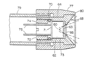
図2Aは、図1の放射線検出器のセンサアセンブリを示す。アセンブリは、米国特許出願第08/881,891号に示されたものに類似する。熱電対列(サーモパイル)60が缶62の中に公知の方法で取り付けられている。安定性を高めるために、熱電対列は、クセノンガスで囲まれた蒸着熱電対列を用いることも可能であるが、コストを引き下げるために空気雰囲気中の半導体熱電対列を使用することもできる。赤外線放射を透過させる窓63が缶の照準開口上に設けられている。缶62は、ヒートシンク64の孔の中に組み込まれている。孔の肩部分で缶を位置決めし、円錐カップ68の底部の開口66を通し熱電対列が測定対象に照準を合わせる。好ましくは、カップは低放射率を持ち、米国特許第4,636,091号に開示されている放射率を補償する。好ましくは、ヒートシンク64はアルミニウム製であり、その中にカップが形成されている。代わりに、ヒートシンク64は真鍮製でカップ領域にはニッケルメッキを施すことができる。
【0024】
弾性O−リング70が缶62の背後に置かれている。プラグ72をヒートシンク64の孔の中にねじ込み、リング70を缶のフランジ71の背面に押し付け、これによりフランジ71をヒートシンクの孔の肩部分に密着させる。フランジ71を肩に押し付け、孔の大径に対して許容差を小さく保つことにより、缶の側部と前部に空隙73が維持される。この構造により缶62の背面とヒートシンク64との間に良好な熱接触が生じ、また熱電対列が機械的衝撃に対する高い耐性を持つ。衝撃は衝撃吸収弾性体を通過して薄いフランジを通してのみ伝達されるからである。フランジが金属部品の間に強固に保持されていると、缶のガスシールを破壊する衝撃の危険性が生じることになる。開口74をプラグ72の中心を貫通して設け、ここを通り電気リード75が熱電対列缶に達する。ヒートシンク64は、検出器のチューブ状ヘッド79にねじ結合しているプラスチックキャップ77に圧入される。
【0025】
センサアセンブリがその中に取り付けられているプラスチックキャップ77は、低熱伝導性材料であり、熱伝導性は、好ましくはアルミニウムの1/100よりも小さい。ハウジングは、ヒートシンク64を周囲環境から熱的に絶縁することによりヒートシンクへの熱の流れを最小にする。またヒートシンク64の熱容量は大きい値を持つ。したがってハウジングが曝される環境温度の変化に伴なう、放射線センサの温度の変化に対するRC時定数を大きくして、温度の読取値をさらに安定化させることができる。熱抵抗は低熱伝導性ハウジングにより高くなり、また熱容量はヒートシンク64の大きい質量により大きくなる。RC時定数は、少なくとも5分であり、好ましくは約25分である。
【0026】
米国特許第4,993,419号に開示されているような赤外線温度計の過去の設計は、ヒートシンクの役割も兼ねている質量の大きい熱電対列缶を主体としていた。この設計によれば、ヒートシンクに伝達される熱に対する冷接点の温度応答の熱RC時定数に比して、ヒートシンクへの外部熱バリヤを通る熱伝達がさらに高いRC時定数を持つことが保証される。後者の低いRC時定数は、特別に設計された缶/ヒートシンクにおいて高価な高伝導率材料を用いることにより、冷接点に対する低い熱抵抗を保証することにより得られた。本発明の装置における設計目標は、公知の設計では低い熱抵抗を実現できない軽量の缶に従来の低コストの電対列を取り付けて使用することにある。したがって、熱電対列に伝導されるすべての熱が、熱電対列に対する熱的基準点(サーマルグラウンド)として機能する缶の後部を確実に通るように、缶が取り付けられることが重要である。この目的は、缶への熱接触を後部フランジを通して行い、また缶の側面および前面の周りに空隙を維持することにより果たされる。
【0027】
ヒートシンク内に放射率補償カップ68を形成することにより、組み立てのコストを引下げ、また熱特性を改良する。カップの放射率は、理想的にはゼロであるが実際には約0.1である。カップをヒートシンクの一部として形成することにより、カップの温度は缶の温度基準になる。したがって、表面68からの熱放射は冷接点とほぼ同じ温度で行なわれるため、外部からは認められない。また電子回路を調整して、放射率が理想的でないことに起因する反射率の損失を補償することができるが、この調整は反射表面の温度による影響を受ける。表面68の温度を熱電対列缶の基準温度を示すことを保証することにより、一般に表面温度が既知となり、温度依存性を持った補償を行うことが可能となる。
【0028】
家庭用として使用するときには、臨床用体温計による患者間での感染の恐れはそれほど大きくない。さらに額では、水分の蒸発は耳および腋窩の場合程に著しくはない。したがって米国特許出願第08/469,484号および第08/738,300号のような公知の赤外線体温計に用いられる使い捨ての放射線透過カバーは不要である。しかし臨床用の場合には、放射線透過カバーは感染を防止するために望ましい。
【0029】
額に沿って放射線検出器を走査する間、ハウジング78と皮膚との接触が皮膚を冷却させることになる。この冷却効果を最小にするために、円形のリップ80がヒートシンク64の先端を越えて軸方向に突き出ている。リップは、断熱材料を通る熱伝達を最小にするために0.02〜0.05インチ(0.5〜1.3mm)、好ましくは0.03インチ(0.8mm)の小さい丸みを持つ。ヒートシンク64は、リップの先端より0.02〜0.04インチ(0.5〜1.0mm)、好ましくは約.03インチ(0.8mm)だけ後退している。走査を容易にするためにリップは平滑な曲線を持つ。
【0030】
図2Bに、放射線センサアセンブリの別の実施形態を示す。前の実施形態と同様に、熱電対列120は缶122の中に位置する。缶は、ヒートシンク124内にO−リング126により保持され、O−リングは缶のフランジ128に押し付けられ、ヒートシンクの孔130の円周溝内に組み込まれる。前記と同様に、電気リード132が孔130を通って延びる。検出器ヘッドのハウジング134は、長手方向の継目に沿って合わさる2つの部分から形成される分割型チューブである。チューブの2つの部分はナット136により互いに結合され、このナットにプラスチックキャップ138をはめ込んでいる。ヒートシンクは、アセンブリ内にO−リング140により保持され、このO−リングはヒートシンクの中の溝およびナット136の溝内にはまり込んでいる。前記の場合と同様に、キャップ138は、ヒートシンク124の先端を越えて延びる曲線状のリップを持つ。キャップ138は、患者の快適性のために軟質材料を使用している。
【0031】
図2Cの実施形態においては、熱電対列は、米国特許第5,012,813号に開示されたものと類似の熱容量の大きい缶150内に位置する。缶はスリーブ152内に組み込まれ、スリーブはO−リング156および158によりヘッドハウジング154内に維持されている。プラスチックキャップ160は、ヘッド154にねじ込まれ、缶150は追加の0−リング162によりキャップの中心に固定される。低放射率のカップ164はキャップ160の中に圧入され、前記と同様に、平滑リップ116よりも後退している。
【0032】
図3に放射線検出器の電気ブロック図を示す。マイクロプロセッサ80が回路の要部をなす。電源制御回路82がユーザによるボタンスイッチ84の作動に応答して、マイクロプロセッサおよび回路の他の素子に電力を供給する。この電力は、マイクロプロセッサが測定サイクルを完了して、電源制御回路82に停止の信号を送るまで供給され続ける。マイクロプロセッサは発振器回路86によって計時され、通信線88を介して外部装置と通信してプログラミングおよび較正を行うことができる。マイクロプロセッサによって測定された温度は、液晶表示器100に表示され、温度処理中のピーク値の検出はビーパ(ビープ音の発生手段)102によって知らせられる。ピーク値は毎秒少なくとも3回、好ましくは毎秒10回の割合で得られた読取値から検出される、これは額に沿って迅速に走査することにより、検出器による額の冷却を防止するためである。測定処理中、マイクロプロセッサは、マルチプレクサ/アナログ−ディジタル変換器90によって読み取りを行う。好ましいマイクロプロセッサ80は、内部に8ビットA−D変換器を有するPIC16C74である。コストをできるだけ少なくするために、回路はこのA−D変換器だけに依存する設計である。
【0033】
熱電対列92は、基準電圧(Vref)94によってオフセットされた目標温度と熱電対列の冷接点の温度との4乗差に等しい電圧出力信号を供給する。熱電対列からの電圧出力は、1000程度のゲイン(G)を持つ増幅器96により増幅され、前記増幅器96はマイクロプロセッサにより制御されるパルス幅変調フィルタ108によって決められたオフセットを供給する。マルチプレクサの動作を通じて、マイクロプロセッサは増幅センサ出力および検出器温度センサ98により供給された検出器温度Tdのアナログ/ディジタル(A/D)変換を行う。検出器温度センサ98は、熱電対列の冷接点、缶およびヒートシンクのほぼ一定の温度を感知するように位置決めされる。先の米国特許出願第08/738,300号に記載されているように、オートゼロスイッチ104を備えて、較正シーケンス中に熱電対列92と増幅器96の分離を可能にしている。
【0034】
熱電対列の出力が(Ts 4−Td 4)に比例することは良く知られている。ここでTsは放射線検出器により観察される目標皮膚温度であり、Tdはセンサ98によって測定される検出器の温度である。この関係からTsを算出することができる。また、計算された皮膚温度と皮膚の曝されている環境温度とに基づいて、図4に示す動脈熱平衡方法を使用して体内コア温度を算出することができる。体内コア温度Tcからの熱流束qは、皮膚30を通って温度Taの周囲環境へ出る。これにより、皮膚は中間温度TSに保持される。
【0035】
額、外耳道または腋窩などの皮膚から周囲環境への放熱は、以下の周知の式で計算できる。
【0036】
【数2】
ここで、qは熱流、Aは表面積、TsおよびTaはそれぞれ皮膚温度および環境温度であり、hは皮膚組織と周囲との間の放射線観察ファクタを含む経験的に求められた係数である。式は簡単化のために線形としている。式の正確な形式は、放射線交換のために4次式であるが、線形化された式でも約90°〜105゜F(32〜41℃)の対象範囲では高い精度を有する。
【0038】
核心動脈熱源から皮膚への熱流は、血液循環を介して行われる。この血液循環は、組織伝達よりも何倍も効果的である。循環による熱伝達は、下記の式により表わすことができる。
【0039】
【数3】
この場合もqは熱流であり、Wは血液質量流量、Cは血液の比熱であり、またTcおよびTsはそれぞれコア温度および皮膚温度である。
【0041】
したがって、皮膚の温度は、式(3)による血液供給により組織が昇温し、式(2)による周囲環境への放熱により均合う結果である、と熱的に考えることができる。
【0042】
次の等式が成り立つ。
【0043】
【数4】
表面積Aで両辺を除すことにより簡単化される。
【0045】
【数5】
ここでpは単位面積当りの血液流量、潅流率とも呼ばれている。
【0047】
この時、皮膚温度Tsおよび環境温度Taが既知で、係数(またはその比)が経験的に求められているときには、式(5)はコア温度Tcを算出する方法を提供する。
【0048】
Tcについて解けば、
【0049】
【数6】
ここでh/pcは表面温度と環境温度との差に重み付けする重み係数で、患者および臨床状況の範囲で統計をとって経験的に求められる。
【0051】
算出の代替法は、電気的アナログ手法を用いるものである、何故ならば式(2)および(3)は共に簡単な電圧/電流関係の理想的な形を持つためである。この方法は、電流は熱の流れに類似し、電位差は温度差に類似するということを用いている。
【0052】
したがって式(2)および(3)は、次のように書くことができる。
【0053】
【数7】
【数8】
また電気回路は、TcとTaを一定温度(電圧)蓄積手段(reservoir)として描くことができる(図4)。さらに便利な形を持つ第3の式は、次のように書くことができる。
【0056】
【数9】
式(7)および(9)を用いてTcを解くと、
【0058】
【数10】
最後に次の式が得られる。
【0060】
【数11】
この式は、動脈熱平衡装置にプログラミングされた熱平衡式の正確な形で、(R1+R2)/R1は係数kとして表される。
【0062】
係数kは、次のように書くことができる。
【0063】
【数12】
したがって式(6)、および(11)のいずれの形においても、重み係数h/pcが表面温度と環境温度の差に適用されていることが分かる。
【0065】
重み係数において、cは一定である。耳温度および新生児の腋窩温度測定において潅流率は一般に一定であり、したがって成人の耳では約0.09、また新生児では0.05のh/pcになる。正常な成人では、腋窩の潅流率は、重み係数h/pcが約0.13となるような値である。さらに、潅流率は患者の状態によって変わる。特に、熱の出ているときには潅流率は極めて大きくなる。同様に額では、潅流率は皮膚温度によって変動する。
【0066】
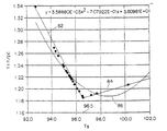
耳および腋窩の両方で、係数hは比較的一定である。額は周囲環境に曝される機会が多く、皮膚温度の上昇と共に放射熱損失も増大する。したがって、耳および腋窩温度測定では、全上昇皮膚温度に対して重み係数h/pcは低下し続けるが、額の場合、図5に示すように、重み係数は正常に近い体温で最小値に到達し、その後hの値の上昇により増加することが分かる。経験的なデータは、値h/pcは直線82で示すように、その値が約0.19および約96〜97゜F(35.6〜36.1℃)の温度にまで直線的に低下することを示している。次に係数は、皮膚温度と共に直線的に増加するが、直線84において勾配はゆるやかとなる。図5に図示された線形近似は、臨床モデルにおける算出に用いられる。しかし消費者モデルでは、これらの線形近似は単一多項式近似86により置き替えられる。
【0067】
【数13】
人体のすべての部位の関心のある温度は、動脈温度源から生じるため、動脈熱平衡はいかなる部位にも適用できる。したがってテブナン等価定理に基づき、動脈温度に対する耳および直腸の診断等価温度ToおよびTrは、抵抗RoおよびRrを経験的に考慮に入れて係数kを適切に選択して計算することができる。
【0069】
側頭動脈および他の動脈からの温度読取値を提供するのに特に適する放射線検出器の各構成は、出願人の先の設計から知ることができる。しかしこれらの設計の何れもが、皮膚表面に近い動脈に沿って走査することによりコア温度に整合した測定を可能にする素子の特有の組み合わせを提供することはない。特にExergen D501 Industrialの温度検出器を放射率補償カップに用い、ピーク温度を毎秒約10回の温度読取値に基づいて求めた。しかし、この装置は熱平衡算出を実行していないため、コア温度の測定には適さなかった。放射率補償カップを、熱平衡算出を持つ腋窩温度検出器に利用したが、このユニットは目標表面に沿って走査するには適さなかった。この装置で検出されたピーク値が、読取値が安定して信頼できた時を示すのに用いられた。このピーク値検出は、毎秒1回だけの読み取りに基づいた。出願人の先の耳温度検出器は、ピーク温度を毎秒10回の読み取り値から求めたが、目標表面に沿った走査によるのではなく検出器をピボット運動させたものであった。
【0070】
本発明を好ましい実施形態に基づいて図示し記述してきたが、当業者には形態および細部における各種の改変が、添付の特許請求の範囲により限定された本発明の範囲を逸脱することなく、実施可能なことは理解されるであろう。
【図面の簡単な説明】
【図1】 本発明による額の側頭動脈を走査する赤外線体温計を示す図である。
【図2A】 本発明による赤外線体温計の一実施形態にかかる放射線センサアセンブリの断面図である。
【図2B】 図2Aとは別の放射線センサアセンブリの断面図である。
【図2C】 図2Aおよび図2Bとは別の放射線センサアセンブリの断面図である。
【図3】 図1の体温計の電子回路にかかる回路ブロック線図である。
【図4】 動脈の熱平衡モデルを示す。
【図5】 皮膚温度の変化に伴う重み係数(1+h/pc)の変化を示す。
【符号の説明】
20…温度検出器(放射線センサ)、63…窓、66…開口、68…反射カップ、80…リップ。[0001]
BACKGROUND OF THE INVENTION
The present invention relates to a body temperature detection method and a body temperature detector that measure body temperature (core temperature) of newborns, children, and adults by detecting the temperature of the surface of human skin.
[0002]
[Background Art and Problems to be Solved by the Invention]
In recent years, infrared thermometers have been widely used to measure adult body temperature. An infrared thermometer inserted into the patient's ear is extremely effective for reading the core temperature (the temperature of the deep part of the body). Early infrared thermometers were inserted into the ear canal, observing the eardrum, and reading directly without correcting the eardrum temperature, which correlates with the pulmonary artery temperature. More recently, however, ear thermometers are designed to read the corrected temperature at the distal end of the ear canal, which is generally cooler, to make it more comfortable and easier to use. Such a thermometer measures the temperature of the distal ear canal tissue and calculates the arterial core temperature by thermal equilibrium.
[0003]
The term “core temperature” is used to express the temperature of the deep part of the body, and is approximated by the oral cavity, rectum, ear, pulmonary artery, esophagus and bladder temperature, and the like. Of these temperatures, the pulmonary artery temperature most accurately indicates the core temperature. This is because the pulmonary artery is closest to the heart and its blood is supplied to all tissues. The calculated value of arterial core temperature due to thermal equilibrium approximates the pulmonary artery temperature, and the core temperature refers to the pulmonary artery temperature unless otherwise specified.
[0004]
The arterial thermal balance measurement method is based on a model of heat flow through a series of thermal resistances from the arterial core temperature to the ear skin temperature and from the ear skin temperature to the ambient temperature. Therefore, the arterial core temperature can be calculated after detecting the skin temperature and the environmental temperature. The thermal resistance model allows calculation of values corresponding to oral and rectal temperatures by simply adjusting the weighting factor in the calculation. Infrared ear thermometers using arterial thermal balance are disclosed in US Pat. Nos. 4,993,419, 5,012,813, 5,199,436, 5,381,796, 5,445, 158, 5,653,238 and 5,271,407, the entire texts of which are hereby incorporated by reference as part of this specification.
[0005]
In particular for neonates, an axillary (under the arm) infrared thermometer was introduced to overcome clinical difficulties in using ear thermometers. Infrared thermometers for measuring axillary temperature are described in US patent application Ser. Nos. 08 / 469,484, 08 / 738,300 and 08 / 881,891, the entire text of which is incorporated herein by reference. It is quoted here as part of it. In each of these devices, the detector head of the infrared detector protrudes from the temperature indicating housing and is simply slid into the axilla to lightly touch the top of the axilla, and accurate infrared in just a half second A temperature reading can be obtained. Axillary thermometers are also based on arterial thermal balance measurement methods and allow arterial, oral, or rectal temperature measurements.
[0006]
Axillary infrared thermometers have been used not only for newborns but also for mass screening of the general public and especially children, whose body temperature is difficult to measure with sublingual or rectal thermometers.
[0007]
In ear and neonatal axillary temperature measurements, the difference between skin temperature and ambient temperature is weighted by a factor that also approximates h / pc. Here, h is an empirically determined coefficient including a radiation observation factor between the skin tissue and the surroundings, p is a perfusion rate, and c is a specific heat of blood. For ear and neonatal axillary temperature measurements, this factor is empirically known to be about 0.09 and 0.05, respectively, with little variation. However, in the case of large heat transfer and high vasomotor function, the coefficient is empirically about. 13 and varies more greatly depending on the body temperature of the patient.
[0008]
[Means for Solving the Problems]
The present invention makes temperature measurements in neonates, children and adults particularly easy by detecting the temperature of the forehead located just above the temporal artery near the epidermis.
[0009]
Arteries are suitable for detecting core temperature because arteries directly flow from the heart, but arteries in the extremities of the body, for example, arteries in the wrist or ankle where they are pulsed, are subject to significant vasoconstriction. . This is because, for example, if the person is in a severe state of shock, or has a mild cold or nervousness, the arteries will contract and restrict blood flow to the site to conserve heat or shock. It means trying to send more blood to the dangerous area, as if received. This results in large temperature changes in arteries that are only local artifacts and do not indicate core temperature.
[0010]
With the exception of these limb arteries, in an attempt to reproduce the temperature of the blood source (heart), it is as close to the heart as possible, has a high blood flow and is relatively constant, and is easily accessible to all people. The present inventors have found a temporal artery as being able to do this. The heart, lungs and brain are essential to our presence, and the blood supply to these organs is continuous at the highest possible level, even when other parts become inadequate in a serious disease situation Maintained.
[0011]
The artery that originates in the heart is the aorta, the main trunk of the arterial system. The direct extension of the aorta is the common carotid artery, where a solid artery extends into the upper neck and branches into an internal carotid artery and an external carotid artery. The carotid artery, even the external carotid artery, is partly buried in the skull, even in the best case, and in the worst case completely buried in the skull, and therefore cannot be accessed through the skin. Extending directly from the carotid artery is the temporal artery, which again branches into two medial and lateral temporal arteries. The present inventors have found that the lateral temporal artery extends in front of the ear, extends into the soft temporal region, and branches off between the skin close to the eyebrows and the skull.
[0012]
It is clear that the temporal artery is very easy to approach and in fact, in most people, it is usually visible with the eye. Since it ends in a bifurcated form, the reliability of measuring the correct position is easily doubled. Touching the temporal artery does not create a risk of injury. Since there is no mucous membrane, there is no fear of contamination seen in the oral cavity and rectum. Despite being near the skin surface, temporal artery perfusion, which is blood flow per unit volume of tissue, is relatively constant, thus ensuring the stability of the blood flow required for measurement.
[0013]
According to one configuration of the present invention, a temperature sensor is scanned along the forehead, preferably in the vicinity of the temporal artery, to obtain a temperature peak reading. During the scan, at least 3 readings are performed per second, preferably 10 or more times per second. This method can also be applied to other arteries close to the skin, such as an axilla. preferabletemperatureThe sensor is a radiation sensor aiming at a forehead measurement object through a reflective cup. The cup has a large opening diameter that approaches the object to be measured and a window at the bottom of the cup, through which the radiation sensor is aimed at the object to be measured. The cup is also outside the field of view of the sensor. The reflective cup is spaced from the object to be measured by a smooth lip of material with low thermal conductivity.
[0014]
Like a known ear and axillary thermometer, the core temperature in the body can be calculated from the following equation.
[0015]
[Expression 1]
Where TsAnd TaAre skin temperature and ambient temperature, respectively. It can be seen that the above equation has a weight coefficient h / pc and includes a weighted difference between the surface temperature and the environmental temperature.
[0017]
According to another configuration of the present invention, the detector electronics calculates the internal body temperature as a function of the ambient temperature and the sensed surface temperature. The function includes a weighted difference between the surface temperature and the environmental temperature, and the weight varies depending on the temperature of the measurement target. In particular, the weighting is an approximation of h / pc in the forehead artery, h is the heat transfer coefficient between the measurement object and the surroundings, p is the perfusion rate, and c is the specific heat of the blood.
[0018]
Thermal equilibrium calculations are most accurate when peak temperatures are detected. That is, h / pc is the minimum when the perfusion rate p is a peak value, and the heat transfer coefficient h is substantially constant. Thus, the detector can discriminate the peak temperature at one of the temporal artery branches.
[0019]
DETAILED DESCRIPTION OF THE INVENTION
The above and other objects, features and advantages of the present invention will become apparent from the description of preferred embodiments of the present invention with reference to the drawings. Throughout the drawings, the same reference numerals are used for the same parts. The drawings are not necessarily to scale, emphasis being placed on illustrating the principles of the invention.
[0020]
As shown in FIG. 1, the
[0021]
Temperature to position the temporal arteryDetector 20Preferably, the
[0022]
The
[0023]
FIG. 2A shows a sensor assembly of the radiation detector of FIG. The assembly is similar to that shown in US patent application Ser. No. 08 / 881,891. A thermopile 60 is mounted in the
[0024]
A resilient O-
[0025]
The
[0026]
Past designs of infrared thermometers as disclosed in U.S. Pat. No. 4,993,419 have been based on high mass thermocouple cans that also serve as heat sinks. This design ensures that the heat transfer through the external thermal barrier to the heat sink has a higher RC time constant compared to the thermal RC time constant of the cold junction temperature response to the heat transferred to the heat sink. The The latter low RC time constant was obtained by ensuring a low thermal resistance to the cold junction by using expensive high conductivity materials in specially designed can / heat sinks. The design goal of the device of the present invention is to use a conventional low cost couple of strings coupled to a lightweight can that cannot achieve low thermal resistance with known designs. Therefore, it is important that the can be mounted to ensure that all heat conducted to the thermocouple string passes through the rear of the can, which serves as a thermal reference point for the thermocouple string. This objective is accomplished by making thermal contact to the can through the rear flange and maintaining a gap around the side and front of the can.
[0027]
Forming the
[0028]
When used for home use, the risk of infection among patients with a clinical thermometer is not so great. Furthermore, at the forehead, the evaporation of moisture is not as pronounced as in the ear and axilla. Accordingly, disposable radiation transmissive covers used in known infrared thermometers such as US patent application Ser. Nos. 08 / 469,484 and 08 / 738,300 are not required. However, for clinical use, a radiolucent cover is desirable to prevent infection.
[0029]
While scanning the radiation detector along the forehead, the contact between the housing 78 and the skin will cause the skin to cool. In order to minimize this cooling effect, a
[0030]
FIG. 2B illustrates another embodiment of a radiation sensor assembly. Similar to the previous embodiment, the thermocouple array 120 is located in the
[0031]
In the embodiment of FIG. 2C, the thermocouple train is located in a high heat capacity can 150 similar to that disclosed in US Pat. No. 5,012,813. The can is incorporated in a
[0032]
FIG. 3 shows an electrical block diagram of the radiation detector. A
[0033]
The
[0034]
The output of the thermocouple string is (Ts Four-Td FourIt is well known that it is proportional to Where TsIs the target skin temperature observed by the radiation detector and TdIs the temperature of the detector measured by the
[0035]
The heat release from the skin, such as the forehead, ear canal or axilla, to the surrounding environment can be calculated by the following well known formula
[0036]
[Expression 2]
Where q is the heat flow, A is the surface area, TsAnd TaAre skin temperature and ambient temperature, respectively, and h is an empirically determined coefficient including a radiation observation factor between the skin tissue and the surroundings. The formula is linear for simplicity. The exact form of the equation is quartic for radiation exchange, but the linearized equation also has high accuracy in the target range of about 90 ° to 105 ° F. (32 to 41 ° C.).
[0038]
Heat flow from the nuclear heart artery heat source to the skin occurs through blood circulation. This blood circulation is many times more effective than tissue transmission. Heat transfer by circulation can be expressed by the following equation.
[0039]
[Equation 3]
Again, q is the heat flow, W is the blood mass flow rate, C is the specific heat of the blood, and TcAnd TsAre core temperature and skin temperature, respectively.
[0041]
Therefore, the temperature of the skin can be considered thermally as a result of the temperature rising of the tissue due to the blood supply according to Equation (3) and the balance due to the heat radiation to the surrounding environment according to Equation (2).
[0042]
The following equation holds:
[0043]
[Expression 4]
Simplified by dividing both sides by surface area A.
[0045]
[Equation 5]
Here, p is also called a blood flow rate per unit area and a perfusion rate.
[0047]
At this time, skin temperature TsAnd ambient temperature TaIs known and the coefficient (or its ratio) has been determined empirically, equation (5) can becA method for calculating the value is provided.
[0048]
TcIf you solve about
[0049]
[Formula 6]
Here, h / pc is a weighting factor for weighting the difference between the surface temperature and the environmental temperature, and is obtained empirically by taking statistics in the range of patients and clinical situations.
[0051]
An alternative method of calculation is to use an electrical analog approach, because both equations (2) and (3) have an ideal form of a simple voltage / current relationship. This method uses that current is similar to heat flow and potential difference is similar to temperature difference.
[0052]
Thus, equations (2) and (3) can be written as:
[0053]
[Expression 7]
[Equation 8]
The electrical circuit is TcAnd TaCan be drawn as a constant temperature (voltage) storage means (reservoir) (FIG. 4). A third expression with a more convenient form can be written as:
[0056]
[Equation 9]
Using equations (7) and (9), TcAnd solving
[0058]
[Expression 10]
Finally, the following equation is obtained.
[0060]
## EQU11 ##
This equation is an exact form of the thermal balance programmed into the arterial thermal balance device, (R1+ R2) / R1Is expressed as a coefficient k.
[0062]
The coefficient k can be written as:
[0063]
[Expression 12]
Therefore, it can be seen that the weight coefficient h / pc is applied to the difference between the surface temperature and the environmental temperature in both forms of the equations (6) and (11).
[0065]
In the weighting factor, c is constant. In ear temperature and neonatal axillary temperature measurements, the perfusion rate is generally constant, thus approximately 0.09 for adult ears and 0.05 h / pc for neonates. In normal adults, the axillary perfusion rate is such that the weighting factor h / pc is about 0.13. Furthermore, the perfusion rate varies with the patient's condition. In particular, the perfusion rate is extremely high when heat is generated. Similarly, at the forehead, the perfusion rate varies with skin temperature.
[0066]
In both the ear and the axilla, the coefficient h is relatively constant. The forehead is often exposed to the surrounding environment, and radiant heat loss increases with increasing skin temperature. Therefore, in the ear and axillary temperature measurement, the weighting factor h / pc continues to decrease with respect to the total elevated skin temperature. Then, it can be seen that it increases as the value of h increases. Empirical data shows that the value h / pc falls linearly to a temperature of about 0.19 and about 96-97 ° F. (35.6-36.1 ° C.) as shown by
[0067]
[Formula 13]
Since the temperature of interest in all parts of the human body originates from the arterial temperature source, arterial thermal balance can be applied to any part. Therefore, based on the Thevenin equivalence theorem, the ear and rectal diagnostic equivalent temperature T to the arterial temperature.oAnd TrIs the resistance RoAnd RrCan be calculated by appropriately selecting the coefficient k.
[0069]
Each configuration of a radiation detector that is particularly suitable for providing temperature readings from the temporal artery and other arteries can be known from Applicants' previous designs. However, none of these designs provide a unique combination of elements that allows measurements to be matched to the core temperature by scanning along an artery close to the skin surface. In particular, a temperature detector from Exergen D501 Industrial was used for the emissivity compensation cup and the peak temperature was determined based on temperature readings of about 10 times per second. However, this apparatus is not suitable for measuring the core temperature because it does not perform thermal equilibrium calculation. An emissivity compensation cup was used for an axillary temperature detector with thermal balance calculations, but this unit was not suitable for scanning along the target surface. The peak value detected with this device was used to indicate when the reading was stable and reliable. This peak value detection was based on a single reading per second. Applicant's earlier ear temperature detector determined the peak temperature from 10 readings per second, but pivoted the detector rather than by scanning along the target surface.
[0070]
While the invention has been illustrated and described in terms of preferred embodiments, those skilled in the art will recognize that various modifications in form and detail may be made without departing from the scope of the invention as defined by the appended claims. It will be understood that it is possible.
[Brief description of the drawings]
FIG. 1 shows an infrared thermometer for scanning the temporal artery of the forehead according to the present invention.
FIG. 2A is a cross-sectional view of a radiation sensor assembly according to an embodiment of an infrared thermometer according to the present invention.
FIG. 2B is a cross-sectional view of another radiation sensor assembly different from FIG. 2A.
FIG. 2C is a cross-sectional view of another radiation sensor assembly different from FIGS. 2A and 2B.
FIG. 3 is a circuit block diagram according to the electronic circuit of the thermometer of FIG. 1;
FIG. 4 shows an arterial thermal equilibrium model.
FIG. 5 shows a change in weighting factor (1 + h / pc) accompanying a change in skin temperature.
[Explanation of symbols]
20 ... Temperature detector (radiation sensor), 63 ... Window, 66 ... Opening, 68 ... Reflecting cup, 80 ... Lip.
Claims (9)
ピーク温度を測定する電子回路(80)とを備えた走査型体温検出器において、
当該温度検出器が動脈に沿って走査される間における毎秒少なくとも3回の読み取りからピーク温度が測定され、動脈から環境への熱流のモデルに基づき温度表示を提供するように、検出されたピーク温度が前記電子回路において処理されることを特徴とする走査型体温検出器。A temperature sensor ( 60, 92);
A scanning body temperature detector comprising an electronic circuit (80) for measuring the peak temperature;
The detected peak temperature so that the peak temperature is measured from at least three readings per second while the temperature detector is scanned along the artery and provides a temperature indication based on a model of heat flow from the artery to the environment. Is processed in the electronic circuit .
前記放射線センサ(60)が測定対象に照準を合わせる際に介する反射カップ(68,164)であって、測定対象に接近する大きな開口径と底部の窓とを有し、前記窓を通して前記放射線センサ(60)が測定対象に照準を合わせ、前記放射線センサ(60)の視野外に存在する反射カップ(68,164)と、
キャップ(77,160)であって、この内側に前記反射カップ(68,164)が接触しているキャップ(77,160)と、
当該体温検出器が測定対象に沿って走査される間における毎秒少なくとも3回の読み取りからピーク温度を測定する電子回路であって、検出されたピーク温度を処理することにより人体から環境への熱流のモデルに基づき温度表示を提供する電子回路とを備えた走査型体温検出器。A radiation sensor (60) for aiming at the region to be measured;
The radiation sensor (60) is a reflection cup (68, 164) through which the object to be measured is aimed, and has a large opening diameter approaching the object to be measured and a bottom window, and the radiation sensor passes through the window. (60) aiming at the object to be measured, and a reflection cup (68, 164) existing outside the field of view of the radiation sensor (60) ;
A cap (77, 160) having the reflective cup (68, 164) in contact with the cap (77, 160);
An electronic circuit that measures the peak temperature from at least three readings per second while the body temperature detector is scanned along the object to be measured, and processes the detected peak temperature to reduce heat flow from the human body to the environment. A scanning body temperature detector with an electronic circuit that provides a temperature indication based on the model.
Applications Claiming Priority (3)
| Application Number | Priority Date | Filing Date | Title |
|---|---|---|---|
| US09/151,482 US6292685B1 (en) | 1998-09-11 | 1998-09-11 | Temporal artery temperature detector |
| US09/151,482 | 1998-09-11 | ||
| PCT/US1999/020855 WO2000016051A1 (en) | 1998-09-11 | 1999-09-10 | Temporal artery temperature detector |
Publications (3)
| Publication Number | Publication Date |
|---|---|
| JP2002525132A JP2002525132A (en) | 2002-08-13 |
| JP2002525132A5 JP2002525132A5 (en) | 2006-11-09 |
| JP4481496B2 true JP4481496B2 (en) | 2010-06-16 |
Family
ID=22538964
Family Applications (1)
| Application Number | Title | Priority Date | Filing Date |
|---|---|---|---|
| JP2000570539A Expired - Fee Related JP4481496B2 (en) | 1998-09-11 | 1999-09-10 | Temporal artery temperature detector |
Country Status (6)
| Country | Link |
|---|---|
| US (6) | US6292685B1 (en) |
| EP (2) | EP1114302B1 (en) |
| JP (1) | JP4481496B2 (en) |
| AT (1) | ATE544058T1 (en) |
| AU (1) | AU5821299A (en) |
| WO (1) | WO2000016051A1 (en) |
Cited By (1)
| Publication number | Priority date | Publication date | Assignee | Title |
|---|---|---|---|---|
| JP2019012027A (en) * | 2017-06-30 | 2019-01-24 | 株式会社テクノ・コモンズ | Biological data measuring device |
Families Citing this family (163)
| Publication number | Priority date | Publication date | Assignee | Title |
|---|---|---|---|---|
| US6056435A (en) * | 1997-06-24 | 2000-05-02 | Exergen Corporation | Ambient and perfusion normalized temperature detector |
| US6292685B1 (en) * | 1998-09-11 | 2001-09-18 | Exergen Corporation | Temporal artery temperature detector |
| IL126224A0 (en) | 1998-09-15 | 1999-05-09 | Gerlitz Jonathan | Ear thermometer and detector therefor |
| WO2000035339A1 (en) * | 1998-12-15 | 2000-06-22 | Citizen Watch Co., Ltd. | Radiation clinical thermometer |
| JP2003503693A (en) * | 1999-06-23 | 2003-01-28 | エリアフ ルビンスタイン、 | Heat alarm system |
| DE19929503B4 (en) * | 1999-06-28 | 2008-06-26 | Braun Gmbh | IR thermometers for different measuring locations |
| US6319206B1 (en) * | 1999-11-24 | 2001-11-20 | Exergen Corporation | Temporal thermometer disposable cap |
| IT1317648B1 (en) * | 2000-05-19 | 2003-07-15 | Tecnica S R L | PERFECTED INFRARED THERMOMETER |
| JP3690387B2 (en) * | 2000-06-13 | 2005-08-31 | オムロンヘルスケア株式会社 | Radiation thermometer |
| US6773405B2 (en) * | 2000-09-15 | 2004-08-10 | Jacob Fraden | Ear temperature monitor and method of temperature measurement |
| US20020132360A1 (en) | 2000-11-17 | 2002-09-19 | Flir Systems Boston, Inc. | Apparatus and methods for infrared calorimetric measurements |
| US6821787B2 (en) | 2000-11-17 | 2004-11-23 | Thermogenic Imaging, Inc. | Apparatus and methods for infrared calorimetric measurements |
| EP1249691A1 (en) * | 2001-04-11 | 2002-10-16 | Omron Corporation | Electronic clinical thermometer |
| JP3900865B2 (en) * | 2001-06-04 | 2007-04-04 | オムロンヘルスケア株式会社 | Infrared thermometer, infrared thermometer temperature state estimation method, information notification method, and measurement operation management method |
| US7017433B2 (en) * | 2001-10-04 | 2006-03-28 | Ssi Technologies, Inc. | Non-contacting sensor multichip module with integral heat-sinks |
| US10123732B2 (en) | 2002-04-22 | 2018-11-13 | Geelux Holdings, Ltd. | Apparatus and method for measuring biologic parameters |
| US8328420B2 (en) | 2003-04-22 | 2012-12-11 | Marcio Marc Abreu | Apparatus and method for measuring biologic parameters |
| US8849379B2 (en) * | 2002-04-22 | 2014-09-30 | Geelux Holdings, Ltd. | Apparatus and method for measuring biologic parameters |
| JP4347216B2 (en) * | 2002-04-22 | 2009-10-21 | マルシオ マルク アブリュー | Biological parameter measuring device |
| US6971790B2 (en) * | 2002-10-11 | 2005-12-06 | Welch Allyn, Inc. | Thermometry probe calibration method |
| US20040095985A1 (en) * | 2002-11-15 | 2004-05-20 | Ko Kun Yuan | Dual-use infrared thermometer |
| AU2007200873B2 (en) * | 2002-12-12 | 2008-04-03 | Cardinal Health 529, Llc | Thermal tympanic thermometer tip |
| PT1570246E (en) * | 2002-12-12 | 2009-04-09 | Covidien Ag | Thermal tympanic thermometer tip |
| US7434991B2 (en) * | 2002-12-12 | 2008-10-14 | Covidien Ag | Thermal tympanic thermometer |
| WO2004074794A1 (en) * | 2003-02-20 | 2004-09-02 | Ysi Incorporated | Digitally modified resistive output for a temperature sensor |
| CN1780581A (en) * | 2003-02-26 | 2006-05-31 | 马尔西奥·马克·奥雷利奥·马丁斯·阿布雷乌 | Apparatus and method for measuring biologic parameters |
| AU2014215951B2 (en) * | 2003-02-26 | 2015-11-19 | Abreu, Marcio Marc Aurelio Martins MR | Apparatus and method for measuring biologic parameters |
| AU2012247045B2 (en) * | 2003-02-26 | 2014-05-22 | Marcio Marc Aurelio Martins Abreu | Apparatus and method for measuring biologic parameters |
| CN105919562A (en) * | 2003-02-26 | 2016-09-07 | 马尔西奥·马克·奥雷利奥·马丁斯·阿布雷乌 | Appartus and method for measuring biologic parameters |
| US7500746B1 (en) | 2004-04-15 | 2009-03-10 | Ip Venture, Inc. | Eyewear with radiation detection system |
| US8109629B2 (en) | 2003-10-09 | 2012-02-07 | Ipventure, Inc. | Eyewear supporting electrical components and apparatus therefor |
| US7255437B2 (en) * | 2003-10-09 | 2007-08-14 | Howell Thomas A | Eyeglasses with activity monitoring |
| US8465151B2 (en) | 2003-04-15 | 2013-06-18 | Ipventure, Inc. | Eyewear with multi-part temple for supporting one or more electrical components |
| US7806525B2 (en) | 2003-10-09 | 2010-10-05 | Ipventure, Inc. | Eyeglasses having a camera |
| US7922321B2 (en) | 2003-10-09 | 2011-04-12 | Ipventure, Inc. | Eyewear supporting after-market electrical components |
| WO2004110248A2 (en) * | 2003-05-27 | 2004-12-23 | Cardiowave, Inc. | Remote technique to detect core body temperature in a subject using thermal imaging |
| US7785266B2 (en) | 2003-08-19 | 2010-08-31 | Advanced Monitors Corporation | Medical thermometer for determining body core temperature |
| US7938783B2 (en) * | 2003-08-19 | 2011-05-10 | Advanced Monitors Corporation | Medical body core thermometer |
| US20130281897A1 (en) * | 2003-09-04 | 2013-10-24 | Ahof Biophysical Systems Inc. | Non-invasive reperfusion system by deformation of remote, superficial arteries at a frequency much greater than the pulse rate |
| US10310296B2 (en) | 2003-10-09 | 2019-06-04 | Ingeniospec, Llc | Eyewear with printed circuit board |
| US11630331B2 (en) | 2003-10-09 | 2023-04-18 | Ingeniospec, Llc | Eyewear with touch-sensitive input surface |
| US7438410B1 (en) | 2003-10-09 | 2008-10-21 | Ip Venture, Inc. | Tethered electrical components for eyeglasses |
| US10345625B2 (en) | 2003-10-09 | 2019-07-09 | Ingeniospec, Llc | Eyewear with touch-sensitive input surface |
| US11513371B2 (en) | 2003-10-09 | 2022-11-29 | Ingeniospec, Llc | Eyewear with printed circuit board supporting messages |
| EP1530034A1 (en) * | 2003-11-05 | 2005-05-11 | Microlife Intellectual Property GmbH | An infrared thermometer and a method for determining a temperature |
| TWM251738U (en) * | 2004-01-30 | 2004-12-01 | Yuan Ho Harmony Co Ltd | Infrared temperature sensor |
| US10227063B2 (en) | 2004-02-26 | 2019-03-12 | Geelux Holdings, Ltd. | Method and apparatus for biological evaluation |
| EP1568975A1 (en) * | 2004-02-26 | 2005-08-31 | Microlife Intellectual Property GmbH | A probe assembly for an infrared medical thermometer and an infrared medical thermometer |
| US7479116B2 (en) * | 2004-05-20 | 2009-01-20 | Medism Ltd. | Temperature measurement device |
| DE102004028359B4 (en) * | 2004-06-11 | 2007-09-13 | Drägerwerk AG | Device for measuring body core temperature |
| US8337013B2 (en) | 2004-07-28 | 2012-12-25 | Ipventure, Inc. | Eyeglasses with RFID tags or with a strap |
| US11644693B2 (en) | 2004-07-28 | 2023-05-09 | Ingeniospec, Llc | Wearable audio system supporting enhanced hearing support |
| US11829518B1 (en) | 2004-07-28 | 2023-11-28 | Ingeniospec, Llc | Head-worn device with connection region |
| US11852901B2 (en) | 2004-10-12 | 2023-12-26 | Ingeniospec, Llc | Wireless headset supporting messages and hearing enhancement |
| WO2006044700A2 (en) * | 2004-10-13 | 2006-04-27 | Ysi Incorporated | Wireless patch temperature sensor system |
| US7083330B1 (en) * | 2004-10-19 | 2006-08-01 | Huang Hua Co., Ltd. | Ear thermometer having breakable ear cap |
| US7815367B2 (en) * | 2004-11-16 | 2010-10-19 | Welch Allyn, Inc. | Multi-site infrared thermometer |
| US7857507B2 (en) * | 2004-11-16 | 2010-12-28 | Welch Allyn, Inc. | Temperature patch and method of using the same |
| ITMI20050772A1 (en) * | 2005-04-29 | 2006-10-30 | Tecnimed Srl | EQUIPMENT FOR TEMPERATURE MEASUREMENT IN PARTICULAR OF A PATIENT |
| DE102005037921B3 (en) * | 2005-08-11 | 2006-06-14 | Dräger Medical AG & Co. KG | Temperature measuring device, for patient use, has evaluating means for detecting skin surface temperature from first temperature measured value and determines temperature at skin surface where double temperature sensor is in contact |
| US11733549B2 (en) | 2005-10-11 | 2023-08-22 | Ingeniospec, Llc | Eyewear having removable temples that support electrical components |
| SG180045A1 (en) | 2005-10-24 | 2012-05-30 | Marcio Marc Abreu | Apparatus and method for measuring biologic parameters |
| US7275867B2 (en) * | 2005-12-01 | 2007-10-02 | Oriental System Technology Inc. | Probe assembly of infrared thermometer |
| CA2538940A1 (en) * | 2006-03-03 | 2006-06-22 | James W. Haslett | Bandage with sensors |
| TWI274857B (en) * | 2006-03-03 | 2007-03-01 | Radiant Innovation | Structural improvement of a probe |
| US7597668B2 (en) * | 2006-05-31 | 2009-10-06 | Medisim Ltd. | Non-invasive temperature measurement |
| US7988352B2 (en) * | 2006-11-01 | 2011-08-02 | Radiant Innovation Inc. | Probe structure |
| EP2120681B1 (en) | 2007-03-15 | 2011-07-13 | Koninklijke Philips Electronics N.V. | Methods and devices for measuring core body temperature |
| US8308353B2 (en) * | 2007-03-26 | 2012-11-13 | Terumo Kabushiki Kaisha | Ear thermometer and method of manufacturing ear thermometer |
| US20080239920A1 (en) * | 2007-03-27 | 2008-10-02 | Francesco Pompei | Wireless transmission of temperature data |
| US8160836B2 (en) | 2007-04-17 | 2012-04-17 | Exergen Corporation | Wireless transmission of temperature data for a geographic area |
| US8167813B2 (en) * | 2007-05-17 | 2012-05-01 | Immersion Medical, Inc. | Systems and methods for locating a blood vessel |
| US20130096437A1 (en) * | 2007-08-21 | 2013-04-18 | Radiant Innovation Inc. | Method for detecting temple hot spot temperature of a live body |
| TW200909790A (en) * | 2007-08-21 | 2009-03-01 | Radiant Innovation Inc | Method of detecting living-body body temperature |
| US20090287120A1 (en) | 2007-12-18 | 2009-11-19 | Searete Llc, A Limited Liability Corporation Of The State Of Delaware | Circulatory monitoring systems and methods |
| US9717896B2 (en) | 2007-12-18 | 2017-08-01 | Gearbox, Llc | Treatment indications informed by a priori implant information |
| US8636670B2 (en) | 2008-05-13 | 2014-01-28 | The Invention Science Fund I, Llc | Circulatory monitoring systems and methods |
| US9672471B2 (en) | 2007-12-18 | 2017-06-06 | Gearbox Llc | Systems, devices, and methods for detecting occlusions in a biological subject including spectral learning |
| US20100036269A1 (en) * | 2008-08-07 | 2010-02-11 | Searete Llc, A Limited Liability Corporation Of The State Of Delaware | Circulatory monitoring systems and methods |
| US20090204008A1 (en) * | 2008-02-08 | 2009-08-13 | Daniel Beilin | Whole body infrared thermography systems and methods |
| US8185341B2 (en) * | 2008-05-30 | 2012-05-22 | Medisim Ltd. | Surface temperature profile |
| US7942825B2 (en) * | 2008-06-09 | 2011-05-17 | Kimberly-Clark Worldwide Inc. | Method and device for monitoring thermal stress |
| JP5308844B2 (en) * | 2009-01-28 | 2013-10-09 | 株式会社ミクニ | Infrared temperature measuring device |
| EP2419006B1 (en) | 2009-04-15 | 2015-09-30 | 3M Innovative Properties Company | Deep tissue temperature probe constructions |
| US9068895B2 (en) * | 2009-04-15 | 2015-06-30 | 3M Innovative Properties Company | Deep tissue temperature probe constructions |
| EP2278289A1 (en) | 2009-07-22 | 2011-01-26 | Medisim Ltd. | Thermometric apparatus and a method for thermometric measurement |
| US8226294B2 (en) * | 2009-08-31 | 2012-07-24 | Arizant Healthcare Inc. | Flexible deep tissue temperature measurement devices |
| US8226573B2 (en) * | 2009-11-16 | 2012-07-24 | Tyco Healthcare Group Lp | Thermometer probe |
| US8325048B2 (en) * | 2009-12-08 | 2012-12-04 | Kimberly-Clark Worldwide, Inc. | Thermal stress indicator |
| US20110194585A1 (en) * | 2010-02-09 | 2011-08-11 | Abhishek Shrivastava | Multiple object non-contact thermometer |
| US8301408B2 (en) * | 2010-03-09 | 2012-10-30 | Invensys Systems, Inc. | Temperature prediction transmitter |
| US8292495B2 (en) | 2010-04-07 | 2012-10-23 | Arizant Healthcare Inc. | Zero-heat-flux, deep tissue temperature measurement devices with thermal sensor calibration |
| US8292502B2 (en) | 2010-04-07 | 2012-10-23 | Arizant Healthcare Inc. | Constructions for zero-heat-flux, deep tissue temperature measurement devices |
| WO2011150404A2 (en) | 2010-05-27 | 2011-12-01 | Exergen Corporation | Method and apparatus for accurate detection of fever |
| TW201210569A (en) * | 2010-09-07 | 2012-03-16 | Radiant Innovation Inc | Infrared body temperature measuring device having communication function |
| US8714816B2 (en) | 2010-09-12 | 2014-05-06 | Medisim Ltd. | Temperature sensor with calibrated analog resistive output |
| US20120083710A1 (en) | 2010-09-30 | 2012-04-05 | Medism Ltd. | Ergonomic hand-held thermometer |
| WO2012067282A1 (en) | 2010-11-17 | 2012-05-24 | (주)이지템 | Mobile device and method for measuring temperature of thermal picture including body temperature |
| US8657758B2 (en) | 2010-12-02 | 2014-02-25 | Welch Allyn, Inc. | Devices and methods for temperature determination |
| US9354122B2 (en) | 2011-05-10 | 2016-05-31 | 3M Innovative Properties Company | Zero-heat-flux, deep tissue temperature measurement system |
| US8593251B2 (en) | 2011-06-16 | 2013-11-26 | Alan Camerik Heller | Systems for detecting a febrile condition and reducing risks of spreading infection |
| US9405135B2 (en) | 2011-09-15 | 2016-08-02 | Ipventure, Inc. | Shutter eyewear |
| US10624790B2 (en) | 2011-09-15 | 2020-04-21 | Ipventure, Inc. | Electronic eyewear therapy |
| US20130116591A1 (en) * | 2011-11-04 | 2013-05-09 | Alan C. Heller | Systems and devices for real time health status credentialing |
| US9320642B1 (en) * | 2012-06-04 | 2016-04-26 | The Surgical Company International B.V. | Method of and system for selecting patient temperature regulation tools |
| US8452382B1 (en) * | 2012-09-21 | 2013-05-28 | Brooklands Inc. | Non-contact thermometer sensing a carotid artery |
| WO2014070045A1 (en) * | 2012-10-30 | 2014-05-08 | Zakrytoe Aktsionernoe Obshchestvo "Cem Tehnolodzhi" | The method and the device for monitoring of diseases |
| US10042186B2 (en) | 2013-03-15 | 2018-08-07 | Ipventure, Inc. | Electronic eyewear and display |
| US20150057561A1 (en) * | 2013-08-26 | 2015-02-26 | Benny Tal | System, method and computer readable medium for determining a core temperature of a person |
| AU2014331655A1 (en) | 2013-10-11 | 2016-05-26 | Marcio Marc Abreu | Method and apparatus for biological evaluation |
| US9939334B2 (en) | 2013-12-05 | 2018-04-10 | Medisim, Ltd. | Fast responsive personalized thermometer |
| US9572647B2 (en) | 2013-12-31 | 2017-02-21 | i4c Innovations Inc. | Paired thermometer temperature determination |
| AU2015204638A1 (en) * | 2014-01-10 | 2016-07-21 | Marcio Marc Abreu | Device for measuring the infrared output of the Abreu brain thermal tunnel |
| JP2017505657A (en) | 2014-01-10 | 2017-02-23 | マーシオ マーク アブリュー | Device for monitoring and providing treatment in the Abreu brain tunnel |
| WO2015112776A2 (en) | 2014-01-22 | 2015-07-30 | Marcio Marc Abreu | Devices configured to provide treatment at an abreu brain thermal tunnel |
| US9599521B2 (en) | 2014-01-27 | 2017-03-21 | Medisim, Ltd. | Interface between vital-signs sensors and patient monitor |
| US9538729B2 (en) | 2014-04-08 | 2017-01-10 | Medisim, Ltd. | Cattle monitoring for illness |
| GB2528044B (en) | 2014-07-04 | 2018-08-22 | Arc Devices Ni Ltd | Non-touch optical detection of vital signs |
| US8965090B1 (en) | 2014-07-06 | 2015-02-24 | ARC Devices, Ltd | Non-touch optical detection of vital signs |
| US9854973B2 (en) | 2014-10-25 | 2018-01-02 | ARC Devices, Ltd | Hand-held medical-data capture-device interoperation with electronic medical record systems |
| EP3267877A1 (en) | 2015-03-10 | 2018-01-17 | Marcio Marc Abreu | Devices, apparatuses, systems, and methods for measuring temperature of an abtt terminus |
| WO2016161141A1 (en) | 2015-03-31 | 2016-10-06 | Marcio Marc Abreu | Apparatus configured to support a device on a head |
| CN104958062B (en) * | 2015-05-04 | 2018-06-08 | 中国人民解放军第三军医大学第一附属医院 | Array infrared thermography and its application in Early Identification Ischemic Stroke and hemorrhagic apoplexy |
| US10045737B2 (en) | 2015-06-14 | 2018-08-14 | Facense Ltd. | Clip-on device with inward-facing cameras |
| US10299717B2 (en) | 2015-06-14 | 2019-05-28 | Facense Ltd. | Detecting stress based on thermal measurements of the face |
| US10092232B2 (en) | 2015-06-14 | 2018-10-09 | Facense Ltd. | User state selection based on the shape of the exhale stream |
| US10154810B2 (en) | 2015-06-14 | 2018-12-18 | Facense Ltd. | Security system that detects atypical behavior |
| US10130308B2 (en) | 2015-06-14 | 2018-11-20 | Facense Ltd. | Calculating respiratory parameters from thermal measurements |
| US9968264B2 (en) | 2015-06-14 | 2018-05-15 | Facense Ltd. | Detecting physiological responses based on thermal asymmetry of the face |
| US10076270B2 (en) | 2015-06-14 | 2018-09-18 | Facense Ltd. | Detecting physiological responses while accounting for touching the face |
| US10130261B2 (en) | 2015-06-14 | 2018-11-20 | Facense Ltd. | Detecting physiological responses while taking into account consumption of confounding substances |
| US10216981B2 (en) | 2015-06-14 | 2019-02-26 | Facense Ltd. | Eyeglasses that measure facial skin color changes |
| US10076250B2 (en) | 2015-06-14 | 2018-09-18 | Facense Ltd. | Detecting physiological responses based on multispectral data from head-mounted cameras |
| US10523852B2 (en) | 2015-06-14 | 2019-12-31 | Facense Ltd. | Wearable inward-facing camera utilizing the Scheimpflug principle |
| US10080861B2 (en) | 2015-06-14 | 2018-09-25 | Facense Ltd. | Breathing biofeedback eyeglasses |
| US10064559B2 (en) | 2015-06-14 | 2018-09-04 | Facense Ltd. | Identification of the dominant nostril using thermal measurements |
| US10136852B2 (en) | 2015-06-14 | 2018-11-27 | Facense Ltd. | Detecting an allergic reaction from nasal temperatures |
| US10085685B2 (en) | 2015-06-14 | 2018-10-02 | Facense Ltd. | Selecting triggers of an allergic reaction based on nasal temperatures |
| US10113913B2 (en) | 2015-10-03 | 2018-10-30 | Facense Ltd. | Systems for collecting thermal measurements of the face |
| US10151636B2 (en) | 2015-06-14 | 2018-12-11 | Facense Ltd. | Eyeglasses having inward-facing and outward-facing thermal cameras |
| US10130299B2 (en) | 2015-06-14 | 2018-11-20 | Facense Ltd. | Neurofeedback eyeglasses |
| US10136856B2 (en) | 2016-06-27 | 2018-11-27 | Facense Ltd. | Wearable respiration measurements system |
| US9867546B2 (en) | 2015-06-14 | 2018-01-16 | Facense Ltd. | Wearable device for taking symmetric thermal measurements |
| US10159411B2 (en) | 2015-06-14 | 2018-12-25 | Facense Ltd. | Detecting irregular physiological responses during exposure to sensitive data |
| US10045726B2 (en) | 2015-06-14 | 2018-08-14 | Facense Ltd. | Selecting a stressor based on thermal measurements of the face |
| US10045699B2 (en) | 2015-06-14 | 2018-08-14 | Facense Ltd. | Determining a state of a user based on thermal measurements of the forehead |
| US10045511B1 (en) | 2015-08-20 | 2018-08-14 | Medisim, Ltd. | Cattle and other veterinary monitoring |
| CN105125178A (en) * | 2015-08-28 | 2015-12-09 | 中粮饲料有限公司 | Pig body temperature monitoring method and device |
| USD793255S1 (en) | 2015-11-06 | 2017-08-01 | Withings | Thermometer |
| US11874173B1 (en) | 2015-11-24 | 2024-01-16 | Exergen Corporation | Devices and methods for detecting inflammation |
| US10390692B2 (en) * | 2015-11-25 | 2019-08-27 | Htc Corporation | Hybrid detection apparatus |
| US10184844B2 (en) | 2015-12-31 | 2019-01-22 | Withings | Compact home thermometer |
| FR3059824B1 (en) | 2016-12-07 | 2019-06-21 | Ulis | INFRARED IMAGE SENSOR |
| US10506926B2 (en) | 2017-02-18 | 2019-12-17 | Arc Devices Limited | Multi-vital sign detector in an electronic medical records system |
| US10492684B2 (en) | 2017-02-21 | 2019-12-03 | Arc Devices Limited | Multi-vital-sign smartphone system in an electronic medical records system |
| EP3618699A4 (en) | 2017-05-05 | 2021-02-24 | Trividia Health, Inc. | Methods and systems for hematocrit measurement |
| US10602987B2 (en) | 2017-08-10 | 2020-03-31 | Arc Devices Limited | Multi-vital-sign smartphone system in an electronic medical records system |
| JP6999385B2 (en) * | 2017-11-30 | 2022-01-18 | 株式会社テクノ・コモンズ | Object data measuring device |
| US10777048B2 (en) | 2018-04-12 | 2020-09-15 | Ipventure, Inc. | Methods and apparatus regarding electronic eyewear applicable for seniors |
| US10485431B1 (en) | 2018-05-21 | 2019-11-26 | ARC Devices Ltd. | Glucose multi-vital-sign system in an electronic medical records system |
| US11022496B2 (en) * | 2018-06-29 | 2021-06-01 | Tecnimed S.R.L. | Infrared thermometer |
| CN110840413A (en) * | 2019-10-14 | 2020-02-28 | 广州市倍尔康医疗器械有限公司 | Temperature measurement method and system based on comprehensive physiological characteristics and storage medium |
| US11504014B2 (en) | 2020-06-01 | 2022-11-22 | Arc Devices Limited | Apparatus and methods for measuring blood pressure and other vital signs via a finger |
Family Cites Families (132)
| Publication number | Priority date | Publication date | Assignee | Title |
|---|---|---|---|---|
| US2658390A (en) | 1948-02-06 | 1953-11-10 | Leeds & Northrup Co | Radiation pyrometry |
| US2710559A (en) | 1949-10-27 | 1955-06-14 | Peddinghaus Paul Ferd | Device for measuring the intensity of radiations |
| US3282106A (en) | 1963-01-28 | 1966-11-01 | Barnes Eng Co | Method of measuring body temperature |
| US3273395A (en) | 1963-08-05 | 1966-09-20 | Barnes Eng Co | Automatic ambient temperature compensation for a medical thermometer |
| US3392282A (en) | 1964-12-10 | 1968-07-09 | Barnes Eng Co | Automatic method of compensating radiometers for emissivity of the optics |
| US3374354A (en) * | 1965-04-12 | 1968-03-19 | Barnes Eng Co | Infrared radiometer scanning device with predetermined scan path means |
| US3581570A (en) | 1967-09-05 | 1971-06-01 | Garrett Corp | Thermal radiation sensor |
| US3491596A (en) | 1967-10-02 | 1970-01-27 | Vito Charles P De | Temperature sensing device |
| GB1226540A (en) | 1967-12-12 | 1971-03-31 | ||
| US3526135A (en) | 1967-12-29 | 1970-09-01 | Garrett Corp | Temperature detecting system |
| US3531642A (en) | 1968-06-14 | 1970-09-29 | Barnes Eng Co | Thermographic scanner and recorder |
| US3614892A (en) | 1969-04-11 | 1971-10-26 | M & J Valve Co | Flowmeter temperature compensation system and method |
| GB1354874A (en) | 1970-05-01 | 1974-06-05 | Nat Res Dev | Temperature measurement |
| US3781837A (en) | 1971-07-08 | 1973-12-25 | Jac Inc | Ambient compensated temperature responsive device |
| US3719838A (en) | 1971-08-02 | 1973-03-06 | Bulova Watch Co Inc | Temperature compensating digital system for electromechanical resonators |
| US3777568A (en) | 1971-12-21 | 1973-12-11 | Sensors Inc | D. c. electronic apparatus for ir radiation temperature measurement |
| US4005605A (en) | 1974-07-22 | 1977-02-01 | Mikron Instrument Company, Inc. | Remote reading infrared thermometer |
| JPS5511597Y2 (en) | 1974-08-15 | 1980-03-13 | ||
| US4133700A (en) | 1975-03-13 | 1979-01-09 | Omega Engineering Inc. | Cold junction thermocouple compensator |
| GB1597821A (en) | 1975-06-18 | 1981-09-09 | Secr Defence | Scanning radiationsource detectors |
| JPS52142517A (en) * | 1976-05-21 | 1977-11-28 | Canon Inc | Control device for copying machine |
| US4141149A (en) | 1976-09-30 | 1979-02-27 | Gravure Research Institute, Inc. | Portable comparator gage for measuring the relative deviation in the diameter of cylinders |
| GR64820B (en) | 1977-04-26 | 1980-06-03 | Milanese Farmacologico | Indications thermometer of immediate reading with liquid crystals |
| FR2391466A1 (en) | 1977-05-20 | 1978-12-15 | Centre Nat Etd Spatiales | METHOD AND APPARATUS FOR MEASURING THE FACTOR OF ABSORPTIVITY OR INFRARED EMISSIVITY OF MATERIALS |
| EP0018424A1 (en) | 1979-05-02 | 1980-11-12 | Carice International Products, Limited | A method of measuring human body temperature and a liquid crystal temperature indicator suitable for measuring human body temperature |
| JPS5454390U (en) * | 1977-09-12 | 1979-04-14 | ||
| US4302971A (en) * | 1977-09-12 | 1981-12-01 | Carice International Products, Ltd. | Liquid crystal temperature indicator for measuring human body temperature |
| US4161880A (en) | 1978-01-05 | 1979-07-24 | Electromedics, Inc. | Linearized digital thermometer |
| DE2831856B2 (en) * | 1978-07-20 | 1981-07-02 | Drägerwerk AG, 2400 Lübeck | Arrangement for electrically controlled dosing and mixing of gases |
| JPS6019446B2 (en) | 1978-09-11 | 1985-05-16 | 東京精工株式会社 | radiation thermometer |
| SE412795B (en) | 1978-09-15 | 1980-03-17 | Studsvik Energiteknik Ab | PROCEDURES AND MEASURES FOR FIREFIGHTING A PIPE THROUGH |
| US4301682A (en) | 1979-08-24 | 1981-11-24 | Everest Charles E | Infrared thermometer in making stress-degree measurements for irrigation purposes |
| DE2953811A1 (en) | 1979-09-12 | 1982-02-11 | M Jacobs | HAND HERO DIGITAL TEMPERATURE MEASURING INSTRUMENT |
| US4428382A (en) * | 1980-09-03 | 1984-01-31 | Gst Laboratories, Inc. | Method for identifying the presence of abnormal tissue |
| US4403296A (en) | 1980-12-18 | 1983-09-06 | Electromedics, Inc. | Measuring and determination device for calculating an output determination based on a mathematical relationship between multiple different input responsive transducers |
| JPS57113332A (en) | 1980-12-30 | 1982-07-14 | Horiba Ltd | Compensating thermopile detector |
| US4372690A (en) | 1981-03-06 | 1983-02-08 | Linear Corporation | Thermal radiation measuring arrangement |
| US4420265A (en) | 1981-07-31 | 1983-12-13 | Everest Charles E | Infrared temperature monitoring apparatus having means for sky radiation compensation |
| US4456390A (en) | 1981-10-26 | 1984-06-26 | Wahl Instruments, Inc. | Noncontact temperature measuring device |
| JPS5888627U (en) | 1981-12-11 | 1983-06-16 | 河合 次彦 | car camera |
| US4494881A (en) | 1982-03-10 | 1985-01-22 | Everest Charles E | Intra-optical light beam sighting system for an infrared thermometer |
| US4566808A (en) | 1983-02-16 | 1986-01-28 | Exergen Corporation | Scanning radiation detector |
| US4626686A (en) | 1984-04-09 | 1986-12-02 | Exergen Corporation | Variable field of view heat scanner |
| US4602642A (en) | 1984-10-23 | 1986-07-29 | Intelligent Medical Systems, Inc. | Method and apparatus for measuring internal body temperature utilizing infrared emissions |
| US4790324A (en) | 1984-10-23 | 1988-12-13 | Intelligent Medical Systems, Inc. | Method and apparatus for measuring internal body temperature utilizing infrared emissions |
| JPH0544978Y2 (en) | 1985-01-08 | 1993-11-16 | ||
| JPH0245719Y2 (en) | 1985-02-04 | 1990-12-04 | ||
| JPS61193037A (en) * | 1985-02-21 | 1986-08-27 | Sharp Corp | Electronic clinical thermometer |
| JPH0663851B2 (en) | 1985-04-17 | 1994-08-22 | サーモスキャン インコーポレーテッド | Infrared thermometer |
| DE3521761A1 (en) * | 1985-06-19 | 1987-01-02 | Bayer Ag | NEW 1,4-DIHYDROPYRIDINE, METHOD FOR THE PRODUCTION AND THEIR USE IN MEDICINAL PRODUCTS |
| US4636091A (en) * | 1985-06-27 | 1987-01-13 | Exergen Corporation | Radiation detector having temperature readout |
| US4722612A (en) | 1985-09-04 | 1988-02-02 | Wahl Instruments, Inc. | Infrared thermometers for minimizing errors associated with ambient temperature transients |
| US4623266A (en) | 1985-09-24 | 1986-11-18 | Rosemount Inc. | Cold junction compensation for thermocouple |
| JPS6281028U (en) | 1985-11-11 | 1987-05-23 | ||
| US4784149A (en) | 1986-01-13 | 1988-11-15 | Optical Sensors, Inc. | Infrared thermometer with automatic calibration |
| JPH0625700B2 (en) * | 1986-03-04 | 1994-04-06 | テルモ株式会社 | Electronic thermometer |
| US4726688A (en) | 1986-10-28 | 1988-02-23 | Spar Aerospace Limited | Monitored background radiometer |
| GB2197724B (en) | 1986-11-05 | 1990-12-19 | Citizen Watch Co Ltd | Predictive operation type electronic clinical thermometer |
| USRE35554E (en) | 1987-03-27 | 1997-07-08 | Exergen Corporation | Radiation detector with temperature display |
| US4854730A (en) | 1987-08-13 | 1989-08-08 | Jacob Fraden | Radiation thermometer and method for measuring temperature |
| WO1989006348A1 (en) | 1987-12-25 | 1989-07-13 | Nippon Steel Corporation | Optical thermometer |
| US4831258A (en) | 1988-03-04 | 1989-05-16 | Exergen Corporation | Dual sensor radiation detector |
| US4907895A (en) | 1988-03-31 | 1990-03-13 | Ivac Corporation | Optical chopper for infrared thermometer |
| JP2828258B2 (en) | 1988-04-08 | 1998-11-25 | シチズン時計株式会社 | Radiation thermometer |
| JP2813331B2 (en) | 1988-04-12 | 1998-10-22 | シチズン時計株式会社 | Radiation thermometer |
| USRE34507E (en) | 1988-04-12 | 1994-01-11 | Citizen Watch Co., Ltd. | Radiation clinical thermometer |
| JP2826337B2 (en) | 1988-04-12 | 1998-11-18 | シチズン時計株式会社 | Radiation thermometer |
| US5232284A (en) | 1988-04-12 | 1993-08-03 | Citizen Watch Co., Ltd. | Radiation clinical thermometer |
| JPH0643921B2 (en) * | 1988-08-05 | 1994-06-08 | 工業技術院長 | Body temperature measurement method |
| US4895164A (en) | 1988-09-15 | 1990-01-23 | Telatemp Corp. | Infrared clinical thermometer |
| US5018872A (en) | 1988-11-01 | 1991-05-28 | Diatek, Inc. | Probe assembly for infrared thermometer |
| US4993419A (en) * | 1988-12-06 | 1991-02-19 | Exergen Corporation | Radiation detector suitable for tympanic temperature measurement |
| US5653238A (en) | 1988-12-06 | 1997-08-05 | Exergen Corporation | Radiation detector probe |
| US5271407A (en) | 1988-12-06 | 1993-12-21 | Exergen Corporation | Radiation detector suitable for tympanic temperature measurement |
| US5325863A (en) | 1988-12-06 | 1994-07-05 | Exergen Corporation | Radiation detector with high thermal stability |
| US5012813A (en) | 1988-12-06 | 1991-05-07 | Exergen Corporation | Radiation detector having improved accuracy |
| US5199436A (en) | 1988-12-06 | 1993-04-06 | Exergen Corporation | Radiation detector having improved accuracy |
| US5445158A (en) | 1988-12-06 | 1995-08-29 | Exergen Corporation | Radiation detector probe |
| US5381796A (en) | 1992-05-22 | 1995-01-17 | Exergen Corporation | Ear thermometer radiation detector |
| JPH02252445A (en) | 1989-03-27 | 1990-10-11 | Olympus Optical Co Ltd | In vivo data detector |
| US5017019A (en) | 1989-04-14 | 1991-05-21 | Exergen Corporation | Radiation detector for differential biological temperature readings |
| US5050612A (en) * | 1989-09-12 | 1991-09-24 | Matsumura Kenneth N | Device for computer-assisted monitoring of the body |
| DE4102524C2 (en) | 1990-01-30 | 2000-05-25 | Citizen Watch Co Ltd | Infrared sensor |
| US5150969A (en) * | 1990-03-12 | 1992-09-29 | Ivac Corporation | System and method for temperature determination and calibration in a biomedical probe |
| EP0446788B1 (en) | 1990-03-12 | 1996-07-03 | Ivac Corporation | System for temperature determination and calibration in a biomedical thermometer |
| RU2012234C1 (en) * | 1990-06-11 | 1994-05-15 | Мясников Иван Геннадьевич | Method of determining magnetotherapy effectiveness at curing cerebrovascular diseases |
| US5229612B1 (en) | 1990-08-01 | 1998-04-14 | Exergen Corp | Radiation detector with remote temperature reference |
| US5872362A (en) | 1990-08-01 | 1999-02-16 | Exergen Corporation | Radiation detector with remote temperature reference |
| US5159936A (en) | 1990-08-17 | 1992-11-03 | Mark Yelderman | Noncontact infrared tympanic thermometer |
| JP3055923B2 (en) * | 1990-08-24 | 2000-06-26 | 株式会社豊田中央研究所 | Control device for air conditioner |
| US5115815A (en) | 1990-09-18 | 1992-05-26 | Hansen Donald H | Ophthermometry: a method of measuring eye temperature for diagnosis and surgery |
| JP2704672B2 (en) | 1990-12-12 | 1998-01-26 | シャーウッド・アイエムエス・インコーポレイテッド | Infrared thermometer using calibration mapping |
| US5167235A (en) | 1991-03-04 | 1992-12-01 | Pat O. Daily Revocable Trust | Fiber optic ear thermometer |
| US5469855A (en) | 1991-03-08 | 1995-11-28 | Exergen Corporation | Continuous temperature monitor |
| US5178464A (en) | 1991-04-19 | 1993-01-12 | Thermoscan Inc. | Balance infrared thermometer and method for measuring temperature |
| WO1993003666A1 (en) | 1991-08-20 | 1993-03-04 | Diatek, Incorporated | Infrared thermometer and related method of calibration |
| US5168235A (en) * | 1991-11-12 | 1992-12-01 | Melvin Bonner | Tool for aligning and manipulating an electrical outlet with removable plate shield for preventing short circuits |
| US5441476A (en) * | 1992-05-22 | 1995-08-15 | Matsushita Electric Works, Ltd. | Body temperature regulation system |
| US5434412A (en) * | 1992-07-15 | 1995-07-18 | Myron J. Block | Non-spectrophotometric measurement of analyte concentrations and optical properties of objects |
| JP3284611B2 (en) * | 1992-10-02 | 2002-05-20 | 株式会社デンソー | Thermal environment measurement device |
| US5333784A (en) | 1993-03-02 | 1994-08-02 | Exergen Corporation | Radiation detector with thermocouple calibration and remote temperature reference |
| US5368038A (en) * | 1993-03-08 | 1994-11-29 | Thermoscan Inc. | Optical system for an infrared thermometer |
| JP2601398B2 (en) * | 1993-06-03 | 1997-04-16 | 愛知計装株式会社 | Non-contact high-speed temperature measurement method and apparatus for low-temperature objects |
| JPH07140008A (en) | 1993-11-15 | 1995-06-02 | Matsushita Electric Works Ltd | Radiation thermometer |
| US5626147A (en) | 1993-11-23 | 1997-05-06 | Thermoscan, Inc. | Tympanic thermometer |
| US5386831A (en) | 1994-03-11 | 1995-02-07 | Gluck; Lewis | Remote noninvasive patient temperature monitor and warning system |
| JP3270916B2 (en) * | 1994-04-11 | 2002-04-02 | 日本光電工業株式会社 | Light sensor |
| US5695283A (en) | 1994-07-01 | 1997-12-09 | Wahl Instruments, Inc. | Compensating infrared thermopile detector |
| DE4423663A1 (en) * | 1994-07-06 | 1996-01-11 | Med Science Gmbh | Method and device for detecting thermal interactions between the human body and the device according to the invention and their correlation with the glucose concentration in human blood |
| US5626139A (en) | 1994-09-23 | 1997-05-06 | Artech Industries, Inc. | Tympanic thermometer |
| US5553503A (en) | 1994-10-11 | 1996-09-10 | Manometrx Group Ltd | Measurement of fluid pressure such as blood pressure |
| US5740809A (en) | 1994-10-26 | 1998-04-21 | Baratta; Francis I. | Noninvasive infrared blood flow detector |
| US5725308A (en) * | 1994-12-23 | 1998-03-10 | Rtd Technology, Inc. | Quick registering thermometer |
| JPH08275924A (en) * | 1995-04-07 | 1996-10-22 | Nissho Corp | Eardrum type clinical thermometer |
| JP3333353B2 (en) | 1995-05-31 | 2002-10-15 | 安立計器株式会社 | Temperature measuring device |
| US5893833A (en) | 1995-06-06 | 1999-04-13 | Exergen Corporation | Axillary infrared thermometer and cover therefor |
| US5695293A (en) * | 1995-09-18 | 1997-12-09 | Chase; Steven Andrew | Hand held brush for delivering multiple foamable wash/wax solutions |
| JP3409538B2 (en) | 1995-10-20 | 2003-05-26 | 日産自動車株式会社 | Human body detection device |
| TW359603B (en) | 1996-06-12 | 1999-06-01 | Seiko Epson Corp | Consumed calorie measuring apparatus and body temperature measuring apparatus |
| IT1284119B1 (en) | 1996-07-05 | 1998-05-08 | Tecnica S R L | INFRARED THERMOMETER INCLUDING AN OPTICAL AIMING SYSTEM |
| GB9617915D0 (en) | 1996-08-28 | 1996-10-09 | Tessal Stephan | Polygraphy |
| US5874736A (en) | 1996-10-25 | 1999-02-23 | Exergen Corporation | Axillary infrared thermometer and method of use |
| CN1059496C (en) | 1996-11-08 | 2000-12-13 | 众智光电科技股份有限公司 | Radiation thermometer |
| US5924998A (en) | 1997-03-06 | 1999-07-20 | Scimed Life System, Inc. | Guide wire with hydrophilically coated tip |
| AU7807898A (en) * | 1997-06-03 | 1998-12-21 | Trutek, Inc. | Tympanic thermometer with modular sensing probe |
| ES1037603Y (en) | 1997-06-19 | 1998-11-01 | Checa Torres Antonio Agustin | DEVICE FOR ALTERNATIVE OR SIMULTANEOUS COLLECTION OF PHOTOGRAPHIC IMAGES AND VIDEO OR MULTIPURPOSE CAMERA. |
| US6056435A (en) * | 1997-06-24 | 2000-05-02 | Exergen Corporation | Ambient and perfusion normalized temperature detector |
| JPH11155826A (en) * | 1997-12-02 | 1999-06-15 | Matsushita Electric Ind Co Ltd | Blood pressure measurement device |
| IT1298515B1 (en) | 1998-01-30 | 2000-01-12 | Tecnica S R L | INFRARED THERMOMETER |
| US6292685B1 (en) | 1998-09-11 | 2001-09-18 | Exergen Corporation | Temporal artery temperature detector |
| US6488206B1 (en) | 1999-10-22 | 2002-12-03 | Efunds Corporation | Method and apparatus for detecting and investigating fraudulent transactions in debit and charge card activations |
| JP5511597B2 (en) | 2010-09-06 | 2014-06-04 | 日東電工株式会社 | Method for manufacturing printed circuit board |
-
1998
- 1998-09-11 US US09/151,482 patent/US6292685B1/en not_active Expired - Lifetime
-
1999
- 1999-09-10 JP JP2000570539A patent/JP4481496B2/en not_active Expired - Fee Related
- 1999-09-10 EP EP99945647A patent/EP1114302B1/en not_active Expired - Lifetime
- 1999-09-10 EP EP10180393A patent/EP2317292A3/en not_active Withdrawn
- 1999-09-10 AT AT99945647T patent/ATE544058T1/en active
- 1999-09-10 AU AU58212/99A patent/AU5821299A/en not_active Abandoned
- 1999-09-10 WO PCT/US1999/020855 patent/WO2000016051A1/en active Application Filing
-
2001
- 2001-08-03 US US09/923,240 patent/US20020026119A1/en not_active Abandoned
-
2003
- 2003-10-14 US US10/684,818 patent/US7346386B2/en not_active Expired - Lifetime
-
2008
- 2008-01-25 US US12/011,467 patent/US7787938B2/en not_active Expired - Fee Related
-
2010
- 2010-08-16 US US12/857,252 patent/US9194749B2/en not_active Expired - Fee Related
-
2015
- 2015-10-28 US US14/925,503 patent/US20160213260A1/en not_active Abandoned
Cited By (2)
| Publication number | Priority date | Publication date | Assignee | Title |
|---|---|---|---|---|
| JP2019012027A (en) * | 2017-06-30 | 2019-01-24 | 株式会社テクノ・コモンズ | Biological data measuring device |
| JP6999301B2 (en) | 2017-06-30 | 2022-01-18 | 株式会社テクノ・コモンズ | Biometric data measuring device |
Also Published As
| Publication number | Publication date |
|---|---|
| US7346386B2 (en) | 2008-03-18 |
| US20110092822A1 (en) | 2011-04-21 |
| EP1114302B1 (en) | 2012-02-01 |
| US20020026119A1 (en) | 2002-02-28 |
| EP2317292A2 (en) | 2011-05-04 |
| ATE544058T1 (en) | 2012-02-15 |
| US7787938B2 (en) | 2010-08-31 |
| JP2002525132A (en) | 2002-08-13 |
| US20040152991A1 (en) | 2004-08-05 |
| EP2317292A3 (en) | 2011-08-31 |
| US6292685B1 (en) | 2001-09-18 |
| US20080200830A1 (en) | 2008-08-21 |
| WO2000016051A1 (en) | 2000-03-23 |
| AU5821299A (en) | 2000-04-03 |
| EP1114302A1 (en) | 2001-07-11 |
| US9194749B2 (en) | 2015-11-24 |
| US20160213260A1 (en) | 2016-07-28 |
Similar Documents
| Publication | Publication Date | Title |
|---|---|---|
| JP4481496B2 (en) | Temporal artery temperature detector | |
| JP4278188B2 (en) | Environmental and perfusion normalized temperature detector | |
| US7815367B2 (en) | Multi-site infrared thermometer | |
| JP2001502953A (en) | Underarm infrared thermometer and method of using the same | |
| JP4409441B2 (en) | Thermal tympanic thermometer tip | |
| US6435711B1 (en) | Infrared ear thermometer | |
| US5628323A (en) | Ear thermometer radiation detector | |
| JPS61117422A (en) | Thermometry method and device | |
| JPH0528617B2 (en) | ||
| WO1989006348A1 (en) | Optical thermometer | |
| EP2126534A2 (en) | Methods and devices for measuring core body temperataure | |
| WO2011012386A1 (en) | Sensor and method for determining a core body temperature | |
| US20150164346A1 (en) | Flexible thermometer for invasive and non-invasive measurement and predictive based on additional parameters measurement | |
| KR100379776B1 (en) | A clinical thermometer |
Legal Events
| Date | Code | Title | Description |
|---|---|---|---|
| A621 | Written request for application examination |
Free format text: JAPANESE INTERMEDIATE CODE: A621 Effective date: 20060901 |
|
| A521 | Request for written amendment filed |
Free format text: JAPANESE INTERMEDIATE CODE: A523 Effective date: 20060915 |
|
| A131 | Notification of reasons for refusal |
Free format text: JAPANESE INTERMEDIATE CODE: A131 Effective date: 20090507 |
|
| A521 | Request for written amendment filed |
Free format text: JAPANESE INTERMEDIATE CODE: A523 Effective date: 20090731 |
|
| A131 | Notification of reasons for refusal |
Free format text: JAPANESE INTERMEDIATE CODE: A131 Effective date: 20090825 |
|
| A521 | Request for written amendment filed |
Free format text: JAPANESE INTERMEDIATE CODE: A523 Effective date: 20091120 |
|
| TRDD | Decision of grant or rejection written | ||
| A01 | Written decision to grant a patent or to grant a registration (utility model) |
Free format text: JAPANESE INTERMEDIATE CODE: A01 Effective date: 20100309 |
|
| A01 | Written decision to grant a patent or to grant a registration (utility model) |
Free format text: JAPANESE INTERMEDIATE CODE: A01 |
|
| A61 | First payment of annual fees (during grant procedure) |
Free format text: JAPANESE INTERMEDIATE CODE: A61 Effective date: 20100318 |
|
| FPAY | Renewal fee payment (event date is renewal date of database) |
Free format text: PAYMENT UNTIL: 20130326 Year of fee payment: 3 |
|
| R150 | Certificate of patent or registration of utility model |
Ref document number: 4481496 Country of ref document: JP Free format text: JAPANESE INTERMEDIATE CODE: R150 Free format text: JAPANESE INTERMEDIATE CODE: R150 |
|
| FPAY | Renewal fee payment (event date is renewal date of database) |
Free format text: PAYMENT UNTIL: 20130326 Year of fee payment: 3 |
|
| FPAY | Renewal fee payment (event date is renewal date of database) |
Free format text: PAYMENT UNTIL: 20140326 Year of fee payment: 4 |
|
| R250 | Receipt of annual fees |
Free format text: JAPANESE INTERMEDIATE CODE: R250 |
|
| R250 | Receipt of annual fees |
Free format text: JAPANESE INTERMEDIATE CODE: R250 |
|
| R250 | Receipt of annual fees |
Free format text: JAPANESE INTERMEDIATE CODE: R250 |
|
| R250 | Receipt of annual fees |
Free format text: JAPANESE INTERMEDIATE CODE: R250 |
|
| R250 | Receipt of annual fees |
Free format text: JAPANESE INTERMEDIATE CODE: R250 |
|
| R250 | Receipt of annual fees |
Free format text: JAPANESE INTERMEDIATE CODE: R250 |
|
| LAPS | Cancellation because of no payment of annual fees |