JP4393294B2 - Image processing apparatus and method - Google Patents
Image processing apparatus and method Download PDFInfo
- Publication number
- JP4393294B2 JP4393294B2 JP2004200800A JP2004200800A JP4393294B2 JP 4393294 B2 JP4393294 B2 JP 4393294B2 JP 2004200800 A JP2004200800 A JP 2004200800A JP 2004200800 A JP2004200800 A JP 2004200800A JP 4393294 B2 JP4393294 B2 JP 4393294B2
- Authority
- JP
- Japan
- Prior art keywords
- color
- value
- color space
- data
- lab
- Prior art date
- Legal status (The legal status is an assumption and is not a legal conclusion. Google has not performed a legal analysis and makes no representation as to the accuracy of the status listed.)
- Expired - Fee Related
Links
Images


Classifications
-
- G—PHYSICS
- G06—COMPUTING; CALCULATING OR COUNTING
- G06T—IMAGE DATA PROCESSING OR GENERATION, IN GENERAL
- G06T11/00—2D [Two Dimensional] image generation
- G06T11/001—Texturing; Colouring; Generation of texture or colour
-
- H—ELECTRICITY
- H04—ELECTRIC COMMUNICATION TECHNIQUE
- H04N—PICTORIAL COMMUNICATION, e.g. TELEVISION
- H04N1/00—Scanning, transmission or reproduction of documents or the like, e.g. facsimile transmission; Details thereof
- H04N1/46—Colour picture communication systems
- H04N1/56—Processing of colour picture signals
- H04N1/60—Colour correction or control
- H04N1/603—Colour correction or control controlled by characteristics of the picture signal generator or the picture reproducer
- H04N1/6033—Colour correction or control controlled by characteristics of the picture signal generator or the picture reproducer using test pattern analysis
Landscapes
- Engineering & Computer Science (AREA)
- Physics & Mathematics (AREA)
- General Physics & Mathematics (AREA)
- Theoretical Computer Science (AREA)
- Multimedia (AREA)
- Signal Processing (AREA)
- Color Image Communication Systems (AREA)
- Facsimile Image Signal Circuits (AREA)
- Image Processing (AREA)
Description
本発明は画像処理装置およびその方法に関し、例えば、カラーマネージメントに関する。 The present invention relates to an image processing apparatus and method, for example, color management.
近年、モニタやプリンタなどのデバイスのカラー化が進み、色情報を管理するカラーマネージメント技術の重要性が増してきている。モニタなどの表示デバイスと、プリンタなどの出力デバイスでは色の再現範囲が異なるため、表示デバイスの色情報をそのまま出力デバイスの色情報として扱うことができない。また、画像の入力色空間と出力色空間は、一般に、色空間の定義が異なる。そこで、画像入力デバイスの色情報を一度、絶対色空間へ変換し、その絶対色空間の情報を画像出力デバイスの色空間へ変換することで、画像入力デバイスの色データを画像出力デバイスが再現可能な色データに変換して出力するカラーマネージメントシステム(以下「CMS」と呼ぶ)が重要になる。 In recent years, colorization of devices such as monitors and printers has progressed, and the importance of color management technology for managing color information has increased. Since the color reproduction range is different between a display device such as a monitor and an output device such as a printer, the color information of the display device cannot be directly used as the color information of the output device. Further, the definition of the color space is generally different between the input color space and the output color space of the image. Therefore, the image output device can reproduce the color data of the image input device by converting the color information of the image input device into the absolute color space and converting the information of the absolute color space into the color space of the image output device. A color management system (hereinafter referred to as “CMS”) that converts the color data to output is important.
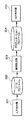
図1は入力デバイスで入力した画像を出力デバイスで出力する際のCMSの処理フローを示す図である。 FIG. 1 is a diagram showing a processing flow of CMS when an image input by an input device is output by an output device.
入力デバイスに依存する入力色空間201は、ソースプロファイル202によって、絶対色空間203へ変換される。そして、絶対色空間203は、デスティネーションプロファイル204によって、出力デバイスに依存する出力色空間205へ変換される。ここで、ソースプロファイル202は入力色空間を絶対色空間に変換するプロファイル、デスティネーションプロファイル204は絶対色空間を出力色空間に変換するプロファイルを示し、現在、International Color Consortium (ICC)が規定するフォーマットであるICCプロファイルが多く使われている。
The
図2はICCプロファイルのデータ表現形式の一例を示す図である。プリンタで用いられるプロファイルは、図2に示すように、色空間の変換をルックアップテーブル(以下「LUT」と呼ぶ)で表現する場合が多い。図2(A)はデバイスに依存するCMYKデータをデバイスに依存しないLabデータに変換するためのLUT、図2(B)はデバイスに依存しないLabデータをデバイスに依存するCMYKデータに変換するためのLUTである。 FIG. 2 is a diagram illustrating an example of a data expression format of the ICC profile. As shown in FIG. 2, a profile used in a printer often expresses color space conversion by a look-up table (hereinafter referred to as “LUT”). Fig. 2 (A) is a LUT for converting device-dependent CMYK data into device-independent Lab data, and Fig. 2 (B) is a diagram for converting device-independent Lab data into device-dependent CMYK data. LUT.
上記のICCプロファイルは、通常、デバイスの製品出荷時に配布されたり、機器に組み込まれていたりする。しかし、どのようなデバイスも経時変化による特性変動が避けられず、特性が変動したデバイスに対して初期のICCプロファイルが最適なものであるとは言い難い場合がある。また、同じデバイスに同一プロファイルを用いたとしても、デバイスの個体差により、必ずしも同じ色味の画像が得られるとは限らない。複数のデバイス間で色味が異なる状態は、複数のプリンタで同じ画像を分散出力するクラスタプリント環境において、とくに問題になる。これは、同種類のプリンタで同じ画像を出力すれば、当然、同じ色味の画像が出力されるという期待があるからである。 The above ICC profile is usually distributed when a device is shipped, or is incorporated in a device. However, in any device, characteristic variation due to aging is unavoidable, and it may be difficult to say that the initial ICC profile is optimal for a device whose characteristics have changed. Even if the same profile is used for the same device, an image with the same color is not always obtained due to individual differences between devices. The state in which the colors are different among a plurality of devices is particularly problematic in a cluster print environment in which the same image is distributed and output by a plurality of printers. This is because there is an expectation that if the same image is output by the same type of printer, an image having the same color will be output.
このようなデバイスの経時変化や個体差の問題に対処するために、ICCプロファイルを、ある時点で、また、各デバイスごとに再作成すれば、あの時点で、また、デバイスごとに最適な色再現を得ることができる。 In order to deal with such problems of device aging and individual differences, if an ICC profile is re-created at a certain point and for each device, the optimal color reproduction at that point and for each device Can be obtained.
しかし、多くのICCプロファイル作成ツールは、多数の色パッチ(一般に1000パッチ程度)をプリントし測色した後、プロファイル作成の計算を行うので、プロファイルの再作成には時間がかかる。さらに、複数のデバイス分、多数の色パッチのプリント、測色、計算の一連の操作を行えば、さらに時間がかかることになる。このため、電子写真方式のカラープリンタなど、日々、デバイス特性が変動し易いデバイスは、手軽に、日常的にプロファイルを再作成することは難しい。 However, since many ICC profile creation tools print a large number of color patches (generally about 1000 patches) and perform color measurement and then perform profile creation calculations, it takes time to recreate the profile. Furthermore, if a series of operations of printing, colorimetry, and calculation of a large number of color patches for a plurality of devices is performed, it takes more time. For this reason, it is difficult to easily recreate a profile on a daily basis for a device whose device characteristics tend to fluctuate every day, such as an electrophotographic color printer.
本発明は、比較的少数のパッチによりプロファイルを生成することを目的とする。 The present invention aims to generate a profile with a relatively small number of patches.
本発明は、前記の目的を達成する一手段として、以下の構成を備える。 The present invention has the following configuration as one means for achieving the above object.
本発明にかかる画像処理は、入力色空間の画像データを絶対色空間を介して出力色空間の画像データに変換するプロファイルを生成する際に、前記入力色空間に応じた色再現範囲に含まれる色値の、多次色で構成されるパッチデータを作成し、前記パッチデータに対応する測色値を取得し、前記プロファイルに含まれる前記出力色空間から前記絶対色空間への第一の変換データを用いて、前記パッチデータに対する前記絶対色空間の基準値を算出し、前記パッチデータに対応する測色値と前記パッチデータに対する基準値を利用して、前記プロファイルに含まれる前記絶対色空間から前記出力色空間への第二の変換データを更新することを特徴とする. The image processing according to the present invention is included in a color reproduction range corresponding to the input color space when generating a profile for converting the image data in the input color space into image data in the output color space via the absolute color space. Create patch data composed of multi-order colors of color values, obtain colorimetric values corresponding to the patch data, and first convert the output color space included in the profile into the absolute color space A reference value of the absolute color space for the patch data is calculated using data, and the absolute color space included in the profile is calculated using a colorimetric value corresponding to the patch data and a reference value for the patch data. The second conversion data from the output color space is updated.
本発明によれば、比較的少数のパッチによりプロファイルを生成することができる。 According to the present invention, a profile can be generated with a relatively small number of patches.
以下、本発明にかかる実施例の画像処理を図面を参照して詳細に説明する。 Hereinafter, image processing according to an embodiment of the present invention will be described in detail with reference to the drawings.
[構成]
図3は実施例1の画像処理システムの構成例を示すブロック図である。
[Constitution]
FIG. 3 is a block diagram illustrating a configuration example of the image processing system according to the first embodiment.
オフィス10内のネットワーク108には、複合機(MFP)101、102、マネージメントPC104、クライアントPC 105、106などが接続されている。この環境において、クライアントPC105、106のユーザは、様々なアプリケーションを使用して必要に応じてプリントを指示する。プリントが指示されると、当該PCにインストールされたプリンタドライバは、アプリケーションから供給されるデータからページ記述言語(PDL)により記述したPDLデータを生成し、ユーザが指定するMFPへ送信する。MFP 101、102は、ネットワーク108を経由して送られてくるPDLデータをプリンタエンジンが処理可能な形式に変換してプリンタエンジンに供給する。
A
マネージメントPC 104は、Universal Serial Bus (USB)やIEEE1394などのシリアルバス111を介して接続されている測色機103で得た測色値の処理や、プロファイルの更新処理、MFPへのプロファイルのアップロードおよびダウンロードを担当する。
The
なお、マネージメントPC 104、クライアントPC 105、106は、図には示さないが、画像や画像処理用のソフトウェアなどを記憶するメモリ、モニタ、キーボードやマウスなどの入力デバイス、シリアルバスインタフェイスなどを有し、ディジタルカメラなどの画像入力デバイスから、あるいは、ネットワーク108を介して接続可能なサーバ装置から画像を入力し、入力画像に画像処理を施し、画像処理後の画像をMFP101、102やサーバ装置に出力することができる。それらの処理は、マネージメントPCやクライアントPCのCPUが、RAMをワークメモリとして実行することは言うまでもない。あるいは、マネージメントPC 104は、後述するプロファイルの更新処理用の装置としてMFPに付随させてもよい。
Although not shown in the figure, the management PC 104 and
図4はMFPの構成例を示すブロック図である。 FIG. 4 is a block diagram illustrating a configuration example of the MFP.
画像読取部301は、オートドキュメントフィーダによって供給される原稿に光源の光を照射し、原稿の反射像をレンズを介して固体撮像素子上に結像し、固体撮像素子からラスタ状に出力される画像読取信号によって、例えば解像度600 dpiの画像データを取得する。通常の複写機能を実行する際、データ処理部305は、画像処理部305bにより画像データを記録信号に変換して記録装置303に出力し、記録紙上に複写画像を形成する。また、複数枚の複写画像を形成する場合、データ処理部305は、一旦、一頁分の記録信号を記憶部302に格納し、記録部303の動作に合わせて、記憶部302から読み出した記録信号を記録部303へ供給することで複数枚の複写画像を形成する。
An
一方、プリント機能を実行する際は、データ処理部305は、ネットワーク108を経由してネットワークインタフェイス(I/F) 306が受信したPDLデータを記憶部302にスプールするとともに、記憶部302から読み出したPDLデータに、PDL処理部305aによりレンダリング処理およびICCプロファイルを使用する色変換処理を施し、さらに、画像処理部305bによりUCR、マスキング処理、ガンマ補正などの画像処理を行って記録信号に変換し、記録信号を記録装置303に出力して記録紙上に複写画像を形成する。
On the other hand, when executing the print function, the
操作部304は、キーボードやスイッチ、LCDパネルなどに表示したユーザインタフェイスによりオペレータの指示入力を受け付けるとともに、指示入力の状態、MFPの動作(画像処理や画像形成の進行状態)やエラー(ジャム、紙切れ、トナーの有無)などのステータスを表示する。
The
[色変換処理]
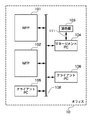
図5はPDL処理部305aの色変換処理を示す図である。
[Color conversion processing]
FIG. 5 is a diagram showing the color conversion processing of the
PDL処理部305aは、プリンタドライバまたはレンダリング処理によってRGB色空間からCMYK色空間に変換されたcmykデータ401を、ソースプロファイル402を用いてL*a*b*色空間のLabデータ403に変換し、次に、デスティネーションプロファイル404を用いてCMYKデータ405に変換する。
The
ソースプロファイル402には、CMYK色空間のデータを入力する場合、印刷機をシミュレートするシミュレーションプロファイルを指定するのが一般的である。そのような例として、DIC(大日本インク、日本標準)、SWOP(USA標準)などの標準インク設定の印刷機プロファイルが挙げられる。これにより、印刷機のCMYK色値が絶対色空間(この例ではL*a*b*色空間)の色値に変換され、さらに、記録部303のプロファイルであるデスティネーションプロファイル404によって記録部303のCMYK色空間のCMYKデータ405が得られる。なお、cmykデータ401とCMYKデータ405は、データの次元は同一だが、それぞれ違うデバイスの色空間で定義されたデータであるから、その値は異なる。
In the
勿論、PDL処理部305aは、色変換処理を行わずに、cmykデータ401を直接、CMYKデータ405として出力することも可能である。
Of course, the
ソースプロファイル402およびデスティネーションプロファイル404は、記憶部302に保持されていて、データ処理部305は必要に応じてプロファイルを読み出し処理を行う。また、データ処理部305は、マネージメントPC 104のプロファイルのアップロード、ダウンロード要求に対して、記憶部302から読み出したプロファイルをマネージメントPC 104に送信したり、マネージメントPC 104から受信したプロファイルを記憶部302に格納することができる。
The
また、PDL処理部305aは、RGB色空間からCMYK色空間に変換されていないデータを扱うこともできる。その場合、ソースプロファイル402には、例えばsRGB色空間用のsRGBモニタプロファイルなどのRGBプロファイルを用いて、RGBデータをLabデータ403に変換すればよい。
The
[マネージメントPC]
図6はマネージメントPC 104が行う処理を説明するブロック図である。なお、ここで説明するマネージメントPC 104の処理はすべてソフトウェアで実現される。つまり、マネージメントPC 104のCPUは、マネージメントPC 104に組み込まれたハードディスクドライブ(HDD)などの不揮発性メモリから読み出し、マネージメントPC 104のRAMにストアしたプログラムを実行することで、すべての処理を実現する。
[Management PC]
FIG. 6 is a block diagram for explaining processing performed by the
測色機103は、試料に光を照射し、その反射光をセンサで読み取って得られる分光感度を、Lab値に変換した測定値を出力する。測色機I/F 1001は、シリアルバス111を介して、測色機103とインタフェイスするモジュールで、シリアルバスインタフェイスモジュールおよび測色機ハンドリングモジュールで構成され、測色機103を制御して、測色機103が出力するLab値を受信する。
The
プロファイル更新部1002は、MFPから受信したプロファイルのLUTを、そのMFPが出力したパッチの測色値(Lab値)に基づき、そのMFPに最適なものに更新する処理を行うモジュールである。この処理については後で詳細に説明する。
The
プロファイル送受信部1003は、MFPの更新すべきプロファイルをネットワークI/F 1005を介して送受信するモジュールである。MFPからプロファイルを受信する際は、デスティネーションプロファイル送信要求コマンドをMFPに送信し、このコマンドに応答してMFPが送信するプロファイルを受信する。また、更新したプロファイルをMFPに送信する際は、プロファイル送信コマンドにプロファイルを添付してMFPに送信する。
The profile transmission /
パッチ出力部1004は、プロファイル更新処理部1002で使用するCMYK値に対するLab値を得るためのCMYKパッチデータを作成し、あるいは、マネージメントPC 104のHDDなどからCMYKパッチデータを読み出し、ネットワークI/F 105を介して、パッチプリントコマンドにCMYKパッチデータを添付してMFPに送信するモジュールである。
The
グラフィックユーザインタフェイス(GUI) 1006は、モニタに表示したユーザインタフェイスに対するユーザの指示をキーボードおよびマウスなどの入力デバイスを介して受け取り、制御部1007へ供給する。例えば、プロファイルの送受信においてはMFPやプロファイルを特定するためのユーザ指示を、パッチ出力においてはMFPを特定するためのユーザ指示を受け付け、測色においては測色状態を表示し測色の開始などを示すユーザ指示を受け付ける。つまり、上述した各部の動作は、GUI 1006に入力されるユーザ指示に従い、制御部1007が制御するものである。
A graphic user interface (GUI) 1006 receives a user instruction for the user interface displayed on the monitor via an input device such as a keyboard and a mouse, and supplies the received instruction to the
[プロファイル更新処理]
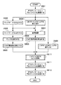
図7はプロファイル更新処理の概要を示すフローチャートで、ユーザのプロファイル更新指示に応じて、制御部1007が実行する処理である。
[Profile update processing]
FIG. 7 is a flowchart showing an outline of the profile update process, which is executed by the
まず、プロファイル送受信部1003を制御し、ユーザが指定するMFP(ここではMFP 101とする)から、MFP 101が標準に用いるデスティネーションプロファイル(ICCプロファイル)を受信する(S501)。
First, the profile transmission /
次に、パッチ出力部1004を制御して、受信したデスティネーションプロファイルを利用して、出力するパッチデータを作成する(S502)。このパッチデータは、およそ百色の多次色で構成したデータで、CMYKの数値データおよびその画像データとで構成する。このパッチデータの作成方法の詳細は後述する。
Next, the
次に、パッチ出力部1004を制御して、MFP 101にパッチデータの送信し、パッチをプリントさせる(S503)。ただし、パッチのプリントは、図5に示すソースプロファイル402、デスティネーションプロファイル404を介さずに、パッチデータ(cmykデータ401)をそのままCMYKデータ405として、プリントを実行するようにMFP 101に指示する。
Next, the
ユーザが、MFP 101がプリントしたパッチを測色機103の測色部にセットし、測色の開始を指示すると、測色機I/F 1001を制御して測色を行い(S504)、測色値(Lab値)を取得する(S505)。
When the user sets the patch printed by the
一方、プロファイル更新処理部1002を制御して、ステップS506からS511までの処理を行わせる。つまり、デスティネーションプロファイルに含まれる、CMYK値をLab値に変換するLUT(以下「CMYK→Lab LUT」と呼ぶ)を取り出し(S506)、ステップS502で作成したパッチの数値データとCMYK→Lab LUTを用いて補間演算を行い(S507)、Lab基準値を算出する(S508)。また、デスティネーションプロファイルからLab値をCMYK値に変換するLUT(以下「Lab→CMYK LUT」と呼ぶ)を取り出す(S509)。
On the other hand, the profile
そして、測色値(Lab値)、Lab基準値、Lab→CMYK LUTが揃うと、それらを用いてLab→CMYK LUTを更新し(S510)、更新されたLab→CMYK LUTによりデスティネーションプロファイルを更新する(S511)。 When the colorimetric value (Lab value), Lab reference value, and Lab → CMYK LUT are available, the Lab → CMYK LUT is updated using them (S510), and the destination profile is updated with the updated Lab → CMYK LUT. (S511).
次に、プロファイル送受信部1003を制御して、プロファイル送信コマンドに、更新したデスティネーションプロファイルを添付してMFP 101に送信し、MFP 101に格納させる(S512)。
Next, the profile transmission /
以上の処理によって更新されたデスティネーションプロファイルを、実際の印刷時に利用することで、デバイス(この例ではMFP)の状態に左右されず、適切な色味の画像を得ることが可能になる。 By using the destination profile updated by the above processing at the time of actual printing, it is possible to obtain an image with an appropriate color regardless of the state of the device (MFP in this example).
以下では、上記の各処理について詳細に説明する。 Below, each said process is demonstrated in detail.
●補間演算(S507)
補間演算は、パッチデータのCMYK値に対するLab値を求める処理である。つまり、CMYK→Lab LUTには、あるCMYK値に対応するLab値が記述されているので、このLUTを用いて補間演算を行えば、パッチデータのCMYK値に対するLab値を計算することができる。
Interpolation calculation (S507)
Interpolation calculation is processing for obtaining Lab values for CMYK values of patch data. That is, since the Lab value corresponding to a certain CMYK value is described in the CMYK → Lab LUT, the Lab value for the CMYK value of the patch data can be calculated by performing an interpolation operation using this LUT.
図8は補間演算(S507)の詳細を説明する図である。 FIG. 8 is a diagram for explaining the details of the interpolation calculation (S507).
まず、K値を基準として、CMYK→Lab LUTのデータをグループ化する(S702)。LUTの入力側色値は色値を示すとともに、LUTへの入力格子点であり、その色値は段階的に増える。従って、例えばCMYKがそれぞれ17段階であるとすると、K値を基準にしてグループ化する場合、17×17×17×17個の格子点は、17組の17×17×17格子点グループに分類される。 First, CMYK → Lab LUT data is grouped based on the K value (S702). The color value on the input side of the LUT indicates a color value and is an input grid point to the LUT, and the color value increases step by step. Therefore, for example, assuming that CMYK has 17 levels, when grouping based on K value, 17 × 17 × 17 × 17 lattice points are classified into 17 sets of 17 × 17 × 17 lattice points. Is done.
次に、一つのパッチのCMYK値を取り出し(S703)、取り出したCMYK値のK値に着目する(S704)。なお、注目するK値を「K1」とする。 Next, the CMYK value of one patch is extracted (S703), and attention is paid to the K value of the extracted CMYK value (S704). Note that the K value of interest is “K1”.
次に、グループ化したLUTデータのK値に着目して、K1を囲むグループを二つ抽出する(S705)。例えば、色の階調が256段階で、17段階のLUTがあり、K1=20の場合、K=16およびK=32のグループを取り出す。ここで、K値が小さいグループをKa、K値が大きいグループをKbとする。そして、Ka、Kbそれぞれのグループについて、パッチのCMY値に対するLab値を線形補間により算出する(S706、S707)。この線形補間には三次元の既知の手法を用いる。 Next, paying attention to the K value of the grouped LUT data, two groups surrounding K1 are extracted (S705). For example, if the color gradation is 256 levels and there are 17 levels of LUTs, and K1 = 20, then K = 16 and K = 32 groups are extracted. Here, a group with a small K value is Ka, and a group with a large K value is Kb. Then, for each of Ka and Kb groups, the Lab value for the CMY value of the patch is calculated by linear interpolation (S706, S707). A three-dimensional known method is used for this linear interpolation.
次に、ステップS706、S707の線形補間結果(つまり、CMYKa値とCMYKb値に対応するLab値)から、K値に対する一次元の線形補間を行い、CMYK値に対応するLab値(Lab基準値)を得る(S708)。 Next, one-dimensional linear interpolation is performed on the K value from the linear interpolation results of Steps S706 and S707 (that is, the Lab value corresponding to the CMYKa value and the CMYKb value), and the Lab value (Lab reference value) corresponding to the CMYK value. (S708).
そして、ステップS709の判定により、すべてのパッチデータ(CMYK値)に対するLab基準値の算出が終了するまで、ステップS703からS708の処理を繰り返す。 Then, the process from step S703 to step S708 is repeated until the Lab reference value calculation for all patch data (CMYK values) is completed by the determination in step S709.
●Lab→CMYK LUTの更新
デスティネーションプロファイルは、実際の印刷時に、絶対色空間のデータを出力デバイスの色空間に変換する部分を担当する。従って、デスティネーションプロファイルのLab→CMYK LUTを適切に調整・更新すれば、出力デバイスのデバイス特性の変動や、個体差による出力結果の違いを吸収することができる。
● Lab → CMYK LUT Update The destination profile is responsible for converting the absolute color space data to the output device color space during actual printing. Therefore, if the destination profile Lab → CMYK LUT is appropriately adjusted and updated, it is possible to absorb variations in device characteristics of the output device and differences in output results due to individual differences.
図9はLab→CMYK LUTの更新処理の詳細を説明するフローチャートである。なお、図9に示すメモリ812および813は、マネージメントPC 104のRAMまたはHDDの所定領域に割り当てられている。
FIG. 9 is a flowchart for explaining the details of the Lab → CMYK LUT update process. Note that the
まず、Lab→CMYK LUTの一つのLab格子点の色値(Lab格子点データ)を取り出す(S801)。なお、Lab格子点データは、その増分が固定されているデータである。図10はLab空間上の格子点データを示す図である。例えば、Lab→CMYK LUTがLab各33段階のLUTである場合、33×33×33個ある格子点の一つをステップS801で取り出す。 First, the color value (Lab grid point data) of one Lab grid point of Lab → CMYK LUT is extracted (S801). The Lab grid point data is data whose increment is fixed. FIG. 10 is a diagram showing lattice point data on the Lab space. For example, if Lab → CMYK LUT is a LUT of 33 stages for each Lab, one of 33 × 33 × 33 lattice points is extracted in step S801.
次に、ステップS801で取り出したLab格子点データに最も近い、メモリ812に格納されたパッチデータのLab基準値を探索する(S802)。図11はLab格子点データ、Lab基準値および測色値の関係を示す図で、図には基準値1と基準値2が存在するが、注目しているLab格子点データには基準値1の方が近いので、基準値1が探索結果になる。
Next, the Lab reference value of the patch data stored in the
次に、探索されたLab基準値と、対応する測色値の差D(図11の例ではLab基準値1と測色値1の差)を計算する(S803)。この差Dを用いてLab格子点データを更新するが、パッチデータの数が少ないと、Lab格子点データから遠く離れたLab基準値が探索されることが多くなる。Lab格子点データから遠く離れたLab基準値に更新が影響されることは望ましくないので、Lab基準値とLab格子点データの距離を算出し、距離に応じた重み付けを行う(S804)。例えば、距離として三次元空間上でのユークリッド距離を採用し、下式のように重み付けする。
D・W = D/dist(5+1) …(1)
ここで、Wは重み
distはLab基準値との距離を格子点三つ分の距離で正規化したもの
Next, the difference D between the searched Lab reference value and the corresponding colorimetric value (the difference between Lab reference value 1 and colorimetric value 1 in the example of FIG. 11) is calculated (S803). The Lab grid point data is updated using this difference D, but if the number of patch data is small, Lab reference values far from the Lab grid point data are often searched. Since it is not desirable that the update is affected by the Lab reference value far from the Lab grid point data, the distance between the Lab reference value and the Lab grid point data is calculated and weighted according to the distance (S804). For example, the Euclidean distance in the three-dimensional space is adopted as the distance, and weighted as in the following equation.
D ・ W = D / dist (5 + 1) … (1)
Where W is the weight
dist is the distance normalized to the Lab reference value normalized by the distance of three grid points
そして、ステップS805の判定により、LUTのすべてのLab格子点に対する処理が終了するまで、ステップS801からS804を繰り返す。 Then, steps S801 to S804 are repeated until the processing for all Lab lattice points of the LUT is completed by the determination in step S805.
図12はLab格子点に対する、Lab基準値と測色値の差Dを求めた結果を説明する図で、矢印は測色値からLab基準値へ向かう方向ベクトルを表す。この方向ベクトルの分、格子点のLab値をずらすことになる。しかし、Lab格子点に対して探索されたLab基準値により、極端な方向・大きさの方向ベクトルが存在する可能性がある。図13の例では、楕円で囲った格子点の方向ベクトルが、周囲の方向ベクトルに比べて極端な大きさをもつように描いてあるが、このような方向ベクトルが存在する場合は、格子点のLab値は極端に更新され、擬似輪郭が発生する原因になる。 FIG. 12 is a diagram for explaining the result of obtaining the difference D between the Lab reference value and the colorimetric value with respect to the Lab grid point. The Lab value of the grid point is shifted by this direction vector. However, there is a possibility that a direction vector having an extreme direction / size may exist depending on the Lab reference value searched for the Lab lattice point. In the example of FIG. 13, the direction vector of the lattice point surrounded by the ellipse is drawn so as to have an extreme size compared to the surrounding direction vector. However, if such a direction vector exists, the lattice point The Lab value is extremely updated, which causes a pseudo contour.
そこで、求めた差D・Wに対してスムージング処理を行い(S806)、格子点のLab値が極端に更新されることを防ぐ。スムージング方法は、例えば、注目格子点を中心とする5×5×5の範囲の格子点に対応する差D・Wを合計して、その平均を算出する方法、注目格子点に対応する差D・Wを数倍し、他の格子点に対応する差D・Wと合計して平均を算出する方法、などが挙げられる。 Therefore, smoothing processing is performed on the obtained difference D · W (S806) to prevent the Lab values of the grid points from being extremely updated. The smoothing method is, for example, a method of summing the differences D · W corresponding to the lattice points in the range of 5 × 5 × 5 centered on the target lattice point and calculating the average, the difference D corresponding to the target lattice point A method of calculating the average by multiplying W by several times and summing it with the difference D · W corresponding to other grid points, etc.
次に、スムージング処理した差D'をLab格子点データに加えて格子点を更新し(S807)、更新した格子点からLab格子点データを一つ取り出す(S808)。更新された格子点に対するCMYK値がわかればディスティネーションプロファイルのLab→CMYK LUTの更新が可能になる。そこで、メモリ813に格納された更新前のLab→CMYK LUTがLabからCMYKへの変換を記述したLUTであることを利用して、更新された格子点のLab値に対して三次元の線形補間演算を行い、CMYK値を算出する(S809)。
Next, the smoothed difference D ′ is added to the Lab grid point data to update the grid points (S807), and one Lab grid point data is extracted from the updated grid points (S808). If the CMYK value for the updated grid point is known, the destination profile Lab → CMYK LUT can be updated. Therefore, using the fact that the Lab → CMYK LUT before update stored in the
そして、ステップS810の判定により、LUTのすべてのLab格子点に対する処理が終了するまで、ステップS808およびS805を繰り返し、すべてのLab格子点のCMYK値が求まると、その結果によりLab→CMYK LUTを更新する(S811)。 Then, as determined in step S810, steps S808 and S805 are repeated until the processing for all Lab lattice points of the LUT is completed. When CMYK values of all Lab lattice points are obtained, Lab → CMYK LUT is updated based on the result. (S811).
このような処理を、MFP 101だけではなく、MFP 102にも同様に定期的に適用することで、デバイス特性の変動や個体差による色味の違いを大幅に軽減することができる。従って、複数台のデバイスに同一のデータを供給するクラスタプリントにおいて、電子写真方式のプリンタのようにデバイス特性の変動による色味の変化が激しい印刷方式でも、色味が揃ったプリントアウトを得ることが可能になる。この場合、各デバイスに内蔵されているプロファイルは標準では同じものであるから、CMYK→Lab LUT(つまり基準状態)は共通であり、各デバイスのプロファイルのLab→CMYK LUTを基準状態に合わせるように更新することになる。
By periodically applying such processing not only to the
また、上記の更新処理を行ったデスティネーションプロファイルを利用して画像をプリントする場合、その画像データはCMYKデータである必要はない。図13は、実際の印刷時における、PDL処理部305aの色変換処理を示す図であるが、画像データ901をLabデータ903に変換するソースプロファイル902が存在すれば、更新されたディスティネーションプロファイル904を用いてCMYKデータ905を作成することができる。例えばソースプロファイル902がRGBデータをLabデータに変換するものであれば、画像データ901はRGBデータでよい。勿論、更新されたディスティネーションプロファイルが扱う絶対色空間(例ではLab)に入力色空間を変換するものであれば、ソースプロファイルはどのようなものを用いても構わない。
In addition, when an image is printed using the destination profile subjected to the above update process, the image data need not be CMYK data. FIG. 13 is a diagram showing the color conversion processing of the
[パッチデータの生成方法]
上述したLab→CMYK LUTの更新処理は、格子点空間であるLab色空間で、Lab基準値と測色値の差分Dを求め、差分Dを重み付けして、格子点のLab値にフィードバックする。この場合、格子点間で補正精度の偏りが出るのを避けるには、測色値とLab基準値の差分ベクトルがLab空間で均等に分布するようにパッチを構成することが望ましい。
[Patch data generation method]
In the Lab → CMYK LUT update process described above, the difference D between the Lab reference value and the colorimetric value is obtained in the Lab color space, which is the lattice point space, the difference D is weighted, and fed back to the Lab value of the lattice point. In this case, it is desirable to configure the patch so that the difference vector between the colorimetric value and the Lab reference value is evenly distributed in the Lab space in order to avoid deviations in the correction accuracy between the lattice points.
そこで、Lab色空間で均等なLab値を発生し、更新対象であるプロファイル自体のLab→CMYK LUTを利用して、そのLab値に対応するCMYK値を求めてパッチデータに採用すれば、Lab色空間でほぼ均等な分布の測色値が得られるパッチが構成できる。 Therefore, by generating uniform Lab values in the Lab color space, using the Lab → CMYK LUT of the profile to be updated, obtaining the CMYK value corresponding to the Lab value and applying it to the patch data, the Lab color A patch that can obtain colorimetric values with a substantially uniform distribution in space can be configured.
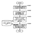
図14はパッチデータの生成処理を示すフローチャートである。 FIG. 14 is a flowchart showing patch data generation processing.
まず、Lab色空間に均等に分布するN×N×N個の格子点を発生する(S1601)。こうして発生したLab格子点はLab色空間全体を覆うが、実際には使用しない格子点が多数存在するので、使用すべき格子点のLab値を抜き出す(S1602)。 First, N × N × N lattice points that are evenly distributed in the Lab color space are generated (S1601). The generated Lab grid points cover the entire Lab color space, but since there are many grid points that are not actually used, Lab values of the grid points to be used are extracted (S1602).
使用すべき格子点の選定には、実際の出力処理で想定されるソースプロファイルの色再現範囲にあるものを抜き出せばよい。例えば、sRGB色空間をソースプロファイルとして想定する場合、その色再現域は、一般的な電子写真方式のプリンタよりは広いものの、Lab色空間全体を占めることはない。従って、実際の出力処理では、sRGB色空間の外側にある格子点のLab値をソースプロファイル側で出力することはなく、言い換えれば、デスティネーションプロファイルのLab→CMYK LUTの入力になることはない。このような理由から、発生したN×N×N個の格子点のうち、sRGB色空間の中に入っているものを選んで、その測色値の周辺のLab→CMYK LUTの調整を行えば、sRGB色空間がソースプロファイルとして使用される状況の下では色味を合わせるのに充分である。この関係を利用して、パッチの個数を効果的に削減することができる。 In selecting a grid point to be used, a grid point within the color reproduction range of the source profile assumed in actual output processing may be extracted. For example, when an sRGB color space is assumed as a source profile, the color reproduction range is wider than that of a general electrophotographic printer, but does not occupy the entire Lab color space. Therefore, in actual output processing, Lab values of grid points outside the sRGB color space are not output on the source profile side, in other words, they are not input from the destination profile to the Lab → CMYK LUT. For this reason, it is possible to select the N × N × N grid points that have been generated in the sRGB color space and adjust Lab → CMYK LUT around the colorimetric value. In the situation where the sRGB color space is used as the source profile, it is sufficient to match the color. Using this relationship, the number of patches can be effectively reduced.
次に、受信したデスティネーションプロファイルからLab→CMYK LUTを取り出し(S1603)、抜き出した格子点のLab値から、Lab→CMYK LUTを用いる補間演算により、CMYK値(パッチデータ)を生成する(S1604)。 Next, Lab → CMYK LUT is extracted from the received destination profile (S1603), and CMYK values (patch data) are generated from the Lab values of the extracted grid points by interpolation using Lab → CMYK LUT (S1604). .
図15はパッチデータの生成処理における、パッチデータ生成用のLab格子点(×印)、Lab→CMYK LUTのLab格子点(●印)、ソースプロファイルの色再現範囲(実線)を二次元的に示す図である。図に示すように、Lab→CMYK LUTの格子点よりも少ない数のパッチデータ生成用の格子点を発生し、さらに、ソースプロファイルの色再現範囲内にあるものを取り出す。 Figure 15 shows two-dimensionally the Lab grid points for patch data generation (× mark), Lab → CMYK LUT Lab grid points (● mark), and source profile color reproduction range (solid line) in the patch data generation process. FIG. As shown in the figure, a smaller number of grid points for patch data generation than the Lab → CMYK LUT grid points are generated, and those within the color reproduction range of the source profile are extracted.
ここで、Lab→CMYK LUTが33×33×33の格子点をもつとすると、LUT全体で35837個の格子点をもつことになる。35837個の格子点のLab値に対応するパッチを形成すれば、Lab色空間に対応する測色値がまんべんなく得られることになるが、現実的なパッチ数とは言えない。そこで、パッチデータ生成用の格子点を9×9×9にすればパッチ数は729個になる。さらに、ソースプロファイルの色再現範囲に存在する格子点を取り出すことで、パッチ数を削減する。ソースプロファイルの色空間をsRGB色空間と想定した場合、Lab色空間(L=0〜100、 a=-128〜128、 b=-128から128)の体積に対して、sRGB色空間の体積は大凡1/7〜1/8程度でしかない。従って、729個のパッチを90〜105個程度に削減することができる。 Here, if the Lab → CMYK LUT has 33 × 33 × 33 lattice points, the entire LUT has 35837 lattice points. If patches corresponding to Lab values of 35837 grid points are formed, colorimetric values corresponding to the Lab color space can be obtained evenly, but this is not a realistic number of patches. Therefore, if the grid points for generating patch data are 9 × 9 × 9, the number of patches is 729. Furthermore, the number of patches is reduced by extracting grid points existing in the color reproduction range of the source profile. Assuming that the color space of the source profile is sRGB color space, the volume of sRGB color space is the volume of Lab color space (L = 0-100, a = -128-128, b = -128 to 128) Only about 1/7 to 1/8. Therefore, 729 patches can be reduced to about 90 to 105.
勿論、色再現精度の向上を図って格子点の数をより多くしても構わないが、その場合、測色に要する時間が長くなる。また、ソースプロファイルの色空間としてsRGB色空間を想定したが、他のRGB色空間でも構わない。CMYKデータのみをプリントするような用途であれば、DICやSWOPなどの印刷標準プロファイルの色再現域を採用することも可能で、RGB色空間よりもCMYK色空間の方が狭い場合が多いため、よりパッチデータの個数を減らすことができる。 Of course, the number of grid points may be increased by improving the color reproduction accuracy, but in this case, the time required for color measurement becomes longer. Further, although the sRGB color space is assumed as the color space of the source profile, other RGB color spaces may be used. For applications that print only CMYK data, it is possible to adopt the color reproduction gamut of standard printing profiles such as DIC and SWOP, and the CMYK color space is often narrower than the RGB color space. The number of patch data can be further reduced.
このように、MFPなどのデバイスに内蔵、または、配布される色再現特性を記述したプロファイルに基づき、簡便かつ高精度にプロファイルの修正を行うことができる。従って、常に、最適なカラーマッチングを行うことができる。そして、複数のデバイスに適用すれば、それら複数のデバイスの色再現性を合わせ込むことが可能である。 As described above, the profile can be easily and accurately corrected based on the profile describing the color reproduction characteristics built in or distributed in a device such as an MFP. Therefore, optimal color matching can always be performed. When applied to a plurality of devices, the color reproducibility of the plurality of devices can be adjusted.
以下、本発明にかかる実施例2の画像処理を説明する。なお、本実施例において、実施例1と略同様の構成については、同一符号を付して、その詳細説明を省略する。 The image processing according to the second embodiment of the present invention will be described below. Note that in this embodiment, the same reference numerals as those in the first embodiment denote the same parts, and a detailed description thereof will be omitted.
以下では、Lab→CMYK LUTを更新する他の方法を説明する。図16は実施例2のLab→CMYK LUTの更新処理の詳細を説明するフローチャートである。 In the following, another method for updating Lab → CMYK LUT will be described. FIG. 16 is a flowchart illustrating details of the Lab → CMYK LUT update process according to the second embodiment.
まず、Lab→CMYK LUTの一つのLab格子点の色値(Lab格子点データ)を取り出し(S1401)、取り出したLab格子点データの近傍の範囲(例えば、Lab格子点データを中心とする5×5×5の範囲など、以下「条件範囲」と呼ぶ)を設定し(S1402)、メモリ812に格納されたパッチデータのLab基準値が条件範囲内か否かを判定する(S1403)。
First, a color value (Lab grid point data) of one Lab grid point of Lab → CMYK LUT is extracted (S1401), and a range in the vicinity of the extracted Lab grid point data (for example, 5 × centered on Lab grid point data) (Hereinafter referred to as “condition range”, such as a 5 × 5 range) is set (S1402), and it is determined whether the Lab reference value of the patch data stored in the
図17はLab格子点データ、条件範囲、Lab基準値、測色値の関係を説明する図である。 FIG. 17 is a diagram for explaining the relationship among Lab grid point data, condition ranges, Lab reference values, and colorimetric values.
そして条件範囲内に含まれるLab基準値がある場合は、それらLab基準値と対応する測色値の差Dを求め(S1406)、その差Dの平均を算出する(S1407)。図17の例では二つのLab基準値が条件範囲に含まれるため、それぞれ測色値との差を求めて平均を算出する。このようにすれば、実施例1のスムージング処理と同様の効果が得られ、擬似輪郭を防止することができる。 If there are Lab reference values included in the condition range, the difference D between the colorimetric values corresponding to the Lab reference values is obtained (S1406), and the average of the differences D is calculated (S1407). In the example of FIG. 17, since two Lab reference values are included in the condition range, the difference between each color measurement value is obtained and the average is calculated. In this way, the same effect as the smoothing process of the first embodiment can be obtained, and pseudo contour can be prevented.
一方、条件範囲内にLab基準値が存在しない場合は、最も近いLab基準値を探索して、そのLab基準値と測色値との差Dを算出し(S1404)、実施例1と同様の方法で、距離に応じた重み付けを行う(S1405)。なお、条件範囲内のLab基準値が存在しない格子点は、色再現範囲外であることが多いから、重みは一律の値(例えば四分の一にするなど)でも構わない。 On the other hand, if the Lab reference value does not exist within the condition range, the closest Lab reference value is searched for, and the difference D between the Lab reference value and the colorimetric value is calculated (S1404). By the method, weighting according to the distance is performed (S1405). Note that grid points where there is no Lab reference value within the condition range are often outside the color reproduction range, and therefore, the weight may be a uniform value (for example, a quarter value).
そして、ステップS1408の判定により、LUTのすべてのLab格子点に対する差の平均値Daまたは重み付けした差D・Wを計算するまで、ステップS1401からS1407を繰り返す。 Steps S1401 to S1407 are repeated until the average value Da or the weighted difference D · W for all Lab grid points of the LUT is calculated by the determination in step S1408.
次に、差の平均値Daまたは重み付けした差D・WをLab格子点データに加えて格子点を更新し(S1409)、更新した格子点からLab格子点データを一つ取り出す(S1410)。更新された格子点に対するCMYK値がわかればディスティネーションプロファイルのLab→CMYK LUTの更新が可能になる。そこで、メモリ813に格納された更新前のLab→CMYK LUTがLabからCMYKへの変換を記述したLUTであることを利用して、更新された格子点のLab値に対して三次元の線形補間演算を行い、CMYK値を算出する(S1411)。
Next, the difference average value Da or the weighted difference D · W is added to the Lab grid point data to update the grid points (S1409), and one Lab grid point data is extracted from the updated grid points (S1410). If the CMYK value for the updated grid point is known, the destination profile Lab → CMYK LUT can be updated. Therefore, using the fact that the Lab → CMYK LUT before update stored in the
そして、ステップS1412の判定により、LUTのすべてのLab格子点に対する処理が終了するまで、ステップS1410およびS1411を繰り返し、すべてのLab格子点のCMYK値が求まると、その結果によりLab→CMYK LUTを更新する(S1413)。 Then, as a result of the determination in step S1412, steps S1410 and S1411 are repeated until the processing for all Lab grid points of the LUT is completed. When CMYK values of all Lab grid points are obtained, Lab → CMYK LUT is updated based on the result. (S1413).
[他の実施例]
なお、本発明は、複数の機器(例えばホストコンピュータ、インタフェイス機器、リーダ、プリンタなど)から構成されるシステムに適用しても、一つの機器からなる装置(例えば、複写機、ファクシミリ装置など)に適用してもよい。
[Other embodiments]
Note that the present invention can be applied to a system including a plurality of devices (for example, a host computer, an interface device, a reader, and a printer), and a device (for example, a copying machine and a facsimile device) including a single device. You may apply to.
また、本発明の目的は、前述した実施例の機能を実現するソフトウェアのプログラムコードを記録した記憶媒体(または記録媒体)を、システムあるいは装置に供給し、そのシステムあるいは装置のコンピュータ(またはCPUやMPU)が記憶媒体に格納されたプログラムコードを読み出し実行することによっても、達成されることは言うまでもない。この場合、記憶媒体から読み出されたプログラムコード自体が前述した実施例の機能を実現することになり、そのプログラムコードを記憶した記憶媒体は本発明を構成することになる。また、コンピュータが読み出したプログラムコードを実行することにより、前述した実施例の機能が実現されるだけでなく、そのプログラムコードの指示に基づき、コンピュータ上で稼働しているオペレーティングシステム(OS)などが実際の処理の一部または全部を行い、その処理によって前述した実施例の機能が実現される場合も含まれることは言うまでもない。 Also, an object of the present invention is to supply a storage medium (or recording medium) on which a program code of software that realizes the functions of the above-described embodiments is recorded to a system or apparatus, and the computer (or CPU or CPU) of the system or apparatus. Needless to say, this can also be achieved by the MPU) reading and executing the program code stored in the storage medium. In this case, the program code itself read from the storage medium realizes the functions of the above-described embodiments, and the storage medium storing the program code constitutes the present invention. Further, by executing the program code read by the computer, not only the functions of the above-described embodiments are realized, but also an operating system (OS) running on the computer based on the instruction of the program code. It goes without saying that a case where the function of the above-described embodiment is realized by performing part or all of the actual processing and the processing is included.
さらに、記憶媒体から読み出されたプログラムコードが、コンピュータに挿入された機能拡張カードやコンピュータに接続された機能拡張ユニットに備わるメモリに書込まれた後、そのプログラムコードの指示に基づき、その機能拡張カードや機能拡張ユニットに備わるCPUなどが実際の処理の一部または全部を行い、その処理によって前述した実施例の機能が実現される場合も含まれることは言うまでもない。 Furthermore, after the program code read from the storage medium is written into a memory provided in a function expansion card inserted into the computer or a function expansion unit connected to the computer, the function is determined based on the instruction of the program code. Needless to say, the CPU of the expansion card or the function expansion unit performs part or all of the actual processing and the functions of the above-described embodiments are realized by the processing.
本発明を上記記憶媒体に適用する場合、その記憶媒体には、先に説明したフローチャートに対応するプログラムコードが格納されることになる。 When the present invention is applied to the storage medium, the storage medium stores program codes corresponding to the flowcharts described above.
Claims (9)
前記入力色空間に応じた色再現範囲に含まれる色値の、多次色で構成されるパッチデータを作成する作成手段と、
前記パッチデータに対応する測色値を取得する取得手段と、
前記プロファイルに含まれる前記出力色空間から前記絶対色空間への第一の変換データを用いて、前記パッチデータに対する前記絶対色空間の基準値を算出する算出手段と、
前記パッチデータに対応する測色値と前記パッチデータに対する基準値を利用して、前記プロファイルに含まれる前記絶対色空間から前記出力色空間への第二の変換データを更新する更新手段とを有することを特徴とする画像処理装置。 An image processing apparatus for generating a profile for converting image data in an input color space into image data in an output color space via an absolute color space,
Creating means for creating patch data composed of multi-order colors of color values included in a color reproduction range according to the input color space;
Obtaining means for obtaining a colorimetric value corresponding to the patch data;
Calculation means for calculating a reference value of the absolute color space for the patch data using first conversion data from the output color space to the absolute color space included in the profile;
Update means for updating second conversion data from the absolute color space to the output color space included in the profile by using a colorimetric value corresponding to the patch data and a reference value for the patch data; An image processing apparatus.
前記更新前の第二の変換データを用いて、前記更新した色値に対応する前記出力色空間の色値を演算する演算手段と、
前記更新した色値および前記演算した色値により、前記第二の変換データを更新する第二の更新手段を有することを特徴とする請求項1に記載された画像処理装置。 The update unit acquires a color value of the absolute color space defined in the profile, and the update unit according to a difference between the reference value closest to the color value and the colorimetric value corresponding to the reference value. A first updating means for updating the color value;
A computing means for computing a color value of the output color space corresponding to the updated color value using the second conversion data before the update,
2. The image processing apparatus according to claim 1, further comprising second update means for updating the second conversion data based on the updated color value and the calculated color value.
前記更新前の第二の変換データを用いて、前記更新した色値に対応する前記出力色空間の色値を演算する演算手段と、
前記更新した色値および前記演算した色値により、前記第二の変換データを更新する第二の更新手段を有することを特徴とする請求項1に記載された画像処理装置。 The update unit extracts a color value of the absolute color space defined in the profile, and an average value of a difference between the reference value existing in the vicinity of the color value and the colorimetric value corresponding to the reference value A first updating means for updating the color value by:
A computing means for computing a color value of the output color space corresponding to the updated color value using the second conversion data before the update,
2. The image processing apparatus according to claim 1, further comprising second update means for updating the second conversion data based on the updated color value and the calculated color value.
前記入力色空間に応じた色再現範囲に含まれる色値の、多次色で構成されるパッチデータを作成し、
前記パッチデータに対応する測色値を取得し、
前記プロファイルに含まれる前記出力色空間から前記絶対色空間への第一の変換データを用いて、前記パッチデータに対する前記絶対色空間の基準値を算出し、
前記パッチデータに対応する測色値と前記パッチデータに対する基準値を利用して、前記プロファイルに含まれる前記絶対色空間から前記出力色空間への第二の変換データを更新することを特徴とする画像処理方法。 An image processing method for generating a profile for converting image data in an input color space into image data in an output color space through an absolute color space,
Create patch data composed of multi-order colors of color values included in the color reproduction range according to the input color space,
Obtain a colorimetric value corresponding to the patch data,
Using the first conversion data from the output color space to the absolute color space included in the profile, a reference value of the absolute color space for the patch data is calculated,
The second conversion data from the absolute color space to the output color space included in the profile is updated using a colorimetric value corresponding to the patch data and a reference value for the patch data. Image processing method.
Priority Applications (2)
| Application Number | Priority Date | Filing Date | Title |
|---|---|---|---|
| JP2004200800A JP4393294B2 (en) | 2004-07-07 | 2004-07-07 | Image processing apparatus and method |
| US11/175,217 US8072658B2 (en) | 2004-07-07 | 2005-07-07 | Image processing apparatus and its method |
Applications Claiming Priority (1)
| Application Number | Priority Date | Filing Date | Title |
|---|---|---|---|
| JP2004200800A JP4393294B2 (en) | 2004-07-07 | 2004-07-07 | Image processing apparatus and method |
Publications (3)
| Publication Number | Publication Date |
|---|---|
| JP2006025128A JP2006025128A (en) | 2006-01-26 |
| JP2006025128A5 JP2006025128A5 (en) | 2007-08-23 |
| JP4393294B2 true JP4393294B2 (en) | 2010-01-06 |
Family
ID=35540999
Family Applications (1)
| Application Number | Title | Priority Date | Filing Date |
|---|---|---|---|
| JP2004200800A Expired - Fee Related JP4393294B2 (en) | 2004-07-07 | 2004-07-07 | Image processing apparatus and method |
Country Status (2)
| Country | Link |
|---|---|
| US (1) | US8072658B2 (en) |
| JP (1) | JP4393294B2 (en) |
Families Citing this family (18)
| Publication number | Priority date | Publication date | Assignee | Title |
|---|---|---|---|---|
| US8218198B2 (en) * | 2006-03-07 | 2012-07-10 | Hewlett-Packard Development Company, L.P. | Color selection |
| JP4985087B2 (en) * | 2007-05-11 | 2012-07-25 | 富士ゼロックス株式会社 | Image processing apparatus, image output apparatus, image processing system, image processing program, and image output program |
| JP5149690B2 (en) | 2008-05-02 | 2013-02-20 | キヤノン株式会社 | Image processing apparatus, image processing method, and image processing program |
| JP5180670B2 (en) * | 2008-05-07 | 2013-04-10 | キヤノン株式会社 | Image processing apparatus and image processing method |
| JP5127568B2 (en) * | 2008-05-28 | 2013-01-23 | 富士フイルム株式会社 | Color reproduction common method and computer-readable program for implementing the method |
| JP5329920B2 (en) * | 2008-10-30 | 2013-10-30 | キヤノン株式会社 | Color processing apparatus and method |
| JP5238650B2 (en) * | 2009-09-10 | 2013-07-17 | 富士フイルム株式会社 | Image processing apparatus, image processing method, and program |
| JP5649337B2 (en) | 2010-06-02 | 2015-01-07 | キヤノン株式会社 | Profile processing apparatus, profile processing method and program |
| JP5773749B2 (en) | 2011-05-19 | 2015-09-02 | キヤノン株式会社 | Color gamut compression method and profile generation apparatus using the same |
| US9736337B2 (en) | 2011-06-30 | 2017-08-15 | Hewlett-Packard Development Company, L.P. | Color profile adjustment |
| JP5816030B2 (en) * | 2011-09-01 | 2015-11-17 | キヤノン株式会社 | Image processing apparatus, image processing method, and program |
| EP3058712A1 (en) * | 2013-10-15 | 2016-08-24 | Hewlett-Packard Development Company L.P. | Color transformation |
| JP5854034B2 (en) * | 2013-12-19 | 2016-02-09 | 富士ゼロックス株式会社 | Color processing apparatus, image forming apparatus, and program |
| JP6079703B2 (en) | 2014-06-06 | 2017-02-15 | コニカミノルタ株式会社 | Profile creation method, profile creation program, and recording medium |
| JP6079702B2 (en) * | 2014-06-06 | 2017-02-15 | コニカミノルタ株式会社 | Profile creation method, profile creation program, and recording medium |
| JP6156401B2 (en) * | 2015-02-09 | 2017-07-05 | コニカミノルタ株式会社 | Color conversion method, program, and image processing apparatus |
| JP6888507B2 (en) * | 2017-09-29 | 2021-06-16 | セイコーエプソン株式会社 | Profile adjustment method, profile adjustment program, profile adjustment device, and profile adjustment system |
| JP7211215B2 (en) * | 2019-04-01 | 2023-01-24 | セイコーエプソン株式会社 | Color conversion information generation method, color conversion information generation program, and color conversion information generation device |
Family Cites Families (23)
| Publication number | Priority date | Publication date | Assignee | Title |
|---|---|---|---|---|
| US5544284A (en) * | 1992-02-11 | 1996-08-06 | Eastman Kodak Company | Sequential product code quantization of digital color image |
| US5781206A (en) * | 1995-05-01 | 1998-07-14 | Minnesota Mining And Manufacturing Company | Apparatus and method for recalibrating a multi-color imaging system |
| JP3339770B2 (en) * | 1995-10-20 | 2002-10-28 | ブラザー工業株式会社 | Color converter |
| US6075888A (en) * | 1996-01-11 | 2000-06-13 | Eastman Kodak Company | System for creating a device specific color profile |
| JPH10250153A (en) | 1997-03-17 | 1998-09-22 | Konica Corp | Color image output apparatus |
| US6671067B1 (en) * | 2000-01-05 | 2003-12-30 | Monaco Systems, Inc. | Scanner and printer profiling system |
| JP2001197323A (en) * | 2000-01-13 | 2001-07-19 | Fuji Photo Film Co Ltd | Method an device for preparing profile |
| US7003151B2 (en) * | 2000-07-19 | 2006-02-21 | Canon Kabushiki Kaisha | Image processing apparatus and control method therefor |
| JP2002187314A (en) * | 2000-09-12 | 2002-07-02 | Canon Inc | Image processor, method therefor, method of predicting, method of displaying and method of managing |
| JP3720691B2 (en) * | 2000-09-12 | 2005-11-30 | キヤノン株式会社 | Color processing method and apparatus |
| JP2002094812A (en) * | 2000-09-12 | 2002-03-29 | Canon Inc | Image-processing method and device, and record medium |
| US7206100B2 (en) * | 2001-07-02 | 2007-04-17 | Canon Kabushiki Kaisha | Image processing method and apparatus |
| EP1465407A4 (en) * | 2002-01-09 | 2005-12-28 | Seiko Epson Corp | Method of producing color conversion table, image processing device, image processing method, program and recording medium |
| JP2003298862A (en) | 2002-03-29 | 2003-10-17 | Mitsubishi Paper Mills Ltd | Method and device for color matching |
| JP3927849B2 (en) * | 2002-04-11 | 2007-06-13 | キヤノン株式会社 | Image processing system and control method thereof, image processing method, program, and recording medium |
| JP4787453B2 (en) * | 2002-05-23 | 2011-10-05 | 日本電気株式会社 | Color conversion method, color conversion apparatus, and color conversion program |
| US20040126009A1 (en) * | 2002-09-19 | 2004-07-01 | Hirokazu Takenaka | Image processing apparatus, image processing method, and image processing program |
| US20040223173A1 (en) * | 2002-10-17 | 2004-11-11 | Seiko Epson Corporation | Generating method for color conversion table, method and apparatus for creating correspondence definition data |
| US7256912B2 (en) * | 2003-06-25 | 2007-08-14 | Sharp Laboratories Of America, Inc | Adaptive generation of perceptually uniform samples for printer characterization |
| US7586642B2 (en) * | 2003-07-25 | 2009-09-08 | Hoya Corporation | Color-space transformation-matrix calculating system and calculating method |
| JP4428998B2 (en) * | 2003-12-10 | 2010-03-10 | キヤノン株式会社 | Image processing apparatus and method |
| JP4096892B2 (en) * | 2004-02-19 | 2008-06-04 | セイコーエプソン株式会社 | Color matching profile creation device, color matching system, color matching method, color matching program, and electronic device |
| US20050195415A1 (en) * | 2004-03-02 | 2005-09-08 | Agfa Corporation | System and method for gamut mapping control |
-
2004
- 2004-07-07 JP JP2004200800A patent/JP4393294B2/en not_active Expired - Fee Related
-
2005
- 2005-07-07 US US11/175,217 patent/US8072658B2/en not_active Expired - Fee Related
Also Published As
| Publication number | Publication date |
|---|---|
| US8072658B2 (en) | 2011-12-06 |
| JP2006025128A (en) | 2006-01-26 |
| US20060007457A1 (en) | 2006-01-12 |
Similar Documents
| Publication | Publication Date | Title |
|---|---|---|
| JP4393294B2 (en) | Image processing apparatus and method | |
| JP4428998B2 (en) | Image processing apparatus and method | |
| JP5310298B2 (en) | Image processing apparatus, image forming system, and program | |
| US20140355017A1 (en) | Color adjusting system, color adjusting method, and non-transitory computer readable recording medium stored with color adjusting program | |
| US7872785B2 (en) | Systems and methods for parameterized spot color rendering | |
| JP2007208736A (en) | Method and device for color processing | |
| US20060170993A1 (en) | Printer | |
| US9036202B2 (en) | Image processing device and image processing method performing image process according to attribute information of image object | |
| JP6206018B2 (en) | Image processing apparatus, image processing system, and image processing method | |
| JP5893338B2 (en) | Image processing apparatus, image processing method, and program | |
| US9542130B2 (en) | Mask based toner reduction | |
| JP2008084305A (en) | Method and system for composite printer transform | |
| JP7297547B2 (en) | Image processing device, image forming device | |
| JP2008118447A (en) | Image forming apparatus, image forming method, and its program | |
| JP2005295153A (en) | Color conversion device and its method | |
| US20190052774A1 (en) | Image processing apparatus, image processing method, and storage medium | |
| US20080259401A1 (en) | Method and system for consistent color control | |
| JP4999625B2 (en) | Color processing apparatus and method | |
| JP2007150757A (en) | Image processor, method for controlling image processor, computer program, and storage medium | |
| JP5038272B2 (en) | Image processing apparatus, image processing method, and program | |
| JP5389096B2 (en) | Apparatus and control method thereof | |
| JP6700707B2 (en) | Image forming device | |
| JP5896710B2 (en) | Image forming apparatus, image forming apparatus control method, and program | |
| JP2022092814A (en) | Printing system and printer | |
| JP6504464B2 (en) | PRINT CONTROL DEVICE, PRINT CONTROL PROGRAM, AND PRINT CONTROL METHOD |
Legal Events
| Date | Code | Title | Description |
|---|---|---|---|
| A521 | Written amendment |
Free format text: JAPANESE INTERMEDIATE CODE: A523 Effective date: 20070705 |
|
| A621 | Written request for application examination |
Free format text: JAPANESE INTERMEDIATE CODE: A621 Effective date: 20070705 |
|
| RD03 | Notification of appointment of power of attorney |
Free format text: JAPANESE INTERMEDIATE CODE: A7423 Effective date: 20070705 |
|
| A977 | Report on retrieval |
Free format text: JAPANESE INTERMEDIATE CODE: A971007 Effective date: 20081215 |
|
| A131 | Notification of reasons for refusal |
Free format text: JAPANESE INTERMEDIATE CODE: A131 Effective date: 20090206 |
|
| A521 | Written amendment |
Free format text: JAPANESE INTERMEDIATE CODE: A523 Effective date: 20090407 |
|
| TRDD | Decision of grant or rejection written | ||
| A01 | Written decision to grant a patent or to grant a registration (utility model) |
Free format text: JAPANESE INTERMEDIATE CODE: A01 Effective date: 20091005 |
|
| A01 | Written decision to grant a patent or to grant a registration (utility model) |
Free format text: JAPANESE INTERMEDIATE CODE: A01 |
|
| A61 | First payment of annual fees (during grant procedure) |
Free format text: JAPANESE INTERMEDIATE CODE: A61 Effective date: 20091013 |
|
| R150 | Certificate of patent or registration of utility model |
Free format text: JAPANESE INTERMEDIATE CODE: R150 |
|
| FPAY | Renewal fee payment (event date is renewal date of database) |
Free format text: PAYMENT UNTIL: 20121023 Year of fee payment: 3 |
|
| FPAY | Renewal fee payment (event date is renewal date of database) |
Free format text: PAYMENT UNTIL: 20131023 Year of fee payment: 4 |
|
| LAPS | Cancellation because of no payment of annual fees |