JP2005295153A - Color conversion device and its method - Google Patents
Color conversion device and its method Download PDFInfo
- Publication number
- JP2005295153A JP2005295153A JP2004106356A JP2004106356A JP2005295153A JP 2005295153 A JP2005295153 A JP 2005295153A JP 2004106356 A JP2004106356 A JP 2004106356A JP 2004106356 A JP2004106356 A JP 2004106356A JP 2005295153 A JP2005295153 A JP 2005295153A
- Authority
- JP
- Japan
- Prior art keywords
- color
- mapping
- gamut
- target
- data
- Prior art date
- Legal status (The legal status is an assumption and is not a legal conclusion. Google has not performed a legal analysis and makes no representation as to the accuracy of the status listed.)
- Withdrawn
Links
Images


Landscapes
- Facsimile Image Signal Circuits (AREA)
- Color Image Communication Systems (AREA)
- Controls And Circuits For Display Device (AREA)
- Color, Gradation (AREA)
- Image Processing (AREA)
Abstract
Description
本発明は色変換装置およびその方法に関し、例えば、画像の色再現を調整、制御するための色再現編集装置の色変換に関する。 The present invention relates to a color conversion apparatus and method, and more particularly to color conversion of a color reproduction editing apparatus for adjusting and controlling color reproduction of an image.
近年、パーソナルコンピュータやワークステーションの普及に伴い、デスクトップパブリッシング(DTP)やコンピュータ援用設計(CAD)が広く使用されるようになった。このような中、コンピュータによってモニタ上に表現される色を、色材を用いて再現する色再現技術が重要になった。例えばDTPにおいては、カラーモニタ上においてカラー画像の作成/編集/加工などを行い、カラープリンタで画像を出力する。この際、モニタ上のカラー画像とプリンタの出力画像が知覚的に一致することが非常に重要になる。しかし、カラー画像とプリンタの出力画像の間で、知覚上の一致を図ることには、以下の理由による困難が伴う。 In recent years, with the spread of personal computers and workstations, desktop publishing (DTP) and computer aided design (CAD) have become widely used. Under such circumstances, color reproduction technology for reproducing colors expressed on a monitor by a computer using a color material has become important. For example, in DTP, a color image is created / edited / processed on a color monitor, and an image is output by a color printer. At this time, it is very important that the color image on the monitor and the output image of the printer coincide with each other. However, it is difficult to achieve perceptual matching between the color image and the output image of the printer for the following reason.
カラーモニタは、蛍光体を用いて特定波長の光を発光することで、カラー画像を表現する。一方、カラープリンタはインクなどの色材を用いて特定波長の光を吸収し、残りの反射光によってカラー画像を表現する。このように画像表示形態が異なることに起因して、両者の色再現域は大きく異なる。そこで、これら色再現域の異なる表示媒体の間で、表示カラー画像の知覚的一致を図るため、均等表色系において、ある色再現域と別の色再現域を対応させる、様々なガマットマッピング技術が存在する。 The color monitor expresses a color image by emitting light of a specific wavelength using a phosphor. On the other hand, a color printer absorbs light of a specific wavelength by using a color material such as ink, and expresses a color image by the remaining reflected light. Thus, due to the different image display forms, the color gamuts of both are greatly different. Therefore, in order to achieve perceptual matching of display color images between display media with different color gamuts, various gamut mapping technologies that correspond one color gamut to another in the uniform color system. Exists.
例として、入力画像の階調性を損なうことなくプリンタによる出力画像の知覚的一致を図る特開2002-033931公報に記載されたような技術が存在する。さらに、出願人は、入力画像の階調性を保ちつつ、ユーザが均等表色系における色調整および評価・解析を行う技術を提案している。これらの技術を組み合わせて用いれば、ガマットマッピングを制御し、好ましい色再現を比較的容易に実現することができる。しかし、これらの技術によれば、モニタの色空間からプリンタの色空間へのガマットマッピングの際、ユーザは、制御が必要な多数の色変換パラメータをマニュアルで調整する必要がある。また、最適な色変換パラメータの組み合わせは、モニタやプリンタの機種などにも依存するため、ガマットマッピングを制御する最適な色変換パラメータの決定には多大な時間的コストを必要とする。さらに、最適な色変換パラメータがユーザの主観的判断に委ねられており、均質な画質を実現するのは困難である。 As an example, there is a technique as described in Japanese Patent Laid-Open No. 2002-033931 that attempts to perceptually match an output image by a printer without impairing the gradation of the input image. Further, the applicant has proposed a technique in which the user performs color adjustment and evaluation / analysis in a uniform color system while maintaining the gradation of the input image. If these techniques are used in combination, gamut mapping can be controlled and preferable color reproduction can be realized relatively easily. However, according to these techniques, when performing gamut mapping from the monitor color space to the printer color space, the user needs to manually adjust a number of color conversion parameters that need to be controlled. In addition, since the optimum combination of color conversion parameters depends on the model of the monitor or printer, determination of the optimum color conversion parameter for controlling the gamut mapping requires a great time cost. Furthermore, the optimum color conversion parameters are left to the user's subjective judgment, and it is difficult to achieve a uniform image quality.
そこで、出願人は、ガマットマッピングによる色の変換に際し、出力されるべき目標色またはルックアップテーブル(以下「LUT」とする)を与えることによって、色変換パラメータを自動生成する装置を提案している。この技術により、様々な特性をもつ色変換を、例えば測色データを与えるだけで自動的に設定することが可能になり、色設計の効率化を図ることができる。 Therefore, the applicant has proposed a device for automatically generating color conversion parameters by giving a target color to be output or a look-up table (hereinafter referred to as “LUT”) when converting colors by gamut mapping. . With this technique, color conversion having various characteristics can be automatically set, for example, simply by giving colorimetric data, and color design efficiency can be improved.
しかし、上記提案においても、例えばsRGB規格に基づくRGB色空間をマッピング元とするマッピング後の目標色が与えられた場合、マッピング元の色空間が例えばAdobeRGBなど、sRGBとは異なる規格に基づくRGB色空間とした色変換パラメータを生成することは不可能である。このため、多くの時間を費やしてsRGB色空間からのガマットマッピングを制御する色変換パラメータを決定しても、sRGBより広い色再現域をもったいわゆる拡張色空間と呼ばれるAdobeRGBやscRGBに、その色変換パラメータを適用することは困難である。 However, even in the above proposal, when a target color after mapping is provided with an RGB color space based on the sRGB standard as a mapping source, for example, the RGB color based on a standard different from sRGB such as AdobeRGB It is impossible to generate a color conversion parameter as a space. For this reason, even if a large amount of time is used to determine a color conversion parameter that controls gamut mapping from the sRGB color space, the color is converted to AdobeRGB or scRGB, which is called an extended color space, which has a wider color gamut than sRGB. It is difficult to apply conversion parameters.
本発明は、上述の問題を個々にまたはまとめて解決するもので、写像元の色再現域より狭い色再現域の標本点および写像後の目標色が与えられた場合でも、写像制御パラメータを生成することを目的とする。 The present invention solves the above-mentioned problems individually or collectively, and generates mapping control parameters even when a sample point in a color gamut narrower than the color gamut of the mapping source and a target color after mapping are given. The purpose is to do.
本発明は、前記の目的を達成する一手段として、以下の構成を備える。 The present invention has the following configuration as one means for achieving the above object.
本発明は、制御パラメータに基づき、第一の色再現域内の色を、第一の色再現域とは異なる第二の色再現域内の色に写像する際に、第一および第二の色再現域とは異なる第三の色再現域内の複数の標本点、および、標本点に対応する写像後の色を示す情報を目標色データとして入力し、写像された複数色と目標色データに基づき評価値を算出し、目標色データおよび評価値に基づき制御パラメータを設定することを特徴とする。 According to the present invention, the first and second color reproduction are performed when mapping the color in the first color gamut to the color in the second color gamut different from the first color gamut based on the control parameter. Information indicating multiple sample points in the third color reproduction range different from the range and the color after mapping corresponding to the sample points are input as target color data, and evaluation is performed based on the mapped multiple colors and target color data A value is calculated, and a control parameter is set based on the target color data and the evaluation value.
本発明によれば、写像元の色再現域より狭い色再現域の標本点および写像後の目標色が与えられた場合でも、写像制御パラメータを生成することができる。 According to the present invention, a mapping control parameter can be generated even when a sample point in a color gamut narrower than the color gamut of the mapping source and a target color after mapping are given.
以下、本発明にかかる実施例の画像処理装置を図面を参照して詳細に説明する。 Hereinafter, an image processing apparatus according to an embodiment of the present invention will be described in detail with reference to the drawings.
[概要]
本実施例は、ガマットマッピングによる色変換において、sRGBなどの色空間を写像元として出力すべき目標色データを与えると、目標色データの色空間(例えばsRGB)と異なる色空間(例えばAdobeRGBやscRGBなどの拡張色空間)を写像元とするがマットマッピングを制御するパラメータを自動生成する。その際、sRGB色域内の色は目標色データを近似するようパラメータを自動算出する。これにより、例えば測色データを与えるだけで拡張色空間からのガマットマッピングとして再現することが可能になり、色設計の効率化を図ることができるとともに、ユーザの主観的評価に依らない均質な色再現を実現できる。また、一般にガマットマッピングは擬似輪郭などの発生をできるだけ抑えるよう工夫されているため、画像障害の発生を当然ながら抑えることができる。さらには、色変換LUTだけでなくガマットマッピングを制御する写像制御パラメータ(または色調整パラメータ、色変換パラメータ)を自動生成することで、例えば提案と併用して、生成された写像制御パラメータを基にさらに微細な調整を行うことが可能になる。
[Overview]
In the present embodiment, in color conversion by gamut mapping, when target color data to be output using a color space such as sRGB as a mapping source is given, a color space (for example, AdobeRGB or scRGB) different from the color space (for example, sRGB) of the target color data Parameter for controlling mat mapping is generated automatically. At that time, the parameters in the sRGB color gamut are automatically calculated so as to approximate the target color data. This makes it possible to reproduce gamut mapping from an extended color space simply by giving colorimetric data, for example, and it is possible to improve the efficiency of color design and to achieve a uniform color that does not depend on the user's subjective evaluation. Reproducibility can be realized. In general, gamut mapping is devised to suppress the occurrence of pseudo contours as much as possible, so that the occurrence of an image failure can be suppressed as a matter of course. Furthermore, by automatically generating mapping control parameters (or color adjustment parameters, color conversion parameters) that control not only the color conversion LUT but also gamut mapping, for example, in combination with the proposal, based on the generated mapping control parameters Further fine adjustment can be performed.
[構成]
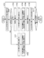
図1は実施例の画像処理装置の構成例を示すブロック図で、画像処理装置21には、画像を表示するカラーモニタ10と画像を記録媒体に印刷するプリンタ20が接続されている。
[Constitution]
FIG. 1 is a block diagram illustrating a configuration example of an image processing apparatus according to an embodiment. A
画像処理装置21は、画像データをビデオ信号に変換するビデオ信号生成部11、画像データを格納するためのメモリ12、モニタ表示色と印刷色をマッチングするカラーマッチング処理部13、目標色データの入力部14、ガマットマッピングにおける写像元の色空間を指定する指定部15、入力および指定された目標色データおよび写像元色空間の情報に基づき後述する色域写像処理に用いる写像制御パラメータを生成するパラメータ生成部16、モニタ10の色再現域からプリンタ20の色再現域への写像を行う色域写像部17、モニタ表示色と印刷色の対応を記憶する色補正テーブル18、並びに、画像データをプリンタ駆動信号に変換する出力画像処理部19を備える。
The
実施例において、処理対象の画像データは、ディジタルカメラ、スキャナなどの画像入力装置によってディジタル化されたデータや、コンピュータグラフィクス(CG)として生成されたデータで、明るさに対応した画素値として画像メモリ12に予め格納されるものとする。具体的には、画像データの各画素はレッド(R)、グリーン(G)、ブルー(B)各8ビット値、合計24ビット値を有するものとする。 In the embodiment, the image data to be processed is data digitized by an image input device such as a digital camera or a scanner, or data generated as computer graphics (CG), and is stored in the image memory as a pixel value corresponding to brightness. 12 is stored in advance. Specifically, each pixel of the image data has a red (R), green (G), and blue (B) 8-bit value, and a total of 24-bit value.
また色補正テーブル18は、プリンタ20の出力特性を考慮した色補正処理を入力RGB値に施すテーブルで、実施例においてはAdobeRGB色空間において規則的に配置された格子点の色座標データと、色補正処理後の色座標データとの対応が格納される。図2は、色補正テーブル18に格納されるデータの一例を示す図で、テーブル先頭には、R/G/B値のステップが示され、続いて色補正データが格納されている。
The color correction table 18 is a table for performing color correction processing on the input RGB values in consideration of the output characteristics of the
さらに、本実施例において目標色データ14は、sRGB色空間において規則的に配置された格子点のそれぞれが、ガマットマッピング後に取るべきL*a*b*値を表したデータとする。
Further, in the present embodiment, the
本実施例において、カラーモニタ10は、AdobeRGBと同等の色再現域をもつCRTまたはLCDなどの表示装置である。また、プリンタ20は、インクジェット方式によるもので、出力記録紙上にシアン(C)、マゼンタ(M)、イエロー(Y)、ブラック(K)のインク滴を吐出し定着して、その密度により色の濃淡を表現するものとする。なお、カラーモニタ10およびプリンタ20としてはこのような形態に限定されず、例えばプリンタ20は電子写真方式や熱転写方式など、他の方式によるものであってもよい。
In this embodiment, the
[動作]
画像処理装置21の画像メモリ12に格納された画像データは、カラーマッチング処理部13に供給される。カラーマッチング処理部13は、ビデオ信号生成部11を経てカラーモニタ10に表示する画像と、出力画像処理部19を経てプリンタ20によって印刷される画像との色マッチングを行う。具体的には、画像データの各画素値に対応する出力値を、色補正テーブル18を参照して補間することで、出力画像処理部19へ供給する画像データを得る。色補正テーブル18のテーブルは、色域写像部17によって、パラメータ生成部16によって生成された写像制御パラメータを参照しながら、モニタ10の色再現域内の複数点をプリンタ20の色再現域へ写像した結果として生成される。
[Operation]
The image data stored in the
色補正された画像データを受け取った出力画像処理部19は、入力RGB画素値に対してCMYKの各インクの吐出を制御する信号をプリンタ20へ供給し、所望の色が記録媒体上に再現される。なお、電子写真方式のような色材としてトナーを用いるプリンタ20の場合、出力画像処理部19は、入力RGB画素値に対してCMYKの感光体ドラムの感光を制御する信号をプリンタ20へ供給する。
Upon receiving the color-corrected image data, the output
[写像制御パラメータの生成]
図3はパラメータ生成部16の構成例を示すブロック図である。
[Mapping control parameter generation]
FIG. 3 is a block diagram illustrating a configuration example of the
パラメータ生成部16は、色域写像部17におけるモニタ色再現域からプリンタ色再現域への写像結果に基づき、写像制御パラメータの値を最適化するパラメータ最適化部30、与えられた写像制御パラメータに対応する評価値を算出する評価部31、評価値に基づき決定される最適な写像制御パラメータを格納するパラメータ記憶部32、指定部15において指定された写像元色空間に基づき、入力部14から入力される目標色データを変換する目標色データ変換部33、並びに、変換後の目標色データを記憶する目標色データ記憶部34を備える。
Based on the mapping result from the monitor color reproduction gamut to the printer color reproduction gamut in the color
図4は指定部15の写像元色空間を指定するユーザインタフェイス(UI)を示す図である。ユーザは、このUI上のラジオボタンによってRGB色空間の一つを選択する。なお、以後、図4に示すように、写像元色空間としてAdobeRGBが選択された場合の処理を説明するが、他のRGB色空間が選択された場合や、UIを使用してその他の色空間が指定された場合も同様である。
FIG. 4 is a diagram showing a user interface (UI) for designating the mapping source color space of the
また、図5は目標色データのフォーマット例を示す図である。目標色データとして、R/G/B値のステップと、RGB値の組み合わせそれぞれに対応するL*a*b*値が記述されている。以下では、目標色データとしてsRGB色空間を示す目標データが入力される場合を説明する。 FIG. 5 is a diagram showing a format example of target color data. As target color data, R / G / B value steps and L * a * b * values corresponding to each combination of RGB values are described. Hereinafter, a case where target data indicating the sRGB color space is input as target color data will be described.
図6はパラメータ生成部16におけるパラメータ生成処理を示すフローチャートである。
FIG. 6 is a flowchart showing parameter generation processing in the
指定部15においてガマットマッピング元になるRGB色空間(写像元色空間)が指定される(S401)。なお、前述したように、ここではAdobeRGBが指定されるとする。入力部14においてsRGB色空間の標本点と、その標本点にに対応するガマットマッピング後のL*a*b*値の対応を記した目標色データ(以下「sRGB目標色データ」と呼ぶ場合がある)の格納先を示すパスが入力されると(S402)、sRGB目標データを入力し、後述する方法によってAdobeRGB色空間における格子点とガマットマッピング後のL*a*b*値の対応を表すAdobeRGB目標色データを生成して、目標色データ記憶部34に格納する(S403)。
An RGB color space (mapping source color space) to be a gamut mapping source is specified by the specifying unit 15 (S401). As described above, it is assumed that AdobeRGB is specified here. Target color data (hereinafter referred to as “sRGB target color data”) that describes the correspondence between the sRGB color space sample points in the
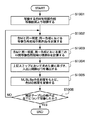
次に、後述する色域写像処理に使用する初期の写像制御パラメータを生成し(S404)、色域写像部17により、写像制御パラメータを用いてモニタ色再現域からプリンタ色再現域への色域写像処理を行う(S405)。この色域写像処理の詳細も後述する。
Next, initial mapping control parameters used for the color gamut mapping process described later are generated (S404), and the color
次に、評価部31により、写像結果に基づき写像制御パラメータの評価値を算出し(S406)、算出した評価値が予め定めた閾値以下であるか否かを判定する(S407)。評価値が閾値を超える場合は、例えば準ニュートン法など公知の最適化手法を用いて、より評価値が小さくなるように写像制御パラメータを更新して(S408)、ステップS405からS407の処理を繰り返す。
Next, the
一方、評価値が閾値以下の場合は、写像制御パラメータをパラメータ記憶部32に格納し(S409)、色域写像処理に必要なすべての写像制御パラメータを生成したか否かを判定し(S410)、未生成の写像制御パラメータが存在する場合は、色域写像処理に必要なすべての写像制御パラメータを生成するまでステップS404からS409の処理を繰り返す。 On the other hand, if the evaluation value is equal to or less than the threshold value, the mapping control parameter is stored in the parameter storage unit 32 (S409), and it is determined whether all the mapping control parameters necessary for the color gamut mapping processing have been generated (S410). If there is an ungenerated mapping control parameter, the processes in steps S404 to S409 are repeated until all mapping control parameters necessary for the color gamut mapping process are generated.
● AdobeRGB目標色データの生成
図7は、目標色データ変換部33が行う、AdobeRGB目標色データの生成処理(S403)を示すフローチャートである。
Generation of AdobeRGB Target Color Data FIG. 7 is a flowchart showing AdobeRGB target color data generation processing (S403) performed by the target color
まず、AdobeRGB色空間に均等に並んだ格子点の一つのRGB値を、計算によってL*a*b*値に変換し(S701)、変換後のL*a*b*値(L*a*b*値で表される格子点)がsRGB色空間の色域(以下「sRGB色域」と呼ぶ)内にあるか否かを判定し(S702)、sRGB色域外にあれば、sRGB色域外の色(L*a*b*値)がsRGB色域の境界上に位置するよう彩度を圧縮する(S703)。 First, one RGB value of grid points evenly arranged in the AdobeRGB color space is converted to an L * a * b * value by calculation (S701), and the converted L * a * b * value (L * a *) It is determined whether or not the grid point (b * value) is within the color gamut of the sRGB color space (hereinafter referred to as “sRGB color gamut”) (S702), and if it is out of the sRGB color gamut, it is out of the sRGB color gamut. The saturation is compressed so that the color (L * a * b * value) is located on the boundary of the sRGB color gamut (S703).
図8は彩度圧縮を説明する模式図で、符号801はL*a*b*色空間におけるAdobeRGB色空間の等色相境界を、符号802はsRGB色空間の等色相境界を、符号803は彩度圧縮前の格子点を、符号804は彩度圧縮後の格子点を表す。図8に示すように、彩度圧縮(S703)は、sRGB色域外の色を等色相、等明度のsRGB色域の境界面に圧縮する。なお、彩度圧縮する前のL*a*b*値、および、AdobeRGB色空間の色域(以下「AdobeRGB色域」と呼ぶ)の境界面の符号805で示すL*a*b*値は、後の処理用に保存しておく。
FIG. 8 is a schematic diagram for explaining saturation compression.
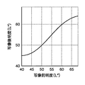
続いて、計算によりL*a*b*値をsRGB値に変換し(S704)、変換後のsRGB値をsRGB目標色データを用いて目標L*a*b*値に変換し(S705)、彩度圧縮前の色と圧縮後の色の関係に基づき、目標L*a*b*値の彩度を伸長する(S706)。図9は彩度伸長を説明する模式図で、符号901はsRGB目標色データが示す色域境界を、符号902はプリンタ20の色再現域を、符号903は彩度伸長前の注目色を、符号904は彩度伸長後の注目色をそれぞれ二次元的に表している。ここで、彩度伸長量は、彩度圧縮量および彩度伸長前の色903とプリンタ20の色再現域902の境界の距離に応じて決定される。
Subsequently, the L * a * b * value is converted into an sRGB value by calculation (S704), the converted sRGB value is converted into a target L * a * b * value using the sRGB target color data (S705), Based on the relationship between the color before saturation compression and the color after compression, the saturation of the target L * a * b * value is expanded (S706). FIG. 9 is a schematic diagram for explaining saturation expansion.
また、変換後のL*a*b*値がsRGB色域内にあれば、ステップS704と同様に、計算によりL*a*b*値からsRGB値へ変換し(S707)、ステップS705と同様に、変換後のsRGB値をsRGB目標色データを用いて目標L*a*b*値に変換する(S708)。 Also, if the converted L * a * b * value is within the sRGB color gamut, it is converted from the L * a * b * value to the sRGB value by calculation (S707) as in step S704, and as in step S705. The converted sRGB values are converted into target L * a * b * values using the sRGB target color data (S708).
そして、AdobeRGB色空間の格子点と、上記処理により得られた目標L*a*b*値との対応を目標色データ記憶部34に保存し(S709)、全格子点の変換処理が終了したか否かを判定し(S710)、未了であればステップS701からS710の処理を全格子点の処理が終了するまで、つまり、AdobeRGB目標色データの生成処理が終了するまで繰り返す。 Then, the correspondence between the grid points of the AdobeRGB color space and the target L * a * b * values obtained by the above processing is stored in the target color data storage unit 34 (S709), and the conversion processing of all grid points is completed. (S710), if not completed, the processing from step S701 to S710 is repeated until the processing of all grid points is completed, that is, until the generation processing of AdobeRGB target color data is completed.
● 色域写像
図10は、色域写像部17が行う、色域写像処理(S405)を示すフローチャートである。
Color Gamut Mapping FIG. 10 is a flowchart showing the color gamut mapping processing (S405) performed by the color
まず、入力部14によってパスが指定されるなどにより、AdobeRGBの色再現域をもつカラーモニタ10の色再現域情報、および、プリンタ20の色再現域情報が設定され(S1001)、これら色再現域情報に基づきカラーモニタ10の色再現域の境界の最終的な写像結果になる写像色再現域の境界を生成する(S1002)。この写像色再現域の境界は、例えば図13に符号1302で示す境界線のようになる。
First, the color gamut information of the color monitor 10 having the AdobeRGB color gamut and the color gamut information of the
次に、均等表色系においてモニタ10の色再現域の明度および色相を写像する(S1003)。本実施例における明度/色相写像動作の詳細は後述するが、図11の明度/色相写像動作を説明する模式図を用いて簡単に説明する。
Next, the brightness and hue of the color gamut of the
図11において、符号1101はグリーンの色相におけるモニタ色再現域を、符号1102は第一の中間写像色再現域を、符号1103は同色相におけるプリンタ色再現域をそれぞれ示している。色域写像部17は、モニタ色再現域1101内の色に対して明度成分と色度成分を分離し、明度成分を非線型に写像する。また、色度成分に対しては、適当になるように色相の調整を行う。これにより、モニタ色再現域1101は第一の中間写像色再現域1102へ写像される。この写像結果から第一の中間写像色再現領域の境界を生成する(S1004)。
In FIG. 11,
続いて、第一の中間写像色再現域1102の境界に対して明度を調整し、第二の中間写像色再現域の境界を生成する(S1005)。図12の明度/色相写像動作を説明する模式図における符号1202は、この色再現域の境界を示している。
Subsequently, the brightness is adjusted with respect to the boundary of the first intermediate mapping
次に、第一の中間写像色再現域(図12に符号1201で示す)の情報を第二の中間写像色再現域(図12に符号1202で示す)へ写像する(S1006)。写像処理の詳細は後述するが、図12の模式図を用いて簡単に説明すると、色域写像部17は、第一の中間写像色再現域1201内の色に対して明度成分と色度成分を分離し、色度成分一定のまま、明度成分のみ非線型に写像する(以下「明度調整写像」と呼ぶ)。なお、写像を実現する明度入出力関数は色度により異なる。この明度調整写像により、第一の中間写像色再現域1201は第二の中間写像色再現域1202に写像される。なお、図12に符号1203で示すのはグリーンの色相におけるプリンタ20の色再現域である。
Next, the information of the first intermediate mapping color reproduction area (indicated by
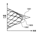
次に、中間写像色再現域の情報と写像色再現域の情報を参照して、第二の中間写像色再現域1202を写像色再現域(図13に符号1302で示す)へ彩度写像する(S1007)。写像処理の詳細は後述するが、図13の明度/色相写像動作を説明する模式図を用いて簡単に説明すると、色域写像部17は、第二の中間写像色再現域1301内の色に対して明度成分と色度成分を分離し、明度成分一定のまま、色度成分における彩度成分を非線型に写像する(以下「彩度調整写像」と呼ぶ)。この彩度調整写像により、第二の中間写像色再現域1301は写像色再現域1302に写像され、図6のステップS405に示す色域写像が終了する。なお、図13に符号1203で示すのはグリーンの色相におけるプリンタ20の色再現域である。
Next, referring to the information on the intermediate mapping color reproduction range and the mapping color reproduction range, the second intermediate mapping
● 明度および色相の写像
次に、明度および色相の写像処理(S1003)について説明する。
● Lightness and Hue Mapping Next, lightness and hue mapping processing (S1003) will be described.
本実施例では、明度成分の写像を、色度に依らない一つの入出力関数を用いて次式により算出する。
Lmapped = λ(Lin) …(1)
In this embodiment, the mapping of the brightness component is calculated by the following equation using one input / output function that does not depend on chromaticity.
L mapped = λ (Lin)… (1)
式(1)の写像関数λ(・)は、パラメータ生成部16において生成される、全体の明度制御パラメータx(写像制御パラメータの一つ)に基づいて、次のように算出される。
x ≧ 50:λ(・) = {λ50(・)×(100 - x) + λ100(・)×(x - 50)}/50
x < 50:λ(・) = {(λ0(・)×(50 - x) + λ50(・)×x}/50
ここで、λ0(・)、λ50(・)、λ100(・)は予め定められた関数で、
λ0(・) はx=0の時の写像関数、
λ50(・)はx=50の時の写像関数、
λ100(・)はx=100の時の写像関数
The mapping function λ (·) of Expression (1) is calculated as follows based on the entire brightness control parameter x (one of the mapping control parameters) generated by the
x ≧ 50: λ (•) = {λ 50 (•) × (100-x) + λ 100 (•) × (x-50)} / 50
x <50: λ (•) = {(λ 0 (•) × (50-x) + λ 50 (•) × x} / 50
Here, λ 0 (·), λ 50 (·), and λ 100 (·) are predetermined functions,
λ 0 (・) is the mapping function when x = 0,
λ 50 (・) is the mapping function when x = 50,
λ 100 (・) is the mapping function when x = 100
図14は色相成分の写像を示すフローチャートである。 FIG. 14 is a flowchart showing mapping of hue components.
まず、パラメータ生成部16において生成される色相制御パラメータ(写像制御パラメータの一つ)に基づき、明度0から100まで20刻みの六つの明度値に対し、色相入出力関数h0(・)、h20(・)、h40(・)、h60(・)、h80(・)およびh100(・)を生成する(S1401)。色相制御パラメータは、レッド(R)、グリーン(G)、ブルー(B)、シアン(C)、マゼンタ(M)およびイエロー(Y)の六色相において、六つの明度値それぞれに対応する色相調整量である。ここで、色相入出力関数は、明度ごとにR/G/B/C/M/Y色相での色相調整値を一次スプライン、すなわち直線で結んだ関数として算出される。一例を示すと、明度値80に対して、RとYの二つの色相において色相角を若干プラスへシフトし、Bの色相でマイナスへシフトした場合には図15に示す色相入出力関数h80(・)が得られる。なお、図15は、色相角を、a*b*色度座標系においてb*軸正方向を色相角0 radとし、反時計方向への回転を正としたラジアン表記により表す。
First, based on the hue control parameter (one of the mapping control parameters) generated by the
次に、写像変換の対象になる色Mを取得し(S1402)、色Mに対する色相入出力関数h(・)を、h0(・)、h20(・)、h40(・)、h60(・)、h80(・)およびh100(・)を用いて、次のように算出する(S1403)。
h(・) = {hLW(・)×(up - x) + hUP(・)×(x - lw)}/20 …(2)
ここで、x:色Mの明度、
hUP(・):明度xの直上の明度UPの入出力関数、
hLW(・):明度xの直下の明度LWの入出力関数
Next, the color M to be mapped is acquired (S1402), and the hue input / output function h (•) for the color M is set to h 0 (•), h 20 (•), h 40 (•), h Using 60 (•), h 80 (•) and h 100 (•), the calculation is performed as follows (S1403).
h (・) = {h LW (・) × (up-x) + h UP (・) × (x-lw)} / 20… (2)
Where x: lightness of color M,
h UP (•): Input / output function of brightness UP just above brightness x,
h LW (•): Input / output function of lightness LW directly below lightness x
例えば、色Mの明度xが70の場合、直下の明度の入出力関数としてh60(・)を、直上の明度の入出力関数としてh80(・)を用いる。従って、明度x=70の色Mに対する色相入出力関数h(・)は次式のようになる。
h(・) = {h60(・) + h80(・)}/2 …(3)
For example, when the lightness x of the color M is 70, h 60 (•) is used as the lightness input / output function immediately below, and h 80 (•) is used as the lightness input / output function immediately above. Therefore, the hue input / output function h (•) for the color M with the lightness x = 70 is as follows.
h (・) = {h 60 (・) + h 80 (・)} / 2… (3)
次に、式(4)を用いて色相の写像を行う(S1404)。
HueMmapped = h(HueM) …(4)
ここで、HueMは色Mの色相、
HueMmappedは写像後の色相
Next, hue mapping is performed using equation (4) (S1404).
Hue M mapped = h (Hue M )… (4)
Where Hue M is the hue of color M,
Hue M mapped is the hue after mapping
そして、先述した明度制御パラメータを用いて明度成分の写像を行い(S1405)、その後、以上のべた明度/色相写像処理がLUTの全格子点ついて行われたか否かを判定し(S1406)、すべての格子点について写像処理が終了するまでステップS1402からS1406を繰り返す。 Then, the brightness component is mapped using the brightness control parameter described above (S1405), and then it is determined whether or not the above brightness / hue mapping processing has been performed for all grid points of the LUT (S1406). Steps S1402 to S1406 are repeated until the mapping process is completed for the grid points.
以上の処理により、図11に示すモニタ色再現域1101は、同図に示す第一の中間写像色再現域1102へ写像される。
Through the above processing, the monitor
● 明度調整写像
図16は明度調整写像(S1006)を説明するフローチャートである。
Brightness Adjustment Map FIG. 16 is a flowchart for explaining the brightness adjustment map (S1006).
まず、写像変換の対象の色Mを指定する(S1601)。なお、この色Mは、第一の中間写像色再現域1102(または1201)における色で、モニタ色再現域1101における色を表すものではない。
First, the color M to be mapped is designated (S1601). The color M is a color in the first intermediate mapping color reproduction region 1102 (or 1201) and does not represent a color in the monitor
次に、色Mと同一の色相における第一の中間写像色再現域1201の上部境界BUおよび下部境界BLを計算し(S1602)、色Mと同一の色相における第二の中間写像色再現域1202の上部境界BUmappedと下部境界BLmappedを算出する(S1603)。
Next, the upper boundary B U and the lower boundary B L of the first intermediate mapped
図17は色M、第一の中間写像色再現域の上部境界BUと下部境界BL、および、第二の中間写像色再現域の上部境界BUmappedと下部境界BLmappedの関係を示す図である。なお、図17において、実線により示される色再現域は第一の中間写像色再現域の境界、一点鎖線により示される色再現域は第二の中間写像色再現域の境界、点線により示される色再現域はプリンタ20の色再現域である。
FIG. 17 shows the relationship between the color M, the upper boundary B U and the lower boundary B L of the first intermediate mapping color reproduction area, and the upper boundary B U mapped and the lower boundary B L mapped of the second intermediate mapping color reproduction area. FIG. In FIG. 17, the color reproduction range indicated by the solid line is the boundary of the first intermediate mapping color reproduction range, and the color reproduction range indicated by the alternate long and short dash line is the boundary of the second intermediate mapping color reproduction range, the color indicated by the dotted line The reproduction area is the color reproduction area of the
続いて、以上で求めた値、および、パラメータ生成部16が生成する写像制御パラメータから明度調整写像を行う入出力関数p(・)を導出する(S1604)。本実施例では、入出力関数p(・)を下記の条件を満たすC2連続な三次スプライン関数として算出する。
・p(・)の台は[LBL, LBU]
・p(・)は台において単調増加
・p(LBL) = LBLm
・p(LBU) = LBUm
・p(・)は少なくともC1連続
・p'(LBL) = g0
・p'(LBU) = g1
ここで、LBLはBLの明度、
LBLmはBLmappedの明度、
LBUはBUの明度、
LBUmはBUmappedの明度、
g0>0、g0は圧縮を制御する変数、
g1>0、g1は圧縮を制御する変数
Subsequently, the input / output function p (•) for performing the brightness adjustment mapping is derived from the value obtained above and the mapping control parameter generated by the parameter generation unit 16 (S1604). In this embodiment, the input / output function p (•) is calculated as a C2 continuous cubic spline function that satisfies the following conditions.
・ The base of p (・) is [LB L , LB U ]
・ P (・) monotonically increases on the stand ・ p (LB L ) = LB Lm
・ P (LB U ) = LB Um
・ P (・) is at least C1 continuous ・ p '(LB L ) = g0
・ P '(LB U ) = g1
Where LB L is the brightness of B L
LB Lm is the brightness of B L mapped,
LB U is the brightness of B U ,
LB Um is the brightness of B U mapped,
g0> 0, g0 is a variable that controls compression,
g1> 0, g1 is a variable that controls compression
上記のg0およびg1の値は、パラメータ生成部16により、評価部31において算出される評価値が最小になるよう算出される。また、入出力関数p(・)は上記条件を満たすよう算出される。
The values of g0 and g1 are calculated by the
図18Aおよび18Bは、本実施例における入出力関数p(・)の例を示す図である。図18Aにおいては、台の中間部において明度がほぼ保たれている一方、低明度付近ならびに高明度付近では大きく圧縮される。ちなみにLBL=40、LBLm=45、LBU=68、LBUm=64である。 18A and 18B are diagrams showing examples of the input / output function p (•) in the present embodiment. In FIG. 18A, the lightness is almost maintained in the middle part of the table, while it is largely compressed near the low lightness and near the high lightness. Incidentally, LB L = 40, LB Lm = 45, LB U = 68, and LB Um = 64.
また、図18Bにおいては明度の変化が大きいため、台の中間部において明度を保存する機能が働いているものの完全には保存していない。高明度付近では大きく伸長され、低明度付近では大きく圧縮される。ちなみにLBL=60、LBLm=46、LBU=84、LBUm=75である。 Further, in FIG. 18B, since the change in brightness is large, the function of saving the brightness works in the middle part of the table, but it is not completely saved. In the vicinity of high lightness, it is greatly expanded, and in the vicinity of low lightness, it is greatly compressed. Incidentally, LB L = 60, LB Lm = 46, LB U = 84, and LB Um = 75.
続いて、ステップS1604で求めた入出力関数p(・)を用いて、色Mの写像前の明度LMに対して写像後の明度LMmappedを、LMmapped=p(LM)と求めて明度調整写像を行う(S1605)。 Subsequently, by using the input / output function p (•) obtained in step S1604, the lightness L M mapped after the mapping of the lightness L M of the color M is expressed as L M mapped = p (L M ) Then, the brightness adjustment mapping is performed (S1605).
そして、明度調整写像が色補正テーブル18の全格子点について行われたか否かを判定し(S1606)、すべての格子点について明度調整写像が終了するまでステップS1602からS1606を繰り返す。 Then, it is determined whether or not the brightness adjustment mapping has been performed for all grid points of the color correction table 18 (S1606), and steps S1602 to S1606 are repeated until the brightness adjustment mapping is completed for all grid points.
以上の処理により、図12に示す第一の中間写像色再現域1201は、同図に示す第二の中間写像色再現域1202へ写像される。
With the above processing, the first intermediate mapped
● 彩度調整写像
図19は彩度調整写像(S1007)を説明するフローチャートである。
Saturation Adjustment Map FIG. 19 is a flowchart for explaining the saturation adjustment map (S1007).
まず、写像計算対象になる色Mを定める(S1901)。この色Mは、第二の中間写像色再現域1202における色である。
First, the color M to be mapped is determined (S1901). The color M is a color in the second intermediate mapping
次に、色Mと同一の明度、同一の色相における写像色再現域の境界Bpを計算し(S1902)、色Mと同一の明度、同一の色相における第二の中間写像色再現域の境界Biを計算する(S1903)。 Next, the boundary Bp of the mapped color reproduction area in the same brightness and the same hue as the color M is calculated (S1902), and the boundary Bi of the second intermediate mapped color reproduction area in the same brightness and the same hue as the color M is calculated. Is calculated (S1903).
図20は色M、色Bp、色Biの関係を模式的に示す図である。図20に実線で示す色再現域は第二の中間写像色再現域の境界、一点鎖線で示す色再現域は写像色再現域の境界、点線で示す色再現域はプリンタ色再現域である。 FIG. 20 is a diagram schematically showing the relationship among the color M, the color Bp, and the color Bi. In FIG. 20, the color gamut indicated by the solid line is the boundary of the second intermediate mapped color gamut, the color gamut indicated by the one-dot chain line is the boundary of the mapped color gamut, and the color gamut indicated by the dotted line is the printer color gamut.
続いて、以上のステップで算出した色Bp、色Biおよびパラメータ生成部16において生成される写像制御パラメータから、彩度調整写像を行うC2連続な三次スプライン関数q(・)を算出する(S1904)。入出力関数q(・)は、本実施例では下記の条件を満たす。
・q(・)の台は[0, ci]
・q(0) = 0
・q(ci) = cp
・q'(0) = gLOW
・q'(ci) = gHIGH
・q'(x) ≠ 0(0 ≦ x ≦ ci)
ここで、cpは色Bpの彩度、
ciは色Biの彩度、
gLOWは低彩度から中彩度付近の彩度の拡大/圧縮率を制御する値、
gHIGHは最大彩度付近の彩度補正の拡大/圧縮率を制御する値
Subsequently, a C2 continuous cubic spline function q (•) for performing saturation adjustment mapping is calculated from the color Bp and color Bi calculated in the above steps and the mapping control parameter generated in the parameter generation unit 16 (S1904). . The input / output function q (•) satisfies the following condition in this embodiment.
・ The base of q (・) is [0, ci]
Q (0) = 0
Q (ci) = cp
Q '(0) = g LOW
Q '(ci) = g HIGH
Q '(x) ≠ 0 (0 ≤ x ≤ ci)
Where cp is the saturation of the color Bp,
ci is the saturation of the color Bi,
g LOW is a value that controls the expansion / compression ratio of saturation from low to medium saturation.
g HIGH is a value that controls the expansion / compression rate of saturation correction near the maximum saturation.
上記のgLOW、gHIGHの値は、パラメータ生成部16により、評価部31で算出される評価値が最小になるよう導出される。
The values of g LOW and g HIGH are derived by the
図21Aおよび21Bは、本実施例における入出力関数q(・)の一例を示す図である。図21Aにおいては、高彩度部で伸長になる一方、gLOWの値が0.8であるために低彩度から中彩度部では彩度を抑えるように機能する。図21Bは、高彩度部で圧縮になり、gLOWの値が1.2であるために低彩度から中彩度部では彩度を強調するように機能する。 21A and 21B are diagrams illustrating an example of the input / output function q (•) in the present embodiment. In FIG. 21A, while the expansion is performed in the high saturation part, the value of g LOW is 0.8, so that the function is performed to suppress the saturation in the low saturation to the intermediate saturation part. In FIG. 21B, compression is performed in the high saturation portion, and since the value of g LOW is 1.2, the saturation is enhanced in the low saturation to medium saturation portions.
続いて、ステップS1904で求めた入出力関数q(・)を用いて、色Mの彩度を変換する(S1905)。ここで色Cの彩度をCorg、変換後の彩度をCmodと表記するとCmod=q(Corg)になる。 Subsequently, the saturation of the color M is converted using the input / output function q (•) obtained in step S1904 (S1905). Here, if the saturation of the color C is expressed as Corg and the converted saturation is expressed as Cmod, Cmod = q (Corg).
最後に、彩度調整写像が色補正テーブル18の全格子点について行われたか否かを判定し(S1906)、すべての格子点について彩度調整写像が終了するまでステップS1901からS1906を繰り返す。 Finally, it is determined whether or not the saturation adjustment mapping has been performed for all grid points in the color correction table 18 (S1906), and steps S1901 to S1906 are repeated until the saturation adjustment mapping is completed for all grid points.
以上の処理により、図13に示す第二の中間色再現域1301は、同図に示す写像色再現域1302へ写像される。
Through the above processing, the second intermediate
[評価値の算出]
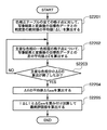
図22は写像結果の評価値の算出(S406)を説明するフローチャートである。
[Calculation of evaluation value]
FIG. 22 is a flowchart for explaining the calculation of the evaluation value of the mapping result (S406).
まず、色補正テーブル18の格子点すべてに対して、色域写像部17で写像された結果と、目標データ記憶部34に記憶された変換後の目標色データとの明度差の絶対値|ΔL|を算出し、その平均値を求め(S2201)、RGBCMYのうちの一色相について、当該色相の面上に位置する複数格子点の写像結果と、対応する変換後の目標色データとの差の平均値ΔEを求める(S2202)。その後、RGBCMYの六色相について平均値ΔEの算出が完了したか否かを判定し(S2203)、六色相について平均値ΔEを算出するまでステップS2202を繰り返す。
First, for all grid points of the color correction table 18, the absolute value of the brightness difference between the result mapped by the
六色相の平均値ΔEの算出が終了すると、算出した六色相分のΔEの平均値ΔEaveを算出し(S2204)、式(5)により最終的な評価値evalを算出する(S2205)。
eval = α×|ΔL| + β×ΔEave
ここで、α、βは重み付け係数、α≧0、β≦1
When the calculation of the average value ΔE of the six hues is completed, the average value ΔEave of ΔE for the calculated six hues is calculated (S2204), and the final evaluation value eval is calculated by the equation (5) (S2205).
eval = α × | ΔL | + β × ΔEave
Where α and β are weighting factors, α ≧ 0, β ≦ 1
以上の処理により、一組の写像制御パラメータに対する評価値の算出処理を終了する。 With the above processing, the evaluation value calculation processing for a set of mapping control parameters is completed.
このように、本実施例によれば、sRGBなどを写像元とするガマットマッピング後の目標色データを与えるだけで、AdobeRGBなどの拡張色空間を写像元とするガマットマッピングを制御する写像制御パラメータを自動生成することが可能になる。 As described above, according to this embodiment, the mapping control parameter for controlling the gamut mapping using the extended color space such as AdobeRGB as the mapping source only by giving the target color data after the gamut mapping using sRGB or the like as the mapping source. It can be automatically generated.
[変形例]
上記においては、sRGB色域外の色について彩度圧縮を行い、sRGB目標データを用いてプリンタ色再現域内の色に写像した後、彩度伸長を行うことで、AdobeRGB目標データを生成したが、sRGB色域外の色については、これ以外の処理を行っても構わない。例えば、L*a*b*表色系においてsRGB色域表面の最も距離が近い点に圧縮してもよい。
[Modification]
In the above, saturation compression is performed for colors outside the sRGB color gamut, mapping to colors within the printer color gamut using the sRGB target data, and then decompressing the saturation to generate AdobeRGB target data. For colors outside the color gamut, other processes may be performed. For example, in the L * a * b * color system, the sRGB color gamut surface may be compressed to the closest point.
上記においては、目標色データとのΔL、ΔEを用いて写像結果の評価値を算出したが、他の評価方法を用いても構わない。 In the above, the evaluation value of the mapping result is calculated using ΔL and ΔE with the target color data, but other evaluation methods may be used.
上記においては、全色領域において目標色との明度差、主要な六色相において色差ΔEを算出したが、異なる色領域に対して評価を行ってもよい。例えば、肌色等の低彩度部を重視するため、低彩度から中彩度部について目標色との差を評価するなどの手法を用いても構わない。 In the above description, the brightness difference from the target color in all the color regions and the color difference ΔE in the main six hues are calculated. However, different color regions may be evaluated. For example, in order to place importance on the low saturation portion such as skin color, a method of evaluating the difference from the target color in the low saturation to the intermediate saturation portion may be used.
[他の実施例]
なお、本発明は、複数の機器(例えばホストコンピュータ、インタフェイス機器、リーダ、プリンタなど)から構成されるシステムに適用しても、一つの機器からなる装置(例えば、複写機、ファクシミリ装置など)に適用してもよい。
[Other embodiments]
Note that the present invention can be applied to a system including a plurality of devices (for example, a host computer, an interface device, a reader, and a printer), and a device (for example, a copying machine and a facsimile device) including a single device. You may apply to.
また、本発明の目的は、前述した実施例の機能を実現するソフトウェアのプログラムコードを記録した記憶媒体(または記録媒体)を、システムあるいは装置に供給し、そのシステムあるいは装置のコンピュータ(またはCPUやMPU)が記憶媒体に格納されたプログラムコードを読み出し実行することによっても、達成されることは言うまでもない。この場合、記憶媒体から読み出されたプログラムコード自体が前述した実施例の機能を実現することになり、そのプログラムコードを記憶した記憶媒体は本発明を構成することになる。また、コンピュータが読み出したプログラムコードを実行することにより、前述した実施例の機能が実現されるだけでなく、そのプログラムコードの指示に基づき、コンピュータ上で稼働しているオペレーティングシステム(OS)などが実際の処理の一部または全部を行い、その処理によって前述した実施例の機能が実現される場合も含まれることは言うまでもない。 Also, an object of the present invention is to supply a storage medium (or recording medium) on which a program code of software that realizes the functions of the above-described embodiments is recorded to a system or apparatus, and the computer (or CPU or CPU) of the system or apparatus. Needless to say, this can also be achieved by the MPU) reading and executing the program code stored in the storage medium. In this case, the program code itself read from the storage medium realizes the functions of the above-described embodiments, and the storage medium storing the program code constitutes the present invention. Further, by executing the program code read by the computer, not only the functions of the above-described embodiments are realized, but also an operating system (OS) running on the computer based on the instruction of the program code. It goes without saying that a case where the function of the above-described embodiment is realized by performing part or all of the actual processing and the processing is included.
さらに、記憶媒体から読み出されたプログラムコードが、コンピュータに挿入された機能拡張カードやコンピュータに接続された機能拡張ユニットに備わるメモリに書込まれた後、そのプログラムコードの指示に基づき、その機能拡張カードや機能拡張ユニットに備わるCPUなどが実際の処理の一部または全部を行い、その処理によって前述した実施例の機能が実現される場合も含まれることは言うまでもない。 Furthermore, after the program code read from the storage medium is written into a memory provided in a function expansion card inserted into the computer or a function expansion unit connected to the computer, the function is determined based on the instruction of the program code. Needless to say, the CPU of the expansion card or the function expansion unit performs part or all of the actual processing and the functions of the above-described embodiments are realized by the processing.
本発明を上記記憶媒体に適用する場合、その記憶媒体には、先に説明したフローチャートに対応するプログラムコードが格納されることになる。 When the present invention is applied to the storage medium, the storage medium stores program codes corresponding to the flowcharts described above.
Claims (11)
前記第一および第二の色再現域とは異なる第三の色再現域内の複数の標本点、および、前記標本点に対応する写像後の色を示す情報を目標色データとして入力し、
写像された複数色と前記目標色データに基づき評価値を算出し、
前記目標色データおよび前記評価値に基づき前記制御パラメータを設定することを特徴とする色変換方法。 A color conversion method for mapping a color in a first color gamut to a color in a second color gamut different from the first color gamut based on a control parameter,
A plurality of sample points in a third color gamut different from the first and second color gamuts, and input information indicating the color after mapping corresponding to the sample points as target color data,
An evaluation value is calculated based on the mapped multiple colors and the target color data,
A color conversion method, wherein the control parameter is set based on the target color data and the evaluation value.
前記第一および第二の色再現域とは異なる第三の色再現域内の複数の標本点、および、前記標本点に対応する写像後の色を示す情報を目標色データとして入力する入力手段と、
前記写像手段により写像された複数色と前記目標色データに基づき、評価値を算出する評価手段と、
前記目標色データおよび前記評価値に基づき、前記制御パラメータを設定する設定手段とを有することを特徴とする色変換装置。 Mapping means capable of controlling the mapping by a control parameter for mapping a color in the first color gamut to a color in a second color gamut different from the first color gamut;
A plurality of sample points in a third color gamut different from the first and second color gamuts, and input means for inputting information indicating the color after mapping corresponding to the sample points as target color data; ,
Evaluation means for calculating an evaluation value based on the plurality of colors mapped by the mapping means and the target color data;
A color conversion apparatus comprising: setting means for setting the control parameter based on the target color data and the evaluation value.
Priority Applications (1)
| Application Number | Priority Date | Filing Date | Title |
|---|---|---|---|
| JP2004106356A JP2005295153A (en) | 2004-03-31 | 2004-03-31 | Color conversion device and its method |
Applications Claiming Priority (1)
| Application Number | Priority Date | Filing Date | Title |
|---|---|---|---|
| JP2004106356A JP2005295153A (en) | 2004-03-31 | 2004-03-31 | Color conversion device and its method |
Publications (1)
| Publication Number | Publication Date |
|---|---|
| JP2005295153A true JP2005295153A (en) | 2005-10-20 |
Family
ID=35327609
Family Applications (1)
| Application Number | Title | Priority Date | Filing Date |
|---|---|---|---|
| JP2004106356A Withdrawn JP2005295153A (en) | 2004-03-31 | 2004-03-31 | Color conversion device and its method |
Country Status (1)
| Country | Link |
|---|---|
| JP (1) | JP2005295153A (en) |
Cited By (11)
| Publication number | Priority date | Publication date | Assignee | Title |
|---|---|---|---|---|
| JP2008118590A (en) * | 2006-11-08 | 2008-05-22 | Fuji Xerox Co Ltd | Image processor and image processing program |
| KR100834766B1 (en) | 2007-01-24 | 2008-06-05 | 삼성전자주식회사 | Color management apparatus and method for the same |
| JP2008141723A (en) * | 2006-11-09 | 2008-06-19 | Seiko Epson Corp | Image processing apparatus, image processing method, image processing program, recording medium recording image processing program, and image display apparatus |
| KR100843088B1 (en) | 2006-08-16 | 2008-07-02 | 삼성전자주식회사 | Apparatus and method for outputting wide color gamut space image |
| JP2008289092A (en) * | 2007-05-21 | 2008-11-27 | Canon Inc | Color signal conversion method and color signal conversion apparatus |
| US7864371B2 (en) | 2007-03-07 | 2011-01-04 | Ricoh Company, Ltd. | Image processing apparatus, image processing method, and computer product |
| CN101184148B (en) * | 2006-11-13 | 2011-01-26 | 富士施乐株式会社 | Color processing device and method |
| US8237986B2 (en) | 2007-12-21 | 2012-08-07 | Canon Kabushiki Kaisha | Image reading apparatus, multifunction printer apparatus, and image processing method |
| US8243351B2 (en) | 2007-12-21 | 2012-08-14 | Canon Kabushiki Kaisha | Image reading apparatus, multifunction printer apparatus, and image processing method |
| US8294955B2 (en) | 2007-12-21 | 2012-10-23 | Canon Kabushiki Kaisha | Image reading apparatus, multifunction printer apparatus, and image processing method |
| CN113613007A (en) * | 2021-07-19 | 2021-11-05 | 青岛信芯微电子科技股份有限公司 | Three-dimensional color lookup table generation method and display device |
-
2004
- 2004-03-31 JP JP2004106356A patent/JP2005295153A/en not_active Withdrawn
Cited By (12)
| Publication number | Priority date | Publication date | Assignee | Title |
|---|---|---|---|---|
| KR100843088B1 (en) | 2006-08-16 | 2008-07-02 | 삼성전자주식회사 | Apparatus and method for outputting wide color gamut space image |
| JP2008118590A (en) * | 2006-11-08 | 2008-05-22 | Fuji Xerox Co Ltd | Image processor and image processing program |
| JP2008141723A (en) * | 2006-11-09 | 2008-06-19 | Seiko Epson Corp | Image processing apparatus, image processing method, image processing program, recording medium recording image processing program, and image display apparatus |
| CN101184148B (en) * | 2006-11-13 | 2011-01-26 | 富士施乐株式会社 | Color processing device and method |
| KR100834766B1 (en) | 2007-01-24 | 2008-06-05 | 삼성전자주식회사 | Color management apparatus and method for the same |
| US7864371B2 (en) | 2007-03-07 | 2011-01-04 | Ricoh Company, Ltd. | Image processing apparatus, image processing method, and computer product |
| JP2008289092A (en) * | 2007-05-21 | 2008-11-27 | Canon Inc | Color signal conversion method and color signal conversion apparatus |
| US8237986B2 (en) | 2007-12-21 | 2012-08-07 | Canon Kabushiki Kaisha | Image reading apparatus, multifunction printer apparatus, and image processing method |
| US8243351B2 (en) | 2007-12-21 | 2012-08-14 | Canon Kabushiki Kaisha | Image reading apparatus, multifunction printer apparatus, and image processing method |
| US8294955B2 (en) | 2007-12-21 | 2012-10-23 | Canon Kabushiki Kaisha | Image reading apparatus, multifunction printer apparatus, and image processing method |
| CN113613007A (en) * | 2021-07-19 | 2021-11-05 | 青岛信芯微电子科技股份有限公司 | Three-dimensional color lookup table generation method and display device |
| CN113613007B (en) * | 2021-07-19 | 2024-03-05 | 青岛信芯微电子科技股份有限公司 | Three-dimensional color lookup table generation method and display device |
Similar Documents
| Publication | Publication Date | Title |
|---|---|---|
| US6922266B2 (en) | Color management system | |
| JP4623630B2 (en) | Image processing apparatus, image processing method, program, image forming apparatus, and image forming system | |
| US20070030499A1 (en) | Color processing method and apparatus | |
| US20050280848A1 (en) | Color conversion method, color conversion device, printing control device, and program recording medium | |
| EP1589746A2 (en) | System and method for gamut mapping control | |
| JP2008028679A (en) | Color conversion table, and method and device for generating the same | |
| JP2005253072A5 (en) | ||
| JP2007043424A (en) | Color processing method and apparatus adopting the same | |
| US20040126009A1 (en) | Image processing apparatus, image processing method, and image processing program | |
| JP5777497B2 (en) | Color processing apparatus and method | |
| JP2005295153A (en) | Color conversion device and its method | |
| JP2007028148A (en) | Apparatus, method and program for color conversion, and recording medium | |
| JP2004058622A (en) | Image processing method and image processor | |
| JP2008147937A (en) | Image processor and image processing method | |
| JP6155644B2 (en) | Image processing apparatus, image processing method, program, and storage medium | |
| JP4137393B2 (en) | Image processing apparatus, image processing method, color conversion table creation method, and recording medium | |
| JP2004058624A (en) | Image processing method and image processor | |
| JP2020203454A (en) | Image processing device and image forming device | |
| JP5159565B2 (en) | Color processing apparatus and method | |
| JP2003334934A (en) | Device and method for controlling forming of image, and image forming control program | |
| JP2009218780A (en) | Image processing method, printer, color conversion device, and color conversion program | |
| JP4023417B2 (en) | Image processing using LUT | |
| JP5595341B2 (en) | Image processing apparatus, image processing method, and recording apparatus | |
| JP2009017473A (en) | Color gamut generation device, color gamut generation method, color gamut generation program, and color conversion unit | |
| JP4227371B2 (en) | Image processing apparatus and method |
Legal Events
| Date | Code | Title | Description |
|---|---|---|---|
| A300 | Withdrawal of application because of no request for examination |
Free format text: JAPANESE INTERMEDIATE CODE: A300 Effective date: 20070605 |