JP4390582B2 - Electronic stylus and method for determining position of tip of stylus - Google Patents
Electronic stylus and method for determining position of tip of stylus Download PDFInfo
- Publication number
- JP4390582B2 JP4390582B2 JP2004038977A JP2004038977A JP4390582B2 JP 4390582 B2 JP4390582 B2 JP 4390582B2 JP 2004038977 A JP2004038977 A JP 2004038977A JP 2004038977 A JP2004038977 A JP 2004038977A JP 4390582 B2 JP4390582 B2 JP 4390582B2
- Authority
- JP
- Japan
- Prior art keywords
- ultrasonic
- transmitter
- receiver
- stylus
- signal
- Prior art date
- Legal status (The legal status is an assumption and is not a legal conclusion. Google has not performed a legal analysis and makes no representation as to the accuracy of the status listed.)
- Expired - Fee Related
Links
Images


Classifications
-
- B—PERFORMING OPERATIONS; TRANSPORTING
- B66—HOISTING; LIFTING; HAULING
- B66F—HOISTING, LIFTING, HAULING OR PUSHING, NOT OTHERWISE PROVIDED FOR, e.g. DEVICES WHICH APPLY A LIFTING OR PUSHING FORCE DIRECTLY TO THE SURFACE OF A LOAD
- B66F17/00—Safety devices, e.g. for limiting or indicating lifting force
-
- G—PHYSICS
- G06—COMPUTING; CALCULATING OR COUNTING
- G06F—ELECTRIC DIGITAL DATA PROCESSING
- G06F3/00—Input arrangements for transferring data to be processed into a form capable of being handled by the computer; Output arrangements for transferring data from processing unit to output unit, e.g. interface arrangements
- G06F3/01—Input arrangements or combined input and output arrangements for interaction between user and computer
- G06F3/03—Arrangements for converting the position or the displacement of a member into a coded form
- G06F3/041—Digitisers, e.g. for touch screens or touch pads, characterised by the transducing means
- G06F3/043—Digitisers, e.g. for touch screens or touch pads, characterised by the transducing means using propagating acoustic waves
-
- G—PHYSICS
- G06—COMPUTING; CALCULATING OR COUNTING
- G06F—ELECTRIC DIGITAL DATA PROCESSING
- G06F3/00—Input arrangements for transferring data to be processed into a form capable of being handled by the computer; Output arrangements for transferring data from processing unit to output unit, e.g. interface arrangements
- G06F3/01—Input arrangements or combined input and output arrangements for interaction between user and computer
- G06F3/03—Arrangements for converting the position or the displacement of a member into a coded form
- G06F3/033—Pointing devices displaced or positioned by the user, e.g. mice, trackballs, pens or joysticks; Accessories therefor
- G06F3/0354—Pointing devices displaced or positioned by the user, e.g. mice, trackballs, pens or joysticks; Accessories therefor with detection of 2D relative movements between the device, or an operating part thereof, and a plane or surface, e.g. 2D mice, trackballs, pens or pucks
- G06F3/03545—Pens or stylus
-
- E—FIXED CONSTRUCTIONS
- E04—BUILDING
- E04H—BUILDINGS OR LIKE STRUCTURES FOR PARTICULAR PURPOSES; SWIMMING OR SPLASH BATHS OR POOLS; MASTS; FENCING; TENTS OR CANOPIES, IN GENERAL
- E04H6/00—Buildings for parking cars, rolling-stock, aircraft, vessels or like vehicles, e.g. garages
- E04H6/42—Devices or arrangements peculiar to garages, not covered elsewhere, e.g. securing devices, safety devices, monitoring and operating schemes; centering devices
Landscapes
- Engineering & Computer Science (AREA)
- General Engineering & Computer Science (AREA)
- Theoretical Computer Science (AREA)
- Physics & Mathematics (AREA)
- Human Computer Interaction (AREA)
- General Physics & Mathematics (AREA)
- Acoustics & Sound (AREA)
- Geology (AREA)
- Life Sciences & Earth Sciences (AREA)
- Mechanical Engineering (AREA)
- Structural Engineering (AREA)
- Length Measuring Devices Characterised By Use Of Acoustic Means (AREA)
- Position Input By Displaying (AREA)
- Measurement Of Velocity Or Position Using Acoustic Or Ultrasonic Waves (AREA)
- Drawing Aids And Blackboards (AREA)
- Arrangements For Transmission Of Measured Signals (AREA)
- Ultra Sonic Daignosis Equipment (AREA)
Description
本発明は、電子スタイラス及びスタイラスの先端の位置を判定する方法に関し、より詳細には、電子スタイラスの使用中に電子スタイラスの先端の位置を正確に突き止めて記録するための、電子スタイラス及び電子スタイラスシステム並びにスタイラスの先端の位置を判定する方法に関する。 The present invention relates to an electronic stylus and a method for determining the position of a stylus tip, and more particularly to an electronic stylus and an electronic stylus for accurately locating and recording the tip position of an electronic stylus during use of the electronic stylus. The present invention relates to a system and a method for determining the position of the tip of a stylus.
ラップトップコンピュータは、デスクトップコンピュータが利用不可能であるか実用的ではない場所で移動または仕事をしなければならない人々が使用するためのものとして、ますます普及しつつある。今日のラップトップは、多くのデスクトップと同じほど強力かつ機能豊富であることが多い。例えば、今や多くのラップトップには、大型の表示装置およびフルサイズのキーボードが装備されるようになっている。ラップトップコンピュータは、適切な状況では非常に有用だが、離れた場所やスペースの限られた場所で使用するには大きすぎ、かつ/または重すぎることが多い。さらに、ラップトップコンピュータの電池寿命は通常は約2〜4時間にすぎず、このことがリモート位置でのラップトップコンピュータの有用性をさらに制限している。最後に、データ入力しか必要とされない状況では、ラップトップコンピュータでは単に行き過ぎである場合がある。 Laptop computers are becoming increasingly popular for use by people who have to move or work where desktop computers are not available or practical. Laptops today are often as powerful and feature rich as many desktops. For example, many laptops are now equipped with large display devices and full-size keyboards. Laptop computers are very useful in appropriate situations, but are often too large and / or too heavy for use in remote locations or spaces. Furthermore, the battery life of laptop computers is typically only about 2-4 hours, which further limits the usefulness of laptop computers at remote locations. Finally, in situations where only data entry is required, a laptop computer may simply go too far.
移動データ入力のためのラップトップコンピュータに対する代替の1つは、携帯情報端末(PDA)である。データ入力にコンピュータキーボードを使用するラップトップとは異なり、PDAでは一般にスタイラスを採用し、スタイラスを使用してPDAの画面上に筆記する。次いで筆記は取り込まれ、PDA中の手書き認識ソフトウェアを使用して処理される。残念ながら、ほとんどのPDAの画面は比較的小さく、したがって、一度に入力および閲覧できるテキストまたはデータの量は限られている。さらに、多くのPDAでは、ユーザが手書きテキストを入力する際に特別な文字体系を学習して利用する必要がある。 One alternative to a laptop computer for mobile data entry is a personal digital assistant (PDA). Unlike laptops that use computer keyboards for data entry, PDAs typically employ a stylus and write on the PDA screen using the stylus. The writing is then captured and processed using handwriting recognition software in the PDA. Unfortunately, most PDA screens are relatively small, and therefore the amount of text or data that can be entered and viewed at one time is limited. Furthermore, in many PDAs, it is necessary to learn and use a special character system when a user inputs handwritten text.
移動データ入力のためのラップトップとPDAの両方に対する最近の代替は、いわゆるペンベースのテキスト入力システム、すなわちデジタルペンである。デジタルペンは通常、ユーザが一綴りの紙の上に筆記または描画することを可能にし、この筆記または描画をペン内のメモリに、またはPDAなど付属デバイス内のメモリに取り込む。この場合、筆記または描画は、後で手書き認識などの処理のために従来型のコンピュータに転送することができる。 A recent alternative to both laptops and PDAs for mobile data entry is the so-called pen-based text entry system, ie the digital pen. Digital pens typically allow a user to write or draw on a single piece of paper and capture this writing or drawing in memory in the pen or in a memory in an attached device such as a PDA. In this case, the writing or drawing can later be transferred to a conventional computer for processing such as handwriting recognition.
デジタルペンがテキストまたは筆記を取り込む方法にはいくつかある。このような方法の1つは、ペン内に位置する小さなカメラを使用して、テキストまたはデータが筆記されているときにそれらを取り込むものである。これらの「カメラベース」のペンでは、一連の微小なドットが紙全体に間隔を空けて配置された特殊用紙を使用する必要がある。ユーザが紙の上にペンで筆記するのに伴って、ペンの先端付近にある小さなカメラがドットパターンの画像を取り込む。次いで、ペン内のプロセッサが、取り込まれた画像を使用して、画像が取り込まれた瞬間にペンの点がページ上のどこにあったかを数学的に判定する。画像から画像へのドットパターンの変化を調べることにより、ペンは、ペン先端があった位置の仮想軌跡を生み出す。このデータから、ペンが紙全体にわたって取った経路の記録を生成することができる。 There are several ways a digital pen can capture text or writing. One such method is to use a small camera located in the pen to capture text or data as it is being written. These “camera-based” pens require the use of special paper in which a series of small dots are spaced across the paper. As the user writes with a pen on paper, a small camera near the tip of the pen captures a dot pattern image. The processor in the pen then uses the captured image to mathematically determine where the pen point was on the page at the moment the image was captured. By examining the change in the dot pattern from image to image, the pen creates a virtual trajectory of where the pen tip was. From this data, a record of the path taken by the pen across the paper can be generated.
残念ながら、これらの「カメラベース」のデジタルペンには、いくつかの欠点がある。これらの欠点のうちで最も顕著なものは、ペンが機能するために特殊な「ドット付き」用紙を使用しなければならないことである。この特殊用紙は、標準的な紙よりも高価である。さらに、この特殊用紙はしばしば入手困難である。したがって、カメラベースのデジタルペンを実際的に使用するには、この特殊用紙を常に携帯していなければならない。 Unfortunately, these “camera-based” digital pens have several drawbacks. The most prominent of these drawbacks is that special “dotted” paper must be used for the pen to function. This special paper is more expensive than standard paper. Furthermore, this special paper is often difficult to obtain. Therefore, in order to actually use a camera-based digital pen, this special paper must always be carried.
これらのカメラベースのデジタルペンに対する代替の1つは、超音波タイプのデジタルペンである。現在の超音波タイプのデジタルペンは、単一の超音波送信機をペン内で使用し、この超音波送信機は、通常は一綴りの紙に留められているか取り付けられている超音波受信機ユニットに、超音波信号を送信する。超音波受信機ユニットは通常、ペンから送信された信号を受信するための2つの超音波受信機を備える。単純な二次元の三角測量技法を用いて、1枚の紙などの二次元平面上におけるペン先端の位置を判定することができる。 One alternative to these camera-based digital pens is an ultrasound type digital pen. Current ultrasonic type digital pens use a single ultrasonic transmitter within the pen, which is usually an ultrasonic receiver that is fastened or attached to a single sheet of paper. An ultrasonic signal is transmitted to the unit. The ultrasound receiver unit typically comprises two ultrasound receivers for receiving signals transmitted from the pen. A simple two-dimensional triangulation technique can be used to determine the position of the pen tip on a two-dimensional plane such as a piece of paper.
残念ながら、これらの超音波タイプのデジタルペンは、筆記中および描画中のペン先端の正確な位置を判定する際にあまり精度がよくない。このように精度を欠く主な理由は、ペン内の超音波送信機の位置に関係がある。超音波送信機のサイズおよびペンの寸法のため、超音波送信機は、ペン先端からいくらか離れた位置になければならない。このことは、ペンが紙に対して完全に垂直の向きに保持されているときは問題ではない。このように保持されていれば、送信機は、ペン先端の上で一直線に整列し、したがって二次元平面でペン先端と同じ位置に整列する。しかし、ペンが傾いているときは、送信機はもはやペン先端の上で一直線に整列しない。それどころか送信機は、二次元空間でペン先端からいくらか離れた位置にあることになる。受信機はペン先端の位置ではなく送信機の位置を記録するので、ペンが傾いているときには不正確な先端位置が記録されることになるが、ペンの傾きは筆記中に必然的に生じる。 Unfortunately, these ultrasonic type digital pens are not very accurate in determining the exact position of the pen tip during writing and drawing. The main reason for the lack of accuracy is related to the position of the ultrasonic transmitter in the pen. Due to the size of the ultrasound transmitter and the dimensions of the pen, the ultrasound transmitter must be at some distance from the pen tip. This is not a problem when the pen is held in a completely perpendicular orientation with respect to the paper. When held in this way, the transmitter is aligned in a straight line on the pen tip, and thus in the same position as the pen tip in a two-dimensional plane. However, when the pen is tilted, the transmitter no longer aligns on the pen tip. On the contrary, the transmitter is located some distance from the pen tip in two-dimensional space. Since the receiver records the position of the transmitter rather than the position of the pen tip, an incorrect tip position will be recorded when the pen is tilted, but pen tilt will inevitably occur during writing.
尚、出願人が知っている先行技術として、記載すべき先行技術文献情報は特に見あたらない。 Note that there is no particular prior art document information to be described as prior art known to the applicant.
したがって、ペンベースの移動データ取込みシステムであって、送信機の位置ではなくペン先端の位置を正確に記録し、特殊用紙を使用する必要のないシステムが必要とされている。 Accordingly, there is a need for a pen-based movement data capture system that accurately records the position of the pen tip rather than the position of the transmitter and does not require the use of special paper.
本発明は、このような状況に鑑みてなされたもので、その目的とするところは、正確な電子スタイラスの先端位置の判定を可能とする、電子スタイラス及びスタイラスの先端の位置を判定する方法を提供することにある。 The present invention has been made in view of such circumstances, and an object of the present invention is to provide an electronic stylus and a method for determining the position of the tip of the stylus that enables accurate determination of the tip position of the electronic stylus. It is to provide.
本明細書に、電子スタイラスの先端位置を正確に判定するための様々なシステムおよび方法の実施形態について述べる。一実施形態によれば、電子スタイラスシステムが、電子スタイラスおよびベース受信ユニットを備える。電子スタイラスは、複数の超音波送信機と、電磁送信機と、筆記先端とを備える。ベース受信機ユニットは、複数の超音波受信機と、電磁受信機とを備える。ベースユニットの超音波受信機は、電子スタイラスの超音波送信機から送信された信号を受信するように動作可能である。同様に、ベースユニットの電磁受信機は、スタイラスの電磁送信機から送信された信号を受信するように動作可能である。 Described herein are various system and method embodiments for accurately determining the tip position of an electronic stylus. According to one embodiment, an electronic stylus system comprises an electronic stylus and a base receiving unit. The electronic stylus includes a plurality of ultrasonic transmitters, an electromagnetic transmitter, and a writing tip. The base receiver unit includes a plurality of ultrasonic receivers and an electromagnetic receiver. The base unit ultrasonic receiver is operable to receive signals transmitted from the electronic stylus ultrasonic transmitter. Similarly, the base unit electromagnetic receiver is operable to receive signals transmitted from the stylus electromagnetic transmitter.
別の実施形態は、所与の基準点に対する電子スタイラスの先端位置を突き止める方法に関する。この実施形態によれば、まず、所与の基準点に対して、電子スタイラス内の2つの超音波送信機の位置を判定する。次いで、判定した2つの超音波送信機の位置と電子スタイラスの様々な幾何形状とを使用して、所与の基準点に対する電子スタイラスの先端位置を判定する。 Another embodiment relates to a method for locating the tip position of an electronic stylus relative to a given reference point. According to this embodiment, the positions of the two ultrasonic transmitters in the electronic stylus are first determined with respect to a given reference point. The determined position of the two ultrasonic transmitters and various electronic stylus geometries are then used to determine the tip position of the electronic stylus relative to a given reference point.
以上説明したように本発明によれば、ペンベースの移動データ取込みシステムにおいて、送信機の位置ではなくペン先端の位置を正確に記録できる。 As described above, according to the present invention, in the pen-based movement data capturing system, it is possible to accurately record the position of the pen tip instead of the position of the transmitter.
以下、図面を参照して本発明を適用できる実施形態を詳細に説明する。理解しやすくするため、各図に共通の同一要素を示すのには同一の参照番号を可能な限り使用している。 Embodiments to which the present invention can be applied will be described below in detail with reference to the drawings. To facilitate understanding, identical reference numerals have been used, where possible, to designate identical elements that are common to the figures.
以下の記述では、添付の特許請求の範囲に詳述する要素を組み込んだ電子スタイラスシステムおよび方法の具体的な実施形態について述べる。法定要件を満たすため、実施形態は詳細に述べる。ただし、この記述自体は、本特許の範囲を限定するものではない。そうではなく、特許請求する本発明を他の方式で実施して、この文書に述べる要素に類似する異なる要素または要素の組合せを他の現在または将来の技術と共に含めることもできると企図している。 The following description sets forth specific embodiments of electronic stylus systems and methods that incorporate the elements detailed in the appended claims. In order to meet statutory requirements, embodiments are described in detail. However, this description itself does not limit the scope of this patent. Rather, it is contemplated that the claimed invention may be implemented in other ways to include different elements or combinations of elements similar to those described in this document, along with other current or future technologies. .
一般に、述べられている実施形態は、従来の筆記用紙などの上でスタイラスを使用して筆記または描画が行われている間に、スタイラスの先端の位置を正確に取り込んで記録するためのシステムおよび方法に関する。本明細書に述べる様々な実施形態によれば、本明細書で電子スタイラスと呼ぶスタイラスは、少なくとも2つの超音波送信機および少なくとも1つの電磁送信機を備え、各送信機は、スタイラスが筆記および描画に使用されているときに信号を送信する。ベースユニットが少なくとも2つの超音波受信機および少なくとも1つの電磁受信機を備えており、次いでこのベースユニットを使用して、電子ペンから送信された超音波信号および電磁信号を受信する。これらの超音波信号および電磁信号を、ペン内の超音波送信機の間の固定された距離と、ベースユニット内の超音波受信機の間の固定された距離と、ペン内のスタイラス先端の位置と共に使用して、筆記または描画動作中のスタイラス先端の正確な位置を判定する。 In general, the described embodiments include a system for accurately capturing and recording the position of the stylus tip while writing or drawing using a stylus on conventional writing paper or the like. Regarding the method. According to various embodiments described herein, a stylus, referred to herein as an electronic stylus, comprises at least two ultrasonic transmitters and at least one electromagnetic transmitter, each transmitter having a stylus written and Send a signal when used for drawing. The base unit includes at least two ultrasonic receivers and at least one electromagnetic receiver, and the base unit is then used to receive ultrasonic and electromagnetic signals transmitted from the electronic pen. These ultrasonic and electromagnetic signals are transmitted to the fixed distance between the ultrasonic transmitters in the pen, the fixed distance between the ultrasonic receivers in the base unit, and the position of the stylus tip in the pen. Used with to determine the exact position of the stylus tip during a writing or drawing operation.
次に、電子スタイラスの形状および使用に関係するシステムおよび方法、電子スタイラスシステム、およびこの使用方法について、添付の図面に示すいくつかの実施形態を参照しながら詳細に述べる。以下の記述では、これらの実施形態を十分に理解するために、多くの具体的な詳細を述べる。ただし、これらの実施形態は、これらの具体的な詳細のいくつかまたはすべてを含まなくてもよく、これらがなくても実施できることは、当業者には明らかであろう。他の場合では、これらの実施形態の記述を不必要に曖昧にしないために、周知の工程ステップや電気的または機械的システムについては詳細に述べない。 Next, a system and method related to the shape and use of an electronic stylus, an electronic stylus system, and a method of using this will be described in detail with reference to several embodiments shown in the accompanying drawings. In the following description, numerous specific details are set forth in order to provide a thorough understanding of these embodiments. However, it will be apparent to those skilled in the art that these embodiments may not include some or all of these specific details and may be practiced without them. In other instances, well known process steps and electrical or mechanical systems have not been described in detail in order not to unnecessarily obscure the description of these embodiments.
まず図1に目を向けると、本発明の一実施形態による例示的な電子スタイラスシステム100が示されている。電子スタイラスシステム100は、電子スタイラス102と、関連する電子スタイラスベースユニット104(ベースユニット)を備える。図示の電子スタイラスシステム100は、1枚または一綴りの紙などの筆記材料106と、テーブル上面やその他の硬い面などの筆記面108とを含む例示的な動作環境にある。
Turning first to FIG. 1, an exemplary
図1に示すように、電子スタイラス102は、スタイラス本体110と、スタイラス本体110の一方の端に位置する筆記先端またはスタイラス先端112とを備える。一実施形態では、電子スタイラス102は、インクまたは芯(黒鉛)を保持してスタイラス先端112から出すための機構114を備える。例えば、機構114は、スタイラス本体110内に配置されてスタイラス先端112に動作可能に接続されたインクカートリッジまたは芯ディスペンサを備えるものとすることができる。この実施形態では、次いでスタイラスおよびインク(芯)を従来方式で使用して、筆記材料106上に筆記または描画することができる。電子スタイラス102のこうした従来の使用法は、それだけで実施することもでき、あるいは後述するように超音波信号および/または電磁信号の送信と共に実施することもできる。他の実施形態では、スタイラス先端112は、インクも芯も出さず、単に筆記または描画のストロークを電子的に取り込むためのスタイラスとしてのみ機能することができる。例えば、この電子スタイラスは、タブレットPC(personal computer)またはPDAにおける電磁デジタイザの代わりとして使用することができる。
As shown in FIG. 1, the
電子スタイラス102には、第1の超音波送信機118および第2の超音波送信機120も含まれる。超音波送信機118と120は両方とも、水平面と垂直面の両方で信号を送信する全方向タイプの超音波送信機であることが好ましい。超音波送信機118および120は、人間の耳の聴度限界である約20kHzよりも高い音波または信号を生成する。一実施形態では、超音波送信機118および120は、約30〜120kHzの間、より具体的には約80kHzの音波を送信する。超音波送信機から送信される音波は、様々なデータを含むか、または様々なデータがその中に符号化されたものとすることができる。例えば一実施形態では、一方または両方の超音波送信機118および/または120から送信される音波は、スタイラス識別番号など、超音波信号を送信している特定の電子スタイラスを識別するデータを含むか組み入れることになる。他の実施形態では、超音波送信機118および/または120から送信される音波は、他のタイプのデータを含むか組み入れることもできる。
The
図1に示すように、第1および第2の超音波送信機118および120は、相互から所定距離だけ離れてスタイラス本体110中に組み込まれているか保持されている。第1および第2の超音波送信機118および120とスタイラス先端112はすべて、スタイラス本体110中の単一の軸116に沿って整列または配向されていることが好ましい。スタイラス本体110には、電磁送信機122も組み込まれているか保持されている。
As shown in FIG. 1, the first and second
一実施形態では、電磁送信機122は、マイクロ波よりも高く可視スペクトルよりも低い周波数範囲を有する電磁波を送信するように動作可能な赤外線(IR)送信機である。明確にするために、電磁送信機122を、以下では電磁送信機122ではなくIR送信機122と呼ぶ。ただし、別法として電磁送信機122は、IRスペクトル以外の周波数範囲を有する波を送信するように動作可能な他のタイプの電磁送信機を構成してもよいことを理解されたい。IR送信機122から送信されるIR信号は、様々なデータを含むか、または様々なデータがその中に符号化されたものとすることができる。例えば一実施形態では、IR送信機122から送信される信号は、IR送信機識別番号など、IR信号を送信している特定の電子スタイラスを識別するデータを含むか組み入れることになる。さらに、後述するように、IR送信機122から送信される信号は、超音波送信機118と120のどちらが現在送信しているか、または送信しようとしているかを指定する情報を含むこともできる。他の実施形態では、IR送信機122から送信される信号は、その他のデータを含むか組み入れることもできる。
In one embodiment, the
超音波送信機およびIR送信機に加えて、電子スタイラス102はまた、スタイラスインジケータランプ124および機能スイッチ126も備えることができ、これらは両方ともスタイラス本体110中に組み込まれているか保持されている。一実施形態では、スタイラスインジケータランプ124は、電子スタイラス102の低電力状態を示すように機能する可視LED(発光ダイオード)を備える。他の実施形態では、スタイラスインジケータランプ124は、電子スタイラス102のその他の動作機能または状態を示すこともできる。
In addition to the ultrasound transmitter and IR transmitter, the
一実施形態では、機能スイッチ126は、スタイラスのユーザが電子スタイラスシステム100の様々な動作機能を選択することのできる手段を提供する。例えば一実施形態では、機能スイッチ126は、スタイラス102のユーザが選択することのできる2つの動作状態を有する。この実施形態では、2つの状態は、スタイラスコントローラが機能スイッチからの信号を受信または検出することのない静止状態と、スタイラスコントローラが機能スイッチからの信号を受信または検出するインジケータ状態とを含むものとすることができる。例えばこの実施形態では、第2の状態を用いて、ページ変更など、ペンの動作における何らかの中断点または描写点を示すことができる。コントローラはこの場合、機能スイッチの状態が符号化された信号をIR送信機122から送信させるように動作可能とすることができる。
In one embodiment, the
前述のように、電子スタイラス102を従来方式で使用して、インクまたは芯(黒鉛)を用いて筆記材料上に筆記または描画することができる。また前述のように、本発明によれば、電子スタイラス102を使用して、第1の超音波送信機118、第2の超音波送信機120、およびIR送信機122を介して超音波信号およびIR信号をベースユニット104に送信することもできる。
As described above, the
次に図2に目を向けると、電子スタイラス102の様々な例示的な動作構成要素200が示されている。図2に示すように、また電子スタイラス102の一実施形態によれば、動作構成要素200は、スタイラスマイクロコントローラ202、第1の超音波ドライバモジュール204、第2の超音波ドライバモジュール206、IRドライバモジュール208、スタイラスインジケータランプドライバモジュール210、スタイラス先端接触スイッチ212、機能スイッチ126を含むことができる。図示のように、各ドライバモジュール204、206、208、210、ならびにスタイラス先端接触スイッチ212および機能スイッチ126は、マイクロコントローラ202に動作可能に接続されている。さらに、各ドライバモジュールは、関連する超音波送信機、IR送信機、またはインジケータランプにも接続されている。具体的には、第1の超音波ドライバモジュール204は第1の超音波送信機118に接続され、第2の超音波ドライバモジュール206は第2の超音波送信機120に接続され、IRドライバモジュール208はIR送信機122に接続され、スタイラスインジケータランプドライバモジュール210はスタイラスインジケータランプ124に接続されている。
Turning now to FIG. 2, various exemplary
動作時、各超音波ドライバモジュールは、スタイラスマイクロコントローラ202から信号を受け取って、それぞれに関連する超音波送信機を駆動する高振幅電気パルスを生成するように動作可能である。同様に、IRドライバモジュール208は、スタイラスマイクロコントローラ202から信号を受け取って、IR送信機122を駆動するための適切な信号を生成するように動作可能である。スタイラスインジケータランプドライバモジュール210は、スタイラスマイクロコントローラ202から信号を受け取って、スタイラスインジケータランプ124を駆動するための適切な信号を生成するように動作可能である。一実施形態では、スタイラスインジケータランプ124は可視LEDを備える。
In operation, each ultrasound driver module is operable to receive signals from the
スタイラス先端接触スイッチ212は、筆記材料106上でスタイラス102を使用して筆記または描画が行われているときなど、スタイラス先端112が硬い面と接触しているときを示すように動作可能である。スタイラス先端接触スイッチ212は、スタイラス先端112が硬い面と接触しているときにそれに力が加わるような形で、スタイラス本体110中に配置されている。例えば図1に示すように、一実施形態では、スタイラス先端接触スイッチ212は、スタイラス先端112を通してインクまたは芯を出す機構114の端部に配置されている。このようにして配置されると、スタイラス先端112が筆記材料106と接触しているとき、機構114を通してスタイラス先端接触スイッチ212に力が加わることになる。他の実施形態では、スタイラス先端接触スイッチ212は、スタイラス先端112が硬い面と接触しているときにスタイラス先端接触スイッチ212に力が加わることになる限り、スタイラス本体内の他の位置に配置してもよい。
The stylus
指定の大きさの力がスタイラス先端接触スイッチ212に加わると、スタイラス先端接触スイッチ212は係合状態に入る。この係合状態では、スタイラス先端接触スイッチ212は、スタイラスの先端112が筆記材料としっかりと接触していることをマイクロコントローラ202に示す。理解されるように、この圧力スイッチは、係合状態を示す信号を生成してもよく、あるいはスイッチの中を電流が通るようにすることによって係合状態を示してもよい。スタイラス先端接触スイッチ212は、適したいくつかのスイッチタイプまたはセンサタイプとすることができる。例えば一実施形態では、スタイラス先端接触スイッチ212はゼロ運動抵抗スイッチ(zero-movement resistive switch)を構成し、これは当技術分野で圧力スイッチとも呼ばれる。別の実施形態では、接触スイッチ212はアナログまたはデジタル圧力センサを構成する。
When a specified amount of force is applied to the stylus
理解されるように、スタイラスマイクロコントローラ202は、ソフトウェアおよび/またはファームウェアに組み込まれた命令に従って、それに接続された様々な構成要素を操作または制御する。より具体的には、マイクロコントローラ202を制御するソフトウェアおよび/またはファームウェアは、マイクロコントローラ202から第1の超音波ドライバモジュール204、第2の超音波ドライバモジュール206、IRドライバモジュール208、スタイラスインジケータランプドライバモジュール210に送信される信号の、タイミング、継続時間、タイプを決定する。同様に、ソフトウェアおよび/またはファームウェアは、スタイラス先端接触スイッチ212および機能スイッチ126から受け取った信号に対してマイクロコントローラ202がどのように応答するかを決定する。
As will be appreciated, the
一実施形態によれば、マイクロコントローラ202は、スタイラス先端接触スイッチ212が係合状態にあるときには第1と第2の超音波送信機から交互に超音波信号を送信させるように動作し、スタイラス先端112が筆記材料106と接触していることを示す。すなわちマイクロコントローラ202は、スタイラス先端接触スイッチ212が係合状態にある間、一方の超音波送信機から、次いで他方の超音波送信機から、交互に信号を送信させるように動作する。さらにこの実施形態によれば、マイクロコントローラ202は、第1および第2の超音波送信機がいつ、またどちらの超音波送信機が超音波信号を現在送信しているか、または送信しようとしているかを示すデータを、IR送信機から送信させるようにも動作する。
According to one embodiment, the
例えば一実施形態によれば、スタイラス先端接触スイッチ212が係合状態に入り、スタイラス先端112が筆記材料106と接触していることを示すまで、スタイラスマイクロコントローラ202は待機状態を維持する。接触スイッチが係合状態に入ったと判定されると、次いでマイクロコントローラ202はIRドライバモジュール208に信号を送り、IRドライバモジュール208は、対応する信号を、同報通信されるようにIR LED122に送る。一実施形態では、IRドライバモジュール208に送られるこの信号、およびIR LED122から同報通信される対応する信号は、第1の超音波送信機118が同報通信しているか同報通信しようとしていることを指定する。マイクロコントローラ202からIRドライバモジュール208に信号を送るのと同時に、またはほぼ同時に、マイクロコントローラ202は、第1の超音波送信機ドライバモジュール204に信号を送る。第1の超音波ドライバモジュール204は、対応する信号を、同報通信されるように第1の超音波送信機118に送る。
For example, according to one embodiment, the
次に、マイクロコントローラ202はドライバモジュール208に信号を送り、ドライバモジュール208は、対応する信号を、同報通信されるようにIR LED122に送る。一実施形態では、IRドライバモジュール208に送られるこの信号、およびIR LED122から同報通信される対応する信号は、第2の超音波送信機120が同報通信しているか同報通信しようとしていることを指定する。マイクロコントローラ202からIRドライバモジュール208に信号を送るのと同時に、またはほぼ同時に、マイクロコントローラ202は、第1の超音波送信機ドライバモジュール204に信号を送るのを停止し、第2の超音波ドライバモジュール206に信号を送る。第2の超音波ドライバモジュール206は、対応する信号を、同報通信されるように第2の超音波送信機120に送る。IRモジュール208および第1の超音波ドライバモジュール204に、次いでIRモジュール208および第2の超音波ドライバモジュール206に交互に信号を送るこのプロセスを、スタイラス接触スイッチ212がもはや係合状態でなくなるまで継続する。すなわち、スタイラス先端112がもはや筆記材料106と十分に接触していない状態になるまで、マイクロコントローラから信号を送り続ける。
The
別の実施形態によれば、マイクロコントローラ202は、スタイラスの使用中ずっと、第1と第2の超音波送信機から交互に超音波信号を送信させるように動作する。「ホバー」モードと呼ばれるこの動作モードでは、スタイラス先端接触スイッチ212は使用しない。そうではなく、接触スイッチの状態に関係なくスタイラス先端の位置を追跡し続ける。
According to another embodiment, the
ここで図1に戻るが、図示のように、ベースユニット104は本体部分128を備え、本体部分128は、第1の超音波受信機130および第2の超音波受信機132を備える。第1と第2の超音波受信機130と132は両方とも、電子スタイラス102の第1の超音波送信機118と第2の超音波送信機120の両方から送信された超音波信号を検出するように動作可能である。例えば図1に示すように、スタイラス102の第1の超音波送信機118が第1の超音波信号134を送信するのが示されており、第1の超音波信号134は、第1の超音波受信機130と第2の超音波受信機132の両方によって受信される。同様に、スタイラス102の第2の超音波送信機120が第2の超音波信号136を送信するのが示されており、第2の超音波信号136は、第1の超音波受信機130と第2の超音波受信機132の両方によって受信される。
Returning now to FIG. 1, as shown, the
ベースユニット104の本体部分128には、電子スタイラス102の電磁送信機122からの電磁信号140を検出するように動作可能な電磁受信機138もある。一実施形態では、電磁受信機138は、マイクロ波よりも高く可視スペクトルよりも低い周波数範囲を有する波を検出するように動作可能な赤外線(IR)受信機である。明確にするために、電磁受信機138を、以下では電磁受信機138ではなくIR受信機138と呼ぶ。ただし、別法として電磁受信機138は、電磁送信機122から送信された、IRスペクトル以外の周波数範囲を有する波を検出するように動作可能な他のタイプの電磁受信機を構成してもよいことを理解されたい。
The
超音波受信機130および132とIR受信機138に加えて、ベースユニット104はデータ転送ポート142も備える。後でより詳しく述べるが、データ転送ポート142は、様々なタイプのデータをベースユニットから別のコンピューティングデバイスまたはコンピューティングプロセスに転送することのできる機構を提供する。一実施形態によれば、データ転送ポート142は物理的または配線式の接続ポートを備えており、この接続ポートにケーブルをプラグ接続して、ベースユニット104を別のコンピューティングデバイスに物理的かつ電気的に接続することができる。限定ではなく例として、データ転送ポート142は、パラレル、シリアル、SCSI(small computer system interface)、Firewire(IEEE1394(Institute of Electrical and Electronics Engineers1394))、USB(Universal Serial Bus)、イーサネット(登録商標)など、任意の数の周知の通信規格およびプロトコルに準拠したデータ通信ポートを構成するものとすることができる。
In addition to the
別の実施形態によれば、データ転送ポート142は無線接続ポートを構成し、これによってベースユニット104は別のコンピューティングデバイスまたはコンピューティングプロセスに通信する、あるいはそれと通信することができる。限定ではなく例として、データ転送ポート142は、IEEE802.x無線ネットワーキング規格、「Bluetooth(商標)」規格、またはその他の規格や知的所有権のある無線技術に従って動作する無線データ通信送信機または送受信機を備えることができる。別の実施形態によれば、データ転送ポート142は、フラッシュRAM(random access memory)、メモリスティック、マイクロドライブ、ミニディスク、その他の形のリムーバブル不揮発性記憶装置など、リムーバブルメモリデバイスを備える。
According to another embodiment, the
次に図3に目を向けると、ベースユニット104の様々な例示的な動作構成要素300が示されている。一実施形態によれば、動作構成要素300は、前述の第1の超音波受信機130、第2の超音波受信機132、IR受信機138、データ転送ポート142を含む。さらに、ベースユニット104の動作構成要素300は、ベースユニットマイクロコントローラ302、第1の受信機モジュール304、第2の受信機モジュール306、メモリ308も含む。メモリ308は、離散的なメモリデバイスとしてもよく、あるいはマイクロコントローラ302に組み込まれていてもよい。
Turning now to FIG. 3, various exemplary
図3に示すように、ベースユニットマイクロコントローラ302は、第1の受信機モジュール304を介して第1の超音波受信機130に動作可能に接続され、第2の受信機モジュール306を介して第2の超音波受信機132に動作可能に接続されている。さらに、ベースユニットマイクロコントローラ302は、メモリ308、データ転送ポート142、赤外線受信機138にも動作可能に接続されている。一般にベースユニットマイクロコントローラ302は、第1および第2の受信機モジュール304および306で受け取られた超音波信号と、赤外線受信機モジュール138で受け取られた赤外線信号とを受け取って処理するように動作可能である。マイクロコントローラ302がこれらの信号を処理する方式については、後でより詳細に述べる。
As shown in FIG. 3, the
図示のように、各受信機モジュール304および306は、第1の超音波受信機130および第2の超音波受信機132からそれぞれ受け取った超音波信号がベースユニットマイクロコントローラ302によって受け取られる前にそれらを処理するための、いくつかの構成要素を備える。例えば一実施形態では、各受信機モジュール304および306は、増幅器310および320、自動利得制御(AGC)312および322、コンパレータ314および324、しきい値信号生成器316および326、単安定マルチバイブレータ318および328を備える。受信機モジュール304と306の構成要素は同一なので、次に、第1の受信機モジュール304の動作だけについて述べる。第2の受信機モジュール306の動作は第1の受信機モジュール304の動作と同一になることは理解されるであろう。
As shown, each
第1の受信機モジュール304に関して、超音波信号が第1の超音波受信機130で受信されると、第1の超音波受信機130は対応する第1の信号311を生成し、この第1の信号311は増幅器(AMP1)310で受け取られる。次いで増幅器310は、第1の信号311を所定の大きさだけ増幅して、増幅信号313を生成する。次に、AGC312が増幅信号313を受け取り、対応する利得制御信号315を生成する。次に、利得制御信号315はコンパレータ314に送られ、そこで、しきい値信号生成器(Th1)316から提供された所定のしきい値信号317と比較される。コンパレータ314で、利得制御信号315がしきい値信号317よりも大きいと判定された場合は、コンパレータ314によってトリガ信号319が生成され、次いでこのトリガ信号319は、単安定マルチバイブレータ318によって受け取られる。次いで単安定マルチバイブレータ318は、単安定マルチバイブレータ318への入力で受け取った各パルスについて、固定継続時間の信号パルス321を生成する。次いで、単安定マルチバイブレータ318からのこの単安定信号321は、処理のためにベースユニットマイクロコントローラ302で受け取られる。
With respect to the
述べた受信機モジュール304および306の具体的な構成要素および機能は、例示にすぎないことを理解されたい。受信機モジュール304に関して述べた特定の要素および機能は変わる場合もあることは、当業者なら理解するであろう。受信機モジュール304および306に必要とされるのは、第1および第2の超音波受信機130および132によって受信された信号を、ベースユニットマイクロコントローラ302が受け取って使用することができるように、処理または条件付けすることだけである。換言すれば、受信機モジュール304および306に必要とされるのは、第1および第2の超音波受信機130および132とベースユニットマイクロコントローラ302との間に適切なインタフェースを提供することだけである。
It should be understood that the specific components and functions of the
前述のように、一般にベースユニットマイクロコントローラ302は、受け取った超音波信号および赤外線信号を処理するように動作可能である。具体的には、マイクロコントローラ302は、超音波信号が第1の超音波送信機118と第2の超音波送信機120のどちらかから第1の超音波受信機130と第2の超音波受信機132のどちらかに移動するのに必要な時間(時間値)を判定するように動作可能である。理解されるように、これらの時間値は、いくつかの方式で計算および記憶することができる。例えば時間値は、マイクロコントローラ302内のカウンタ値として計算することができる。次いでこれらの時間値を飛行時間(TOF)計算で使用して、超音波送信機と受信機との間の距離を判定することができる。TOF計算は、空中を通る音速を用いて、超音波信号の送信機とその信号の受信機との間の距離を計算するものである。
As previously described, the
一実施形態によれば、ベースユニットは、時間値だけを計算して記憶する。次いで、これらの時間値はメモリ308に記憶され、いくらか後でデータ転送ポート142を使用して外部コンピューティングデバイスに転送される。別の実施形態では、ベースユニットマイクロコントローラ302は、飛行時間(TOF)計算を実施して、超音波送信機と受信機との間の距離を判定するように動作可能である。次いでこれらのTOF値はメモリ308に記憶され、いくらか後でデータ転送ポート142を使用して外部コンピューティングデバイスに転送される。別の実施形態では、マイクロコントローラ302は、これから論じる方法により、スタイラス102の先端112の正確な位置を判定するように動作可能である。
According to one embodiment, the base unit calculates and stores only the time value. These time values are then stored in
所与の環境における正確な音速は変わる場合があることは理解されるであろう。具体的には、音速はとりわけ、音が空中を移動する際の空気の温度および湿度レベルに依存する。したがって、様々な実施形態で、スタイラス102またはベースユニットは、湿度および/または温度などの環境条件を測定するためのセンサを備えるものとすることができる。次いでこれらの測定された環境条件を用いて、TOF値の計算で使用するための音速に関するより正確な値を計算することができる。
It will be appreciated that the exact speed of sound in a given environment may vary. Specifically, the speed of sound depends inter alia on the temperature and humidity level of the air as the sound travels through the air. Thus, in various embodiments, the
次に、所与の点に対するスタイラス102の先端112の正確な位置を判定するための例示的な方法について述べる。一実施形態によれば、スタイラス102の先端112の位置は、ベースユニット104上の点に対して判定される。前述のようにこの方法は、全部または一部をベースユニットマイクロコントローラ302中で実施してもよく、あるいは全部または一部を外部コンピューティングデバイス中で実施してもよい。この方法では、先に論じた時間値を利用して、超音波送信機118および120と超音波受信機130および132との間の距離を確定する。この情報、ならびに超音波送信機118と120との間の固定された距離、超音波受信機130と132との間の固定された距離、スタイラス先端と超音波受信機のうちの少なくとも一方との間の距離から、ベースユニット104に対するスタイラス102の先端112の位置を非常に正確に判定することができる。
Next, an exemplary method for determining the exact position of the
TOF測定値を使用して超音波送信機118および120と超音波受信機130および132との間の距離を計算することに関し、超音波パルスが温度および湿度条件に応じて約340m/秒で移動することは理解されるであろう。さらに、IR信号が、超音波信号と同時に、あるいは超音波信号よりも固定時間だけ先または後に送信されることになる。限定ではなく例として、IR信号は、超音波信号よりも1から5マイクロ秒先または後に送信される場合がある。電子スタイラスのIR送信機から送信されたIR信号は、ほぼ瞬時にベースユニット104のIR受信機に到着することは理解されるであろう。すなわち、超音波信号が電子スタイラス102とベースユニット104との間を移動するのにかかる時間に対し、IR信号が電子スタイラス102とベースユニット104との間を移動するのは、実際上は瞬時となる。
With respect to calculating the distance between the
このことを念頭に置くと、所与の超音波送信機と所与の超音波受信機との間の距離は、次のように判定することができる。まず、IR送信機122からIR受信機138にIR信号を発信する。IR信号の送信と同時に、この所与の超音波送信機と所与の超音波受信機との間で超音波信号を送信する。次いで、マイクロコントローラまたは単純なタイミング回路を使用して、単にIR信号の受信と超音波信号の受信との間の時間を計算することによって時間(t)を判定することができる。次いで、以下の式(1)を使用して、この所与の超音波送信機と所与の超音波受信機との間の距離(d)を計算することができる。
式(1) d=vs×t
式(1)で、vsは音速に等しい。
With this in mind, the distance between a given ultrasound transmitter and a given ultrasound receiver can be determined as follows. First, an IR signal is transmitted from the
Equation (1) d = v s × t
In formula (1), v s is equal to sound velocity.
所与の点に対するスタイラス先端112の位置を判定するための動作についての考察を続ける前に、まず、スタイラス先端112の位置を判定する際に考慮することのできる様々な専門語、寸法、基準座標系を確立しておくことが有用であろう。次に図4に目を向けると、xyz座標系の原点402が第1の超音波受信機130の位置にあるのが示されている。図示のように、x軸404は、第1の超音波受信機130および第2の超音波受信機132を通る。y軸406は、第1の超音波受信機130を通り、x軸404と共に、筆記面108および筆記材料106とほぼ平行な面を形成している。この場合、z軸408は、第1の超音波受信機130の位置にある原点402を通り、x軸404とy軸406の両方に対して垂直に延びる。図4に示すxyz座標系の配向は便宜的に選択したものであり、他の配向のxyz座標系を用いてもよいことは、当業者なら理解するであろう。加えて、座標系の原点は、第1の超音波受信機以外の位置に確立してもよい。さらに、非デカルト座標系など、他の座標系を用いてもよい。
Before continuing to consider the operation for determining the position of the
図4にはまた、本発明によりスタイラス先端112の位置を判定する際に使用することのできる様々な寸法も示す。例えば、第1と第2の超音波受信機130と132の間の距離をL412として示す。第1と第2の超音波送信機118と120の間の距離をP414として示す。第1の超音波送信機118とスタイラス先端112との間の距離をP’416として示す。
FIG. 4 also shows various dimensions that can be used in determining the position of the
前述のように、上記の式(1)を使用して、超音波受信機と超音波送信機との間の距離を判定することができる。図4には、これらの距離に関係する変数も以下のように示す。第1の超音波送信機118と第1の超音波受信機130との間の距離をd11418として示す。第1の超音波送信機118と第2の超音波受信機132との間の距離をd12420として示す。第2の超音波送信機120と第1の超音波受信機130との間の距離をd21422として示す。第2の超音波送信機120と第2の超音波受信機132との間の距離をd22424として示す。
As described above, equation (1) above can be used to determine the distance between the ultrasonic receiver and the ultrasonic transmitter. FIG. 4 also shows variables related to these distances as follows. The distance between the first
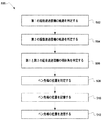
座標系および適切な専門語を確立したところで、次に、スタイラス先端112の位置を判定するための例示的な方法について述べる。ここで図5に目を向けると、フローチャート500が示されている。フローチャート500は、スタイラス先端が筆記材料106と接触しているときに、図4に関して上述したxyz座標系に対して電子スタイラス102のスタイラス先端112の正確な位置を判定する際に実施することのできる例示的な動作を示している。図6〜8に、図5に示す様々な動作がどのように電子スタイラスシステム100と物理的および空間的に関係するかを示す。
Having established the coordinate system and appropriate terminology, an exemplary method for determining the position of the
前述のように、一実施形態では、フローチャート500に示す動作の全部または一部をベースユニットマイクロコントローラ302中で、またはマイクロコントローラ302によって実施することができる。他の実施形態では、動作は他のマイクロコントローラ、プロセッサ、コンピューティングデバイス、またはコンピューティングシステム中で実施することができる。動作(operations)は、(1)プロセッサによって実施される一連のステップとして、および(2)相互接続されたマシンのモジュール(modules)として実施することができる。実施は、性能および/または適用例の要件に応じて選択できる問題である。したがって、本明細書に述べる実施形態を構成する動作(operations)は、動作(operations)、ステップ(steps)、オブジェクト(objects)、またはモジュール(modules)として、様々に呼ばれる。
As described above, in one embodiment, all or part of the operations shown in
図5に示すように、動作500の開始時、第1の軌跡判定動作502で超音波送信機118の軌跡(「第1の軌跡」)を判定する。本明細書では、第1の軌跡602(図6)は、中心点P1604から等距離にある同一平面上の点の円であり、半径R1606を有する。図6に示すように、第1の軌跡602は、第1の超音波送信機118と第1の超音波受信機130との間の距離d11418、および第1の超音波送信機118と第2の超音波受信機132との間の距離d12420が計算された場合に、第1の超音波送信機118が存在する可能性のあるすべての点を含む。第1の軌跡602がある平面は、y軸406に平行であり、x軸404に垂直である。第1の中心点P1604は、第1の軌跡602によって規定される平面がx軸404と交差する点である。図6に示すように、第1の中心点P1604は、x軸404上の原点402から距離X1608のところに位置する。
As shown in FIG. 5, at the start of the
前述のことから理解されるように、第1の軌跡602は、距離X1608および半径R1606を定めることによって規定することができる。したがって一実施形態によれば、第1の軌跡判定動作502は、X1608およびR1606を判定することを含む。一実施形態によれば、X1608およびR1606の判定は、したがって第1の軌跡602の判定は、以下の式(2)〜(4)を使用して行うことができる。
As will be appreciated from the foregoing, the

当業者には理解されるように、式(2)〜(4)をソフトウェアおよび/またはファームウェア中で実施する方式はいくつかある。したがって、第1の軌跡判定動作502は、式(2)〜(4)に関するいずれか1つの特定の実装形態に限定されるものではない。
As will be appreciated by those skilled in the art, there are several ways to implement equations (2)-(4) in software and / or firmware. Therefore, the first
次に、第2の軌跡判定動作504で、第2の超音波送信機120の軌跡(「第2の軌跡」)を判定する。第1の軌跡602と同様、第2の軌跡702(図7)は、中心点P2704から等距離にある同一平面上の点の円であり、半径R2706を有する。図7に示すように、第2の軌跡702は、第2の超音波送信機120と第1の超音波受信機130との間の距離d21422、および第2の超音波送信機120と第2の超音波受信機132との間の距離d22424が計算された場合に、第2の超音波送信機120が存在する可能性のあるすべての点を含む。この場合もやはり、第2の軌跡702がある平面は、y軸406に平行であり、x軸404に垂直である。第2の中心点P2704は、第2の軌跡702によって規定される平面がx軸404と交差する点である。図7に示すように、第2の中心点P2704は、x軸404上の原点402から距離X2708のところに位置する。
Next, in the second
第2の軌跡702は、距離X2708および半径R2706を定めることによって規定することができる。したがって一実施形態によれば、第2の軌跡判定動作504は、X2708およびR2706を判定することを含む。一実施形態によれば、X2708およびR2706の判定は、したがって第2の軌跡702の判定は、以下の式(5)〜(7)を利用して行うことができる。
The
式(2)〜(4)と同様、式(5)〜(7)をソフトウェアおよび/またはファームウェア中で実施する方式はいくつかある。したがって、第2の軌跡判定動作504は、式(5)〜(7)に関するいずれか1つの特定の実装形態に限定されるものではない。
Similar to equations (2)-(4), there are several ways to implement equations (5)-(7) in software and / or firmware. Therefore, the second
第2の軌跡判定動作504に続いて、傾斜角判定動作506で、第1の傾斜角θ1804および第2の傾斜角θ2802を判定する。図8に示すように、角度θ1804は、第1の超音波送信機118が第1の軌跡602上で位置する角度であって、z軸から測定した角度を表す。同様に、角度θ2802は、第2の超音波送信機120が第2の軌跡702上で位置する角度であって、z軸から測定した角度を表す。この実施形態では、角度θ1およびθ2は、原点から正のx方向で見た場合に、z軸408から時計回りに測定した角度として表される。第2の角度θ2802と第1の角度θ1804の差はβとして表すことができ、β=θ2−θ1である。
Subsequent to the second
一実施形態によれば、傾斜角判定動作506は、以下の式(8)〜(14)を利用して行うことができる。
According to one embodiment, the tilt
動作500が行われている場合はスタイラス先端112が筆記材料106と接触しているはずなので、次いで、以下の式を使用して値θ2およびθ1を判定することができる。
Since the
式(11)を解く際、P’は、スタイラスの第1の超音波送信機118と先端112との間の距離806であることに留意されたい。
Note that in solving equation (11), P ′ is the
式(12)を解く際、変数φは、計算目的のみで使用する一時的な変数であることに留意されたい。すなわち、φは、物理的に測定可能な角度に直接対応するものではない。 Note that when solving equation (12), the variable φ is a temporary variable used for calculation purposes only. That is, φ does not directly correspond to a physically measurable angle.
式(10)に関してβには2つの解βおよび−βがあったので、式(12)も同様に、以下のように2つのφの値について解くことができる。 Since β has two solutions β and −β with respect to equation (10), equation (12) can also be solved for the two values of φ as follows.
次いで、以下のように、式(13)を使用してθ1について解くことができる。
式(13) θ1=φまたはφ+π
式(12)に関してφには2つの解φ1およびφ2があったので、式(13)は、以下のように4つのθ1の値について解くことができる。
式(13−1) θ11=φ1
式(13−2) θ12=φ2
式(13−3) θ13=φ1+π
式(13−4) θ14=φ2+π
θ1について解いた後、式(14)でθ2について解くことができる。
式(14) θ2=θ1+β
式(13)に関してθ1には4つの解θ11、θ12、θ13、θ14があったので、式(14)は、4つのθ2の値について解くことができ、正と負のβ(βおよび−β)のそれぞれに2つの値が対応する。
The equation (13) can then be used to solve for θ 1 as follows:
Formula (13) θ 1 = φ or φ + π
Since there were two solutions φ 1 and φ 2 for φ with respect to equation (12), equation (13) can be solved for the four values of θ 1 as follows:
Formula (13-1) θ 11 = φ 1
Formula (13-2) θ 12 = φ 2
Formula (13-3) θ 13 = φ 1 + π
Expression (13-4) θ 14 = φ 2 + π
After solving for θ 1 , it can be solved for θ 2 using equation (14).
Expression (14) θ 2 = θ 1 + β
Since there were four solutions θ 11 , θ 12 , θ 13 , and θ 14 for θ 1 with respect to equation ( 13 ), equation ( 14 ) can be solved for four values of θ 2 , positive and negative Two values correspond to each of β (β and −β).
当業者には理解されるように、式(8)〜(14)をソフトウェアおよび/またはファームウェア中で実施する方式はいくつかある。したがって、傾斜角判定動作506は、式(8)〜(14)に関するいずれか1つの特定の実装形態に限定されるものではない。
As will be appreciated by those skilled in the art, there are several ways to implement equations (8)-(14) in software and / or firmware. Therefore, the tilt
次に、位置判定動作508で、x軸およびy軸に関してスタイラス先端112の位置を判定する。すなわち、位置判定動作508で、原点402に対するスタイラス先端112の位置を指定する(x,y)座標の対を判定する。一実施形態によれば、位置判定動作508は、以下の式(15)〜(16)を利用して行うことができる。より具体的には、xの値は、以下のように式(15)を使用して判定することができる。
式(15) x=(1+λ)X1−λX2
式(15)を満たすxの値は、ただ1つである。当業者には理解されるように、式(15)をソフトウェアおよび/またはファームウェア中で実施する方式はいくつかある。さらに、式(2)〜(14)からの適切な式を組み合わせ、代用して、他の形の式(15)に到達する方式もいくつかある。
Next, a
Formula (15) x = (1 + λ) X 1 −λX 2
There is only one value of x that satisfies Equation (15). As will be appreciated by those skilled in the art, there are several ways to implement equation (15) in software and / or firmware. In addition, there are several ways of combining and substituting appropriate equations from equations (2)-(14) to arrive at other forms of equation (15).
yの値は、以下のように式(16)を使用して判定することができる。
式(16) y=(1+λ)R1sin(θ1)−λR2sin(θ2)
前述のように、θ1について4つの可能な値があり、θ2について4つの可能な値がある。しかし、式(16)中のyについて解く中で、負でないyの値をもたらすと共に角度θ2が|θ2|<90度を満たす結果だけが、有効と見なされることになる。
The value of y can be determined using equation (16) as follows.
Expression (16) y = (1 + λ) R 1 sin (θ 1 ) −λR 2 sin (θ 2 )
As mentioned above, there are four possible values for θ 1 and four possible values for θ 2 . However, in solving for y in equation (16), only the result that yields a non-negative value of y and the angle θ 2 satisfies | θ 2 | <90 degrees will be considered valid.
理解されるように、式(16)をソフトウェアおよび/またはファームウェア中で実施して解く方式はいくつかある。どのように実施して解いても、この場合、負でないyの解だけが有効と見なされる。この負でないyの解が、判定されたxの値と共に、ペン先端のxy座標を構成する。 As will be appreciated, there are several ways to solve equation (16) by implementing it in software and / or firmware. Regardless of how they are implemented and solved, only non-negative y solutions are considered valid. This non-negative y solution together with the determined value of x constitutes the xy coordinate of the pen tip.
位置判定動作508に続いて、スタイラス先端位置記憶動作510で、スタイラス先端の位置(x,y)をスタイラス先端位置ファイルに記憶する。動作500の各々がベースユニット104中で実施される場合は、これらの位置はベースユニット104のメモリ308に記憶される。
Following the
動作500のいくつかまたはすべてがベースユニット104の外部のコンピューティングデバイスまたはプロセス中で実施される一実施形態では、これらの位置は、ベースユニット104の外部にあるコンピューティングデバイスまたはプロセスからアクセス可能なメモリに記憶される。理解されるように、動作500が何度か実施された後には、スタイラス先端位置ファイルは、所与の期間にわたるスタイラス先端112の位置を指定するいくつかの点を含むことになる。
In one embodiment where some or all of
動作500の各々がベースユニット104中で実施され、位置がベースユニット104のメモリ308に記憶される一実施形態では、スタイラス先端位置送信動作512を用いて、スタイラス先端位置ファイルに記録されたスタイラス先端位置をベースユニット104の外部のコンピューティングデバイスまたはコンピューティングプロセスに送信することができる。一実施形態では、スタイラス先端位置ファイルをコンピューティングデバイスまたはコンピューティングプロセスに送信することは、ファイルが作成されてからいくらか後で行うことになる。例えば、コンピューティングデバイスまたはプロセスからリモートにある位置で電子スタイラスシステムが使用されている間に、スタイラス先端位置を記憶する。次いで、好都合なときに、スタイラス先端位置ファイルをコンピューティングデバイスまたはプロセスに送信することができる。あるいは、スタイラス先端位置ファイルをコンピューティングデバイスまたはコンピューティングプロセスに送信することは、リアルタイムで行ってもよい。前述のように、スタイラス先端位置ファイルは、データ転送ポート142を介して外部コンピューティングデバイスまたはコンピューティングプロセスに送信することができる。やはり前述のように、データ転送ポート142は、物理的または配線式の接続ポート、無線接続ポート、あるいはリムーバブル不揮発性メモリデバイスを備えるものとすることができる。
In one embodiment where each of the
動作500の各々がベースユニット104の外部のコンピューティングデバイスまたはコンピューティングプロセス中で実施される一実施形態では、超音波送信機と超音波受信機との間の測定距離が、あるいは超音波送信機と超音波受信機との間を超音波信号が移動するのに要する測定時間が、メモリに記憶される。次いで、これらの距離または時間の測定値、あるいはこれらの距離または時間の一連の測定値は、動作500に従った処理のために外部コンピューティングデバイスまたはコンピューティングプロセスに送信される。
In one embodiment where each of
本明細書に示した様々な実施形態は、構造上の特徴および/または方法上のステップに特有の言葉で述べた。ただし、添付の特許請求の範囲に定義する本発明は、述べた特定の特徴またはステップに必ずしも限定されないことを理解されたい。そうではなく、これらの特定の特徴およびステップは、特許請求する本発明の実施に関する代表的な形として開示するものである。 The various embodiments presented herein have been described in language specific to structural features and / or method steps. However, it should be understood that the invention as defined in the appended claims is not necessarily limited to the specific features or steps described. Rather, the specific features and steps are disclosed as exemplary forms of implementing the claimed invention.
100 電子スタイラスシステム
102 電子スタイラス
104 スタイラスベースユニット
106 筆記材料
108 筆記面
110 スタイラス本体
112 スタイラス先端
114 インクまたは芯(黒鉛)を保持してスタイラス先端112から出すための機構
116 スタイラス本体110中の単一の軸
118 第1の超音波送信機
120 第2の超音波送信機
122 電磁送信機
122 IR送信機
124 スタイラスインジケータランプ
126 機能スイッチ
128 ベースユニットの本体部分
130 第1の超音波受信機
132 第2の超音波受信機
134 第1の超音波信号
136 第2の超音波信号
138 電磁受信機
138 IR受信機
140 電磁信号
142 データ転送ポート
200 電子スタイラス102の動作構成要素
202 スタイラスマイクロコントローラ
204 第1の超音波ドライバモジュール
206 第2の超音波ドライバモジュール
208 IRドライバモジュール
210 スタイラスインジケータドライバモジュール
212 スタイラス先端接触スイッチ
300 ベースユニット104の動作構成要素
302 ベースユニットマイクロコントローラ
304 第1の受信機モジュール
306 第2の受信機モジュール
308 メモリ
310 増幅器
311 第1の信号
312 自動利得制御
313 増幅信号
314 コンパレータ
315 利得制御信号
316 しきい値信号生成器
317 しきい値信号
318 単安定マルチバイブレータ
319 トリガ信号
320 増幅器
321 単安定信号
322 自動利得制御
324 コンパレータ
326 しきい値信号生成器
328 単安定マルチバイブレータ
402 xyz座標系の原点
404 x軸
406 y軸
408 z軸
412 第1と第2の超音波受信機130と132の間の距離L
414 第1と第2の超音波送信機118と120の間の距離P
416 第1の超音波送信機118とスタイラス先端112との間の距離P’
418 第1の超音波送信機118と第1の超音波受信機130との間の距離d11
420 第1の超音波送信機118と第2の超音波受信機132との間の距離d12
422 第2の超音波送信機120と第1の超音波受信機130との間の距離d21
424 第2の超音波送信機120と第2の超音波受信機132との間の距離d22
602 第1の軌跡
604 第1の中心点P1
606 半径R1
608 x軸404上の原点402からの距離X1
702 第2の軌跡
704 第2の中心点P2
706 半径R2
708 x軸404上の原点402からの距離X2
802 第2の傾斜角θ2
804 第1の傾斜角θ1
806 第1の超音波送信機118と先端112との間の距離P’
808 第1の超音波送信機118と第2の超音波送信機120との間の距離P
DESCRIPTION OF
414 Distance P between first and second
416 Distance P ′ between first
418 Distance d 11 between the first
420 Distance d 12 between first
422 Distance d 21 between the second
424 Distance d 22 between the second
602
606 radius R 1
608 Distance X 1 from
702 Second locus 704 Second center point P 2
706 radius R 2
708 Distance X 2 from
802 Second inclination angle θ 2
804 First inclination angle θ 1
806 Distance P ′ between the first
808 Distance P between the first
Claims (16)
前記所与の基準点に対して前記電子スタイラス内の第2の超音波送信機の位置軌跡を判定するステップと、
判定した前記第1の超音波送信機の位置軌跡と、判定した前記第2の超音波送信機の位置軌跡と、前記スタイラス内での前記第1の超音波送信機および前記第2の超音波送信機並びに筆記先端の相対位置とを使用して、前記所与の基準点に対する前記電子スタイラス内の前記筆記先端の位置を判定するステップとを備え、
前記第1の超音波送信機の位置軌跡を判定する前記ステップは、
前記電子スタイラス内の電磁送信機から電磁信号を送信するステップと、
前記電磁信号を電磁受信機において受信するステップと、
前記第1の超音波送信機から超音波信号を送信するステップと、
前記超音波信号を第1の超音波受信機及び第2の超音波受信機において受信するステップと、前記電磁信号は前記第1及び第2の超音波送信機のうちのいずれから前記受信された超音波信号が送信されたかを指示するものであり、
前記電磁信号が受信された時間と前記超音波信号が受信された時間との時間差に基づいて前記第1の超音波送信機と前記第1の超音波受信機との間の距離(d11)を計算するステップとを含み、
前記第1の超音波送信機と前記第2の超音波送信機は交互に前記筆記先端が筆記材料に接触していることを示す超音波信号を送信することを特徴とする方法。 Determining a position trajectory of the first ultrasonic transmitter in the electronic stylus with respect to a given reference point;
Determining a position trajectory of a second ultrasonic transmitter in the electronic stylus with respect to the given reference point;
The determined position locus of the first ultrasonic transmitter, the determined position locus of the second ultrasonic transmitter, the first ultrasonic transmitter and the second ultrasonic wave in the stylus. Determining the position of the writing tip in the electronic stylus with respect to the given reference point using a transmitter and a relative position of the writing tip;
The step of determining a position trajectory of the first ultrasonic transmitter comprises:
Transmitting an electromagnetic signal from an electromagnetic transmitter in the electronic stylus;
Receiving the electromagnetic signal at an electromagnetic receiver;
Transmitting an ultrasonic signal from the first ultrasonic transmitter;
Receiving the ultrasonic signal at a first ultrasonic receiver and a second ultrasonic receiver; and the electromagnetic signal is received from any of the first and second ultrasonic transmitters. Indicates whether an ultrasound signal has been transmitted,
The distance (d 11 ) between the first ultrasonic transmitter and the first ultrasonic receiver based on the time difference between the time when the electromagnetic signal is received and the time when the ultrasonic signal is received. Calculating
The first ultrasonic transmitter and the second ultrasonic transmitter alternately transmit an ultrasonic signal indicating that the writing tip is in contact with the writing material.
ことを特徴とする請求項1に記載の方法。 The given reference point A method according to claim 1, characterized in that located in the electronic stylus-based receiver in the unit including the first ultrasonic receiver and the second ultrasonic receiver .
ことを特徴とする請求項2に記載の方法。 The method of claim 2, wherein the given reference point is at the location of the first ultrasonic receiver of the base receiver unit.
ことを特徴とする請求項3に記載の方法。 The position trajectory of the first ultrasonic receiver relative to the reference point is further determined by calculating a distance (d 12 ) between the first ultrasonic transmitter and the second ultrasonic receiver. The method of claim 3, wherein:
ことを特徴とする請求項4に記載の方法。 The position trajectory of the second ultrasonic receiver relative to the reference point calculates the distance (d 21 ) between the second ultrasonic transmitter and the first ultrasonic receiver, and the second The method according to claim 4, characterized in that it is determined by calculating the distance (d 22 ) between the ultrasound transmitter and the second ultrasound receiver.
前記第1の超音波受信機と前記第2の超音波受信機との間の前記固定された距離は、前記所与の基準点に対する前記スタイラスの先端の位置を判定する際に使用される
ことを特徴とする請求項2に記載の方法。 It said first ultrasonic receiver and the second ultrasonic receiver of the base unit is at a position of a fixed distance from each other in the base unit,
The fixed distance between the first ultrasonic receiver and the second ultrasonic receiver is used in determining the position of the stylus tip relative to the given reference point. The method according to claim 2.
前記スタイラスは、前記スタイラス内の第1の固定された位置にある第1の超音波送信機と、前記スタイラス内の第2の固定された位置にある第2の超音波送信機とを有し、
前記座標系に対して前記第1の超音波送信機の第1の位置軌跡を判定するステップと、
前記座標系に対して前記第2の超音波送信機の第2の位置軌跡を判定するステップと、
前記第1の超音波送信機の第1の傾斜角を判定するステップと、
前記第2の超音波送信機の第2の傾斜角を判定するステップと、
前記第1の位置軌跡、前記第2の位置軌跡、前記第1の傾斜角、前記第2の傾斜角、第1の超音波受信機および第2の超音波受信機並びに前記スタイラスの先端の互いに対する位置を使用して、前記座標系に対する前記スタイラスの先端の位置を判定するステップとを備え、
前記第1の超音波送信機の位置軌跡を判定する前記ステップは、
前記スタイラス内の電磁送信機から電磁信号を送信するステップと、
前記電磁信号を電磁受信機において受信するステップと、
前記第1の超音波送信機から超音波信号を送信するステップと、
前記超音波信号を第1の超音波受信機及び第2の超音波受信機において受信するステップと、前記電磁信号は前記第1及び第2の超音波送信機のうちのいずれから前記受信された超音波信号が送信されたかを指示するものであり、
前記電磁信号が受信された時間と前記超音波信号が受信された時間との時間差に基づいて前記第1の超音波送信機と前記第1の超音波受信機との間の距離を計算するステップとを含み、
前記第1の超音波送信機と前記第2の超音波送信機は交互に前記筆記先端が筆記材料に接触していることを示す超音波信号を送信することを特徴とする方法。 A method for determining the position of the tip of a stylus with respect to a coordinate system,
The stylus has a first ultrasonic transmitter at a first fixed position in the stylus and a second ultrasonic transmitter at a second fixed position in the stylus. ,
Determining a first position trajectory of the first ultrasonic transmitter with respect to the coordinate system;
Determining a second position trajectory of the second ultrasonic transmitter with respect to the coordinate system;
Determining a first tilt angle of the first ultrasonic transmitter;
Determining a second tilt angle of the second ultrasonic transmitter;
The first position trajectory, the second position trajectory, the first tilt angle, the second tilt angle, the first ultrasonic receiver, the second ultrasonic receiver, and the tip of the stylus are mutually connected. Determining the position of the tip of the stylus relative to the coordinate system using the position relative to
The step of determining a position trajectory of the first ultrasonic transmitter comprises:
Transmitting an electromagnetic signal from an electromagnetic transmitter in the stylus;
Receiving the electromagnetic signal at an electromagnetic receiver;
Transmitting an ultrasonic signal from the first ultrasonic transmitter;
Receiving the ultrasonic signal at a first ultrasonic receiver and a second ultrasonic receiver; and the electromagnetic signal is received from any of the first and second ultrasonic transmitters. Indicates whether an ultrasound signal has been transmitted,
Calculating a distance between the first ultrasonic transmitter and the first ultrasonic receiver based on a time difference between a time when the electromagnetic signal is received and a time when the ultrasonic signal is received. Including
The first ultrasonic transmitter and the second ultrasonic transmitter alternately transmit an ultrasonic signal indicating that the writing tip is in contact with the writing material.
をさらに備えることを特徴とする請求項7に記載の方法。 The method of claim 7, further comprising: storing the determined position of the tip of the stylus.
をさらに備えることを特徴とする請求項8に記載の方法。 9. The method of claim 8, further comprising: transmitting the determined position of the stylus tip to a computing device.
前記電子ペン内の前記第1の超音波送信機と前記ベースユニット内の第2の超音波受信機との間の距離を判定するステップと、
前記電子ペン内の第2の超音波送信機と前記ベースユニット内の前記第1の超音波受信機との間の距離を判定するステップと、
前記電子ペン内の前記第2の超音波送信機と前記ベースユニット内の前記第2の超音波受信機との間の距離を判定するステップと、
判定した各距離を不揮発性メモリに記憶するステップとを備え、
前記第1の超音波送信機と前記第1の超音波受信機との間の距離を判定するステップは、
前記電子ペン内の電磁送信機から電磁信号を送信するステップと、
前記電磁信号を前記ベースユニット内の第1の電磁受信機において受信するステップと、
前記第1の超音波送信機から超音波信号を送信するステップと、
前記超音波信号を前記第1の超音波受信機及び前記第2の超音波受信機において受信するステップと前記電磁信号は前記第1及び第2の超音波送信機のうちのいずれから前記受信された超音波信号が送信されたかを指示するものであり、
前記電磁信号が受信された時間と前記超音波信号が受信された時間との時間差に基づいて前記第1の超音波送信機と前記第1の超音波受信機との間の距離を計算するステップとを含み、
前記第1の超音波送信機と前記第2の超音波送信機は交互に前記筆記先端が筆記材料に接触していることを示す超音波信号を送信することを特徴とする方法。 Determining a distance between a first ultrasonic transmitter in the electronic pen and a first ultrasonic receiver in the base unit;
Determining a distance between the first ultrasonic transmitter in the electronic pen and a second ultrasonic receiver in the base unit;
Determining a distance between a second ultrasonic transmitter in the electronic pen and the first ultrasonic receiver in the base unit;
Determining a distance between the second ultrasonic transmitter in the electronic pen and the second ultrasonic receiver in the base unit;
Storing each determined distance in a non-volatile memory,
Determining the distance between the first ultrasonic transmitter and the first ultrasonic receiver;
Transmitting an electromagnetic signal from an electromagnetic transmitter in the electronic pen;
Receiving the electromagnetic signal at a first electromagnetic receiver in the base unit;
Transmitting an ultrasonic signal from the first ultrasonic transmitter;
Receiving the ultrasonic signal at the first ultrasonic receiver and the second ultrasonic receiver , and receiving the electromagnetic signal from any one of the first and second ultrasonic transmitters. Indicates whether an ultrasonic signal has been transmitted,
Calculating a distance between the first ultrasonic transmitter and the first ultrasonic receiver based on a time difference between a time when the electromagnetic signal is received and a time when the ultrasonic signal is received. Including
The first ultrasonic transmitter and the second ultrasonic transmitter alternately transmit an ultrasonic signal indicating that the writing tip is in contact with the writing material.
ことを特徴とする請求項10に記載の方法。 The method of claim 10, wherein a distance between the first ultrasonic transmitter and the first ultrasonic receiver is determined using a microcontroller in the base unit. .
ことを特徴とする請求項11に記載の方法。 The method of claim 11, wherein a distance between the first ultrasonic transmitter and the first ultrasonic receiver is stored in a non-volatile memory in the base unit.
ことを特徴とする請求項12に記載の方法。 The method of claim 12, wherein the stored distance between the first ultrasound transmitter and the first ultrasound receiver is transmitted to a computing device.
前記スタイラスは、前記スタイラス内の第1の固定された位置にある第1の超音波送信機と、前記スタイラス内の第2の固定された位置にある第2の超音波送信機とを有し、
電子スタイラス内の第1の超音波送信機とベースユニット内の第1の超音波受信機との間の距離を受け取るステップと、
前記電子スタイラス内の前記第1の超音波送信機と前記ベースユニット内の第2の超音波受信機との間の距離を受け取るステップと、
前記電子スタイラス内の第2の超音波送信機と前記ベースユニット内の前記第1の超音波受信機との間の距離を受け取るステップと、
前記電子スタイラス内の前記第2の超音波送信機と前記ベースユニット内の前記第2の超音波受信機との間の距離を受け取るステップと、
受け取った前記距離を使用して、前記座標系に対する前記スタイラスの先端の位置を判定するステップと
前記第1の超音波送信機と前記第1の超音波受信機との間の距離を以下のステップで判定するものであり、
前記スタイラス内の電磁送信機から電磁信号を送信するステップと、
前記電磁信号を前記ベースユニット内の第1の電磁受信機において受信するステップと、
前記第1の超音波送信機から超音波信号を送信するステップと、
前記超音波信号を前記第1の超音波受信機及び前記第2の超音波受信機において受信するステップと、前記電磁信号は前記第1及び第2の超音波送信機のうちのいずれから前記受信された超音波信号が送信されたかを指示するものであり、
前記電磁信号が受信された時間と前記超音波信号が受信された時間との時間差に基づいて前記第1の超音波送信機と前記第1の超音波受信機との間の距離を計算するステップとを含み、
前記第1の超音波送信機と前記第2の超音波送信機は交互に前記筆記先端が筆記材料に接触していることを示す超音波信号を送信することを特徴とする方法。 A method for determining the position of the tip of a stylus with respect to a coordinate system,
The stylus has a first ultrasonic transmitter at a first fixed position in the stylus and a second ultrasonic transmitter at a second fixed position in the stylus. ,
Receiving a distance between a first ultrasonic transmitter in the electronic stylus and a first ultrasonic receiver in the base unit;
Receiving a distance between the first ultrasonic transmitter in the electronic stylus and a second ultrasonic receiver in the base unit;
Receiving a distance between a second ultrasonic transmitter in the electronic stylus and the first ultrasonic receiver in the base unit;
Receiving a distance between the second ultrasonic transmitter in the electronic stylus and the second ultrasonic receiver in the base unit;
Determining the position of the tip of the stylus with respect to the coordinate system using the received distance; and determining the distance between the first ultrasonic transmitter and the first ultrasonic receiver as follows: Is determined by
Transmitting an electromagnetic signal from an electromagnetic transmitter in the stylus;
Receiving the electromagnetic signal at a first electromagnetic receiver in the base unit;
Transmitting an ultrasonic signal from the first ultrasonic transmitter;
Receiving the ultrasonic signal at the first ultrasonic receiver and the second ultrasonic receiver; and receiving the electromagnetic signal from any of the first and second ultrasonic transmitters. Indicating whether the transmitted ultrasonic signal has been transmitted,
Calculating a distance between the first ultrasonic transmitter and the first ultrasonic receiver based on a time difference between a time when the electromagnetic signal is received and a time when the ultrasonic signal is received. Including
The first ultrasonic transmitter and the second ultrasonic transmitter alternately transmit an ultrasonic signal indicating that the writing tip is in contact with the writing material.
前記スタイラス内に位置する第2の超音波送信機と、前記2つの超音波受信機のそれぞれとの間の距離を受け取るステップと、
受け取った前記距離、前記2つの超音波送信機間の固定された距離、前記2つの超音波受信機関の固定された距離、前記超音波送信機のうちの一方に対する前記スタイラスの先端の位置を使用して、前記ベースユニットに対する前記スタイラスの先端の位置を判定するステップとを備え、
前記第1の超音波送信機と前記2つの超音波受信機の1つとの間の距離を以下のステップで判定するものであり、
前記スタイラス内の電磁送信機から電磁信号を送信するステップと、
前記電磁信号を前記ベースユニット中の第1の電磁受信機において受信するステップと、
前記第1の超音波送信機から超音波信号を送信するステップと、
前記超音波信号を前記2つの超音波受信機において受信するステップと、前記電磁信号は前記第1及び第2の超音波送信機のうちのいずれから前記受信された超音波信号が送信されたかを指示するものであり、
前記電磁信号が受信された時間と前記超音波信号が受信された時間との時間差に基づいて前記第1の超音波送信機と前記2つの超音波受信機の1つとの間の距離を計算するステップとを含み、
前記第1の超音波送信機と前記第2の超音波送信機は交互に前記筆記先端が筆記材料に接触していることを示す超音波信号を送信することを特徴とする方法。 Receiving a distance between a first ultrasonic transmitter located in the stylus and each of the two ultrasonic receivers located in the base unit;
Receiving a distance between a second ultrasonic transmitter located within the stylus and each of the two ultrasonic receivers;
Use the received distance, the fixed distance between the two ultrasonic transmitters, the fixed distance of the two ultrasonic receivers, the position of the tip of the stylus with respect to one of the ultrasonic transmitters And determining the position of the tip of the stylus with respect to the base unit,
Determining the distance between the first ultrasonic transmitter and one of the two ultrasonic receivers by the following steps:
Transmitting an electromagnetic signal from an electromagnetic transmitter in the stylus;
Receiving the electromagnetic signal at a first electromagnetic receiver in the base unit;
Transmitting an ultrasonic signal from the first ultrasonic transmitter;
Receiving the ultrasonic signal at the two ultrasonic receivers, and whether the electromagnetic signal is transmitted from the first ultrasonic transmitter or the second ultrasonic transmitter. Is to instruct
Calculate a distance between the first ultrasonic transmitter and one of the two ultrasonic receivers based on a time difference between the time when the electromagnetic signal is received and the time when the ultrasonic signal is received. Including steps,
The first ultrasonic transmitter and the second ultrasonic transmitter alternately transmit an ultrasonic signal indicating that the writing tip is in contact with the writing material.
前記第1の送信機と前記ベースユニット内の第2の超音波受信機との間を超音波信号が伝播するのに必要な時間を示す第2の時間値を受け取るステップと、
前記電子ペン内の第2の超音波送信機と前記第1の超音波受信機との間を超音波信号が伝播するのに必要な時間を示す第3の時間値を受け取るステップと、
前記第2の超音波送信機と前記第2の超音波受信機との間を超音波信号が伝播するのに必要な時間を示す第4の時間値を受け取るステップと、
前記各時間値、前記2つの超音波送信機間の固定された距離、前記2つの超音波受信機間の固定された距離、前記超音波送信機のうちの一方に対する前記電子ペンの先端の位置を使用して、前記ベースユニットに対する前記電子ペンの先端の位置を判定するステップとを備え、
前記第1の超音波送信機と前記第1の超音波受信機との間を前記超音波信号が伝播するのに必要な時間を示す時間値は以下のステップで判定されるものであり、
前記電子ペン内の電磁送信機から電磁信号を送信するステップと、
前記電磁信号を前記ベースユニット内の第1の電磁受信機において受信するステップと、
前記第1の超音波送信機から超音波信号を送信するステップと、
前記超音波信号を第1の超音波受信機及び第2の超音波受信機において受信するステップと、前記電磁信号は前記第1及び第2の超音波送信機のうちのいずれから前記受信された超音波信号が送信されたかを指示するものであり、
前記電磁信号が受信された時間と前記超音波信号が受信された時間との時間差に基づいて前記第1の超音波送信機と前記第1の超音波受信機との間を前記超音波信号が伝播するのに必要な時間を計算するステップとを含み、
前記第1の超音波送信機と前記第2の超音波送信機は交互に前記筆記先端が筆記材料に接触していることを示す超音波信号を送信することを特徴とする方法。 Receiving a first time value indicative of a time required for the ultrasonic signal to propagate between a first ultrasonic transmitter in the electronic pen and a first ultrasonic receiver in the base unit;
Receiving a second time value indicative of a time required for an ultrasonic signal to propagate between the first transmitter and a second ultrasonic receiver in the base unit;
Receiving a third time value indicative of a time required for an ultrasonic signal to propagate between a second ultrasonic transmitter in the electronic pen and the first ultrasonic receiver;
Receiving a fourth time value indicative of a time required for an ultrasonic signal to propagate between the second ultrasonic transmitter and the second ultrasonic receiver;
Each time value, a fixed distance between the two ultrasonic transmitters, a fixed distance between the two ultrasonic receivers, a position of the tip of the electronic pen relative to one of the ultrasonic transmitters Determining the position of the tip of the electronic pen relative to the base unit using
The time value indicating the time required for the ultrasonic signal to propagate between the first ultrasonic transmitter and the first ultrasonic receiver is determined by the following steps:
Transmitting an electromagnetic signal from an electromagnetic transmitter in the electronic pen;
Receiving the electromagnetic signal at a first electromagnetic receiver in the base unit;
Transmitting an ultrasonic signal from the first ultrasonic transmitter;
Receiving the ultrasonic signal at a first ultrasonic receiver and a second ultrasonic receiver; and the electromagnetic signal is received from any of the first and second ultrasonic transmitters. Indicates whether an ultrasound signal has been transmitted,
Based on the time difference between the time when the electromagnetic signal is received and the time when the ultrasonic signal is received, the ultrasonic signal is transmitted between the first ultrasonic transmitter and the first ultrasonic receiver. Calculating the time required to propagate, and
The first ultrasonic transmitter and the second ultrasonic transmitter alternately transmit an ultrasonic signal indicating that the writing tip is in contact with the writing material.
Applications Claiming Priority (1)
| Application Number | Priority Date | Filing Date | Title |
|---|---|---|---|
| US10/367,485 US7489308B2 (en) | 2003-02-14 | 2003-02-14 | Determining the location of the tip of an electronic stylus |
Publications (3)
| Publication Number | Publication Date |
|---|---|
| JP2004246904A JP2004246904A (en) | 2004-09-02 |
| JP2004246904A5 JP2004246904A5 (en) | 2007-04-05 |
| JP4390582B2 true JP4390582B2 (en) | 2009-12-24 |
Family
ID=32736398
Family Applications (1)
| Application Number | Title | Priority Date | Filing Date |
|---|---|---|---|
| JP2004038977A Expired - Fee Related JP4390582B2 (en) | 2003-02-14 | 2004-02-16 | Electronic stylus and method for determining position of tip of stylus |
Country Status (6)
| Country | Link |
|---|---|
| US (2) | US7489308B2 (en) |
| EP (1) | EP1450296A3 (en) |
| JP (1) | JP4390582B2 (en) |
| KR (1) | KR100996758B1 (en) |
| CN (1) | CN100426214C (en) |
| BR (1) | BRPI0400130A (en) |
Families Citing this family (118)
| Publication number | Priority date | Publication date | Assignee | Title |
|---|---|---|---|---|
| KR101027450B1 (en) | 2002-04-15 | 2011-04-06 | 에포스 디벨롭먼트 리미티드 | Method and system for obtaining positioning data |
| US7489308B2 (en) | 2003-02-14 | 2009-02-10 | Microsoft Corporation | Determining the location of the tip of an electronic stylus |
| JP4143462B2 (en) * | 2003-04-09 | 2008-09-03 | シャープ株式会社 | Pen input display device |
| WO2005111653A2 (en) | 2004-05-17 | 2005-11-24 | Epos Technologies Limited | Acoustic robust synchronization signaling for acoustic positioning system |
| US8160363B2 (en) * | 2004-09-25 | 2012-04-17 | Samsung Electronics Co., Ltd | Device and method for inputting characters or drawings in a mobile terminal using a virtual screen |
| WO2006035443A2 (en) | 2004-09-29 | 2006-04-06 | Tel Hashomer Medical Research Infrastructure And Services Ltd. | Monitoring of convection enhanced drug delivery |
| US20060097997A1 (en) * | 2004-10-21 | 2006-05-11 | Borgaonkar Shekhar R | Method and system for capturing data using a digital pen |
| US7367944B2 (en) | 2004-12-13 | 2008-05-06 | Tel Hashomer Medical Research Infrastructure And Services Ltd. | Method and system for monitoring ablation of tissues |
| AU2006225986B2 (en) * | 2005-03-23 | 2011-09-01 | Qualcomm Incorporated | Method and system for digital pen assembly |
| KR100534590B1 (en) * | 2005-05-26 | 2005-12-08 | 서종범 | Input device and position recognition method using ultrasound |
| JP4728740B2 (en) * | 2005-08-23 | 2011-07-20 | Necディスプレイソリューションズ株式会社 | Electronic pen, electronic blackboard system, and projector system |
| GB2432341B (en) * | 2005-10-29 | 2009-10-14 | Hewlett Packard Development Co | Marking material |
| KR100813998B1 (en) * | 2006-10-17 | 2008-03-14 | (주)펜앤프리 | Method and apparatus for tracking 3-dimensional position of the object |
| US20080169132A1 (en) * | 2007-01-03 | 2008-07-17 | Yao Ding | Multiple styli annotation system |
| US8144148B2 (en) * | 2007-02-08 | 2012-03-27 | Edge 3 Technologies Llc | Method and system for vision-based interaction in a virtual environment |
| CA2680226A1 (en) | 2007-03-14 | 2008-09-18 | Epos Development Ltd. | Mems microphone |
| US20080309641A1 (en) * | 2007-06-15 | 2008-12-18 | Jacob Harel | Interactivity in a large flat panel display |
| US20080309645A1 (en) * | 2007-06-15 | 2008-12-18 | Cheng Uei Precision Industry Co., Ltd. | Mobile electronic device |
| US9181555B2 (en) | 2007-07-23 | 2015-11-10 | Ramot At Tel-Aviv University Ltd. | Photocatalytic hydrogen production and polypeptides capable of same |
| US8587953B2 (en) * | 2008-01-07 | 2013-11-19 | Apple Inc. | Flexible data cable |
| KR20090091442A (en) * | 2008-02-25 | 2009-08-28 | (주)펜앤프리 | Apparatus for generating input signal and input system and method using the same |
| KR100945521B1 (en) * | 2008-03-26 | 2010-03-09 | (주)펜앤프리 | System and method for inputting document information |
| US8743091B2 (en) * | 2008-07-31 | 2014-06-03 | Apple Inc. | Acoustic multi-touch sensor panel |
| US8110744B2 (en) | 2008-08-19 | 2012-02-07 | Apple Inc. | Flexible shielded cable |
| KR101542129B1 (en) | 2008-10-24 | 2015-08-06 | 삼성전자 주식회사 | Input Device For Foldable Display Device And Input Method Thereof |
| US20100258359A1 (en) * | 2009-04-14 | 2010-10-14 | Jacob Ari Stein | Portable electronic writing pad |
| US8120994B2 (en) * | 2009-04-28 | 2012-02-21 | Luidia, Inc. | Digital transcription system utilizing acoustical detectors having apertures with a vertical orientation relative to the work surface |
| US8064290B2 (en) * | 2009-04-28 | 2011-11-22 | Luidia, Inc. | Digital transcription system utilizing small aperture acoustical sensors |
| US9417700B2 (en) | 2009-05-21 | 2016-08-16 | Edge3 Technologies | Gesture recognition systems and related methods |
| US8324517B2 (en) * | 2009-12-19 | 2012-12-04 | Luidia, Inc. | Pen transcription system utilizing a spatial filter for limiting interference |
| US20110162894A1 (en) * | 2010-01-06 | 2011-07-07 | Apple Inc. | Stylus for touch sensing devices |
| US8922530B2 (en) * | 2010-01-06 | 2014-12-30 | Apple Inc. | Communicating stylus |
| JP4857385B2 (en) * | 2010-01-12 | 2012-01-18 | パナソニック株式会社 | Electronic pen system |
| JP5442479B2 (en) | 2010-02-05 | 2014-03-12 | 株式会社ワコム | Indicator, position detection device and position detection method |
| US9405404B2 (en) | 2010-03-26 | 2016-08-02 | Autodesk, Inc. | Multi-touch marking menus and directional chording gestures |
| US8396252B2 (en) | 2010-05-20 | 2013-03-12 | Edge 3 Technologies | Systems and related methods for three dimensional gesture recognition in vehicles |
| EP3410280A1 (en) * | 2010-06-11 | 2018-12-05 | Microsoft Technology Licensing, LLC | Object orientation detection with a digitizer |
| US8655093B2 (en) | 2010-09-02 | 2014-02-18 | Edge 3 Technologies, Inc. | Method and apparatus for performing segmentation of an image |
| US8467599B2 (en) | 2010-09-02 | 2013-06-18 | Edge 3 Technologies, Inc. | Method and apparatus for confusion learning |
| US8582866B2 (en) | 2011-02-10 | 2013-11-12 | Edge 3 Technologies, Inc. | Method and apparatus for disparity computation in stereo images |
| US8666144B2 (en) | 2010-09-02 | 2014-03-04 | Edge 3 Technologies, Inc. | Method and apparatus for determining disparity of texture |
| US9639178B2 (en) | 2010-11-19 | 2017-05-02 | Apple Inc. | Optical stylus |
| US8766954B2 (en) | 2010-12-21 | 2014-07-01 | Motorola Mobility Llc | Active stylus for use with touch-sensitive interfaces and corresponding method |
| US8970589B2 (en) | 2011-02-10 | 2015-03-03 | Edge 3 Technologies, Inc. | Near-touch interaction with a stereo camera grid structured tessellations |
| KR20120139365A (en) * | 2011-06-17 | 2012-12-27 | 삼성전자주식회사 | Electronical chalkboard system, control method thereof, and pointing device |
| US8907931B2 (en) * | 2011-06-20 | 2014-12-09 | Sony Corporation | Electronic terminal, input correction method, and program |
| CN102253769A (en) * | 2011-08-12 | 2011-11-23 | 宁波易方教育科技发展有限公司 | Handwriting input calibrator and calibration method thereof |
| US9323348B2 (en) | 2011-11-09 | 2016-04-26 | Crayola Llc | Stylus having sensing and transmitting capabilities |
| US9672609B1 (en) | 2011-11-11 | 2017-06-06 | Edge 3 Technologies, Inc. | Method and apparatus for improved depth-map estimation |
| US9063591B2 (en) | 2011-11-30 | 2015-06-23 | Google Technology Holdings LLC | Active styluses for interacting with a mobile device |
| US8963885B2 (en) | 2011-11-30 | 2015-02-24 | Google Technology Holdings LLC | Mobile device for interacting with an active stylus |
| KR101318450B1 (en) * | 2012-02-17 | 2013-10-15 | 주식회사 피엔에프 | Measuring device for position of electronic pen's end for elecronic equipment |
| KR101379357B1 (en) * | 2012-02-17 | 2014-03-28 | 주식회사 피엔에프 | Position information inputting keyboard and keyboard system |
| CN102609149A (en) * | 2012-03-06 | 2012-07-25 | 姜林春 | Touch/remote control computer display screen device |
| US9116571B2 (en) * | 2012-03-27 | 2015-08-25 | Adonit Co., Ltd. | Method and system of data input for an electronic device equipped with a touch screen |
| US20130278537A1 (en) * | 2012-04-19 | 2013-10-24 | Motorola Mobility, Inc. | Touchscreen writing system |
| US9690394B2 (en) | 2012-09-14 | 2017-06-27 | Apple Inc. | Input device having extendable nib |
| US9639179B2 (en) | 2012-09-14 | 2017-05-02 | Apple Inc. | Force-sensitive input device |
| KR101361365B1 (en) * | 2012-09-26 | 2014-02-11 | 한국과학기술원 | Method and apparatus for controlling user terminal using magnetic field |
| US9921626B2 (en) * | 2012-09-28 | 2018-03-20 | Atmel Corporation | Stylus communication with near-field coupling |
| US9335872B2 (en) | 2012-10-01 | 2016-05-10 | Stmicroelectronics Asia Pacific Pte Ltd | Hybrid stylus for use in touch screen applications |
| US9575590B2 (en) * | 2012-11-27 | 2017-02-21 | Beijing Lenovo Software Ltd | Input method and input apparatus |
| ES2893410T3 (en) * | 2012-11-29 | 2022-02-09 | Imran Haddish | Virtual and augmented reality instruction system |
| US9430061B2 (en) * | 2013-03-07 | 2016-08-30 | Qualcomm Incorporated | Ultrasonic hybrid input device and corresponding tuning method |
| US20140282269A1 (en) * | 2013-03-13 | 2014-09-18 | Amazon Technologies, Inc. | Non-occluded display for hover interactions |
| US10721448B2 (en) | 2013-03-15 | 2020-07-21 | Edge 3 Technologies, Inc. | Method and apparatus for adaptive exposure bracketing, segmentation and scene organization |
| CN104063095B (en) * | 2013-03-18 | 2017-09-29 | 联想(北京)有限公司 | A kind of localization method and electronic equipment |
| US10222911B2 (en) * | 2013-04-12 | 2019-03-05 | Semiconductor Energy Laboratory Co., Ltd. | Semiconductor device and driving method of the same |
| US9235294B2 (en) | 2013-05-17 | 2016-01-12 | Blackberry Limited | Phase sensitive low power digital ultrasonic microphone |
| KR101437915B1 (en) * | 2013-05-27 | 2014-10-30 | 주식회사 피엔에프 | Ultrasonic signal receiver and position information input device having the same |
| JP2014231102A (en) | 2013-05-28 | 2014-12-11 | ブラザー工業株式会社 | Working apparatus and data processing program |
| JP2014231103A (en) * | 2013-05-28 | 2014-12-11 | ブラザー工業株式会社 | Working apparatus and data processing program |
| CN104423632B (en) * | 2013-08-19 | 2017-08-29 | 联想(北京)有限公司 | A kind of method and system of positioning to electronic pen |
| US9201522B2 (en) * | 2013-09-03 | 2015-12-01 | Qualcomm Incorporated | Acoustic position tracking system |
| KR102089469B1 (en) * | 2013-09-05 | 2020-03-16 | 현대모비스 주식회사 | Remote Control Apparatus and Method of AVN System |
| CN104571633B (en) * | 2013-10-29 | 2017-11-28 | 联想(北京)有限公司 | A kind of person's handwriting acquisition methods, device and ultrasonic electronic pen |
| CN108287640B (en) * | 2013-11-08 | 2020-07-07 | 禾瑞亚科技股份有限公司 | Transmitter and transmitting method |
| CN103698747A (en) * | 2013-12-12 | 2014-04-02 | 中国科学院自动化研究所 | Frequency division type ultrasonic positioning system and method |
| US9262012B2 (en) * | 2014-01-03 | 2016-02-16 | Microsoft Corporation | Hover angle |
| CN103838376B (en) * | 2014-03-03 | 2016-09-28 | 深圳超多维光电子有限公司 | Stereo interaction method and Three-dimensional interaction system |
| US20160004334A1 (en) * | 2014-07-03 | 2016-01-07 | Miha Abrahamsberg | Advanced wireless pointing device |
| EP3167560B1 (en) * | 2014-07-07 | 2021-06-30 | Ascensia Diabetes Care Holdings AG | Improved device pairing with a dual use piezoelectric acoustic component and vibration sensor |
| CN104317427B (en) * | 2014-10-15 | 2017-11-17 | 广东小天才科技有限公司 | A kind of ultrasonic wave writing pencil tilt calibration method and system |
| CN105786221B (en) * | 2014-12-26 | 2019-02-05 | 联想(北京)有限公司 | Information processing method and electronic equipment |
| CN107111388B (en) * | 2015-01-04 | 2020-06-05 | 微软技术许可有限责任公司 | Method and apparatus for communicating with a universal stylus of a digitizer |
| US9977519B2 (en) * | 2015-02-25 | 2018-05-22 | Synaptics Incorporated | Active pen with bidirectional communication |
| US10698504B2 (en) * | 2015-06-15 | 2020-06-30 | Microsoft Technology Licensing, Llc | Detecting input pressure on a stylus pen |
| US9898841B2 (en) * | 2015-06-29 | 2018-02-20 | Microsoft Technology Licensing, Llc | Synchronizing digital ink stroke rendering |
| WO2017044051A1 (en) * | 2015-09-07 | 2017-03-16 | Chiewcharnpipat Somboon | Digitized writing apparatus |
| US11036318B2 (en) | 2015-09-30 | 2021-06-15 | Apple Inc. | Capacitive touch or proximity detection for crown |
| US10671222B2 (en) | 2015-09-30 | 2020-06-02 | Apple Inc. | Touch sensor pattern for edge input detection |
| US10671190B2 (en) * | 2015-10-02 | 2020-06-02 | Microsoft Technology Licensing, Llc | Stylus pen with dynamic protocol selection for communication with a digitizer |
| CN105654081A (en) * | 2015-12-31 | 2016-06-08 | 田雪松 | Invigilating method |
| CN105807990B (en) * | 2016-03-01 | 2018-11-27 | 京东方科技集团股份有限公司 | Display screen, stylus and display module |
| US10564740B2 (en) | 2016-07-21 | 2020-02-18 | Samsung Electronics Co., Ltd. | Pen device—panel interaction based on electromagnetic signals output by the pen device |
| WO2018023080A2 (en) | 2016-07-29 | 2018-02-01 | Apple Inc. | Methodology and application of acoustic touch detection |
| WO2018145320A1 (en) * | 2017-02-13 | 2018-08-16 | 深圳迈瑞生物医疗电子股份有限公司 | Ultrasound medical detection device, transmission control method, imaging system and terminal |
| US11157115B2 (en) | 2017-03-31 | 2021-10-26 | Apple Inc. | Composite cover material for sensitivity improvement of ultrasonic touch screens |
| US10606418B2 (en) | 2017-03-31 | 2020-03-31 | Apple Inc. | Ultrasonic touch detection on stylus |
| CN108874181B (en) * | 2017-05-08 | 2023-05-09 | 富泰华工业(深圳)有限公司 | Electronic device with laser pen marking function and laser pen marking method |
| CN114911374A (en) | 2017-05-24 | 2022-08-16 | 苹果公司 | Systems and methods for acoustic touch and force sensing |
| US11334196B2 (en) | 2017-05-24 | 2022-05-17 | Apple Inc. | System and method for acoustic touch and force sensing |
| US11144158B2 (en) | 2017-05-24 | 2021-10-12 | Apple Inc. | Differential acoustic touch and force sensing |
| KR102384034B1 (en) * | 2017-08-21 | 2022-04-06 | 엘지전자 주식회사 | Beauty pencil and beauty system including the same |
| US10949030B2 (en) | 2017-09-26 | 2021-03-16 | Apple Inc. | Shear-poled curved piezoelectric material |
| CN107830847B (en) * | 2017-10-26 | 2020-06-23 | 重庆华渝电气集团有限公司 | Infrared ultrasonic plane positioning measurement device and positioning method |
| US10802651B2 (en) | 2018-01-30 | 2020-10-13 | Apple Inc. | Ultrasonic touch detection through display |
| US11366552B2 (en) | 2018-02-06 | 2022-06-21 | Apple, Inc. | Ultrasonic polarizer |
| CN108536318A (en) * | 2018-04-04 | 2018-09-14 | 昆山中骏博研互联网科技有限公司 | A kind of person's handwriting simultaneous techniques that the inclination based on sound wave and photoelectricity automatically corrects |
| CN109032387B (en) * | 2018-07-18 | 2021-07-06 | 华讯智控(厦门)电子科技有限公司 | Method for detecting posture of pen body through ultrasonic wave and electromagnetic positioning double sensors |
| US10725573B2 (en) | 2018-08-06 | 2020-07-28 | Apple Inc. | Annular piezoelectric structure for ultrasonic touch sensing |
| US11762485B2 (en) | 2018-10-09 | 2023-09-19 | Google Llc | Writing device with electromagnetic tracking |
| EP3936345A1 (en) * | 2020-07-07 | 2022-01-12 | Société BIC | A writing instrument configured to be tracked when contacting a writing surface and method thereof |
| US11379056B2 (en) * | 2020-09-28 | 2022-07-05 | Arian Gardner | Editor's pen pad |
| US11794107B2 (en) * | 2020-12-30 | 2023-10-24 | Activision Publishing, Inc. | Systems and methods for improved collision detection in video games |
| CN113085422B (en) * | 2021-04-30 | 2022-04-15 | 江苏经贸职业技术学院 | Dust suction device for common blackboard |
| KR102366052B1 (en) * | 2021-05-28 | 2022-02-23 | (유)벨류이 | Writing system and method using delay time reduction processing, and low complexity distance measurement algorithm based on chirp spread spectrum for the same |
| CN115904112A (en) * | 2021-09-29 | 2023-04-04 | 广州众远智慧科技有限公司 | Interaction device and touch control feedback method thereof |
Family Cites Families (21)
| Publication number | Priority date | Publication date | Assignee | Title |
|---|---|---|---|---|
| DE3214426C1 (en) * | 1982-04-20 | 1983-11-24 | Nestler Gmbh A | Electronic stylus for digitizers |
| US4814552A (en) * | 1987-12-02 | 1989-03-21 | Xerox Corporation | Ultrasound position input device |
| JPH02309209A (en) * | 1989-05-24 | 1990-12-25 | Sumitomo Heavy Ind Ltd | Apparatus for measuring wavy condition of road surface |
| US5410496A (en) * | 1989-06-13 | 1995-04-25 | Schlumberger Technology Corp. | Using degrees of freedom analysis to solve topological constraint systems for construction geometry in a computer aided design (cad) |
| WO1994011844A1 (en) * | 1992-11-17 | 1994-05-26 | Lectra Systemes | Graphic data acquisition and processing method and device |
| JP3302490B2 (en) * | 1994-04-01 | 2002-07-15 | 株式会社ウェルキャット | Communication system of portable terminal device and portable terminal device |
| JPH08137610A (en) * | 1994-11-11 | 1996-05-31 | Kazumasa Kiyama | Pen with position sensor |
| JPH09212299A (en) * | 1996-01-31 | 1997-08-15 | Canon Inc | Information input device and its method |
| JP3895406B2 (en) * | 1996-03-12 | 2007-03-22 | 株式会社東邦ビジネス管理センター | Data processing apparatus and data processing method |
| US6184873B1 (en) * | 1998-01-20 | 2001-02-06 | Electronics For Imaging, Inc. | Pen positioning system |
| US6232962B1 (en) * | 1998-05-14 | 2001-05-15 | Virtual Ink Corporation | Detector assembly for use in a transcription system |
| US6335723B1 (en) * | 1998-10-02 | 2002-01-01 | Tidenet, Inc. | Transmitter pen location system |
| JP3758865B2 (en) * | 1998-12-01 | 2006-03-22 | 富士ゼロックス株式会社 | Coordinate input device |
| US6639585B1 (en) * | 1999-07-29 | 2003-10-28 | Brother Kogyo Kabushiki Kaisha | Coordinate reading device |
| US7197174B1 (en) * | 1999-09-15 | 2007-03-27 | Intel Corporation | Magnetic ink encoding pen |
| CA2390362A1 (en) * | 1999-11-08 | 2001-05-17 | Itpen Europe Limited | Apparatus for digitizing writing and drawing with erasing and/or pointing capability |
| JP2002062978A (en) * | 2000-08-21 | 2002-02-28 | Seiko Epson Corp | Electronic pen input system, receiving device, electronic pen, host device, receiving method, electronic pen input method, electronic pen position acquiring method, and information storage medium |
| JP3871524B2 (en) * | 2000-11-17 | 2007-01-24 | 富士通株式会社 | Coordinate input device |
| GB0108188D0 (en) * | 2001-04-02 | 2001-08-15 | Secr Defence | Communication system for underwater use |
| JP2003015813A (en) | 2001-07-04 | 2003-01-17 | Canon Inc | Input indicator for coordinate input device and coordinate input device |
| US7489308B2 (en) | 2003-02-14 | 2009-02-10 | Microsoft Corporation | Determining the location of the tip of an electronic stylus |
-
2003
- 2003-02-14 US US10/367,485 patent/US7489308B2/en not_active Expired - Fee Related
-
2004
- 2004-01-14 EP EP04000649A patent/EP1450296A3/en not_active Withdrawn
- 2004-01-27 BR BR0400130-3A patent/BRPI0400130A/en not_active IP Right Cessation
- 2004-02-12 CN CNB2004100053927A patent/CN100426214C/en not_active Expired - Fee Related
- 2004-02-13 KR KR1020040009647A patent/KR100996758B1/en not_active IP Right Cessation
- 2004-02-16 JP JP2004038977A patent/JP4390582B2/en not_active Expired - Fee Related
-
2009
- 2009-01-08 US US12/350,255 patent/US9207813B2/en not_active Expired - Fee Related
Also Published As
| Publication number | Publication date |
|---|---|
| BRPI0400130A (en) | 2004-12-28 |
| KR100996758B1 (en) | 2010-11-25 |
| US20090153526A1 (en) | 2009-06-18 |
| EP1450296A2 (en) | 2004-08-25 |
| CN1521688A (en) | 2004-08-18 |
| JP2004246904A (en) | 2004-09-02 |
| US7489308B2 (en) | 2009-02-10 |
| CN100426214C (en) | 2008-10-15 |
| EP1450296A3 (en) | 2012-02-29 |
| KR20040073997A (en) | 2004-08-21 |
| US9207813B2 (en) | 2015-12-08 |
| US20040160429A1 (en) | 2004-08-19 |
Similar Documents
| Publication | Publication Date | Title |
|---|---|---|
| JP4390582B2 (en) | Electronic stylus and method for determining position of tip of stylus | |
| US7842893B2 (en) | Electronic pen having an ultrasonic wave controller | |
| KR100465241B1 (en) | Motion recognition system using a imaginary writing plane and method thereof | |
| US11073921B2 (en) | Electronic device for generating analogue strokes and for digitally storing the analogue strokes, and an input system and method for digitizing analogue recordings | |
| CN103744541A (en) | Writing pen, electronic terminal and writing system | |
| CN101887327B (en) | Multi-input large-area writing method, device and system | |
| CN101882032B (en) | Handwriting input method, device and system and receiver | |
| CN102681958A (en) | Transferring data using physical gesture | |
| US9471183B1 (en) | Mobile device incorporating projector and pen-location transcription system | |
| JP2013535066A (en) | Launch objects for interactive systems | |
| EP1228480B1 (en) | Method for digitizing writing and drawing with erasing and/or pointing capability | |
| CN102207801A (en) | Three-dimensional hand-writing input device and hand-writing input method | |
| US20150029164A1 (en) | Attachable accessory and method for computer recording of writing | |
| US20170371438A1 (en) | Method and system for transcribing marker locations, including erasures | |
| JP5141380B2 (en) | Handwriting handwriting input system | |
| JP3244734U (en) | Writing instrument or operating device with posture detection means | |
| JP2009181409A (en) | Handwriting input system | |
| JP5272401B2 (en) | Handwriting handwriting input system | |
| CN211577871U (en) | Electronic equipment, positioning device and positioning assembly | |
| KR102185942B1 (en) | Method, apparatus and electronic pen for acquiring gradient of electronic pen using image sensors | |
| JP2008250581A (en) | Handwriting input device | |
| KR101069992B1 (en) | Apparatus for inputting digital data using laser | |
| JP5120128B2 (en) | Handwriting handwriting input system | |
| KR20050108850A (en) | Position input instrument including digital pen | |
| JP2005157709A (en) | Electronic pen system capable of arbitrary setting of writing destination |
Legal Events
| Date | Code | Title | Description |
|---|---|---|---|
| A521 | Written amendment |
Free format text: JAPANESE INTERMEDIATE CODE: A523 Effective date: 20070215 |
|
| A621 | Written request for application examination |
Free format text: JAPANESE INTERMEDIATE CODE: A621 Effective date: 20070215 |
|
| A131 | Notification of reasons for refusal |
Free format text: JAPANESE INTERMEDIATE CODE: A131 Effective date: 20081219 |
|
| A521 | Written amendment |
Free format text: JAPANESE INTERMEDIATE CODE: A523 Effective date: 20090319 |
|
| A131 | Notification of reasons for refusal |
Free format text: JAPANESE INTERMEDIATE CODE: A131 Effective date: 20090417 |
|
| A521 | Written amendment |
Free format text: JAPANESE INTERMEDIATE CODE: A523 Effective date: 20090715 |
|
| TRDD | Decision of grant or rejection written | ||
| A01 | Written decision to grant a patent or to grant a registration (utility model) |
Free format text: JAPANESE INTERMEDIATE CODE: A01 Effective date: 20090807 |
|
| A01 | Written decision to grant a patent or to grant a registration (utility model) |
Free format text: JAPANESE INTERMEDIATE CODE: A01 |
|
| A601 | Written request for extension of time |
Free format text: JAPANESE INTERMEDIATE CODE: A601 Effective date: 20090907 |
|
| A602 | Written permission of extension of time |
Free format text: JAPANESE INTERMEDIATE CODE: A602 Effective date: 20090910 |
|
| A61 | First payment of annual fees (during grant procedure) |
Free format text: JAPANESE INTERMEDIATE CODE: A61 Effective date: 20091006 |
|
| FPAY | Renewal fee payment (event date is renewal date of database) |
Free format text: PAYMENT UNTIL: 20121016 Year of fee payment: 3 |
|
| R150 | Certificate of patent or registration of utility model |
Free format text: JAPANESE INTERMEDIATE CODE: R150 |
|
| FPAY | Renewal fee payment (event date is renewal date of database) |
Free format text: PAYMENT UNTIL: 20121016 Year of fee payment: 3 |
|
| FPAY | Renewal fee payment (event date is renewal date of database) |
Free format text: PAYMENT UNTIL: 20131016 Year of fee payment: 4 |
|
| R250 | Receipt of annual fees |
Free format text: JAPANESE INTERMEDIATE CODE: R250 |
|
| R250 | Receipt of annual fees |
Free format text: JAPANESE INTERMEDIATE CODE: R250 |
|
| S111 | Request for change of ownership or part of ownership |
Free format text: JAPANESE INTERMEDIATE CODE: R313113 |
|
| R350 | Written notification of registration of transfer |
Free format text: JAPANESE INTERMEDIATE CODE: R350 |
|
| R250 | Receipt of annual fees |
Free format text: JAPANESE INTERMEDIATE CODE: R250 |
|
| LAPS | Cancellation because of no payment of annual fees |