JP4336636B2 - Communication apparatus and communication method - Google Patents
Communication apparatus and communication method Download PDFInfo
- Publication number
- JP4336636B2 JP4336636B2 JP2004273132A JP2004273132A JP4336636B2 JP 4336636 B2 JP4336636 B2 JP 4336636B2 JP 2004273132 A JP2004273132 A JP 2004273132A JP 2004273132 A JP2004273132 A JP 2004273132A JP 4336636 B2 JP4336636 B2 JP 4336636B2
- Authority
- JP
- Japan
- Prior art keywords
- mode
- power
- notification
- change
- power saving
- Prior art date
- Legal status (The legal status is an assumption and is not a legal conclusion. Google has not performed a legal analysis and makes no representation as to the accuracy of the status listed.)
- Expired - Fee Related
Links
Images


Classifications
-
- H—ELECTRICITY
- H04—ELECTRIC COMMUNICATION TECHNIQUE
- H04W—WIRELESS COMMUNICATION NETWORKS
- H04W52/00—Power management, e.g. TPC [Transmission Power Control], power saving or power classes
- H04W52/02—Power saving arrangements
- H04W52/0209—Power saving arrangements in terminal devices
- H04W52/0212—Power saving arrangements in terminal devices managed by the network, e.g. network or access point is master and terminal is slave
- H04W52/0216—Power saving arrangements in terminal devices managed by the network, e.g. network or access point is master and terminal is slave using a pre-established activity schedule, e.g. traffic indication frame
-
- H—ELECTRICITY
- H04—ELECTRIC COMMUNICATION TECHNIQUE
- H04W—WIRELESS COMMUNICATION NETWORKS
- H04W52/00—Power management, e.g. TPC [Transmission Power Control], power saving or power classes
- H04W52/02—Power saving arrangements
- H04W52/0209—Power saving arrangements in terminal devices
- H04W52/0225—Power saving arrangements in terminal devices using monitoring of external events, e.g. the presence of a signal
- H04W52/0235—Power saving arrangements in terminal devices using monitoring of external events, e.g. the presence of a signal where the received signal is a power saving command
-
- H—ELECTRICITY
- H04—ELECTRIC COMMUNICATION TECHNIQUE
- H04W—WIRELESS COMMUNICATION NETWORKS
- H04W68/00—User notification, e.g. alerting and paging, for incoming communication, change of service or the like
-
- H—ELECTRICITY
- H04—ELECTRIC COMMUNICATION TECHNIQUE
- H04W—WIRELESS COMMUNICATION NETWORKS
- H04W84/00—Network topologies
- H04W84/18—Self-organising networks, e.g. ad-hoc networks or sensor networks
-
- Y—GENERAL TAGGING OF NEW TECHNOLOGICAL DEVELOPMENTS; GENERAL TAGGING OF CROSS-SECTIONAL TECHNOLOGIES SPANNING OVER SEVERAL SECTIONS OF THE IPC; TECHNICAL SUBJECTS COVERED BY FORMER USPC CROSS-REFERENCE ART COLLECTIONS [XRACs] AND DIGESTS
- Y02—TECHNOLOGIES OR APPLICATIONS FOR MITIGATION OR ADAPTATION AGAINST CLIMATE CHANGE
- Y02D—CLIMATE CHANGE MITIGATION TECHNOLOGIES IN INFORMATION AND COMMUNICATION TECHNOLOGIES [ICT], I.E. INFORMATION AND COMMUNICATION TECHNOLOGIES AIMING AT THE REDUCTION OF THEIR OWN ENERGY USE
- Y02D30/00—Reducing energy consumption in communication networks
- Y02D30/70—Reducing energy consumption in communication networks in wireless communication networks
Abstract
Description
本発明は、通信装置及び通信方法に関し、例えば、省電力モードの変更通知を行う技術に関する。 The present invention relates to a communication device and a communication method, and, for example, relates to a technique for performing a power saving mode change notification.
近年、IEEE802.11規格に準拠した無線インターフェースを備える無線機器が数多く製品化され利用されている。このような無線機器は一般に可搬性が高いため、携帯型の機器に多く、また携帯型の機器では多くがバッテリィで駆動されているため、電池の消費量を如何に少なくし、全体としてバッテリィの寿命を延ばすかが大きな課題となっている。 In recent years, many wireless devices having a wireless interface compliant with the IEEE 802.11 standard have been commercialized and used. Since such wireless devices are generally highly portable, many of them are portable devices, and many portable devices are driven by batteries. Extending the service life is a major issue.
IEEE802.11規格において、無線インターフェースが有効になっているときでも、実際に通信を行っている時間はまばらであることを利用して、間欠的に送受信を行うパワーセーブモード仕様が決められている。IEEE802.11規格においては、基地局であるアクセスポイントを介して他の通信機器(ステーション)と通信を行うインフラストラクチャーモードと、各ステーションがそれぞれ相互に他のステーションと通信を行うアドホックモードが存在する。前述のパワーセーブモード仕様において、インフラストラクチャーモードはIEEE802.11規格で詳細まで規定されており既に多くの製品群で採用され使われている。一方で、アドホックモードにおけるパワーセーブモード仕様は不明確な点が多く、まだ製品となっているものは存在しない。 In the IEEE 802.11 standard, even when the wireless interface is enabled, the power saving mode specification for intermittent transmission / reception is determined by utilizing the fact that the actual communication time is sparse. . In the IEEE 802.11 standard, there are an infrastructure mode in which communication is performed with other communication devices (stations) via an access point as a base station, and an ad hoc mode in which each station communicates with other stations. . In the aforementioned power save mode specification, the infrastructure mode is defined in detail in the IEEE 802.11 standard, and has already been adopted and used in many product groups. On the other hand, the power save mode specification in the ad hoc mode has many unclear points, and there is no product yet.
インフラストラクチャーモードとアドホックモードの大きな違いは、インフラストラクチャーモードではアクセスポイントが常に通信の相手であり、アクセスポイントはパワーセーブモードを利用できない仕組み(常にアクティブモード)になっている。これに対してアドホックモードでは、通信相手となるステーションもパワーセーブモードを利用している可能性があり、相手の状態を常に意識してデータを送信する必要が生じる。 The major difference between the infrastructure mode and the ad hoc mode is that the access point is always a communication partner in the infrastructure mode, and the access point has a mechanism that cannot use the power save mode (always active mode). On the other hand, in the ad hoc mode, there is a possibility that a station serving as a communication partner also uses the power save mode, and it is necessary to always transmit data while being aware of the state of the other party.
IEEE802.11のパワーセーブモードを利用すると、ステーションはAwake状態とSleep状態の二つの状態を取りうる。Awake状態はデータの送受信を行うことが可能だが、Sleep状態ではデータの送受信を行うことができない。アドホックモードにおいて、もし電力モードを変更したいと思っても、通信相手がそのパケットを受け取れない状態、つまり、通信相手がSleep状態のときに、電力モードの変更通知を行っても、通信相手は電力モードの変更を認識できないので、電力モードの通知は相手の状態を見てから行う必要がある。このようにアドホックモードでは、通信相手の状態管理を必要とし、そのメカニズムが複雑であるため実用に至っていない。
前述のように、アドホックモードにおいてパワーセーブを実現することができないという問題があった。その原因は、アドホックモードにおいては通信相手が相互にパワーセーブモードを利用することが可能であり、各ステーションは通信相手の状態を常に管理する必要が生じることに起因する。 As described above, there is a problem that power saving cannot be realized in the ad hoc mode. The cause is that in the ad hoc mode, communication partners can mutually use the power save mode, and each station needs to always manage the state of the communication partner.
さらに、アドホックモードでは、通信相手は一台とは限らず、そのネットワーク上に参加したステーションの全てが候補となる。これら全てのステーションとの通信を考慮しつつ、実装負荷に応じて簡略的な実装も許してパワーセーブを実現するための提案はなされていない。 Further, in the ad hoc mode, the communication partner is not limited to one, and all the stations that have joined on the network are candidates. While considering communication with all these stations, no proposal has been made to realize power saving by allowing simple mounting according to mounting load.
本発明は、通信装置同士が中継装置を介さずに直接通信するネットワークにおける通信装置であって、電力モードを省電力モードに変更する変更手段と、前記ネットワーク内のいずれか1つの通信装置により報知信号が送信されてから次の報知信号が送信されるまでの間の、省電力モードの他の通信装置が通信可能状態になる期間を判別する判別手段と、前記変更手段により電力モードを省電力モードに変更する際は、前記判別手段により判別された期間に、前記ネットワーク内の他の通信装置に対して電力モードの変更を通知する通知手段と、を有することを特徴とする。 The present invention is a communication device in a network in which communication devices communicate directly with each other without using a relay device, and is notified by changing means for changing a power mode to a power saving mode and any one of the communication devices in the network. A determination unit that determines a period during which another communication device in a power saving mode is in a communicable state from when a signal is transmitted to when the next notification signal is transmitted, and the power mode is reduced by the changing unit. When changing to the mode, it has a notification means for notifying other communication devices in the network of the change of the power mode during the period determined by the determination means .
また、本発明は、通信装置であって、電力モードを変更する変更手段と、電力モードの変更を他の通信装置に通知する通知手段と、前記通知手段による通知に対する応答を検知する検知手段と、前記検知手段による検知に基づいて、電力モードの変更を通知する相手装置が省電力モードか否かを判別する判別手段と、を有し、前記通知手段は、前記判別手段による判別結果に基づいて、電力モードの変更を前記相手装置へ通知することを特徴とする。 The present invention is also a communication device, a changing unit for changing the power mode, a notification unit for notifying another communication device of the change of the power mode, and a detection unit for detecting a response to the notification by the notification unit, Determining means for determining whether or not the counterpart device that notifies the change of the power mode is in the power saving mode based on detection by the detecting means, and the notifying means is based on the determination result by the determining means. Then, the change of the power mode is notified to the counterpart device.
また、本発明は、通信装置同士が中継装置を介さずに直接通信するネットワークにおける通信装置の通信方法であって、電力モードを省電力モードに変更する変更工程と、前記ネットワーク内のいずれか1つの通信装置により報知信号が送信されてから次の報知信号が送信されるまでの間の、省電力モードの他の通信装置が通信可能状態になる期間を判別する判別工程と、前記変更工程において前記省電力モードに変更する際は、前記判別工程において判別された期間に、前記他の通信装置に対して省電力モードへの変更を通知する通知工程と、を有することを特徴とする。 The present invention is also a communication method for a communication apparatus in a network in which communication apparatuses communicate directly with each other without using a relay apparatus, the changing step of changing a power mode to a power saving mode, and any one of the networks A determination step of determining a period in which another communication device in a power saving mode is in a communicable state between the transmission of a notification signal by one communication device and the transmission of the next notification signal; when changing to the power saving mode, to the determined period in the determination step, and having a notification step of notifying the change to the power saving mode to the other communication device.
また、本発明は、通信装置の通信方法であって、電力モードを変更する変更工程と、電力モードの変更を他の通信装置に通知する通知工程と、前記通知工程における通知に対する応答を検知する検知工程と、
前記検知工程における検知に基づいて、電力モードの変更を通知する相手装置が省電力モードか否かを判別する判別工程と、を有し、前記通知工程において、前記判別工程における判別結果に基づいて、電力モードの変更を前記相手装置へ通知することを特徴とする。
In addition, the present invention is a communication method for a communication device, and includes a change step for changing a power mode, a notification step for notifying another communication device of the change of the power mode, and a response to the notification in the notification step. A detection process;
Based on detection in the detection step, and a determination step of determining whether or not the counterpart device that notifies the change of the power mode is a power saving mode, and in the notification step, based on the determination result in the determination step The power mode change is notified to the counterpart device.
本発明によれば、電力モードを管理できるようになる。よって、例えば、アドホック通信を行う通信装置においても省電力モードに移行することができ、アドホックネットワークを構成する機器が省電力モードになっても相手の受信ミスを防止することができる。 According to the present invention, the power mode can be managed. Therefore, for example, a communication apparatus that performs ad hoc communication can also shift to the power saving mode, and can prevent a reception error of the other party even if the devices configuring the ad hoc network are in the power saving mode.
(第一の実施形態)
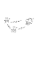
第一の実施例では、3つのステーション(STA)がアドホックネットワークを形成する際の例として、プリンタ103が形成したアドホックネットワークに対してデジタルカメラ101とデジタルカメラ102が参加する例を説明する。図1に本実施形態の機器間接続形態を示す。デジタルカメラ同士は無線インターフェースを介して画像を転送することが可能であり、またプリンタはデジタルカメラから印刷要求された画像を無線インターフェースで転送し印刷することが可能である。
(First embodiment)
In the first embodiment, an example in which the
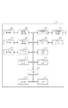
図2に、本実施形態におけるデジタルカメラの機能ブロック図を示す。ここではデジタルカメラ101とデジタルカメラ102は同じ機能ブロックをもつとしている。デジタルカメラの操作部210は、システムコントローラ211を介してCPU215に接続されており、操作部にはデジタルカメラのシャッタースイッチや各種キーが含まれる。撮像部202は、シャッターが押下されたときに画像を撮影するブロックで、撮像処理部203によって処理される。表示部206は、LCD表示、LED表示、音声表示等、ユーザに対する情報を表示するブロックであり、表示処理部207によってその表示内容の制御処理が行われる。また表示部206に表示された情報から選択するなどの操作は操作部210と連動して行われることになる。すなわち、表示部206と操作部210とがユーザインタフェースを構成することになる。
FIG. 2 shows a functional block diagram of the digital camera in the present embodiment. Here, it is assumed that the
メモリカードI/F208は、メモリカード209を接続する為のインタフェースであり、USBI/F212は、外部機器とUSBを用いて接続する為のインタフェース、オーディオI/F214は、音信号を外部機器と接続する為のインタフェースである。これらのブロック図に示される機能部分は、CPU215からの制御によって処理され、CPUによって制御されるプログラムは、ROM216、もしくは、フラッシュROM213に格納されることになる。また、CPU215によって処理されるデータは、RAM217、もしくは、フラッシュROM213に対して、書き込み、読み込みが行われる。フラッシュROM213は不揮発性の記憶領域である。なお、撮像した画像データは公知の圧縮処理を経てメモリカードI/F208を介し、メモリカード209に書き込まれる(保存される)。
The memory card I / F 208 is an interface for connecting the
無線通信RF部205と無線通信コントローラ部204を合わせて無線インターフェースが構成される。無線通信RF部205では、アンテナから受信したアナログ信号をデジタル化し、逆にデジタル情報をアナログ化してアンテナより送信するためのハードウェアブロックが存在する。無線通信コントローラ部204は、通信を制御するMAC層とそれらを駆動させるファームウェアを処理するハードウェアより構成される。無線通信コントローラ部204にはフラッシュROMが内蔵されており、MACアドレスなどを記憶することが可能である。
The wireless
これらのブロック図に示される機能部分は、CPU215からの制御によって処理され、CPU215によって制御されるプログラム(ドライバ)は、ROM216、もしくは、フラッシュROM213に格納されることになる。ファームウェアは、無線通信コントローラ部204内に存在するフラッシュROMなどに格納されているか、もしくはデジタルカメラ201側が保持するフラッシュROM213もしくはROM216に格納されており、無線インターフェースを利用する際に無線通信コントローラ204にロードされる仕組みであってもよい。またフラッシュROM213には、無線通信に必要なネットワーク識別子のESSIDや暗号鍵などのパラメータが格納されており、無線インターフェースを利用する際に、ドライバが無線通信コントローラにこれらの値を引き渡すことで無線通信が可能となる。
The functional parts shown in these block diagrams are processed by control from the CPU 215, and a program (driver) controlled by the CPU 215 is stored in the
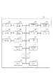
図3に示すのが、本実施形態におけるプリンタの機能ブロック図である。プリンタ301の操作部310は、システムコントローラ311を介してCPU315に接続されている。プリントエンジン302は、実際に用紙に画像をプリントする機能ブロックであり、プリント処理部303によって処理される。プリントエンジンは如何なるものでも良いが、本実施形態では図1で使われているプリンタ103は主に家庭で使われている熱エネルギーによってインク液滴を記録紙等の記録媒体上に吐出するインクジェットプリンタとした。
FIG. 3 is a functional block diagram of the printer in this embodiment. The
表示部306は、LCD表示、LED表示、音声表示等、ユーザに対する情報を表示するブロックであり、表示処理部307の制御によりその表示内容が制御される。また表示部306に表示された情報から選択するなどの操作は操作部310を介して行われる。つまり、表示部306及び操作部310が実施形態におけるプリンタ301のユーザI/Fとなる。
The
メモリカードI/F308は、脱着可能なメモリカード309を接続する為のインタフェースであり、デジタルカメラに搭載されたメモリカードを差し込むことで、撮像画像を印刷することも可能にしている。
The memory card I /
USBI/F312は、外部機器とUSBを用いて接続する為のインタフェース、ETHERI/F314は、外部機器とETHER通信を用いて接続する為のインタフェースである。これらのブロック図に示される機能部分は、CPU315からの制御によって処理され、CPU315によって制御されるプログラムは、ROM316、もしくは、フラッシュROM313に格納され、CPU315によって処理されるデータは、RAM317、もしくは、フラッシュROM313に対して、書き込み、読み込みが行われる。フラッシュROM313は不揮発性の記憶領域である。
The USB I /
無線通信RF部305と無線通信コントローラ部304を合わせて無線インターフェースが構成される。無線通信RF部305では、アンテナから受信したアナログ信号をデジタル化し、逆にデジタル情報をアナログ化してアンテナより送信するためのハードウェアブロックが存在する。無線通信コントローラ部304は、通信を制御するMAC層やそれらを駆動させるファームウェアを処理するハードウェアより構成される。無線通信コントローラ部304にはフラッシュROMが内蔵されており、MACアドレスなどを記憶することが可能である。
The wireless
これらのブロック図に示される機能部分は、CPU315からの制御によって処理され、CPU315によって制御されるプログラム(ドライバ)は、ROM316、もしくは、フラッシュROM313に格納されることになる。ファームウェアは、無線通信コントローラ部304内に存在するフラッシュROMなどに格納されているか、もしくはプリンタ301側が保持するフラッシュROM313もしくはROM316に格納されており無線インターフェースを利用する際に無線通信コントローラ304にロードされる仕組みであってもよい。またフラッシュROM313には、無線通信に必要なネットワーク識別子であるESSIDや暗号鍵などのパラメータが格納されており、無線インターフェースを利用する際に、ドライバが無線通信コントローラにこれらの値を引き渡すことで無線通信が可能となる。
The functional parts shown in these block diagrams are processed by control from the
以上、実施形態におけるデジタルカメラ101、102とプリンタ103のそれぞれの構成について説明した。なお、無線通信RF部205、305にはアンテナが設けられるが、外部に突出する形態で有するものとは限らない。特に、デジタルカメラの場合、携帯性が重要なファクタであるから、アンテナは外部に突出するのではなく、内蔵もしくは表面上に実装されることが望ましい。
The configurations of the
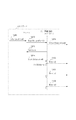
第一の実施形態では、プリンタ103がアドホックネットワークを形成し、デジタルカメラ101およびデジタルカメラ102の順でネットワークに参加する。そして、デジタルカメラ102およびプリンタ103の順でパワーセーブモードに移行する。まずプリンタ103の動作手順について図4を用いて説明する。
In the first embodiment, the
図4は、プリンタ103のデバイスドライバと無線通信コントローラ304の間のコマンドシーケンスと、またそれらコマンドを無線通信コントローラ304と無線通信RF部305で処理した結果、エアー上にだされるフレームシーケンスを時間軸とともに図示したものである。
FIG. 4 shows a command sequence between the device driver of the
プリンタ103のCPU315により動作するアプリケーションプログラムからデバイスドライバに対し、ESSIDを指定してアドホックネットワークに参加する要求が発行される(S401)。ここではESSIDをSaveNetとした。ドライバは、ESSIDにSaveNetをもつアドホックネットワークが存在するかどうか確認するためにスキャンを行う。スキャンは、無線通信コントローラ304に対して一連のコマンドを発行することで行われる(S402)。
A request to join the ad hoc network with the ESSID specified is issued from the application program operated by the
その後、それらのコマンドは無線通信コントローラ304と無線通信RF部305で処理されProbe Requestがエアー上に送信される(S403)。しかし、ネットワーク上にはSaveNetのESSIDで運用されているステーション(STA)がないため何も応答が返ってこない。無線通信コントローラ304は、ある一定期間何も応答がないとタイムアウトをして、その旨をドライバに通知する(S404)。次に、ドライバはESSIDがSaveNetのアドホックネットワークを生成する一連のコマンドを無線通信コントローラ304に対して発行する(S405)。この際に、プリンタ103のCPU315はパワーセーブモードを利用可能にするための変数であるATIM Windowを正の値(かつビーコン間隔よりもかなり小さい値)に指定する。S405の設定が終了すると、周期的にビーコンが転送されるようになる。
Thereafter, these commands are processed by the
IEEE802.11規格では、ビーコンが送信もしくは受信された直後、このATIM Window期間だけはそのネットワークに参加しているSTAは常に起きている(Awake状態)必要がある。また、このATIM Window期間中に送信してよいパケットの種類には限定があり、コントロールフレーム(RTS(Request To Send)、CTS、ACKなど)とマネージメントフレーム(Probe Request、ATIM(Announcement Traffic Indication Message)など)のみが許されている。 According to the IEEE802.11 standard, immediately after a beacon is transmitted or received, STAs participating in the network need to always wake up (Awake state) only during this ATIM Window period. In addition, there are limitations on the types of packets that can be transmitted during this ATIM Window period, and control frames (RTS (Request To Send), CTS, ACK, etc.) and management frames (Probe Request, ATIM (Announcement Traffic Indication Message)) Only) is allowed.
図5に、ビーコン(S406〜408)期間中にプリンタ103の無線インターフェースで消費される電流値と時間の関係を示す。この図よりビーコンを送信した後にATIM Window期間があることも分かる。プリンタ103はアクティブモードであるため、通常でも待機中の電力値がある程度必要である。またパケット送受信には大きな電流を必要とするため、ビーコン送信に大きな電流値が必要となる。
FIG. 5 shows the relationship between the current value consumed by the wireless interface of the
次に、デジタルカメラ101がプリンタ103の生成したアドホックネットワークに参加する手順について図6をもとに説明する。デジタルカメラ101のCPU215により動作するアプリケーションプログラムからデバイスドライバに、ESSIDにSaveNetをもつアドホックネットワークに参加する要求が発行される(S601)。ドライバは、SaveNetが存在するかどうか確認するためにスキャンを行う。スキャンは、無線通信コントローラ204に対して一連のコマンドを発行することで行われる(S602)。その後、それらのコマンドは無線通信コントローラ204と無線通信RF部205で処理され、Probe Requestがエアー上に送信される(S603)。
Next, a procedure for the
既に、プリンタ103がESSIDにSaveNetを指定してアドホックネットワークを形成しているので、プリンタ103よりProbe Responseが返される(S604)。無線通信コントローラ204はProbe Responseで得られた情報をドライバに渡す(S605)。この結果より、ドライバは既にESSIDがSaveNetのアドホックネットワークが存在することを認識し、このアドホックネットワークに参加する一連のコマンドを無線通信コントローラ204に対して発行する(S606)。S606の設定が終了すると、ある一定周期でプリンタ103とデジタルカメラ101のどちらかがビーコンを転送するようになる(S607)。
Since the
デジタルカメラ101は、プリンタ103が指定したATIM Windowに従った動作を行うため、ビーコンを送信もしくは受信すると、その直後のATIM Window期間中は、たとえパワーセーブモードに移行していたとしてもAwake状態を維持する。デジタルカメラ101から、プリンタ103に対してプリントデータを送信する場合は、このATIM Window期間の後である必要があり、S608〜S613はデータ送信とそれに対するACKの様子の示している。
Since the
次に、デジタルカメラ102がプリンタ103のSaveNetに参加し、その後パワーセーブモードに以降する手順について図7を用いて説明する。プリンタ103が生成したアドホックネットワークに参加するまでの手順は、S601〜S606までと全く同様であるため図7では省略している。SaveNetへ参加したのち、デジタルカメラ102のアプリケーションプログラムより、パワーセーブモードへ移行したいという要求がドライバに伝えられる(S701)。ドライバは、無線通信コントローラ204に対してパワーセーブモードに移行するための一連のコマンドを発行する(S702)。無線通信コントローラ204では、これらのコマンドを受理すると、次のビーコンタイミングまで処理をブロックする。そして、次のビーコンを受信したのち(S703)、ATIM Window期間内でパワーセーブモードに移行する旨を伝えるATIMパケットをブロードキャストで送信する(S704)。
Next, a procedure in which the
この時のATIMパケットのフレームフォーマットを図8の801に示す。このATIMパケットの送信先アドレス(DA)はブロードキャストアドレス(もしくは全てのSTAが受信可能なマルチキャストアドレス)とする。送信元アドレス(SA)は、デジタルカメラ102の無線インターフェースが持っているMACアドレスを用いる。BSSIDには、プリンタ103がアドホックネットワーク形成時に決定したBSSIDを入れる。このBSSIDの値は、このネットワーク上で転送される全てのビーコンで同一の値が用いられるので、ビーコン1(S703)などから獲得することが可能である。Frame Controlの更に詳細なフォーマットを802に示す。ATIMパケットでは、controlビットは00でsubtypeフィールドは1001となることが決まっている。また、ここではPwrMgt(PM)ビットを1にすることで、パワーセーブモードをオンにしたことを伝達する。
The frame format of the ATIM packet at this time is indicated by 801 in FIG. The destination address (DA) of this ATIM packet is a broadcast address (or a multicast address that can be received by all STAs). As the source address (SA), a MAC address possessed by the wireless interface of the
これにより、デジタルカメラ102はアドホックネットワーク上に存在する全てのSTA(プリンタ103とデジタルカメラ101)に対して、パワーセーブモードに遷移したことを伝達することが可能になり、無線通信コントローラ204からOKという結果が上位のアプリケーションまで伝達される(S705、S706)。
As a result, the
次に、プリンタ103がデジタルカメラ102に対してパワーセーブモードに移行することを伝達する際の処理について説明する。プリンタ103は、パワーセーブモードに移行する場合には、上述したデジタルカメラ102と同様に、PMビットを1に設定したATIM パケットをATIM Window期間内にブロードキャストする。無線通信コントローラ204が、ATIM Window期間中にブロードキャストのATIMパケットを受け取ると(S709)、割り込みでイベントを発行させドライバに対してあるSTAが電力モードを変更した旨を伝える(S710)。
Next, processing when the
ドライバでは、図10に示すような現在パワーセーブモードにあるSTAのMACアドレスを示すパワーセーブリスト1001が保存されることになっている。デジタルカメラ102において、S710で STAの電力モード変更を受け取る以前は登録されているMACアドレスは一つもなく、STAの電力モード変更の受信によりプリンタ103のMACアドレスが登録される。
The driver is to store a
またMACアドレスに付随する情報として期限切れ時間も合わせて記憶する。期限切れ時間は、ある一定周期でデクリメントされ0になると対応するMACアドレスがパワーセーブリスト1001から削除される仕組みになっている。期限切れ時間は、もしプリンタ103が突然の異常で停止してしまって無線通信ができなくなった場合や、電波が届かない場所に移動してしまった場合などに不要な情報をいつまでも保持する必要がないようにつけられている。
The expiration time is also stored as information accompanying the MAC address. The expiration time is decremented at a certain period and becomes 0, so that the corresponding MAC address is deleted from the
ドライバはS710でSTAの電力モード変更を受信して、パワーセーブリスト1001への登録を終えたのち、プリンタ103がパワーセーブモードになったことを無線通信コントローラ204に通知するコマンド(S711)を発行する。このコマンドはプリンタ103のMACアドレスを必要とし、これ以後無線通信コントローラ204では、ドライバよりプリンタ103のMACアドレス向けに送信されるデータを渡されたとき、そのデータ送信に先立ちATIMパケットをプリンタ103向けにユニキャストで送信するようになる。
The driver receives the STA power mode change in S710, and after completing registration in the
S712でデジタルカメラ102のCPU215からデータ送信要求がドライバに渡され、S713で無線通信コントローラ204に対するコマンドに変換され発行される。無線通信コントローラ204はこれらを受理し、そのパケットの宛先アドレスがS711で登録されたMACアドレスであることを確認すると、ビーコン(S714)の受信または送信時間を待つ。ビーコンの受信または送信が終了すると、ATIM Window期間内でプリンタ103に対してユニキャストのATIMパケットを送信する(S715)。プリンタ103は、このATIMパケットを受信すると、ACKを返し(S716)、そのビーコン期間中はAwakeモードに遷移するため、S717のデータパケットを受信でき、ACKを返戻する(S718)。S719とS720を経由してデータが正しく送信される。
In S712, a data transmission request is passed from the CPU 215 of the
次にプリンタ103がパワーセーブからアクティブモードに遷移する要求をだすときの手順について述べる。プリンタ103は、ブロードキャスト(もしくは全てのSTAが受信可能なマルチキャスト)のATIMパケットを使い、PwrMgtビットを0にして送信する(S723)。このパケットは、ネットワーク中の全てのSTAが受信でき同じ処理を行うが、代表してデジタルカメラ102の動作として説明する。
Next, a procedure when the
S723でこのATIMパケットを受信すると、デジタルカメラ102の無線通信コントローラ204は割り込みでイベントを発行させ、ドライバに対してプリンタ103のMACアドレスとPMビットの値を通知する(S724)。ドライバでは、PMビットが0になっていることを確認し、パワーセーブリスト1001からプリンタ103のMACに対応する項目を削除する。また、もしパワーセーブリスト1001に登録されていないMACアドレスが送信されてきた場合は無視をする。
When the ATIM packet is received in S723, the
その後、プリンタ103のMACアドレスがアクティブモードになったことを通知するコマンドが無線通信コントローラ204に発行される(S725)。これにより、無線通信コントローラ204では、このMACアドレス宛てに送信するデータについて、ATIMパケットを送信する必要をなくし、すぐに転送するようになる。
Thereafter, a command for notifying that the MAC address of the
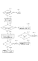
パワーセーブリスト1001への登録および削除のアルゴリズムを図11に示す。ATIM Window期間中にブロードキャストのATIMパケットを受信する(S1101)と、ATIMパケット中のMACアドレスとPMビットの情報をドライバへ通知する(S1102)。もしPMビットが1であるときは、送信元がパワーセーブモードへ移行することを意味する。S1103でPMビットが1であるかを確認し、もし1であればパワーセーブリスト1001に存在するかどうかを確認する。もし、パワーセーブリスト1001に存在すれば、期限切れ時間を初期値に設定する(S1112)。もし存在しない場合は、MACアドレスと期限切れ時間をパワーセーブリスト1001に登録する(S1105)。その後、無線通信コントローラにMACアドレスを通知し、そのMACアドレスを無線通信コントローラに登録する(S1110)。
FIG. 11 shows an algorithm for registration and deletion in the
S1103でPMビットが1でない、つまり、0の場合は、送信元がアクティブモードへ移行することを意味する。S1106で通信されたMACアドレスがパワーセーブリスト1001に存在するかを確認し、もし存在すればS1107で対応するMACアドレスの項目を削除する。そして、無線通信コントローラからMACアドレスを削除する(S1111)。存在しない場合は、何もせずに終了する(S1109)。
If the PM bit is not 1 in S1103, that is, 0, it means that the transmission source shifts to the active mode. It is checked whether the MAC address communicated in S1106 exists in the
期限切れ時間をどのように利用するかは、いくつかの方法がある。最も単純には、パワーセーブを継続する最大時間を規定し、各STAはその最大時間内に一度はそのときの電力モードの状態を通知するブロードキャストのATIMパケットを送信する方法である。図11のアルゴリズムにより、PMビットがセットされたブロードキャストATIMパケットが受信されるたびに期限切れ時間が初期値に設定される。 There are several ways to use the expiration time. The simplest method is to define a maximum time for continuing the power save, and each STA transmits a broadcast ATIM packet that notifies the state of the current power mode once within the maximum time. According to the algorithm of FIG. 11, the expiration time is set to the initial value every time a broadcast ATIM packet with the PM bit set is received.
また、ブロードキャストATIMを検知する以外に、パワーセーブリスト1001に存在するMACアドレスから何かデータを受信したかを検知して期限切れ時間を初期値に戻してもよい。この場合は電力モードを通知するブロードキャストATIMを送信する無駄が省ける。
In addition to detecting the broadcast ATIM, it may be detected whether any data is received from the MAC address existing in the
以上の実施形態では、ブロードキャストのATIMパケットを受信してから、受信した旨をドライバに通知して(S710及びS724)、パワーセーブリストへの登録と削除を行っていた。他の実施形態としては、これら手続きを無線通信コントローラ204内部で実行しても構わない。
In the above embodiment, after receiving the broadcast ATIM packet, the driver is notified of the reception (S710 and S724), and registration and deletion are performed in the power save list. As another embodiment, these procedures may be executed inside the
ここでパワーセーブモードと、ブロードキャストATIMを送受信した場合の消費電力の効果を見るために、図9に、図7のビーコン1〜5の期間中にデジタルカメラ102の無線インターフェースで消費される電流値と時間の関係を示す。電力の消費レベルには、待機中と受信中と送信中、さらに、パワーセーブ中にATIM Window期間終了後に遷移するSleep状態中(doze状態)の4つレベルがある。ここでは送信のほうが受信よりも大きな電力が必要であり、またSleep状態ではほとんど電流は必要ないとして図示している。また、IEEE802.11の規格では、ATIMパケットを送信もしくは受信したときは、そのビーコン期間が終了するまではAwake状態を維持する必要がある。
Here, in order to see the effect of power consumption when the power save mode and broadcast ATIM are transmitted and received, FIG. 9 shows the current value consumed by the wireless interface of the
図9において、ビーコン1を受信したのちに、ブロードキャストATIM(S703)を送信して、パワーセーブモードに移行する。ただし、このビーコン1の周期が終わるまではAwake状態を維持する必要がある。ビーコン2を受信し、更にATIM Window期間が経過した後に、Sleep状態に移行する。ATIM Window期間はAwake状態に遷移しなければならないため、ビーコン3のあとにAwake状態に遷移し、プリンタ103からのブロードキャストATIM(S709)を受信する。ビーコン4のあとでは、プリンタ103にデータを送信するためにATIMパケットをプリンタ103に送信し(S715)、ATIM Windowが終了したあとにデータを送信し(S716)、ACKを受信する(S717)。ビーコン6のあとでは、プリンタからアクティブモードへ遷移するためのブロードキャストATIMパケットを受け取る(S723)ので、このビーコン期間が終了するまではAwake状態を維持する。
In FIG. 9, after receiving the
以上示したように、電力モードの変更をする際はATIMパケットをブロードキャストで送信し、また相手の電力モードを管理するためにはブロードキャストATIMパケットのPMビットをチェックすることで行った。 As described above, when changing the power mode, the ATIM packet is broadcasted, and in order to manage the power mode of the other party, the PM bit of the broadcast ATIM packet is checked.
これにより、相手の電力モードが分からずに、通信相手がSleep状態にあるときにデータを送信してしまうことを防ぐことができる。もし相手がSleep状態にある場合に、送信をしてしまうと全てパケットロスとなるためこの効果は大きい。 As a result, it is possible to prevent data from being transmitted when the communication partner is in the sleep state without knowing the power mode of the partner. If the other party is in the sleep state, if transmission is performed, all packets are lost, so this effect is great.
また、ブロードキャストATIMで電力モードの切り換え通知が行われることより、ネットワークの全てのSTAが、どのSTAがパワーセーブモードになっているかを容易に把握することが可能となり、また、全てSTAに電力モードの切り替えを通知することもできる。 In addition, since the power mode switching notification is performed by the broadcast ATIM, all STAs in the network can easily grasp which STA is in the power saving mode, and all the STAs are in the power mode. It is also possible to notify the switching.
さらにアドホックネットワークでは、接続の際に特別なパケットを送信しないので、誰がネットワーク上に参加したかを判断するのは非常に難しい(アドホックモードでは、接続時はアクティブモードで接続する必要がある)という問題がある。本実施形態では、パワーセーブモードになったSTAのみを各STAがパワーセーブリストとして管理し、アクティブなSTAの情報は保持していない。この管理方法により、何台のSTAがネットワーク上に存在するのかを厳格に管理する必要がないという利点もある。 Furthermore, in ad hoc networks, no special packets are sent when connecting, so it is very difficult to determine who has joined the network (in ad hoc mode, it is necessary to connect in active mode) There's a problem. In this embodiment, each STA manages only the STAs in the power save mode as a power save list, and does not hold information on active STAs. This management method also has an advantage that it is not necessary to strictly manage how many STAs exist on the network.
また、不意の障害や電波環境の変化、移動に伴う電波切断などによる状態の不一致を避けるために、パワーセーブリストには期限切れ時間を付加したことでロバスト性を高めることができるという利点もある。 In addition, there is an advantage that the robustness can be enhanced by adding an expiration time to the power save list in order to avoid a state mismatch due to an unexpected failure, a change in radio wave environment, a radio wave disconnection due to movement, and the like.
(第二の実施形態)
第一の実施形態では、ATIM Window期間中はアドホックネットワーク内の全てのSTAがAwake状態であることを利用して、ATIMパケットをブロードキャストすることにより電力モード変更の通知を行った。しかしこの方法では、全てのSTAがATIMパケットを受信することになり、パワーセーブモードのSTAもそのビーコン期間中でAwake状態になる必要があるため消費電力が無駄になっている。
(Second embodiment)
In the first embodiment, the power mode change is notified by broadcasting the ATIM packet by using the fact that all the STAs in the ad hoc network are in the Awake state during the ATIM Window period. However, in this method, all STAs receive the ATIM packet, and the power saving mode STAs also need to be in the awake state during the beacon period, so power consumption is wasted.
アドホックネットワーク中に存在するSTAの中でも、STAの電力モードを知る必要があるのは、パケットを送信するSTAのみであり、もしその送信相手以外のSTAに対して何も通信をしないのであれば特に相手以外の電力モードを気にする必要はない。 Of the STAs existing in the ad hoc network, it is only the STA that transmits the packet that needs to know the power mode of the STA, especially if no communication is performed with the STA other than the transmission partner. There is no need to worry about power modes other than the other party.
一般にアプリケーションプロトコルでは、通信相手とコネクションを確立し、その相手と専属的に通信を行ってからコネクションを終了する。つまり、通信相手が確定するとその後ある期間はその二者間で通信を行うが、コネクションを確立していない他のSTAとはほとんど通信がない。第二の実施形態では、どのSTA間で通信が行われるかを明示的にドライバや無線通信コントローラに指示することで、その二者間でのみ電力モードの遷移通知を行うことを可能にする。 In general, in an application protocol, a connection is established with a communication partner, and after the exclusive communication with that partner, the connection is terminated. That is, when a communication partner is determined, communication is performed between the two parties for a certain period thereafter, but there is almost no communication with other STAs that have not established a connection. In the second embodiment, by explicitly instructing the driver and the wireless communication controller which STA is to communicate, it is possible to notify the transition of the power mode only between the two parties.
第二の実施形態も第一の実施形態と同様に、プリンタ103がアドホックネットワークを形成し、デジタルカメラ101およびデジタルカメラ102の順でネットワークに参加する。そして、デジタルカメラ102、プリンタ103の順でパワーセーブモードになる。
In the second embodiment, as in the first embodiment, the
プリンタ103がESSIDをSaveNetとしてアドホックネットワークする手順は図4と同様であり、デジタルカメラ101がSaveNetに参加する手順も図6と同様なため割愛する。
The procedure in which the
デジタルカメラ102がSaveNetに参加する手順は図6のS601からS606と同様であり、その後の処理について図12を用いながら説明する。デジタルカメラ102のCPU215により動作するアプリケーションプログラムは、TCPなどのコネクション確立を行うことで通信を開始するため、コネクション確立前に相手のMACアドレスをドライバに対して通知する(S1201)。このタイミングは使用する通信プロトコルに依存し、TCPのコネクションを二つ利用するFTPなどではセッションの確立の前(はじめのTCPコネクションが開始される時)に行えばよい。
The procedure for the
S1201により、ドライバが通信相手となるMACアドレスを獲得したら、第一の実施形態で利用したパワーセーブリスト1001の代わりにコミュニケーションリスト1301を用いる(図13)。パワーセーブリスト1001と異なるのは、このリストは通信相手の一覧を示すものであり、パワーセーブモードにあるSTAのみだけでなくアクティブモードのSTAも管理することにある。S1201でプリンタ103のMACアドレスが通知されると、その電力モードの値としてアクティブモードと、期限切れ時間の初期値が登録される。期限切れ時間は、第一の実施形態と同様に、もしプリンタが突然の異常で停止してしまって無線通信ができなくなった場合や、電波が届かない場所に移動してしまった場合などに不要な情報をいつまでも保持する必要がないように利用される。
When the driver obtains the MAC address to be a communication partner in S1201, the
コミュニケーションリスト1301への登録が完了すると、デジタルカメラ102のアプリケーションプログラムより、パワーセーブモードへ移行したいという要求がドライバに伝えられる(S1202)。ドライバは、無線通信コントローラ204に対してパワーセーブモードに移行するための一連のコマンドを発行する(S1203)。無線通信コントローラ204では、これらのコマンドを受理すると次のビーコンタイミングまで処理をブロックする。そして、次のビーコンを受信したのち(S1204)、コミュニケーションリストに存在する全てのMACアドレスに対して、ATIM Window期間内にパワーセーブモードに移行する旨を伝えるATIMパケットをユニキャストで送信する。第二の実施形態においてはプリンタ103のみにATIMパケットが送信される(S1205)。そして、ATIMパケットはユニキャストなので、ACKが返戻される(S1206)。
When registration in the
このときのATIMパケットのフレームフォーマットを図8の801で説明する。このATIMパケットの送信先アドレス(DA)はプリンタ103のMACアドレスとする。送信元アドレス(SA)は、デジタルカメラ102の無線インターフェースが持っているMACアドレスを用いる。BSSIDには、プリンタ103がアドホックネットワーク形成時に決定したBSSIDを入れる。このBSSIDの値は、このネットワーク上で転送される全てのビーコンで同一の値が用いられるので、ビーコン(S1204)などから獲得することが可能である。Frame Controlの更に詳細なフォーマットを802に示す。ATIMパケットでは、controlビットは00でsubtypeフィールドは1001となることが決まっている。また、ここではPwrMgt(PM)ビットを1にすることで、パワーセーブモードをオンにしたことを伝達する。
The frame format of the ATIM packet at this time will be described with reference to 801 in FIG. The transmission destination address (DA) of this ATIM packet is the MAC address of the
これにより、デジタルカメラ102はプリンタ103に対して、パワーセーブモードに遷移したことを伝達することが可能になり、無線通信コントローラ204からOKという結果が上位のアプリケーションまで伝達される(S1207、S1208)。
As a result, the
次に、プリンタ103がデジタルカメラ102に対してパワーセーブモードに移行することを伝達する際の処理について説明する。プリンタ103は、パワーセーブモードに移行する際に、プリンタ103が管理するコミュニケーションリストに存在するデジタルカメラ102のMACアドレスに対してPMビットが1に設定されたATIMパケットを送信する。無線通信コントローラ204が、ATIM Window期間中にユニキャストのATIMパケットを受け取ると(S1209)、割り込みでイベントを発行させドライバに対してあるSTAが電力モードを変更した旨を伝える(S1211)。
Next, processing when the
ドライバでは、S1211に付随して通知されるMACアドレスとPMビットの情報より、コミュニケーションリスト1301を更新する。まずコミュニケーションリスト1301に対応するMACアドレスが存在するか確認する。もし存在しない場合は、通知されたPMビットから電力モードを判定し、判定した電力モード、期限切れ時間を通知されたMACアドレスに対応付けてコミュニケーションリスト1301に登録する。次に、コミュニケーションリスト1301に、対応するMACアドレスが存在し、通知されたPMビットが1である場合は、コミュニケーションリスト1301のMACアドレスに対応する電力モードの値をパワーセーブモードにする。またPMビットが0である場合はアクティブモードにする。どちらの場合においても、期限切れ時間は初期値に戻す。期限切れ時間をどのように利用するかは、いくつかの方法があり第一の実施形態と同じような方法で利用できる。
The driver updates the
コミュニケーションリスト1301の電力モードの値がアクティブモードからパワーセーブモードに移行する場合は、プリンタ103がパワーセーブモードになったことを無線通信コントローラ204に通知するコマンド(S1212)を発行する。このコマンドはプリンタ103のMACアドレスを必要とし、これ以後無線通信コントローラ204では、ドライバよりプリンタ103のMACアドレス向けに送信されるデータを渡されたとき、そのデータ送信に先立ちATIMパケットをプリンタ103向けにユニキャストで送信するようになる。
When the value of the power mode in the
つまり、S1213でデジタルカメラ102からデータ送信要求がドライバに渡され、S1214で無線通信コントローラ204に対するコマンドに変換され発行されると、無線通信コントローラ204はこれらを受理し、データの送信宛先が登録されたMACアドレスである場合はビーコン(S1215)の受信または送信時間を待つ。ここでは、デジタルカメラ102は、ビーコンを送信する番なので、ビーコンを送信すると(S1215)、ATIM Window期間内でプリンタ103に対してユニキャストのATIMパケットを送信する(S1216)。この時もPMビットを1にしてATIMパケットを送信することに注意する。その後ACKを返戻する(S1217)。プリンタ103はATIMパケットを受信すると、そのビーコン期間中はAwakeモードに遷移するため、S1218のデータパケットを受信でき、ACKを返戻する(S1219)。S1220とS1221を経由してデータが正しく送信される。
In other words, when a data transmission request is passed from the
次にプリンタ103がパワーセーブモードからアクティブモードに遷移する要求をだすときの手順について述べる。プリンタ103は、ユニキャストのATIMパケットを使い、PMビットを0にして送信する。
Next, a procedure when the
S1223でこのATIMパケットを受信すると、無線通信コントローラ204は割り込みでイベントを発行させ、ドライバに対してプリンタ103のMACアドレスとPMビットの値を通知する(S1225)。ドライバは、コミュニケーションリスト1301に、対応するMACアドレスが存在するか確認する。もし存在しない場合は、通知されたPMビットから電力モードを判定し、判定した電力モードと、期限切れ時間を無線通信コントローラ204から通知されたMACアドレスに対応付けてコミュニケーションリスト1301に登録する。MACアドレスが存在し、通知されたPMビットが0の場合は、コミュニケーションリスト1301のプリンタ103のMACアドレスに対応する電力モードがパワーセーブかを確認し、もしパワーセーブであればアクティブに変更し、無線通信コントローラ204に対して登録してあるMACアドレスを解除するように要求をだす(S1226)。もし既にアクティブである場合は無視をする。これにより、無線通信コントローラ204では、このMACアドレス宛てに送信するデータについて、ATIMパケットを送信する必要をなくし、すぐに転送するようになる。
When the ATIM packet is received in S1223, the
アプリケーションのデータ転送が終了し、コミュニケーションリスト1301から対応するMACアドレスの項目を削除したい場合は、CPU215は、その要求をドライバに対して要求する(S1227)。この際に、もしそのMACアドレスの電力モードの値がパワーセーブモードである場合は、無線通信コントローラ204に対して無線通信コントローラ204に登録されている対応MACアドレスを削除するように要求する。この例の場合は、プリンタ103は既にアクティブモードになっているのでその必要はない。
When the application data transfer is completed and it is desired to delete the corresponding MAC address item from the
図14から図16にかけて、コミュニケーションリスト1301に対する登録と削除に関するアルゴリズムを示す。図14は、アプリケーションからコミュニケーションリスト1301に登録を行う場合のフローチャートである。S1401において、CPU215により動作するアプリケーションから、通信相手のMACアドレスを指定してコミュニケーションリスト1301への登録要求が発行される。S1402で、そのMACアドレスがコミュニケーションリスト1301に存在するかを確認する。もし既に存在する場合は何もしない(S1404)。存在しない場合は、MACアドレスおよび電力モードの値をアクティブモードにし、期限切れ時間を初期値に設定する(S1403)。
FIGS. 14 to 16 show algorithms relating to registration and deletion with respect to the
次に、アプリケーションからコミュニケーションリスト1301に登録されているリスト内容の削除要求が発行されたときのアルゴリズムを図16で説明する。S1601で、MACアドレスを指定してコミュニケーションリスト1301からの削除要求が発行される。S1602で、指定されたMACアドレスがコミュニケーションリスト1301に存在するかを確認する。もし存在しない場合は何もしない(S1604)。存在する場合は、電力モードの値がパワーセーブモードかを調べる(S1603)。パワーセーブモードである場合は、対応するMACアドレスを無線通信コントローラ204が管理しているデータ通信前にATIMパケットを送信するMACアドレスリストから削除する要求を、無線通信コントローラ204に発行する(S1605)。そしてコミュニケーションリスト1301からそのMACアドレスを削除する(S1606)。S1603でパワーセーブモードでない場合は、コミュニケーションリスト1301から対応するMACアドレスを削除する(S1606)。
Next, an algorithm when a request to delete list contents registered in the
また、アドホックネットワーク中のSTAからユニキャストATIMを受信した場合の処理について図15を用いて説明する。S1501で無線インターフェースがユニキャストATIMを受信すると、無線通信コントローラは、送信元のMACアドレスとフレーム中のPMビットをドライバに通知する(S1502)。ドライバでは、通知されたMACアドレスがコミュニケーションリスト1301に存在するかを確認する(S1503)。もし存在する場合は、そのMACアドレスに対応する期限切れ時間の値を初期値に戻す(S1509)。次に伝達されたPMビットから、パワーセーブモードへ移行すると判断された場合(PMビットが1で、かつ以前の電力モードの値がアクティブモード)、無線通信コントローラに対してそのMACアドレスを登録する(S1511)。もし、アクティブモードへの遷移もしくは、既にパワーセーブモードに移行していた場合に関してはないも行わない(S1512)。 Also, processing when a unicast ATIM is received from an STA in an ad hoc network will be described with reference to FIG. When the wireless interface receives the unicast ATIM in S1501, the wireless communication controller notifies the driver of the source MAC address and the PM bit in the frame (S1502). The driver checks whether the notified MAC address exists in the communication list 1301 (S1503). If it exists, the expiration time value corresponding to the MAC address is returned to the initial value (S1509). Next, when it is determined from the transmitted PM bit to shift to the power saving mode (PM bit is 1 and the previous power mode value is the active mode), the MAC address is registered to the wireless communication controller. (S1511). If there is no transition to the active mode or if the power saving mode has already been entered, no action is taken (S1512).
S1503において、指定されたMACアドレスがコミュニケーションリスト1301に登録されてない場合は、MACアドレスに対応させて、PMビットの値に対応する電力モードと、期限切れ時間を登録する(S1504)。もしこのとき、PMビットが1である場合は、無線通信コントローラ204に対してこのMACアドレスを登録するようにコマンドを発行する(S1506)。PMビットが0の場合は何もおこなわない(S1508)。
In S1503, if the designated MAC address is not registered in the
以上の実施形態では、コミュニケーションリストへの登録手段(S1201)と、パワーセーブを有効にする手段(S1202)を分離して書いてが、パワーセーブを有効にする時点(S1202)で、どのSTA宛て(複数可)にその通知を出すかを指定しても同様の効果を得ることができる。また、コミュニケーションリストからそれらの機器情報を削除するのは、パワーセーブモードからアクティブモードへの変更要求があるときか、もしくは各機器に付帯された期限付き時間が過ぎた時に行ってもよい。 In the above embodiment, the means for registering in the communication list (S1201) and the means for enabling the power save (S1202) are written separately, but to which STA at the time of enabling the power save (S1202) The same effect can be obtained by designating whether or not to issue the notification to (multiple). The device information may be deleted from the communication list when there is a request to change from the power save mode to the active mode, or when a time limit attached to each device has passed.
さらには、データを送信する手段(S1213)に、コミュニケーションリストへの登録手段(S1201)とパワーセーブモードを有効にする手段(S1202)を兼ね合わせてもよい。データ送信があるたびにコミュニケーションリストに送信先が登録されていなければ、ATIMパケットをデータ送信に先立って送信し、その後にデータを送信してもよい。これにより、データ通信を行う相手に必ずパワーセーブモードを伝達することが可能になる。 Furthermore, the means for transmitting data (S1213) may be combined with the means for registering in the communication list (S1201) and the means for enabling the power save mode (S1202). When the transmission destination is not registered in the communication list every time data is transmitted, the ATIM packet may be transmitted prior to the data transmission, and then the data may be transmitted. As a result, the power save mode can be transmitted to the other party who performs data communication.
また以上の実施形態では、ATIMパケットを受信してから、受信した旨をドライバに通知して(S1211及びS1225)、コミュニケーションリストの電力モードを変更し、さらに無線通信コントローラに対してMACアドレスの登録(S1212)や削除(S1226)を行っていた。他の実施形態としては、これら手続きを無線通信コントローラ204内部で実行しても構わない。
In the above embodiment, after receiving the ATIM packet, the driver is notified of the reception (S1211 and S1225), the power mode of the communication list is changed, and the MAC address is registered to the wireless communication controller. (S1212) and deletion (S1226) were performed. As another embodiment, these procedures may be executed inside the
また以上の実施形態では、ATIMパケットを利用した例を述べたが、同様のことをRTSパケットでおこなうことも可能である。 In the above embodiment, the example using the ATIM packet has been described. However, the same thing can be performed using the RTS packet.
以上述べたように、第二の実施形態では第一の実施形態と比べて、通信する相手を明示的にアプリケーションから指定することによりブロードキャストATIMを受信することで生じていた、全てのSTAがAwake状態に遷移することを防ぎ、関係のある二者間でのみ電力モードの変更を伝えることができるようになった。 As described above, in the second embodiment, as compared with the first embodiment, all STAs that are generated by receiving a broadcast ATIM by explicitly specifying a communication partner from an application are all awake. It is now possible to prevent state transitions and communicate power mode changes only between the two parties involved.
(第三の実施形態)
第一および第二の実施形態では、ATIM Window中はアドホックネットワーク内の全てのSTAがAwake状態であることを利用して、ATIMパケットをブロードキャストもしくはユニキャストで送信することにより電力モードの通知を行った。この方法では、電力モードを通知する前に次のビーコンが通信されるまで待つ必要がある。ビーコン間隔は通常100ms程度に設定されているため、最悪の場合、100msは電力モードの変更を伝えることができずに制御がブロックしてしまう。
(Third embodiment)
In the first and second embodiments, the power mode is notified by broadcasting or unicasting the ATIM packet using the fact that all STAs in the ad hoc network are in the awake state during the ATIM Window. It was. In this method, it is necessary to wait until the next beacon is communicated before notifying the power mode. Since the beacon interval is normally set to about 100 ms, in the worst case, 100 ms cannot transmit the change of the power mode and the control is blocked.
第三の実施形態では、この点を改善したもので、相手の状態を検知し、もし相手がアクティブモードである場合は、次のビーコン時間を待つ必要がなく、すぐに電力モードを通知できるようにする。 In the third embodiment, this point is improved so that the state of the other party is detected. If the other party is in the active mode, the power mode can be notified immediately without waiting for the next beacon time. To.
図17に第三の実施形態のシーケンス図を示す。第二の実施形態と同様に、第一の実施形態とデジタルカメラ102がプリンタ103の生成したアドホックネットワークSaveNetに参加し、その後コミュニケーションリストへの登録(S1701)、パワーセーブモードへの移行要求を発行するところ(S1702、S1703)までは同様である。
FIG. 17 shows a sequence diagram of the third embodiment. Similar to the second embodiment, the
次に、電力モードを通知する相手がアクティブモードであるかを判断する方法について述べる。図17において、S1718でプリンタ103はビーコン送信しているため、IEEE802.11の規格にのっとり、プリンタ103はこのビーコン期間中はアクティブモードである必要がある。これらのことを無線通信コントローラ204は記憶しておき、コミュニケーションリストへの追加があった宛先がビーコンを送信した宛先と一致した場合は、すぐに電力モード通知要求をだす。
Next, a method for determining whether or not the other party that notifies the power mode is the active mode will be described. In FIG. 17, since the
この通知要求には、第一および第二の実施例で利用したATIMパケットとは異なりヌルデータパケットを用いる(S1704)。ヌルデータパケットの指定は、図8の802において、controlビットが10であり、Subtypeが0100とする。また、パワーセーブモードをオンにする場合は、PwrMgt(PM)ビットを1にし、オフにする場合は0にする。その後ACKが返戻される(S1705)と、無線通信コントローラ204からOKという結果が上位のアプリケーションまで伝達される(S1706、S1707)。
Unlike the ATIM packet used in the first and second embodiments, a null data packet is used for this notification request (S1704). The null data packet is specified by setting the control bit to 10 and the subtype to 0100 in 802 of FIG. Further, the PwrMgt (PM) bit is set to 1 when the power save mode is turned on, and is set to 0 when the power save mode is turned off. After that, when ACK is returned (S1705), the result of OK is transmitted from the
もし、S1718でプリンタ103がビーコンを送信していない場合でも、S1704でヌルパケットの送信を試みて、ACK(S1705)が返戻されることを期待してもよい。ただし、ACKの応答がない場合は、次のビーコンが受信もしくは送信されるまで待ち、プリンタ103がビーコンを送信したことを確認後にヌルパケットを送信するか、もしくはプリンタ103からのビーコンが確認できない場合は第二の実施形態で行ったようにATIMパケットをプリンタ103に送信することで、次のビーコン期間までには必ずパワーセーブ移行への要求がプリンタ103で受信可能なになるような手段を用いる。
Even if the
また、コミュニケーションリストでアクティブ状態であると管理されている相手に電力モードの変更を通知する場合は、その相手がビーコンの送信元か否かに係わらず、ビーコンを受信する前に、その相手にヌルパケットで電力モードの変更を通知してもよい。 In addition, when notifying a partner managed as active in the communication list of a power mode change before receiving a beacon, regardless of whether the partner is a beacon sender or not The change of the power mode may be notified by a null packet.
以上述べたように、第三の実施形態では第一及び第二の実施形態と比べて、もし通信相手がアクティブモードである場合は、電力モードを通知できるタイミングを早くすることが可能である。また、アクティブモードでなくても、第二の実施形態との併用で次のビーコン期間までには電力モードの通知ができる。 As described above, in the third embodiment, when the communication partner is in the active mode, the timing at which the power mode can be notified can be advanced compared to the first and second embodiments. Moreover, even if it is not an active mode, notification of an electric power mode can be performed by the combined use with 2nd embodiment by the next beacon period.
(その他の実施形態)
第1実施形態から第三の実施形態3で、IEEE802.11技術規格にそった形で説明を行ったが、同様の効果をもつ技術規格であればIEEE802.11に限らず広く適用可能である。
(Other embodiments)
In the first to third embodiments, the description has been made in accordance with the IEEE 802.11 technical standard. However, any technical standard having the same effect can be widely applied without being limited to IEEE 802.11. .
また、第一の実施形態から第3の実施形態では、アドホックネットワークに参加する全てのSTAが参加したのちに、STA(実施例ではデジタルカメラ102)は順にパワーセーブモードに遷移していく例を示した。
In the first to third embodiments, after all STAs participating in the ad hoc network have joined, the STA (the
これと異なり例えば、プリンタ103が形成したアドホックネットワークに対してデジタルカメラ101が参加したのち、すぐにパワーセーブモードになるための通知(ブロードキャストATIM、ユニキャストATIM、もしくはnullパケット)を送信し、その後にデジタルカメラ102がネットワークに参加した場合は、プリンタ103はデジタルカメラ101がパワーセーブモードになっていることを知っているが、デジタルカメラ102はその情報が送信されたあとにネットワークに加わっているため、デジタルカメラ101がパワーセーブモードであることは分からない。
Unlike this, for example, after the
このような問題を回避するために、各STAは周期的に自身の電力モードを通知しても構わない。例えば、第一の実施形態ではブロードキャストのATIMパケットを10ビーコンインターバルに一度送信するなどしてもよい。このようにすることで、あとからネットワークに参加したSTAも、相手の電力モードを獲得することが可能になる。 In order to avoid such a problem, each STA may periodically notify its own power mode. For example, in the first embodiment, a broadcast ATIM packet may be transmitted once every 10 beacon intervals. In this way, STAs that have joined the network later can also acquire the other party's power mode.
また、アドホックモードでパワーセーブを行うための運用方法として、参加すべき全てのSTAが加わった後に、各STAはパワーセーブへの移行をするようにユーザインターフェースで操作することでこれを防ぐことも可能である。 In addition, as an operation method for performing power save in the ad hoc mode, after all STAs to participate are added, each STA can be prevented from operating by operating the user interface so as to shift to power save. Is possible.
Claims (17)
電力モードを省電力モードに変更する変更手段と、
前記ネットワーク内のいずれか1つの通信装置により報知信号が送信されてから次の報知信号が送信されるまでの間の、省電力モードの他の通信装置が通信可能状態になる期間を判別する判別手段と、
前記変更手段により電力モードを省電力モードに変更する際は、前記判別手段により判別された期間に、前記ネットワーク内の他の通信装置に対して省電力モードへの変更を通知する通知手段と、
を有することを特徴とする通信装置。 A communication device in a network in which communication devices communicate directly with each other without using a relay device ,
Changing means for changing the power mode to the power saving mode ;
Discriminating to determine a period during which another communication device in the power saving mode is in a communicable state from when a notification signal is transmitted by any one communication device in the network to when the next notification signal is transmitted Means,
A notification unit when changing the power mode to the power saving mode, to the period of time that is determined by said determining means, for notifying the change to the power saving mode to other communication devices in the network by the changing means,
A communication apparatus comprising:
前記通知手段は、省電力モードへの変更をネットワーク上へブロードキャストで通知することを特徴とする通信装置。 In claim 1,
It said notification means, communication apparatus and notifies by broadcasting the change to the power saving mode to the network.
前記通知手段は、前記ネットワーク内の特定の機器に対して前記通知を行うことを特徴とする通信装置。 In claim 1,
The communication device according to claim 1, wherein the notification means notifies the specific device in the network .
前記判別手段は、IEEE802.11で定義されるATIM Window期間を判別することを特徴とする通信装置。 In claim 1,
It said discrimination means, the communication apparatus characterized by determining the ATIM Window period defined by IEEE 802.11.
前記通知手段は、ATIMパケットを用いて省電力モードへの変更を通知することを特徴とする通信装置。 In claim 1,
It said notification means, communication apparatus and notifies the change to the power saving mode using the ATIM packet.
前記通知手段は、RTS(request to send)パケットを用いて電力モードの変更を通知することを特徴とする通信装置。 In claim 1,
The notification means notifies the change of the power mode using an RTS (request to send) packet.
前記通知手段は、前記判定手段により前記相手装置が省電力モードであると判定した場合は、前記判別手段により判別された期間に省電力モードへの変更を通知し、前記相手装置が省電力モードでないと判定した場合は、前記判別手段により判別された期間か否かに拘らず、省電力モードへの変更を通知することを特徴とする通信装置。When the determining unit determines that the counterpart device is in the power saving mode by the determining unit, the notification unit notifies the change to the power saving mode in the period determined by the determining unit, and the counterpart device is in the power saving mode. If it is determined that it is not, the communication apparatus is configured to notify the change to the power saving mode regardless of whether or not the period is determined by the determination unit.
前記判定手段により前記相手装置が省電力モードでないと判定した場合は、前記通知手段は、ヌルパケットを用いて省電力モードへの変更を通知することを特徴とする通信装置。When the determination unit determines that the counterpart device is not in the power saving mode, the notification unit notifies the change to the power saving mode using a null packet.
前記判定手段は、前記相手装置からの報知信号を受信したか否かに基づいて、前記相手装置が省電力モードか否かを判定することを特徴とする通信装置。The determination unit determines whether the partner device is in a power saving mode based on whether a notification signal is received from the partner device.
前記通知手段による通知に対する応答を検知する検知手段を有し、Detecting means for detecting a response to the notification by the notification means;
前記判定手段は、前記検知手段による検知に基づいて、前記相手装置が省電力モードか否かを判定することを特徴とする通信装置。The determination unit determines whether the counterpart device is in a power saving mode based on detection by the detection unit.
前記通知手段は、前記判定手段による判定結果に基づいて、前記相手装置に対して再び電力モードの変更を通知することを特徴とする通信装置。The notification means notifies the change of the power mode again to the counterpart apparatus based on the determination result by the determination means.
電力モードを変更する変更手段と、
電力モードの変更を他の通信装置に通知する通知手段と、
前記通知手段による通知に対する応答を検知する検知手段と、
前記検知手段による検知に基づいて、電力モードの変更を通知する相手装置が省電力モードか否かを判別する判別手段と、を有し、
前記通知手段は、前記判別手段による判別結果に基づいて、電力モードの変更を前記相手装置へ通知することを特徴とする通信装置。 A communication device,
Changing means for changing the power mode;
Notification means for notifying other communication devices of the change of the power mode;
Detection means for detecting a response to the notification by the notification means;
Determination means for determining whether or not the counterpart device that notifies the change of the power mode is in the power saving mode based on the detection by the detection means ;
The notification unit notifies the counterpart device of a change in power mode based on a determination result by the determination unit.
前記通知手段は、ヌルパケットを用いて電力モードの変更を通知することを特徴とする通信装置。 In claim 12 ,
The notification means notifies the change of the power mode using a null packet.
前記通知手段は、前記判別手段による判別結果に基づいて、前記相手装置に対して再び電力モードの変更を通知することを特徴とする通信装置。 In claim 12,
The notification unit notifies the partner device of the change of the power mode again based on the determination result by the determination unit.
電力モードを省電力モードに変更する変更工程と、
前記ネットワーク内のいずれか1つの通信装置により報知信号が送信されてから次の報知信号が送信されるまでの間の、省電力モードの他の通信装置が通信可能状態になる期間を判別する判別工程と、
前記変更工程において前記省電力モードに変更するときは、前記判別工程において判別された期間に、前記ネットワーク内の他の通信装置に対して省電力モードへの変更を通知する通知工程と、
を有することを特徴とする通信方法。 A communication method for a communication device in a network in which communication devices directly communicate with each other without using a relay device ,
A change process for changing the power mode to the power saving mode ;
Discriminating to determine a period during which another communication device in the power saving mode is in a communicable state from when a notification signal is transmitted by any one communication device in the network to when the next notification signal is transmitted Process,
When changing to the power saving mode in the changing step, the determination time period in the determination step, a notification step of notifying the change to the power saving mode to the other communication device in the network,
A communication method characterized by comprising:
電力モードを変更する変更工程と、
電力モードの変更を他の通信装置に通知する通知工程と、
前記通知工程における通知に対する応答を検知する検知工程と、
前記検知工程における検知に基づいて、電力モードの変更を通知する相手装置が省電力モードか否かを判別する判別工程と、を有し、
前記通知工程において、前記判別工程における判別結果に基づいて、電力モードの変更を前記相手装置へ通知することを特徴とする通信方法。 A communication method for a communication device, comprising:
A change process for changing the power mode;
A notification step of notifying other communication devices of the change of the power mode;
A detection step of detecting a response to the notification in the notification step;
A determination step of determining whether or not the partner device that notifies the change of the power mode is the power saving mode based on the detection in the detection step ;
In the notification step, based on the determination result in the determination step, a change in power mode is notified to the counterpart device.
Priority Applications (7)
| Application Number | Priority Date | Filing Date | Title |
|---|---|---|---|
| JP2004273132A JP4336636B2 (en) | 2004-09-21 | 2004-09-21 | Communication apparatus and communication method |
| CN2005800317843A CN101023629B (en) | 2004-09-21 | 2005-09-16 | Communication apparatus and communication method |
| US11/573,643 US7873848B2 (en) | 2004-09-21 | 2005-09-16 | Method for rapidly shifting a communication apparatus to a power save mode in an adhoc network |
| PCT/JP2005/017553 WO2006033421A1 (en) | 2004-09-21 | 2005-09-16 | Communication apparatus and communication method |
| KR1020077008661A KR100916802B1 (en) | 2004-09-21 | 2005-09-16 | Communication apparatus, communication method, and computer-readable medium |
| EP05785779.9A EP1771973B1 (en) | 2004-09-21 | 2005-09-16 | Communication apparatus and communication method |
| US12/978,360 US8527790B2 (en) | 2004-09-21 | 2010-12-23 | Communication apparatus and communication method |
Applications Claiming Priority (1)
| Application Number | Priority Date | Filing Date | Title |
|---|---|---|---|
| JP2004273132A JP4336636B2 (en) | 2004-09-21 | 2004-09-21 | Communication apparatus and communication method |
Publications (3)
| Publication Number | Publication Date |
|---|---|
| JP2006093787A JP2006093787A (en) | 2006-04-06 |
| JP2006093787A5 JP2006093787A5 (en) | 2007-11-08 |
| JP4336636B2 true JP4336636B2 (en) | 2009-09-30 |
Family
ID=36090173
Family Applications (1)
| Application Number | Title | Priority Date | Filing Date |
|---|---|---|---|
| JP2004273132A Expired - Fee Related JP4336636B2 (en) | 2004-09-21 | 2004-09-21 | Communication apparatus and communication method |
Country Status (6)
| Country | Link |
|---|---|
| US (1) | US7873848B2 (en) |
| EP (1) | EP1771973B1 (en) |
| JP (1) | JP4336636B2 (en) |
| KR (1) | KR100916802B1 (en) |
| CN (1) | CN101023629B (en) |
| WO (1) | WO2006033421A1 (en) |
Families Citing this family (49)
| Publication number | Priority date | Publication date | Assignee | Title |
|---|---|---|---|---|
| JP4310253B2 (en) * | 2004-09-21 | 2009-08-05 | キヤノン株式会社 | Communication apparatus and communication method |
| US8527790B2 (en) * | 2004-09-21 | 2013-09-03 | Canon Kabushiki Kaisha | Communication apparatus and communication method |
| JP4387925B2 (en) * | 2004-11-04 | 2009-12-24 | キヤノン株式会社 | COMMUNICATION DEVICE, CONTROL METHOD AND ITS PROGRAM |
| KR100657326B1 (en) * | 2005-07-07 | 2006-12-14 | 삼성전자주식회사 | Device and method for operating network application according to power management mode of communication device |
| JP4481912B2 (en) * | 2005-10-06 | 2010-06-16 | キヤノン株式会社 | Network device, network system, power saving control method and program for network device |
| JP4732197B2 (en) * | 2006-03-07 | 2011-07-27 | キヤノン株式会社 | COMMUNICATION METHOD, COMMUNICATION DEVICE, COMMUNICATION SYSTEM, AND COMPUTER PROGRAM |
| WO2007144956A1 (en) * | 2006-06-16 | 2007-12-21 | Mitsubishi Electric Corporation | Mobile communication system and mobile terminal |
| JP4929040B2 (en) * | 2007-05-10 | 2012-05-09 | キヤノン株式会社 | Communication apparatus and communication method |
| KR101415033B1 (en) * | 2007-07-06 | 2014-07-07 | 삼성전자주식회사 | Mobile communication device, printing control system and printing control method using mobile communication device |
| JP5232869B2 (en) * | 2007-11-12 | 2013-07-10 | エルジー エレクトロニクス インコーポレイティド | Procedure for power saving mode in direct link setup wireless network |
| JP5252953B2 (en) * | 2008-02-22 | 2013-07-31 | キヤノン株式会社 | COMMUNICATION DEVICE, COMMUNICATION METHOD, PROGRAM, AND STORAGE MEDIUM |
| US20090225731A1 (en) * | 2008-03-10 | 2009-09-10 | Nokia Corporation | Wireless network including request to trigger function |
| JP5270937B2 (en) | 2008-03-17 | 2013-08-21 | キヤノン株式会社 | COMMUNICATION DEVICE AND ITS CONTROL METHOD |
| JP5281312B2 (en) * | 2008-04-25 | 2013-09-04 | キヤノン株式会社 | COMMUNICATION DEVICE, ITS CONTROL METHOD, COMPUTER PROGRAM |
| US9445253B2 (en) | 2008-04-30 | 2016-09-13 | Maarten Menzo Wentink | Methods and apparatus for scanning for mesh nodes |
| US9088946B2 (en) | 2008-04-30 | 2015-07-21 | Qualcomm Incorporated | Methods and apparatus for power saving for mesh nodes |
| US9223744B1 (en) * | 2008-05-13 | 2015-12-29 | Avaya, Inc. | Scheduled service periods in wireless mesh networks |
| JP4569668B2 (en) | 2008-05-23 | 2010-10-27 | ソニー株式会社 | Wireless communication apparatus, wireless communication method, program, and wireless communication system |
| WO2010007743A1 (en) * | 2008-07-15 | 2010-01-21 | パナソニック株式会社 | Control device, communication terminal, control method, and communication method |
| JP5222657B2 (en) * | 2008-08-05 | 2013-06-26 | 京セラドキュメントソリューションズ株式会社 | Image forming apparatus |
| JP2010050843A (en) | 2008-08-22 | 2010-03-04 | Sony Corp | Communication apparatus, communication system, communication method and program |
| JP4609553B2 (en) * | 2008-08-25 | 2011-01-12 | ソニー株式会社 | COMMUNICATION DEVICE, COMMUNICATION SYSTEM, COMMUNICATION METHOD, AND PROGRAM |
| JP5225033B2 (en) | 2008-11-12 | 2013-07-03 | キヤノン株式会社 | COMMUNICATION DEVICE AND ITS CONTROL METHOD |
| JP2010173151A (en) * | 2009-01-28 | 2010-08-12 | Seiko Epson Corp | Printer |
| WO2010134089A1 (en) * | 2009-05-22 | 2010-11-25 | Kumar Praveen | Large network association procedure in power efficient manner |
| US9264992B2 (en) * | 2009-09-22 | 2016-02-16 | Samsung Electronics Co., Ltd. | Method and system for announcement time of idle timeout for power saving operations in wireless networks |
| US8687046B2 (en) * | 2009-11-06 | 2014-04-01 | Sony Corporation | Three-dimensional (3D) video for two-dimensional (2D) video messenger applications |
| US8570358B2 (en) | 2009-11-06 | 2013-10-29 | Sony Corporation | Automated wireless three-dimensional (3D) video conferencing via a tunerless television device |
| JP5546225B2 (en) * | 2009-12-07 | 2014-07-09 | キヤノン株式会社 | COMMUNICATION DEVICE, COMMUNICATION DEVICE CONTROL METHOD, PROGRAM |
| CN102687093B (en) * | 2009-12-14 | 2015-11-25 | 住友电气工业株式会社 | Management devices |
| KR101626161B1 (en) * | 2009-12-23 | 2016-06-13 | 엘지전자 주식회사 | Power saving method, transmitting apparatus, receiving apparatus and displaying apparatus thereof |
| US8885530B2 (en) | 2009-12-24 | 2014-11-11 | Intel Corporation | Method and system for power management in an ad hoc network |
| KR20110083008A (en) * | 2010-01-13 | 2011-07-20 | 삼성전자주식회사 | Image forming apparatus and power management method thereof |
| JP5900966B2 (en) * | 2010-08-24 | 2016-04-06 | 日本電気株式会社 | State control system and method |
| JP5852431B2 (en) | 2011-12-09 | 2016-02-03 | キヤノン株式会社 | Image processing apparatus, control method thereof, and program |
| US9854469B2 (en) | 2012-03-06 | 2017-12-26 | Interdigital Patent Holdings, Inc. | Supporting a large number of devices in wireless communications |
| US9585091B2 (en) | 2012-08-17 | 2017-02-28 | Qualcomm Incorporated | Systems and methods for low power wake up signal and operations for WLAN |
| US9191890B2 (en) | 2012-10-24 | 2015-11-17 | Qualcomm Incorporated | Systems and methods for low power operations on wireless networks |
| US9191891B2 (en) | 2012-11-02 | 2015-11-17 | Qualcomm Incorporated | Systems and methods for low power wake-up signal implementation and operations for WLAN |
| JP6184105B2 (en) * | 2013-01-25 | 2017-08-23 | キヤノン株式会社 | COMMUNICATION DEVICE, COMMUNICATION DEVICE CONTROL METHOD, PROGRAM |
| US9198119B2 (en) * | 2013-03-05 | 2015-11-24 | Qualcomm Incorporated | Method and apparatus for peer-2-peer Wi-Fi ranging using near field communication |
| JP6210753B2 (en) | 2013-06-24 | 2017-10-11 | キヤノン株式会社 | Information processing device |
| US9247476B2 (en) * | 2013-07-10 | 2016-01-26 | Qualcomm Incorporated | Systems and methods for coordinating power management in an independent basic service set |
| US9763228B2 (en) * | 2014-04-01 | 2017-09-12 | Qualcomm Incorporated | Methods and apparatus for independent basic service set based data paths for neighbor aware networks |
| US9961668B2 (en) * | 2014-10-16 | 2018-05-01 | Qualcomm Incorporated | Communication between devices of a neighbor aware network |
| EP3210104B1 (en) | 2014-10-23 | 2020-04-29 | Hewlett-Packard Development Company, L.P. | Printing device discovery |
| CN109839548A (en) * | 2017-11-24 | 2019-06-04 | 深圳市科比特航空科技有限公司 | Interface test method, apparatus and system |
| WO2020032764A1 (en) * | 2018-08-10 | 2020-02-13 | 엘지전자 주식회사 | Method and apparatus for transmitting plurality of packets by sidelink terminal in wireless communication system |
| CN113316930A (en) * | 2020-09-24 | 2021-08-27 | 深圳市大疆创新科技有限公司 | Wireless image transmission method and equipment, photographic device and movable platform |
Family Cites Families (15)
| Publication number | Priority date | Publication date | Assignee | Title |
|---|---|---|---|---|
| GB9721008D0 (en) * | 1997-10-03 | 1997-12-03 | Hewlett Packard Co | Power management method foruse in a wireless local area network (LAN) |
| US6463307B1 (en) | 1998-08-14 | 2002-10-08 | Telefonaktiebolaget Lm Ericsson | Method and apparatus for power saving in a mobile terminal with established connections |
| JP3526032B2 (en) | 2000-11-08 | 2004-05-10 | 日本電気株式会社 | Mobile network and IP packet transfer method |
| US20020132603A1 (en) * | 2000-12-08 | 2002-09-19 | Jan Lindskog | Method for power save |
| JP4018972B2 (en) * | 2002-11-18 | 2007-12-05 | Necインフロンティア株式会社 | Wireless communication system |
| KR100457537B1 (en) * | 2002-12-02 | 2004-11-17 | 삼성전자주식회사 | Apparatus and method for reducing power consumption in a ad-hoc network |
| US20060251004A1 (en) * | 2003-02-27 | 2006-11-09 | Koninklijke Philips Electronics N.V. | Power management in an ieee 802.11 ibss wlan using an adaptive atim window |
| US7978637B2 (en) * | 2003-08-26 | 2011-07-12 | Avaya Inc. | Power-saving mechanisms for 802.11 clients |
| JP2005101756A (en) * | 2003-09-22 | 2005-04-14 | Sony Corp | Wireless communication system, wireless communication apparatus, wireless communications method, and computer program |
| US7542437B1 (en) * | 2003-10-02 | 2009-06-02 | Bbn Technologies Corp. | Systems and methods for conserving energy in a communications network |
| US20050270993A1 (en) * | 2004-06-07 | 2005-12-08 | Krishnan Rajamani | Efficient partitioning of MAC (media access control) functions |
| KR100904003B1 (en) * | 2004-06-29 | 2009-06-22 | 노키아 코포레이션 | Control of a short-range wireless terminal |
| JP4700982B2 (en) * | 2005-03-02 | 2011-06-15 | キヤノン株式会社 | Communication apparatus and communication method |
| JP4549207B2 (en) * | 2005-03-15 | 2010-09-22 | キヤノン株式会社 | COMMUNICATION DEVICE AND ITS CONTROL METHOD |
| JP4732197B2 (en) * | 2006-03-07 | 2011-07-27 | キヤノン株式会社 | COMMUNICATION METHOD, COMMUNICATION DEVICE, COMMUNICATION SYSTEM, AND COMPUTER PROGRAM |
-
2004
- 2004-09-21 JP JP2004273132A patent/JP4336636B2/en not_active Expired - Fee Related
-
2005
- 2005-09-16 KR KR1020077008661A patent/KR100916802B1/en not_active IP Right Cessation
- 2005-09-16 CN CN2005800317843A patent/CN101023629B/en not_active Expired - Fee Related
- 2005-09-16 EP EP05785779.9A patent/EP1771973B1/en active Active
- 2005-09-16 US US11/573,643 patent/US7873848B2/en active Active
- 2005-09-16 WO PCT/JP2005/017553 patent/WO2006033421A1/en active Application Filing
Also Published As
| Publication number | Publication date |
|---|---|
| KR100916802B1 (en) | 2009-09-14 |
| WO2006033421A1 (en) | 2006-03-30 |
| EP1771973A4 (en) | 2010-01-20 |
| EP1771973A1 (en) | 2007-04-11 |
| EP1771973B1 (en) | 2016-06-29 |
| CN101023629B (en) | 2012-06-13 |
| JP2006093787A (en) | 2006-04-06 |
| KR20070053810A (en) | 2007-05-25 |
| US7873848B2 (en) | 2011-01-18 |
| US20070207765A1 (en) | 2007-09-06 |
| CN101023629A (en) | 2007-08-22 |
Similar Documents
| Publication | Publication Date | Title |
|---|---|---|
| JP4336636B2 (en) | Communication apparatus and communication method | |
| JP4549207B2 (en) | COMMUNICATION DEVICE AND ITS CONTROL METHOD | |
| RU2350043C2 (en) | Device and communication method | |
| JP4897427B2 (en) | Method for accessing mixed network, gateway device, wireless terminal and communication system | |
| US8577999B2 (en) | Method for WLAN network and device role activation | |
| JP4955362B2 (en) | Wireless LAN system and wireless communication method | |
| US9706492B2 (en) | WGA STA power saving | |
| JP4678859B2 (en) | COMMUNICATION DEVICE AND ITS CONTROL METHOD | |
| US20090268652A1 (en) | Power management mode aware mesh beacon collision avoidance and information update mechanism | |
| WO2006133640A1 (en) | A traffic indication message sending method in a sleep mode and the device therrof | |
| CN101291272A (en) | Network formation method and communication apparatus | |
| US20090225731A1 (en) | Wireless network including request to trigger function | |
| KR102098156B1 (en) | Remote ble mesh network system and method for configuring the same | |
| US6654614B2 (en) | Implementation of power control in a wireless overlay network | |
| US10750344B2 (en) | Wireless communication system, communication method and portable transceiver device | |
| KR102200775B1 (en) | Communication device, communication method, and program | |
| WO2012031542A1 (en) | Method, system, and apparatus for establishing communication for wireless sensor network | |
| JP2007124540A (en) | Communication control apparatus, control method and control program for the communication control apparatus | |
| JP2006285090A (en) | Network construction method and communication equipment | |
| JP2004201152A (en) | Mobile station device, fixed station device and radio network system | |
| JP2006025022A (en) | Wireless communication system, terminal, and wireless communication method |
Legal Events
| Date | Code | Title | Description |
|---|---|---|---|
| A521 | Request for written amendment filed |
Free format text: JAPANESE INTERMEDIATE CODE: A523 Effective date: 20070920 |
|
| A621 | Written request for application examination |
Free format text: JAPANESE INTERMEDIATE CODE: A621 Effective date: 20070920 |
|
| A131 | Notification of reasons for refusal |
Free format text: JAPANESE INTERMEDIATE CODE: A131 Effective date: 20090203 |
|
| A521 | Request for written amendment filed |
Free format text: JAPANESE INTERMEDIATE CODE: A523 Effective date: 20090406 |
|
| TRDD | Decision of grant or rejection written | ||
| A01 | Written decision to grant a patent or to grant a registration (utility model) |
Free format text: JAPANESE INTERMEDIATE CODE: A01 Effective date: 20090623 |
|
| A01 | Written decision to grant a patent or to grant a registration (utility model) |
Free format text: JAPANESE INTERMEDIATE CODE: A01 |
|
| A61 | First payment of annual fees (during grant procedure) |
Free format text: JAPANESE INTERMEDIATE CODE: A61 Effective date: 20090629 |
|
| FPAY | Renewal fee payment (event date is renewal date of database) |
Free format text: PAYMENT UNTIL: 20120703 Year of fee payment: 3 |
|
| R150 | Certificate of patent or registration of utility model |
Free format text: JAPANESE INTERMEDIATE CODE: R150 Ref document number: 4336636 Country of ref document: JP Free format text: JAPANESE INTERMEDIATE CODE: R150 |
|
| FPAY | Renewal fee payment (event date is renewal date of database) |
Free format text: PAYMENT UNTIL: 20120703 Year of fee payment: 3 |
|
| FPAY | Renewal fee payment (event date is renewal date of database) |
Free format text: PAYMENT UNTIL: 20130703 Year of fee payment: 4 |
|
| LAPS | Cancellation because of no payment of annual fees |