JP4549207B2 - COMMUNICATION DEVICE AND ITS CONTROL METHOD - Google Patents
COMMUNICATION DEVICE AND ITS CONTROL METHOD Download PDFInfo
- Publication number
- JP4549207B2 JP4549207B2 JP2005073957A JP2005073957A JP4549207B2 JP 4549207 B2 JP4549207 B2 JP 4549207B2 JP 2005073957 A JP2005073957 A JP 2005073957A JP 2005073957 A JP2005073957 A JP 2005073957A JP 4549207 B2 JP4549207 B2 JP 4549207B2
- Authority
- JP
- Japan
- Prior art keywords
- communication
- filter
- setting
- power saving
- camera
- Prior art date
- Legal status (The legal status is an assumption and is not a legal conclusion. Google has not performed a legal analysis and makes no representation as to the accuracy of the status listed.)
- Expired - Fee Related
Links
Images


Classifications
-
- H—ELECTRICITY
- H04—ELECTRIC COMMUNICATION TECHNIQUE
- H04L—TRANSMISSION OF DIGITAL INFORMATION, e.g. TELEGRAPHIC COMMUNICATION
- H04L61/00—Network arrangements, protocols or services for addressing or naming
- H04L61/09—Mapping addresses
- H04L61/10—Mapping addresses of different types
- H04L61/103—Mapping addresses of different types across network layers, e.g. resolution of network layer into physical layer addresses or address resolution protocol [ARP]
-
- H—ELECTRICITY
- H04—ELECTRIC COMMUNICATION TECHNIQUE
- H04W—WIRELESS COMMUNICATION NETWORKS
- H04W52/00—Power management, e.g. TPC [Transmission Power Control], power saving or power classes
- H04W52/02—Power saving arrangements
- H04W52/0209—Power saving arrangements in terminal devices
- H04W52/0225—Power saving arrangements in terminal devices using monitoring of external events, e.g. the presence of a signal
-
- Y—GENERAL TAGGING OF NEW TECHNOLOGICAL DEVELOPMENTS; GENERAL TAGGING OF CROSS-SECTIONAL TECHNOLOGIES SPANNING OVER SEVERAL SECTIONS OF THE IPC; TECHNICAL SUBJECTS COVERED BY FORMER USPC CROSS-REFERENCE ART COLLECTIONS [XRACs] AND DIGESTS
- Y02—TECHNOLOGIES OR APPLICATIONS FOR MITIGATION OR ADAPTATION AGAINST CLIMATE CHANGE
- Y02D—CLIMATE CHANGE MITIGATION TECHNOLOGIES IN INFORMATION AND COMMUNICATION TECHNOLOGIES [ICT], I.E. INFORMATION AND COMMUNICATION TECHNOLOGIES AIMING AT THE REDUCTION OF THEIR OWN ENERGY USE
- Y02D30/00—Reducing energy consumption in communication networks
- Y02D30/70—Reducing energy consumption in communication networks in wireless communication networks
Abstract
Description
本発明は、ネットワークに参加している通信装置と無線で直接通信を行う通信装置及びその制御方法に関する。 The present invention relates to a communication apparatus that directly communicates wirelessly with a communication apparatus participating in a network, and a control method thereof.
近年、IEEE802.11b/11g/11aなどに代表されるWLAN(Wireless Local Area Network)やBluetooth(登録商標)などの無線通信技術が様々な製品に搭載されるようになり、非常に身近なものになった。これらの無線通信技術は、これまで有線で接続していた機器間を無線化し、設置場所や複雑に絡み合うケーブルなどの問題から我々を解放してくれるため、非常に有用、かつ便利である。これらの利点から、今後も無線通信技術は発展を続け、情報機器だけでなく家電なども含めたより多くの製品に搭載されていくものと考えられる。 In recent years, wireless communication technologies such as WLAN (Wireless Local Area Network) represented by IEEE802.11b / 11g / 11a and Bluetooth (registered trademark) have been installed in various products, making them extremely familiar. became. These wireless communication technologies are very useful and convenient because they wirelessly connect devices that have been connected by wire so far and free us from problems such as installation location and complicated cables. Because of these advantages, wireless communication technology will continue to develop and will be installed in more products, including home appliances as well as information devices.
無線通信装置には、消費電力を抑えるために、省電力制御機能という待ち受け時の動作電力の消費を抑える技術を備えたものがある。この省電力制御機能を簡単に説明すると、まず受信フレームが二つの期間に分かれており、第一の期間には各端末宛てのデータ配信があるかを示す通知信号が流れる。そして、第二の期間にはその結果に応じて、自分宛てのデータがある場合は受信電力を通常に保ったまま、受信データを受け取り、自分宛てのデータがない場合は受信電力を落とす。 Some wireless communication devices have a technology for reducing power consumption during standby, which is a power saving control function, in order to reduce power consumption. The power saving control function will be briefly described. First, the received frame is divided into two periods, and a notification signal indicating whether there is data distribution to each terminal flows in the first period. In the second period, according to the result, if there is data addressed to itself, the received data is received while maintaining the received power at a normal level, and if there is no data addressed to itself, the received power is reduced.
このように、データ配信の通知信号と実際のデータの受信処理を分けることにより無駄な受信電力を減らすことができるというものである。
IEEE802.11規格では、上述の省電力制御機能として端末のバッテリー消費量を抑制するためのパワーマネージメント機能がある。端末のパワーセーブ(省電力)モードの利用について基地局を持ったインフラストラクチャーモードへの適用は仕様で明確に決められているため、問題は生じていない。 In the IEEE802.11 standard, there is a power management function for suppressing the battery consumption of the terminal as the above power saving control function. Since the application of the terminal to the power saving (power saving) mode to the infrastructure mode having a base station is clearly determined by the specification, there is no problem.
しかしながら、特定の基地局を介さずにネットワーク識別子を共有して端末同士が直接通信を行うアドホックネットワークでは、ネットワークに参加している端末の省電力状態を認識する機能を有しない、或いは正確に認識できないことから、パワーセーブモードを利用すると、データが正常に受信できない場合があるなどの不具合が生じている。 However, in an ad hoc network in which terminals directly communicate with each other by sharing a network identifier without going through a specific base station, it does not have a function of recognizing the power saving state of terminals participating in the network, or is accurately recognized. For this reason, when using the power save mode, there is a problem that data may not be received normally.
そのため、端末Aが待ち受け時のパワーセーブモードを有効にし、受信電力を落としている状態で端末A宛てのデータが流れてくると、そのデータを受信することができない。特に、IPアドレス確認のパケット(ARP Request)が流れ、そのパケットに応答できない場合には、他の端末が同一のIPアドレスを取得する可能性がある。 Therefore, if data addressed to terminal A flows while terminal A is in the standby power saving mode and the reception power is reduced, the data cannot be received. In particular, when an IP address confirmation packet (ARP Request) flows and cannot respond to the packet, another terminal may acquire the same IP address.
例えば、他の端末Bが同一のIPアドレスを取得してしまうと、端末Aに端末B向けのデータが流れ、そのデータを端末Aが処理することになり、端末Aは不要なデータを受信してしまい、無駄な処理をすることになる。また、端末A向けのデータに対して端末Bが応答してしまい、正常な通信が損なわれることも生じる。 For example, if another terminal B obtains the same IP address, data for terminal B flows to terminal A, and terminal A processes the data, and terminal A receives unnecessary data. This is a wasteful process. Further, the terminal B responds to the data for the terminal A, and normal communication may be impaired.
本発明は上記課題を解決するためになされたもので、アドホックネットワークにおいて省電力制御機能を利用する際に、論理アドレスの衝突を防止すると共に、不整合のないデータ通信を可能とすることを目的とする。 The present invention has been made to solve the above-described problems, and it is an object of the present invention to prevent collision of logical addresses and enable data communication without inconsistency when using a power saving control function in an ad hoc network. And
本発明は、通信装置であって、アドホックネットワークにおいて基地局を介さずに通信相手と直接無線通信する通信部と、前記通信部を間欠的に起動状態にするパワーセーブ状態への切替に応答して、特定の通信相手からの信号を受信し、他の通信相手からの信号を破棄するように、前記特定の通信相手の物理アドレスに基づいて、受信する信号のフィルタ設定を行う設定手段と、前記設定手段により前記特定の通信相手の物理アドレスに基づくフィルタ設定がなされているときに、前記フィルタ設定された前記特定の通信相手からの要求に従って前記パワーセーブ状態を終了する終了手段と、前記終了手段による前記パワーセーブ状態の終了に応答して前記設定手段で設定したフィルタ設定を解除し、ネットワーク上の論理アドレスを再設定する再設定手段と、を有することを特徴とする。 The present invention is a communication device that responds to switching to a power saving state in which a communication unit that directly wirelessly communicates with a communication partner without using a base station in an ad hoc network and the communication unit is intermittently activated. Setting means for receiving a signal from a specific communication partner and setting a filter of a received signal based on the physical address of the specific communication partner so as to discard the signal from the other communication partner; An ending unit for ending the power saving state in accordance with a request from the specific communication partner set as a filter when a filter setting based on a physical address of the specific communication partner is made by the setting unit; In response to the end of the power saving state by the means, the filter setting set by the setting means is canceled and the logical address on the network is reset. It characterized by having a a resetting means for.
また、本発明は、通信装置であって、アドホックネットワークにおいて基地局を介さずに通信相手と直接無線通信する前記通信装置の通信部を間欠動作するパワーセーブ状態にする場合に、特定の通信相手からの信号を受信するように前記特定の通信相手の物理アドレスに基づくフィルタを設定する設定手段と、前記通信部のパワーセーブ状態の終了に応答して、前記設定手段で設定したフィルタを解除する解除手段と、前記通信部のパワーセーブ状態の終了及び前記解除手段による前記フィルタ解除に応答して、ネットワーク上の論理アドレスを再設定する再設定手段と、を有することを特徴とする。 In addition, the present invention is a communication device, and when a communication unit of the communication device that directly performs wireless communication with a communication partner without using a base station in an ad hoc network is put into a power saving state in which the communication unit is intermittently operated, Setting means for setting a filter based on the physical address of the specific communication partner so as to receive a signal from the communication device, and releasing the filter set by the setting means in response to the end of the power saving state of the communication unit And a resetting unit configured to reset a logical address on the network in response to the end of the power saving state of the communication unit and the cancellation of the filter by the canceling unit .
本発明によれば、アドホックネットワークにおいてパワーセーブ機能を利用する際のデータ通信の不整合を防止することができる。例えば、通信相手の物理アドレスに基づいてフィルタ設定を行うことで論理アドレスが衝突したとしてもデータ通信の不整合を防止できる。また、パワーセーブ機能を終了し、上記フィルタ設定を解除する場合には、論理アドレスを再設定することで、フィルタ設定されていない状態での論理アドレスの衝突を防止でき、不整合のないデータ通信を行うことができる。 ADVANTAGE OF THE INVENTION According to this invention, the mismatch of data communication at the time of utilizing a power saving function in an ad hoc network can be prevented. For example, by performing filter setting based on the physical address of the communication partner, even if logical addresses collide, data communication inconsistency can be prevented. Also, when exiting the power save function and canceling the above filter setting, re-setting the logical address prevents the logical address from colliding when no filter is set, and data communication without inconsistency It can be performed.
以下、図面を参照しながら発明を実施するための最良の形態について詳細に説明する。 The best mode for carrying out the invention will be described below in detail with reference to the drawings.
尚、実施形態では、出力装置としてのプリンタとがIEEE802.11準拠のアドホックネットワークを開設し、撮像装置としてのデジタルカメラ(以下、カメラ)がそのネットワークに参加し、省電力制御機能であるパワーセーブ(PS:省電力)モードで動作する場合を例に説明する。 In the embodiment, a printer as an output device establishes an IEEE 802.11-compliant ad hoc network, and a digital camera (hereinafter referred to as a camera) as an imaging device participates in the network, and a power save function is a power saving control function. A case of operating in the (PS: power saving) mode will be described as an example.
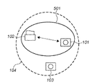
図1は、本実施形態におけるネットワークシステムの構成の一例を示す図である。図1に示す例は、パワーセーブモードを開始する前のカメラ101、プリンタ102、カメラ103によって構成されるネットワーク104の構成である。また、ネットワーク104はアドホックネットワークであり、特定の基地局を介することなく端末同士が直接通信を行うものである。
FIG. 1 is a diagram illustrating an example of a configuration of a network system in the present embodiment. The example shown in FIG. 1 is a configuration of the
尚、本実施形態では、パワーセーブ(PS)モードでカメラ101又は103のデータをプリンタ102に送信することを目的とする。
In this embodiment, the object is to transmit data of the
ここで、図2及び図3を用いて、図1に示すネットワークを構成するカメラ101及びプリンタ102の構成について説明する。図2は、本実施形態におけるカメラの構成の一例を示すブロック図である。また、図3は、本実施形態におけるプリンタの構成の一例を示すブロック図である。
Here, the configuration of the
カメラ101(103)は、図2に示すように、大きく分けて、カメラ機能部202と、無線モジュール201とに分かれている。カメラ機能部202は、カメラの撮影機能、TCP/IPのデータ処理機能、無線モジュール201のコントロール、及びデータ通信機能を備えている。また、無線モジュール201のコントロールは、コンパクトフラッシュ(登録商標)メモリとのインタフェースなどのメモリインタフェース203を利用して行う。
As shown in FIG. 2, the camera 101 (103) is roughly divided into a
無線モジュール201は、IEEE802.11規格(以下、802.11規格)の無線LAN機能であるMAC:Medium Access Control/PHY:Physical Layer、カメラ機能部202とのコントロール、及びデータ通信機能を備えている。また、無線モジュール201は、MAC処理部206とRF処理部205とアンテナ204に分かれる。MAC処理部206は、802.11規格の無線LANにおけるMAC、PHYの機能、カメラ機能部202とのコントロール、データ通信機能、RF処理部205のコントロール機能を持つ。また、MAC制御部206におけるRF処理部205のコントロールは、パワー制御のインタフェース208と送信及び受信処理のインタフェース207とによって行われる。また、パケットの送信パワーはパワー制御のインタフェース208によって行われる。そして、RF処理部205は、802.11規格のPHY機能を持ち、アンテナ204を通してデータを送受信する。
The wireless module 201 has a MAC: Medium Access Control / PHY: Physical Layer, a control with the
次に、プリンタ102は、図3に示すように、大きく分けて、プリンタ機能部302と、無線モジュール301とに分かれている。プリンタ機能部302は、プリンタの印刷機能、TCP/IPのデータ処理機能、無線モジュール301のコントロール、及びデータ通信機能を持つ。また、無線モジュール301の構成は、カメラ101の無線モジュール201の構成と同じであり、その説明は省略する。
Next, as shown in FIG. 3, the
図1において、カメラ101がネットワーク104に参加する場合、図2に示すカメラ機能部202より無線モジュール201に対してネットワークに参加するコマンドを発行し、MAC処理部206とRF処理部205とによって802.11規格の無線信号を送信し、ネットワークを形成する。
In FIG. 1, when the
図1に示す状態は、カメラ101及び103が共にプリンタ102とアクティブモードで通信を行っている状態である。ここで、カメラ101がプリンタ102とパワーセーブモードを開始する処理、及びプリンタ102がカメラ101からのパワーセーブモードの開始要求を受信した場合の処理について説明する。まず、図4を用いて、カメラ101においてパワーセーブモードを開始する処理について説明する。
The state shown in FIG. 1 is a state in which the
図4は、カメラ側におけるパワーセーブモード開始処理を示すフローチャートである。まず、ステップS401において、カメラ101が上位レイヤからパワーセーブモードの開始要求を受信すると、ステップS402へ進み、パワーセーブモードの開始要求を通信相手であるプリンタ102へ送信する。これにより、プリンタ102ではカメラ101にパワーセーブモードの開始確認を送信する。
FIG. 4 is a flowchart showing power save mode start processing on the camera side. First, in step S401, when the
その後、ステップS403において、カメラ101がプリンタ102からパワーセーブモードの開始確認を受信すると、ステップS404へ進み、プリンタ102のMACアドレス以外を破棄するフィルタを設定する。具体的には、図2に示すカメラ101のカメラ機能部202が無線モジュール201へMACフィルタの設定コマンドを発行することで行う。そして、設定コマンドを受けたMAC処理部206では、通信相手であるプリンタ102のMACアドレスを送信元とするパケットのみがカメラ機能部202に送信され、それ以外のパケットを破棄するようにフィルタ処理が行われる。
Thereafter, in step S403, when the
尚、上述のフィルタ処理は、データフレームにおけるユニキャスト及びマルチキャストに対して行い、マネージメントフレーム及びコントロールフレームに関しては適用しないものとする。 The above filtering process is performed on unicast and multicast in the data frame, and is not applied to the management frame and the control frame.
次に、ステップS405において、アウェイク状態とドーズ状態との間を規則的に遷移するパワーセーブモードを開始する処理を行う。具体的には、カメラ101のカメラ機能部202から無線モジュール201へパワーセーブ機能を実行するPSコマンドを発行し、MAC処理部206が間欠的にRF処理部205の電流を落とす処理である。
Next, in step S405, a process for starting a power save mode in which transition between the awake state and the doze state is performed regularly is performed. Specifically, it is a process in which a PS command for executing a power saving function is issued from the
これにより、図5に示すように、図1に示すネットワーク104とは別のネットワーク501がカメラ101とプリンタ102とによって形成される。
Thereby, as shown in FIG. 5, a
次に、図6を用いてプリンタ102において、カメラ101からパワーセーブモードの開始要求を受信した場合の処理について説明する。
Next, processing when the
図6は、プリンタ側でカメラからパワーセーブモードの開始要求を受信した場合の処理を示すフローチャートである。まず、ステップS601において、プリンタ102が相手(カメラ101)からパワーセーブモードの開始要求を受信すると、ステップS602へ進み、パワーセーブモードの開始確認をカメラ101へ送信する。
FIG. 6 is a flowchart showing processing when the printer side receives a request to start a power save mode from the camera. First, in step S601, when the
次に、ステップS603において、パワーセーブモードの開始要求をした相手(カメラ101)のMACアドレス以外を破棄するフィルタを設定する。具体的には、図3に示すプリンタ102のプリンタ機能部302が無線モジュール301へMACフィルタの設定コマンドを発行することで行う。尚、無線モジュール301のMAC処理部306の処理は、カメラ101のMAC処理部206の処理と同様である。
Next, in step S603, a filter is set that discards other than the MAC address of the partner (camera 101) that requested the start of the power save mode. Specifically, the
次に、ステップS604において、パワーセーブモードを実行するか否かを判定する。尚、プリンタ102は電源コンセントから十分な電力を供給されているため、省電力制御機能を動作させる必要はない。そのため、ステップS604のNoへ進み、パワーセーブモードを実行せず、そのまま処理を終了する。そして、図5に示す状態になり、プリンタ102はアクティブモードのまま通信を行い、カメラ101はパワーセーブモードへ移行して通信を行う。尚、ステップS604において、パワーセーブモードを実行すると判定した場合は、ステップS605においてパワーセーブモードへ移行して通信を行う。
Next, in step S604, it is determined whether to execute the power save mode. Since the
尚、図5に示すネットワーク501では、双方のMACアドレス以外からのパケットを破棄するようにフィルタが設定されているので、カメラ101ではプリンタ102からのデータのみが受信され、プリンタ102ではカメラ101からのデータのみが受信されるため、それ以外の端末のデータフレームが受信されることはなくなる。
In the
ここで、図7に示すように、カメラ101が省電力制御機能を動作させながらプリンタ102と通信している間に、カメラ701が新たにネットワーク104に入ってきた場合について説明する。
Here, as shown in FIG. 7, a case where the
まず、カメラ701は、カメラ701と同一のIPアドレスを持った端末が存在しないか否かを確認するために、ARP Requestメッセージをネットワーク104になげる。このとき、カメラ701に割り当てられたIPアドレスはカメラ101と同一のものとする。カメラ701からのARP Requestはマルチキャストデータフレームとして送信され、そのフレームはカメラ101及びプリンタ102のRF処理部205及びRF処理部305がそれぞれ受信する。
First, the
ここで、カメラ701がカメラ101と同一のIPアドレスであっても、カメラ101及びプリンタ101のMAC処理部206及びMAC処理部306はネットワーク501へのMACフィルタにより、カメラ101とプリンタ102以外のフレームは破棄され、データの不整合などは起こらない。
次に、図8を用いてカメラ101がパワーセーブモードでプリンタ102と通信を行いながら、プリンタ102からの指示に従ってパワーセーブモードからアクティブモードへ遷移する処理について説明する。
Here, even if the
Next, a process for switching from the power save mode to the active mode according to an instruction from the
図8は、カメラ側におけるパワーセーブモード終了処理を示すフローチャートである。まず、ステップS801において、カメラ101が上位レイヤからパワーセーブモードの終了要求を受信すると、ステップS802へ進み、パワーセーブモードの終了要求を通信相手であるプリンタ102へ送信する。これにより、プリンタ102ではカメラ101にパワーセーブモードの終了確認を送信する。
FIG. 8 is a flowchart showing power save mode end processing on the camera side. First, in step S801, when the
その後、ステップS803において、カメラ101がプリンタ102からパワーセーブモードの終了確認を受信すると、ステップS804へ進み、パワーセーブモードで動作中か否かを判定する。ここで、パワーセーブモードで動作中であれば、ステップS805へ進み、パワーセーブモードを終了する処理を行う。具体的には、カメラ機能部202から無線モジュール201へパワーセーブモードを終了するコマンドを発行し、MAC処理部206がRF処理部205の電流を流し続けるように制御する。
In step S803, when the
次に、ステップS806において、MACフィルタを解除する処理を行う。具体的には、カメラ機能部202が無線モジュール201にMACフィルタ解除コマンドを発行し、MAC処理部206がプリンタ102のMACアドレス以外を破棄するMACフィルタを解除する。これにより、ネットワーク104から受信したフレームを処理可能となる。
Next, in step S806, a process for canceling the MAC filter is performed. Specifically, the
次に、ステップS807において、カメラ機能部202にてIPアドレスの振り直しを行う。具体的には、IPアドレスを変更し、ARP Requestメッセージにてネットワーク上に同一IPアドレスが存在しないか否かを確認する。ここで、同一IPアドレスの端末が存在しない場合は、そのIPアドレスを新しいIPアドレスとして利用する。また、同一IPアドレスの端末が存在する場合は、再度IPアドレスを変更する。そして、同一IPアドレスの端末が存在しなくなるまで、上述のIPアドレスの変更を繰り返す。
In step S807, the
次に、図9を用いてプリンタ102において、カメラ101からパワーセーブモードの終了要求を受信した場合の処理について説明する。
Next, processing when the
図9は、プリンタ側でカメラからパワーセーブモードの開始要求を受信した場合の処理を示すフローチャートである。まず、ステップS901において、プリンタ102が相手(カメラ101)からパワーセーブモードの終了要求を受信すると、ステップS902へ進み、パワーセーブモードの終了確認をカメラ101へ送信する。
FIG. 9 is a flowchart showing processing when the printer side receives a request to start a power save mode from the camera. First, in step S901, when the
その後、ステップS903において、パワーセーブモードで動作中か否かを判定する。ここで、パワーセーブモードで動作中であれば、ステップS904へ進み、パワーセーブモードを終了する処理を行う。具体的には、プリンタ機能部302から無線モジュール301へパワーセーブモードを終了するコマンドを発行し、MAC処理部306がRF処理部305の電流を流し続けるように制御する。
Thereafter, in step S903, it is determined whether or not the apparatus is operating in the power save mode. If the operation is in the power save mode, the process advances to step S904 to perform a process for ending the power save mode. Specifically, a command for ending the power save mode is issued from the
次に、ステップS905において、MACフィルタを解除する処理を行う。具体的には、プリンタ機能部302が無線モジュール301にMACフィルタ解除コマンドを発行し、MAC処理部306がプリンタ102のMACアドレス以外を破棄するMACフィルタを解除する。これにより、ネットワーク104から受信したフレームを処理可能となる。
Next, in step S905, processing for canceling the MAC filter is performed. Specifically, the
次に、ステップS906において、プリンタ機能部302にてIPアドレスの振り直しを行う。この処理は、カメラ機能部202の処理と同様であり、その説明は省略する。
In step S906, the
これにより、図10に示すように、カメラ101、プリンタ102及びカメラ701が同じネットワーク104に参加することになるが、既にカメラ101とプリンタ102はIPアドレスの振り直しを行っているので、パワーセーブモードで動作中にネットワーク104に参加してきたカメラ701とIPアドレスが衝突することなく、データの不整合のないデータ通信を行うことができる。
As a result, as shown in FIG. 10, the
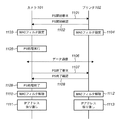
次に、図11を用いて、上述したカメラ101がプリンタ102との間でパワーセーブモードを開始し、パワーセーブモードでデータ通信を行い、その後、パワーセーブモードを終了するまでのシーケンスについて説明する。
Next, referring to FIG. 11, a sequence from when the above-described
尚、ここでは、既にプリンタ102がアドホックネットワークを開設しており、カメラ101がアドホックネットワークに参加し、パワーセーブモードでデータ通信を行う場合を例に説明する。また、アドホックネットワークにおけるパワーセーブについては公知のATIM(Announcement Traffic Indication Message)を使用するものであり、その説明は省略する。
Here, an example will be described in which the
図11は、本実施形態におけるパワーセーブモードの開始から終了までのシーケンスを示す図である。まずパワーセーブモードの開始要求1101がカメラ101からプリンタ102へ送信されると、これを受けてパワーセーブモードの開始確認1102がプリンタ102からカメラ101へ送信される。ここで、カメラ101及びプリンタ102の双方でMACフィルタの設定処理1103、1104がそれぞれ行われる。
FIG. 11 is a diagram showing a sequence from the start to the end of the power save mode in the present embodiment. First, when a power save
その後、カメラ101はパワーセーブモードに遷移する処理を実行1105し、データ通信1106がプリンタ102との間で開始される。このデータ通信1106は、カメラ101で撮影した画像データのファイルをプリンタ102へ転送するものである。
Thereafter, the
このデータ通信が終了すると、パワーセーブモードの終了要求1107がカメラ101からプリンタ102へ送信される。これを受けてパワーセーブモードの終了確認1108がプリンタ102からカメラ101へ送信される。これにより、カメラ101は、パワーセーブモードを終了する処理を実行1109し、アクティブモードへ遷移する。
When the data communication ends, a power save
そして、カメラ101及びプリンタ102の双方でMACフィルタの解除処理1110、1112と、IPアドレスの振り直し処理1111、1113がそれぞれ行われる。
Then, both the
以上説明した実施形態によれば、特定の基地局を介することなく端末同士が直接通信を行うアドホックネットワークにおいて、省電力制御機能を利用する際に、IPアドレスの衝突を防止し、不整合のないデータ通信を保証することができる。 According to the embodiment described above, when using a power saving control function in an ad hoc network in which terminals directly communicate with each other without going through a specific base station, collision of IP addresses is prevented and no inconsistency occurs. Data communication can be guaranteed.
また、MACフィルタは通信を行う上で既存のアドレスを利用するもので、暗号鍵変更のように双方で鍵変更の手順を決める必要がなく、実装も容易となる。 Further, the MAC filter uses an existing address for communication, and it is not necessary to determine the key change procedure on both sides as in the case of changing the encryption key, and the implementation is easy.
尚、本発明は複数の機器(例えば、ホストコンピュータ,インターフェース機器,リーダ,プリンタなど)から構成されるシステムに適用しても、1つの機器からなる装置(例えば、複写機,ファクシミリ装置など)に適用しても良い。 Even if the present invention is applied to a system composed of a plurality of devices (for example, a host computer, an interface device, a reader, a printer, etc.), it is applied to an apparatus (for example, a copier, a facsimile machine, etc.) composed of a single device. It may be applied.
また、本発明の目的は前述した実施形態の機能を実現するソフトウェアのプログラムコードを記録した記録媒体を、システム或いは装置に供給し、そのシステム或いは装置のコンピュータ(CPU若しくはMPU)が記録媒体に格納されたプログラムコードを読出し実行することによっても、達成されることは言うまでもない。 Another object of the present invention is to supply a recording medium in which a program code of software realizing the functions of the above-described embodiments is recorded to a system or apparatus, and the computer (CPU or MPU) of the system or apparatus stores the recording medium in the recording medium. Needless to say, this can also be achieved by reading and executing the programmed program code.
この場合、記録媒体から読出されたプログラムコード自体が前述した実施形態の機能を実現することになり、そのプログラムコードを記憶した記録媒体は本発明を構成することになる。 In this case, the program code itself read from the recording medium realizes the functions of the above-described embodiment, and the recording medium storing the program code constitutes the present invention.
このプログラムコードを供給するための記録媒体としては、例えばフロッピー(登録商標)ディスク,ハードディスク,光ディスク,光磁気ディスク,CD−ROM,CD−R,磁気テープ,不揮発性のメモリカード,ROMなどを用いることができる。 As a recording medium for supplying the program code, for example, a floppy (registered trademark) disk, a hard disk, an optical disk, a magneto-optical disk, a CD-ROM, a CD-R, a magnetic tape, a nonvolatile memory card, a ROM, or the like is used. be able to.
また、コンピュータが読出したプログラムコードを実行することにより、前述した実施形態の機能が実現されるだけでなく、そのプログラムコードの指示に基づき、コンピュータ上で稼働しているOS(オペレーティングシステム)などが実際の処理の一部又は全部を行い、その処理によって前述した実施形態の機能が実現される場合も含まれることは言うまでもない。 Further, by executing the program code read by the computer, not only the functions of the above-described embodiments are realized, but also an OS (operating system) operating on the computer based on the instruction of the program code. It goes without saying that a case where the function of the above-described embodiment is realized by performing part or all of the actual processing and the processing is included.
更に、記録媒体から読出されたプログラムコードが、コンピュータに挿入された機能拡張ボードやコンピュータに接続された機能拡張ユニットに備わるメモリに書込まれた後、そのプログラムコードの指示に基づき、その機能拡張ボードや機能拡張ユニットに備わるCPUなどが実際の処理の一部又は全部を行い、その処理によって前述した実施形態の機能が実現される場合も含まれることは言うまでもない。 Further, after the program code read from the recording medium is written in a memory provided in a function expansion board inserted into the computer or a function expansion unit connected to the computer, the function expansion is performed based on the instruction of the program code. It goes without saying that the CPU or the like provided in the board or the function expansion unit performs part or all of the actual processing and the functions of the above-described embodiments are realized by the processing.
Claims (9)
アドホックネットワークにおいて基地局を介さずに通信相手と直接無線通信する通信部と、
前記通信部を間欠的に起動状態にするパワーセーブ状態への切替に応答して、特定の通信相手からの信号を受信し、他の通信相手からの信号を破棄するように、前記特定の通信相手の物理アドレスに基づいて、受信する信号のフィルタ設定を行う設定手段と、
前記設定手段により前記特定の通信相手の物理アドレスに基づくフィルタ設定がなされているときに、前記フィルタ設定された前記特定の通信相手からの要求に従って前記パワーセーブ状態を終了する終了手段と、
前記終了手段による前記パワーセーブ状態の終了に応答して前記設定手段で設定したフィルタ設定を解除し、ネットワーク上の論理アドレスを再設定する再設定手段と、
を有することを特徴とする通信装置。 A communication device,
A communication unit that directly wirelessly communicates with a communication partner without using a base station in an ad hoc network ;
In response to switching to a power saving state that intermittently activates the communication unit, the specific communication is received so that a signal from a specific communication partner is received and a signal from another communication partner is discarded. Setting means for setting a filter of a received signal based on the physical address of the other party;
When the filter setting based on the physical address of the specific communication partner is made by the setting unit, an ending unit that ends the power saving state according to a request from the specific communication partner set as the filter;
In response to the end of the power save state by the ending means, resetting the filter setting set by the setting means, resetting the logical address on the network,
A communication apparatus comprising:
アドホックネットワークにおいて基地局を介さずに通信相手と直接無線通信する前記通信装置の通信部を間欠動作するパワーセーブ状態にする場合に、特定の通信相手からの信号を受信するように前記特定の通信相手の物理アドレスに基づくフィルタを設定する設定手段と、
前記通信部のパワーセーブ状態の終了に応答して、前記設定手段で設定したフィルタを解除する解除手段と、
前記通信部のパワーセーブ状態の終了及び前記解除手段による前記フィルタ解除に応答して、ネットワーク上の論理アドレスを再設定する再設定手段と、
を有することを特徴とする通信装置。 A communication device,
In the ad hoc network, when the communication unit of the communication device that performs direct wireless communication with the communication partner without going through the base station is put into a power saving state in which the communication device operates intermittently, the specific communication is received so as to receive a signal from the specific communication partner. A setting means for setting a filter based on the physical address of the other party;
Release means for releasing the filter set by the setting means in response to the end of the power saving state of the communication unit,
Resetting means for resetting a logical address on the network in response to the end of the power saving state of the communication unit and the cancellation of the filter by the releasing means;
A communication apparatus comprising:
アドホックネットワークにおいて基地局を介さずに通信相手と直接無線通信する前記通信装置の通信部を間欠的に起動状態にするパワーセーブ状態への切替に応答して、特定の通信相手からの信号を受信し、他の通信相手からの信号を破棄するように、前記特定の通信相手の物理アドレスに基づいて、受信する信号のフィルタ設定を行い、前記特定の通信相手の物理アドレスに基づくフィルタ設定がなされているときに、前記フィルタ設定された前記特定の通信相手からの要求に従って前記パワーセーブ状態を終了し、前記パワーセーブ状態の終了に応答して前記設定したフィルタ設定を解除し、ネットワーク上の論理アドレスを再設定することを特徴とする通信装置の制御方法。 A communication device control method comprising:
In response to switching to the power saving state that intermittently activates the communication unit of the communication device that directly wirelessly communicates with a communication partner without using a base station in an ad hoc network, receives a signal from a specific communication partner The received signal is set based on the physical address of the specific communication partner so that the signal from the other communication partner is discarded, and the filter setting based on the physical address of the specific communication partner is performed. And exiting the power saving state in accordance with a request from the specific communication partner set as the filter, and releasing the set filter setting in response to the end of the power saving state, A method for controlling a communication apparatus, comprising resetting an address .
アドホックネットワークにおいて基地局を介さずに通信相手と直接無線通信する前記通信装置の通信部を間欠動作するパワーセーブ状態にする場合に、特定の通信相手からの信号を受信するように前記特定の通信相手の物理アドレスに基づくフィルタを設定する設定工程と、
前記通信部のパワーセーブ状態の終了に応答して、前記設定工程において設定したフィルタを解除する解除工程と、
前記通信部のパワーセーブ状態の終了及び前記解除工程における前記フィルタ解除に応答して、ネットワーク上の論理アドレスを再設定するための処理を実行する再設定工程とを有することを特徴とする通信装置の制御方法。 A communication device control method comprising:
In the ad hoc network, when the communication unit of the communication device that performs direct wireless communication with the communication partner without going through the base station is put into a power saving state in which the communication device operates intermittently, the specific communication is received so as to receive a signal from the specific communication partner. A setting process for setting a filter based on the physical address of the other party;
In response to the end of the power saving state of the communication unit, a release step of releasing the filter set in the setting step,
And a resetting step for executing a process for resetting a logical address on the network in response to the end of the power saving state of the communication unit and the cancellation of the filter in the releasing step. Control method.
Priority Applications (3)
| Application Number | Priority Date | Filing Date | Title |
|---|---|---|---|
| JP2005073957A JP4549207B2 (en) | 2005-03-15 | 2005-03-15 | COMMUNICATION DEVICE AND ITS CONTROL METHOD |
| US11/354,815 US7721126B2 (en) | 2005-03-15 | 2006-02-16 | Communication apparatus and method with physical address filter for power-saving control state |
| CN2006100598078A CN1835496B (en) | 2005-03-15 | 2006-03-15 | Communication apparatus and method of controlling same |
Applications Claiming Priority (1)
| Application Number | Priority Date | Filing Date | Title |
|---|---|---|---|
| JP2005073957A JP4549207B2 (en) | 2005-03-15 | 2005-03-15 | COMMUNICATION DEVICE AND ITS CONTROL METHOD |
Publications (3)
| Publication Number | Publication Date |
|---|---|
| JP2006261854A JP2006261854A (en) | 2006-09-28 |
| JP2006261854A5 JP2006261854A5 (en) | 2008-04-24 |
| JP4549207B2 true JP4549207B2 (en) | 2010-09-22 |
Family
ID=37003099
Family Applications (1)
| Application Number | Title | Priority Date | Filing Date |
|---|---|---|---|
| JP2005073957A Expired - Fee Related JP4549207B2 (en) | 2005-03-15 | 2005-03-15 | COMMUNICATION DEVICE AND ITS CONTROL METHOD |
Country Status (3)
| Country | Link |
|---|---|
| US (1) | US7721126B2 (en) |
| JP (1) | JP4549207B2 (en) |
| CN (1) | CN1835496B (en) |
Families Citing this family (20)
| Publication number | Priority date | Publication date | Assignee | Title |
|---|---|---|---|---|
| US8527790B2 (en) * | 2004-09-21 | 2013-09-03 | Canon Kabushiki Kaisha | Communication apparatus and communication method |
| JP4310253B2 (en) * | 2004-09-21 | 2009-08-05 | キヤノン株式会社 | Communication apparatus and communication method |
| JP4336636B2 (en) * | 2004-09-21 | 2009-09-30 | キヤノン株式会社 | Communication apparatus and communication method |
| JP4700982B2 (en) * | 2005-03-02 | 2011-06-15 | キヤノン株式会社 | Communication apparatus and communication method |
| JP4732197B2 (en) * | 2006-03-07 | 2011-07-27 | キヤノン株式会社 | COMMUNICATION METHOD, COMMUNICATION DEVICE, COMMUNICATION SYSTEM, AND COMPUTER PROGRAM |
| US7971077B2 (en) * | 2006-12-21 | 2011-06-28 | Canon Kabushiki Kaisha | Information processing apparatus, information processing method, and program for executing the method |
| JP4929040B2 (en) * | 2007-05-10 | 2012-05-09 | キヤノン株式会社 | Communication apparatus and communication method |
| US7904739B2 (en) * | 2007-10-08 | 2011-03-08 | Hewlett-Packard Development Company, L.P. | Managing a power state for a peripheral |
| JP5270937B2 (en) | 2008-03-17 | 2013-08-21 | キヤノン株式会社 | COMMUNICATION DEVICE AND ITS CONTROL METHOD |
| JP5281312B2 (en) * | 2008-04-25 | 2013-09-04 | キヤノン株式会社 | COMMUNICATION DEVICE, ITS CONTROL METHOD, COMPUTER PROGRAM |
| JP5225033B2 (en) * | 2008-11-12 | 2013-07-03 | キヤノン株式会社 | COMMUNICATION DEVICE AND ITS CONTROL METHOD |
| CN102065577A (en) * | 2009-11-13 | 2011-05-18 | 英业达股份有限公司 | Hand-held communication device and packaging and managing method of hand-held communication device |
| JP2011121240A (en) * | 2009-12-09 | 2011-06-23 | Murata Machinery Ltd | Network printer |
| US8539260B2 (en) | 2010-04-05 | 2013-09-17 | Intel Corporation | Method, apparatus, and system for enabling platform power states |
| CN101895972A (en) * | 2010-04-20 | 2010-11-24 | 深圳市权智掌上电脑有限公司 | WiFi (Wireless Fidelity) power supply dynamic management system and method |
| JP5852431B2 (en) | 2011-12-09 | 2016-02-03 | キヤノン株式会社 | Image processing apparatus, control method thereof, and program |
| JP5705203B2 (en) * | 2012-12-28 | 2015-04-22 | キヤノン株式会社 | COMMUNICATION DEVICE, COMMUNICATION TERMINAL, ITS CONTROL METHOD, PROGRAM |
| JP6210753B2 (en) | 2013-06-24 | 2017-10-11 | キヤノン株式会社 | Information processing device |
| US10685121B2 (en) * | 2017-10-17 | 2020-06-16 | Quanta Computer Inc. | Secure environment examination |
| CN112788715B (en) * | 2019-11-08 | 2022-08-26 | 大唐移动通信设备有限公司 | Power-saving signal transmission method and device |
Citations (7)
| Publication number | Priority date | Publication date | Assignee | Title |
|---|---|---|---|---|
| JPH08275220A (en) * | 1995-03-27 | 1996-10-18 | Hewlett Packard Co <Hp> | Radio information processing method |
| JP2001057558A (en) * | 1999-06-10 | 2001-02-27 | Laboratories Of Image Information Science & Technology | Information processor |
| JP2002271376A (en) * | 2001-03-13 | 2002-09-20 | Sony Corp | Communication processing system, communication processing method, communication terminal, data transfer controller and program, thereof |
| JP2003018306A (en) * | 2001-06-28 | 2003-01-17 | Sharp Corp | Wireless data communication system, wireless main set and wireless slave set |
| JP2003526226A (en) * | 1998-01-07 | 2003-09-02 | マイクロソフト コーポレイション | Low-level content filtering |
| JP2004007187A (en) * | 2002-05-31 | 2004-01-08 | Toshiba Corp | Relaying apparatus and power supply control method |
| JP2004120213A (en) * | 2002-09-25 | 2004-04-15 | Murata Mach Ltd | Communication terminal device and its program |
Family Cites Families (11)
| Publication number | Priority date | Publication date | Assignee | Title |
|---|---|---|---|---|
| DE69232343D1 (en) * | 1991-08-13 | 2002-02-14 | Canon Kk | Image transfer device |
| KR20020010703A (en) | 1999-06-14 | 2002-02-04 | 러셀 비. 밀러 | Method and apparatus for disabling communications of a specified mode to a device capable of multi-mode communication |
| JP4145032B2 (en) * | 2001-08-07 | 2008-09-03 | 富士通株式会社 | Wireless LAN system |
| US7085868B2 (en) * | 2001-09-28 | 2006-08-01 | Intel Corporation | Method to minimize interrupt service and power consumption for wireless connectivity devices |
| US7133374B2 (en) * | 2002-03-19 | 2006-11-07 | Intel Corporation | Processing wireless packets to reduce host power consumption |
| JP3814563B2 (en) | 2002-05-24 | 2006-08-30 | キヤノン株式会社 | Wireless communication apparatus and control method thereof |
| US7685606B2 (en) * | 2002-06-27 | 2010-03-23 | Ting-Mao Chang | Power saving mobility aware system and method |
| US7257095B2 (en) * | 2003-07-30 | 2007-08-14 | Texas Instruments Incorporated | Power saving via physical layer address filtering in WLANs |
| JP4391277B2 (en) * | 2004-03-17 | 2009-12-24 | 株式会社リコー | Network control apparatus, image forming apparatus, image forming system, network control method, computer program, and recording medium |
| US7379992B2 (en) * | 2004-12-20 | 2008-05-27 | Mitac Technology Corp. | Network system and method for reducing power consumption |
| JP4700982B2 (en) * | 2005-03-02 | 2011-06-15 | キヤノン株式会社 | Communication apparatus and communication method |
-
2005
- 2005-03-15 JP JP2005073957A patent/JP4549207B2/en not_active Expired - Fee Related
-
2006
- 2006-02-16 US US11/354,815 patent/US7721126B2/en active Active
- 2006-03-15 CN CN2006100598078A patent/CN1835496B/en active Active
Patent Citations (7)
| Publication number | Priority date | Publication date | Assignee | Title |
|---|---|---|---|---|
| JPH08275220A (en) * | 1995-03-27 | 1996-10-18 | Hewlett Packard Co <Hp> | Radio information processing method |
| JP2003526226A (en) * | 1998-01-07 | 2003-09-02 | マイクロソフト コーポレイション | Low-level content filtering |
| JP2001057558A (en) * | 1999-06-10 | 2001-02-27 | Laboratories Of Image Information Science & Technology | Information processor |
| JP2002271376A (en) * | 2001-03-13 | 2002-09-20 | Sony Corp | Communication processing system, communication processing method, communication terminal, data transfer controller and program, thereof |
| JP2003018306A (en) * | 2001-06-28 | 2003-01-17 | Sharp Corp | Wireless data communication system, wireless main set and wireless slave set |
| JP2004007187A (en) * | 2002-05-31 | 2004-01-08 | Toshiba Corp | Relaying apparatus and power supply control method |
| JP2004120213A (en) * | 2002-09-25 | 2004-04-15 | Murata Mach Ltd | Communication terminal device and its program |
Also Published As
| Publication number | Publication date |
|---|---|
| US20060212732A1 (en) | 2006-09-21 |
| US7721126B2 (en) | 2010-05-18 |
| CN1835496A (en) | 2006-09-20 |
| CN1835496B (en) | 2011-10-05 |
| JP2006261854A (en) | 2006-09-28 |
Similar Documents
| Publication | Publication Date | Title |
|---|---|---|
| JP4549207B2 (en) | COMMUNICATION DEVICE AND ITS CONTROL METHOD | |
| US11050891B2 (en) | Data processing system executing predetermined data processing by plurality of apparatuses linking | |
| JP4336636B2 (en) | Communication apparatus and communication method | |
| JP4411225B2 (en) | Communication apparatus and communication method | |
| US8577999B2 (en) | Method for WLAN network and device role activation | |
| RU2350043C2 (en) | Device and communication method | |
| JP4955362B2 (en) | Wireless LAN system and wireless communication method | |
| JP5139851B2 (en) | Communication apparatus and network construction method thereof | |
| US7526251B2 (en) | Communication apparatus and control method thereof | |
| JP2007243434A (en) | Communication method, communication apparatus, communication system, and computer program | |
| JP2020502908A (en) | Improved power saving mode for wireless devices | |
| JP2007060029A (en) | Communication system, communication device, and their communication setting methods | |
| KR20090115479A (en) | Method and Apparatus for data transmission in a wireless local access network and System therefor | |
| JP2006135654A (en) | Communication system, communication device and communication method | |
| JP2009033490A (en) | Information communication terminal, radio communication apparatus, and radio communication network | |
| US7801574B2 (en) | Wireless communication apparatus, wireless network system, communication method and program | |
| WO2018051781A1 (en) | Communication device, communication method and program | |
| JP2005277937A (en) | Communication method and communication apparatus | |
| JP2002135314A (en) | Communication control method and communication equipment | |
| JP2007124540A (en) | Communication control apparatus, control method and control program for the communication control apparatus | |
| JP4723643B2 (en) | Communication method of wireless communication device | |
| JP2006093882A (en) | Radio communication device, control method thereof, and radio communication system | |
| KR102208987B1 (en) | Communication device, communication method, and program | |
| JP2006285090A (en) | Network construction method and communication equipment | |
| JP2005286626A (en) | Information processing system, scanning cycle setting method, and information processing apparatus |
Legal Events
| Date | Code | Title | Description |
|---|---|---|---|
| A521 | Request for written amendment filed |
Free format text: JAPANESE INTERMEDIATE CODE: A523 Effective date: 20080311 |
|
| A621 | Written request for application examination |
Free format text: JAPANESE INTERMEDIATE CODE: A621 Effective date: 20080311 |
|
| A977 | Report on retrieval |
Free format text: JAPANESE INTERMEDIATE CODE: A971007 Effective date: 20090427 |
|
| A131 | Notification of reasons for refusal |
Free format text: JAPANESE INTERMEDIATE CODE: A131 Effective date: 20090507 |
|
| A521 | Request for written amendment filed |
Free format text: JAPANESE INTERMEDIATE CODE: A523 Effective date: 20090706 |
|
| A131 | Notification of reasons for refusal |
Free format text: JAPANESE INTERMEDIATE CODE: A131 Effective date: 20100106 |
|
| A521 | Request for written amendment filed |
Free format text: JAPANESE INTERMEDIATE CODE: A523 Effective date: 20100302 |
|
| TRDD | Decision of grant or rejection written | ||
| A01 | Written decision to grant a patent or to grant a registration (utility model) |
Free format text: JAPANESE INTERMEDIATE CODE: A01 Effective date: 20100705 |
|
| A01 | Written decision to grant a patent or to grant a registration (utility model) |
Free format text: JAPANESE INTERMEDIATE CODE: A01 |
|
| A61 | First payment of annual fees (during grant procedure) |
Free format text: JAPANESE INTERMEDIATE CODE: A61 Effective date: 20100706 |
|
| R150 | Certificate of patent or registration of utility model |
Ref document number: 4549207 Country of ref document: JP Free format text: JAPANESE INTERMEDIATE CODE: R150 Free format text: JAPANESE INTERMEDIATE CODE: R150 |
|
| FPAY | Renewal fee payment (event date is renewal date of database) |
Free format text: PAYMENT UNTIL: 20130716 Year of fee payment: 3 |
|
| LAPS | Cancellation because of no payment of annual fees |