JP4213620B2 - DSRC OBE - Google Patents
DSRC OBE Download PDFInfo
- Publication number
- JP4213620B2 JP4213620B2 JP2004126720A JP2004126720A JP4213620B2 JP 4213620 B2 JP4213620 B2 JP 4213620B2 JP 2004126720 A JP2004126720 A JP 2004126720A JP 2004126720 A JP2004126720 A JP 2004126720A JP 4213620 B2 JP4213620 B2 JP 4213620B2
- Authority
- JP
- Japan
- Prior art keywords
- vehicle
- switch
- antenna
- dsrc
- determination
- Prior art date
- Legal status (The legal status is an assumption and is not a legal conclusion. Google has not performed a legal analysis and makes no representation as to the accuracy of the status listed.)
- Expired - Fee Related
Links
Images


Landscapes
- Devices For Checking Fares Or Tickets At Control Points (AREA)
- Mobile Radio Communication Systems (AREA)
- Radio Transmission System (AREA)
Description
この発明は、ETC(Electronic Toll Collection System:道路自動料金収受システム)、駐車場管理システム、民間課金システム(ガソリンスタンド、ドライブスルー)などに用いられ、路側機との間で狭域通信を行うDSRC(Dedicated Short−Range Communication:狭域通信)車載器に関するものである。 The present invention is used for ETC (Electronic Toll Collection System), parking lot management system, private billing system (gas station, drive-through), etc., and DSRC that performs narrow area communication with roadside devices (Dedicated Short-Range Communication) This invention relates to a vehicle-mounted device.
近年、車両と走行路上に設置された路側機(路側アンテナ)との間で通信を行い、課金決済、駐車場管理をするための情報を送受信するDSRC車載器は、よく知られている。一般に、DSRC車載器の受信感度は、路車間で通信ができる通信エリア内にあるか否かにかかわらず一定に設定されている。このため、DSRC車載器は、先にサービスが開始されたETCに対応できるように受信感度の調整をしている。
しかし、車載アンテナ位置、DSRC車載器の温度(高温時は受信感度が低下する)、車両走行条件など路車間通信の環境条件が悪い場合、例えば夏季の晴天日にETC料金ゲートを通過した場合において、車載アンテナがAピラーよりに設置されていて、なおかつDSRC車載器がダッシュボード上に置かれていたときに、ETC料金ゲートのレーン端側を車両が通過すれば、路車間通信が困難になる。このため、路車間通信において、DSRC車載器の受信感度を調整して、適切な受信感度にする必要がある。
従来、このような要求に応えるDSRC車載器として、路側機との路車間通信中に受信感度を上げることにより、通信エラーを防止したDSRC車載器が提案されている。(特許文献1参照)
2. Description of the Related Art In recent years, a DSRC on-vehicle device that performs communication between a vehicle and a roadside device (roadside antenna) installed on a traveling road and transmits and receives information for billing and parking management is well known. In general, the reception sensitivity of the DSRC in-vehicle device is set to be constant regardless of whether or not it is in a communication area where communication between road vehicles can be performed. For this reason, the DSRC in-vehicle device adjusts the reception sensitivity so as to be compatible with the ETC for which the service has been started first.
However, when the environmental conditions of road-to-vehicle communication such as the vehicle-mounted antenna position, the temperature of the DSRC vehicle-mounted device (reception sensitivity decreases at high temperatures), vehicle driving conditions, etc. are bad, for example, when passing the ETC fee gate on a sunny day in summer If the vehicle passes through the lane edge of the ETC toll gate when the vehicle-mounted antenna is installed from the A-pillar and the DSRC vehicle-mounted device is placed on the dashboard, road-to-vehicle communication becomes difficult. . For this reason, in road-to-vehicle communication, it is necessary to adjust the reception sensitivity of the DSRC in-vehicle device to obtain an appropriate reception sensitivity.
Conventionally, as a DSRC in-vehicle device that meets such requirements, a DSRC in-vehicle device that prevents communication errors by increasing reception sensitivity during road-to-vehicle communication with a roadside device has been proposed. (See Patent Document 1)
また、地下駐車場などの閉空間で、従来のDSRC車載器を用いて路車間通信を実施した場合には、路側アンテナの高さ、送信出力に制限があり、ETCと同様な路側アンテナの設定を出すのは難しい。例えば路側アンテナの高さは、ETCが6mに対して地下駐車場で2.5m前後になる。この場合、ETCのような通信エリアを確保しようとすると、路側アンテナの送信電力を上げる必要がある。 しかし、地下駐車場などの閉空間では、路側アンテナの送信電力を上げるとマルチパスによる影響が大きくなり、路車間通信エリア内に電界強度の落ち込みポイントが増加する。また電波飛びによる影響も大きくなり、先行車両が路車間通信をする筈の電波を後方車両が受信してしまい、後方車両と路車間通信する場合がある。そのため、DSRC車載器の受信感度を一定にすると、路車間通信エリアが狭くなる。
また、路車間通信の環境条件が悪い場合は、DSRC車載器の路車間通信エリアがさらに狭くなり、路車間通信ができない場合がある。この場合は、路車間通信中に受信感度を調整することもできないものである。
In addition, when road-to-vehicle communication is performed using a conventional DSRC vehicle-mounted device in a closed space such as an underground parking lot, there are restrictions on the height and transmission output of the roadside antenna. It is difficult to give For example, the height of the roadside antenna is about 2.5 m in an underground parking lot with an ETC of 6 m. In this case, in order to secure a communication area such as ETC, it is necessary to increase the transmission power of the roadside antenna. However, in a closed space such as an underground parking lot, increasing the transmission power of the roadside antenna increases the effect of multipath, increasing the field strength drop point in the road-to-vehicle communication area. In addition, there is a case where the influence of the radio wave jump becomes large, and the rear vehicle receives the saddle radio wave that the preceding vehicle performs road-to-vehicle communication, and the road vehicle communicates with the rear vehicle. Therefore, when the reception sensitivity of the DSRC in-vehicle device is made constant, the road-vehicle communication area becomes narrow.
Moreover, when the environmental conditions of road-to-vehicle communication are bad, the road-to-vehicle communication area of the DSRC on-board device may be further narrowed, and road-to-vehicle communication may not be possible. In this case, the reception sensitivity cannot be adjusted during road-to-vehicle communication.
従来のDSRC車載器は、上記のようにDSRC車載器の受信感度を一定にしているため、路車間通信時にDSRC車載器の受信感度を適切なレベルにする必要がある。
しかし、特許文献1の路側機との路車間通信中に受信感度を上げるものでは、地下駐車場などETC以外のサービスで路車間通信をする場合は、車載アンテナ位置、車両走行条件などの条件により、電波そのものを受信できないときがあり、DSRC車載器の受信感度を調整することができない問題があった。
Since the conventional DSRC in-vehicle device has a constant reception sensitivity of the DSRC on-vehicle device as described above, it is necessary to set the reception sensitivity of the DSRC on-vehicle device to an appropriate level during road-to-vehicle communication.
However, in the case of increasing the reception sensitivity during road-to-vehicle communication with the roadside machine of Patent Document 1, when performing road-to-vehicle communication using services other than ETC such as an underground parking lot, depending on conditions such as the vehicle-mounted antenna position and vehicle driving conditions In some cases, the radio wave itself cannot be received, and the reception sensitivity of the on-board DSRC device cannot be adjusted.
この発明は、上述のような課題を解決するためになされたものであり、ETCと地下駐車場管理システムなどそれ以外のサービスが受けられ、DSRC車載器の受信感度を調整しなくても路車間通信エラーを防止できるDSRC車載器を得ることを目的とする。 The present invention has been made to solve the above-described problems. Other services such as an ETC and an underground parking lot management system can be received, and the road-vehicle distance can be reduced without adjusting the reception sensitivity of the on-board DSRC device. An object of the present invention is to obtain a DSRC in-vehicle device that can prevent a communication error.
この発明に係わるDSRC車載器においては、車両に搭載され、路側機との間で狭域通信を行うDSRC車載器において、それぞれ異なるアンテナ特性を有し、路側機との間で狭域通信を行う二つの車載アンテナ、この二つの車載アンテナを切り替える切り替えスイッチ、路側機との通信開始前は、二つの車載アンテナを周期的に切り替えると共に、路側機との通信時には、一つの車載アンテナに固定するように切り替えスイッチを制御するスイッチ制御部、路側機から送信される情報に含まれ、路側機のアプリケーションの種類を示すアプリケーションIDを判定するAID判定手段、及びこのAID判定手段によるアプリケーションIDの判定に基づき、二つの車載アンテナのどちらに固定するかの判定を行い、この判定結果をスイッチ制御部に送信するスイッチ判定手段を備え、
スイッチ制御部は、路側機との通信開始時には、一つの車載アンテナに一時固定するとともに、スイッチ判定手段の判定結果に応じて一時固定された車載アンテナの固定継続か、または二つの車載アンテナを周期的に切り替えるように切り替えスイッチを制御するものである。
In the DSRC in-vehicle device according to the present invention, the DSRC on-vehicle device mounted on a vehicle and performing narrow-area communication with a roadside device has different antenna characteristics and performs narrow-area communication with the roadside device. two vehicle antenna changeover switch for switching the two vehicle-mounted antenna, before starting communication with the roadside device, the two vehicle-mounted antenna with periodically switched, during communication with the roadside device, in one of the in-vehicle antenna A switch control unit that controls the changeover switch to be fixed, an AID determination unit that is included in the information transmitted from the roadside device and that indicates an application ID indicating the type of application of the roadside device, and an application ID of the AID determination unit Based on the determination, it is determined which of the two in-vehicle antennas is fixed, and this determination result is switched to A switch judging means for transmitting to the control unit,
At the start of communication with the roadside device, the switch control unit temporarily fixes the vehicle-mounted antenna to one vehicle-mounted antenna, and continues to fix the vehicle-mounted antenna temporarily fixed according to the determination result of the switch determination unit, or cycles two vehicle-mounted antennas. The changeover switch is controlled so as to be switched automatically .
この発明は、以上説明したように、車両に搭載され、路側機との間で狭域通信を行うDSRC車載器において、それぞれ異なるアンテナ特性を有し、路側機との間で狭域通信を行う二つの車載アンテナ、この二つの車載アンテナを切り替える切り替えスイッチ、路側機との通信開始前は、二つの車載アンテナを周期的に切り替えると共に、路側機との通信時には、一つの車載アンテナに固定するように切り替えスイッチを制御するスイッチ制御部、路側機から送信される情報に含まれ、路側機のアプリケーションの種類を示すアプリケーションIDを判定するAID判定手段、及びこのAID判定手段によるアプリケーションIDの判定に基づき、二つの車載アンテナのどちらに固定するかの判定を行い、この判定結果をスイッチ制御部に送信するスイッチ判定手段を備え、
スイッチ制御部は、路側機との通信開始時には、一つの車載アンテナに一時固定するとともに、スイッチ判定手段の判定結果に応じて一時固定された車載アンテナの固定継続か、または二つの車載アンテナを周期的に切り替えるように切り替えスイッチを制御するので、二つの車載アンテナを切り替え使用することで、安定した路車間通信が可能となり、路車間通信エラーを防止することができる。
As described above, the present invention is a DSRC in-vehicle device that is mounted on a vehicle and performs narrow-area communication with a roadside device, and has different antenna characteristics and performs narrow-area communication with a roadside device. two vehicle antenna changeover switch for switching the two vehicle-mounted antenna, before starting communication with the roadside device, the two vehicle-mounted antenna with periodically switched, during communication with the roadside device, in one of the in-vehicle antenna A switch control unit that controls the changeover switch to be fixed, an AID determination unit that is included in the information transmitted from the roadside device and that indicates an application ID indicating the type of application of the roadside device, and an application ID of the AID determination unit Based on the determination, it is determined which of the two in-vehicle antennas is fixed, and this determination result is sent to the switch control unit. A switch judging means,
At the start of communication with the roadside device, the switch control unit temporarily fixes the vehicle-mounted antenna to one vehicle-mounted antenna, and continues to fix the vehicle-mounted antenna temporarily fixed according to the determination result of the switch determination unit, or cycles two vehicle-mounted antennas. Since the changeover switch is controlled so as to be switched automatically, by switching and using the two on-vehicle antennas, stable road-to-vehicle communication is possible, and road-to-vehicle communication errors can be prevented.
実施の形態1.
図1は、この発明の実施の形態1によるDSRC車載器を示す構成図である。
図1において、DSRC車載器の車載アンテナ1は、ETC用アプリケーション(AID=14)に適したアンテナ特性をもつAID14用アンテナ11と、DSRC用アプリケーション(AID=18)に適したアンテナ特性をもち、AID14用アンテナ11とはアンテナゲイン、指向性が異なるAID18用アンテナ12とにより構成され、路側機が送信する電波を受信して切り替えスイッチ2に送信する。切り替えスイッチ2は、AID14用アンテナ11とAID18用アンテナ12の切り替えをし、車載アンテナ1の固定を行なう。また、路側機から電波を受信するまでは、車載アンテナ1を周期的に切り替える。通信開始時には、切り替えスイッチ2を固定し、車載アンテナ1より送信された電波をRF部3に送信する。RF部3は、車載アンテナ1が受信した電波をアナログデータに変換後、モデム部4に送信する。モデム部4は、RF部3が変換したアナログデータをデジタルデータに変換後、データ処理部5のDSRC車載器制御部51に送信する。
Embodiment 1 FIG.
FIG. 1 is a configuration diagram showing a DSRC on-vehicle device according to Embodiment 1 of the present invention.
In FIG. 1, the vehicle-mounted antenna 1 of the DSRC vehicle-mounted device has an antenna characteristic suitable for an ETC application (AID = 14) and an antenna characteristic suitable for a DSRC application (AID = 18). The AID 14 antenna 11 is composed of an AID 18
データ処理部5のDSRC車載器制御部51は、路側機から送信される信号に含まれる、路側機のアプリケーションの種類を示すAID(アプリケーションID)をAID判定手段52に送信する。AID判定手段52は、DSRC車載器制御部51から受け取ったAIDを判定して、その判定結果をスイッチ判定手段53に送信する。スイッチ判定手段53は、AID判定手段52の判定結果に基づき、どちらの車載アンテナ1を使用するかを判定して、判定結果をスイッチ制御部6に送信する。なお、データ処理部5は、このDSRC車載器制御部51と、AID判定手段52と、スイッチ判定手段53とにより構成されている。
スイッチ制御部6は、スイッチ判定手段53の判定結果に基づいて、切り替え信号を切り替えスイッチ2に送信する。また路側機から電波を受信した場合は、データ処理部5のDSRC車載器制御部51より電波受信信号を受け取ると同時に、切り替えスイッチ2を一度固定する。また、切り替えスイッチ2よりどちらのスイッチを使用しているかというスイッチ信号も受け取り、このスイッチ信号をスイッチ判定手段53に送信する。
The DSRC OBE
The switch control unit 6 transmits a switching signal to the
図2は、この発明の実施の形態1によるDSRC車載器のデータ処理部の処理を示すフローチャートである。
次に、実施の形態1の動作を図2を参照しながら説明する。
DSRC車載器搭載車両が、ETCや地下駐車場管理システムなどの路車間通信でサービスを提供している通信エリア内に進入すると、DSRC車載器は、路側機が送信する電波を受信し、DSRC車載器制御部51は、スイッチ周期切り替え処理(ステップ551)から電波受信処理(ステップ552)に移行する。このとき電波受信処理(ステップ552)は、プログラム処理を行ない、AID判定手段52にデジタルデータ内に含まれるAIDを送信することで、AID判定処理(ステップ553)を開始させると同時に、電波を受信したことを示す電波受信信号をスイッチ制御部6に送信することで、切り替えスイッチ2を一時固定する。
FIG. 2 is a flowchart showing processing of the data processing unit of the DSRC on-vehicle device according to Embodiment 1 of the present invention.
Next, the operation of the first embodiment will be described with reference to FIG.
When a vehicle equipped with a DSRC vehicle-mounted device enters a communication area that provides services via road-to-vehicle communication such as ETC or an underground parking lot management system, the DSRC vehicle-mounted device receives the radio waves transmitted by the roadside device, The
AID判定処理(ステップ553)は、実際にAIDを解析して、AIDが14の場合は、AID14用スイッチ判定処理(ステップ554)に、AIDが18の場合は、AID18用スイッチ判定処理(ステップ555)に移行する。AID14用スイッチ判定処理(ステップ554)は、電波受信時に切り替えスイッチ2がどちらのスイッチで固定されているかという情報をスイッチ信号としてスイッチ制御部6より送られているため、スイッチ制御部6の情報がAID14用スイッチの場合は、切り替えスイッチ2の固定を維持する。スイッチ制御部6の情報が、AID18用スイッチの場合は、再びスイッチ周期切り替え処理(ステップ551)に移行する。
同様にAID18用スイッチ判定処理(ステップ555)は、電波受信時に切り替えスイッチ2がどちらのスイッチで固定されているかという情報を、スイッチ制御部6より送られているため、スイッチ制御部6の情報が、AID18用スイッチの場合は、切り替えスイッチ2の固定を維持する。スイッチ制御部6の情報が、AID14用スイッチの場合は、再びスイッチ周期切り替え処理(ステップ551)に移行する。
In the AID determination process (step 553), the AID is actually analyzed. When the AID is 14, the AID14 switch determination process (step 554) is performed. When the AID is 18, the AID18 switch determination process (step 555) is performed. ). The switch determination process for AID14 (step 554) is sent from the switch control unit 6 as information indicating which switch the
Similarly, in the switch determination processing for AID 18 (step 555), information about which switch is fixed by the
実施の形態1によれば、異なるパラメータをもつ2本の車載アンテナを切り替え使用するようにしたので、電波環境において安定した路車間通信が可能となり、路車間通信エラーを防止するDSRC車載器が得られる効果がある。
また、AID判定手段により、路側機から送信される情報の中に含まれているAIDがETC用アプリケーションかDSRC用アプリケーションかを判定して、その判定結果を用いて、車載アンテナの切り替えを行うので、容易にDSRCサービスの種類を判定できるとともに、判定結果に基づき、適切な車載アンテナの切り替えを行うことができる。
According to the first embodiment, since two on-vehicle antennas having different parameters are switched and used, a stable road-to-vehicle communication is possible in a radio wave environment, and a DSRC on-vehicle device that prevents road-to-vehicle communication errors is obtained. There is an effect.
In addition, the AID determination means determines whether the AID included in the information transmitted from the roadside device is an ETC application or a DSRC application, and switches the vehicle-mounted antenna using the determination result. In addition, it is possible to easily determine the type of the DSRC service, and it is possible to perform appropriate on-vehicle antenna switching based on the determination result.
実施の形態2.
実施の形態1では、AID判定手段52の結果と車載アンテナ1の種類が一致しないと、何度でもスイッチを周期的に切り替えてしまい、安定した通信ができない場合がある。そこで、実施の形態2は、AID判定手段52の結果と車載アンテナ1の種類が異なっていても、スイッチを固定することができるようにするものである。
図3は、この発明の実施の形態2によるDSRC車載器を示す構成図である。
図3において、1〜6、11、12、51、52は図1におけるものと同一のものである。図3では、スイッチ判定手段53に、何回判定したかをカウントするカウンタ機能を付加している。
In the first embodiment, if the result of the AID determination means 52 and the type of the in-vehicle antenna 1 do not match, the switch may be switched periodically as many times as possible, and stable communication may not be possible. Therefore, the second embodiment enables the switch to be fixed even if the result of the AID determination means 52 and the type of the in-vehicle antenna 1 are different.
FIG. 3 is a block diagram showing a DSRC vehicle-mounted device according to
In FIG. 3, 1 to 6, 11, 12, 51, 52 are the same as those in FIG. In FIG. 3, a counter function for counting how many times the determination is made is added to the switch determination means 53.
図4は、この発明の実施の形態2によるDSRC車載器のデータ処理部の処理を示すフローチャートである。
次に、実施の形態2の動作を図4を参照しながら説明する。
DSRC車載器搭載車両が、ETCや地下駐車場管理システムなどの路車間通信でサービスを提供している通信エリア内に進入すると、DSRC車載器は、路側機が送信する電波を受信し、DSRC車載器制御部51は、スイッチ周期切り替え処理(ステップ551)から電波受信処理(ステップ552)に移行する。このとき、電波受信処理(ステップ552)は、プログラム処理を行ない、AID判定手段52にデジタルデータ内に含まれるAIDを送信することで、AID判定処理(ステップ553)を開始させると同時に、電波を受信したことを示す電波受信信号をスイッチ制御部6に送信することで、切り替えスイッチ2を一時固定する。
FIG. 4 is a flowchart showing processing of the data processing unit of the on-board DSRC device according to
Next, the operation of the second embodiment will be described with reference to FIG.
When a vehicle equipped with a DSRC vehicle-mounted device enters a communication area that provides services via road-to-vehicle communication such as ETC or an underground parking lot management system, the DSRC vehicle-mounted device receives the radio waves transmitted by the roadside device, The
AID判定処理(ステップ553)は、実際にAIDを解析して、AIDが14の場合は、AID14用スイッチ判定処理(ステップ554)に、AIDが18の場合は、AID18用スイッチ判定処理(ステップ555)に移行する。AID14用スイッチ判定処理(ステップ554)は、電波受信時に切り替えスイッチ2がどちらのスイッチで固定されているかの情報をスイッチ制御部6より送られているため、スイッチ制御部6の情報がAID14用スイッチの場合は、スイッチ判定回数リセット処理(ステップ558)に移行し、スイッチ制御部6の情報がAID18用スイッチの場合は、スイッチ判定回数処理(ステップ556)に移行する。
同様にAID18用スイッチ判定処理(ステップ555)は、電波受信時に切り替えスイッチ2がどちらのスイッチで固定されているかの情報をスイッチ制御部6より送られているため、スイッチ制御部6の情報がAID18用スイッチの場合は、スイッチ判定回数リセット処理(ステップ558)に移行し、スイッチ制御部6の情報がAID14用スイッチの場合は、スイッチ判定回数処理(ステップ557)に移行する。
In the AID determination process (step 553), the AID is actually analyzed. When the AID is 14, the AID14 switch determination process (step 554) is performed. When the AID is 18, the AID18 switch determination process (step 555) is performed. ). In the switch determination process for AID14 (step 554), information on which switch is fixed by the
Similarly, in the switch determination processing for AID18 (step 555), information on which switch is fixed to which
スイッチ判定回数処理(ステップ556)およびスイッチ判定回数処理(ステップ557)は、それぞれAID14用スイッチ判定処理(ステップ554)およびAID18用スイッチ判定処理(ステップ555)を何回通過したかをカウントし、ある設定値以上になった場合は、スイッチ判定回数リセット処理(ステップ558)に移行し、ある設定値以下の場合は、スイッチ判定回数インクリメント処理(ステップ559)に移行する。
スイッチ判定回数リセット処理(ステップ558)は、スイッチ判定回数処理(ステップ556)およびスイッチ判定回数処理(ステップ557)のスイッチ判定回数を0にして、スイッチの固定を維持する。また、スイッチ判定回数インクリメント処理(ステップ559)では、スイッチ判定した数値に1を足し、再びスイッチ周期切り替え処理(ステップ551)に移行する。
The switch determination number process (step 556) and the switch determination number process (step 557) count how many times the AID14 switch determination process (step 554) and the AID18 switch determination process (step 555) have passed, respectively. If it is equal to or greater than the set value, the process proceeds to a switch determination number reset process (step 558). If it is less than a certain set value, the process proceeds to a switch determination number increment process (step 559).
In the switch determination number reset process (step 558), the switch determination number of the switch determination number process (step 556) and the switch determination number process (step 557) is set to 0, and the switch is kept fixed. In the switch determination number increment process (step 559), 1 is added to the switch determined numerical value, and the process proceeds to the switch cycle switching process (step 551) again.
ここで、スイッチ判定回数処理(ステップ556)およびスイッチ判定回数処理(ステップ557)で用いられる設定値は、例えばETC路車間通信の場合(AID=14)に、誤通信(アンテナ特性が2種類あるため、本来の通信エリア外で後方車両が受ける場合など)などを防ぐためにも、大きく設定するか、または処理をしないように設定しても良い。
また、地下駐車場など、AID=18を使用するサービスでは、電波環境(通信エリアがETCより狭い)が悪い可能性がある。したがって、2種類の車載アンテナを使用することで、安定した路車間通信を得ることが可能である。
Here, the setting values used in the switch determination number process (step 556) and the switch determination number process (step 557) are erroneous communication (two types of antenna characteristics), for example, in the case of ETC road-to-vehicle communication (AID = 14). Therefore, it may be set large or not to be processed in order to prevent a situation in which the rear vehicle receives outside the original communication area.
In addition, in a service using AID = 18 such as an underground parking lot, the radio wave environment (the communication area is narrower than ETC) may be bad. Therefore, stable road-to-vehicle communication can be obtained by using two types of vehicle-mounted antennas.
実施の形態2によれば、AID判定手段により判定されたAIDと、AIDの判定回数に基づいて、適切な車載アンテナに切り替えるので、路車間通信エラーを防止するDSRC車載器が得られる効果がある。 According to the second embodiment, switching to an appropriate vehicle-mounted antenna is performed based on the AID determined by the AID determination unit and the number of times of AID determination, so that there is an effect that a DSRC vehicle-mounted device that prevents road-to-vehicle communication errors can be obtained. .
実施の形態3.
実施の形態3は、実施の形態1および実施の形態2において、車載アンテナの切り替えスイッチ2の固定解除時期を、タイマー制御部54が設定した時間を経過した場合、路車間との無受信通信が規定時間を経過した場合、DSRCサービスの終了情報を車載器が受信した場合とし、切り替えスイッチ2の固定解除後は、初期状態である車載アンテナ1を周期的に切り替えるものとしている。
In the third embodiment, in the first and second embodiments, when the time set by the
図5は、この発明の実施の形態3によるDSRC車載器を示す構成図である。
図5において、1〜6、11、12、51〜53は図3におけるものと同一のものである。図5では、データ処理部5に、Aタイマー71とBタイマー72とを有するタイマー制御部54を設けている。
データ処理部5のDSRC車載器制御部51は、最初の初期接続時のデータ受信時にタイマー制御部54にタイマー情報を送信すると同時に、データ受信毎にタイマーをセットする。
タイマー制御部54は、初期通信時に時間をセットするAタイマー71と、受信毎に時間をセットするBタイマー72とを有しており、DSRC車載器制御部51からタイマー情報を受け取ると、路車間通信で必要十分な時間だけ、Aタイマー71をセットする。また、路車間通信でデータ受信する毎に必要十分な時間を、Bタイマー72にセットする。Aタイマー71またはBタイマー72のどちらかが時間切れとなった場合は、速やかにスイッチ制御部6にタイマーの時間切れ情報を送信する。
スイッチ制御部6は、タイマー制御部54からタイマーの時間切れ情報が送信された場合は、速やかに切り替えスイッチ2を初期状態に戻す。
FIG. 5 is a block diagram showing a DSRC on-vehicle device according to
In FIG. 5, 1-6, 11, 12, 51-53 are the same as those in FIG. In FIG. 5, the data processing unit 5 is provided with a
The DSRC
The
When timer expiration information is transmitted from the
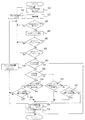
図6は、この発明の実施の形態3によるDSRC車載器のデータ処理部の処理を示すフローチャートである。
次に、実施の形態3の動作を図6を参照しながら説明する。
DSRC車載器搭載車両が、ETCや地下駐車場管理システムなどの路車間通信でサービスを提供している通信エリア内に進入すると、DSRC車載器は路側機が送信する電波を受信し、DSRC車載器制御部51は、スイッチ周期切り替え処理(ステップ551)から電波受信処理(ステップ552)に移行する。このとき電波受信処理(ステップ552)は、プログラム処理を行ない、AID判定手段52にデジタルデータ内に含まれるAIDを送信すると同時に、電波を受信したことを示す信号を、スイッチ制御部6に送信することで、切り替えスイッチ2を一時固定する。またプログラム処理を行ない、SRCサービス終了通知(ステップ565)が終了であれば、スイッチ固定フラグオフ処理(ステップ566)に移行し、DSRCサービス終了通知(ステップ565)が終了でなければ、A・Bタイマー設定処理(ステップ560)に移行する。
FIG. 6 is a flowchart showing processing of the data processing unit of the DSRC on-vehicle device according to
Next, the operation of the third embodiment will be described with reference to FIG.
When a vehicle equipped with a DSRC vehicle-mounted device enters a communication area that provides services through road-to-vehicle communication such as ETC or an underground parking lot management system, the DSRC vehicle-mounted device receives the radio wave transmitted by the roadside device. The
A・Bタイマー設定処理(ステップ560)では、Aタイマー71、Bタイマー72に時間をセットしてタイマー時間判定処理(ステップ561)に移行する。なお、Aタイマー71は、初期通信時に時間をセットする。Bタイマー72は、受信毎に時間をセットする。Aタイマー時間判定処理(ステップ561)では、A・Bタイマー設定処理(ステップ560)で、セットした時間がタイムアウトでない場合は、Bタイマー時間判定処理(ステップ562)に移行し、タイムアウトの場合は、スイッチ固定フラグオフ処理(ステップ566)に移行する。Bタイマー時間判定処理(ステップ562)では、A・Bタイマー設定処理(ステップ560)でセットした時間がタイムアウトでない場合は、スイッチ固定フラグ判定処理(ステップ563)に移行し、タイムアウトの場合は、スイッチ固定フラグオフ処理(ステップ566)に移行する。
In the A / B timer setting process (step 560), time is set in the
スイッチ固定フラグオフ処理(ステップ566)では、スイッチ固定フラグをOFFにして、初期状態であるスイッチ周期切り替え処理(ステップ551)に移行する。
スイッチ固定フラグ判定処理(ステップ563)では、フラグがONの場合は処理を終了する。フラグがOFFの場合は、AID判定処理(ステップ553)に移行する。AID判定処理(ステップ553)は、実際にAIDを解析して、AIDが14の場合は、AID14用スイッチ判定処理(ステップ554)に、AIDが18の場合は、AID18用スイッチ判定処理(ステップ555)に移行する。
In the switch fixing flag off process (step 566), the switch fixing flag is turned OFF, and the process proceeds to the switch cycle switching process (step 551) which is the initial state.
In the switch fixing flag determination process (step 563), the process ends if the flag is ON. If the flag is OFF, the process proceeds to AID determination processing (step 553). In the AID determination process (step 553), the AID is actually analyzed. When the AID is 14, the AID14 switch determination process (step 554) is performed. When the AID is 18, the AID18 switch determination process (step 555) is performed. ).
AID14用スイッチ判定処理(ステップ554)は、電波受信時に切り替えスイッチ2がどちらのスイッチで固定されているかの情報をスイッチ制御部6より送られているため、スイッチ制御部6の情報がAID14用スイッチの場合は、スイッチ判定回数リセット処理(ステップ558)に移行し、スイッチ制御部6の情報がAID18用スイッチの場合は、スイッチ判定回数処理(ステップ556)に移行する。同様にAID18用スイッチ判定処理(ステップ555)は、電波受信時に、切り替えスイッチ2がどちらのスイッチで固定されているかの情報をスイッチ制御部6より送られているため、スイッチ制御部6の情報がAID18用スイッチの場合は、スイッチ判定回数リセット処理(ステップ558)に移行し、スイッチ制御部6の情報がAID14用スイッチの場合は、スイッチ判定回数処理(ステップ557)に移行する。
スイッチ判定回数処理(ステップ556)およびスイッチ判定回数処理(ステップ557)は、それぞれAID14用スイッチ判定処理(ステップ554)およびAID18用スイッチ判定処理(ステップ555)を何回通過したかをカウントし、ある設定値以上になった場合は、スイッチ判定回数リセット処理(ステップ558)に移行し、ある設定値以下の場合は、スイッチ判定回数インクリメント処理(ステップ559)に移行する。
スイッチ判定回数リセット処理(ステップ558)は、スイッチ判定回数処理(ステップ556)およびスイッチ判定回数処理(ステップ557)のスイッチ判定回数を0にして、スイッチ固定フラグオン処理(ステップ564)に移行する。また、スイッチ判定回数インクリメント処理(ステップ559)では、スイッチ判定した数値に1を足し、再びスイッチ周期切り替え処理(ステップ551)に移行する。スイッチ固定フラグオン処理(ステップ564)では、スイッチ固定フラグをONにして、スイッチの固定を維持する。
In the switch determination process for AID14 (step 554), information on which switch is fixed by the
The switch determination number process (step 556) and the switch determination number process (step 557) count how many times the AID14 switch determination process (step 554) and the AID18 switch determination process (step 555) have passed, respectively. If it is equal to or greater than the set value, the process proceeds to a switch determination number reset process (step 558). If it is less than a certain set value, the process proceeds to a switch determination number increment process (step 559).
In the switch determination number reset process (step 558), the switch determination number of the switch determination number process (step 556) and the switch determination number process (step 557) is set to 0, and the process proceeds to the switch fixing flag ON process (step 564). In the switch determination number increment process (step 559), 1 is added to the switch determined numerical value, and the process proceeds to the switch cycle switching process (step 551) again. In the switch fixing flag ON process (step 564), the switch fixing flag is turned ON to maintain the switch fixing.
実施の形態3によれば、車載アンテナの切り替えスイッチの固定解除時期を、タイマー制御部が設定した時間を経過した場合、路車間との無受信通信が規定時間を経過した場合、DSRCサービスの終了情報を車載器が受信した場合とし、切り替えスイッチの固定解除後は、初期状態である2本の車載アンテナを周期的に切り替えるようにしたので、速やかに初期状態に移行し、次の路車間通信に備えることができるDSRC車載器が得られる効果がある。 According to the third embodiment, when the time set by the timer control unit has elapsed for the fixed release timing of the on-vehicle antenna changeover switch, when the non-reception communication between the road and vehicle has passed the specified time, the DSRC service is terminated. When information is received by the vehicle-mounted device, and after the change-over switch is unfixed, the two vehicle-mounted antennas that are in the initial state are periodically switched. There is an effect that a DSRC vehicle-mounted device that can be prepared for is obtained.
1 車載アンテナ
2 切り替えスイッチ
3 RF部
4 モデム部
5 データ処理部
6 スイッチ制御部
11 AID14用アンテナ
12 AID18用アンテナ
51 DSRC車載器
52 AID判定手段
53 スイッチ判定手段
54 タイマー制御部
71 Aタイマー
72 Bタイマー
DESCRIPTION OF SYMBOLS 1 In-
Claims (5)
上記スイッチ制御部は、上記路側機との通信開始時には、一つの車載アンテナに一時固定するとともに、上記スイッチ判定手段の判定結果に応じて上記一時固定された上記車載アンテナの固定継続か、または上記二つの車載アンテナを周期的に切り替えるように上記切り替えスイッチを制御することを特徴とするDSRC車載器。 In a DSRC vehicle-mounted device that is mounted on a vehicle and performs narrow-area communication with a roadside device, the two vehicle-mounted antennas that have different antenna characteristics and perform narrow-band communication with the roadside device, the two vehicle-mounted antennas changeover switch for switching the antenna, before starting communication with the roadside device, the two vehicle-mounted antenna with switched periodically, at the time of communication between the roadside device, the switching to secure the one of the in-vehicle antenna Based on a switch control unit that controls a switch, an AID determination unit that is included in the information transmitted from the roadside device and that indicates an application ID indicating the type of application of the roadside device, and an application ID determination by the AID determination unit , Which of the two on-vehicle antennas is fixed is determined, and the result of the determination is sent to the switch control unit A switch judging means for transmitting,
The switch control unit is temporarily fixed to one vehicle-mounted antenna at the start of communication with the roadside device, and the fixed vehicle-mounted antenna is continuously fixed according to the determination result of the switch determination unit, or the A DSRC vehicle-mounted device that controls the changeover switch so as to periodically switch between two vehicle-mounted antennas .
上記スイッチ判定手段は、上記スイッチ制御部によって固定された車載アンテナと、上記AID判定手段により新たに判定されたアプリケーションIDに適する車載アンテナとが不一致の場合に、上記不一致の回数をカウントするカウンタ手段を有し、上記カウンタ手段による不一致の回数が所定値を超えたとき、上記スイッチ制御部によって固定された車載アンテナの固定を維持する判定を行うことを特徴とするDSRC車載器。 In a DSRC vehicle-mounted device that is mounted on a vehicle and performs narrow-area communication with a roadside device, the two vehicle-mounted antennas that have different antenna characteristics and perform narrow-band communication with the roadside device, the two vehicle-mounted antennas A changeover switch for switching antennas. Before the start of communication with the roadside unit, the two onboard antennas are periodically switched. At the start of communication with the roadside unit, the changeover switch is fixed to one onboard antenna. Based on the switch control unit to be controlled, AID determination means for determining an application ID indicating the type of application of the roadside machine included in the information transmitted from the roadside machine, and the determination of the application ID by the AID determination means, Determine which of the two in-vehicle antennas is to be fixed, and use this switch control A switch judging means for transmitting the parts,
The switch determination unit is a counter unit that counts the number of mismatches when the vehicle-mounted antenna fixed by the switch control unit and the vehicle-mounted antenna that is newly determined by the AID determination unit do not match. has, when the number of mismatches by the counter means exceeds a predetermined value, D SRC OBE you and performs determination of maintaining a fixed vehicle antenna which is fixed by the switch controller.
Priority Applications (1)
| Application Number | Priority Date | Filing Date | Title |
|---|---|---|---|
| JP2004126720A JP4213620B2 (en) | 2004-04-22 | 2004-04-22 | DSRC OBE |
Applications Claiming Priority (1)
| Application Number | Priority Date | Filing Date | Title |
|---|---|---|---|
| JP2004126720A JP4213620B2 (en) | 2004-04-22 | 2004-04-22 | DSRC OBE |
Publications (2)
| Publication Number | Publication Date |
|---|---|
| JP2005309822A JP2005309822A (en) | 2005-11-04 |
| JP4213620B2 true JP4213620B2 (en) | 2009-01-21 |
Family
ID=35438527
Family Applications (1)
| Application Number | Title | Priority Date | Filing Date |
|---|---|---|---|
| JP2004126720A Expired - Fee Related JP4213620B2 (en) | 2004-04-22 | 2004-04-22 | DSRC OBE |
Country Status (1)
| Country | Link |
|---|---|
| JP (1) | JP4213620B2 (en) |
Families Citing this family (3)
| Publication number | Priority date | Publication date | Assignee | Title |
|---|---|---|---|---|
| JP4605068B2 (en) * | 2006-03-29 | 2011-01-05 | 株式会社デンソー | Vehicle communication device |
| JP5067379B2 (en) * | 2009-02-19 | 2012-11-07 | 株式会社デンソー | In-vehicle communication device and antenna selection method for in-vehicle communication device |
| DE112012005932B4 (en) * | 2012-02-24 | 2020-08-13 | Mitsubishi Electric Corporation | Communication device and navigation device arranged in the vehicle |
-
2004
- 2004-04-22 JP JP2004126720A patent/JP4213620B2/en not_active Expired - Fee Related
Also Published As
| Publication number | Publication date |
|---|---|
| JP2005309822A (en) | 2005-11-04 |
Similar Documents
| Publication | Publication Date | Title |
|---|---|---|
| EP3480678B1 (en) | On-vehicle communication device, communication control method and vehicle | |
| US20100299001A1 (en) | Vehicle communication terminal and vehicle communication system in which radio transmissions by the vehicle communication terminals are controlled by radio communication from base stations | |
| JP2000090395A (en) | Transmission equipment and method for inter-vehicle communication | |
| WO2012163051A1 (en) | On-board unit and power calibration method, device and system thereof | |
| CN107113576B (en) | Wireless communication device | |
| JP2009232065A (en) | Communication system, and on-board communication device | |
| WO2017051653A1 (en) | Wireless communication apparatus | |
| JP4213620B2 (en) | DSRC OBE | |
| JP2007304836A (en) | On-vehicle information presentation device and program | |
| KR102167704B1 (en) | Antenna system for highpass | |
| JP2004304542A (en) | Dsrc on-vehicle equipment | |
| JP2004282591A (en) | On-vehicle communication terminal for narrow-band communication | |
| JP3079929B2 (en) | Traffic information receiver | |
| JP2009105481A (en) | Vehicle communication system | |
| WO2015128999A1 (en) | On-board device and communication method using on-board device | |
| KR100527509B1 (en) | Communication method and system for a dsrc system | |
| JP2003185444A (en) | On-vehicle communication device | |
| JP2002141860A (en) | On-board narrow band radio communication equipment | |
| JP2003091795A (en) | On-vehicle device for communication between road and vehicle | |
| JP7468091B2 (en) | Vehicle-mounted device for toll payment, mobile communication terminal, toll payment system, and terminal control program | |
| JP5262391B2 (en) | Vehicle information providing device | |
| JP6204021B2 (en) | OBE | |
| JP4215196B2 (en) | Software defined radio and control method thereof | |
| JP4399330B2 (en) | Narrow wireless communication system | |
| JP3712543B2 (en) | DGPS FM multiplex broadcast receiver |
Legal Events
| Date | Code | Title | Description |
|---|---|---|---|
| A621 | Written request for application examination |
Free format text: JAPANESE INTERMEDIATE CODE: A621 Effective date: 20061207 |
|
| A977 | Report on retrieval |
Free format text: JAPANESE INTERMEDIATE CODE: A971007 Effective date: 20080724 |
|
| A131 | Notification of reasons for refusal |
Free format text: JAPANESE INTERMEDIATE CODE: A131 Effective date: 20080819 |
|
| A521 | Written amendment |
Free format text: JAPANESE INTERMEDIATE CODE: A523 Effective date: 20080924 |
|
| TRDD | Decision of grant or rejection written | ||
| A01 | Written decision to grant a patent or to grant a registration (utility model) |
Free format text: JAPANESE INTERMEDIATE CODE: A01 Effective date: 20081021 |
|
| A01 | Written decision to grant a patent or to grant a registration (utility model) |
Free format text: JAPANESE INTERMEDIATE CODE: A01 |
|
| A61 | First payment of annual fees (during grant procedure) |
Free format text: JAPANESE INTERMEDIATE CODE: A61 Effective date: 20081030 |
|
| FPAY | Renewal fee payment (event date is renewal date of database) |
Free format text: PAYMENT UNTIL: 20111107 Year of fee payment: 3 |
|
| R151 | Written notification of patent or utility model registration |
Ref document number: 4213620 Country of ref document: JP Free format text: JAPANESE INTERMEDIATE CODE: R151 |
|
| FPAY | Renewal fee payment (event date is renewal date of database) |
Free format text: PAYMENT UNTIL: 20111107 Year of fee payment: 3 |
|
| FPAY | Renewal fee payment (event date is renewal date of database) |
Free format text: PAYMENT UNTIL: 20121107 Year of fee payment: 4 |
|
| FPAY | Renewal fee payment (event date is renewal date of database) |
Free format text: PAYMENT UNTIL: 20121107 Year of fee payment: 4 |
|
| FPAY | Renewal fee payment (event date is renewal date of database) |
Free format text: PAYMENT UNTIL: 20131107 Year of fee payment: 5 |
|
| R250 | Receipt of annual fees |
Free format text: JAPANESE INTERMEDIATE CODE: R250 |
|
| R250 | Receipt of annual fees |
Free format text: JAPANESE INTERMEDIATE CODE: R250 |
|
| R250 | Receipt of annual fees |
Free format text: JAPANESE INTERMEDIATE CODE: R250 |
|
| R250 | Receipt of annual fees |
Free format text: JAPANESE INTERMEDIATE CODE: R250 |
|
| R250 | Receipt of annual fees |
Free format text: JAPANESE INTERMEDIATE CODE: R250 |
|
| LAPS | Cancellation because of no payment of annual fees |