JP4136858B2 - Position detection device and information input device - Google Patents
Position detection device and information input device Download PDFInfo
- Publication number
- JP4136858B2 JP4136858B2 JP2003322137A JP2003322137A JP4136858B2 JP 4136858 B2 JP4136858 B2 JP 4136858B2 JP 2003322137 A JP2003322137 A JP 2003322137A JP 2003322137 A JP2003322137 A JP 2003322137A JP 4136858 B2 JP4136858 B2 JP 4136858B2
- Authority
- JP
- Japan
- Prior art keywords
- information
- unit
- electromagnetic wave
- detection
- detection unit
- Prior art date
- Legal status (The legal status is an assumption and is not a legal conclusion. Google has not performed a legal analysis and makes no representation as to the accuracy of the status listed.)
- Expired - Fee Related
Links
Images


Classifications
-
- G—PHYSICS
- G06—COMPUTING; CALCULATING OR COUNTING
- G06F—ELECTRIC DIGITAL DATA PROCESSING
- G06F3/00—Input arrangements for transferring data to be processed into a form capable of being handled by the computer; Output arrangements for transferring data from processing unit to output unit, e.g. interface arrangements
- G06F3/01—Input arrangements or combined input and output arrangements for interaction between user and computer
- G06F3/03—Arrangements for converting the position or the displacement of a member into a coded form
- G06F3/041—Digitisers, e.g. for touch screens or touch pads, characterised by the transducing means
- G06F3/042—Digitisers, e.g. for touch screens or touch pads, characterised by the transducing means by opto-electronic means
Landscapes
- Engineering & Computer Science (AREA)
- General Engineering & Computer Science (AREA)
- Theoretical Computer Science (AREA)
- Human Computer Interaction (AREA)
- Physics & Mathematics (AREA)
- General Physics & Mathematics (AREA)
- Geophysics And Detection Of Objects (AREA)
- Position Fixing By Use Of Radio Waves (AREA)
- Length Measuring Devices By Optical Means (AREA)
Description
本発明は、インターフェース部分を透過する電磁波を利用して、電磁波を放射する物体の空間位置の情報を知る空間位置検出方法及び装置、物体とインターフェース部分の位置関係についての情報を検出したらそれを所定の解釈方法に従って処理して装置の動作、情報や信号の入力状態を制御する情報入力方法及び装置に関する。 The present invention relates to a spatial position detection method and apparatus for knowing information on the spatial position of an object that radiates electromagnetic waves using electromagnetic waves transmitted through the interface part, and detects information on the positional relationship between the object and the interface part when the information is detected. It is related with the information input method and apparatus which control according to the interpretation method, and control the operation | movement of an apparatus, and the input state of information or a signal.
空間位置検出装置として、例えば、複数の赤外線カメラを用いて、人体から放射する赤外線より画像を形成し、検出された画像より人体の中心座標を演算し、位置を検出する3次元位置検出装置がある(特許文献1参照)。また、LEDよりビームを放射し、物体より反射される電磁波より、反射光の角度と強度を演算し、物体の位置を検出するものがある(特許文献2参照)。 As a spatial position detection device, for example, there is a three-dimensional position detection device that uses a plurality of infrared cameras to form an image from infrared rays radiated from the human body, calculates the center coordinates of the human body from the detected image, and detects the position. Yes (see Patent Document 1). In addition, there is an apparatus that detects the position of an object by calculating the angle and intensity of reflected light from an electromagnetic wave radiated from an LED and reflected from the object (see Patent Document 2).
また、電磁波を利用した情報入力装置としては、タッチパネルやペン入力装置が一般的である。例えば、ペン先より放射する光の2箇所ある受光素子(CCDとレンズで構成)への入射角度情報を、CCD表面への光の照射位置情報より求めて、ペン先の位置を検出するペン入力装置がある(特許文献3参照)。
上記赤外線を用いる空間位置検出装置では、複数の赤外線カメラの像より物体の3次元画像を構成するため、個々の赤外線カメラの赤外線像には、或る程度の角度情報が含まれていないと、物体の3次元画像を構成することは難しい。各赤外線像に角度情報を含ませるためには、赤外線カメラを空間的に配置する必要があり、装置構成が大きくなるという課題がある。また、上記LEDを用いて、物体の反射光と強度より位置を検出する装置では、別途光源用の駆動装置が必要になり、こちらも装置構成が大きくなるという課題がある。 In the spatial position detection device using infrared rays, since a three-dimensional image of an object is formed from a plurality of infrared camera images, the infrared image of each infrared camera does not include a certain degree of angle information. It is difficult to construct a three-dimensional image of an object. In order to include angle information in each infrared image, it is necessary to spatially arrange the infrared camera, and there is a problem that the apparatus configuration becomes large. In addition, a device that detects the position from the reflected light and intensity of an object using the LED requires a separate light source driving device, which also has a problem that the device configuration becomes large.
また、上記ペン入力装置では、ペン先より光を放射し、受光素子への光の入射角度情報より位置を検出しているが、少なくとも、インターフェース部分前面に受光素子を配置するスペースを確保しなくてはならない。さらに、この場合、光は直進性を有するため、例えば、凹凸や曲面を有したインターフェース部分への位置検出用の受光素子配置が難しいといった、レイアウトの自由度に課題がある。 In the above pen input device, light is emitted from the pen tip and the position is detected from the incident angle information of the light to the light receiving element, but at least the space for arranging the light receiving element on the front surface of the interface portion is not secured. must not. Further, in this case, since the light has a straight traveling property, there is a problem in the degree of freedom in layout, for example, it is difficult to arrange the light receiving element for position detection on the interface portion having the unevenness or the curved surface.
上記課題に鑑み、本発明の空間位置検出方法は、任意形状を有していて一方の側から他方の側への情報や信号の伝達に係わるインターフェース部分に対する物体の相対的な空間位置の情報を検出する空間位置検出方法であって、該インターフェース部分を透過する該物体からの電磁波を検出して、その検出結果に基づいて物体の空間位置座標に関する情報(これは、その時々の位置座標データであってもよいし、位置座標データの時間的変化の態様などであってもよい)を演算することを特徴とする。 In view of the above problems, the spatial position detection method of the present invention has information on the relative spatial position of an object with respect to an interface part that has an arbitrary shape and is related to information transmission from one side to the other side and signal transmission. A spatial position detection method for detecting an electromagnetic wave from the object that passes through the interface portion, and information on the spatial position coordinate of the object based on the detection result (this is the position coordinate data at that time) Or may be a mode of temporal change of the position coordinate data).
上記本発明の空間位置検出方法において、以下のようなより具体的な態様が可能である。 In the spatial position detection method of the present invention, the following more specific modes are possible.
典型的には、前記インターフェース部分を透過する物体からの電磁波を集光することによって生じる集光スポットの位置を求めて電磁波を検出する。この集光手段としては、透過型のレンズ、曲面を有する反射型のミラーなどがある。集光手段がインターフェース部分の内面などに直接形成されている態様も可能である。また、物体からの電磁波を検出する変位検出手段としては、複数の電磁波検出素子で構成されたもの、複数の電磁波検出素子とアンテナアレイで構成されたものなどがある。集光手段は、変位検出手段のなるべく近くに配置される方が、集光手段のサイズが小さく出来て都合が良い。また、好ましくは、上記物体の先端は、電磁波を放射する熱源を有する。 Typically, the electromagnetic wave is detected by obtaining the position of a focused spot generated by collecting the electromagnetic wave from the object that passes through the interface portion. Examples of the condensing means include a transmissive lens, a reflective mirror having a curved surface, and the like. A mode in which the light collecting means is directly formed on the inner surface of the interface portion is also possible. Further, as a displacement detection means for detecting electromagnetic waves from an object, there are one constituted by a plurality of electromagnetic wave detection elements, one constituted by a plurality of electromagnetic wave detection elements and an antenna array, and the like. It is more convenient for the light collecting means to be arranged as close as possible to the displacement detecting means because the light collecting means can be reduced in size. Preferably, the tip of the object has a heat source that radiates electromagnetic waves.
また、予め前記インターフェース部分の形状情報を空間座標データとして記憶しておき、前記物体の空間位置座標と、該記憶されているインターフェース部分の空間座標データより、物体のインターフェース部分に対する相対的な空間位置情報に関する情報を演算するようにもできる。 Further, the shape information of the interface part is stored in advance as spatial coordinate data, and the relative spatial position of the object relative to the interface part is determined from the spatial position coordinates of the object and the stored spatial coordinate data of the interface part. It is also possible to calculate information related to information.
また、上記物体からの電磁波を集光する場合、集光スポットの強度分布のうち、最も信号強度が強い位置を集光スポットの位置として求め、該集光スポットの位置と電磁波を集光する際の光学特性より、物体から前記インターフェース部分に入射する電磁波の入射角度を求め、集光スポットの強度と物体からの電磁波の入射角度より、物体の空間位置座標に関する情報を演算することができる。この場合、使用開始時に、前記物体の既知の位置における集光スポットの強度を測定することによって、集光スポットの強度と電磁波の伝搬距離の関係に補正をかけてもよい。或いは、前記物体からの電磁波を複数集光して生じる複数の所定面上の集光スポットの位置を求め、複数の集光スポットの強度分布のうち、最も信号強度が強い位置を集光スポットの位置としてそれぞれ求め、該複数の集光スポットの位置と電磁波を集光する際の光学特性より、物体からの電磁波が前記インターフェース部分に入射する際の複数の電磁波の入射角度を求め、複数の電磁波の入射角度より、物体の空間位置座標に関する情報を演算することもできる。 When collecting the electromagnetic wave from the object, the position where the signal intensity is the strongest in the intensity distribution of the focused spot is obtained as the focused spot position, and the focused spot position and the electromagnetic wave are collected. From the optical characteristics, the incident angle of the electromagnetic wave incident on the interface portion from the object can be obtained, and information on the spatial position coordinates of the object can be calculated from the intensity of the focused spot and the incident angle of the electromagnetic wave from the object. In this case, the relationship between the intensity of the focused spot and the propagation distance of the electromagnetic wave may be corrected by measuring the intensity of the focused spot at a known position of the object at the start of use. Alternatively, the positions of the condensing spots on a plurality of predetermined surfaces generated by condensing a plurality of electromagnetic waves from the object are obtained, and the position having the strongest signal intensity among the intensity distributions of the plurality of condensing spots is determined. The position of each of the plurality of condensing spots and the optical characteristics at the time of condensing the electromagnetic waves are obtained as the positions, and the incident angles of the plurality of electromagnetic waves when the electromagnetic waves from the object are incident on the interface portion are obtained. It is also possible to calculate information related to the spatial position coordinates of the object from the incident angle.
また、予め前記インターフェース部分の物性の分布情報を記憶しておき、インターフェース部分上の電磁波の入射角度位置における、インターフェース部分が与える電磁波の伝搬特性への影響を考慮し、物体の空間位置に関する情報の演算に補正をかけてもよい。この場合、物性情報記憶部は、前記インターフェース部分の周辺環境に応じて、インターフェース部分の物性の分布情報を更新するようにもできる。 In addition, the physical property distribution information of the interface part is stored in advance, the influence on the propagation characteristics of the electromagnetic wave given by the interface part at the incident angle position of the electromagnetic wave on the interface part is considered, and the information on the spatial position of the object is stored. You may correct | amend a calculation. In this case, the physical property information storage unit can update the physical property distribution information of the interface part according to the surrounding environment of the interface part.
また、指向性及び透過性の観点から、好ましくは、前記物体より放射する電磁波の周波数帯域は、30GHzから30THzのうち、任意の帯域幅を有する電磁波を用いる。 Further, from the viewpoint of directivity and transparency, it is preferable to use an electromagnetic wave having an arbitrary bandwidth of 30 GHz to 30 THz as the frequency band of the electromagnetic wave radiated from the object.
更に、上記課題に鑑み、本発明の情報入力方法は、上記の空間位置検出方法を用いた情報入力方法であって、前記インターフェース部分の任意の地点と前記物体との相対的な距離に関する情報をモニタし、該モニタ結果を所定の解釈方法に従って処理して、装置の動作、情報や信号の入力状態を制御することを特徴とする。 Furthermore, in view of the above problems, an information input method according to the present invention is an information input method using the spatial position detection method described above, and includes information on a relative distance between an arbitrary point of the interface portion and the object. And monitoring and processing the monitoring result according to a predetermined interpretation method to control the operation of the apparatus and the input state of information and signals.
更に、上記課題に鑑み、本発明の空間位置検出装置は、上記の空間位置検出方法を行なうための空間位置検出装置であって、前記インターフェース部分を透過する物体からの電磁波を検出する少なくとも1つの電磁波検出部と、その検出結果に基づいて物体の空間位置座標に関する情報を演算する位置演算部を少なくとも有し、インターフェース部分は、物体からの電磁波を透過する特性を持ち、少なくとも電磁波検出部と位置演算部を、インターフェース部分を境に物体とは反対側の空間内に備える(或いは内包する)ことを特徴とする。また、本発明の位置検出装置は、物体の位置を検出するための位置検出装置であって、30GHzから30THzの周波数帯域内の電磁波を検出するための検出部と、前記検出部を格納している筐体と、前記筐体の外形情報を記憶している記憶部と、前記筐体に対して前記検出部と反対側に位置する物体から発生し、且つ前記筐体を透過してくる前記電磁波を、前記検出部が検出することにより取得される情報から、該物体と該検出部との相対的な位置情報を演算するための演算部と、を有し、前記演算部は、演算して取得される前記物体と前記検出部との相対的な位置情報と、前記記憶部が記憶している外形情報とを用いて、前記筐体と前記物体との相対的な位置情報を演算することを特徴とする。また、本発明の位置検出装置は、物体の位置を検出するための位置検出装置であって、30GHzから30THzの周波数帯域内の電磁波を検出するための検出部と、前記検出部を格納している筐体と、前記筐体の外形情報を記憶している記憶部と、前記筐体に対して前記検出部と反対側に位置する物体から発生し、且つ前記筐体を透過してくる前記電磁波を、前記検出部が検出することにより取得される情報から、該物体と該検出部との相対的な位置情報を演算するための演算部と、を有し、前記検出部が検出することにより取得される情報が、前記筐体に入射する該電磁波の入射角度及び強度であり、前記演算部は、前記入射角度と前記強度とから前記物体と前記検出部との相対的な位置情報を演算し、且つ、演算して取得される前記物体と前記検出部との相対的な位置情報と、前記記憶部が記憶している外形情報とを用いて、前記筐体と該物体との相対的な位置情報を演算することを特徴とする。 Furthermore, in view of the above problems, a spatial position detection device of the present invention is a spatial position detection device for performing the spatial position detection method described above, and includes at least one electromagnetic wave from an object that passes through the interface portion. It has at least an electromagnetic wave detection unit and a position calculation unit that calculates information related to the spatial position coordinates of the object based on the detection result, and the interface part has a characteristic of transmitting electromagnetic waves from the object, and at least the position of the electromagnetic wave detection unit and the position The arithmetic unit is provided (or included) in a space opposite to the object with the interface portion as a boundary. Also, position置検detection device of the present invention, there is provided a position detecting device for detecting the position of an object, and stores a detection unit for detecting an electromagnetic wave in the frequency band of 30THz from 30 GHz, the detector Generated from an object located on the opposite side of the detection unit to the case, and transmitted through the case the electromagnetic wave, have a, a computing section from Ru acquired information, for calculating the relative position information between said object and the detection portion by the detector unit detects the operation unit, the operation The relative position information between the casing and the object is calculated using the relative position information between the object and the detection unit acquired in this way and the external shape information stored in the storage unit. It is characterized by doing. The position detection device of the present invention is a position detection device for detecting the position of an object, and stores a detection unit for detecting electromagnetic waves in a frequency band of 30 GHz to 30 THz, and the detection unit. Generated from an object located on the opposite side of the detection unit with respect to the case, and transmitted through the case. An arithmetic unit for calculating relative position information between the object and the detection unit from information acquired by detecting the electromagnetic wave by the detection unit; and the detection unit detects the electromagnetic wave Is the incident angle and intensity of the electromagnetic wave incident on the casing, and the calculation unit obtains relative position information of the object and the detection unit from the incident angle and the intensity. The thing to be calculated and obtained by calculation Wherein the relative position information of the detection unit, by using the contour information the storage unit has stored, characterized by calculating the relative positional information between the housing and said object and.
更に、上記課題に鑑み、本発明の情報入力装置は、上記の空間位置検出装置を有する情報入力装置であって、前記インターフェース部分を境に物体とは反対側の空間内に備えられるか、または内包され、インターフェース部分の任意の地点と物体との相対的な距離に関する情報をモニタし、該モニタ結果を所定の解釈方法に従って処理して、装置の動作、情報や信号の入力状態を制御する情報入出力制御部を有することを特徴とする。また、本発明の情報入力装置は、上記の位置検出装置を含み構成される情報入力装置であって、情報端末装置と、前記演算部が演算した前記相対位置に基づいて、前記情報端末装置の動作を制御するための制御部と、を有することを特徴とする。 Furthermore, in view of the above problems, an information input device of the present invention is an information input device having the spatial position detection device described above, and is provided in a space opposite to an object with the interface portion as a boundary, or Information included to monitor information on the relative distance between an arbitrary point on the interface part and an object, and process the monitor result according to a predetermined interpretation method to control the operation of the apparatus, information and signal input state An input / output control unit is provided. Further, the information input device of the present invention is a composed information input device includes the above-mentioned position置検detection device, and an information terminal apparatus, on the basis of the relative position where the operation unit is computed, the information terminal device And a control unit for controlling the operation of the apparatus.
上記本発明の情報入力装置において、以下のようなより具体的な構成を採り得る。すなわち、情報入出力制御部は、前記インターフェース部分を幾つかの領域に分割し、各領域の位置情報と、各領域について前記情報入力装置が行う動作を関連づけ、各領域を或る所定の機能を有する仮想的な制御素子として管理しうる。また、情報入力装置を構成するデバイスに対応する領域については、該デバイスの動作をそれぞれ制御しうる。そして、前記物体は電磁波を放射する人体の一部であり、情報入出力制御部は、ボタンやスイッチに対応する仮想的な制御素子に該物体が接近した時、該仮想的な制御素子と該物体との距離をモニタし、ある一定の距離を下回るか、接触した場合に、予め関連づけられた動作を行い、また、該デバイスに物体が接近した時、或る一定の距離を下回るか、接触した場合に、該デバイスを動作させ得る。また、全ての該仮想的な制御素子や該デバイスに、物体が一定期間近づくことがない場合、情報入力装置の動作を或る所定のモードにすることもできる。 In the information input device of the present invention, the following more specific configuration can be adopted. That is, the information input / output control unit divides the interface part into several areas, associates position information of each area with the operation performed by the information input device for each area, and sets each area to have a predetermined function. It can be managed as a virtual control element. In addition, for the area corresponding to the device constituting the information input apparatus, the operation of the device can be controlled. The object is a part of a human body that radiates electromagnetic waves, and the information input / output control unit, when the object approaches a virtual control element corresponding to a button or a switch, Monitors the distance to an object and performs a pre-associated action when it falls below or touches a certain distance, and when the object approaches the device, it falls below a certain distance or touches If so, the device can be operated. Further, when an object does not approach all the virtual control elements and devices for a certain period, the operation of the information input device can be set to a certain predetermined mode.
また、情報入出力制御部は、前記インターフェース部分をGUI(Graphical
User Interface)が使用可能なディスプレイ領域と使用不可能な領域に分割し、GUIを構成する要素の位置と、その要素によって前記情報入力装置が行う動作を管理するようにできる。そして、前記物体は前記電磁波を放射するペン型の入力装置であり、該情報入出力制御部は、該GUIを構成する要素と物体との距離をモニタし、或る一定の距離を下回るか、接触した場合に、予め関連づけられた動作を行うようにできる。また、該ディスプレイ領域に、物体を用いて直接情報を書き込む場合、該物体の先端とディスプレイ領域の距離によって、線幅を変化させたり、色調を変化させるといった制御を行うようにもできる。
In addition, the information input / output control unit displays the interface portion with a GUI (Graphical
(User Interface) can be divided into display areas that can be used and areas that cannot be used, and the positions of elements constituting the GUI and the operations performed by the information input device can be managed by the elements. The object is a pen-type input device that radiates the electromagnetic wave, and the information input / output control unit monitors the distance between the elements constituting the GUI and the object, and is less than a certain distance, In the case of contact, an operation associated in advance can be performed. In addition, when information is directly written in the display area using an object, it is possible to perform control such as changing the line width or changing the color tone depending on the distance between the tip of the object and the display area.
また、情報入出力制御部は、前記インターフェース部分上のGUIを構成する要素の位置と、その要素によって前記情報入力装置が行う動作を管理するようにできる。そして、前記物体は前記電磁波を放射する人体の一部であり、該情報入出力制御部は、該GUIを構成する要素と物体との距離をモニタし、或る一定の距離を下回るか、接触した場合に、予め関連づけられた動作を行うようにできる。また、該物体を用いて所定のシンボルをインターフェース部分上になぞることにより、該情報入力装置の動作を制御するようにもできる。 In addition, the information input / output control unit can manage the position of the elements constituting the GUI on the interface portion and the operation performed by the information input device based on the elements. The object is a part of a human body that radiates the electromagnetic wave, and the information input / output control unit monitors a distance between an element constituting the GUI and the object, and is less than a certain distance or is in contact with the object. In such a case, an operation associated in advance can be performed. Further, the operation of the information input device can be controlled by tracing a predetermined symbol on the interface portion using the object.
本発明によれば、インターフェース部分を透過する電磁波を検出することにより、例えば、温度を有する物体から自然放射されている電磁波を利用し、この電磁波を発生する物体の、インターフェース部分に対する相対的な位置を検出し、インターフェース部分と電磁波を発生する物体との相対的な距離ないし位置関係に関する情報によって、装置の動作などを制御する様にできるので、以下のような効果が期待できる。 According to the present invention, the electromagnetic wave transmitted through the interface part is detected, for example, the electromagnetic wave naturally radiated from an object having temperature is used, and the relative position of the object generating the electromagnetic wave with respect to the interface part is determined. And the operation of the apparatus can be controlled based on information on the relative distance or positional relationship between the interface portion and the object that generates electromagnetic waves, and the following effects can be expected.
インターフェース部分近傍の物体の位置検出技術に関し、特別な信号源や走査機構を用いずに物体の空間位置検出を実現する方法及び装置を提供できる。また、その空間位置検出技術を用いて検出された空間位置に関する情報を所定の解釈方法に従って処理して装置の動作、情報や信号の入力状態を制御する情報入力方法及び装置を提供できる。 With respect to the position detection technique of the object near the interface portion, it is possible to provide a method and apparatus for realizing the spatial position detection of an object without using a special signal source or scanning mechanism. In addition, it is possible to provide an information input method and apparatus for processing the information on the spatial position detected using the spatial position detection technique according to a predetermined interpretation method to control the operation of the apparatus and the input state of information and signals.
インターフェース部分には、使用する電磁波を透過する特性のみを有していれば、物体の位置を特定するための特別な機械的な走査機構などは必要なくできるため、装置の小型化が容易に実現できる。また、このような機械的な走査機構が必要ないということは、例えばディスプレイ装置を考えた場合、情報の入出力を行うディスプレイ部のサイズを最大に保つことができるなど、装置レイアウトの自由度を上げられる。 If the interface part has only the property of transmitting the electromagnetic wave to be used, a special mechanical scanning mechanism for specifying the position of the object can be dispensed with, so the device can be easily downsized. it can. Further, the fact that such a mechanical scanning mechanism is not necessary means that, for example, when a display device is considered, the size of the display unit for inputting and outputting information can be kept at a maximum, and the degree of freedom in device layout is increased. Raised.
物体とインターフェース部分との相対的な位置関係を求めているため、インターフェース部分の形状は必ずしも平面である必要はなく、様々な形状を有するインターフェース部分に対する位置検出への応用が容易である。 Since the relative positional relationship between the object and the interface portion is obtained, the shape of the interface portion does not necessarily have to be a plane, and the application to position detection with respect to the interface portion having various shapes is easy.
物体とインターフェース部分の相対的な位置関係に関する情報より、情報の操作などを行うようにもできるため、ボタン、スイッチ等の機械的な部品を大幅に減らすことが可能になり、装置の小型化が容易に実現できる。 Since it is also possible to operate information from the information on the relative positional relationship between the object and the interface part, it is possible to greatly reduce the mechanical parts such as buttons and switches, thereby reducing the size of the device. It can be easily realized.
人が自然に行う動作、或いは情報入力装置の取り巻く環境状況などによって、装置動作などを制御するようにもできるので、操作性も上がり、誤作動を防止することもできる。 Since the operation of the apparatus can be controlled according to the action naturally performed by the person or the environment surrounding the information input apparatus, the operability can be improved and the malfunction can be prevented.
装置のインターフェース部分自体の物性の分布特性や、周辺環境を考慮して、検出する物体の位置情報に対して補正をかける場合、より正確な位置検出が可能になる。 More accurate position detection is possible when correction is made to the position information of the object to be detected in consideration of the distribution characteristics of physical properties of the interface portion of the apparatus itself and the surrounding environment.
本発明の実施の形態について、図面を参照して説明する。図中、同一部分に関しては、同符号を用いる。 Embodiments of the present invention will be described with reference to the drawings. In the figure, the same reference numerals are used for the same parts.
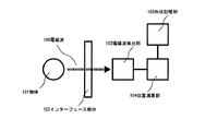
図1に本発明の物体の空間位置検出装置の一実施形態に関するブロック図を示す。図1のように、本実施形態の空間位置検出装置は、電磁波106を放射する物体101(人の手など)、電磁波106を透過するインターフェース部分102、インターフェース部分102を透過した電磁波106を検出する電磁波検出部103、電磁波検出部103の出力より物体101のインターフェース部分102に対する相対的な位置座標に関するデータ(これは、その時々の位置座標データであってもよいし、位置座標データの時間的変化の態様などであってもよい)を演算する位置演算部104、インターフェース部分102の形状データを予め記憶させておく形状記憶部105で構成される。 FIG. 1 is a block diagram relating to one embodiment of the object spatial position detection apparatus of the present invention. As shown in FIG. 1, the spatial position detection device of the present embodiment detects an object 101 (such as a human hand) that emits an electromagnetic wave 106, an interface part 102 that transmits the electromagnetic wave 106, and an electromagnetic wave 106 that passes through the interface part 102. Data relating to the relative position coordinates of the object 101 from the output of the electromagnetic wave detection unit 103 and the electromagnetic wave detection unit 103 (this may be the position coordinate data at that time or the temporal change of the position coordinate data The position calculating unit 104 that calculates the shape data of the interface portion 102 and the shape storage unit 105 that stores the shape data of the interface portion 102 in advance.
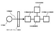
本発明で用いるインターフェース部分102とは、電磁波検出部103、位置演算部104、形状記憶部105などを内包する装置の筐体、素子の外殻、外殻の一部などを指し、インターフェース部分102を透過する電磁波106を用いて、情報のやり取りを行う場所である。インターフェース部分102の実例をあげるとすると、タッチパネルのディスプレイ部分、携帯電話やモバイルパソコン等のパッケージ部分、ボタンやスイッチといった個別素子に人が接触する部分を指す。ただし、これらに限定されるものではない。特に情報の入出力を扱う場合、図2に示すように、物体101とインターフェース部分102の相対的な位置関係についての情報によって、何らかのレスポンスを与えるための制御部として、情報入出力制御部201を更に内包してもよい。 The interface portion 102 used in the present invention refers to a housing of an apparatus including the electromagnetic wave detection unit 103, the position calculation unit 104, the shape memory unit 105, and the like, an outer shell of the element, a part of the outer shell, and the like. This is a place where information is exchanged by using the electromagnetic wave 106 that passes through. As an actual example of the interface portion 102, it indicates a portion where a person touches an individual element such as a display portion of a touch panel, a package portion such as a mobile phone or a mobile personal computer, a button or a switch. However, it is not limited to these. In particular, when handling input / output of information, as shown in FIG. 2, an information input / output control unit 201 is used as a control unit for giving some response according to information on the relative positional relationship between the object 101 and the interface portion 102. Further, it may be included.
典型的には、本発明で用いる電磁波106は、30GHzから30THzまでの周波数帯域のうち、任意の周波数帯を占有する電磁波である。この帯域の電磁波は、光の直進性(指向性)に加えて、物体を或る程度透過するという電磁波の性質を併せ持つことが知られている。また、人の手などの温度を有する物体は、例えば次式に示すように、プランクの式として、温度Tに依存した電磁波を放射することが知られている。
Bν(T)=(2hν3/c2)/{exp(hν/kT)-1}
ここで、Bν(T):分光放射輝度、h:プランク定数、ν:振動数、c:光速度、k:ボルツマン定数、T:物体の絶対温度、である。電磁波106を放出する物体101として、人体の一部を想定した場合、その人体の一部が有する絶対温度Tに応じた電磁波スペクトルが得られることを意味している。本実施形態では、物体として人体の一部を想定しているが、これに限るものではない。
Typically, the electromagnetic wave 106 used in the present invention is an electromagnetic wave that occupies an arbitrary frequency band in a frequency band from 30 GHz to 30 THz. It is known that electromagnetic waves in this band have the property of electromagnetic waves that pass through an object to some extent in addition to the straightness (directivity) of light. Further, it is known that an object having a temperature such as a human hand emits an electromagnetic wave depending on the temperature T as a Planck's equation as shown in the following equation, for example.
Bν (T) = (2hν 3 / c 2 ) / {exp (hν / kT) -1}
Here, Bν (T): spectral radiance, h: Planck constant, ν: frequency, c: speed of light, k: Boltzmann constant, T: absolute temperature of the object. Assuming that a part of the human body is assumed as the object 101 that emits the electromagnetic wave 106, it means that an electromagnetic spectrum corresponding to the absolute temperature T of the part of the human body is obtained. In the present embodiment, a part of the human body is assumed as the object, but the present invention is not limited to this.
インターフェース部分102を透過する電磁波106を検出する電磁波検出部103の構成例を図3、図4に示す。これらの図のように、電磁波検出部103は、典型的には、インターフェース部分102を透過する電磁波106を集光する集光部301または401と、集光された電磁波106の位置を検出する変位検出部302とで構成する。 A configuration example of the electromagnetic wave detection unit 103 that detects the electromagnetic wave 106 transmitted through the interface portion 102 is shown in FIGS. As shown in these figures, the electromagnetic wave detection unit 103 typically includes a light collecting unit 301 or 401 that collects the electromagnetic wave 106 that passes through the interface part 102, and a displacement that detects the position of the collected electromagnetic wave 106. The detection unit 302 is configured.
図3は、電磁波検出部103の電磁波106を集光させる集光部301として、透過型のレンズを用いた例を示している。この場合、電磁波106の集光スポットは、図のように、電磁波106の伝搬軸方向上に形成される。光学技術と同じように、一般に、この集光スポットは、電磁波106が集光部301に入射する角度に応じて、その位置が変化する。そのため、この電磁波106の集光スポットが生じる領域に変位検出部302を配置すると、変位検出部302上の集光スポットの位置と、集光部301と変位検出部302の位置関係から、集光部301から変位検出部302へ至る電磁波106の角度情報が得られる。この角度情報と、集光部301の電磁波106に対する屈折率を参照することで、集光スポットの位置情報を電磁波106の入射角度情報に変換することができる。 FIG. 3 shows an example in which a transmissive lens is used as the condensing unit 301 that condenses the electromagnetic wave 106 of the electromagnetic wave detecting unit 103. In this case, the focused spot of the electromagnetic wave 106 is formed on the propagation axis direction of the electromagnetic wave 106 as shown in the figure. Similar to the optical technique, generally, the position of this condensing spot changes depending on the angle at which the electromagnetic wave 106 enters the condensing unit 301. For this reason, when the displacement detection unit 302 is arranged in a region where the condensing spot of the electromagnetic wave 106 is generated, the light is condensed from the position of the condensing spot on the displacement detecting unit 302 and the positional relationship between the condensing unit 301 and the displacement detecting unit 302. The angle information of the electromagnetic wave 106 from the unit 301 to the displacement detection unit 302 is obtained. By referring to the angle information and the refractive index of the condensing unit 301 with respect to the electromagnetic wave 106, the position information of the condensing spot can be converted into the incident angle information of the electromagnetic wave 106.
図4は、電磁波検出部103の電磁波106を集光させる集光部401として、曲面を有する反射型ミラーを用いた例を示している。この場合、電磁波106の集光スポットは、図のように、電磁波106の伝搬軸から外れた場所に形成される。光学技術と同じように、一般に、この集光スポットは、電磁波106が集光部401に入射する角度に応じて、その位置が変化する。そのため、この電磁波106の集光スポットが生じる領域に変位検出部302を配置すると、変位検出部302上の集光スポットの位置と、集光部401と変位検出部302の位置関係から、集光部401から変位検出部302へ至る電磁波106の反射角度情報が得られる。そのため、この反射角度情報を参照することにより、集光スポットの位置情報を電磁波106の入射角度情報に変換することができる。 FIG. 4 shows an example in which a reflective mirror having a curved surface is used as the light collecting unit 401 for collecting the electromagnetic wave 106 of the electromagnetic wave detecting unit 103. In this case, the condensing spot of the electromagnetic wave 106 is formed at a location off the propagation axis of the electromagnetic wave 106 as shown in the figure. Similar to the optical technique, generally, the position of the condensing spot changes depending on the angle at which the electromagnetic wave 106 enters the condensing unit 401. For this reason, when the displacement detection unit 302 is arranged in a region where the condensing spot of the electromagnetic wave 106 is generated, the light is condensed from the position of the condensing spot on the displacement detecting unit 302 and the positional relationship between the condensing unit 401 and the displacement detecting unit 302. The reflection angle information of the electromagnetic wave 106 from the unit 401 to the displacement detection unit 302 is obtained. Therefore, by referring to the reflection angle information, the position information of the focused spot can be converted into the incident angle information of the electromagnetic wave 106.
例えば、変位検出部302として、少なくとも、電磁波106が有する周波数帯域幅に検出感度を持つ、複数のアンテナ素子から成るアンテナアレイと、各アンテナに対応して配置されるボロメータのような電磁波検出素子を用いた場合、電磁波106の集光スポットに対応するアンテナ素子、及び電磁波検出素子の強度をモニタすることにより、集光スポットの位置を検出する。変位検出部302の構成はこれに限るものではなく、例えば電磁波検出素子だけで構成することも可能である。 For example, as the displacement detection unit 302, an antenna array composed of a plurality of antenna elements having detection sensitivity in at least the frequency bandwidth of the electromagnetic wave 106, and an electromagnetic wave detection element such as a bolometer arranged corresponding to each antenna. When used, the position of the focused spot is detected by monitoring the intensity of the antenna element corresponding to the focused spot of the electromagnetic wave 106 and the electromagnetic wave detecting element. The configuration of the displacement detection unit 302 is not limited to this, and may be configured with only an electromagnetic wave detection element, for example.
上記いずれの方式も、インターフェース部分102を透過する電磁波106の入射角度を求める方法の一例を示したものであるが、これらの方式に限るものではない。 Each of the above-described methods shows an example of a method for obtaining the incident angle of the electromagnetic wave 106 transmitted through the interface portion 102, but is not limited to these methods.
形状記憶部105は、インターフェース部分102の形状を予め空間座標データとして記憶しておく装置である。インターフェース部分102の空間座標の基準座標は、電磁波106を放射する物体101とインターフェース部分102を介して対向する点、インターフェース部分102によって内包される任意の点などとする。 The shape storage unit 105 is a device that previously stores the shape of the interface portion 102 as spatial coordinate data. The reference coordinates of the spatial coordinates of the interface portion 102 are a point facing the object 101 that emits the electromagnetic wave 106 via the interface portion 102, an arbitrary point included by the interface portion 102, and the like.
位置演算部104は、電磁波検出部103より得られるインターフェース部分102を透過する電磁波106の入射角度情報と集光スポットの強度情報、インターフェース部分102を透過する電磁波106に対する複数の入射角度情報などより、物体101の空間位置座標を演算する。さらに、位置演算部104では、演算した物体101の空間位置座標を、形状記憶部105に予め記憶されているインターフェース部分102の空間座標データを参照して、インターフェース部分102に対する物体101の相対的な位置情報に変換して出力する。 The position calculation unit 104 is obtained from the incident angle information of the electromagnetic wave 106 transmitted through the interface part 102 obtained from the electromagnetic wave detection unit 103 and the intensity information of the focused spot, a plurality of incident angle information for the electromagnetic wave 106 transmitted through the interface part 102, etc. The spatial position coordinates of the object 101 are calculated. Further, in the position calculation unit 104, the calculated spatial position coordinates of the object 101 are referred to the spatial coordinate data of the interface part 102 stored in advance in the shape storage unit 105, and the relative position of the object 101 with respect to the interface part 102 is determined. Convert to location information and output.
以下に、実際のインターフェース部分102に対する物体101の相対的な位置情報の検出方法、及び空間位置検出装置の構成例について、図5、図6、図7、図8を用いて説明する。ここでは、物体101の空間座標を表す方法として、図示するように、集光部301を原点として、紙面に対して法線方向をx軸、縦方向をy軸、横方向をz軸で表す。また、原点である集光部301に対して、xy平面になす角をθ、xz平面になす角をφと表現する。 Hereinafter, a method for detecting relative position information of the object 101 with respect to the actual interface portion 102 and a configuration example of the spatial position detection device will be described with reference to FIGS. 5, 6, 7, and 8. Here, as a method for representing the spatial coordinates of the object 101, as shown in the drawing, the normal direction is represented by the x axis, the vertical direction is represented by the y axis, and the horizontal direction is represented by the z axis with respect to the paper surface as the origin. . In addition, with respect to the light collecting unit 301 that is the origin, an angle formed on the xy plane is expressed as θ, and an angle formed on the xz plane is expressed as φ.
図5において、物体101として人体を用い、インターフェース部分102として装置の筐体を用いる。そのため、実際には、集光部301、変位検出部302は、筐体内部に存在する。変位検出部302としては、アンテナアレイと複数の電磁波検出素子を用いる。アンテナアレイの感度は、人体より放射する電磁波の帯域中に存在するように設計する。集光部301としては、シリコンレンズを用いる。装置構成については、これに限るものではない。集光部301と変位検出部302は、各素子の中心を通る線kに沿って、距離Lだけ離れて配置されている。 In FIG. 5, a human body is used as the object 101, and a housing of the apparatus is used as the interface portion 102. Therefore, actually, the light collecting unit 301 and the displacement detection unit 302 exist inside the housing. As the displacement detection unit 302, an antenna array and a plurality of electromagnetic wave detection elements are used. The sensitivity of the antenna array is designed to exist in the band of electromagnetic waves radiated from the human body. As the light condensing unit 301, a silicon lens is used. The device configuration is not limited to this. The condensing unit 301 and the displacement detection unit 302 are arranged at a distance L along a line k passing through the center of each element.
図5では、インターフェース部分102付近に存在する物体101の空間位置座標(X,Y,Z)を検出するために、一組の集光部301と変位検出部302を用いる。物体101は、人体であるため、電磁波106を自然放出している。この電磁波106は、インターフェース部分102と集光部301を介して変位検出部302に集光スポットを形成する。この電磁波106の集光スポットは、変位検出部302を構成するアンテナアレイと複数の電磁波検出素子の強度分布を参照することで特定する。そして、アンテナアレイを構成する各アンテナに対応する電磁波検出素子の信号強度をモニタし、最も強い出力信号を出している電磁波検出素子の位置を集光スポットの中心位置(x,y)とする。ここで、(x,y)は、変位検出部302の中心を原点(0,0)とする座標を表している。この中心座標は、上述した中心線kを通る線上にある点とする。集光部301と変位検出部302の距離Lは既知のものなので、集光スポットの中心位置(x,y)と距離Lによって、集光部301から変位検出部302へ至る電磁波106の出射角度(θ’,φ’)を求めることができる。上述したように、集光部301は透過型のレンズであるシリコンレンズで構成するため、レンズからの出射角度(θ’,φ’)がわかれば、レンズへの入射角度、すなわち、物体101から放射する電磁波106の入射角度(θ,φ)を求めることが可能になる。 In FIG. 5, in order to detect the spatial position coordinates (X, Y, Z) of the object 101 existing in the vicinity of the interface portion 102, a pair of condensing unit 301 and displacement detecting unit 302 are used. Since the object 101 is a human body, the electromagnetic wave 106 is spontaneously emitted. The electromagnetic wave 106 forms a condensing spot on the displacement detection unit 302 via the interface part 102 and the condensing unit 301. The condensing spot of the electromagnetic wave 106 is specified by referring to the antenna array that constitutes the displacement detection unit 302 and the intensity distribution of the plurality of electromagnetic wave detection elements. Then, the signal intensity of the electromagnetic wave detection element corresponding to each antenna constituting the antenna array is monitored, and the position of the electromagnetic wave detection element that outputs the strongest output signal is set as the center position (x, y) of the focused spot. Here, (x, y) represents coordinates with the center of the displacement detection unit 302 as the origin (0, 0). The center coordinates are points on the line passing through the center line k described above. Since the distance L between the condensing unit 301 and the displacement detecting unit 302 is known, the emission angle of the electromagnetic wave 106 from the condensing unit 301 to the displacement detecting unit 302 depending on the center position (x, y) of the condensing spot and the distance L. (θ ′, φ ′) can be obtained. As described above, since the condensing unit 301 is configured by a silicon lens that is a transmissive lens, if the emission angle (θ ′, φ ′) from the lens is known, the incident angle to the lens, that is, from the object 101 The incident angle (θ, φ) of the radiated electromagnetic wave 106 can be obtained.
変位検出部302で検出する集光スポットの強度信号Aは、物体101から放射する電磁波106の伝搬距離によって変化する。そのため、電磁波106の入射角度(θ,φ)と集光スポットの信号強度Aより、物体101の空間位置座標(X,Y,Z)を求めることができる。また、使用する物体101によって得られる信号強度Aが異なる場合があるため、使用開始時に、既知の場所、例えばインターフェース部分102の特定の場所における物体101の強度信号と伝搬距離の関係を測定しておいて、集光スポットの強度信号Aと電磁波の伝搬距離の関係に補正をかける構成を有していてもよい。その後、位置演算部104は、形状記憶部105に予め記憶されているインターフェース部分102の空間座標データを参照し、物体101の空間位置座標(X,Y,Z)を通過するインターフェース部分102に立てた法線のうち、最も距離が短い法線がインターフェース部分102と交わる交点を選択し、この点に対する物体101の相対的な位置情報を算出する。 The intensity signal A of the focused spot detected by the displacement detector 302 changes depending on the propagation distance of the electromagnetic wave 106 radiated from the object 101. Therefore, the spatial position coordinates (X, Y, Z) of the object 101 can be obtained from the incident angle (θ, φ) of the electromagnetic wave 106 and the signal intensity A of the focused spot. In addition, since the signal intensity A obtained may vary depending on the object 101 to be used, the relationship between the intensity signal of the object 101 and the propagation distance at a known location, for example, a specific location of the interface portion 102, is measured at the start of use. In addition, you may have the structure which correct | amends the relationship between the intensity signal A of a condensing spot, and the propagation distance of electromagnetic waves. Thereafter, the position calculation unit 104 refers to the spatial coordinate data of the interface portion 102 stored in advance in the shape storage unit 105, and stands on the interface portion 102 that passes through the spatial position coordinates (X, Y, Z) of the object 101. Among the normals, an intersection where the normal with the shortest distance intersects the interface portion 102 is selected, and relative position information of the object 101 with respect to this point is calculated.
このようにして、本実施形態の空間位置検出装置では、インターフェース部分102付近に存在する物体101の空間位置座標を検出し、これをインターフェース部分102に対する物体101の相対的な位置情報に変換できる。 In this manner, the spatial position detection device of the present embodiment can detect the spatial position coordinates of the object 101 existing in the vicinity of the interface portion 102 and convert this into positional information of the object 101 relative to the interface portion 102.
図6は、インターフェース部分102に対する物体101の相対的な位置情報の検出方法、及び空間位置検出装置に関して、別の構成例を示したものである。 FIG. 6 shows another configuration example regarding a method for detecting positional information of the object 101 relative to the interface portion 102 and a spatial position detecting device.
図6においても、物体101として人体を用い、インターフェース部分102として装置の筐体を用いる。集光部301と変位検出部302についても、図5の例と同じである。集光部301と変位検出部302は、各素子の中心を通る線k、lに沿って、距離Lだけ離れて配置されている。 Also in FIG. 6, a human body is used as the object 101, and a housing of the apparatus is used as the interface portion 102. The condensing unit 301 and the displacement detection unit 302 are also the same as the example in FIG. The condensing unit 301 and the displacement detection unit 302 are arranged apart from each other by a distance L along lines k and l passing through the center of each element.
図6では、インターフェース部分102付近に存在する物体101の空間位置座標(X,Y,Z)を検出するために、二組の集光部301と変位検出部302を用いる。物体101から自然放出している電磁波106は、インターフェース部分102と二つの集光部301を介して二つの変位検出部302に集光スポットを形成する。この電磁波106の集光スポットは、変位検出部302を構成するアンテナアレイと複数の電磁波検出素子の強度分布を参照することで特定する。そして、アンテナアレイを構成する各アンテナに対応する電磁波検出素子の信号強度をモニタし、最も強い出力信号を出している電磁波検出素子の位置を集光スポットの中心位置(x1,y1)、(x2,y2)とする。ここで、(x1,y1)、(x2,y2)は、変位検出部302の中心を原点(0,0)とする座標を表している。この中心座標は、上述した中心線k、lをそれぞれ通る線上にある点とする。集光部301と変位検出部302の距離Lは既知のものなので、集光スポットの中心位置(x1,y1)、(x2,y2)と距離Lによって、集光部301から変位検出部302へ至る電磁波106の出射角度(θ1’,φ1’)、(θ2’,φ2’)を求めることができる。集光部301は透過型のレンズであるシリコンレンズで構成するため、レンズからの出射角度(θ1’,φ1’)、(θ2’,φ2’)がわかれば、レンズへの入射角度、すなわち、物体101から放射する電磁波106の入射角度(θ1,φ1)、(θ2,φ2)をそれぞれ求めることが可能になる。 In FIG. 6, in order to detect the spatial position coordinates (X, Y, Z) of the object 101 existing in the vicinity of the interface portion 102, two sets of the condensing unit 301 and the displacement detection unit 302 are used. The electromagnetic wave 106 spontaneously emitted from the object 101 forms a condensing spot on the two displacement detectors 302 via the interface part 102 and the two condensing parts 301. The condensing spot of the electromagnetic wave 106 is specified by referring to the antenna array that constitutes the displacement detection unit 302 and the intensity distribution of the plurality of electromagnetic wave detection elements. Then, the signal intensity of the electromagnetic wave detection element corresponding to each antenna constituting the antenna array is monitored, and the position of the electromagnetic wave detection element that outputs the strongest output signal is set to the center position of the focused spot (x 1 , y 1 ), Let (x 2 , y 2 ). Here, (x 1 , y 1 ) and (x 2 , y 2 ) represent coordinates having the center of the displacement detection unit 302 as the origin (0, 0). The center coordinates are points on the lines passing through the center lines k and l described above. Since the distance L between the condensing unit 301 and the displacement detecting unit 302 is known, it is displaced from the condensing unit 301 according to the center position (x 1 , y 1 ), (x 2 , y 2 ) of the condensing spot and the distance L. The emission angles (θ 1 ′, φ 1 ′) and (θ 2 ′, φ 2 ′) of the electromagnetic wave 106 reaching the detection unit 302 can be obtained. The condensing part 301 is composed of a silicon lens that is a transmissive lens, so if the exit angle (θ 1 ′, φ 1 ′), (θ 2 ′, φ 2 ′) from the lens is known, it is incident on the lens. The angles, that is, the incident angles (θ 1 , φ 1 ) and (θ 2 , φ 2 ) of the electromagnetic wave 106 radiated from the object 101 can be obtained.
本実施形態では、各集光部301から物体101へ至る複数の角度を求めることで、物体101の位置を知ることができる。ここでは、各集光部301へ入射する電磁波106の二つの入射角度(θ1,φ1)、(θ2,φ2)より、三角測量法を用いて、物体101の空間位置座標(X,Y,Z)を求めることができる。その後、位置演算部104は、形状記憶部105に予め記憶されているインターフェース部分102の空間座標データを参照し、物体101の空間位置座標(X,Y,Z)を通過するインターフェース部分102に立てた法線のうち、最も距離が短い法線がインターフェース部分102と交わる交点を選択し、この点に対する物体101の相対的な位置情報を算出する。 In the present embodiment, the position of the object 101 can be known by obtaining a plurality of angles from each condensing unit 301 to the object 101. Here, from the two incident angles (θ 1 , φ 1 ), (θ 2 , φ 2 ) of the electromagnetic wave 106 incident on each condensing unit 301, the spatial position coordinates (X , Y, Z). Thereafter, the position calculation unit 104 refers to the spatial coordinate data of the interface portion 102 stored in advance in the shape storage unit 105, and stands on the interface portion 102 that passes through the spatial position coordinates (X, Y, Z) of the object 101. Among the normals, an intersection where the normal with the shortest distance intersects the interface portion 102 is selected, and relative position information of the object 101 with respect to this point is calculated.
このようにして、本実施形態の空間位置検出装置でも、インターフェース部分102付近に存在する物体101の空間位置座標を検出し、これをインターフェース部分102に対する物体101の相対的な位置情報に変換することができる。 In this way, the spatial position detection device of the present embodiment also detects the spatial position coordinates of the object 101 existing in the vicinity of the interface portion 102, and converts this into positional information of the object 101 relative to the interface portion 102. Can do.
図7は、インターフェース部分102に対する物体101の相対的な位置情報の検出方法、及び空間位置検出装置に関して、さらに別の構成例を示したものである。 FIG. 7 shows still another configuration example regarding a method for detecting positional information of the object 101 relative to the interface portion 102 and a spatial position detecting device.
図7でも、物体101として人体を用い、インターフェース部分102として装置の筐体を用いる。変位検出部302は図5のものと同じである。集光部401としては、軸はずし放物面鏡を用いる。装置構成については、これに限るものではない。変位検出部302は、集光部401の中心を通る線kと変位検出部302の中心を通る線mとの交点から、中心線mに沿って、距離Lだけ離れて配置されている。 Also in FIG. 7, a human body is used as the object 101 and a housing of the apparatus is used as the interface portion 102. The displacement detector 302 is the same as that shown in FIG. As the light collecting unit 401, an off-axis parabolic mirror is used. The device configuration is not limited to this. The displacement detection unit 302 is arranged at a distance L from the intersection of the line k passing through the center of the light collecting unit 401 and the line m passing through the center of the displacement detection unit 302 along the center line m.
図7では、インターフェース部分102付近に存在する物体101の空間位置座標(X,Y,Z)を検出するため、一組の集光部401と変位検出部302を用いる。集光スポットの中心位置(x,y)の求め方は図5の場合と同じである。集光部401と変位検出部302の距離Lは既知のものなので、集光スポットの中心位置(x,y)と距離Lによって、集光部401から変位検出部302へ至る電磁波106の反射角度(θ’,φ’)を求めることができる。上述したように、集光部401は曲面を有する反射型のミラーである軸はずし放物面鏡で構成するため、ミラーからの反射角度(θ’,φ’)がわかれば、ミラーへの入射角度、すなわち、物体101から放射する電磁波106の入射角度(θ,φ)を求めることが可能になる。 In FIG. 7, in order to detect the spatial position coordinates (X, Y, Z) of the object 101 existing in the vicinity of the interface portion 102, a pair of condensing unit 401 and displacement detection unit 302 is used. The method for obtaining the center position (x, y) of the focused spot is the same as in FIG. Since the distance L between the condensing unit 401 and the displacement detecting unit 302 is known, the reflection angle of the electromagnetic wave 106 from the condensing unit 401 to the displacement detecting unit 302 depending on the center position (x, y) of the condensing spot and the distance L. (θ ′, φ ′) can be obtained. As described above, the condensing unit 401 is composed of an off-axis paraboloidal mirror that is a reflective mirror having a curved surface. Therefore, if the reflection angle (θ ′, φ ′) from the mirror is known, the light is incident on the mirror. The angle, that is, the incident angle (θ, φ) of the electromagnetic wave 106 radiated from the object 101 can be obtained.
インターフェース部分102に対する物体101の相対的な位置情報の算出方法は図5の実施形態で説明した通りである。このようにして、本実施形態の空間位置検出装置でも、インターフェース部分102付近に存在する物体101の空間位置座標を検出し、インターフェース部分102に対する物体101の相対的な位置情報に変換することができる。 The method for calculating the relative position information of the object 101 with respect to the interface portion 102 is as described in the embodiment of FIG. In this way, the spatial position detection device of the present embodiment can also detect the spatial position coordinates of the object 101 existing in the vicinity of the interface portion 102 and convert it into relative position information of the object 101 with respect to the interface portion 102. .
図8は、インターフェース部分102に対する物体101の相対的な位置情報の検出方法、及び空間位置検出装置に関して、さらに別の構成例を示したものである。 FIG. 8 shows still another configuration example regarding the method for detecting the positional information of the object 101 relative to the interface portion 102 and the spatial position detecting device.
図8においても、物体101として人体を用い、インターフェース部分102として装置の筐体を用いる。集光部401と変位検出部302の装置構成は、図7のものと同じである。変位検出部302は、集光部401の中心を通る線k、lと変位検出部302の中心を通る線m、nとの交点から、中心線m、nに沿って、距離Lだけ離れて配置されている。 Also in FIG. 8, a human body is used as the object 101, and a housing of the apparatus is used as the interface portion 102. The apparatus configuration of the light collecting unit 401 and the displacement detecting unit 302 is the same as that in FIG. The displacement detection unit 302 is separated by a distance L along the center lines m and n from the intersection of the lines k and l passing through the center of the light collecting unit 401 and the lines m and n passing through the center of the displacement detection unit 302. Has been placed.
図8では、インターフェース部分102付近に存在する物体101の空間位置座標(X,Y,Z)を検出するために、二組の集光部401と変位検出部302を用いる。電磁波検出素子上の集光スポットの中心位置(x1,y1)、(x2,y2)の求め方は上記実施形態で説明した通りである。また、集光スポットの中心位置(x1,y1)、(x2,y2)と距離Lによって、集光部401から変位検出部302へ至る電磁波106の反射角度(θ1’,φ1’)、(θ2’,φ2’)を求め、ミラーへの入射角度、すなわち、物体101から放射する電磁波106の入射角度(θ1,φ1)、(θ2,φ2)を求める方法は図6の例で説明したものと実質的に同じである。物体101の相対的な位置情報を算出する方法も図6の例で説明した通りである。 In FIG. 8, in order to detect the spatial position coordinates (X, Y, Z) of the object 101 existing in the vicinity of the interface portion 102, two sets of the condensing unit 401 and the displacement detection unit 302 are used. The method for obtaining the center positions (x 1 , y 1 ) and (x 2 , y 2 ) of the focused spot on the electromagnetic wave detection element is as described in the above embodiment. In addition, the reflection angle (θ 1 ′, φ) of the electromagnetic wave 106 from the condensing unit 401 to the displacement detecting unit 302 according to the center position (x 1 , y 1 ), (x 2 , y 2 ) and the distance L of the condensing spot. 1 ′), (θ 2 ′, φ 2 ′), and determine the incident angle to the mirror, that is, the incident angle (θ 1 , φ 1 ), (θ 2 , φ 2 ) of the electromagnetic wave 106 radiated from the object 101 The method of obtaining is substantially the same as that described in the example of FIG. The method for calculating the relative position information of the object 101 is also as described in the example of FIG.
このようにして、本実施形態の空間位置検出装置でも、インターフェース部分102付近に存在する、物体101の空間位置座標を検出し、インターフェース部分102に対する物体101の相対的な位置情報に変換することができる。 In this way, the spatial position detection device of the present embodiment can also detect the spatial position coordinates of the object 101 existing in the vicinity of the interface portion 102 and convert it into relative position information of the object 101 with respect to the interface portion 102. it can.
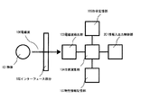
次に、図9に本発明の物体の空間位置検出装置の更なる他の実施形態に関するブロック図を示す。図9の実施形態は、図1の構成に加えて、インターフェース部分102の物性の分布情報を記憶しておく物性情報記憶部107を備える。この物性とは、インターフェース部分102が有する形状(厚み分布など)、誘電率、電磁波吸収率などの特性であるが、これに限るものではない。 Next, FIG. 9 shows a block diagram relating to still another embodiment of the object spatial position detection apparatus of the present invention. The embodiment of FIG. 9 includes a physical property information storage unit 107 that stores physical property distribution information of the interface portion 102 in addition to the configuration of FIG. The physical properties are characteristics such as the shape (thickness distribution, etc.), dielectric constant, electromagnetic wave absorption rate, and the like of the interface portion 102, but are not limited thereto.
本実施形態の特徴は以下のごときものである。電磁波106が透過するインターフェース部分102、またはその一部分が、或る誘電性の物質で構成される場合や、或いは電磁波吸収性の物質で構成されているとする。こうしてインターフェース部分102の周辺環境が変化すると、インターフェース部分102を透過する電磁波106の伝搬特性は変化する。例えば、図11のように、インターフェース部分102が、或る厚さを有する誘電性の物質で構成される場合、インターフェース部分102に入射する電磁波106は、インターフェース部分102を透過する過程で屈折し、電磁波検出部103へ至る伝搬経路が変化する。この現象は、特にインターフェース部分102の周辺部にいくほど、影響が大きくなる。この伝搬経路の変化は、物体101の位置情報において誤差の原因となることが考えられる。そこで本実施形態では、位置演算部104で求められた物体101の空間位置座標に関して、物性情報記憶部107を参照し、インターフェース部分102の物性の分布情報を取得し、そこから得られる電磁波106の伝搬特性への影響を考慮し、演算結果に対して補正をかける。こうして、より正確な物体101の位置情報を求めるような構成を有する。 The features of this embodiment are as follows. Assume that the interface portion 102 through which the electromagnetic wave 106 is transmitted, or a part thereof, is made of a certain dielectric material, or is made of an electromagnetic wave absorbing material. Thus, when the surrounding environment of the interface portion 102 changes, the propagation characteristics of the electromagnetic wave 106 that passes through the interface portion 102 change. For example, as shown in FIG. 11, when the interface portion 102 is made of a dielectric material having a certain thickness, the electromagnetic wave 106 incident on the interface portion 102 is refracted in the process of passing through the interface portion 102, The propagation path to the electromagnetic wave detection unit 103 changes. This phenomenon has a greater effect especially in the periphery of the interface portion 102. This change in the propagation path may cause an error in the position information of the object 101. Therefore, in the present embodiment, with respect to the spatial position coordinates of the object 101 obtained by the position calculation unit 104, the physical property information storage unit 107 is referred to obtain physical property distribution information of the interface part 102, and the electromagnetic wave 106 obtained therefrom is obtained. The calculation result is corrected in consideration of the influence on the propagation characteristics. In this way, a more accurate position information of the object 101 is obtained.
この考え方は、上記実施形態の全てに適用できる。例えば、図6のように、物体101の位置を三角測量法によって求める装置の場合、インターフェース部分102が、或る厚みを有する誘電性の物質で構成され、図11のように、電磁波106の伝搬経路が変化するものとする。こうした場合、図6の電磁波106の各伝搬経路について、物性情報記憶部107に記憶されているインターフェース部分107の誘電率と厚さの情報を参照し、屈折の影響を考慮した形に変換し、物体101の位置情報に対して補正をかける。図5のように、物体101から放射する電磁波106の伝搬距離によって変化する集光スポットの強度信号を用いる場合も、必要であれば、インターフェース部分102の透過部分の電磁波吸収率の情報を参照して、物体101の位置情報に対して補正をかければよい。 This concept can be applied to all of the above embodiments. For example, in the case of a device that obtains the position of the object 101 by triangulation as shown in FIG. 6, the interface portion 102 is made of a dielectric material having a certain thickness, and the propagation of the electromagnetic wave 106 as shown in FIG. Assume that the route changes. In such a case, for each propagation path of the electromagnetic wave 106 in FIG. 6, referring to information on the dielectric constant and thickness of the interface portion 107 stored in the physical property information storage unit 107, it is converted into a form that takes into account the influence of refraction, The position information of the object 101 is corrected. As shown in FIG. 5, when using the intensity signal of the condensing spot that varies depending on the propagation distance of the electromagnetic wave 106 radiated from the object 101, if necessary, refer to the information on the electromagnetic wave absorption rate of the transmission part of the interface part 102. Thus, the position information of the object 101 may be corrected.
以下、上述した空間位置検出装置を、図2や図10に示したような情報入力装置へ適応した実施例を示す。ここでは、情報入出力制御部201を用いて、物体101とインターフェース部分102の相対的な位置関係についての情報より情報や信号の操作を行う。 Hereinafter, an embodiment in which the above-described spatial position detection device is applied to an information input device as shown in FIG. 2 or FIG. 10 will be described. Here, the information input / output control unit 201 is used to operate information and signals from information on the relative positional relationship between the object 101 and the interface portion 102.
(実施例1)
ここでは、上述した情報入力装置として、携帯電話やモバイルコンピュータ等の携帯型の情報端末装置への適応例を説明する。図12に本実施例における携帯型の情報端末装置の構成を示す。ここでは、説明の都合上、携帯電話を用いるが、これに限るものではない。本実施例では、物体101として、人体の一部を用い、インターフェース部分102として、携帯型の情報端末装置の筐体を用いる。また、情報入力装置の構成要素である、電磁波検出部103、位置演算部104、形状記憶部105、情報入出力制御部201(更には物性情報記憶部105)は、携帯型の情報端末装置の筐体に内包されている。
(Example 1)
Here, an example of application to a portable information terminal device such as a mobile phone or a mobile computer will be described as the information input device described above. FIG. 12 shows the configuration of a portable information terminal device in this embodiment. Here, for convenience of explanation, a mobile phone is used, but the present invention is not limited to this. In this embodiment, a part of a human body is used as the object 101, and a casing of a portable information terminal device is used as the interface portion 102. Further, the electromagnetic wave detection unit 103, the position calculation unit 104, the shape storage unit 105, and the information input / output control unit 201 (and further the physical property information storage unit 105), which are constituent elements of the information input device, are included in the portable information terminal device. Enclosed in a housing.
上述したように、形状記憶部105は、筐体の外形情報を予め記憶している。さらに、本実施例のように、情報端末装置として使用する場合、筐体を構成する要素(入力ボタン、ディスプレイ部、受話部等)の位置情報を、情報入出力制御部201と共有する。情報入出力制御部201では、筐体を構成する各要素と、人体の一部との相対的な距離関係についての情報をモニタし、距離関係情報に応じて携帯型の情報端末装置の動作を制御する。この相対的な距離関係は、上述したように、人体の一部より放射される電磁波106を用いて検出する。また、人体の一部は、必要に応じて、人体の一部を加熱する機能を有する加熱物体を装着してもよい。 As described above, the shape storage unit 105 stores the external shape information of the housing in advance. Further, as in the present embodiment, when used as an information terminal device, the position information of elements (input button, display unit, receiving unit, etc.) constituting the housing is shared with the information input / output control unit 201. The information input / output control unit 201 monitors information on the relative distance relationship between each element constituting the housing and a part of the human body, and operates the portable information terminal device according to the distance relationship information. Control. This relative distance relationship is detected using the electromagnetic wave 106 radiated from a part of the human body as described above. Further, a part of the human body may be equipped with a heating object having a function of heating a part of the human body as necessary.
例えば、図12のように、筐体の構成要素のうち、『2』に相当する入力ボタンに指101が接近した時、情報入出力制御部201は、入力ボタンと指先の相対的な距離関係をモニタし、一定の距離を下回った(或いは接触した)場合に入力状態とするといったように、情報の入力を行う。場合によって、ディスプレイ部にその情報を表示することもできる。 For example, as shown in FIG. 12, when the finger 101 approaches the input button corresponding to “2” among the components of the housing, the information input / output control unit 201 determines the relative distance relationship between the input button and the fingertip. Is input, and information is input such that the input state is entered when the distance falls below (or touches) a certain distance. In some cases, the information can be displayed on the display unit.
また、筐体の構成要素のうち、受話部に耳101が接近した時、情報入出力制御部201は、受話部と耳の相対的な距離関係をモニタし、一定の距離を下回った(或いは接触した)場合に受話可能状態にするなど、携帯型の情報端末装置の動作を制御することもできる。 Of the components of the housing, when the ear 101 approaches the receiver, the information input / output controller 201 monitors the relative distance relationship between the receiver and the ear and falls below a certain distance (or It is also possible to control the operation of the portable information terminal device, such as making it possible to receive a call when contacted.
また、筐体に、或る一定時間、人体からの電磁波106の放射がなかった場合、つまり、この携帯型の情報端末装置が使用されていない場合、この相対的な距離関係の時間変化態様をモニタし省電力モードにするなど、携帯型の情報端末装置の取り巻く環境状況によって動作を制御することもできる。 Further, when the case has not been irradiated with electromagnetic waves 106 from the human body for a certain period of time, that is, when this portable information terminal device is not used, the time variation mode of this relative distance relationship is changed. The operation can also be controlled according to the environmental situation surrounding the portable information terminal device, such as monitoring and setting the power saving mode.
上記構成において、物性情報記憶部107を備える場合は次の様にできる。物性情報記憶部107では、筐体や筐体を構成する要素に関する物性の分布情報を予め記憶しており、必要に応じて、人体の一部の位置情報について、補正をかけている。例えば、インターフェース部分102の数箇所に接触させてゼロ点補正することが手段として考えられる。また、筐体に対して、アクセサリを添付したり、ペイントを施したり、筐体を保管するカバーを別途装着するなど、インターフェース部分102を取り巻く環境が変化した場合、再度、物性分布情報を取得し直す機能を有していたり、または、アクセサリやカバーのように頻繁に取り外しするような物の場合には、カバーの有無によって物性分布情報を切り替える機能を有していてもよい。また、操作する物体101の個体差に対しての補正をかける機能を有していてもよい。 In the above configuration, when the physical property information storage unit 107 is provided, it can be performed as follows. The physical property information storage unit 107 stores physical property distribution information related to the housing and the elements constituting the housing in advance, and corrects position information of a part of the human body as necessary. For example, it is conceivable as a means to perform zero point correction by contacting several portions of the interface portion 102. Also, if the environment surrounding the interface part 102 changes, such as attaching accessories to the housing, painting, or attaching a cover to store the housing separately, acquire physical property distribution information again. In the case of an object that is frequently removed, such as an accessory or a cover, it may have a function of switching physical property distribution information depending on the presence or absence of a cover. Further, it may have a function of correcting the individual difference of the object 101 to be operated.
(実施例2)
ここでは、上述した情報入力装置として、PDA(Personal Digital Assistance)のような携帯型の情報端末装置のうち、ペン入力機能を伴う情報端末装置への適応例を示す。図13に本実施例におけるペン入力機能を伴う情報端末装置の構成を示す。本実施例では、物体101として、電磁波106を放射するペンを用いる。また、インターフェース部分102として、ペン入力機能を伴う情報端末装置の筐体を用いる。また、情報入力装置の構成要素である電磁波検出部103、位置演算部104、形状記憶部105、情報入出力制御部201(更には物性情報記憶部105)は、ペン入力機能を伴う情報端末装置の筐体に内包されている。
(Example 2)
Here, an example of adaptation to an information terminal device having a pen input function among portable information terminal devices such as a PDA (Personal Digital Assistance) is shown as the information input device described above. FIG. 13 shows the configuration of an information terminal device with a pen input function in this embodiment. In this embodiment, a pen that radiates an electromagnetic wave 106 is used as the object 101. Further, as the interface portion 102, a housing of an information terminal device with a pen input function is used. In addition, the electromagnetic wave detection unit 103, the position calculation unit 104, the shape storage unit 105, and the information input / output control unit 201 (and further the physical property information storage unit 105), which are components of the information input device, are information terminal devices with a pen input function. It is enclosed in the case.
上述したように、形状記憶部105は、筐体の外形情報を予め記憶している。さらに、本実施例のように、ペン入力機能を伴う情報端末装置として使用する場合、ディスプレイ部などの書き込み可能領域と不可領域の位置情報を、情報入出力制御部201と共有する。また、情報入出力制御部201では、ディスプレイ上に表示されているGUI(Graphical User
Interface)の位置情報を管理している。そして、情報入出力制御部201では、書き込み可能領域とペン先との相対的な距離関係をモニタし、距離関係情報に応じて、情報の操作を行う。この相対的な距離関係は、上述したように、ペン先より放射される電磁波106を用いて検出する。また、ペンは、必要に応じて、ペン先を加熱する機能を有していてもよい。
As described above, the shape storage unit 105 stores the external shape information of the housing in advance. Further, when used as an information terminal device with a pen input function as in the present embodiment, the position information of the writable area and the unusable area such as the display unit is shared with the information input / output control unit 201. The information input / output control unit 201 also displays a GUI (Graphical User) displayed on the display.
Interface) location information is managed. Then, the information input / output control unit 201 monitors the relative distance relationship between the writable area and the pen tip, and operates the information according to the distance relationship information. As described above, this relative distance relationship is detected using the electromagnetic wave 106 radiated from the pen tip. Moreover, the pen may have a function of heating the pen tip as necessary.
例えば、図13のように、ディスプレイ上に表示されているGUIのうち、『OK』ボタン領域にペン先が接近した時、情報入出力制御部201は、該ボタン領域とペン先の相対的な距離関係をモニタし、一定の距離を下回った(或いは接触した)場合に選択状態とし、所定の動作を行うように、GUIの動作を制御する。また、ドラッグ、ダブルクリックなどの機能も、選択状態と非選択状態の組み合わせにより、使用可能である。 For example, as shown in FIG. 13, when the pen tip approaches the “OK” button area in the GUI displayed on the display, the information input / output control unit 201 makes the relative relationship between the button area and the pen tip. The distance relationship is monitored, and the operation of the GUI is controlled so that a predetermined state is performed when the distance is less than (or touches) a certain distance. Also, functions such as dragging and double-clicking can be used by combining the selected state and the non-selected state.
また、ディスプレイ上に情報を入力する場合、ディスプレイ上の入力可能領域にペン先が接近した時、情報入出力制御部201は、入力可能領域とペン先の相対的な距離関係をモニタし、一定の距離を下回った(或いは接触した)場合に入力可能状態とし、情報の入力を行うなど、情報の入出力状態を制御する。特に、情報が入力可能状態である時、ペン先の位置によって、例えば押し込んだ時に線が太くなる、または色が濃くなるなどの制御を直感的に行うことも可能である。 In addition, when inputting information on the display, when the pen tip approaches the input possible area on the display, the information input / output control unit 201 monitors the relative distance relationship between the input possible area and the pen tip and keeps constant. When the distance is less than (or touched), the input is enabled, and the information input / output state is controlled such as inputting information. In particular, when information can be input, it is possible to intuitively perform control such that the line becomes thicker or the color becomes darker when pressed, depending on the position of the pen tip.
上記構成においても、物性情報記憶部107を備える場合は次の様にできる。物性情報記憶部107では、筐体における書き込み可能領域に関する物性の分布情報を予め記憶しており、必要に応じて、ペン先の位置情報について、補正をかけている。例えば、インターフェース部分102の数箇所に接触させてゼロ点補正することが手段として考えられる。また、書き込み可能領域に対して、保護シート貼ったり、筐体を保管するカバーを別途装着するなど、インターフェース部分102を取り巻く環境が変化した場合、再度、分布情報を取得し直す機能を有していたり、または、カバーのように頻繁に取り外しするような物の場合には、カバーの有無によって分布情報を切り替える機能を有していてもよい。また、操作する物体101の個体差に対しての補正をかける機能を有していてもよい。 Also in the above configuration, when the physical property information storage unit 107 is provided, it can be performed as follows. The physical property information storage unit 107 stores in advance physical property distribution information related to the writable area in the housing, and corrects the position information of the pen nib as necessary. For example, it is conceivable as a means to perform zero point correction by contacting several portions of the interface portion 102. In addition, if the environment surrounding the interface part 102 changes, such as attaching a protective sheet to the writable area or attaching a separate cover to store the housing, it has a function to re-acquire distribution information. In the case of an object that is frequently removed, such as a cover, it may have a function of switching distribution information depending on the presence or absence of a cover. Further, it may have a function of correcting the individual difference of the object 101 to be operated.
(実施例3)
ここでは、上述した情報入力装置として、テレビやパソコン、及びその他タッチパネルを有するディスプレイ装置への適応例を示す。図14に、本実施例におけるディスプレイ装置として、テレビにタッチパネル機能を付加した情報入力装置の構成を示す。本実施例では、物体101として、人体の一部を用いる。また、インターフェース部分102として、テレビのディスプレイを用いる。情報入力装置の構成要素である電磁波検出部103、位置演算部104、形状記憶部105、情報入出力制御部201(更には物性情報記憶部105)は、ディスプレイ装置の筐体に内包されている。
(Example 3)
Here, examples of application to a display device having a TV, a personal computer, and other touch panels as the information input device described above are shown. FIG. 14 shows a configuration of an information input device in which a touch panel function is added to a television as a display device in this embodiment. In this embodiment, a part of the human body is used as the object 101. In addition, a television display is used as the interface portion 102. The electromagnetic wave detection unit 103, the position calculation unit 104, the shape storage unit 105, and the information input / output control unit 201 (and further the physical property information storage unit 105), which are components of the information input device, are included in the housing of the display device. .
上述したように、形状記憶部105では、筐体の外形情報を予め記憶している。さらに、本実施例のように、ディスプレイ装置として使用する場合、ディスプレイの領域の位置情報を、情報入出力制御部201と共有する。また、情報入出力制御部201では、ディスプレイ上に表示されているGUIの位置情報を管理している。そして、情報入出力制御部201では、書き込み可能領域と、例えば、指先との相対的な距離関係をモニタし、距離関係情報に応じて、情報の操作を行う。この相対的な距離関係は、上述したように、指先より放射される電磁波106を用いて検出する。必要に応じて、指先を加熱する機能を有する加熱物体を、指先に装着してもよい。 As described above, the shape storage unit 105 stores the outer shape information of the housing in advance. Furthermore, as in this embodiment, when used as a display device, the position information of the display area is shared with the information input / output control unit 201. Further, the information input / output control unit 201 manages the positional information of the GUI displayed on the display. Then, the information input / output control unit 201 monitors the relative distance relationship between the writable area and, for example, the fingertip, and operates the information according to the distance relationship information. This relative distance relationship is detected using the electromagnetic wave 106 radiated from the fingertip as described above. If necessary, a heating object having a function of heating the fingertip may be attached to the fingertip.
例えば、図14のように、テレビのディスプレイ上に表示されているGUIのうち、『1ch』ボタン領域に指先が接近した時、情報入出力制御部201は、ボタン領域と指先の相対的な距離関係をモニタし、一定の距離を下回った(或いは接触した)場合に選択状態とし、設定された周波数の映像をディスプレイ上に表示するといったように、ディスプレイ装置の動作を制御する。また、これらのボタン領域は、選択状態の時に任意の位置にドラッグすることにより、所望のレイアウトのGUIに変更することもできる。 For example, as shown in FIG. 14, when the fingertip approaches the “1ch” button area in the GUI displayed on the television display, the information input / output control unit 201 displays the relative distance between the button area and the fingertip. The relationship is monitored, and the operation of the display device is controlled such that a selected state is displayed when the distance falls below (or touches) a certain distance, and an image with a set frequency is displayed on the display. In addition, these button areas can be changed to a GUI having a desired layout by dragging to an arbitrary position in the selected state.
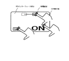
また、ディスプレイ上において、指先とディスプレイの相対的な距離が一定値を下回った(或いは接触した)状態で、図14のように『ON』と指先でなぞることで、ディスプレイ装置の電源を入れるといったように、装置の動作を人体の動作によって制御することもできる。 Further, on the display, when the relative distance between the fingertip and the display is below (or in contact with) a certain value, the display device is turned on by tracing “ON” with the fingertip as shown in FIG. Thus, the operation of the apparatus can be controlled by the movement of the human body.
上記構成においても、物性情報記憶部107を備える場合は次の様にできる。物性情報記憶部107では、筐体や筐体を構成する要素に関する物性の分布情報を予め記憶しており、必要に応じて、指先の位置情報について、補正をかけている。例えば、インターフェース部分102の数箇所に接触させてゼロ点補正することが手段として考えられる。また、筐体に対して、保護フィルタを装着したり、保護シートを貼るなど、インターフェース部分102を取り巻く環境が変化した場合、再度、分布情報を取得し直す機能を有していたり、または、保護フィルタのように頻繁に取り外しする物の場合には、保護フィルタの有無によって分布情報を切り替える機能を有していてもよい。また、操作する物体101の個体差に対しての補正をかける機能を有していてもよい。 Also in the above configuration, when the physical property information storage unit 107 is provided, it can be performed as follows. The physical property information storage unit 107 stores physical property distribution information related to the housing and the elements constituting the housing in advance, and corrects the fingertip position information as necessary. For example, it is conceivable as a means to perform zero point correction by contacting several portions of the interface portion 102. Also, if the environment surrounding the interface part 102 changes, such as attaching a protective filter or attaching a protective sheet to the housing, it has a function to re-acquire distribution information or protect In the case of an object that is frequently removed, such as a filter, it may have a function of switching distribution information depending on the presence or absence of a protective filter. Further, it may have a function of correcting the individual difference of the object 101 to be operated.
101 物体
102 インターフェース部分
103 電磁波検出部
104 位置演算部
105 形状記憶部
106 電磁波
107 物性情報記憶部
201 情報入出力制御部
301、401 集光部
302 変位検出部
101 objects
102 Interface part
103 Electromagnetic wave detector
104 Position calculator
105 Shape memory
106 Electromagnetic waves
107 Physical property information storage
201 Information input / output controller
301, 401 Light collector
302 Displacement detector
Claims (11)
30GHzから30THzの周波数帯域内の電磁波を検出するための検出部と、
前記検出部を格納している筐体と、
前記筐体の外形情報を記憶している記憶部と、
前記筐体に対して前記検出部と反対側に位置する物体から発生し、且つ前記筐体を透過してくる前記電磁波を、前記検出部が検出することにより取得される情報から、該物体と該検出部との相対的な位置情報を演算するための演算部と、を有し、
前記演算部は、演算して取得される前記物体と前記検出部との相対的な位置情報と、前記記憶部が記憶している外形情報とを用いて、前記筐体と前記物体との相対的な位置情報を演算することを特徴とする位置検出装置。 A position detection device for detecting the position of an object,
A detection unit for detecting electromagnetic waves in a frequency band of 30 GHz to 30 THz;
A housing that stores the detection unit,
A storage unit storing external shape information of the housing;
Generated from an object located on the opposite side to the detector unit relative to the housing, a and the electromagnetic wave coming transmitted through the housing, from the information that will be acquired by the detecting unit detects, and said object have a, a calculation unit for calculating the relative position information between the detection unit,
The calculation unit uses the relative position information of the object and the detection unit acquired by calculation and the external shape information stored in the storage unit to determine the relative relationship between the casing and the object. position置検out device you and calculates the position information.
前記演算部は、前記関係に基づいて該伝搬距離を求めることを特徴とする請求項4に記載の位置検出装置。The position detection device according to claim 4, wherein the calculation unit obtains the propagation distance based on the relationship.
前記演算部は、前記分布情報に基づいて前記筐体と前記物体との相対位置を演算することを特徴とする請求項1乃至6のいずれか1項に記載の位置検出装置。The position detection device according to claim 1, wherein the calculation unit calculates a relative position between the housing and the object based on the distribution information.
情報端末装置と、
前記演算部が演算した前記相対位置に基づいて、前記情報端末装置の動作を制御するための制御部と、
を有することを特徴とする情報入力装置。 An information input device including the position detection device according to any one of claims 1 to 9 ,
An information terminal device;
A control unit for controlling the operation of the information terminal device based on the relative position calculated by the calculation unit ;
An information input device comprising:
30GHzから30THzの周波数帯域内の電磁波を検出するための検出部と、A detection unit for detecting electromagnetic waves in a frequency band of 30 GHz to 30 THz;
前記検出部を格納している筐体と、A housing storing the detection unit;
前記筐体の外形情報を記憶している記憶部と、A storage unit storing external shape information of the housing;
前記筐体に対して前記検出部と反対側に位置する物体から発生し、且つ前記筐体を透過してくる前記電磁波を、前記検出部が検出することにより取得される情報から、該物体と該検出部との相対的な位置情報を演算するための演算部と、を有し、From the information generated by the detection unit detecting the electromagnetic wave generated from an object located on the opposite side of the detection unit with respect to the case and transmitted through the case, the object and A calculation unit for calculating positional information relative to the detection unit,
前記検出部が検出することにより取得される情報が、前記筐体に入射する該電磁波の入射角度及び強度であり、Information acquired by detection by the detection unit is an incident angle and intensity of the electromagnetic wave incident on the housing,
前記演算部は、前記入射角度と前記強度とから前記物体と前記検出部との相対的な位置情報を演算し、且つ、演算して取得される前記物体と前記検出部との相対的な位置情報と、前記記憶部が記憶している外形情報とを用いて、前記筐体と該物体との相対的な位置情報を演算することを特徴とする位置検出装置。The calculation unit calculates relative position information between the object and the detection unit from the incident angle and the intensity, and calculates and acquires a relative position between the object and the detection unit. A position detection apparatus that calculates relative position information between the casing and the object using information and external shape information stored in the storage unit.
Priority Applications (3)
| Application Number | Priority Date | Filing Date | Title |
|---|---|---|---|
| JP2003322137A JP4136858B2 (en) | 2003-09-12 | 2003-09-12 | Position detection device and information input device |
| US10/539,268 US7248995B2 (en) | 2003-09-12 | 2004-09-08 | Spatial position detection method, information input method, spatial position detection apparatus, and information input apparatus |
| PCT/JP2004/013394 WO2005026941A1 (en) | 2003-09-12 | 2004-09-08 | Spatial position detection method, information input method, spatial position detection apparatus, and information input apparatus |
Applications Claiming Priority (1)
| Application Number | Priority Date | Filing Date | Title |
|---|---|---|---|
| JP2003322137A JP4136858B2 (en) | 2003-09-12 | 2003-09-12 | Position detection device and information input device |
Publications (3)
| Publication Number | Publication Date |
|---|---|
| JP2005091044A JP2005091044A (en) | 2005-04-07 |
| JP2005091044A5 JP2005091044A5 (en) | 2007-11-15 |
| JP4136858B2 true JP4136858B2 (en) | 2008-08-20 |
Family
ID=34308667
Family Applications (1)
| Application Number | Title | Priority Date | Filing Date |
|---|---|---|---|
| JP2003322137A Expired - Fee Related JP4136858B2 (en) | 2003-09-12 | 2003-09-12 | Position detection device and information input device |
Country Status (3)
| Country | Link |
|---|---|
| US (1) | US7248995B2 (en) |
| JP (1) | JP4136858B2 (en) |
| WO (1) | WO2005026941A1 (en) |
Families Citing this family (64)
| Publication number | Priority date | Publication date | Assignee | Title |
|---|---|---|---|---|
| US7952570B2 (en) | 2002-06-08 | 2011-05-31 | Power2B, Inc. | Computer navigation |
| WO2005001505A1 (en) * | 2003-06-25 | 2005-01-06 | Canon Kabushiki Kaisha | High frequency electrical signal control device and sensing system |
| JP4533044B2 (en) * | 2003-08-27 | 2010-08-25 | キヤノン株式会社 | Sensor |
| JP2005157601A (en) | 2003-11-25 | 2005-06-16 | Canon Inc | Layered object counting device and method using electromagnetic wave |
| JP4217646B2 (en) * | 2004-03-26 | 2009-02-04 | キヤノン株式会社 | Authentication method and authentication apparatus |
| JP4546326B2 (en) * | 2004-07-30 | 2010-09-15 | キヤノン株式会社 | Sensing device |
| JP2006121643A (en) * | 2004-09-21 | 2006-05-11 | Canon Inc | Planar antenna |
| JP4878180B2 (en) * | 2005-03-24 | 2012-02-15 | キヤノン株式会社 | Inspection equipment using electromagnetic waves |
| JP4390147B2 (en) * | 2005-03-28 | 2009-12-24 | キヤノン株式会社 | Variable frequency oscillator |
| JP4250603B2 (en) * | 2005-03-28 | 2009-04-08 | キヤノン株式会社 | Terahertz wave generating element and manufacturing method thereof |
| JP2006275910A (en) * | 2005-03-30 | 2006-10-12 | Canon Inc | System and method for position sensing |
| US10452207B2 (en) * | 2005-05-18 | 2019-10-22 | Power2B, Inc. | Displays and information input devices |
| US8610675B2 (en) | 2007-03-14 | 2013-12-17 | Power2B, Inc. | Interactive devices |
| JP4402026B2 (en) * | 2005-08-30 | 2010-01-20 | キヤノン株式会社 | Sensing device |
| JP4773839B2 (en) * | 2006-02-15 | 2011-09-14 | キヤノン株式会社 | Detection device for detecting information of an object |
| JP4481946B2 (en) | 2006-03-17 | 2010-06-16 | キヤノン株式会社 | Detection element and image forming apparatus |
| JP4732201B2 (en) * | 2006-03-17 | 2011-07-27 | キヤノン株式会社 | Sensing device using electromagnetic waves |
| JP5132146B2 (en) * | 2006-03-17 | 2013-01-30 | キヤノン株式会社 | Analysis method, analyzer, and specimen holding member |
| JP4898472B2 (en) | 2006-04-11 | 2012-03-14 | キヤノン株式会社 | Inspection device |
| JP4829669B2 (en) * | 2006-04-28 | 2011-12-07 | キヤノン株式会社 | Sample information acquisition apparatus and sample information acquisition method |
| JP4709059B2 (en) * | 2006-04-28 | 2011-06-22 | キヤノン株式会社 | Inspection apparatus and inspection method |
| JP5006642B2 (en) | 2006-05-31 | 2012-08-22 | キヤノン株式会社 | Terahertz wave oscillator |
| JP5196750B2 (en) | 2006-08-25 | 2013-05-15 | キヤノン株式会社 | Oscillating element |
| JP4873746B2 (en) * | 2006-12-21 | 2012-02-08 | キヤノン株式会社 | Oscillating element |
| JP4977048B2 (en) * | 2007-02-01 | 2012-07-18 | キヤノン株式会社 | Antenna element |
| US8067739B2 (en) * | 2007-06-22 | 2011-11-29 | Canon Kabushiki Kaisha | Photoconductive element for generation and detection of terahertz wave |
| JP5354971B2 (en) * | 2007-08-31 | 2013-11-27 | キヤノン株式会社 | Imaging method and apparatus |
| US7869036B2 (en) * | 2007-08-31 | 2011-01-11 | Canon Kabushiki Kaisha | Analysis apparatus for analyzing a specimen by obtaining electromagnetic spectrum information |
| JP5144175B2 (en) * | 2007-08-31 | 2013-02-13 | キヤノン株式会社 | Inspection apparatus and inspection method using electromagnetic waves |
| JP4807707B2 (en) * | 2007-11-30 | 2011-11-02 | キヤノン株式会社 | Waveform information acquisition device |
| JP4975000B2 (en) * | 2007-12-07 | 2012-07-11 | キヤノン株式会社 | Electromagnetic wave generating element, electromagnetic wave integrated element, and electromagnetic wave detecting device |
| JP4975001B2 (en) * | 2007-12-28 | 2012-07-11 | キヤノン株式会社 | Waveform information acquisition apparatus and waveform information acquisition method |
| JP5341488B2 (en) | 2008-01-18 | 2013-11-13 | キヤノン株式会社 | Apparatus and method for measuring terahertz waves |
| JP5328319B2 (en) * | 2008-01-29 | 2013-10-30 | キヤノン株式会社 | Inspection apparatus and inspection method using terahertz waves |
| ITMO20080087A1 (en) * | 2008-03-27 | 2009-09-28 | Daniele Zetti | RELEASED HINGE PERFORMED FOR THE SUPPORT OF A CLOSING ELEMENT |
| TWM356029U (en) * | 2008-12-05 | 2009-05-01 | Ome Technology Co Ltd | Pre-tightening structure for liner sliding rail |
| JP5665305B2 (en) * | 2008-12-25 | 2015-02-04 | キヤノン株式会社 | Analysis equipment |
| US20100228488A1 (en) * | 2009-03-05 | 2010-09-09 | Searete Llc, A Limited Liability Corporation Of The State Of Delaware | Postural information system and method |
| US20100228153A1 (en) * | 2009-03-05 | 2010-09-09 | Searete Llc, A Limited Liability Corporation Of The State Of Delaware | Postural information system and method |
| US20100228493A1 (en) * | 2009-03-05 | 2010-09-09 | Searete Llc, A Limited Liability Corporation Of The State Of Delaware | Postural information system and method including direction generation based on collection of subject advisory information |
| US20100228490A1 (en) * | 2009-03-05 | 2010-09-09 | Searete Llc, A Limited Liability Corporation Of The State Of Delaware | Postural information system and method |
| US20100225473A1 (en) * | 2009-03-05 | 2010-09-09 | Searete Llc, A Limited Liability Corporation Of The State Of Delaware | Postural information system and method |
| US20100228494A1 (en) * | 2009-03-05 | 2010-09-09 | Searete Llc, A Limited Liability Corporation Of The State Of Delaware | Postural information system and method including determining subject advisory information based on prior determined subject advisory information |
| US20100225491A1 (en) * | 2009-03-05 | 2010-09-09 | Searete Llc, A Limited Liability Corporation Of The State Of Delaware | Postural information system and method |
| US20100271200A1 (en) * | 2009-03-05 | 2010-10-28 | Searete Llc, A Limited Liability Corporation Of The State Of Delaware | Postural information system and method including determining response to subject advisory information |
| US20100225474A1 (en) * | 2009-03-05 | 2010-09-09 | Searete Llc, A Limited Liability Corporation Of The State Of Delaware | Postural information system and method |
| US20100225490A1 (en) * | 2009-03-05 | 2010-09-09 | Leuthardt Eric C | Postural information system and method including central determining of subject advisory information based on subject status information and postural influencer status information |
| US20100228154A1 (en) * | 2009-03-05 | 2010-09-09 | Searete Llc, A Limited Liability Corporation Of The State Of Delaware | Postural information system and method including determining response to subject advisory information |
| US20100225498A1 (en) * | 2009-03-05 | 2010-09-09 | Searete Llc, A Limited Liability Corporation | Postural information system and method |
| US20100228487A1 (en) * | 2009-03-05 | 2010-09-09 | Searete Llc, A Limited Liability Corporation Of The State Of Delaware | Postural information system and method |
| US9024976B2 (en) * | 2009-03-05 | 2015-05-05 | The Invention Science Fund I, Llc | Postural information system and method |
| US20100228159A1 (en) * | 2009-03-05 | 2010-09-09 | Searete Llc, A Limited Liability Corporation Of The State Of Delaware | Postural information system and method |
| US20100228495A1 (en) * | 2009-03-05 | 2010-09-09 | Searete Llc, A Limited Liability Corporation Of The State Of Delaware | Postural information system and method including determining subject advisory information based on prior determined subject advisory information |
| JP5632599B2 (en) | 2009-09-07 | 2014-11-26 | キヤノン株式会社 | Oscillator |
| JP5612842B2 (en) | 2009-09-07 | 2014-10-22 | キヤノン株式会社 | Oscillator |
| US8519856B2 (en) | 2010-06-18 | 2013-08-27 | The Invention Science Fund I, Llc | Mapping system for irradiation protection |
| US8462002B2 (en) | 2010-06-18 | 2013-06-11 | The Invention Science Fund I, Llc | Personal telecommunication device with target-based exposure control |
| US8463288B2 (en) | 2010-06-18 | 2013-06-11 | The Invention Science Fund I, Llc | Irradiation self-protection from user telecommunication device |
| US8686865B2 (en) | 2010-06-18 | 2014-04-01 | The Invention Science Fund I, Llc | Interactive technique to reduce irradiation from external source |
| CN102129324B (en) * | 2011-03-17 | 2012-05-02 | 汉王科技股份有限公司 | Touch control device, control method thereof and electronic equipment with touch control device |
| WO2013024620A1 (en) * | 2011-08-15 | 2013-02-21 | 日本電気株式会社 | Information processing terminal, layout adjustment method, and program |
| CN105120089B (en) * | 2015-08-17 | 2020-01-03 | 惠州Tcl移动通信有限公司 | Method for mobile terminal to automatically answer call and mobile terminal |
| US10152802B2 (en) * | 2016-03-31 | 2018-12-11 | Radiant Geospatial Solutions Llc | Method and apparatus for imaging the silhouette of an object occluding a light source using a synthetic aperature |
| JP7362409B2 (en) | 2019-10-17 | 2023-10-17 | キヤノン株式会社 | Lighting equipment and camera systems |
Family Cites Families (20)
| Publication number | Priority date | Publication date | Assignee | Title |
|---|---|---|---|---|
| SE462999B (en) * | 1987-05-29 | 1990-09-24 | Saab Missiles Ab | DEVICE MAKES SELECTIVE DETECTION OF GOODS |
| JPH06168065A (en) | 1992-10-02 | 1994-06-14 | Sony Corp | Device and method for optical position detectioin |
| JPH0735842A (en) | 1993-07-20 | 1995-02-07 | Matsushita Electric Ind Co Ltd | Three-dimensional position detector |
| JP3210159B2 (en) | 1993-12-10 | 2001-09-17 | キヤノン株式会社 | Semiconductor laser, light source device, optical communication system and optical communication method |
| JPH07307530A (en) | 1994-03-17 | 1995-11-21 | Canon Inc | Polarizable and modulatable semiconductor laser |
| US5659560A (en) | 1994-05-12 | 1997-08-19 | Canon Kabushiki Kaisha | Apparatus and method for driving oscillation polarization selective light source, and optical communication system using the same |
| JP3254928B2 (en) | 1994-09-12 | 2002-02-12 | 日産自動車株式会社 | Radar position detection sensor and radar using the same |
| US5764670A (en) | 1995-02-27 | 1998-06-09 | Canon Kabushiki Kaisha | Semiconductor laser apparatus requiring no external modulator, method of driving semiconductor laser device, and optical communication system using the semiconductor laser apparatus |
| AU4027997A (en) | 1996-09-06 | 1998-03-26 | Lifetech Corporation | Method and apparatus for the sterilization of biological substrates |
| JP3794180B2 (en) * | 1997-11-11 | 2006-07-05 | セイコーエプソン株式会社 | Coordinate input system and coordinate input device |
| JP2001042170A (en) | 1999-07-28 | 2001-02-16 | Canon Inc | Optical wiring device, its driving method and electronic apparatus using the device |
| WO2001069173A1 (en) * | 2000-03-10 | 2001-09-20 | Spectra Precision Inc. | Versatile transmitter and receiver for position measurement |
| WO2005001505A1 (en) | 2003-06-25 | 2005-01-06 | Canon Kabushiki Kaisha | High frequency electrical signal control device and sensing system |
| JP4533044B2 (en) | 2003-08-27 | 2010-08-25 | キヤノン株式会社 | Sensor |
| JP2005157601A (en) | 2003-11-25 | 2005-06-16 | Canon Inc | Layered object counting device and method using electromagnetic wave |
| JP4217646B2 (en) | 2004-03-26 | 2009-02-04 | キヤノン株式会社 | Authentication method and authentication apparatus |
| JP4250573B2 (en) | 2004-07-16 | 2009-04-08 | キヤノン株式会社 | element |
| JP4546326B2 (en) | 2004-07-30 | 2010-09-15 | キヤノン株式会社 | Sensing device |
| JP4250603B2 (en) | 2005-03-28 | 2009-04-08 | キヤノン株式会社 | Terahertz wave generating element and manufacturing method thereof |
| JP2006275910A (en) | 2005-03-30 | 2006-10-12 | Canon Inc | System and method for position sensing |
-
2003
- 2003-09-12 JP JP2003322137A patent/JP4136858B2/en not_active Expired - Fee Related
-
2004
- 2004-09-08 US US10/539,268 patent/US7248995B2/en not_active Expired - Fee Related
- 2004-09-08 WO PCT/JP2004/013394 patent/WO2005026941A1/en active Application Filing
Also Published As
| Publication number | Publication date |
|---|---|
| JP2005091044A (en) | 2005-04-07 |
| WO2005026941A1 (en) | 2005-03-24 |
| US20060085159A1 (en) | 2006-04-20 |
| US7248995B2 (en) | 2007-07-24 |
Similar Documents
| Publication | Publication Date | Title |
|---|---|---|
| JP4136858B2 (en) | Position detection device and information input device | |
| US5686942A (en) | Remote computer input system which detects point source on operator | |
| US11809623B2 (en) | Head-mounted display device and operating method of the same | |
| US20020061217A1 (en) | Electronic input device | |
| TW201635092A (en) | Display device, electronic device, hand-wearing device and control system | |
| US9372572B2 (en) | Touch locating method and optical touch system | |
| JP2013125247A (en) | Head-mounted display and information display apparatus | |
| US11852318B2 (en) | Optical system for noise mitigation | |
| JP2005520239A (en) | Touchpad, stylus using touchpad, and method of operating touchpad | |
| US10261327B2 (en) | Head mounted display and control method for head mounted display | |
| GB2472767A (en) | Optical computer input with single frustrated total internal reflection mousing surface | |
| US20130027548A1 (en) | Depth perception device and system | |
| KR20110138975A (en) | Apparatus for detecting coordinates, display device, security device and electronic blackboard including the same | |
| CN114859367A (en) | Optical interferometric proximity sensor with optical path extender | |
| JP5863780B2 (en) | Apparatus for virtual input device for mobile computing device and method in the apparatus | |
| JP4758667B2 (en) | Pointer remote control device | |
| CN113661433B (en) | Head-mounted display device and operation method thereof | |
| JPH08297536A (en) | Head mount type display unit | |
| JP4526362B2 (en) | Input device | |
| WO2014076992A1 (en) | Interface device, display system, and input reception method | |
| JP7371382B2 (en) | Position pointing device, display system, position pointing method, and program | |
| JP2002244808A (en) | Coordinate input device and method of controlling the same, computer-readable memory, and program | |
| TW201421328A (en) | Multi-touch optical input device and method thereof |
Legal Events
| Date | Code | Title | Description |
|---|---|---|---|
| A621 | Written request for application examination |
Free format text: JAPANESE INTERMEDIATE CODE: A621 Effective date: 20051121 |
|
| A521 | Request for written amendment filed |
Free format text: JAPANESE INTERMEDIATE CODE: A523 Effective date: 20070928 |
|
| A131 | Notification of reasons for refusal |
Free format text: JAPANESE INTERMEDIATE CODE: A131 Effective date: 20080131 |
|
| A521 | Request for written amendment filed |
Free format text: JAPANESE INTERMEDIATE CODE: A523 Effective date: 20080331 |
|
| TRDD | Decision of grant or rejection written | ||
| A01 | Written decision to grant a patent or to grant a registration (utility model) |
Free format text: JAPANESE INTERMEDIATE CODE: A01 Effective date: 20080521 |
|
| A01 | Written decision to grant a patent or to grant a registration (utility model) |
Free format text: JAPANESE INTERMEDIATE CODE: A01 |
|
| A61 | First payment of annual fees (during grant procedure) |
Free format text: JAPANESE INTERMEDIATE CODE: A61 Effective date: 20080603 |
|
| R150 | Certificate of patent or registration of utility model |
Free format text: JAPANESE INTERMEDIATE CODE: R150 |
|
| FPAY | Renewal fee payment (event date is renewal date of database) |
Free format text: PAYMENT UNTIL: 20110613 Year of fee payment: 3 |
|
| FPAY | Renewal fee payment (event date is renewal date of database) |
Free format text: PAYMENT UNTIL: 20120613 Year of fee payment: 4 |
|
| FPAY | Renewal fee payment (event date is renewal date of database) |
Free format text: PAYMENT UNTIL: 20120613 Year of fee payment: 4 |
|
| FPAY | Renewal fee payment (event date is renewal date of database) |
Free format text: PAYMENT UNTIL: 20130613 Year of fee payment: 5 |
|
| LAPS | Cancellation because of no payment of annual fees |