JP4773839B2 - Detection device for detecting information of an object - Google Patents
Detection device for detecting information of an object Download PDFInfo
- Publication number
- JP4773839B2 JP4773839B2 JP2006037765A JP2006037765A JP4773839B2 JP 4773839 B2 JP4773839 B2 JP 4773839B2 JP 2006037765 A JP2006037765 A JP 2006037765A JP 2006037765 A JP2006037765 A JP 2006037765A JP 4773839 B2 JP4773839 B2 JP 4773839B2
- Authority
- JP
- Japan
- Prior art keywords
- electromagnetic wave
- thz
- image
- relative position
- distribution
- Prior art date
- Legal status (The legal status is an assumption and is not a legal conclusion. Google has not performed a legal analysis and makes no representation as to the accuracy of the status listed.)
- Active
Links
Images


Classifications
-
- G—PHYSICS
- G01—MEASURING; TESTING
- G01N—INVESTIGATING OR ANALYSING MATERIALS BY DETERMINING THEIR CHEMICAL OR PHYSICAL PROPERTIES
- G01N22/00—Investigating or analysing materials by the use of microwaves or radio waves, i.e. electromagnetic waves with a wavelength of one millimetre or more
Landscapes
- Physics & Mathematics (AREA)
- Electromagnetism (AREA)
- Health & Medical Sciences (AREA)
- Life Sciences & Earth Sciences (AREA)
- Chemical & Material Sciences (AREA)
- Analytical Chemistry (AREA)
- Biochemistry (AREA)
- General Health & Medical Sciences (AREA)
- General Physics & Mathematics (AREA)
- Immunology (AREA)
- Pathology (AREA)
- Investigating Or Analysing Materials By Optical Means (AREA)
Description
本発明は、主にミリ波からテラヘルツ波領域(30GHz〜30THz)の高周波電磁波を用いて物体の性状や形状を観察する画像取得装置などの対象物(検体)の情報を検出するための検出装置、及びその検出方法に関する。 The present invention mainly relates to a detection device for detecting information on an object (specimen) such as an image acquisition device for observing the properties and shape of an object using high-frequency electromagnetic waves in the millimeter wave to terahertz wave region (30 GHz to 30 THz). And a detection method thereof.
近年、ミリ波からテラヘルツ(THz)波にかけた電磁波(30GHz〜30THz;以後単にTHz、THz波、THz光などという)を用いた非破壊なセンシング技術が開発されてきている。この周波数帯の電磁波の応用分野として、X線に代わる安全な透視検査装置としてイメージングを行う技術が開発されている。また、物質内部の吸収スペクトルや複素誘電率を求めて結合状態などの物性を調べる分光技術、生体分子の解析技術、キャリア濃度や移動度を評価する技術なども開発されている。 In recent years, non-destructive sensing technology using electromagnetic waves (30 GHz to 30 THz; hereinafter simply referred to as THz, THz waves, THz light, etc.) applied from millimeter waves to terahertz (THz) waves has been developed. As an application field of electromagnetic waves in this frequency band, imaging technology has been developed as a safe fluoroscopic inspection apparatus replacing X-rays. In addition, a spectroscopic technique for obtaining an absorption spectrum and a complex dielectric constant inside a substance and examining physical properties such as a binding state, a biomolecule analysis technique, and a technique for evaluating carrier concentration and mobility have been developed.
従来、THz発生手段の一例として、基板上に成膜した光伝導膜に、電極を兼ねたアンテナを備えた光伝導スイッチ素子が好適に用いられている(特許文献1参照)。光伝導膜としては、放射線処理したシリコン膜がサファイア基板上に成膜されたものや、GaAs基板に低温で成長したLT-GaAsが用いられることが多い。 Conventionally, as an example of THz generating means, a photoconductive switch element having an antenna that also serves as an electrode for a photoconductive film formed on a substrate is suitably used (see Patent Document 1). As the photoconductive film, a radiation-treated silicon film formed on a sapphire substrate or LT-GaAs grown on a GaAs substrate at low temperature is often used.
この光伝導スイッチ素子を発生側、検出側の両方に配置して、物体を2次元的にスキャンしてTHz画像を得る図9に示す方法が提案されている(特許文献2参照)。特許文献2には、THz波の物体に対する分散、吸収特性を利用して、光学的には観察できない内部の画像、例えば、ICチップ内の配線パターンなどが取得できることが示されている。
A method shown in FIG. 9 is proposed in which the photoconductive switch elements are arranged on both the generation side and the detection side, and an object is two-dimensionally scanned to obtain a THz image (see Patent Document 2).
このスキャン方法では2次元画像を得るのに時間を要するため、THz波を1次元状領域で一括して物体に照射して高速に検査する方法も提案されている(特許文献3参照)。特許文献3には、THzパルス光(パルス幅が概ね3psec以下)を放物柱面鏡などによって1次元状のビームに成形して、物体の透過、反射分光を高速に行うことが示されている。
しかしながら、特許文献2や特許文献3に開示されている方法では、フェムト秒レーザを用いたTHzパルス波の励起(ポンプ)とプローブ側レーザによるゲート動作を伴う検出を行っている。したがって、ポンプとプローブの同期をとる必要があるために、光学系が複雑で自由度が少ないものとなっている。また、一般に光伝導スイッチ素子から発生するTHz波のパワーはμWオーダーに満たないものであるため、S/N比を大きく取ることが難しい。そのため、感度向上のために信号取得スピードを遅くする必要があり、画像取得スピードには限界がある。更に、パルス光を用いているため、波長分散の影響を受けやすく解像度に限界がある。また、ハイパワーフェムト秒レーザなど、消費電力が大きい大型で高価な装置が必要になるため、応用範囲が限られており、THzイメージングが産業的に普及する上での障害になっていた。
However, in the methods disclosed in
また、従来の画像取得では、出射されたTHz波の強度分布として円形または楕円でガウス分布を持つものを利用することが多かった。THz発生装置によってはガウス分布にもならず多峰性の分布を持つものもあった。そのため、複数画素を一括して取得する場合に強度分布があるために、周辺の画質が劣化しがちであった。 In conventional image acquisition, the intensity distribution of the emitted THz wave is often circular or elliptical and has a Gaussian distribution. Some THz generators have a multimodal distribution as well as a Gaussian distribution. For this reason, when acquiring a plurality of pixels at once, there is an intensity distribution, so that the peripheral image quality tends to deteriorate.
上記課題に鑑み、対象物の情報を検出するための本発明の検出装置は、照射手段とアレイ型検出手段と情報取得手段を有する。照射手段は、以上30THz以下の周波数領域の少なくとも一部の周波数成分を含み、且つ振幅変化が10−11秒以上の時間でしか起こらないか若しくは振幅が時間的に一定である電磁波を矩形状ビームとして対象物に照射する。アレイ型検出手段は、対象物と電磁波が相互作用することで対象物を透過若しくは反射した電磁波を複数の画素で検出する。情報取得手段は、前記アレイ型検出手段で検出した電磁波の情報を用いて、対象物の情報を取得する。更に、前記情報取得手段は、前記対象物に照射される矩形状ビームと前記対象物との相対位置を、該矩形状ビームを移動することで、変化させる相対位置変化手段と、前記相対位置変化手段により前記相対位置を変化させながら、逐次、前記アレイ型検出手段で検出した電磁波の情報を用いて前記矩形状ビームの空間強度分布に対応した画像を合成し、前記相対位置の変化領域に対応する前記対象物の画像を取得する画像取得手段と、を含み、前記アレイ型検出手段は、前記複数の画素の一部を使って、前記矩形状ビームの空間強度分布を検出する。 In view of the above problems, a detection apparatus of the present invention for detecting information on an object includes an irradiation unit, an array type detection unit, and an information acquisition unit. The irradiating means includes a rectangular beam of electromagnetic waves that include at least a part of frequency components in a frequency region of 30 THz or less and whose amplitude changes only in a time of 10 −11 seconds or more or whose amplitude is constant over time. As shown in FIG. The array-type detection unit detects an electromagnetic wave that has been transmitted or reflected through the object by the interaction between the object and the electromagnetic wave using a plurality of pixels. The information acquisition means acquires information on the object using information on the electromagnetic waves detected by the array type detection means. Furthermore, the information acquisition means includes a relative position changing means for changing a relative position between the rectangular beam irradiated to the object and the object by moving the rectangular beam, and the relative position change. while changing the relative position by means sequentially, using an electromagnetic wave information detected by the array type detection means synthesizes an image corresponding to the spatial intensity distribution of the rectangular beam, corresponding to the change area of the relative positions look including the an image acquisition means for acquiring an image of the object to the array type detecting means, with a portion of said plurality of pixels, to detect the spatial intensity distribution of the rectangular beam.
また、上記課題に鑑み、対象物の情報を検出するための本発明の検出方法は、照射ステップ段と検出ステップと情報取得ステップを含む。照射ステップでは、30GHz以上30THz以下の周波数領域の少なくとも一部の周波数成分を含み、且つ振幅変化が10−11秒以上の時間でしか起こらないか若しくは振幅が時間的に一定である電磁波を矩形状ビームとして対象物に照射する。検出ステップでは、対象物と電磁波が相互作用することで対象物を透過若しくは反射した電磁波を検出する。情報取得ステップでは、前記検出ステップで検出した電磁波の情報を用いて、前記対象物の情報を取得する。
Moreover, in view of the said subject, the detection method of this invention for detecting the information of a target object includes an irradiation step step, a detection step, and an information acquisition step. The irradiation step, comprise at least a portion of the frequency components below a frequency domain above 30
上記構成において、本発明における矩形状ビームとは、発生手段から発生する円形のガウス分布ビームなどではない、2軸(典型的には長軸と短軸であるが、両軸が等しい場合も含む)を持つビームパターンのビームの総称として定義する。すなわち、図8(a)に示す様な一般的な長方形、図8(b)に示す様な細長い短冊形状、図8(c)に示す様な扁平の楕円形状などが本発明のビーム形状として含まれる。更には、長方形、正方形などの一般的な矩形状や扁平の楕円形状の他、ひし形、台形、その他各種多角形、曲線を含む形状なども、大雑把に見て2軸を持つ矩形的なパターンであれば、それらも含まれる。例えば、アレイ検出器で一括して電磁波を検出して画像取得する領域を重ね合わせて全体画像を取得する方法が可能であれば、どのような矩形的なビーム形状でもよい。 In the above configuration, the rectangular beam in the present invention is not a circular Gaussian beam generated from the generating means, but includes two axes (typically a major axis and a minor axis, but includes both axes being equal. ) Is defined as a general term for beams having a beam pattern. That is, a general rectangular shape as shown in FIG. 8 (a), an elongated strip shape as shown in FIG. 8 (b), a flat elliptical shape as shown in FIG. included. Furthermore, in addition to general rectangular shapes such as rectangles and squares and flat elliptical shapes, rhombuses, trapezoids, other polygons, shapes including curves, etc. are roughly rectangular patterns with two axes. If there are, they are also included. For example, any rectangular beam shape may be used as long as a method of acquiring an entire image by superimposing regions for acquiring images by collectively detecting electromagnetic waves with an array detector is possible.
本発明によれば、上記の如き電磁波を矩形状ビームとして対象物に照射するので、対象物の情報(透過画像、反射画像など)を精度(画像の解像度など)を損なわないで、比較的高速に取得することができる。 According to the present invention, since the electromagnetic wave as described above is irradiated onto the object as a rectangular beam, the information (transmission image, reflection image, etc.) of the object is relatively high speed without losing accuracy (image resolution, etc.). Can be obtained.
本発明の実施形態を以下に説明する。本発明の一実施形態においては、フェムト秒レーザ励起のTHz発生装置でなく、比較的出力の高い(μWオーダー以上)コヒーレントTHz発生器(発生手段)からのTHz出力を変換手段により矩形の形状に変換して対象物(検体)に照射する。そして、矩形状ビームのTHz波と検体の相対位置を相対位置変化手段でスキャンしながら、検出手段であるアレイ型電磁波検出器で検体からのTHz波を検出し、検出したTHz波の情報を用いて情報取得手段で検体の所望の領域の画像を得る。こうして、矩形状ビームに対応するアレイ検出器を用いて、その矩形状ビームによって複数の画素を取得し、周知の技術を用いた情報取得手段で複数画素の領域を複数重ね合わせて検体の1つの画像を取得する。 Embodiments of the present invention will be described below. In one embodiment of the present invention, a THz output from a coherent THz generator (generation unit) having a relatively high output (μW order or more) is not a femtosecond laser-excited THz generator, but is converted into a rectangular shape by a conversion unit. Convert and irradiate the object (specimen). Then, while scanning the relative position of the rectangular beam THz wave and the specimen with the relative position changing means, the array type electromagnetic wave detector as the detecting means detects the THz wave from the specimen, and uses the detected THz wave information. Then, an image of a desired region of the specimen is obtained by the information acquisition means. In this way, using the array detector corresponding to the rectangular beam, a plurality of pixels are acquired by the rectangular beam, and a plurality of pixel areas are overlapped by an information acquisition unit using a known technique to obtain one sample. Get an image.
THz発生器としては、量子カスケード型もしくは共鳴トンネルダイオードなどの半導体発振器、後進行波管(BWO)、ガンダイオード及びその高調波発生器、LNなどの非線形結晶を用いたパラメトリック発振器などのコヒーレントTHz光源が好適に用いられる。典型的な出力パワーは数μW〜数100mWである。或いは、ヒーターや白熱球、水銀ランプなどでフィルタによりTHz領域の電磁波を取り出したインコヒーレント光源でもよい。これらは、フェムト秒レーザ励起のTHz発生源と比較して、出力パワーの変動がCW動作で殆どないかミリ秒からナノ秒程度の変動しかなく、10psec未満の速さでの時間変動がないということで区別される。 THz generators include coherent THz light sources such as semiconductor oscillators such as quantum cascade or resonant tunneling diodes, back-traveling wave tubes (BWO), Gunn diodes and their harmonic generators, and parametric oscillators using nonlinear crystals such as LN Are preferably used. Typical output power is several μW to several hundred mW. Alternatively, an incoherent light source in which electromagnetic waves in the THz region are extracted by a filter with a heater, an incandescent bulb, a mercury lamp, or the like may be used. Compared with the THz source of femtosecond laser excitation, there is almost no fluctuation of output power in CW operation or only fluctuation of millisecond to nanosecond, and there is no time fluctuation at a speed of less than 10 psec. It is distinguished by that.
一方、検出器としては、強誘電性結晶による焦電検出器、MEMS型熱検出器、ショットキーダイオード、共鳴トンネルダイオード、半導体量子検出器などをアレイ化したものを用いることができる。THz発生器から出力された電磁波は、レンズや放物面鏡などでビーム制御されたのち、シリンドリカルレンズまたは放物柱面鏡などを用いて矩形状ビームに変換される。このとき、拡散板などを用いてビーム内の強度分布をガウス分布状から矩形分布状に変換すると、画像取得手段で得られる画像にムラが起きない様にすることができる。 On the other hand, as the detector, a pyroelectric detector using a ferroelectric crystal, a MEMS thermal detector, a Schottky diode, a resonant tunnel diode, a semiconductor quantum detector, or the like can be used. The electromagnetic wave output from the THz generator is subjected to beam control using a lens, a parabolic mirror, or the like, and then converted into a rectangular beam using a cylindrical lens or a parabolic column mirror. At this time, if the intensity distribution in the beam is converted from a Gaussian distribution to a rectangular distribution using a diffusing plate or the like, it is possible to prevent unevenness in the image obtained by the image acquisition means.
矩形状の具体的パターンは、発生器と検出器及び検体で決まるS/N比により選択する。すなわち、S/Nが十分確保される場合には長方形または正方形にして、検出器も2次元アレイのものを選択し、2次元画像領域を複数重ねることで全領域の画像を得る。一方、S/N比が十分でない場合には、短冊状或いは1次元線状の扁平の楕円ビームにしてTHz波のパワー密度を向上させ、1次元の画像を複数重ね合わせることで全領域の画像を得ることができる。 The rectangular specific pattern is selected according to the S / N ratio determined by the generator, the detector, and the specimen. In other words, when a sufficient S / N is secured, a rectangular or square shape is selected, and a detector of a two-dimensional array is selected, and an image of the entire region is obtained by overlapping a plurality of two-dimensional image regions. On the other hand, if the S / N ratio is not sufficient, the power density of the THz wave is improved by using a strip-shaped or one-dimensional linear oblong beam, and multiple one-dimensional images are overlaid. Can be obtained.
本実施形態の方法の場合には、ポンプ光とプローブ光の同期をとる必要がないため、光学系の調整が容易になり、全体としても小型化することができる。ただし、検体内の材料分布などの情報を位相情報として取り込む場合には、検出器の前段に遅延系や干渉系(後述の実施例3、4参照)などを設けてもよい。画像は、検体からの透過波、反射波のいずれかまたは両方を用いて取得してもよい。また、相対位置をスキャンする相対位置変化手段としては、ガルバノミラー等を用いて光軸をスキャンする方式、検体を走査ステージやベルトコンベア等で動かす方式などがある。これらの相対位置変化手段は、照射手段において電磁波の反射方向を変化させる可動ミラーを含む手段、また、対象物を1軸方向に移動させて照射電磁波と対象物の相対位置を変化させる手段である。その移動方向については、THz波ビームパターンの長軸に対して交差する方向、望ましくは長軸に対して略垂直方向に行うことが効率的である。 In the case of the method of the present embodiment, it is not necessary to synchronize the pump light and the probe light, so that the adjustment of the optical system is facilitated and the overall size can be reduced. However, when information such as material distribution in the specimen is taken in as phase information, a delay system, an interference system (see Examples 3 and 4 to be described later) or the like may be provided before the detector. The image may be acquired using either or both of a transmitted wave and a reflected wave from the specimen. Further, as relative position changing means for scanning the relative position, there are a method of scanning an optical axis using a galvanometer mirror or the like, a method of moving a specimen by a scanning stage, a belt conveyor or the like. These relative position changing means are means including a movable mirror for changing the reflection direction of the electromagnetic wave in the irradiation means, and means for changing the relative position of the irradiation electromagnetic wave and the target object by moving the target object in one axial direction. . As for the moving direction, it is efficient to perform the movement in a direction crossing the long axis of the THz wave beam pattern, preferably in a direction substantially perpendicular to the long axis.
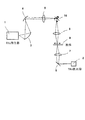
図1及び図2を参照して本実施形態を更に説明する。図1において、1はTHz発生器であり、ここでは、液体窒素温度に冷却することで電流注入により2.9THzで10mWの連続波を出力する量子カスケードレーザである。この出力は、2つの放物面鏡3、4で3cmφ程度の平行ビームに変換される。このビームは、シリンドリカルレンズ5により、紙面に垂直な方向は平行ビームのままで、紙面に平行な成分のみ図1の様に集光ビームとされる。そして、ガルバノミラー10で反射され、もう1度シリンドリカルレンズ6で検体9の表面に絞られて照射される。このとき、紙面に垂直な方向に奥行き3cm程度の短冊状ビームとなっている。
This embodiment will be further described with reference to FIGS. In FIG. 1, 1 is a THz generator, which is a quantum cascade laser that outputs a continuous wave of 10 mW at 2.9 THz by current injection by cooling to liquid nitrogen temperature. This output is converted into a parallel beam of about 3 cmφ by the two parabolic mirrors 3 and 4. This beam is converted into a focused beam by the
検体9を透過後のTHz波は、シリンドリカルレンズ7で再びフォーカスされて、1次元アレイのTHz検出器2で検出される。実際の検出器としては、2次元アレイ状に作製された焦電検出器の一部を使い、ガルバノミラー10の動きと同期して信号検出することで2次元画像を得ることができる。このとき、レンズ6、7は、図1に示す様に、これらの焦点位置に夫々ガルバノミラー面、検体6、検出面が配置される様にすればよい。また、2次元アレイ状に作製された焦電検出器の検出面上で、フォーカスされたTHz波の位置は固定となっていてもよいし、ガルバノミラー10の動きにつれて動いてもよい。
The THz wave after passing through the
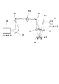
この短冊状ビーム内でTHz強度を一定にするために、図2の様な光学系を用いてもよい。ここでは、放物面鏡4で3cmφの平行ビームとなったTHz波20は、縦方向、横方向のフライアイレンズ21、22を通過することでビーム内強度がガウス分布から矩形分布へと変換される。その後、シリンドリカル凸レンズ23、24で幅1mm、長さ2.5cmの短冊状ビームに変換される。そして、ガルバノミラー25で反射された後、再びシリンドリカル凸レンズ26で検体表面にこのビーム形状27で投影される。この光学系ではレンズ系を用いたが、既に述べた様に反射ミラー系として、シリンドリカルレンズの代わりに放物柱面鏡を用いたり、フライアイレンズの代わりに拡散板などを用いても同様な系を構築できる。
In order to make the THz intensity constant in the strip beam, an optical system as shown in FIG. 2 may be used. Here, the
このときの縦横比の決定については、既に述べた様に、発生器と検出器及び検体で決まるS/N比により選択される。例えば、空間的な強度分布が均一な平行円形ビームとした場合に、アレイTHz検出器でS/Nが2以上確保できるサイズが8mmφであるとする。ここで、イメージングの空間分解能を0.3mmと設定すれば、余裕を持たせて、幅1mmの短冊状ビームにおけるTHzパワーの総量がビーム変形してもほぼ同一となる様に、ビームの長軸方向の長さを決定すればよい。短冊状にしたときにもほぼ均一分布と仮定すると、長軸方向の長さはπ(8/2)2/1=50mmとなる。したがって、1mm×50mmの短冊状ビームで検出が可能と考えられる。ただ、実際にはビーム変換時の損失や周辺部の歪みも考慮して、上記では有効幅(長軸方向の長さ)を25mmとした。検体上における25mm幅(長軸方向の長さ)の短冊状THz波は均一な強度で照射されるため、ムラのない画像を得ることができる。このとき長軸方向のみ矩形分布にして、線の幅方向(短軸方向)にはガウス分布のままでもよい。この場合は、このことを予め記憶しておいて、画像取得手段で補正をかけて画像を形成すればよい。また、アレイ検出器の感光部の幅と短冊状ビームの長軸方向の長さが異なる場合には、適宜シンリンドリカルレンズ等(不図示)を用いて長軸方向にビームを縮小させてもよい。 The aspect ratio at this time is determined by the S / N ratio determined by the generator, the detector, and the specimen as described above. For example, when a parallel circular beam having a uniform spatial intensity distribution is used, it is assumed that the size capable of securing an S / N of 2 or more with an array THz detector is 8 mmφ. Here, if the spatial resolution of imaging is set to 0.3 mm, the long axis direction of the beam is set so that the total amount of THz power in a 1 mm wide strip-shaped beam is almost the same even if the beam is deformed, with a margin. What is necessary is just to determine the length of. Assuming substantially uniform distribution even when the strip, the length of the long axis direction is π (8/2) 2/1 = 50mm. Therefore, it is considered possible to detect with a 1 mm × 50 mm strip beam. However, in practice, the effective width (length in the major axis direction) is set to 25 mm in consideration of the loss during beam conversion and distortion at the periphery. Since a strip-shaped THz wave having a width of 25 mm (length in the major axis direction) on the specimen is irradiated with a uniform intensity, a uniform image can be obtained. At this time, a rectangular distribution may be used only in the long axis direction, and a Gaussian distribution may be maintained in the line width direction (short axis direction). In this case, this may be stored in advance and the image may be corrected by the image acquisition means to form an image. If the width of the photosensitive portion of the array detector is different from the length of the strip beam in the long axis direction, the beam may be appropriately reduced in the long axis direction using a cylindrical lens (not shown). Good.
以上の縦横比については、THz波の強度を強くしたり、THz検出器の感度を高くしたりして更に大きく(すなわち扁平率を高く)し、イメージングの幅を広げることができるが、この様な装置を用いることは装置全体を高価にする。そこで、イメージングの速度とシステムの価格がトレードオフの関係になり、応用する形態の仕様により最適に設計する必要がある。 The above aspect ratio can be further increased by increasing the intensity of the THz wave or increasing the sensitivity of the THz detector (ie, increasing the flatness ratio) to widen the imaging range. Using a simple device makes the entire device expensive. Therefore, there is a trade-off relationship between imaging speed and system price, and it is necessary to design optimally according to the specifications of the application form.
以上のことを踏まえて、図2の構成において、ガルバノミラー25でビーム27の検体上の投影位置を矢印方向に5cmスキャンすれば、2.5cm×5cmの2次元THz画像を得ることができる。更に画像エリアを広げる方法や、対象物からの電磁波の位相変化の情報をも取得して物性の分布をイメージングする方法などについては後述の実施例にて説明する。
Based on the above, in the configuration of FIG. 2, if the projection position of the
以上に述べた本実施形態により、THz波を用いた物体の透過画像または反射画像を解像度高く、高速に取得することができ、装置全体の構成も比較的単純で小型化できる。これにより、THzイメージング装置の適用範囲が広がり、工業製品として空港、各種交通機関、物流などにおける物品検査や、生産現場における良品/欠陥検査、医療機関における病理検査などに導入できる様になる。 According to the present embodiment described above, a transmission image or a reflection image of an object using THz waves can be acquired with high resolution and at high speed, and the configuration of the entire apparatus can be relatively simple and downsized. As a result, the application range of the THz imaging device is expanded, and it can be introduced as an industrial product for inspection of goods at airports, various transportation facilities, logistics, etc., non-defective / defective inspection at production sites, pathological inspection at medical institutions, and the like.
(実施例1)
以下に、図1、図2を用いて本発明の実施例1を説明する。本発明による第1の実施例は、検体の透過イメージングを行うものである。実施例1では、S/N向上のために、THz発生器1から出力された電磁波を短冊状に整形して、1次元の画像をTHz検出器2で取得する。そして、ガルバノミラー10を図1の回転方向で動かしながら、短冊状ビームを検体9上でスキャンして画像合成を行うことで検体9の2次元画像を得る。この基本構成は上記実施形態で述べたものと同じである。
(Example 1)
A first embodiment of the present invention will be described below with reference to FIGS. The first embodiment of the present invention performs transmission imaging of a specimen. In the first embodiment, in order to improve the S / N, the electromagnetic wave output from the THz generator 1 is shaped into a strip shape, and a one-dimensional image is acquired by the
ここで、アレイ型THz検出器2としては、画素ピッチが100μmで128×128の2次元アレイ状のLiTaO3で構成された焦電検出器を用いる。2次元アレイであるが、画像処理を行って1次元の画像として取り出す様にしている。或いは、検出器の対角線に1次元ビームを照射する様にして、1次元の画素範囲を広げる様にしてもよい。この検出器2の場合、短冊状ビームの長軸方向の長さが検出器サイズ(約12.5mm)より大きいので、既に述べた様に不図示のシリンドリカルレンズ等で検出器2に入射できるサイズに縮小させる。
Here, as the array-
短冊状のビームを得るのに図1の簡略化した系でもよいが、既に説明した様に図2の様な複数のレンズ系により短冊状ビーム内の強度分布が一定になる様に構成すれば、中心から周囲にかけて分布のない鮮明な画像が得られる。ここで用いるレンズの材料としては、ポリエチレン、フッ素樹脂(商品名でテフロンなどと呼ばれるもの)、ポリオレフィンなどの樹脂、アルミナ、AlNなどのセラミック、高抵抗シリコンや石英などがTHz波の減衰が少ないものとして用いられる。 In order to obtain a strip-shaped beam, the simplified system of FIG. 1 may be used. However, as described above, if a plurality of lens systems as shown in FIG. 2 are configured so that the intensity distribution in the strip-shaped beam is constant. A clear image with no distribution from the center to the periphery can be obtained. The lens materials used here are polyethylene, fluororesin (which is called Teflon under the trade name), polyolefin resin, alumina, AlN ceramic, high resistance silicon, quartz, etc. that have low THz wave attenuation. Used as
こうした装置により、プラスティックの人形、発泡スチロールの中に錠剤を入れたもの、表面に凹凸のあるチョコレートなどを紙の箱等に入れたものの透視画像であるTHz透過イメージ画像が得られる。これにより、箱詰め後の箱内の物体の有無や形状チェック、携行品にタブレットを隠し持っていないか、表面形状や刻印などが刻まれているかなどを、工場や物流などで箱を開けずに検査できる。 With such an apparatus, it is possible to obtain a THz transmission image, which is a perspective image of a plastic doll, a tablet in a polystyrene foam, or chocolate with irregularities on its surface in a paper box or the like. This allows you to check the presence and shape of objects in the box after packing, whether the tablet is not concealed, or whether the surface shape or engraving is engraved, etc. without opening the box at the factory or logistics. it can.
ここで用いたTHz発生器1は数mm角チップの半導体量子カスケードTHzレーザであり、100K以下に冷却する装置が必要になるが、従来のフェムト秒レーザを用いた系に対して大幅に小型化され、装置全体の消費電力も低減できる。 The THz generator 1 used here is a semiconductor quantum cascade THz laser with a few mm square chip, which requires a device that cools to 100K or less, but is significantly smaller than the system using a conventional femtosecond laser. In addition, the power consumption of the entire apparatus can be reduced.
(実施例2)
本発明の実施例2を説明する。本発明による第2の実施例は、図3に示した様に検体58からの反射THz波を検出してイメージングするものである。THz波の照射系は実施例1とほぼ同じで、反射波は、検出しやすい様に検体58には基本的に斜め入射される。ここでは、照射系は、THz発生器50、2つの放物面鏡52、53、シリンドリカルレンズ54、シリンドリカルレンズ55を含み、シリンドリカルレンズ54からの集光ビームはガルバノミラー59で反射される。検体58からの反射THz波は、シリンドリカルレンズ56及び反射ミラー57により実施例1と同様のアレイTHz検出器51に入射させられて、画像取得が行われる。
(Example 2)
A second embodiment of the present invention will be described. The second embodiment according to the present invention detects and images the reflected THz wave from the
この様な構成を用いる場合には、図4に示す様にベルトコンベア65に乗せられた検体66を動かしながら検査をすることができる。こうしたTHz検査装置67では、例えば、上部から符号64の様にTHz波が、検体66上に、短冊状ビーム68に成形されて照射され、反射したTHz波70を上部の検出器(不図示)で検出して画像を得る。実施例1で説明した透過THz波69を、下部に併設した検出器(不図示)で検出して、透過像を得られる様にしてもよい。短冊状ビーム68は、THz波出力を大きくして物体66の幅に応じてエキスパンドすれば、可動ミラーを用いることなく固定ミラーでも、ベルトコンベア65の動きと同期して画像を取得できる。したがって、光学系が簡略化される。
When such a configuration is used, the inspection can be performed while moving the
一方、検体66の幅が大きくビームエキスパンドで対応できない場合には、図5で示す様にビームスキャンと検体移動を組み合わせる形態で対応することができる。すなわち、図5(a)の様に短冊状若しくは長方形ビーム32を、可動ミラーで、符号30の矢印の様にベルトコンベア65の動く方向と垂直な方向に動かしながら、検体を符号31の方向に同期させて動かすことで、幅広の検体にも対応できる。所定の画素数を含む検出器を用いながら実効的な画素数を向上させるために、図5(b)で示す様に短冊状ビームを検体移動方向に対して斜めに傾けて符号33の様なビームにして、且つオーバーラップする様にスキャンしてもよい。このとき、ベルトコンベアを連続的に動かしたときに対応できる様に、相対的にベルトコンベアの動きと垂直、すなわち静止系においてベルトコンベアに対して斜めにスキャンしてもよい。
On the other hand, when the width of the
この様な検査装置ないし検出装置は、パッケージ化された物流品のチェックや各種交通機関における所持品検査などにおいて、ナイフや拳銃、禁止薬物等のチェックを安全に高速で行うものとして利用できる。 Such an inspection device or detection device can be used as a safe and high-speed check for knives, pistols, prohibited drugs, and the like in packaged goods check and possession inspection in various transportation facilities.
(実施例3)
本発明の実施例3を説明する。本発明の第3の実施例は、検体中のTHz波の透過率、反射率分布だけでなく、検体中の誘電率の違いによる位相変化分布も検出して、物体の種類についても或る程度判定可能にするものである。図6に、遅延光学系を用いてこれを実現する光学系について示す。検体94に対する透過光学系は、実施例1と同様である。すなわち、照射系は、THz発生器80、2つの放物面鏡82、83、シリンドリカルレンズ85、シリンドリカルレンズ86を含み、シリンドリカルレンズ85からの集光ビームはガルバノミラー93で反射される。検体94からの透過THz波はシリンドリカルレンズ87及び反射ミラー88により実施例1と同様のアレイTHz検出器81に入射させられて、画像取得が行われる。
(Example 3)
A third embodiment of the present invention will be described. The third embodiment of the present invention detects not only the transmittance and reflectance distribution of THz waves in the specimen, but also the phase change distribution due to the difference in the dielectric constant in the specimen, and to some extent the type of object. Judgment is made possible. FIG. 6 shows an optical system that realizes this by using a delay optical system. The transmission optical system for the
本実施例では、シリンドリカルレンズ85の手前において、ビームスプリッタ84によって一部のTHz波を2枚のミラーからなる遅延光学系90に入射させ、ミラー91及び放物面鏡92、ビームスプリッタ89を用いて透過THz光と合波させる。そして、こうして干渉させたTHz光をアレイ型ショットキーダイオードからなるTHz検出器81に入射させる。この場合、検体94内で生起する位相ずれの分布に応じた強弱信号が重ね合わされた形の画像取得を行うことができる。ここで、ビームスプリッタ84としてはワイヤグリッド偏光子を用いることができ、THz波の偏光方向に対してグリッドの角度を変化させることで分岐比を自由に選択できる。
In this embodiment, in front of the
したがって、図6の構成により、検体の透過率の差が小さくても誘電率の違いに応じた画像信号が得られ、予め誘電率に応じた強度変化をメモリしておいて比較すれば、物質同定も可能となる。或いは、検体の誘電率が一定でも厚さに応じて位相変化が生じるため、凹凸形状についても、より鮮明な画像を得ることができる。 Therefore, with the configuration of FIG. 6, an image signal corresponding to the difference in permittivity can be obtained even if the difference in transmittance of the specimen is small, and if the intensity change according to the permittivity is stored in advance and compared, Identification is also possible. Alternatively, even if the dielectric constant of the specimen is constant, a phase change occurs according to the thickness, so that a clearer image can be obtained even for the uneven shape.
(実施例4)
本発明の実施例4を説明する。本発明による第4の実施例は、実施例3と同じ効果を達成するもので、すなわち位相変化分布も検出するものである。ただし、本実施例では、図7に示す様にマイケルソン干渉計120を構成する。この場合も、透過光学系については図1の実施例1と同様である。勿論、反射光学系についても同様に構成できることは言うまでもない。本実施例の照射系は、THz発生器100、2つの放物面鏡102、103、シリンドリカルレンズ104、シリンドリカルレンズ105を含み、シリンドリカルレンズ104からの集光ビームはガルバノミラー114で反射される。検体113からの透過THz波はシリンドリカルレンズ106を通って反射ミラー107により反射される。
(Example 4)
Example 4 of the present invention will be described. The fourth embodiment according to the present invention achieves the same effect as that of the third embodiment, that is, detects the phase change distribution. However, in this embodiment, a
本実施例のマイケルソン干渉計120の構成は次の様になる。ミラー107で反射された透過THz波は、シリンドリカルレンズ108でコリメートされて、ビームスプリッタ111で2つに分岐される。そして、2つのミラー109及び110で反射されたものを合波させて、シリンドリカルレンズ112で再びTHz検出器101の検出面上にフォーカスされる。ここで、可動ミラー109によって干渉状態を制御することで、位相差分布の検出を行う。可動ミラーに微小振動を与えて同期検出技術を用いることで、S/Nを向上させてもよい。本実施例においても、実施例3と同様に物質の種類に応じた像を得ることができる。
The configuration of the
1、50、80、100‥発生手段(THz発生器、照射手段)
2、51、81、101‥検出手段(THz検出器)
3、4、52、53、82、83、102、103‥照射手段(放物面鏡)
5、6、23、24、26、54、55、85、86、104、105‥照射手段(シリンドリカルレンズ)
9、58、66、94、113‥対象物(検体、物体)
10、25、93、114‥相対位置変化手段(ガルバノミラー)
20、64、69、70‥電磁波(テラヘルツ波)
21、22‥照射手段(フライアイレンズ)
65‥相対位置変化手段(ベルトコンベア)
90‥遅延光学系
120‥マイケルソン干渉計
1, 50, 80, 100 ... Generation means (THz generator, irradiation means)
2, 51, 81, 101 ... Detection means (THz detector)
3, 4, 52, 53, 82, 83, 102, 103 ... Irradiation means (parabolic mirror)
5, 6, 23, 24, 26, 54, 55, 85, 86, 104, 105 ... Irradiation means (cylindrical lens)
9, 58, 66, 94, 113 ... Object (specimen, object)
10, 25, 93, 114 ... Relative position change means (galvano mirror)
20, 64, 69, 70 ... Electromagnetic waves (terahertz waves)
21, 22 ... Irradiation means (fly eye lens)
65. Relative position change means (belt conveyor)
90 Delay optical system
120 ... Michelson interferometer
Claims (8)
30GHz以上30THz以下の周波数領域の少なくとも一部の周波数成分を含み、且つ振幅変化が10−11秒以上の時間でしか起こらないか若しくは振幅が時間的に一定である電磁波を矩形状ビームとして前記対象物に照射する照射手段と、
前記対象物と前記電磁波が相互作用することで前記対象物を透過若しくは反射した電磁波を複数の画素で検出するアレイ型検出手段と、
前記アレイ型検出手段で検出した電磁波の情報を用いて、前記対象物の情報を取得する情報取得手段と、を有し、
前記情報取得手段は、
前記対象物に照射される矩形状ビームと前記対象物との相対位置を、該矩形状ビームを移動することで、変化させる相対位置変化手段と、
前記相対位置変化手段により前記相対位置を変化させながら、逐次、前記アレイ型検出手段で検出した電磁波の情報を用いて前記矩形状ビームの空間強度分布に対応した画像を合成し、前記相対位置の変化領域に対応する前記対象物の画像を取得する画像取得手段と、を含み、
前記アレイ型検出手段は、前記複数の画素の一部を使って、前記矩形状ビームの空間強度分布を検出することを特徴とする検出装置。 A detection device for detecting information on an object,
The target object is an electromagnetic wave that includes at least a part of a frequency component in a frequency region of 30 GHz or more and 30 THz or less and whose amplitude change occurs only in a time of 10 −11 seconds or more or whose amplitude is constant in time as a rectangular beam Irradiation means for irradiating an object;
An array type detection means for detecting electromagnetic waves transmitted or reflected by the object by interaction of the object and the electromagnetic wave with a plurality of pixels;
Using information on electromagnetic waves detected by the array type detection means, and information acquisition means for acquiring information on the object,
The information acquisition means includes
Relative position changing means for changing the relative position between the rectangular beam irradiated to the object and the object by moving the rectangular beam ;
While changing the relative position by the relative position changing means, successively, using an electromagnetic wave information detected by the array type detection means synthesizes an image corresponding to the spatial intensity distribution of the rectangular beam, the relative position an image acquisition means for acquiring an image of the object corresponding to the change area, only including,
The array type detection means detects a spatial intensity distribution of the rectangular beam using a part of the plurality of pixels .
30GHz以上30THz以下の周波数領域の少なくとも一部の周波数成分を含み、且つ振幅変化が10−11秒以上の時間でしか起こらないか若しくは振幅が時間的に一定である電磁波を発生する発生手段と、
前記発生手段から発生された電磁波を、該電磁波の空間的な強度分布とは異なる空間的な強度分布に変換することにより、前記矩形状ビームに変換する変換手段と、
を含むことを特徴とする請求項1記載の検出装置。 The irradiation means includes
A generating means for generating an electromagnetic wave including at least a part of a frequency component in a frequency region of 30 GHz or more and 30 THz or less and in which an amplitude change occurs only in a time of 10 −11 seconds or more or an amplitude is constant in time;
Conversion means for converting the electromagnetic wave generated from the generation means into the rectangular beam by converting into a spatial intensity distribution different from the spatial intensity distribution of the electromagnetic wave;
The detection apparatus according to claim 1, comprising:
前記フライアイレンズは、前記発生手段から発生された電磁波の空間的な強度分布をガウス分布から矩形分布に変換するように配置され、
前記画像取得手段は、前記変換された矩形分布に対応した1次元画像を合成して2次元画像を取得することを特徴とする請求項2記載の検出装置。 The conversion means includes a cylindrical lens and a fly-eye lens,
The fly-eye lens is arranged to convert a spatial intensity distribution of electromagnetic waves generated from the generating means from a Gaussian distribution to a rectangular distribution,
The detection apparatus according to claim 2, wherein the image acquisition unit acquires a two-dimensional image by synthesizing a one-dimensional image corresponding to the converted rectangular distribution.
前記情報取得手段は、前記対象物と相互作用した電磁波の位相変化分布を画像として取得することを特徴とする請求項1乃至3のいずれかに記載の検出装置。 The detection means is means for detecting an electromagnetic wave that interacts with the object and an electromagnetic wave that is not allowed to interact with each other by adjusting a time delay due to propagation of each,
The detection apparatus according to claim 1, wherein the information acquisition unit acquires a phase change distribution of an electromagnetic wave interacting with the object as an image.
前記情報取得手段は、前記対象物と相互作用した電磁波の位相変化分布を画像として取得することを特徴とする請求項1乃至3のいずれかに記載の検出装置。 The detection means is means for detecting an electromagnetic wave interacting with the object through two different propagation distances and adjusting the propagation distance between the two electromagnetic waves and combining the electromagnetic waves.
The detection apparatus according to claim 1, wherein the information acquisition unit acquires a phase change distribution of an electromagnetic wave interacting with the object as an image.
Priority Applications (3)
| Application Number | Priority Date | Filing Date | Title |
|---|---|---|---|
| JP2006037765A JP4773839B2 (en) | 2006-02-15 | 2006-02-15 | Detection device for detecting information of an object |
| US11/703,122 US7683778B2 (en) | 2006-02-15 | 2007-02-07 | Apparatus for detecting information on object |
| US12/703,639 US20100140481A1 (en) | 2006-02-15 | 2010-02-10 | Apparatus for detecting information on object |
Applications Claiming Priority (1)
| Application Number | Priority Date | Filing Date | Title |
|---|---|---|---|
| JP2006037765A JP4773839B2 (en) | 2006-02-15 | 2006-02-15 | Detection device for detecting information of an object |
Publications (3)
| Publication Number | Publication Date |
|---|---|
| JP2007218661A JP2007218661A (en) | 2007-08-30 |
| JP2007218661A5 JP2007218661A5 (en) | 2009-03-26 |
| JP4773839B2 true JP4773839B2 (en) | 2011-09-14 |
Family
ID=38428190
Family Applications (1)
| Application Number | Title | Priority Date | Filing Date |
|---|---|---|---|
| JP2006037765A Active JP4773839B2 (en) | 2006-02-15 | 2006-02-15 | Detection device for detecting information of an object |
Country Status (2)
| Country | Link |
|---|---|
| US (2) | US7683778B2 (en) |
| JP (1) | JP4773839B2 (en) |
Cited By (1)
| Publication number | Priority date | Publication date | Assignee | Title |
|---|---|---|---|---|
| KR20170049904A (en) * | 2015-10-29 | 2017-05-11 | 한국식품연구원 | Module for detecting electromagnetic wave and, apparatus for detecting transmission of electromagnetic wave including adjacent detector |
Families Citing this family (55)
| Publication number | Priority date | Publication date | Assignee | Title |
|---|---|---|---|---|
| US8620132B2 (en) * | 2006-09-27 | 2013-12-31 | Anis Rahman | Terahertz scanning reflectometer |
| US9909986B2 (en) | 2003-10-15 | 2018-03-06 | Applied Research And Photonics, Inc. | Thickness determination and layer characterization using terahertz scanning reflectometry |
| US8759778B2 (en) * | 2007-09-27 | 2014-06-24 | Anis Rahman | Terahertz time domain and frequency domain spectroscopy |
| JP4217646B2 (en) * | 2004-03-26 | 2009-02-04 | キヤノン株式会社 | Authentication method and authentication apparatus |
| JP4250603B2 (en) * | 2005-03-28 | 2009-04-08 | キヤノン株式会社 | Terahertz wave generating element and manufacturing method thereof |
| JP4390147B2 (en) * | 2005-03-28 | 2009-12-24 | キヤノン株式会社 | Variable frequency oscillator |
| JP2006275910A (en) * | 2005-03-30 | 2006-10-12 | Canon Inc | System and method for position sensing |
| JP4402026B2 (en) | 2005-08-30 | 2010-01-20 | キヤノン株式会社 | Sensing device |
| JP5132146B2 (en) * | 2006-03-17 | 2013-01-30 | キヤノン株式会社 | Analysis method, analyzer, and specimen holding member |
| JP4481946B2 (en) | 2006-03-17 | 2010-06-16 | キヤノン株式会社 | Detection element and image forming apparatus |
| JP4898472B2 (en) | 2006-04-11 | 2012-03-14 | キヤノン株式会社 | Inspection device |
| JP4709059B2 (en) * | 2006-04-28 | 2011-06-22 | キヤノン株式会社 | Inspection apparatus and inspection method |
| JP5006642B2 (en) * | 2006-05-31 | 2012-08-22 | キヤノン株式会社 | Terahertz wave oscillator |
| JP4939139B2 (en) * | 2006-07-26 | 2012-05-23 | キヤノン株式会社 | Image forming apparatus and image forming method for forming image on sheet-like medium |
| JP5196750B2 (en) | 2006-08-25 | 2013-05-15 | キヤノン株式会社 | Oscillating element |
| JP4873746B2 (en) * | 2006-12-21 | 2012-02-08 | キヤノン株式会社 | Oscillating element |
| US7869036B2 (en) * | 2007-08-31 | 2011-01-11 | Canon Kabushiki Kaisha | Analysis apparatus for analyzing a specimen by obtaining electromagnetic spectrum information |
| JP5144175B2 (en) * | 2007-08-31 | 2013-02-13 | キヤノン株式会社 | Inspection apparatus and inspection method using electromagnetic waves |
| JP5354971B2 (en) * | 2007-08-31 | 2013-11-27 | キヤノン株式会社 | Imaging method and apparatus |
| JP4807707B2 (en) * | 2007-11-30 | 2011-11-02 | キヤノン株式会社 | Waveform information acquisition device |
| JP4975829B2 (en) * | 2007-12-25 | 2012-07-11 | パナソニック株式会社 | Ultrasonic diagnostic equipment |
| CN101251492B (en) * | 2008-01-02 | 2011-06-22 | 阮双琛 | Continuous wave HZ real time imaging apparatus and method thereof |
| JP4834718B2 (en) * | 2008-01-29 | 2011-12-14 | キヤノン株式会社 | Pulse laser device, terahertz generator, terahertz measuring device, and terahertz tomography device |
| JP5357531B2 (en) * | 2008-02-05 | 2013-12-04 | キヤノン株式会社 | Information acquisition apparatus and information acquisition method |
| JP4817336B2 (en) * | 2008-02-21 | 2011-11-16 | 国立大学法人茨城大学 | Sample structure analysis method using terahertz electromagnetic wave and sample structure analysis apparatus using terahertz electromagnetic wave |
| JP2009300108A (en) * | 2008-06-10 | 2009-12-24 | Sony Corp | Terahertz spectroscopic device |
| FR2938065B1 (en) * | 2008-11-05 | 2012-05-25 | I2S | METHOD FOR SCANNING BOOKS IN THREE DIMENSIONS BY WAVE TERAHERTZ. |
| CN101566589B (en) * | 2008-12-15 | 2011-08-10 | 深圳先进技术研究院 | Terahertz imaging device and terahertz imaging method |
| JP2010151562A (en) * | 2008-12-25 | 2010-07-08 | Hikari Physics Kenkyusho:Kk | Far-infrared spectrometry apparatus |
| JP5665305B2 (en) * | 2008-12-25 | 2015-02-04 | キヤノン株式会社 | Analysis equipment |
| JP5612842B2 (en) | 2009-09-07 | 2014-10-22 | キヤノン株式会社 | Oscillator |
| JP5380357B2 (en) * | 2010-04-20 | 2014-01-08 | 浜松ホトニクス株式会社 | Terahertz wave generator |
| JP2012026943A (en) * | 2010-07-27 | 2012-02-09 | Hitachi High-Technologies Corp | Far infrared imaging apparatus and imaging method using the same |
| JP2012185151A (en) * | 2011-02-17 | 2012-09-27 | Arkray Inc | Terahertz wave characteristic measuring method, substance detection method, measuring tool, terahertz wave characteristic measuring device and substance detection device |
| JP2013217824A (en) * | 2012-04-11 | 2013-10-24 | Seiko Epson Corp | Terahertz camera and electronic apparatus |
| JP2014141296A (en) * | 2012-12-27 | 2014-08-07 | Dainippon Printing Co Ltd | Storage body, laminate, and authenticity determination method for storage body and laminate |
| US20140198195A1 (en) * | 2013-01-17 | 2014-07-17 | Electronics And Telecommunications Research Institute | Terahertz health checker |
| JP6184142B2 (en) * | 2013-03-21 | 2017-08-23 | 日本分光株式会社 | Infrared spectrometer and measuring method |
| CN103199409B (en) * | 2013-04-03 | 2015-11-18 | 上海理工大学 | Transflective integral type THz wave generation device and method of adjustment |
| JP6061197B2 (en) * | 2013-06-21 | 2017-01-18 | 株式会社 日立産業制御ソリューションズ | Foreign object inspection apparatus and method using terahertz wave |
| JP2015087270A (en) * | 2013-10-31 | 2015-05-07 | アンリツ株式会社 | THz BAND INSPECTION DEVICE AND INSPECTION METHOD USING THz BANDS |
| KR102266644B1 (en) * | 2013-11-15 | 2021-06-18 | 루나 이노베이션스 인코퍼레이티드 | A system for determining at least one property of a sheet dielectric sample using terahertz radiation |
| JP6418542B2 (en) * | 2013-12-10 | 2018-11-07 | 株式会社Screenホールディングス | Inspection apparatus and inspection method |
| JP6294696B2 (en) | 2014-02-14 | 2018-03-14 | 株式会社日立ハイテクノロジーズ | Far-infrared imaging device and far-infrared imaging method |
| DE102014212633B4 (en) * | 2014-06-30 | 2017-03-09 | Inoex Gmbh | Measuring device and method for measuring test objects |
| JP6467664B2 (en) * | 2014-10-14 | 2019-02-13 | ローレル精機株式会社 | Inspection device using THz band |
| WO2016084322A1 (en) | 2014-11-28 | 2016-06-02 | Canon Kabushiki Kaisha | Measuring apparatus and method for measuring terahertz pulses |
| CN104597605A (en) * | 2015-01-27 | 2015-05-06 | 中国工程物理研究院激光聚变研究中心 | Beam shaping method for reducing QCL (quantum cascade laser) terahertz source diffraction effect and divergence angle |
| CN108444938B (en) * | 2018-02-28 | 2020-11-03 | 首都师范大学 | Terahertz imaging solid rocket engine interface debonding defect detection method and system |
| IT201900007698A1 (en) * | 2019-05-31 | 2020-12-01 | Luca Mucchi | Apparatus and method of acquisition and processing of images to determine a physical property of a product |
| CN110530525B (en) * | 2019-09-23 | 2021-03-12 | 河南师范大学 | Directional emissivity measuring device and method based on reflection method |
| JPWO2021070428A1 (en) * | 2019-10-09 | 2021-04-15 | ||
| EP3848710B1 (en) * | 2020-01-10 | 2023-07-12 | F. Hoffmann-La Roche AG | Method and laboratory system to process a laboratory carrier based on a feature of a test liquid in the laboratory carrier |
| US11600055B2 (en) | 2020-04-07 | 2023-03-07 | Canon Kabushiki Kaisha | Apparatus, method, and storage medium |
| US11460399B2 (en) * | 2020-04-13 | 2022-10-04 | University Of Central Florida Research Foundation, Inc. | Spectrally selective pyroelectric detection device and associated method of use |
Family Cites Families (45)
| Publication number | Priority date | Publication date | Assignee | Title |
|---|---|---|---|---|
| JP3210159B2 (en) | 1993-12-10 | 2001-09-17 | キヤノン株式会社 | Semiconductor laser, light source device, optical communication system and optical communication method |
| JPH07307530A (en) | 1994-03-17 | 1995-11-21 | Canon Inc | Polarizable and modulatable semiconductor laser |
| US5659560A (en) | 1994-05-12 | 1997-08-19 | Canon Kabushiki Kaisha | Apparatus and method for driving oscillation polarization selective light source, and optical communication system using the same |
| US6059873A (en) * | 1994-05-30 | 2000-05-09 | Semiconductor Energy Laboratory Co., Ltd. | Optical processing method with control of the illumination energy of laser light |
| US5710430A (en) | 1995-02-15 | 1998-01-20 | Lucent Technologies Inc. | Method and apparatus for terahertz imaging |
| US5764670A (en) | 1995-02-27 | 1998-06-09 | Canon Kabushiki Kaisha | Semiconductor laser apparatus requiring no external modulator, method of driving semiconductor laser device, and optical communication system using the semiconductor laser apparatus |
| US6524977B1 (en) * | 1995-07-25 | 2003-02-25 | Semiconductor Energy Laboratory Co., Ltd. | Method of laser annealing using linear beam having quasi-trapezoidal energy profile for increased depth of focus |
| JPH09129573A (en) * | 1995-07-25 | 1997-05-16 | Semiconductor Energy Lab Co Ltd | Method and apparatus for laser annealing |
| US5789750A (en) | 1996-09-09 | 1998-08-04 | Lucent Technologies Inc. | Optical system employing terahertz radiation |
| JPH10164437A (en) * | 1996-11-26 | 1998-06-19 | Canon Inc | X-ray image-pickup device and drive method for x-ray image-pickup element |
| US6957099B1 (en) * | 1999-02-23 | 2005-10-18 | Teraview Limited | Method and apparatus for terahertz imaging |
| JP2001042170A (en) | 1999-07-28 | 2001-02-16 | Canon Inc | Optical wiring device, its driving method and electronic apparatus using the device |
| US6777684B1 (en) * | 1999-08-23 | 2004-08-17 | Rose Research L.L.C. | Systems and methods for millimeter and sub-millimeter wave imaging |
| GB2396695B (en) * | 2001-01-16 | 2005-05-04 | Teraview Ltd | Apparatus and method for investigating a sample |
| JP4737896B2 (en) * | 2001-09-20 | 2011-08-03 | パナソニック株式会社 | Sample concentration measuring device |
| JP2003254856A (en) * | 2002-02-28 | 2003-09-10 | Tokyo Gas Co Ltd | Optical gas leakage detector and gas leakage detection vehicle |
| JP2004085359A (en) | 2002-08-27 | 2004-03-18 | Tochigi Nikon Corp | Terahertz pulse light measuring device |
| US7119339B2 (en) * | 2002-11-13 | 2006-10-10 | Rensselaer Polytechnic Institute | Transmission mode terahertz computed tomography |
| US6909094B2 (en) * | 2003-02-12 | 2005-06-21 | Philip Norris Usa Inc. | System and method for terahertz imaging using a single terahertz detector |
| WO2005001505A1 (en) | 2003-06-25 | 2005-01-06 | Canon Kabushiki Kaisha | High frequency electrical signal control device and sensing system |
| JP4533044B2 (en) | 2003-08-27 | 2010-08-25 | キヤノン株式会社 | Sensor |
| JP4136858B2 (en) | 2003-09-12 | 2008-08-20 | キヤノン株式会社 | Position detection device and information input device |
| JP2005157601A (en) | 2003-11-25 | 2005-06-16 | Canon Inc | Layered object counting device and method using electromagnetic wave |
| US6992616B2 (en) * | 2003-12-05 | 2006-01-31 | Safeview, Inc. | Millimeter-wave active imaging system |
| JP4209765B2 (en) * | 2003-12-26 | 2009-01-14 | 潤一 西澤 | Terahertz wave imaging device |
| JP4217646B2 (en) | 2004-03-26 | 2009-02-04 | キヤノン株式会社 | Authentication method and authentication apparatus |
| US7205926B2 (en) * | 2004-04-14 | 2007-04-17 | Safeview, Inc. | Multi-source surveillance system |
| JP4434829B2 (en) * | 2004-05-17 | 2010-03-17 | オリンパス株式会社 | microscope |
| JP5166024B2 (en) * | 2004-05-26 | 2013-03-21 | ピコメトリクス、エルエルシー | Terahertz imaging in reflection and transmission modes for inspection of luggage and people |
| JP4250573B2 (en) | 2004-07-16 | 2009-04-08 | キヤノン株式会社 | element |
| JP4546326B2 (en) | 2004-07-30 | 2010-09-15 | キヤノン株式会社 | Sensing device |
| JP5129443B2 (en) * | 2004-08-25 | 2013-01-30 | 三星電子株式会社 | Microstrip for stabilizing quantum well resonant tunnel generators generating millimeter and submillimeter wave electromagnetic waves |
| US7310407B2 (en) * | 2004-09-03 | 2007-12-18 | Juni Jack E | Nuclear medical imaging device |
| US7345279B2 (en) * | 2005-09-20 | 2008-03-18 | Coherent, Inc. | Identification of hidden objects by terahertz heterodyne laser imaging |
| US20070257194A1 (en) * | 2005-03-22 | 2007-11-08 | Mueller Eric R | Terahertz heterodyne tomographic imaging system |
| JP4250603B2 (en) | 2005-03-28 | 2009-04-08 | キヤノン株式会社 | Terahertz wave generating element and manufacturing method thereof |
| JP4390147B2 (en) * | 2005-03-28 | 2009-12-24 | キヤノン株式会社 | Variable frequency oscillator |
| JP2006275910A (en) | 2005-03-30 | 2006-10-12 | Canon Inc | System and method for position sensing |
| JP4402026B2 (en) * | 2005-08-30 | 2010-01-20 | キヤノン株式会社 | Sensing device |
| JP5132146B2 (en) | 2006-03-17 | 2013-01-30 | キヤノン株式会社 | Analysis method, analyzer, and specimen holding member |
| JP4481946B2 (en) | 2006-03-17 | 2010-06-16 | キヤノン株式会社 | Detection element and image forming apparatus |
| JP4898472B2 (en) | 2006-04-11 | 2012-03-14 | キヤノン株式会社 | Inspection device |
| JP4709059B2 (en) * | 2006-04-28 | 2011-06-22 | キヤノン株式会社 | Inspection apparatus and inspection method |
| JP5006642B2 (en) * | 2006-05-31 | 2012-08-22 | キヤノン株式会社 | Terahertz wave oscillator |
| JP5196750B2 (en) * | 2006-08-25 | 2013-05-15 | キヤノン株式会社 | Oscillating element |
-
2006
- 2006-02-15 JP JP2006037765A patent/JP4773839B2/en active Active
-
2007
- 2007-02-07 US US11/703,122 patent/US7683778B2/en active Active
-
2010
- 2010-02-10 US US12/703,639 patent/US20100140481A1/en not_active Abandoned
Cited By (2)
| Publication number | Priority date | Publication date | Assignee | Title |
|---|---|---|---|---|
| KR20170049904A (en) * | 2015-10-29 | 2017-05-11 | 한국식품연구원 | Module for detecting electromagnetic wave and, apparatus for detecting transmission of electromagnetic wave including adjacent detector |
| KR102328368B1 (en) * | 2015-10-29 | 2021-11-18 | 한국식품연구원 | Module for detecting electromagnetic wave and, apparatus for detecting transmission of electromagnetic wave including adjacent detector |
Also Published As
| Publication number | Publication date |
|---|---|
| US20070195921A1 (en) | 2007-08-23 |
| JP2007218661A (en) | 2007-08-30 |
| US20100140481A1 (en) | 2010-06-10 |
| US7683778B2 (en) | 2010-03-23 |
Similar Documents
| Publication | Publication Date | Title |
|---|---|---|
| JP4773839B2 (en) | Detection device for detecting information of an object | |
| JP4963640B2 (en) | Object information acquisition apparatus and method | |
| US8440971B2 (en) | Examining apparatus | |
| JP5037929B2 (en) | Information acquisition apparatus and method for an object using terahertz waves | |
| JP5367298B2 (en) | Beam scanning image generating apparatus | |
| US7119339B2 (en) | Transmission mode terahertz computed tomography | |
| KR101365261B1 (en) | Apparatus for inspecting objects using terahertz wave | |
| JP5031330B2 (en) | Sample analyzer and sample analysis method | |
| US20100090112A1 (en) | Single terahertz wave time-waveform measuring device | |
| JP2007218661A5 (en) | ||
| US9835494B2 (en) | Terahertz wave phase difference measurement device | |
| JP6605603B2 (en) | Far-infrared spectrometer | |
| JP2011202972A (en) | Imaging apparatus | |
| JP2009265361A (en) | Terahertz beam scanning apparatus and method | |
| US7212288B2 (en) | Position modulated optical reflectance measurement system for semiconductor metrology | |
| JP2008008862A (en) | Electromagnetic wave measuring instrument | |
| JP2001066375A (en) | Device and method for inspecting foreign object in particle using sub terahertz electromagnetic wave | |
| JP2008277565A (en) | Terahertz wave generating device | |
| JP2016186424A (en) | Information acquisition apparatus and fixture | |
| JP2004085359A (en) | Terahertz pulse light measuring device | |
| JP2005317669A (en) | Terahertz wave generator and measuring instrument using it | |
| JP6061197B2 (en) | Foreign object inspection apparatus and method using terahertz wave | |
| Kaname et al. | 600-GHz-band terahertz imaging system using frequency-independent concave mirror | |
| JP5700527B2 (en) | Analysis apparatus and analysis method | |
| JP2019168701A (en) | Far-infrared spectroscopy device |
Legal Events
| Date | Code | Title | Description |
|---|---|---|---|
| A521 | Request for written amendment filed |
Free format text: JAPANESE INTERMEDIATE CODE: A523 Effective date: 20090209 |
|
| A621 | Written request for application examination |
Free format text: JAPANESE INTERMEDIATE CODE: A621 Effective date: 20090209 |
|
| A977 | Report on retrieval |
Free format text: JAPANESE INTERMEDIATE CODE: A971007 Effective date: 20110323 |
|
| A131 | Notification of reasons for refusal |
Free format text: JAPANESE INTERMEDIATE CODE: A131 Effective date: 20110329 |
|
| A521 | Request for written amendment filed |
Free format text: JAPANESE INTERMEDIATE CODE: A523 Effective date: 20110530 |
|
| TRDD | Decision of grant or rejection written | ||
| A01 | Written decision to grant a patent or to grant a registration (utility model) |
Free format text: JAPANESE INTERMEDIATE CODE: A01 Effective date: 20110621 |
|
| A01 | Written decision to grant a patent or to grant a registration (utility model) |
Free format text: JAPANESE INTERMEDIATE CODE: A01 |
|
| A61 | First payment of annual fees (during grant procedure) |
Free format text: JAPANESE INTERMEDIATE CODE: A61 Effective date: 20110624 |
|
| FPAY | Renewal fee payment (event date is renewal date of database) |
Free format text: PAYMENT UNTIL: 20140701 Year of fee payment: 3 |
|
| R150 | Certificate of patent or registration of utility model |
Ref document number: 4773839 Country of ref document: JP Free format text: JAPANESE INTERMEDIATE CODE: R150 Free format text: JAPANESE INTERMEDIATE CODE: R150 |
|
| RD03 | Notification of appointment of power of attorney |
Free format text: JAPANESE INTERMEDIATE CODE: R3D03 |