JP2013125247A - Head-mounted display and information display apparatus - Google Patents
Head-mounted display and information display apparatus Download PDFInfo
- Publication number
- JP2013125247A JP2013125247A JP2011275573A JP2011275573A JP2013125247A JP 2013125247 A JP2013125247 A JP 2013125247A JP 2011275573 A JP2011275573 A JP 2011275573A JP 2011275573 A JP2011275573 A JP 2011275573A JP 2013125247 A JP2013125247 A JP 2013125247A
- Authority
- JP
- Japan
- Prior art keywords
- image
- display
- input operation
- operation surface
- detection target
- Prior art date
- Legal status (The legal status is an assumption and is not a legal conclusion. Google has not performed a legal analysis and makes no representation as to the accuracy of the status listed.)
- Abandoned
Links
- 238000001514 detection method Methods 0.000 claims abstract description 84
- 238000012545 processing Methods 0.000 claims abstract description 36
- 238000000034 method Methods 0.000 claims description 19
- 230000033001 locomotion Effects 0.000 claims description 13
- 230000008859 change Effects 0.000 claims description 6
- 230000008569 process Effects 0.000 claims description 5
- 238000005516 engineering process Methods 0.000 description 20
- 238000010586 diagram Methods 0.000 description 18
- 230000006870 function Effects 0.000 description 13
- 238000004891 communication Methods 0.000 description 12
- 101100347655 Saccharomyces cerevisiae (strain ATCC 204508 / S288c) NAB3 gene Proteins 0.000 description 10
- 230000000007 visual effect Effects 0.000 description 10
- 230000007274 generation of a signal involved in cell-cell signaling Effects 0.000 description 7
- 230000003287 optical effect Effects 0.000 description 6
- 210000003128 head Anatomy 0.000 description 4
- 239000000463 material Substances 0.000 description 4
- 230000015654 memory Effects 0.000 description 4
- 239000004065 semiconductor Substances 0.000 description 4
- 239000011521 glass Substances 0.000 description 3
- 230000004048 modification Effects 0.000 description 3
- 238000012986 modification Methods 0.000 description 3
- 238000013459 approach Methods 0.000 description 2
- 230000000694 effects Effects 0.000 description 2
- 230000010365 information processing Effects 0.000 description 2
- 239000004973 liquid crystal related substance Substances 0.000 description 2
- 239000000203 mixture Substances 0.000 description 2
- 229920003023 plastic Polymers 0.000 description 2
- 229920000139 polyethylene terephthalate Polymers 0.000 description 2
- 239000005020 polyethylene terephthalate Substances 0.000 description 2
- 239000000758 substrate Substances 0.000 description 2
- 239000004925 Acrylic resin Substances 0.000 description 1
- 229920000178 Acrylic resin Polymers 0.000 description 1
- 230000001133 acceleration Effects 0.000 description 1
- 230000004913 activation Effects 0.000 description 1
- 239000000956 alloy Substances 0.000 description 1
- 229910045601 alloy Inorganic materials 0.000 description 1
- 230000005540 biological transmission Effects 0.000 description 1
- 239000000919 ceramic Substances 0.000 description 1
- 210000005069 ears Anatomy 0.000 description 1
- 230000005057 finger movement Effects 0.000 description 1
- 230000002452 interceptive effect Effects 0.000 description 1
- 239000011159 matrix material Substances 0.000 description 1
- 239000002184 metal Substances 0.000 description 1
- 239000004033 plastic Substances 0.000 description 1
- 229920005668 polycarbonate resin Polymers 0.000 description 1
- 239000004431 polycarbonate resin Substances 0.000 description 1
- -1 polyethylene terephthalate Polymers 0.000 description 1
- 238000000926 separation method Methods 0.000 description 1
- 230000008054 signal transmission Effects 0.000 description 1
- 230000005236 sound signal Effects 0.000 description 1
- 238000010897 surface acoustic wave method Methods 0.000 description 1
- 230000002123 temporal effect Effects 0.000 description 1
- 239000013585 weight reducing agent Substances 0.000 description 1
- 210000000707 wrist Anatomy 0.000 description 1
Images


Classifications
-
- G—PHYSICS
- G02—OPTICS
- G02B—OPTICAL ELEMENTS, SYSTEMS OR APPARATUS
- G02B27/00—Optical systems or apparatus not provided for by any of the groups G02B1/00 - G02B26/00, G02B30/00
- G02B27/01—Head-up displays
- G02B27/017—Head mounted
-
- G—PHYSICS
- G06—COMPUTING; CALCULATING OR COUNTING
- G06F—ELECTRIC DIGITAL DATA PROCESSING
- G06F3/00—Input arrangements for transferring data to be processed into a form capable of being handled by the computer; Output arrangements for transferring data from processing unit to output unit, e.g. interface arrangements
- G06F3/01—Input arrangements or combined input and output arrangements for interaction between user and computer
- G06F3/011—Arrangements for interaction with the human body, e.g. for user immersion in virtual reality
-
- G—PHYSICS
- G06—COMPUTING; CALCULATING OR COUNTING
- G06F—ELECTRIC DIGITAL DATA PROCESSING
- G06F3/00—Input arrangements for transferring data to be processed into a form capable of being handled by the computer; Output arrangements for transferring data from processing unit to output unit, e.g. interface arrangements
- G06F3/01—Input arrangements or combined input and output arrangements for interaction between user and computer
- G06F3/03—Arrangements for converting the position or the displacement of a member into a coded form
- G06F3/033—Pointing devices displaced or positioned by the user, e.g. mice, trackballs, pens or joysticks; Accessories therefor
- G06F3/0354—Pointing devices displaced or positioned by the user, e.g. mice, trackballs, pens or joysticks; Accessories therefor with detection of 2D relative movements between the device, or an operating part thereof, and a plane or surface, e.g. 2D mice, trackballs, pens or pucks
- G06F3/03547—Touch pads, in which fingers can move on a surface
-
- G—PHYSICS
- G06—COMPUTING; CALCULATING OR COUNTING
- G06F—ELECTRIC DIGITAL DATA PROCESSING
- G06F3/00—Input arrangements for transferring data to be processed into a form capable of being handled by the computer; Output arrangements for transferring data from processing unit to output unit, e.g. interface arrangements
- G06F3/01—Input arrangements or combined input and output arrangements for interaction between user and computer
- G06F3/03—Arrangements for converting the position or the displacement of a member into a coded form
- G06F3/041—Digitisers, e.g. for touch screens or touch pads, characterised by the transducing means
- G06F3/0416—Control or interface arrangements specially adapted for digitisers
-
- G—PHYSICS
- G06—COMPUTING; CALCULATING OR COUNTING
- G06F—ELECTRIC DIGITAL DATA PROCESSING
- G06F3/00—Input arrangements for transferring data to be processed into a form capable of being handled by the computer; Output arrangements for transferring data from processing unit to output unit, e.g. interface arrangements
- G06F3/01—Input arrangements or combined input and output arrangements for interaction between user and computer
- G06F3/048—Interaction techniques based on graphical user interfaces [GUI]
- G06F3/0484—Interaction techniques based on graphical user interfaces [GUI] for the control of specific functions or operations, e.g. selecting or manipulating an object, an image or a displayed text element, setting a parameter value or selecting a range
- G06F3/04842—Selection of displayed objects or displayed text elements
-
- G—PHYSICS
- G06—COMPUTING; CALCULATING OR COUNTING
- G06F—ELECTRIC DIGITAL DATA PROCESSING
- G06F3/00—Input arrangements for transferring data to be processed into a form capable of being handled by the computer; Output arrangements for transferring data from processing unit to output unit, e.g. interface arrangements
- G06F3/01—Input arrangements or combined input and output arrangements for interaction between user and computer
- G06F3/048—Interaction techniques based on graphical user interfaces [GUI]
- G06F3/0487—Interaction techniques based on graphical user interfaces [GUI] using specific features provided by the input device, e.g. functions controlled by the rotation of a mouse with dual sensing arrangements, or of the nature of the input device, e.g. tap gestures based on pressure sensed by a digitiser
- G06F3/0488—Interaction techniques based on graphical user interfaces [GUI] using specific features provided by the input device, e.g. functions controlled by the rotation of a mouse with dual sensing arrangements, or of the nature of the input device, e.g. tap gestures based on pressure sensed by a digitiser using a touch-screen or digitiser, e.g. input of commands through traced gestures
-
- G—PHYSICS
- G02—OPTICS
- G02B—OPTICAL ELEMENTS, SYSTEMS OR APPARATUS
- G02B27/00—Optical systems or apparatus not provided for by any of the groups G02B1/00 - G02B26/00, G02B30/00
- G02B27/01—Head-up displays
- G02B27/017—Head mounted
- G02B2027/0178—Eyeglass type
-
- G—PHYSICS
- G02—OPTICS
- G02B—OPTICAL ELEMENTS, SYSTEMS OR APPARATUS
- G02B27/00—Optical systems or apparatus not provided for by any of the groups G02B1/00 - G02B26/00, G02B30/00
- G02B27/01—Head-up displays
- G02B27/0179—Display position adjusting means not related to the information to be displayed
- G02B2027/0187—Display position adjusting means not related to the information to be displayed slaved to motion of at least a part of the body of the user, e.g. head, eye
-
- G—PHYSICS
- G06—COMPUTING; CALCULATING OR COUNTING
- G06F—ELECTRIC DIGITAL DATA PROCESSING
- G06F3/00—Input arrangements for transferring data to be processed into a form capable of being handled by the computer; Output arrangements for transferring data from processing unit to output unit, e.g. interface arrangements
- G06F3/01—Input arrangements or combined input and output arrangements for interaction between user and computer
- G06F3/048—Interaction techniques based on graphical user interfaces [GUI]
- G06F3/0481—Interaction techniques based on graphical user interfaces [GUI] based on specific properties of the displayed interaction object or a metaphor-based environment, e.g. interaction with desktop elements like windows or icons, or assisted by a cursor's changing behaviour or appearance
- G06F3/04815—Interaction with a metaphor-based environment or interaction object displayed as three-dimensional, e.g. changing the user viewpoint with respect to the environment or object
-
- G—PHYSICS
- G06—COMPUTING; CALCULATING OR COUNTING
- G06F—ELECTRIC DIGITAL DATA PROCESSING
- G06F3/00—Input arrangements for transferring data to be processed into a form capable of being handled by the computer; Output arrangements for transferring data from processing unit to output unit, e.g. interface arrangements
- G06F3/01—Input arrangements or combined input and output arrangements for interaction between user and computer
- G06F3/048—Interaction techniques based on graphical user interfaces [GUI]
- G06F3/0484—Interaction techniques based on graphical user interfaces [GUI] for the control of specific functions or operations, e.g. selecting or manipulating an object, an image or a displayed text element, setting a parameter value or selecting a range
- G06F3/04845—Interaction techniques based on graphical user interfaces [GUI] for the control of specific functions or operations, e.g. selecting or manipulating an object, an image or a displayed text element, setting a parameter value or selecting a range for image manipulation, e.g. dragging, rotation, expansion or change of colour
Landscapes
- Engineering & Computer Science (AREA)
- General Engineering & Computer Science (AREA)
- Theoretical Computer Science (AREA)
- Physics & Mathematics (AREA)
- General Physics & Mathematics (AREA)
- Human Computer Interaction (AREA)
- Optics & Photonics (AREA)
- User Interface Of Digital Computer (AREA)
- Controls And Circuits For Display Device (AREA)
- Position Input By Displaying (AREA)
- Control Of Indicators Other Than Cathode Ray Tubes (AREA)
Abstract
Description
本技術は、ヘッドマウントディスプレイ及び情報表示装置に関する。 The present technology relates to a head mounted display and an information display device.
ユーザの頭部に装着され、眼前に配置されたディスプレイ等によってユーザ個人に画像を提示することが可能な、ヘッドマウントディスプレイ(HMD)が知られている。HMDとしては、外光を透過させず、ユーザに所定の画像のみを表示する非透過型HMDと、ユーザに外界を視認させつつ、例えば所定の画像をユーザの視界に重ねて表示する透過型HMDとに分類される。例えば特許文献1には、HMD本体にボタン等の操作入力部を配置した非透過型HMDが記載されている。
2. Description of the Related Art A head mounted display (HMD) is known that is mounted on a user's head and can present an image to the individual user with a display or the like disposed in front of the eyes. As the HMD, a non-transmissive HMD that does not transmit external light and displays only a predetermined image to the user, and a transmissive HMD that displays a predetermined image superimposed on the user's visual field while allowing the user to visually recognize the external environment, for example. And classified. For example,
一方、近年、情報処理装置等への入力方法として、占有面積が大きく多様化に限界があるボタン等に替わり、指示項目(GUI:Graphical User Interface)を切り替えてユーザに多数のGUIを提示可能なタッチパネル方式が主流となりつつある。そこで、特許文献2には、ユーザの視野範囲にタッチパネルの入力操作面を配置して入力操作を行う、透過型のHMDが記載されている。
On the other hand, in recent years, as an input method to an information processing apparatus or the like, it is possible to present a large number of GUIs to a user by switching indication items (GUI: Graphical User Interface) instead of buttons having a large occupation area and a limit to diversification. The touch panel system is becoming mainstream. Therefore,
しかしながら、特許文献2に記載の透過型HMDでは、タッチパネルの入力操作面をHMDを介した視野範囲に配置して使用しなくてはならず、入力操作と画像上の表示との矛盾が生じやすく、操作性に問題があった。
However, in the transmissive HMD described in
以上のような事情に鑑み、本技術の目的は、ユーザの直感に即し、優れた操作性を有するヘッドマウントディスプレイ及び情報表示装置を提供することにある。 In view of the circumstances as described above, an object of the present technology is to provide a head mounted display and an information display device having excellent operability in accordance with the user's intuition.
上記目的を達成するため、本技術の一形態に係るヘッドマウントディスプレイは、受信部と、画像表示素子と、表示処理部とを具備する。
上記受信部は、入力デバイスから出力される、入力操作面に近接する検出対象の相対位置に関する情報を含む操作信号を受信する。
上記画像表示素子は、ユーザに提示される画像を形成する。
上記表示処理部は、上記操作信号に基づき、上記画像に上記検出対象の位置を示す補助画像が重畳した操作画像を、上記画像表示素子に表示させる。
In order to achieve the above object, a head mounted display according to an embodiment of the present technology includes a receiving unit, an image display element, and a display processing unit.
The reception unit receives an operation signal that is output from the input device and includes information regarding a relative position of a detection target close to the input operation surface.
The image display element forms an image presented to the user.
The display processing unit causes the image display element to display an operation image in which an auxiliary image indicating the position of the detection target is superimposed on the image based on the operation signal.
上記ヘッドマウントディスプレイ(HMD)を装着することで、ユーザは、入力操作面に近接する指等の検出対象の相対位置に関する情報を、HMDによって提示される操作画像中の補助画像によって視認することができる。これにより、ユーザは、入力操作面を確認することなく、HMDによる操作画像を見ながら直感に即した操作を行うことが可能となる。 By wearing the head-mounted display (HMD), the user can visually recognize information related to the relative position of a detection target such as a finger close to the input operation surface with an auxiliary image in the operation image presented by the HMD. it can. Accordingly, the user can perform an intuitive operation while viewing the operation image by the HMD without confirming the input operation surface.
上記ヘッドマウントディスプレイにおいて、上記受信部は、上記入力デバイスから出力される画像信号をさらに受信し、上記表示処理部は、上記画像信号に基づき、上記画像を上記画像表示素子に表示させてもよい。
このような構成のHMDは、専用の入力デバイスだけではなく、例えばタッチパネルが搭載された携帯端末等を入力デバイスとして用いることが可能となる。これにより、上記HMDによって携帯端末等の多様なアプリケーション等を使用することが可能となる。
In the head mounted display, the receiving unit may further receive an image signal output from the input device, and the display processing unit may display the image on the image display element based on the image signal. .
The HMD configured as described above can use not only a dedicated input device but also a mobile terminal equipped with a touch panel, for example, as an input device. Thereby, various applications such as a portable terminal can be used by the HMD.
上記表示処理部は、上記操作信号に基づき、上記画像の表示領域において上記補助画像を移動させてもよい。
これにより、ユーザは、上記操作画像によって、入力操作面上に接触する検出対象の経時的な相対位置を確認することができ、より操作性を高めることが可能となる。
The display processing unit may move the auxiliary image in the display area of the image based on the operation signal.
Thereby, the user can confirm the temporal relative position of the detection target in contact with the input operation surface from the operation image, and can further improve the operability.
また、上記操作信号は、上記入力操作面に対する上記検出対象の近接距離に関する情報を含み、上記表示処理部は、上記入力操作面に対する上記検出対象の近接距離に応じて上記補助画像の表示形態を変化させてもよい。
これにより、上記HMDは、例えばユーザの入力操作面からの高さ位置の変化を操作画像上に反映することができる。これにより、操作画像を見ながら入力操作面に対する操作位置を知ることができるため、絶対位置へのタッチ入力操作性が高まり、直感的で快適な入力操作を行うことができる。
The operation signal includes information on the proximity distance of the detection target to the input operation surface, and the display processing unit displays a display form of the auxiliary image according to the proximity distance of the detection target to the input operation surface. It may be changed.
Thereby, the said HMD can reflect the change of the height position from a user's input operation surface, for example on an operation image. As a result, it is possible to know the operation position with respect to the input operation surface while viewing the operation image, so that the touch input operability to the absolute position is improved, and an intuitive and comfortable input operation can be performed.
上記ヘッドマウントディスプレイは、上記操作信号に基づいて、上記入力操作面上の上記検出対象の座標位置を算出する演算部をさらに具備し、上記表示処理部は、上記演算部で算出された上記検出対象の座標位置に基づき、上記操作画像を上記画像表示素子に表示させてもよい。
上記ヘッドマウントディスプレイは、入力デバイスから検出された信号を処理することができ、単純な装置構成の入力デバイスにも適用することが可能となる。
The head mounted display further includes a calculation unit that calculates the coordinate position of the detection target on the input operation surface based on the operation signal, and the display processing unit is configured to detect the detection calculated by the calculation unit. The operation image may be displayed on the image display element based on the target coordinate position.
The head mounted display can process a signal detected from an input device, and can be applied to an input device having a simple apparatus configuration.
上記目的を達成するため、本技術の一形態に係る情報表示装置は、入力デバイスと、ヘッドマウントディスプレイとを具備する。
上記入力デバイスは、入力操作面と、上記入力操作面に対する検出対象の近接を検出し、上記入力操作面上の上記検出対象の座標位置に関する情報を出力するセンサ部と、を有する。
上記ヘッドマウントディスプレイは、ユーザに提示される画像を形成する画像表示素子と、上記センサ部の出力に基づき、上記画像に上記検出対象の位置を示す補助画像が重畳した操作画像を、上記画像表示素子に形成させる表示処理部と、を有する。
In order to achieve the above object, an information display apparatus according to an embodiment of the present technology includes an input device and a head mounted display.
The input device includes an input operation surface and a sensor unit that detects the proximity of the detection target to the input operation surface and outputs information related to the coordinate position of the detection target on the input operation surface.
The head-mounted display is configured to display an operation image obtained by superimposing an auxiliary image indicating the position of the detection target on the image based on an output of the image display element that forms an image presented to a user and the sensor unit. And a display processing unit formed on the element.
上記情報表示装置は、ヘッドマウントディスプレイによって入力デバイスへの入力操作に基づいた画像をユーザに提示することができ、ユーザは、入力操作面を確認することなく直感に即した操作を行うことが可能となる。 The information display device can present an image based on the input operation to the input device to the user by the head-mounted display, and the user can perform an intuitive operation without checking the input operation surface. It becomes.
上記目的を達成するため、本技術の他の形態に係る上表表示装置は、入力デバイスと、ヘッドマウントディスプレイとを具備する。
上記入力デバイスは、入力操作面と、上記入力操作面に対する検出対象の近接を検出するセンサ部と、を有する。
上記ヘッドマウントディスプレイは、ユーザに提示される画像を形成する画像表示素子と、上記センサ部の出力に基づいて上記入力操作面上の上記検出対象の座標位置を算出する演算部と、上記演算部で算出された上記検出対象の座標位置に基づき、上記画像に検出対象の位置を示す補助画像が重畳した操作画像を上記画像表示素子に形成させる表示処理部と、を有する。
In order to achieve the above object, an upper surface display apparatus according to another embodiment of the present technology includes an input device and a head mounted display.
The input device includes an input operation surface and a sensor unit that detects the proximity of a detection target to the input operation surface.
The head-mounted display includes an image display element that forms an image presented to a user, a calculation unit that calculates a coordinate position of the detection target on the input operation surface based on an output of the sensor unit, and the calculation unit And a display processing unit that causes the image display element to form an operation image in which an auxiliary image indicating the position of the detection target is superimposed on the image based on the coordinate position of the detection target calculated in step (1).
上記情報表示装置は、入力デバイスの構成を単純なものとすることができる。これにより、入力デバイスの軽量化等が実現でき、長時間の操作においても疲労感の少ない情報表示装置を提供することができる。 The information display apparatus can simplify the configuration of the input device. Thereby, weight reduction of an input device etc. can be implement | achieved and the information display apparatus with few feelings of fatigue can be provided even for a long time operation.
以上のように、本技術によれば、ユーザの直感に即し、優れた操作性を有するヘッドマウントディスプレイ及び情報表示装置を提供することが可能となる。 As described above, according to the present technology, it is possible to provide a head mounted display and an information display device having excellent operability in accordance with the user's intuition.
以下、本技術に係る実施形態を、図面を参照しながら説明する。 Hereinafter, embodiments according to the present technology will be described with reference to the drawings.
<第1の実施形態>
[情報表示装置]
図1は、本技術の一実施形態に係る情報表示装置を示す模式的な斜視図である。本実施形態の情報表示装置100は、ヘッドマウントディスプレイ(HMD)1と、入力デバイス2とを有する。
<First Embodiment>
[Information display device]
FIG. 1 is a schematic perspective view showing an information display device according to an embodiment of the present technology. The
HMD1は、本実施形態において、透過型HMDとして構成される。HMD1は、全体としてメガネ型の形状を有し、ユーザが頭部に装着して外界を視認しつつ、入力デバイス2から出力された情報に基づく画像をユーザに提示させることが可能に構成される。
The
入力デバイス2は、無線でHMD1と通信可能に接続されているが、ケーブル等によって有線でHMD1と通信可能に構成されてもよい。本実施形態では、入力デバイス2は、例えばタッチパネルを有する携帯端末で構成され、インターネット等にも接続されることが可能に構成される。また、入力デバイス2は、HMD1のいわゆるリモートコントローラとして機能し、HMD1の各種設定等に関する入力操作が可能に構成されることも可能である。
The
以下、入力デバイス2及びHMD1について説明する。
Hereinafter, the
[入力デバイス]
入力デバイス2は、例えばユーザが把持できる大きさの筐体2Aを有する。筐体2Aは、X軸方向に長手方向、Y軸方向に短手方向、Z軸方向に厚み方向を有する略直方体であり、筐体2Aの一方の表面には入力操作面21が形成されている。入力操作面21は、X軸及びこれに直交するY軸に座標軸を有する2次元的な座標系に属し、X軸方向に平行な長辺と、Y軸方向に平行な短辺とを有する、Z軸に垂直な矩形状を有する。
[Input device]
The
入力デバイス2は、例えばユーザの手指を検出対象とし、入力操作面21をタッチする指のxy座標位置及びその変化を検出する機能を有する。入力デバイス2はさらに、入力操作面21に対する指の近接を検出する機能を有し、入力操作面21からの指の高さ位置に関する情報を出力する。これにより、入力操作面21上における指の移動方向、移動速度、移動量等とともに、入力操作面21からの指の離間距離が取得される。なお、検出対象はユーザの指に限られず、スタイラス等とすることもできる。
The
入力操作面21は、本実施形態において、光透過性の表示カバー等で構成され、検出対象による入力操作が行われるとともに、画像を表示させる画面としての機能も有する。入力操作面21は、例えば、筐体2Aの表面に形成された開口部21Aを覆うように配置され、周縁が筐体2Aに固定される。また、入力操作面21は、所定以上の接触圧に対して撓み変形が可能なように、その材料、厚み及び大きさ等が設定される。入力操作面21を構成する材料としては、例えば、アクリル樹脂、ポリカーボネート樹脂、PET(ポリエチレンテレフタレート)等の透明プラスチック板、ガラス板、セラミックス板等が採用される。
In this embodiment, the
図2は、入力デバイス2の内部構成を示すブロック図である。入力デバイス2は、筐体2Aと、入力操作面21と、タッチセンサ22と、表示素子24と、制御部25と、記憶部26と、送受信器27と、通信部28と、バッテリBTとを有する。タッチセンサ22は、本実施形態において「センサ部」を構成する。
FIG. 2 is a block diagram showing an internal configuration of the
タッチセンサ22は、入力操作面21とほぼ同一の形状及び大きさのパネル形状を有する。タッチセンサ22は、入力操作面21の直下に配置され、入力操作面21に接触する検出対象(指)を検出する。タッチセンサ22は、入力操作面21上の検出対象のxy平面上での動きに対応する座標位置を検出し、その座標位置に応じた検出信号を出力する。
The
タッチセンサ22は、本実施形態において、入力操作面21に接触する検出対象を静電的に検出することが可能な静電容量方式のタッチパネルが用いられる。静電容量方式のタッチパネルは、プロジェクテッドキャパシティブ式(投影型)でもよいし、サーフェイスキャパシティブ式(表面型)でもよい。この種のタッチセンサ22は、典型的には、y軸方向に平行な第1の配線がx軸方向に複数配列されたx位置検出用の第1のセンサ電極22xと、x軸方向に平行な第2の配線がy軸方向に複数配列された位置検出用の第2のセンサ電極22yとを有し、これら第1及び第2のセンサ電極22x,22yはz軸方向に相互に対向して配置される。タッチセンサ22は、例えば後述する制御部25に含まれる駆動回路によって、第1及び第2の配線へ信号電流が順次供給される。
In the present embodiment, the
上記以外にも、タッチセンサ22としては、検出対象の座標位置を検出できるセンサであれば特に限定されず、抵抗膜式、赤外線式、超音波式、表面弾性波式、音響波照合式、赤外線イメージセンサなどの種々のタイプが適用可能である。
In addition to the above, the
表示素子24は、入力操作面21及びタッチセンサ22の直下に配置される。本実施形態における表示素子24としては特に限られず、液晶ディスプレイや有機ELディスプレイ等を用いることが可能である。これにより、入力操作面21に文字や絵柄等の画像を表示させることが可能となる。
The
制御部25は、典型的には、CPU(Central Processing Unit)あるいはMPU(Micro-Processing Unit)で構成される。本実施形態において制御部25は、演算部251と信号生成部252とを有し、記憶部26に格納されたプログラムに従って各種機能を実行する。演算部251は、タッチセンサ22から出力される電気的な信号に対して所定の演算処理を実行し、入力操作面21に近接する検出対象の相対位置に関する情報を含む操作信号を生成する。信号生成部252は、これらの演算結果に基づいて、表示素子24に画像を表示させるための画像信号を生成する。制御部25は、タッチセンサ22を駆動するための駆動回路を有し、本実施形態において当該駆動回路は演算部251に組み込まれる。
The
演算部251は、具体的には、タッチセンサ22から出力される信号に基づいて、入力操作面21上における指のxy座標位置、及び、入力操作面21からの指の高さ位置(近接距離)を算出する。また演算部251は、上記算出結果に基づき、例えば、検出対象が所定のxy座標位置にあることが検出される。さらに演算部251は、その座標位置において入力操作面21への指のタッチ(入力操作面21に対する指の最近接距離)を検出した場合、その座標位置に対応するGUIに割り当てられた所定の処理を実行する。演算部251によるこれらの処理結果は、信号生成部252に送信される。
Specifically, based on the signal output from the
本実施形態では、例えば、セルフキャパシタンス方式と呼ばれる検出方式で、各センサ電極22x,22yの静電容量をそれぞれ個別に検出する。セルフキャパシタンス方式は単電極方式とも呼ばれ、センシングに用いる電極は1つである。センシング用の電極は、接地電位に対して浮遊容量をもっている。この電極に、人体(指)などの接地された検出対象物が近づくと、当該電極の浮遊容量は増加する。演算部251は、この容量増加を検出することで、入力操作面21に対する指の近接距離や入力操作面21上の指の位置座標を算出する。演算部251は、容量増加量が所定の閾値以上となったとき入力操作面21への指の接触(タッチ)を判定する。
In the present embodiment, for example, the capacitances of the
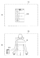
ここで、入力操作面21に相対する指の位置は、操作を行う指と入力操作面21との距離が最短となる点と定義される。図3は、非接触検知可能な入力操作面(タッチパネル面)21をXY平面、XY平面から垂直方向ユーザ側を+ZとしたときのXYZ空間を示している。本実施形態では、タッチパネルの指位置検出可能領域(ただしZ≧0のみ)において、操作を行う手(片手/両手操作のどちらも含む。)とタッチパネルの距離が最短となる点が、指位置(x,y,z)と定義される。z座標は、入力操作面21に対する指の近接距離に相当し、演算部251は、タッチセンサ22の容量増加量が容量増加量の上記所定の閾値以上となったとき、z=0と判定する。
Here, the position of the finger facing the
信号生成部252では、演算部251から送信された処理結果に基づき、表示素子24に表示させる表示画像を形成するための画像信号を生成する。この際、信号生成部252は、入力操作面21上の画像の検出対象のxy座標位置に対応する位置にポインタ等の補助画像を表示させる信号を生成することも可能である。また、信号生成部252は、検出対象の接触圧に応じて、補助画像の表示形態を変化させる信号を生成することも可能である。
The
制御部25の演算部251で算出された指のxy座標位置及び近接距離に関する操作信号と、信号生成部252で生成された画像信号とは、送受信器27を介してHMD1へ送信されるように構成される。また図示せずとも、入力デバイス2は、タッチセンサ22から出力される検出信号(アナログ信号)をデジタル信号に変換するA/Dコンバータや、デジタル信号をアナログ信号に変換するD/Aコンバータを含む。
The operation signal related to the xy coordinate position and proximity distance of the finger calculated by the
記憶部26は、RAM(Random Access Memory)、ROM(Read Only Memory)及びその他の半導体メモリ等で構成され、制御部25による種々の演算に用いられるプログラム等を格納する。例えば、ROMは、不揮発性メモリで構成され、制御部25に検出対象のxy座標位置及び近接距離の算出等の演算処理を実行させるためのプログラムや設定値を格納する。また、記憶部26は、例えば不揮発性の半導体メモリによって、検出対象のxy座標位置及び近接距離と、これらに対応して割り当てられた機能を実行するためのプログラム等を格納することが可能となる。さらに、半導体メモリ等に予め格納されたこれらのプログラムは、RAMにロードされ、制御部25の演算部251によって実行されるようにしてもよい。
The
送受信器27は、制御部25によって生成された各種制御信号を、例えば無線でHMD1へ送信可能に構成される。また送受信器27は、HMD1から送信される所定の信号を受信可能に構成される。一方、通信部28は、インターネット等の通信網と接続される。通信部28は、例えばアプリケーション等の所定のプログラムを入力デバイス2にダウンロードする際に用いられる。通信部28における情報の送受信は、LANケーブル等を用いた有線によるものでもよいし、高速データ通信等の無線によるものでもよい。
The
バッテリBTは、入力デバイス2の電源を構成し、筐体2A内部の各部へ必要な電力を供給する。バッテリBTは、一次電池でもよいし、二次電池でもよい。またバッテリBTは、太陽電池で構成されてもよい。さらに、入力デバイス2は、押圧により入力デバイス2の起動等を制御する図示しない外部スイッチを有することも可能である。
The battery BT constitutes a power source for the
入力デバイス2は、情報表示装置100に専用の装置として構成されてもよいが、携帯機器等のような独立した電子機器として構成されてもよい。これにより、HMD1に接続しない場合でも、タッチディスプレイ付きの情報表示端末としてHMD1とは独立して使用することが可能となる。
The
[HMD]
HMD1は透過型HMDであり、ユーザに外界を視認させつつ、その視野領域に所定の画像を提示することが可能に構成される。本実施形態に係るHMD1は、画像表示装置11と、支持部16とを有し、全体としてメガネ型の形状を有する。例えば、HMD1として透過型のHMDを採用することにより、入力デバイス2の操作中であっても外界を視認することが可能となり、操作中の安全性を向上させることができる。
[HMD]
The
支持部16は、ユーザの頭部に装着されることが可能であり、装着時に、後述する画像表示素子14がユーザの眼前に支持されるように構成される。支持部16の形状は特に限られないが、本実施形態において、全体としてメガネ型の形状とすることができる。支持部16は、例えば、ユーザの左右の耳に装着されることが可能なテンプル状構造を有する。支持部16の鼻梁付近には、例えばノーズパッド161が取り付けられることも可能である。また、イヤホン162が支持部16に装備されていてもよい。支持部16を構成する材料は、例えば、金属や合金、プラスチック等を採用することができ、特に制限されない。
The
画像表示装置11は、筐体11Aを含み、例えば支持部16の所定位置に配置される。画像表示装置11の配置は特に制限されず、例えば、筐体11Aが、ユーザの視野領域に含まれないように、ユーザの左右の目の外側に配置される。
The
図4は、画像表示装置11の内部構成を示すブロック図である。画像表示装置11は、本実施形態において、筐体11Aと、送受信器(受信部)12と、制御部13と、画像表示素子14と、記憶部15とを有する。本実施形態においては、制御部13が「表示処理部」を構成する。
FIG. 4 is a block diagram showing an internal configuration of the
送受信器12は、入力デバイス2の送受信器27から出力され、入力操作面21に近接する検出対象の相対位置(xy座標位置及び近接距離)に関する情報を含む操作信号を受信する。さらに、入力デバイス2の入力操作面21に表示される表示画像の画像信号を受信することも可能である。上記信号の伝送方法は特に限定されない。例えば、無線通信として、「Wi Fi」(登録商標)、「ZigBee」(登録商標)、「Bluetooth(登録商標)」などの機器間通信、またインターネットを経由した通信等を用いることができる。また、USB(Universal Serial Bus)、HDMI(High-Definition Multimedia Interface)等を介した有線によるものでも可能である。
The transmitter /
制御部13は、典型的には、CPUあるいはMPUで構成され、記憶部15に格納されたプログラムに従って各種機能を実行する。本実施形態において制御部13は、送受信器12により受信された操作信号及び画像信号に基づき、ユーザに提示される画像を画像表示素子14に形成させるための制御信号を生成する。これにより、例えば入力操作面21に表示された表示画像と同様の画像に、検出対象の位置を示す補助画像が重畳した操作画像を、画像表示素子14に表示させることが可能となる。補助画像の形状は特に限られず、例えば環状(リング状)のポインタ、あるいは輝度、彩度の変化した領域等で構成される。
The
上記操作画像から補助画像が除かれた画像は、典型的には、入力操作面21の表示画像と等価である。これにより、HMD1及び入力デバイス2双方の入力操作の一貫性・統一感が高められる。ここで「等価」とは、実質的に同一という意味であり、表示輝度や表示サイズ、縦横比(アスペクト比)等の厳密な意味での同一性は要求されない。したがって上記画像には、入力操作面21の表画像と同一の画像だけに限られず、例えば、表示画像と相似な画像(当該表示画像を拡大・縮小した画像)、表示画像に比べて歪んだ画像等が含まれる。さらにHMD1に表示される画像には、入力デバイス2の表示画像や上記補助画像だけでなく、他の画像も同時にあるいは選択的に表示されてもよい。
The image obtained by removing the auxiliary image from the operation image is typically equivalent to the display image on the
画像表示素子14は、本実施形態において、液晶表示素子(LCD)141と、光学系142とを有し、LCD141によって形成された画像を、光学系142を介してユーザに提示するように構成される。画像表示素子14は、入力デバイス2による入力操作あるいはHMD1に装備された適宜の入力装置による入力操作によって、ユーザへ提示される画像を任意の大きさに拡大あるいは縮小できるように構成されている。
In the present embodiment, the
LCD141は、複数の画素がマトリクス状に配置されている。LCD141は、LED(発光ダイオード)等からなる図示しない光源から入射される光を、制御部13によって生成された制御信号に応じて画素毎に変調し、ユーザに提示される画像を形成する光を出射する。LCD141は、例えば、R(赤),G(緑),B(青)の各色に対応する画像光を同時に出射する単板方式でもよいし、各色に対応する画像光を個々に出射する3板方式でもよい。
The
光学系142は、LCD141から出射された光を偏向し、ユーザの目に導くことが可能に構成される。光学系142は、例えば、全反射による導光が可能な透明基板からなる導光板と、回折反射が可能な反射型体積ホログラム回折格子等とで構成されることができる。導光板は、例えば、矩形または円形の平板形状等で形成され、メガネのレンズのようにユーザの眼前に配置される。ホログラム回折格子等は、導光板内に適宜配置され、LCD141から出射される光を反射させ、ユーザの目に導くことが可能に作製される。また、ホログラム回折格子以外にも、例えば反射板等を採用することができる。
The
このような構成の光学系142は、LCD141から出射された光が所定位置で反射されることで、ユーザの視野領域に操作画像を提示することが可能となる。また、導光板が透明基板で形成されることによって、ユーザに外界を視認させつつ、操作画像を視野領域内に重畳的に提示することが可能となる。
The
記憶部15は、RAM、ROM及びその他の半導体メモリ等で構成され、制御部13による種々の演算に用いられるプログラム等を格納する。
The
スピーカ17は、入力デバイス2より送信され、あるいは制御部13等によって生成された電気的な音声信号を物理的な振動に変換し、イヤホン162を介してユーザに音声を提供する。なお、スピーカ17の構成は特に限られない。
The
なお、画像表示装置11は、両目に対応して2個配置される構成に限られない。例えば、左右一方の目のみに対応して1個配置される構成とすることも可能である。
In addition, the
[情報表示装置の動作例]
次に、情報表示装置100の基本的な動作例について説明する。
[Operation example of information display device]
Next, a basic operation example of the
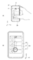
図5は、HMD1(制御部13)及び入力デバイス2(制御部25)の一動作例におけるフローチャートである。図6は、情報表示装置100の典型的な動作例を説明する図であり、(A)は、ユーザが入力操作を行っている入力デバイス2の入力操作面21を示し、(B)は、HMD1を介してユーザに提示される操作画面を示す。なお、図中のX軸方向及びY軸方向は、入力操作面21のX軸方向及びY軸方向にそれぞれ対応し、Z軸方向は、入力操作面21のZ軸方向に対応する。
FIG. 5 is a flowchart of an operation example of the HMD 1 (control unit 13) and the input device 2 (control unit 25). 6A and 6B are diagrams for explaining a typical operation example of the
起動された入力デバイス2の入力操作面21上には、例えば、多数のGUIが表示された画像v1(表示画像)が表示されている(図6(A))。画像v1は、例えば各種アプリケーションの選択画面であり、各GUIは、アプリケーション毎に割り当てられたアイコンである。
For example, an image v1 (display image) on which a large number of GUIs are displayed is displayed on the
この際、入力デバイス2と接続され、起動されたHMD1を装着したユーザにも、HMD1を介して視野領域に画像v1と同様の画像V1が提示される。
At this time, the user who is connected to the
入力デバイス2は、タッチセンサ22によって入力操作面21上でのユーザの指(検出対象)の近接を判定する(ステップST101)。近接が検出された際(ステップST101でYES)、タッチセンサ22は、指が近接した入力操作面21上のxy座標位置及び指の近接距離に関する検出信号を制御部25へ出力する。
The
制御部25の演算部251は、上記検出信号に基づいて、入力操作面21に近接する指のxy座標位置及びその近接距離を算出する(ステップST102)。演算部251によって算出されたxy座標位置に関する信号は、送受信器27に出力される。
Based on the detection signal, the
送受信器27は、HMD1の送受信器12に上記xy座標位置及び近接距離に関する操作信号を送信する。
The
HMD1の制御部13は、送受信器12で受信した操作信号及び画像信号に基づいて、画像V1に検出対象の位置を示す補助画像(ポインタP)が重畳した操作画像V10を制御する信号を生成する。この制御信号が出力された画像表示素子14は、ユーザに操作画像V10を提示する(ステップST103、図6(B))。これにより、ユーザは、手元の入力操作面21を見ずとも、HMD1によって提示される操作画像V10上のポインタPの動きを確認することで、所望の操作を行うことが可能となり、ユーザの直感に即した操作を行うことが可能となる。なお、この際、入力操作面21に表示される画像は、画像v1のみであってもよいし、画像v1にポインタ等が重畳された画像であってもよい。
Based on the operation signal and the image signal received by the
また、ユーザの指が入力操作面21上で移動した場合(図6(A),(B)における矢印参照)、経時的に変化するxy座標位置の情報がタッチセンサ22によって取得される。この情報は、入力デバイス2の制御部25によって操作信号として処理され、送受信器27、12を介してHMD1の制御部13へ出力される。これにより、制御部13は、上記操作信号に基づき、ポインタPを移動させるような制御信号をLCD141に出力することができ、ユーザの指の移動に応じて、画像V1の表示領域におけるポインタPを移動させることが可能となる。
When the user's finger moves on the input operation surface 21 (see arrows in FIGS. 6A and 6B), information on the xy coordinate position that changes with time is acquired by the
入力デバイス2の制御部25は、算出されたxy座標位置に最も近いGUI(以下、選択GUIとする)を選択候補とする(ステップST104)。これに対応して、入力操作面21及びHMD1に表示される画像v1、V10の選択候補のGUIは、例えば枠の色彩等の表示形態を変化させてもよい。またユーザは、HMD1によって表示された画像V10を視認することで、選択候補のGUIを確認することが可能となる。
The
制御部25は、経時的に指と入力操作面21との近接あるいは接触状態を判定する(ステップST101〜105)。ここで、ユーザが入力操作面21から指を所定以上離間させると、タッチセンサ22は、指が近接していないときの信号を出力する。制御部25は、当該タッチセンサ22の出力に基づいて、入力操作面21と指との非接触を判定する(ステップST105でNO)。
一方、ユーザが入力操作面21をタッチすると、タッチセンサ22は、指が接触しているときの信号を出力する。制御部25は、当該タッチセンサ22の出力に基づいて、ユーザの指が入力操作面21に接触していると判定する(ステップST105でYES)。
On the other hand, when the user touches the
選択候補GUIは、入力操作面21上の当該選択候補GUIの表示位置に対するユーザのタッチ操作によって選択(決定)される。制御部25は、タッチセンサ22の出力に基いて、演算部251において上記タッチ操作の有無を判定する。ここで、タッチ操作の有無は、タッチセンサ22から出力される容量値の変化量が所定の閾値以上であるか否かを基に判定される。入力操作面21に指が接触したとき(ステップST105でYES)、制御部25は、当該選択候補のGUIを選択GUIとして判定し、記憶部26に格納されたこの選択GUIに対応するプログラムを実行する(ステップST106)。起動したアプリケーション画像やウェブ画像(動画、静止画)は、入力操作面21だけでなく、HMD1の視野上にも表示される。
The selection candidate GUI is selected (determined) by the user's touch operation on the display position of the selection candidate GUI on the
一方、制御部25は、算出された近接距離が所定の閾値未満の場合(ステップST106でNO)、選択候補のGUIは選択されなかったものと判定する。この場合、制御部25は、ステップST101へ戻り、上述した処理を繰り返す。
On the other hand, when the calculated proximity distance is less than the predetermined threshold (NO in step ST106), the
近年、タッチディスプレイ上に表示されたオブジェクト(メニュー、操作アイコン等)に直接指を触れることによって情報を入力する、いわゆる絶対位置タッチ入力操作型の携帯機器が広く普及している。このような携帯機器は、その性質上、入力操作中は常に当該機器の画面及び指の位置を見続けなければならない。このため、歩行中の操作時には前方が不注意となりがちとなり、長時間の使用時は首や腕が疲れ易いという問題があった。また映像の表示領域すなわち機器のサイズに制限されてしまうため、表示が小さく見にくい場合がある。さらに入力操作時に指で表示が隠れてしまうという問題もあった。 2. Description of the Related Art In recent years, so-called absolute position touch input operation type portable devices that input information by directly touching an object (menu, operation icon, etc.) displayed on a touch display have become widespread. Due to the nature of such portable devices, the screen of the device and the position of the finger must always be viewed during the input operation. For this reason, the front tends to be careless during operation during walking, and the neck and arms tend to get tired when used for a long time. In addition, since the display area of the video, that is, the size of the device is limited, the display may be small and difficult to see. There is also a problem that the display is hidden with a finger during an input operation.
一方、従来のヘッドマウントディスプレイ(HMD)における入力操作は、例えば十字キー、トラックボール、タッチパッドなどの旧来型入力装置を用いるものが多く、絶対位置入力操作と比べると、直感性・操作性が劣っていた。また従来のHMDはその入力操作性の問題もあり、HMD用のインタラクティブなアプリケーションは少なく、一方的に映像・画像を表示し続けるようなもの(テレビジョン映像、ビデオ映像、スライドショーなど)に使用が限られていた。 On the other hand, the input operation in the conventional head mounted display (HMD) often uses a conventional input device such as a cross key, a trackball, and a touch pad, and has intuitiveness and operability as compared with the absolute position input operation. It was inferior. The conventional HMD also has a problem of input operability, and there are few interactive applications for the HMD, and it is used for ones that continue to display video and images unilaterally (television video, video video, slide show, etc.). It was limited.
ここで、タッチディスプレイを有する携帯機器の画面をHMDの視野上に表示し、かつこれまでと同等の絶対位置タッチ入力操作を実現できれば、タッチディスプレイ搭載機器における豊富な従来アプリケーションを、手元を見ることなく大画面で快適に使用することが可能となる。しかしながら、単にタッチディスプレイを有する携帯機器の画面をHMDの視野上に表示するだけでは、画面から指を離した際に指と画面との相対位置が分からなくなり、操作が困難となる。一方、画面を見ずに操作できるように旧来型入力装置をはじめとした専用の入力装置を使用する場合、既に絶対位置タッチ入力操作に最適化されている従来アプリケーションを修正したり、新たに作り直したりする必要がある。 Here, if you can display the screen of a mobile device with a touch display on the field of view of the HMD and achieve the same absolute position touch input operation as before, you can see a wide range of conventional applications on devices with a touch display. And can be used comfortably on a large screen. However, simply displaying the screen of a portable device having a touch display on the field of view of the HMD makes it difficult to know the relative position between the finger and the screen when the finger is removed from the screen. On the other hand, when using a dedicated input device such as a conventional input device so that it can be operated without looking at the screen, the existing application already optimized for absolute position touch input operation has been modified or recreated. It is necessary to do.
これに対して本実施形態のHMD1あるいは情報表示装置100においては、入力操作面21に表示される画像v1に指の位置を示す補助画像(ポインタP)が重畳した操作画像V10がHMD1の視野上に表示されるように構成される。これによりユーザは、手元の入力操作面21を見ずとも、HMD1によって提示される操作画像V10上のポインタPの動きを確認することで所望の操作が可能となる。また、入力操作面21から指が離れた場合でも指の座標位置が操作画像V10上に表示されるため、直感的で操作性のよい絶対位置タッチ入力操作が可能となる。
On the other hand, in the
また本実施形態によれば、操作画像V10をHMD1によって任意の大きさに表示することができるので、ユーザの希望に応じた大画面による快適な使用環境を提供することができる。さらにHMD1で表示される画面は指で隠れてしまうことがないため、誤操作や視認性の低下を防止することが可能となる。
Further, according to the present embodiment, since the operation image V10 can be displayed in an arbitrary size by the
さらに本実施形態によれば、HMD1として透過型ヘッドマウントディスプレイを採用しているため、前方の視野を確保しつつ入力デバイス2を操作することができる。
Furthermore, according to the present embodiment, since the transmissive head mounted display is adopted as the
<第2の実施形態>
図7〜図9は、本技術の第2の実施形態を説明する図である。図7は本実施形態に係る入力デバイスの内部構成を示すブロック図であり、図8は、本実施形態のヘッドマウントディスプレイに係る画像表示装置の内部構成を示すブロック図である。図9は、情報表示装置の典型的な動作例を説明する図であり、(A)は、ユーザが入力操作を行っている入力デバイスの入力操作面を示し、(B)は、HMDを介してユーザに提示される操作画面を示す。本実施形態では、第1の実施形態の構成および作用と同様な部分についてはその説明を省略または簡略化し、第1の実施形態と異なる部分を中心に説明する。
<Second Embodiment>
7 to 9 are diagrams illustrating a second embodiment of the present technology. FIG. 7 is a block diagram illustrating an internal configuration of the input device according to the present embodiment, and FIG. 8 is a block diagram illustrating an internal configuration of the image display apparatus according to the head mounted display of the present embodiment. FIG. 9 is a diagram for explaining a typical operation example of the information display device. FIG. 9A shows an input operation surface of an input device on which a user performs an input operation, and FIG. 9B shows an operation via an HMD. The operation screen presented to the user is shown. In the present embodiment, the description of the same parts as those of the first embodiment will be omitted or simplified, and different parts from the first embodiment will be mainly described.
本実施形態の入力デバイス20は、表示素子を有さず、入力操作面210には画像が表示されない点で、上述の第1の実施形態と異なる。すなわち、タッチセンサ220によるxy座標位置の検出信号が、操作信号として、送受信器270を介してHMD10へ送信されることが可能に構成される。これにより、図9(A)のように、入力操作面210には画像が表示されず、入力デバイス20は、いわゆるタッチパネル(タッチパッド)のみを有する構成とすることができる。すなわち、本実施形態に係る入力デバイス20は、HMD10に専用のリモートコントローラとすることが可能である。
The
入力デバイス20は、タッチセンサ220を駆動する駆動回路を含む制御部250と、送受信器270、必要に応じて搭載される通信部280の動作を制御するプログラム等を格納する記憶部260とを有する。入力デバイス20の入力操作面210は、本実施形態において、検出対象による入力操作が行われるのみであるため、光透過性を有しない材料で構成することが可能である。タッチセンサ220は、上述の第1の実施形態において説明したタッチセンサ22と同様の構成を有しているため、その説明は省略する。
The
HMD10の画像表示装置110に係る制御部130は、本実施形態において、演算部131と表示処理部132とを有する。演算部131では、入力デバイス20のタッチセンサ220から出力される操作信号に基づいて、指のxy座標位置を算出する。表示処理部132では、演算部131から入力された処理結果に基づき、画像表示素子140に表示させる画像を形成するための画像信号を生成する。この際、表示処理部132は、入力操作面210上の画像の検出対象のxy座標位置に対応する位置にポインタ等の補助画像を表示させる信号を生成する。これにより、図9(B)に示されるように、HMD10は、第1の実施形態に係る操作画像V10と同様の操作画像V30をユーザに表示することが可能となる。
The
さらに、HMD10によってユーザに提示される画像は、インターネット等から入力デバイス20の通信部280を介して取得されてもよい。また、HMD10に通信部170を設けて、HMD10によって直接取得された情報に基づいて上記画像が生成されてもよい。さらには操作画面の表示に必要なプログラム(オペレーティングシステム、アプリケーションソフトウェア)がHMD10の制御部130によって実行可能なように、HMD10の記憶部150に格納されてもよい。
Furthermore, the image presented to the user by the
本実施形態においては、入力デバイス20の構成を簡略化することが可能である。これにより、入力デバイス20を小型化、軽量化することが可能となり、長時間のタッチ操作でも疲れにくく、持ち運びも容易な入力デバイス20を提供することが可能となる。
In the present embodiment, the configuration of the
<第3の実施形態>
図10は、本技術の第3の実施形態に係る入力デバイスの内部構成を示すブロック図である。本実施形態では、第1の実施形態の構成および作用と同様な部分についてはその説明を省略または簡略化し、第1の実施形態と異なる部分を中心に説明する。
<Third Embodiment>
FIG. 10 is a block diagram illustrating an internal configuration of the input device according to the third embodiment of the present technology. In the present embodiment, the description of the same parts as those of the first embodiment will be omitted or simplified, and different parts from the first embodiment will be mainly described.
本実施形態の入力デバイス30は、HMD1と通信可能な携帯端末31と、携帯端末31と無線または有線で電気的に接続可能なセンサパネル32とを有しており、携帯端末31とセンサパネル32とがそれぞれ別個の部材として構成されている点で、第1の実施形態と異なっている。
The
携帯端末31は、第1の実施形態に係る入力デバイス2と同様の機能を有するが、ユーザの操作位置(指)を検出するタッチセンサを備えておらず、センサパネル32から出力される操作位置の座標信号に基づいて、制御部25により座標位置及び近接距離を算出するように構成されている。携帯端末31の送受信器27は、センサパネル32から送信されるタッチセンサ322の出力を受信する機能と、制御部25において生成された操作信号をHMD1へ送信する機能とを有する。
The
センサパネル32は、入力操作面321と、入力操作面321に対する検出対象の座標位置及び近接距離に関する情報を出力可能なタッチセンサ322と、タッチセンサ322を駆動する駆動部323と、タッチセンサ322の出力を携帯端末31へ送信する送信器324とを有する。タッチセンサ322は、上述の第1の実施形態において説明したタッチセンサ22と同様の構成を有しているため、その説明は省略する。
The
本実施形態に係る情報表示装置においては、センサパネル32に入力された入力信号は携帯端末31を介してHMD1へ送信される。このため、携帯端末31がユーザの指の非接触検知機能を備えていない場合でも、上述の第1の実施形態と同様の作用効果を得ることが可能となる。
In the information display device according to the present embodiment, an input signal input to the
<第4の実施形態>
図11〜図13は本技術の第4の実施形態を説明する図である。本実施形態では、第1の実施形態の構成および作用と同様な部分については同一の符号を付すとともにその説明を省略または簡略化し、第1の実施形態と異なる部分を中心に説明する。
<Fourth Embodiment>
11 to 13 are diagrams illustrating a fourth embodiment of the present technology. In the present embodiment, the same components as those in the first embodiment will be denoted by the same reference numerals, the description thereof will be omitted or simplified, and the description will focus on portions that are different from the first embodiment.
本実施形態においては、入力操作面21に対する検出対象(指)の近接距離に応じて補助画像(ポインタ)P4の表示形態を変化させる点で第1の実施形態と異なる。
This embodiment is different from the first embodiment in that the display form of the auxiliary image (pointer) P4 is changed according to the proximity distance of the detection target (finger) to the
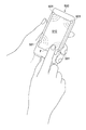
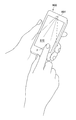
図11及び図12は、入力操作面21と指Fとの距離zが大きいほど画像V4上の環状のポインタP4が大きく表示される例を示している。図11(A),(B)は、入力操作面21から指Fが距離zだけ離れているときの様子(第1の状態)を示し、図12(A),(B)は、入力操作面21に指Fが距離zよりも小さい距離で接近しているときの様子(第2の状態)を示している。
11 and 12 show an example in which the annular pointer P4 on the image V4 is displayed larger as the distance z between the
このように指Fと入力操作面21との相対距離に応じてポインタP4の大きさを変化させることで、ユーザにとっては入力操作面21に対する指Fの離間距離あるいは近接距離の判断が容易となる。これにより絶対位置タッチ入力操作性を高めることができる。
In this way, by changing the size of the pointer P4 according to the relative distance between the finger F and the
一方、図13(A)は上記第1の状態における画像V4上のポインタP4の表示形態を示し、図13(B)は上記第2の状態における画像V4上のポインタP4の表示形態を示している。本例では、入力操作面21に対して指Fが接近するほどポインタP4の表示濃度を濃くするようにしている。このように指Fと入力操作面21との相対距離に応じてポインタP4の表示濃度を変化させることによっても、上述と同様の作用効果を得ることができる。
13A shows a display form of the pointer P4 on the image V4 in the first state, and FIG. 13B shows a display form of the pointer P4 on the image V4 in the second state. Yes. In this example, the display density of the pointer P4 is increased as the finger F approaches the
なお上記以外にも、ポインタの表示色、ポインタの透過度、ポインタの明るさ(コントラスト)等の表示形態を変化させることで、入力操作面に対する指の近接距離に応じてポインタの表示形態を変化させてもよい。 In addition to the above, changing the display form such as the pointer display color, pointer transparency, and pointer brightness (contrast) changes the pointer display form according to the proximity distance of the finger to the input operation surface. You may let them.
<第5の実施形態>
次に、図14及び図15を参照して本技術の第5の実施形態について説明する。図14(A)及び図15(A)はそれぞれユーザが入力操作を行っている入力デバイスの入力操作面を示し、図14(B)及び図15(B)はそれぞれHMDを介してユーザに提示される操作画面を示す。本実施形態では、第1の実施形態の構成および作用と同様な部分については同一の符号を付すとともにその説明を省略または簡略化し、第1の実施形態と異なる部分を中心に説明する。
<Fifth Embodiment>
Next, a fifth embodiment of the present technology will be described with reference to FIGS. 14 and 15. FIG. 14A and FIG. 15A each show the input operation surface of the input device on which the user performs an input operation, and FIG. 14B and FIG. 15B are each presented to the user via the HMD. The operation screen to be displayed is shown. In the present embodiment, the same components as those in the first embodiment will be denoted by the same reference numerals, the description thereof will be omitted or simplified, and the description will focus on portions that are different from the first embodiment.
本実施形態では、入力デバイス2の表示画像v1を含む他の画像がHMD1の視野上に表示される点で、上述の第1の実施形態と異なる。例えば図14(A),(B)に示す例では、HMD1の視野上に表示される操作画像V51には、表示画像v1に対応する画像V1上に、ポインタPだけでなく、入力デバイス2の外観を表す画像V2がさらに重畳して表示される。これによりHMD1を装着した状態で実際に入力デバイス2を見ながら操作している感覚をユーザに提供することができる。
This embodiment is different from the first embodiment described above in that other images including the display image v1 of the
次に、図15(A)に示す入力デバイス2の表示画像v1は、画面下方から上方へ向けた指の移動操作によって複数の指示項目S1,S2,S3,S4が画面下方から上方へ向けて順に表示された様子を示している。一方、図15(B)に示すようにHMD1の視野には、指示項目の次候補である指示項目S5が指示項目S4の後に続けて表示された操作画像V52が表示される。このような操作画像V52は、入力デバイス2から送信される操作信号に含まれる画像信号に基づいてHMD1において形成される。なお、表示画像v1に表示されていない指示項目S5は実際には選択操作ができないため、ユーザにとって識別可能に、他の指示項目S1〜S4とは異なる形態で指示項目S5を表示するようにしてもよい。
Next, in the display image v1 of the
上記の例によれば、ユーザに対して入力操作のアシスト機能を実現でき、より快適な操作環境を提供することが可能となる。またこのような機能は、選択候補の一覧表示だけでなく、ナビゲーション用の地図画像等にも適用することができる。 According to the above example, the assist function of the input operation can be realized for the user, and a more comfortable operation environment can be provided. Such a function can be applied not only to a list of selection candidates but also to a map image for navigation.
<第6の実施形態>
次に、図16(A),(B)を参照して本技術の第5の実施形態について説明する。本実施形態では、第1の実施形態の構成および作用と同様な部分については同一の符号を付すとともにその説明を省略または簡略化し、第1の実施形態と異なる部分を中心に説明する。
<Sixth Embodiment>
Next, a fifth embodiment of the present technology will be described with reference to FIGS. In the present embodiment, the same components as those in the first embodiment will be denoted by the same reference numerals, the description thereof will be omitted or simplified, and the description will focus on portions that are different from the first embodiment.
本実施形態のHMDは、当該HMDの視野上に表示される操作画像V10の表示領域を任意の操作で他の表示領域に、他の表示形態で表示することが可能に構成されている。 The HMD of the present embodiment is configured such that the display area of the operation image V10 displayed on the field of view of the HMD can be displayed in another display area in another display form by an arbitrary operation.
例えば本実施形態のHMDは、図16(A)に示すように操作画像V10を視野FVの中央付近に表示するように設定することができる。透過型のHMDにおいては、前方の視界に操作画像V10が重なって表示されるため、混雑した歩道を歩行する場合等においては操作画像V10が邪魔になることがある。そこで本実施形態のHMDにおいては、所定の操作によって操作画像V10を視野FVの端に移動したり、操作画像V10の表示サイズを小さくしたりすることで、図16(B)に示すように例えば前方から対向する歩行者W等の視認を確保する。これにより操作画像V10の表示が安全な歩行の妨げとなることを防止することができる。 For example, the HMD of this embodiment can be set so that the operation image V10 is displayed near the center of the field of view FV as shown in FIG. In the transmissive HMD, the operation image V10 is displayed so as to overlap the field of view in the front, so the operation image V10 may be an obstacle when walking on a crowded sidewalk. Therefore, in the HMD of this embodiment, the operation image V10 is moved to the end of the visual field FV by a predetermined operation, or the display size of the operation image V10 is reduced, for example, as shown in FIG. The visual recognition of the pedestrian W etc. which opposes from the front is ensured. Thereby, it can prevent that the display of the operation image V10 obstructs a safe walk.
上記所定の操作としては、HMDに別途装備された所定のスイッチの入力操作であってもよいし、入力デバイス2の入力操作面21における所定のジェスチャ入力等であってもよい。あるいは、当該HMDに角速度センサや加速度センサ等のモーションセンサを搭載し、HMDが装着した頭部を所定の方向へ振る等のユーザの所定の動きを検出して操作画像V10の表示領域や表示サイズ等を変更するようにしてもよい。
The predetermined operation may be an input operation of a predetermined switch separately provided in the HMD, a predetermined gesture input on the
以上、本技術の実施形態について説明したが、本技術はこれに限定されることはなく、本技術の技術的思想に基づいて種々の変形が可能である。 The embodiment of the present technology has been described above, but the present technology is not limited to this, and various modifications can be made based on the technical idea of the present technology.
例えば、以上の実施形態において、入力デバイスがユーザが把持して使用する携帯端末等であると説明したが、これに限られない。例えば、ユーザの手首に装着される腕時計型であってもよいし、ユーザの腕に装着されるリストバンド型であってもよい。また、衣服に装着または付着する形態であってもよい。このように、本技術においては、入力操作面に対して検出対象が接触することができる機器であれば、様々な形態の入力デバイスを用いることが可能である。 For example, in the above embodiments, the input device is described as a portable terminal or the like that is held and used by the user, but the present invention is not limited to this. For example, it may be a wristwatch type worn on the user's wrist or a wristband type worn on the user's arm. Further, it may be in the form of being attached to or attached to clothes. As described above, in the present technology, various types of input devices can be used as long as the detection target can contact the input operation surface.
また、以上の実施形態では透過型のHMDとして説明したが、これに限られず、非透過型のHMDとすることも可能である。この場合も、ユーザは、HMDによって提示される画像を視認しつつ操作を行うことによって、入力デバイスの入力操作面を見ずとも直感に即した操作が可能となる。 Moreover, although the above embodiment demonstrated as a transmissive | pervious HMD, it is not restricted to this, It can also be set as a non-transmissive | pervious HMD. Also in this case, the user can perform an operation in an intuitive manner without looking at the input operation surface of the input device by performing the operation while visually recognizing the image presented by the HMD.
また、HMDに撮像素子を搭載し、外部を撮影可能に構成することもできる。これにより、例えば撮影した画像をHMD及び入力デバイスに表示させることも可能となる。 In addition, an image sensor can be mounted on the HMD so that the outside can be imaged. As a result, for example, a captured image can be displayed on the HMD and the input device.
以上の実施形態においては、補助画像としてのポインタの形状を環状の例で説明したが、勿論これに限られない。例えば、矢印、三角形、四角形、円形等の任意の形状を採用することが可能である。 In the above embodiment, the shape of the pointer as the auxiliary image has been described as an annular example, but the present invention is not limited to this. For example, any shape such as an arrow, a triangle, a quadrangle, and a circle can be employed.
また、以上の実施形態では、入力操作面に対する指の近接の検出に静電容量式のタッチセンサが用いられたが、これに限られない。例えば図17に示すように、矩形の入力操作面510の四隅位置に距離センサ501をそれぞれ配備した入力デバイス500や、図18に示すように入力操作面610の近傍にカメラ601を配備した入力デバイス600も本技術に適用可能である。図17に示す入力デバイス500においては、各距離センサ501の出力に基づき、例えば三角測距法を応用することで、入力操作面410上の指Fの座標位置及び近接距離が検出される。また図18に示す入力デバイス600においては、カメラ601で取得される指Fの画像を処理することで、入力操作面410上の指Fの座標位置及び近接距離が検出される。
In the above embodiment, the capacitive touch sensor is used to detect the proximity of the finger to the input operation surface. However, the present invention is not limited to this. For example, as shown in FIG. 17, an
なお、本技術は以下のような構成も採ることができる。
(1)入力デバイスから出力される、入力操作面に近接する検出対象の相対位置に関する情報を含む操作信号を受信する受信部と、
ユーザに提示される画像を形成する画像表示素子と、
前記操作信号に基づき、前記画像に前記検出対象の位置を示す補助画像が重畳した操作画像を、前記画像表示素子に表示させる表示処理部と
を具備するヘッドマウントディスプレイ。
(2)前記(1)に記載のヘッドマウントディスプレイであって、
前記受信部は、前記入力デバイスから出力される画像信号をさらに受信し、
前記表示処理部は、前記画像信号に基づき、前記画像を前記画像表示素子に表示させる
ヘッドマウントディスプレイ。
(3)前記(1)又は(2)に記載のヘッドマウントディスプレイであって、
前記表示処理部は、前記操作信号に基づき、前記画像の表示領域において前記補助画像を移動させる
ヘッドマウントディスプレイ。
(4)前記(1)から(3)のいずれか1つに記載のヘッドマウントディスプレイであって、
前記操作信号は、前記入力操作面に対する前記検出対象の近接距離に関する情報を含み、
前記表示処理部は、前記入力操作面に対する前記検出対象の近接距離に応じて前記補助画像の表示形態を変化させる
ヘッドマウントディスプレイ。
(5)前記(1)から(4)のいずれか1つに記載のヘッドマウントディスプレイであって、
前記操作信号に基づいて、前記入力操作面上の前記検出対象の座標位置を算出する演算部をさらに具備し、
前記表示処理部は、前記演算部で算出された前記検出対象の座標位置に基づき、前記操作画像を前記画像表示素子に表示させる
ヘッドマウントディスプレイ。
(6)入力操作面と、前記入力操作面に対する検出対象の近接を検出し、前記入力操作面上の前記検出対象の座標位置に関する情報を出力するセンサ部と、を有する入力デバイスと、
ユーザに提示される画像を形成する画像表示素子と、前記センサ部の出力に基づき、前記画像に前記検出対象の位置を示す補助画像が重畳した操作画像を、前記画像表示素子に形成させる表示処理部と、を有するヘッドマウントディスプレイと
を具備する情報表示装置。
(7)前記(6)に記載の情報表示装置であって、
前記入力デバイスは、
前記入力操作面に画像を表示させる表示素子をさらに有し、
前記ヘッドマウントディスプレイは、前記入力操作面に表示される表示画像に前記補助画像を重畳させた画像を前記操作画像として表示する
情報表示装置。
(8)前記(6)又は(7)に記載の情報表示装置であって、
前記センサ部は、前記入力操作面と前記検出対象との間の静電容量の変化を検出する静電容量センサを含む
情報表示装置。
(9)前記(6)から(8)のいずれか1つに記載の情報表示装置であって、
前記センサ部は、前記入力操作面上における前記検出対象の動きを検出し、
前記ヘッドマウントディスプレイは、検出された前記検出対象の動きに応じて移動する前記補助画像を表示する
情報表示装置。
(10)前記(6)から(9)のいずれか1つに記載の情報表示装置であって、
前記ヘッドマウントディスプレイは、前記入力操作面に対する前記検出対象の近接距離に応じて、前記補助画像の表示形態を変化させる
情報表示装置。
(11)前記(7)に記載の情報表示装置であって、
前記ヘッドマウントディスプレイは、前記表示画像の周囲に前記入力デバイスの外観を表す画像をさらに表示する
情報表示装置。
(12)入力操作面と、前記入力操作面に対する検出対象の近接を検出するセンサ部と、を有する入力デバイスと、
ユーザに提示される画像を形成する画像表示素子と、前記センサ部の出力に基づいて前記入力操作面上の前記検出対象の座標位置を算出する演算部と、前記演算部で算出された前記検出対象の座標位置に基づき、前記画像に検出対象の位置を示す補助画像が重畳した操作画像を前記画像表示素子に形成させる表示処理部と、を有するヘッドマウントディスプレイと
を具備する情報表示装置。
In addition, this technique can also take the following structures.
(1) a receiving unit that receives an operation signal that is output from an input device and includes information on a relative position of a detection target that is close to the input operation surface;
An image display element for forming an image presented to a user;
And a display processing unit configured to display, on the image display element, an operation image in which an auxiliary image indicating the position of the detection target is superimposed on the image based on the operation signal.
(2) The head mounted display according to (1),
The receiving unit further receives an image signal output from the input device,
The display processing unit displays the image on the image display element based on the image signal.
(3) The head mounted display according to (1) or (2),
The display processing unit moves the auxiliary image in a display area of the image based on the operation signal.
(4) The head mounted display according to any one of (1) to (3),
The operation signal includes information on a proximity distance of the detection target to the input operation surface,
The display processing unit changes a display form of the auxiliary image according to a proximity distance of the detection target with respect to the input operation surface.
(5) The head mounted display according to any one of (1) to (4),
Based on the operation signal, further comprising a calculation unit for calculating the coordinate position of the detection target on the input operation surface,
The display processing unit displays the operation image on the image display element based on the coordinate position of the detection target calculated by the calculation unit.
(6) An input device having an input operation surface and a sensor unit that detects the proximity of the detection target to the input operation surface and outputs information on the coordinate position of the detection target on the input operation surface;
An image display element that forms an image presented to a user, and a display process that causes the image display element to form an operation image in which an auxiliary image indicating the position of the detection target is superimposed on the image based on the output of the sensor unit An information display device comprising: a head-mounted display having a unit.
(7) The information display device according to (6),
The input device is
A display element for displaying an image on the input operation surface;
The head mounted display displays an image obtained by superimposing the auxiliary image on a display image displayed on the input operation surface as the operation image.
(8) The information display device according to (6) or (7),
The sensor unit includes a capacitance sensor that detects a change in capacitance between the input operation surface and the detection target.
(9) The information display device according to any one of (6) to (8),
The sensor unit detects a movement of the detection target on the input operation surface;
The head mounted display displays the auxiliary image that moves in accordance with the detected movement of the detection target.
(10) The information display device according to any one of (6) to (9),
The head-mounted display changes the display form of the auxiliary image according to the proximity distance of the detection target to the input operation surface.
(11) The information display device according to (7),
The head mounted display further displays an image representing an appearance of the input device around the display image.
(12) An input device having an input operation surface and a sensor unit that detects the proximity of a detection target to the input operation surface;
An image display element that forms an image presented to a user, a calculation unit that calculates the coordinate position of the detection target on the input operation surface based on an output of the sensor unit, and the detection calculated by the calculation unit An information display device, comprising: a display processing unit configured to form, on the image display element, an operation image in which an auxiliary image indicating a position of a detection target is superimposed on the image based on a coordinate position of the target.
1・・・HMD(ヘッドマウントディスプレイ)
2,20,30・・・入力デバイス
13,130・・・制御部(表示処理部)
131・・・演算部
132・・・表示処理部
14,140・・・画像表示素子
21,210・・・入力操作面
22,220・・・タッチセンサ(センサ部)
24・・・表示素子
100・・・情報表示装置
P・・・ポインタ(補助画像)
V10・・・操作画像
1 ... HMD (Head Mounted Display)
2, 20, 30 ...
131 ...
24: Display element 100: Information display device P: Pointer (auxiliary image)
V10 ... Operation image
Claims (12)
ユーザに提示される画像を形成する画像表示素子と、
前記操作信号に基づき、前記画像に前記検出対象の位置を示す補助画像が重畳した操作画像を、前記画像表示素子に表示させる表示処理部と
を具備するヘッドマウントディスプレイ。 A receiving unit that receives an operation signal that is output from the input device and includes information on a relative position of a detection target that is close to the input operation surface;
An image display element for forming an image presented to a user;
And a display processing unit configured to display, on the image display element, an operation image in which an auxiliary image indicating the position of the detection target is superimposed on the image based on the operation signal.
前記受信部は、前記入力デバイスから出力される画像信号をさらに受信し、
前記表示処理部は、前記画像信号に基づき、前記画像を前記画像表示素子に表示させる
ヘッドマウントディスプレイ。 The head mounted display according to claim 1,
The receiving unit further receives an image signal output from the input device,
The display processing unit displays the image on the image display element based on the image signal.
前記表示処理部は、前記操作信号に基づき、前記画像の表示領域において前記補助画像を移動させる
ヘッドマウントディスプレイ。 The head mounted display according to claim 1,
The display processing unit moves the auxiliary image in a display area of the image based on the operation signal.
前記操作信号は、前記入力操作面に対する前記検出対象の近接距離に関する情報を含み、
前記表示処理部は、前記入力操作面に対する前記検出対象の近接距離に応じて前記補助画像の表示形態を変化させる
ヘッドマウントディスプレイ。 The head mounted display according to claim 1,
The operation signal includes information on a proximity distance of the detection target to the input operation surface,
The display processing unit changes a display form of the auxiliary image according to a proximity distance of the detection target with respect to the input operation surface.
前記操作信号に基づいて、前記入力操作面上の前記検出対象の座標位置を算出する演算部をさらに具備し、
前記表示処理部は、前記演算部で算出された前記検出対象の座標位置に基づき、前記操作画像を前記画像表示素子に表示させる
ヘッドマウントディスプレイ。 The head mounted display according to claim 1,
Based on the operation signal, further comprising a calculation unit for calculating the coordinate position of the detection target on the input operation surface,
The display processing unit displays the operation image on the image display element based on the coordinate position of the detection target calculated by the calculation unit.
ユーザに提示される画像を形成する画像表示素子と、前記センサ部の出力に基づき、前記画像に前記検出対象の位置を示す補助画像が重畳した操作画像を、前記画像表示素子に形成させる表示処理部と、を有するヘッドマウントディスプレイと
を具備する情報表示装置。 An input device comprising: an input operation surface; and a sensor unit that detects the proximity of the detection target to the input operation surface and outputs information on the coordinate position of the detection target on the input operation surface;
An image display element that forms an image presented to a user, and a display process that causes the image display element to form an operation image in which an auxiliary image indicating the position of the detection target is superimposed on the image based on the output of the sensor unit An information display device comprising: a head-mounted display having a unit.
前記入力デバイスは、
前記入力操作面に画像を表示させる表示素子をさらに有し、
前記ヘッドマウントディスプレイは、前記入力操作面に表示される表示画像に前記補助画像を重畳させた画像を前記操作画像として表示する
情報表示装置。 The information display device according to claim 6,
The input device is
A display element for displaying an image on the input operation surface;
The head mounted display displays an image obtained by superimposing the auxiliary image on a display image displayed on the input operation surface as the operation image.
前記センサ部は、前記入力操作面と前記検出対象との間の静電容量の変化を検出する静電容量センサを含む
情報表示装置。 The information display device according to claim 6,
The sensor unit includes a capacitance sensor that detects a change in capacitance between the input operation surface and the detection target.
前記センサ部は、前記入力操作面上における前記検出対象の動きを検出し、
前記ヘッドマウントディスプレイは、検出された前記検出対象の動きに応じて移動する前記補助画像を表示する
情報表示装置。 The information display device according to claim 6,
The sensor unit detects a movement of the detection target on the input operation surface;
The head mounted display displays the auxiliary image that moves in accordance with the detected movement of the detection target.
前記ヘッドマウントディスプレイは、前記入力操作面に対する前記検出対象の近接距離に応じて、前記補助画像の表示形態を変化させる
情報表示装置。 The information display device according to claim 6,
The head-mounted display changes the display form of the auxiliary image according to the proximity distance of the detection target to the input operation surface.
前記ヘッドマウントディスプレイは、前記表示画像の周囲に前記入力デバイスの外観を表す画像をさらに表示する
情報表示装置。 The information display device according to claim 7,
The head mounted display further displays an image representing an appearance of the input device around the display image.
ユーザに提示される画像を形成する画像表示素子と、前記センサ部の出力に基づいて前記入力操作面上の前記検出対象の座標位置を算出する演算部と、前記演算部で算出された前記検出対象の座標位置に基づき、前記画像に検出対象の位置を示す補助画像が重畳した操作画像を前記画像表示素子に形成させる表示処理部と、を有するヘッドマウントディスプレイと
を具備する情報表示装置。 An input device having an input operation surface and a sensor unit that detects the proximity of a detection target to the input operation surface;
An image display element that forms an image presented to a user, a calculation unit that calculates the coordinate position of the detection target on the input operation surface based on an output of the sensor unit, and the detection calculated by the calculation unit An information display device, comprising: a display processing unit configured to form, on the image display element, an operation image in which an auxiliary image indicating a position of a detection target is superimposed on the image based on a coordinate position of the target.
Priority Applications (6)
| Application Number | Priority Date | Filing Date | Title |
|---|---|---|---|
| JP2011275573A JP2013125247A (en) | 2011-12-16 | 2011-12-16 | Head-mounted display and information display apparatus |
| CN201280060735.2A CN103998970A (en) | 2011-12-16 | 2012-12-13 | Head-mounted display and information display apparatus |
| US14/363,715 US10191281B2 (en) | 2011-12-16 | 2012-12-13 | Head-mounted display for visually recognizing input |
| KR1020147014870A KR20140102663A (en) | 2011-12-16 | 2012-12-13 | Head-mounted display and information display apparatus |
| EP12806716.2A EP2791725A1 (en) | 2011-12-16 | 2012-12-13 | Head-mounted display and information display apparatus |
| PCT/JP2012/007974 WO2013088725A1 (en) | 2011-12-16 | 2012-12-13 | Head-mounted display and information display apparatus |
Applications Claiming Priority (1)
| Application Number | Priority Date | Filing Date | Title |
|---|---|---|---|
| JP2011275573A JP2013125247A (en) | 2011-12-16 | 2011-12-16 | Head-mounted display and information display apparatus |
Publications (2)
| Publication Number | Publication Date |
|---|---|
| JP2013125247A true JP2013125247A (en) | 2013-06-24 |
| JP2013125247A5 JP2013125247A5 (en) | 2015-01-22 |
Family
ID=47436152
Family Applications (1)
| Application Number | Title | Priority Date | Filing Date |
|---|---|---|---|
| JP2011275573A Abandoned JP2013125247A (en) | 2011-12-16 | 2011-12-16 | Head-mounted display and information display apparatus |
Country Status (6)
| Country | Link |
|---|---|
| US (1) | US10191281B2 (en) |
| EP (1) | EP2791725A1 (en) |
| JP (1) | JP2013125247A (en) |
| KR (1) | KR20140102663A (en) |
| CN (1) | CN103998970A (en) |
| WO (1) | WO2013088725A1 (en) |
Cited By (20)
| Publication number | Priority date | Publication date | Assignee | Title |
|---|---|---|---|---|
| JP2015049883A (en) * | 2013-09-05 | 2015-03-16 | セイコーエプソン株式会社 | Head-mounted type display device, method for controlling head-mounted type display device, and image display system |
| JP2015090530A (en) * | 2013-11-05 | 2015-05-11 | セイコーエプソン株式会社 | Image display system, method of controlling image display system, and head-mounted display device |
| KR20160016524A (en) * | 2014-07-31 | 2016-02-15 | 삼성전자주식회사 | Wearable glasses and method for displaying image therethrough |
| JP2016081408A (en) * | 2014-10-21 | 2016-05-16 | 株式会社コロプラ | Screen operation system by means of head-mounted display and controller cooperating with each other, program, and method |
| JP2016180986A (en) * | 2016-04-28 | 2016-10-13 | カシオ計算機株式会社 | Display system, display terminal, display method, and program |
| JPWO2015029222A1 (en) * | 2013-08-30 | 2017-03-02 | 富士通株式会社 | Information processing apparatus, display control program, and display control method |
| JP2017062559A (en) * | 2015-09-24 | 2017-03-30 | 株式会社コロプラ | Computer program for three-axially operating object in virtual space |
| JP2017068797A (en) * | 2015-10-02 | 2017-04-06 | 富士通株式会社 | Input support system and electronic apparatus |
| JP2017516186A (en) * | 2014-03-14 | 2017-06-15 | 株式会社ソニー・インタラクティブエンタテインメント | Game console with space sensing |
| JP2018508909A (en) * | 2015-03-20 | 2018-03-29 | 華為技術有限公司Huawei Technologies Co.,Ltd. | Intelligent interaction method, apparatus and system |
| JP2018128510A (en) * | 2017-02-06 | 2018-08-16 | 株式会社大林組 | Education support system, education support method, and education support program |
| US10095266B2 (en) | 2016-01-28 | 2018-10-09 | Colopl, Inc. | System and method for interfacing between a display and a controller |
| JP2018160249A (en) * | 2018-05-14 | 2018-10-11 | 株式会社ソニー・インタラクティブエンタテインメント | Head-mount display system, head-mount display, display control program, and display control method |
| JP2019516153A (en) * | 2016-05-12 | 2019-06-13 | サーク・コーポレーション | Controller Signs with Capacitive Sensing |
| US10379605B2 (en) | 2014-10-22 | 2019-08-13 | Sony Interactive Entertainment Inc. | Head mounted display, mobile information terminal, image processing apparatus, display control program, display control method, and display system |
| JP2020061162A (en) * | 2019-11-25 | 2020-04-16 | 株式会社コロプラ | System for screen operation by interlocking head-mounted display with controller, program, and method |
| JP2020113298A (en) * | 2015-09-16 | 2020-07-27 | グーグル エルエルシー | Touchscreen hover detection in augmented and/or virtual reality environment |
| JP2020149594A (en) * | 2019-03-15 | 2020-09-17 | Dynabook株式会社 | Electronic device and display control method |
| WO2022176721A1 (en) * | 2021-02-18 | 2022-08-25 | キヤノン株式会社 | Eyeglass-type information equipment, and method and program therefor |
| WO2023047228A1 (en) * | 2021-09-22 | 2023-03-30 | 株式会社半導体エネルギー研究所 | Electronic device and display system |
Families Citing this family (33)
| Publication number | Priority date | Publication date | Assignee | Title |
|---|---|---|---|---|
| US20140111430A1 (en) * | 2011-06-10 | 2014-04-24 | Nec Casio Mobile Communications, Ltd. | Input device and control method of touch panel |
| US9417660B2 (en) | 2012-04-25 | 2016-08-16 | Kopin Corporation | Collapsible head set computer |
| KR102043200B1 (en) * | 2013-05-07 | 2019-11-11 | 엘지전자 주식회사 | Smart watch and method for controlling thereof |
| US9223451B1 (en) | 2013-10-25 | 2015-12-29 | Google Inc. | Active capacitive sensing on an HMD |
| US9810906B2 (en) | 2014-06-17 | 2017-11-07 | Osterhout Group, Inc. | External user interface for head worn computing |
| US10254856B2 (en) | 2014-01-17 | 2019-04-09 | Osterhout Group, Inc. | External user interface for head worn computing |
| US9939934B2 (en) | 2014-01-17 | 2018-04-10 | Osterhout Group, Inc. | External user interface for head worn computing |
| EP2916209B1 (en) * | 2014-03-03 | 2019-11-20 | Nokia Technologies Oy | Input axis between an apparatus and a separate apparatus |
| CN104063092B (en) * | 2014-06-16 | 2016-12-07 | 青岛歌尔声学科技有限公司 | A kind of touch screen control method and device |
| US9965030B2 (en) * | 2014-07-31 | 2018-05-08 | Samsung Electronics Co., Ltd. | Wearable glasses and method of displaying image via the wearable glasses |
| CN105578167A (en) * | 2014-10-17 | 2016-05-11 | 深圳智航无人机有限公司 | Real-time 3D image system |
| KR102183212B1 (en) * | 2014-11-18 | 2020-11-25 | 삼성전자주식회사 | Method for controlling display and an electronic device thereof |
| KR102329295B1 (en) | 2015-01-09 | 2021-11-19 | 삼성디스플레이 주식회사 | Head mounted display device |
| CN104750414A (en) * | 2015-03-09 | 2015-07-01 | 北京云豆科技有限公司 | Terminal, head mount display and control method thereof |
| KR20160125674A (en) * | 2015-04-22 | 2016-11-01 | 엘지전자 주식회사 | Mobile terminal and method for controlling the same |
| US11003246B2 (en) | 2015-07-22 | 2021-05-11 | Mentor Acquisition One, Llc | External user interface for head worn computing |
| US20170017323A1 (en) * | 2015-07-17 | 2017-01-19 | Osterhout Group, Inc. | External user interface for head worn computing |
| US10139966B2 (en) | 2015-07-22 | 2018-11-27 | Osterhout Group, Inc. | External user interface for head worn computing |
| CN105093533A (en) * | 2015-08-20 | 2015-11-25 | 余剑锋 | Virtual reality helmet device |
| KR20170062876A (en) | 2015-11-30 | 2017-06-08 | 삼성전자주식회사 | Head-mounted display device with a detachable device |
| US10424117B2 (en) * | 2015-12-02 | 2019-09-24 | Seiko Epson Corporation | Controlling a display of a head-mounted display device |
| CN107250950A (en) * | 2015-12-30 | 2017-10-13 | 深圳市柔宇科技有限公司 | Head-mounted display apparatus, wear-type display system and input method |
| KR102610120B1 (en) * | 2016-01-20 | 2023-12-06 | 삼성전자주식회사 | Head mounted display and control method thereof |
| US10684478B2 (en) | 2016-05-09 | 2020-06-16 | Mentor Acquisition One, Llc | User interface systems for head-worn computers |
| US10466491B2 (en) | 2016-06-01 | 2019-11-05 | Mentor Acquisition One, Llc | Modular systems for head-worn computers |
| US10824253B2 (en) * | 2016-05-09 | 2020-11-03 | Mentor Acquisition One, Llc | User interface systems for head-worn computers |
| KR102654621B1 (en) | 2016-12-08 | 2024-04-04 | 삼성전자주식회사 | Method for displaying object and electronic device thereof |
| WO2018199983A1 (en) * | 2017-04-28 | 2018-11-01 | Hewlett-Packard Development Company, L.P. | Tablet computing device with display dock |
| US10152141B1 (en) | 2017-08-18 | 2018-12-11 | Osterhout Group, Inc. | Controller movement tracking with light emitters |
| WO2019038875A1 (en) * | 2017-08-24 | 2019-02-28 | マクセル株式会社 | Head-mounted display |
| CN108566480A (en) * | 2018-01-02 | 2018-09-21 | 京东方科技集团股份有限公司 | The control method of wearable device, apparatus and system |
| US10592013B2 (en) * | 2018-04-25 | 2020-03-17 | Microsoft Technology Licensing, Llc | Systems and methods for unifying two-dimensional and three-dimensional interfaces |
| US11262853B2 (en) | 2020-03-10 | 2022-03-01 | Cirque Corporation | Measuring capacitance |
Family Cites Families (34)
| Publication number | Priority date | Publication date | Assignee | Title |
|---|---|---|---|---|
| US5929841A (en) * | 1996-02-05 | 1999-07-27 | Sharp Kabushiki Kaisha | Data input unit |
| US6037937A (en) * | 1997-12-04 | 2000-03-14 | Nortel Networks Corporation | Navigation tool for graphical user interface |
| US20010043266A1 (en) * | 2000-02-02 | 2001-11-22 | Kerry Robinson | Method and apparatus for viewing stereoscopic three- dimensional images |
| JP2003279881A (en) * | 2002-03-27 | 2003-10-02 | Hitachi Ltd | Portable information device |
| DE10349673A1 (en) | 2003-10-24 | 2005-05-25 | Bayerische Motoren Werke Ag | Motor vehicle data input device for use with a head-up display has a touch sensitive data input screen configured either as a hand-writing recognition unit or a menu-driven input device with soft-key display areas |
| US7893920B2 (en) * | 2004-05-06 | 2011-02-22 | Alpine Electronics, Inc. | Operation input device and method of operation input |
| WO2006041097A1 (en) * | 2004-10-12 | 2006-04-20 | Nippon Telegraph And Telephone Corporation | 3d pointing method, 3d display control method, 3d pointing device, 3d display control device, 3d pointing program, and 3d display control program |
| US7728825B2 (en) * | 2005-03-22 | 2010-06-01 | Microsoft Corporation | Targeting in a stylus-based user interface |
| CN101449265A (en) * | 2006-03-15 | 2009-06-03 | 杰里·M·惠特克 | Mobile global virtual browser with heads-up display for browsing and interacting with the World Wide Web |
| JP5023632B2 (en) | 2006-09-15 | 2012-09-12 | ブラザー工業株式会社 | Head mounted display |
| US8432365B2 (en) * | 2007-08-30 | 2013-04-30 | Lg Electronics Inc. | Apparatus and method for providing feedback for three-dimensional touchscreen |
| US8576181B2 (en) * | 2008-05-20 | 2013-11-05 | Lg Electronics Inc. | Mobile terminal using proximity touch and wallpaper controlling method thereof |
| US8957835B2 (en) * | 2008-09-30 | 2015-02-17 | Apple Inc. | Head-mounted display apparatus for retaining a portable electronic device with display |
| KR20100041006A (en) * | 2008-10-13 | 2010-04-22 | 엘지전자 주식회사 | A user interface controlling method using three dimension multi-touch |
| JP2010145861A (en) | 2008-12-19 | 2010-07-01 | Brother Ind Ltd | Head mount display |
| US20100182340A1 (en) * | 2009-01-19 | 2010-07-22 | Bachelder Edward N | Systems and methods for combining virtual and real-time physical environments |
| DE102009006082A1 (en) * | 2009-01-26 | 2010-07-29 | Alexander Gruber | Method for controlling selection object displayed on monitor of personal computer, involves changing presentation of object on display based on position of input object normal to plane formed by pressure-sensitive touchpad or LED field |
| US8176442B2 (en) * | 2009-05-29 | 2012-05-08 | Microsoft Corporation | Living cursor control mechanics |
| US20100315413A1 (en) * | 2009-06-16 | 2010-12-16 | Microsoft Corporation | Surface Computer User Interaction |
| KR101613555B1 (en) * | 2009-10-26 | 2016-04-19 | 엘지전자 주식회사 | Mobile terminal |
| WO2011084895A1 (en) * | 2010-01-08 | 2011-07-14 | Kopin Corporation | Video eyewear for smart phone games |
| JP2011180843A (en) * | 2010-03-01 | 2011-09-15 | Sony Corp | Apparatus and method for processing information, and program |
| EP2544079A4 (en) * | 2010-03-05 | 2016-07-13 | Nec Corp | Portable terminal device |
| US8508347B2 (en) * | 2010-06-24 | 2013-08-13 | Nokia Corporation | Apparatus and method for proximity based input |
| KR101708696B1 (en) * | 2010-09-15 | 2017-02-21 | 엘지전자 주식회사 | Mobile terminal and operation control method thereof |
| US8957856B2 (en) * | 2010-10-21 | 2015-02-17 | Verizon Patent And Licensing Inc. | Systems, methods, and apparatuses for spatial input associated with a display |
| US9110564B2 (en) * | 2010-11-05 | 2015-08-18 | Lg Electronics Inc. | Mobile terminal, method for controlling mobile terminal, and method for displaying image of mobile terminal |
| US8872762B2 (en) * | 2010-12-08 | 2014-10-28 | Primesense Ltd. | Three dimensional user interface cursor control |
| US9690099B2 (en) * | 2010-12-17 | 2017-06-27 | Microsoft Technology Licensing, Llc | Optimized focal area for augmented reality displays |
| US8217856B1 (en) * | 2011-07-27 | 2012-07-10 | Google Inc. | Head-mounted display that displays a visual representation of physical interaction with an input interface located outside of the field of view |
| US20130106898A1 (en) * | 2011-10-26 | 2013-05-02 | Google Inc. | Detecting object moving toward or away from a computing device |
| US8752963B2 (en) * | 2011-11-04 | 2014-06-17 | Microsoft Corporation | See-through display brightness control |
| US10182141B2 (en) * | 2011-12-22 | 2019-01-15 | Nokia Technologies Oy | Apparatus and method for providing transitions between screens |
| US9024844B2 (en) * | 2012-01-25 | 2015-05-05 | Microsoft Technology Licensing, Llc | Recognition of image on external display |
-
2011
- 2011-12-16 JP JP2011275573A patent/JP2013125247A/en not_active Abandoned
-
2012
- 2012-12-13 US US14/363,715 patent/US10191281B2/en not_active Expired - Fee Related
- 2012-12-13 KR KR1020147014870A patent/KR20140102663A/en not_active Application Discontinuation
- 2012-12-13 CN CN201280060735.2A patent/CN103998970A/en active Pending
- 2012-12-13 EP EP12806716.2A patent/EP2791725A1/en not_active Withdrawn
- 2012-12-13 WO PCT/JP2012/007974 patent/WO2013088725A1/en active Application Filing
Cited By (25)
| Publication number | Priority date | Publication date | Assignee | Title |
|---|---|---|---|---|
| JPWO2015029222A1 (en) * | 2013-08-30 | 2017-03-02 | 富士通株式会社 | Information processing apparatus, display control program, and display control method |
| US9658451B2 (en) | 2013-09-05 | 2017-05-23 | Seiko Epson Corporation | Head mounted display, method of controlling head mounted display, and image display system |
| JP2015049883A (en) * | 2013-09-05 | 2015-03-16 | セイコーエプソン株式会社 | Head-mounted type display device, method for controlling head-mounted type display device, and image display system |
| JP2015090530A (en) * | 2013-11-05 | 2015-05-11 | セイコーエプソン株式会社 | Image display system, method of controlling image display system, and head-mounted display device |
| CN104615237A (en) * | 2013-11-05 | 2015-05-13 | 精工爱普生株式会社 | Image display system, method of controlling image display system, and head-mount type display device |
| JP2017516186A (en) * | 2014-03-14 | 2017-06-15 | 株式会社ソニー・インタラクティブエンタテインメント | Game console with space sensing |
| KR20160016524A (en) * | 2014-07-31 | 2016-02-15 | 삼성전자주식회사 | Wearable glasses and method for displaying image therethrough |
| KR102361025B1 (en) | 2014-07-31 | 2022-02-08 | 삼성전자주식회사 | Wearable glasses and method for displaying image therethrough |
| JP2016081408A (en) * | 2014-10-21 | 2016-05-16 | 株式会社コロプラ | Screen operation system by means of head-mounted display and controller cooperating with each other, program, and method |
| US10379605B2 (en) | 2014-10-22 | 2019-08-13 | Sony Interactive Entertainment Inc. | Head mounted display, mobile information terminal, image processing apparatus, display control program, display control method, and display system |
| US10620699B2 (en) | 2014-10-22 | 2020-04-14 | Sony Interactive Entertainment Inc. | Head mounted display, mobile information terminal, image processing apparatus, display control program, display control method, and display system |
| JP2018508909A (en) * | 2015-03-20 | 2018-03-29 | 華為技術有限公司Huawei Technologies Co.,Ltd. | Intelligent interaction method, apparatus and system |
| JP2020113298A (en) * | 2015-09-16 | 2020-07-27 | グーグル エルエルシー | Touchscreen hover detection in augmented and/or virtual reality environment |
| JP2017062559A (en) * | 2015-09-24 | 2017-03-30 | 株式会社コロプラ | Computer program for three-axially operating object in virtual space |
| JP2017068797A (en) * | 2015-10-02 | 2017-04-06 | 富士通株式会社 | Input support system and electronic apparatus |
| US10095266B2 (en) | 2016-01-28 | 2018-10-09 | Colopl, Inc. | System and method for interfacing between a display and a controller |
| JP2016180986A (en) * | 2016-04-28 | 2016-10-13 | カシオ計算機株式会社 | Display system, display terminal, display method, and program |
| JP2019516153A (en) * | 2016-05-12 | 2019-06-13 | サーク・コーポレーション | Controller Signs with Capacitive Sensing |
| JP2018128510A (en) * | 2017-02-06 | 2018-08-16 | 株式会社大林組 | Education support system, education support method, and education support program |
| JP2018160249A (en) * | 2018-05-14 | 2018-10-11 | 株式会社ソニー・インタラクティブエンタテインメント | Head-mount display system, head-mount display, display control program, and display control method |
| JP2020149594A (en) * | 2019-03-15 | 2020-09-17 | Dynabook株式会社 | Electronic device and display control method |
| JP7286357B2 (en) | 2019-03-15 | 2023-06-05 | Dynabook株式会社 | Electronic device and display control method |
| JP2020061162A (en) * | 2019-11-25 | 2020-04-16 | 株式会社コロプラ | System for screen operation by interlocking head-mounted display with controller, program, and method |
| WO2022176721A1 (en) * | 2021-02-18 | 2022-08-25 | キヤノン株式会社 | Eyeglass-type information equipment, and method and program therefor |
| WO2023047228A1 (en) * | 2021-09-22 | 2023-03-30 | 株式会社半導体エネルギー研究所 | Electronic device and display system |
Also Published As
| Publication number | Publication date |
|---|---|
| CN103998970A (en) | 2014-08-20 |
| EP2791725A1 (en) | 2014-10-22 |
| US10191281B2 (en) | 2019-01-29 |
| KR20140102663A (en) | 2014-08-22 |
| US20140320383A1 (en) | 2014-10-30 |
| WO2013088725A1 (en) | 2013-06-20 |
Similar Documents
| Publication | Publication Date | Title |
|---|---|---|
| JP2013125247A (en) | Head-mounted display and information display apparatus | |
| JP5957875B2 (en) | Head mounted display | |
| US20210181536A1 (en) | Eyewear device with finger activated touch sensor | |
| US9632318B2 (en) | Head-mounted display including an operating element having a longitudinal direction in a direction of a first axis, display apparatus, and input apparatus | |
| US10133407B2 (en) | Display apparatus, display system, method for controlling display apparatus, and program | |
| CN106168848B (en) | Display device and control method of display device | |
| US9753518B2 (en) | Electronic apparatus and display control method | |
| JP6251957B2 (en) | Display device, head-mounted display device, and display device control method | |
| JP6264871B2 (en) | Information processing apparatus and information processing apparatus control method | |
| JP2018151851A (en) | Transmissive type display device, display control method, and computer program | |
| JP2018124721A (en) | Head-mounted type display device and control method of head-mounted type display device | |
| JP6776578B2 (en) | Input device, input method, computer program | |
| JP2018022426A (en) | Display device, head-mounted display device, and method for controlling display device | |
| JP6740613B2 (en) | Display device, display device control method, and program | |
| JP2014154074A (en) | Input device, head-mounted type display device, and method for controlling input device | |
| JP6176368B2 (en) | Head mounted display and information display device | |
| US20170285765A1 (en) | Input apparatus, input method, and computer program | |
| JP2018151852A (en) | Input device, input control method, and computer program | |
| KR101418018B1 (en) | Touch pen and touch display system | |
| WO2016072271A1 (en) | Display device, method for controlling display device, and control program therefor | |
| JP6754329B2 (en) | Image display device, head-mounted display, information display device, display processing method and program | |
| KR101891837B1 (en) | Wearable Display Deice Using Augmented Reality | |
| US11762202B1 (en) | Ring-mounted flexible circuit remote control | |
| US11733789B1 (en) | Selectively activating a handheld device to control a user interface displayed by a wearable device | |
| JP6631299B2 (en) | DISPLAY DEVICE, DISPLAY DEVICE CONTROL METHOD, AND PROGRAM |
Legal Events
| Date | Code | Title | Description |
|---|---|---|---|
| A521 | Request for written amendment filed |
Free format text: JAPANESE INTERMEDIATE CODE: A523 Effective date: 20141201 |
|
| A621 | Written request for application examination |
Free format text: JAPANESE INTERMEDIATE CODE: A621 Effective date: 20141201 |
|
| A762 | Written abandonment of application |
Free format text: JAPANESE INTERMEDIATE CODE: A762 Effective date: 20150403 |