JP4113114B2 - DCT compression using GOLOMB-RICE coding - Google Patents
DCT compression using GOLOMB-RICE coding Download PDFInfo
- Publication number
- JP4113114B2 JP4113114B2 JP2003509776A JP2003509776A JP4113114B2 JP 4113114 B2 JP4113114 B2 JP 4113114B2 JP 2003509776 A JP2003509776 A JP 2003509776A JP 2003509776 A JP2003509776 A JP 2003509776A JP 4113114 B2 JP4113114 B2 JP 4113114B2
- Authority
- JP
- Japan
- Prior art keywords
- zero
- data
- block
- run length
- zero data
- Prior art date
- Legal status (The legal status is an assumption and is not a legal conclusion. Google has not performed a legal analysis and makes no representation as to the accuracy of the status listed.)
- Expired - Lifetime
Links
Images


Classifications
-
- G—PHYSICS
- G06—COMPUTING; CALCULATING OR COUNTING
- G06T—IMAGE DATA PROCESSING OR GENERATION, IN GENERAL
- G06T9/00—Image coding
- G06T9/007—Transform coding, e.g. discrete cosine transform
-
- H—ELECTRICITY
- H04—ELECTRIC COMMUNICATION TECHNIQUE
- H04N—PICTORIAL COMMUNICATION, e.g. TELEVISION
- H04N19/00—Methods or arrangements for coding, decoding, compressing or decompressing digital video signals
- H04N19/10—Methods or arrangements for coding, decoding, compressing or decompressing digital video signals using adaptive coding
- H04N19/102—Methods or arrangements for coding, decoding, compressing or decompressing digital video signals using adaptive coding characterised by the element, parameter or selection affected or controlled by the adaptive coding
- H04N19/119—Adaptive subdivision aspects, e.g. subdivision of a picture into rectangular or non-rectangular coding blocks
-
- H—ELECTRICITY
- H04—ELECTRIC COMMUNICATION TECHNIQUE
- H04N—PICTORIAL COMMUNICATION, e.g. TELEVISION
- H04N19/00—Methods or arrangements for coding, decoding, compressing or decompressing digital video signals
- H04N19/10—Methods or arrangements for coding, decoding, compressing or decompressing digital video signals using adaptive coding
- H04N19/102—Methods or arrangements for coding, decoding, compressing or decompressing digital video signals using adaptive coding characterised by the element, parameter or selection affected or controlled by the adaptive coding
- H04N19/124—Quantisation
- H04N19/126—Details of normalisation or weighting functions, e.g. normalisation matrices or variable uniform quantisers
-
- H—ELECTRICITY
- H04—ELECTRIC COMMUNICATION TECHNIQUE
- H04N—PICTORIAL COMMUNICATION, e.g. TELEVISION
- H04N19/00—Methods or arrangements for coding, decoding, compressing or decompressing digital video signals
- H04N19/10—Methods or arrangements for coding, decoding, compressing or decompressing digital video signals using adaptive coding
- H04N19/102—Methods or arrangements for coding, decoding, compressing or decompressing digital video signals using adaptive coding characterised by the element, parameter or selection affected or controlled by the adaptive coding
- H04N19/129—Scanning of coding units, e.g. zig-zag scan of transform coefficients or flexible macroblock ordering [FMO]
-
- H—ELECTRICITY
- H04—ELECTRIC COMMUNICATION TECHNIQUE
- H04N—PICTORIAL COMMUNICATION, e.g. TELEVISION
- H04N19/00—Methods or arrangements for coding, decoding, compressing or decompressing digital video signals
- H04N19/10—Methods or arrangements for coding, decoding, compressing or decompressing digital video signals using adaptive coding
- H04N19/102—Methods or arrangements for coding, decoding, compressing or decompressing digital video signals using adaptive coding characterised by the element, parameter or selection affected or controlled by the adaptive coding
- H04N19/13—Adaptive entropy coding, e.g. adaptive variable length coding [AVLC] or context adaptive binary arithmetic coding [CABAC]
-
- H—ELECTRICITY
- H04—ELECTRIC COMMUNICATION TECHNIQUE
- H04N—PICTORIAL COMMUNICATION, e.g. TELEVISION
- H04N19/00—Methods or arrangements for coding, decoding, compressing or decompressing digital video signals
- H04N19/10—Methods or arrangements for coding, decoding, compressing or decompressing digital video signals using adaptive coding
- H04N19/134—Methods or arrangements for coding, decoding, compressing or decompressing digital video signals using adaptive coding characterised by the element, parameter or criterion affecting or controlling the adaptive coding
- H04N19/136—Incoming video signal characteristics or properties
- H04N19/14—Coding unit complexity, e.g. amount of activity or edge presence estimation
-
- H—ELECTRICITY
- H04—ELECTRIC COMMUNICATION TECHNIQUE
- H04N—PICTORIAL COMMUNICATION, e.g. TELEVISION
- H04N19/00—Methods or arrangements for coding, decoding, compressing or decompressing digital video signals
- H04N19/10—Methods or arrangements for coding, decoding, compressing or decompressing digital video signals using adaptive coding
- H04N19/169—Methods or arrangements for coding, decoding, compressing or decompressing digital video signals using adaptive coding characterised by the coding unit, i.e. the structural portion or semantic portion of the video signal being the object or the subject of the adaptive coding
- H04N19/17—Methods or arrangements for coding, decoding, compressing or decompressing digital video signals using adaptive coding characterised by the coding unit, i.e. the structural portion or semantic portion of the video signal being the object or the subject of the adaptive coding the unit being an image region, e.g. an object
- H04N19/176—Methods or arrangements for coding, decoding, compressing or decompressing digital video signals using adaptive coding characterised by the coding unit, i.e. the structural portion or semantic portion of the video signal being the object or the subject of the adaptive coding the unit being an image region, e.g. an object the region being a block, e.g. a macroblock
-
- H—ELECTRICITY
- H04—ELECTRIC COMMUNICATION TECHNIQUE
- H04N—PICTORIAL COMMUNICATION, e.g. TELEVISION
- H04N19/00—Methods or arrangements for coding, decoding, compressing or decompressing digital video signals
- H04N19/10—Methods or arrangements for coding, decoding, compressing or decompressing digital video signals using adaptive coding
- H04N19/169—Methods or arrangements for coding, decoding, compressing or decompressing digital video signals using adaptive coding characterised by the coding unit, i.e. the structural portion or semantic portion of the video signal being the object or the subject of the adaptive coding
- H04N19/18—Methods or arrangements for coding, decoding, compressing or decompressing digital video signals using adaptive coding characterised by the coding unit, i.e. the structural portion or semantic portion of the video signal being the object or the subject of the adaptive coding the unit being a set of transform coefficients
-
- H—ELECTRICITY
- H04—ELECTRIC COMMUNICATION TECHNIQUE
- H04N—PICTORIAL COMMUNICATION, e.g. TELEVISION
- H04N19/00—Methods or arrangements for coding, decoding, compressing or decompressing digital video signals
- H04N19/10—Methods or arrangements for coding, decoding, compressing or decompressing digital video signals using adaptive coding
- H04N19/169—Methods or arrangements for coding, decoding, compressing or decompressing digital video signals using adaptive coding characterised by the coding unit, i.e. the structural portion or semantic portion of the video signal being the object or the subject of the adaptive coding
- H04N19/186—Methods or arrangements for coding, decoding, compressing or decompressing digital video signals using adaptive coding characterised by the coding unit, i.e. the structural portion or semantic portion of the video signal being the object or the subject of the adaptive coding the unit being a colour or a chrominance component
-
- H—ELECTRICITY
- H04—ELECTRIC COMMUNICATION TECHNIQUE
- H04N—PICTORIAL COMMUNICATION, e.g. TELEVISION
- H04N19/00—Methods or arrangements for coding, decoding, compressing or decompressing digital video signals
- H04N19/60—Methods or arrangements for coding, decoding, compressing or decompressing digital video signals using transform coding
- H04N19/61—Methods or arrangements for coding, decoding, compressing or decompressing digital video signals using transform coding in combination with predictive coding
-
- H—ELECTRICITY
- H04—ELECTRIC COMMUNICATION TECHNIQUE
- H04N—PICTORIAL COMMUNICATION, e.g. TELEVISION
- H04N19/00—Methods or arrangements for coding, decoding, compressing or decompressing digital video signals
- H04N19/90—Methods or arrangements for coding, decoding, compressing or decompressing digital video signals using coding techniques not provided for in groups H04N19/10-H04N19/85, e.g. fractals
- H04N19/93—Run-length coding
Description
本発明は画像処理及び圧縮に関する。さらに具体的には、本発明はGolomb−Riceを使用するDCT係数のコーディングに関する。 The present invention relates to image processing and compression. More specifically, the present invention relates to coding of DCT coefficients using Golomb-Rice.
デジタル画像処理は、デジタル信号処理の一般的な学科において傑出した位置を占めている。人間の視覚の重要性はデジタル画像処理の技術と科学における強大な関心と進展を促してきた。フィルムまたは映画を映写するために使用される信号などのビデオ信号の送信と受信の分野では、画像圧縮技法に対して多様な改善が加えられている。最新の提案されているビデオシステムの多くはデジタル符号化技法を利用している。この分野の態様は画像データ圧縮、画像復元、及び画像特徴選択を含む。画像データ圧縮は、同時に一定の範囲内に歪みを維持する一方で、必要とされる帯域幅を最小限に抑えるために可能な限り少ないビットを利用し、効率的にデジタル通信チャネルの映像を送信しようとする試みを表している。画像復元はオブジェクトの真の画像を回復する努力を表している。通信チャネル上を送信されているデータ圧縮された画像は多様な要因によって歪められた可能性がある。劣化の原因はオブジェクトから画像を作成する際に最初に発生した可能性がある。特徴選択は映像の特定の属性を選択することを指す。このような属性はさらに広い文脈での認識、分類及び決定において必要とされる場合がある。 Digital image processing occupies an outstanding position in the general department of digital signal processing. The importance of human vision has driven tremendous interest and progress in digital image processing technology and science. Various improvements have been made to image compression techniques in the field of transmitting and receiving video signals, such as signals used to project film or movies. Many of the latest proposed video systems use digital encoding techniques. Aspects in this field include image data compression, image decompression, and image feature selection. Image data compression efficiently transmits video over a digital communication channel, utilizing as few bits as possible to minimize the required bandwidth while simultaneously maintaining distortion within a certain range Represents an attempt to try. Image restoration represents an effort to recover the true image of the object. Data-compressed images being transmitted over the communication channel may be distorted by various factors. The cause of degradation may have occurred first when creating an image from an object. Feature selection refers to selecting specific attributes of the video. Such attributes may be required for recognition, classification and determination in a wider context.
デジタル映画における符号化のようなビデオのデジタル符号化は、画像圧縮技法の改善から恩恵を受ける分野である。一般的には、デジタル画像圧縮は無損失方法と損失のある方法の2つのカテゴリに分類されてよい。無損失画像は、情報を損失せずに回復される。損失のある方法は、圧縮率、圧縮アルゴリズムの質、及びアルゴリズムの実施に応じてなんらかの情報の回復し難い損失を含んでいる。通常、損失のある圧縮アプローチは、費用効率が高いデジタル映画アプローチに所望される圧縮率を取得するために考えられている。デジタル映画品質レベルを達成するためには、圧縮アプローチは視覚的に無損失レベルの性能を実現する必要がある。したがって、圧縮プロセスの結果数学的な情報の損失はあったとしても、この損失により引き起こされる画像の歪みは、通常の表示条件下での視聴者にとっては感知不能でなければならない。 Video digital encoding, such as encoding in digital movies, is an area that benefits from improved image compression techniques. In general, digital image compression may be divided into two categories: lossless methods and lossy methods. Lossless images are recovered without loss of information. Lossy methods include irrecoverable loss of some information depending on the compression rate, the quality of the compression algorithm, and the implementation of the algorithm. A lossy compression approach is usually considered to obtain the desired compression ratio for a cost-effective digital movie approach. In order to achieve a digital movie quality level, the compression approach needs to achieve a visually lossless level of performance. Thus, even though there is a loss of mathematical information as a result of the compression process, the image distortion caused by this loss must be insensitive to the viewer under normal display conditions.
既存のデジタル画像圧縮技術は他の用途、つまりテレビシステムのために開発されてきた。このような技術は意図された用途に適切な設計上の譲歩を行ってきたが、映画の提示に必要とされる品質要件を満たしていない。 Existing digital image compression techniques have been developed for other uses, namely television systems. While such techniques have made design concessions appropriate for the intended application, they do not meet the quality requirements required for movie presentation.
デジタル映画圧縮技術は、映画ファンが過去に経験した視覚的な品質を実現しなければならない。理想的にはデジタル映画の視角品質は、高品質の公開版フィルムの視角品質を上回ろうと試みる必要がある。同時に、圧縮技法は実際的であるために高いコーディング効率を有さなければならない。ここに定義されるように、コーディング効率は一定の定性的なレベルを満たすために圧縮された画像品質に必要とされるビット転送速度を指している。さらに、システム及びコーディング技法は様々なフォーマットに対処するために内蔵された柔軟性を備え、費用効率が高くなくてはならない。すなわち小型且つ効率的なデコーダまたはエンコーダプロセスである。 Digital movie compression technology must achieve the visual quality experienced by movie fans in the past. Ideally, the viewing angle quality of a digital movie should try to exceed the viewing angle quality of a high quality public release film. At the same time, the compression technique must be highly coding efficient in order to be practical. As defined herein, coding efficiency refers to the bit rate required for compressed image quality to meet a certain qualitative level. In addition, the system and coding techniques must be cost effective with built-in flexibility to handle various formats. A small and efficient decoder or encoder process.
使用可能な多くの圧縮技法はかなりのレベルの圧縮を提供しているが、ビデオ信号の品質の劣化を生じさせる。通常、圧縮済みの情報を転送する技法は、圧縮済みの情報が一定のビット転送速度で転送されることを必要とする。 Many of the available compression techniques provide a significant level of compression, but cause a degradation in the quality of the video signal. Typically, techniques for transferring compressed information require that the compressed information be transferred at a constant bit rate.
ビデオ信号にとって所望されるレベルの品質を保ちながらも、かなりのレベルの圧縮を提供することができるある圧縮技法は、符号化された離散コサイン変換(DCT)係数データの適応自在にサイズ設定されるブロックとサブブロックを活用する。この技法はこれ以降、適応ブロックサイズ離散コサイン変換(ABSDCT)法と呼ばれるだろう。この技法は本発明の譲受人に与えられ、参照してここに組み込まれる「適応ブロックサイズ画像圧縮方法及びシステム(Adaptive Block Size Image Compression Method And System)」と題される米国特許第5,021,891号に開示されている。DCT技法は、本発明の譲受人に与えられ、参照してここに組み込まれる「適応ブロックサイズ画像圧縮方法及びシステム(Adaptive Block Size Image Compression Method And System)」と題される米国特許第5,107,345号にも開示されている。さらに、ABSDCT技法を微分4分木変換(Differential Quadtree Transform)技法と組み合わせて使用することは、やはり本発明の譲受人に与えられ、参照してここに組み込まれる「適応ブロックサイズ画像圧縮方法及びシステム(Adaptive Block Size Image Compression Method And System)」と題される米国特許第5,4525,104号に説明されている。これらの特許に開示されているシステムは、画像データの各フレームが他のフレームのコンテンツに関係なく符号化される「フレーム内」符号化と呼ばれているものを活用している。ABSDCT技法を使用すると、達成可能なデータ転送速度は、画像品質に認識できる劣化を与えずに毎秒約15億ビットから毎秒約5000万ビットに削減できる。 One compression technique that can provide a significant level of compression while maintaining the desired level of quality for the video signal is adaptively sized for the coded discrete cosine transform (DCT) coefficient data. Take advantage of blocks and sub-blocks. This technique will hereinafter be referred to as the adaptive block size discrete cosine transform (ABSCT) method. This technique is given to the assignee of the present invention and is assigned US Pat. No. 5,021, entitled “Adaptive Block Size Image Compression Method And System”, which is incorporated herein by reference. No. 891. The DCT technique is assigned to the assignee of the present invention and is assigned to US Pat. No. 5,107 entitled “Adaptive Block Size Image Compression Method And System” which is incorporated herein by reference. , 345. Further, the use of the ABSDCT technique in combination with the Differential Quadtree Transform technique is also given to the assignee of the present invention, and “Adaptive Block Size Image Compression Method and System” incorporated herein by reference. U.S. Pat. No. 5,4525,104 entitled “Adaptive Block Size Image Compression Method And System”. The systems disclosed in these patents make use of what is called “intraframe” encoding, where each frame of image data is encoded regardless of the content of other frames. Using the ABSDCT technique, the achievable data rate can be reduced from about 1.5 billion bits per second to about 50 million bits per second without noticeable degradation in image quality.
ABSDCT技法は白黒画像またはカラー画像のどちらかを圧縮するために使用されてよい。カラー入力信号はYIQフォーマットでよく、Yはルミナンス、つまり輝度のサンプルであり、IとQは4:4:4ごと、つまり代わりのフォーマットのクロミナンス、つまりカラーサンプルである。YUVフォーマット、YCbCrフォーマットまたはRGBフォーマットなどの他の既知のフォーマットも使用してよい。目の色に対する低い空間感度のために、大部分の研究は、水平方向と垂直方向における4という係数によるカラー成分のサブサンプルが妥当であることを示している。したがって、ビデオ信号は4つのルミナンス成分と2つのクロミナンス成分によって表現されてよい。 The ABSDCT technique may be used to compress either black and white or color images. The color input signal may be in the YIQ format, where Y is the luminance, i.e. luminance sample, and I and Q are every 4: 4: 4, i.e. the chrominance of the alternative format, i.e. the color sample. Other known formats such as YUV format, YC b Cr format or RGB format may also be used. Because of the low spatial sensitivity to eye color, most studies have shown that sub-sampling of color components with a factor of 4 in the horizontal and vertical directions is reasonable. Accordingly, the video signal may be represented by four luminance components and two chrominance components.
ABSDCTを使用すると、ビデオ信号は、通常処理のためにピクセルのブロックに分割される。ブロックごとに、ルミナンス成分とクロミナンス成分がブロックインタリーバに渡される。画像サンプルを各16×16ブロックの中で並べる、あるいは編成し、離散コサイン変換(DCT)分析のためのデータのブロックと複合サブブロックを生成するブロックインタリーバには、例えば16×16(ピクセル)ブロックが提示されてよい。DCT演算子は時間と空間サンプリング信号を同信号の周波数表記に変換する1つの方法である。量子化装置は画像の周波数分布特性を利用するように設計できるため、周波数表記に変換することによって、DCT技法は非常に高いレベルの圧縮に対処することが示されている。好適実施形態においては、1つの16×16DCTが第1の秩序化に適用され、4つの8×8DCTが第2の秩序化に適用され、16の4×4DCTが第3の秩序化に適用され、64の2×2DCTが第4の秩序化に適用される。 Using ABSDCT, the video signal is divided into blocks of pixels for normal processing. For each block, the luminance and chrominance components are passed to the block interleaver. A block interleaver that arranges or organizes image samples within each 16 × 16 block to generate blocks of data and composite sub-blocks for discrete cosine transform (DCT) analysis, for example, 16 × 16 (pixel) blocks May be presented. The DCT operator is one way to convert time and space sampling signals into the frequency representation of the signals. Since the quantizer can be designed to take advantage of the frequency distribution characteristics of the image, the DCT technique has been shown to handle very high levels of compression by converting to frequency notation. In a preferred embodiment, one 16 × 16 DCT is applied to the first ordering, four 8 × 8 DCTs are applied to the second ordering, and 16 4 × 4 DCTs are applied to the third ordering. , 64 2 × 2 DCT is applied to the fourth ordering.
DCT演算はビデオソースに固有の空間冗長性を削減する。DCTが実行された後、ビデオ信号エネルギーの大部分は数個のDCT係数に凝縮される傾向がある。追加の変換、つまり微分4分木変換(DQT)は、DCT係数の間の冗長性を削減するために使用してよい。 DCT operations reduce the spatial redundancy inherent in video sources. After DCT is performed, most of the video signal energy tends to be condensed into several DCT coefficients. An additional transform, the differential quadtree transform (DQT), may be used to reduce redundancy between DCT coefficients.
16×16のブロック及び各サブブロックについて、DCT係数値と(DQTが使用されている場合)DQT値が分析され、該ブロックまたはサブブロックを符号化するために必要とされるビット数を求める。次に、画像セグメントを表現するために、符号化するのに最も少ないビット数を必要とするブロックまたはサブブロックの組み合わせが選ばれる。画像セグメントを表現するためには、例えば2つの8×8サブブロック、6つの4×4サブブロック、および8つの2×2サブブロックが選ばれてよい。 For the 16 × 16 block and each sub-block, the DCT coefficient value and DQT value (if DQT is used) are analyzed to determine the number of bits required to encode the block or sub-block. Next, to represent the image segment, the block or sub-block combination that requires the least number of bits to encode is selected. For example, two 8 × 8 sub-blocks, six 4 × 4 sub-blocks, and eight 2 × 2 sub-blocks may be selected to represent the image segment.
次に選ばれたブロックまたはサブブロックの組み合わせは、16×16ブロックに整然と適切に配列される。それからDCT/DQT係数値は、送信に備えて周波数加重、量子化、及び(可変長符号化などの)符号化を受けてよい。前述されたABSDCT技法は著しくうまくいくが、それは計算機的に集約的である。したがって、技法のコンパクトなハードウェアの実施は困難である可能性がある。 The selected block or sub-block combination is then properly arranged in a 16 × 16 block. The DCT / DQT coefficient values may then be subjected to frequency weighting, quantization, and encoding (such as variable length encoding) in preparation for transmission. Although the ABSDCT technique described above works remarkably, it is computationally intensive. Therefore, implementation of the technique in compact hardware can be difficult.
可変長符号化はランレングス及びサイズという形で達成されてきた。ジェイペグ(Joint Photographic Experts Group)(JPEG)またはエムペグ(Moving Picture Experts Group)(MPEG−2)などの他の圧縮方法は、処理済みの全体のブロックサイズに優る標準的なジグザグ走査方法を使用する。しかしながら、ABSDCTを使用すると、異なるブロックサイズが、データのブロックの中の平方偏差に基づいて生成される。ハフマン符号などのいくつかのコーディング方法は、非ゼロ係数が後に続くゼロのランから成り立っている。しかしながら、ハフマン符号は、ソース記号の確率が2の負の累乗であるときにより最適である。ただし、ランレングス/サイズの対の場合、記号の確率はめったに2の負の累乗にはならない。 Variable length coding has been achieved in the form of run length and size. Other compression methods such as the Joint Photographic Group (JPEG) or the Moving Picture Experts Group (MPEG-2) use a standard zigzag scanning method that is superior to the overall block size processed. However, using ABSDCT, different block sizes are generated based on the square deviation within the block of data. Some coding methods, such as Huffman codes, consist of zero runs followed by non-zero coefficients. However, the Huffman code is more optimal when the source symbol probability is a negative power of two. However, for run-length / size pairs, the probability of a symbol is rarely a negative power of 2.
さらに、ハフマンコーディングは事前に計算された符号語のコードブックを記憶することを必要とする。コードブックのサイズは法外に大きいことがある。また、最長のコードワードは法外に長い可能性がある。したがって、ランレングス/サイズ対記号にハフマンコーディングを使用することはまったく効率的ではない。 Furthermore, Huffman coding requires storing a codebook of pre-calculated codewords. Codebook sizes can be prohibitively large. Also, the longest codeword can be prohibitively long. Therefore, using Huffman coding for run length / size vs. symbols is not quite efficient.
圧縮を達成するために無損失で量子化されたDCT係数のランレングス及び振幅を符号化するための装置及び方法が説明されている。具体的には、量子化の後にDCT係数のゼロランと非ゼロ振幅の両方を符号化するためにGolomb−Riceコーディングが使用される。Golombo−Riceコーディングなどのデータの指数分布を利用する方法を使用すると、代わりの方式よりさらに高いコーディング効率が可能になることが判明している。 An apparatus and method for encoding run lengths and amplitudes of lossless quantized DCT coefficients to achieve compression is described. Specifically, Golomb-Rice coding is used to encode both zero run and non-zero amplitude of DCT coefficients after quantization. It has been found that using a method that utilizes an exponential distribution of data, such as Golombo-Rice coding, enables higher coding efficiency than alternative schemes.
本発明は、離散コサイン変換係数データ及び品質ベースの量子化スケールファクタの適応自在にサイズ設定されるブロック及びサブブロックを活用する画像圧縮の品質ベースのシステム及び方法である。ピクセルデータのブロックがエンコーダに入力される。エンコーダは処理のためにピクセルの入力ブロックを分割するブロックサイズ割り当て(block size assignment)(BSA)要素を備える。ブロックサイズ割り当ては、入力ブロック及び追加の細分化されたブロックの平方偏差に基づいている。一般的には、ブロックとサブブロックの平均値が異なる所定の範囲に該当するという条件で、より大きな平方偏差のある領域がより小さなブロックに細分化され、より小さな平方偏差のある領域は細分化されない。したがって、最初に、ブロックの平方偏差閾値がその平均値に応じてその名目値から修正されてから、ブロックの平方偏差が閾値と比較され、平方偏差が閾値より大きい場合にブロックは細分化される。 The present invention is a quality-based system and method for image compression that utilizes adaptively sized blocks and sub-blocks of discrete cosine transform coefficient data and quality-based quantization scale factors. A block of pixel data is input to the encoder. The encoder comprises a block size assignment (BSA) element that divides the input block of pixels for processing. Block size allocation is based on the square deviation of the input block and additional subdivided blocks. In general, a region with a larger square deviation is subdivided into smaller blocks, and a region with a smaller square deviation is subdivided, provided that the average values of the block and sub-block fall within a predetermined range. Not. Therefore, the block's square deviation threshold is first modified from its nominal value according to its average value, and then the block's square deviation is compared to the threshold, and the block is subdivided if the square deviation is greater than the threshold .
ブロックサイズ割り当ては、ピクセルデータを周波数ドメインデータに変換する変換要素に提供される。変換は、ブロックサイズ割り当てを通して選択されるブロックとサブブロック上だけで実行される。変換データは、次に量子化及びシリアライゼーションを通してスケーリングを受ける。変換データの量子化は、コントラスト、係数カウント、速度ひずみ、ブロックサイズ割り当ての密度、及び/または過去のスケールファクタに関して調整するスケールファクタなどの画像品質測定基準に基づいて量子化される。ジグザグ走査などのシリアライゼーションは、同値の考えられる最長のランレングスを生成することに基づいている。それから、データのストリームが伝送に備えて可変長コーダによってコーディングされる。Golomb−Rice符号化などの指数分布に基づいたコーディングが活用される。具体的には、ゼロ表現データの場合、ゼロランレングスが求められる。ゴロンブパラメータはゼロランレングスの関数として求められる。商はゼロランレングスとゴロンブパラメータの関数として符号化される。剰余は、ゼロランレングス、ゴロンブパラメータ及び商の関数として符号化される。コーディングされた商とコーディングされた剰余は連結される。非ゼロ表現データの場合、非ゼロデータは、非ゼロデータ値と非ゼロデータ値の符号の関数として符号化される。符号化されたデータは伝送チャネルを通して、ピクセルデータが表示に備えて再構築されるデコーダに送信される。 The block size assignment is provided to a transform element that transforms pixel data into frequency domain data. The transformation is performed only on the blocks and sub-blocks that are selected through block size allocation. The transformed data is then scaled through quantization and serialization. The quantization of the transformed data is quantized based on image quality metrics such as contrast, coefficient count, speed distortion, density of block size allocation, and / or a scale factor that adjusts for past scale factors. Serialization, such as zigzag scanning, is based on generating the longest possible run length of the same value. The stream of data is then coded by a variable length coder in preparation for transmission. Coding based on an exponential distribution such as Golomb-Rice coding is utilized. Specifically, in the case of zero expression data, zero run length is required. The Golomb parameter is determined as a function of zero run length. The quotient is encoded as a function of zero run length and Golomb parameters. The remainder is encoded as a function of zero run length, Golomb parameter and quotient. The coded quotient and the coded remainder are concatenated. For non-zero representation data, the non-zero data is encoded as a function of the sign of the non-zero data value and the non-zero data value. The encoded data is sent through a transmission channel to a decoder where the pixel data is reconstructed for display.
したがって、推測的なコード生成を必要としないことが実施形態の1つの態様である。 Thus, one aspect of the embodiment is that no speculative code generation is required.
記憶される広範囲なコードブックの使用を必要としないことが、実施形態の別の態様である。 It is another aspect of the embodiment that it does not require the use of a wide range of stored codebooks.
ハードウェアインプリメンテーションに必要とされるサイズを縮小することが、実施形態の別の態様である。 Reducing the size required for hardware implementation is another aspect of the embodiment.
高いコーディング効率を達成することが、実施形態の別の態様である。 Achieving high coding efficiency is another aspect of the embodiment.
DCTデータの指数分布を利用することが、実施形態の別の態様である。 Utilizing the exponential distribution of DCT data is another aspect of the embodiment.
本発明の特徴及び優位点は、類似した参照文字が完全に相応して識別する図面に関して解釈されるときに後述される詳細な説明からさらに明らかになるだろう。 The features and advantages of the present invention will become more apparent from the detailed description set forth below when taken in conjunction with the drawings in which like reference characters identify correspondingly.
デジタル信号のデジタル伝送を容易にし、対応する利点を享受するためには、一般的にはなんらかの形式の信号圧縮を利用することが必要である。結果として生じる画像において高い圧縮を達成するためには、画像の高品質を維持することも重要である。さらに、多くの用途で重要であるコンパクトなハードウェア実施には計算機による効率が所望される。 In order to facilitate digital transmission of digital signals and enjoy the corresponding advantages, it is generally necessary to utilize some form of signal compression. In order to achieve high compression in the resulting image, it is also important to maintain the high quality of the image. Furthermore, computational efficiency is desired for compact hardware implementations that are important in many applications.
本発明のある実施形態を詳細に説明する前に、本発明がその用途において以下の説明に述べられる、あるいは図面に描かれる構成要素の構造及び配置の詳細に制限されないことが理解されるべきである。本発明は他の実施形態も可能にし、多様な方法で実施される。また、ここに使用される表現及び用語は説明のためであり、制限的と見なされるべきではないことが理解される。 Before describing certain embodiments of the present invention in detail, it should be understood that the present invention is not limited in its application to the details of the construction and arrangement of components set forth in the following description or illustrated in the drawings. is there. The invention also allows other embodiments and can be implemented in various ways. It is also understood that the expressions and terms used herein are for purposes of explanation and should not be considered limiting.
ある実施形態の1つの態様で利用される画像圧縮は、本発明の譲受人に与えられ、参照してここに組み込まれる1999年11月8日に提出された出願番号第09/436,085号、同時係属の米国特許出願「コントラスト感応平方偏差に基づく適応ブロックサイズDCT画像圧縮(Contrast Sensitive Variance Based Adaptive Block Size DCT Image Compression)」に開示されている技法などの離散コサイン変換(DCT)技法に基づいている。DCTを活用する画像圧縮及び解凍システムは、本発明の譲受人に与えられ、参照してここに組み込まれる2000年1月28日に提出された出願番号第09/494,192号、同時係属の米国特許出願「品質に基づく画像圧縮(Quality Based Image Compression)」に説明されている。一般的には、デジタルドメインで処理される画像は、サイズがN×Nの非重複ブロックのアレイに分割されるピクセルデータから構成される。二次元DCTは各ブロックで実行されてよい。二次元DCTは、以下の関係によって定義される。

式中、kが0なら、α(k),β(k)=1であり、kが0でないならばα(k)、β(k)=
![]()
![]()
であり、
x(m,n)はN×Mブロックの中のロケーション(m,n)にあるピクセルであり、
X(k,l)は対応するDCT係数である。
And
x (m, n) is the pixel at location (m, n) in the N × M block;
X (k, l) is the corresponding DCT coefficient.
ピクセル値は非負であるため、DCT成分X(0,0)はつねに正であり、通常最も多くのエネルギーを有する。実際に、典型的な画像の場合、変換エネルギーの大部分は成分X(0,0)の回りに集中している。このエネルギー圧密特性が、DCT技法をこのように魅力的な圧縮方法にするのである。 Since the pixel value is non-negative, the DCT component X (0,0) is always positive and usually has the most energy. In fact, for a typical image, the majority of the conversion energy is concentrated around the component X (0,0). This energy compaction property makes the DCT technique such an attractive compression method.
画像圧縮技法は、追加のビット転送速度削減を達成するためにコントラスト適応コーディングを活用する。大部分の天然の画像が相対的にゆっくりと変化する平坦な領域、及びオブジェクト境界及び高コントラストテクスチャなどのビジーな領域から構成されていることが観察されている。コントラスト適応コーディング方式は、ビジー領域にさらに多くのビットを、あまりビジーではない領域に少ないビットを割り当てることによってこのファクタを利用している。 Image compression techniques exploit contrast adaptive coding to achieve additional bit rate reduction. It has been observed that most natural images are composed of flat regions that change relatively slowly, and busy regions such as object boundaries and high contrast textures. Contrast adaptive coding schemes exploit this factor by allocating more bits in busy regions and fewer bits in less busy regions.
コントラスト適応方法は、フレーム間コーディング(空間−時間処理)の代わりにフレーム内コーディング(空間処理)を活用する。フレーム間コーディングは、本質的に、より複雑な処理回路に加えて複数のフレームバッファを必要とする。多くの用途では実際の実施のために複雑さの削減が必要とされる。フレーム内コーディングは、空間−時間コーディング方式を失敗させ、成績を悪くすることがある状況でも有効である。機械的なシャッターのために積分時間が非常に短いため、例えば、毎秒24コマの映画がこのカテゴリに該当する。短い積分時間は、時間エイリアシングのより高い度合いを可能にする。フレーム対フレーム相関の仮定が、それがガタガタ動くにつれて素早い動作のために破綻する。フレーム間コーディングは、50Hzと60Hz両方の電力系統周波数が関係するときにも標準化するのがより容易である。現在、テレビは50Hzまたは60Hzのどちらかで信号を送信している。デジタルアプローチであるフレーム内方式を使用すると、50Hzと60Hzの両方の動作に、あるいはフレームレート対空間解像度を引き換えにすることによって毎秒24コマの映画にも適応できるようになる。 The contrast adaptation method utilizes intra-frame coding (spatial processing) instead of inter-frame coding (space-time processing). Interframe coding inherently requires multiple frame buffers in addition to more complex processing circuitry. Many applications require reduced complexity for actual implementation. Intraframe coding is also effective in situations where space-time coding schemes fail and may result in poor performance. Due to the mechanical shutter, the integration time is so short that, for example, 24 frames per second movie falls into this category. A short integration time allows a higher degree of time aliasing. The assumption of frame-to-frame correlation breaks down for fast operation as it rattles. Interframe coding is easier to standardize when both 50 Hz and 60 Hz power system frequencies are involved. Currently, televisions transmit signals at either 50 Hz or 60 Hz. Using the digital approach, the intra-frame method, can be adapted to both 50 Hz and 60 Hz operation, or to a 24 frames per second movie at the expense of frame rate versus spatial resolution.
画像処理のために、DCT演算は、非重複ブロックのアレイに分割されるピクセルデータに対して実行される。ここではブロックサイズがサイズN×Nであると説明されているが、多様なブロックサイズが使用されてよいと想定されていることに注意する。例えば、NとMの両方とも整数であり、MがNより大きいか、N未満であるかのどちらかのN×Mブロックサイズを活用してよい。別の重要な態様とは、ブロックが、iとjが整数であるN/ixN/I、N/ixN/j、N/ixM/j等の少なくとも1つのレベルのサブブロックに分割可能であるという点である。さらに、ここで説明されているような例示的なブロックサイズは、DCT係数の対応するブロックとサブブロックを含んだ16×16ピクセルブロックである。さらに、例えば9×9などの偶数整数値または奇数整数値の両方ともなどの他の整数が使用されてよいことが想定される。 For image processing, DCT operations are performed on pixel data that is divided into an array of non-overlapping blocks. Note that although the block size is described here as size N × N, it is assumed that various block sizes may be used. For example, both N and M are integers, and an N × M block size of either M greater than or less than N may be utilized. Another important aspect is that a block can be divided into at least one level of sub-blocks such as N / ixN / I, N / ixN / j, N / ixM / j, where i and j are integers Is a point. Furthermore, an exemplary block size as described herein is a 16 × 16 pixel block including corresponding blocks and sub-blocks of DCT coefficients. Furthermore, it is envisioned that other integers may be used, such as both even integer values such as 9 × 9 or odd integer values.
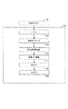
図1と図2は、構成可能な並直列変換器の概念を組み込んだ画像処理システム100を描いている。該画像処理システム100は、受信したビデオ信号を圧縮するエンコーダ104を備える。圧縮された信号は伝送チャネルまたは物理媒体108を使用して送信され、デコーダ112によって受信される。デコーダ112は受信された符号化済みのデータを、次に示されてよい画像サンプルに復号する。
FIGS. 1 and 2 depict an
一般的には、1つの画像は処理のためにピクセルの複数のブロックに分割される。カラー信号は、Yがルミナンス、つまり輝度成分であり、C1とC2がクロミナンス、つまりカラー成分であるRGB/YC1C2変換器116を使用してRGB空間からYC1C2空間に変換されてよい。目の色に対する低い空間感度のため、多くのシステムは水平方向と垂直方向で4という係数でC1成分とC2成分を二段抽出する(sub−sample)。しかしながら、二段抽出は不必要である。4:4:4フォーマットとして知られている完全解像度画像は、「デジタル映画」をカバーすると呼ばれている用途などのいくつかの用途では非常に有効であるか、または必要であるかのどちらかである可能性がある。2つの考えられるYC1C2表現はYIQ表現とYUV表現であり、両方とも技術では周知である。YCbCrとして知られているYUV表現の変形物を利用することも可能である。これは、さらに奇数成分と偶数成分に分割されてよい。したがって、ある実施形態では、表現Y偶数、Y奇数、Cb偶数、Cb奇数、Cr偶数、Cr奇数が使用される。 In general, an image is divided into blocks of pixels for processing. The color signal is converted from RGB space to YC 1 C 2 space using an RGB / YC 1 C 2 converter 116 where Y is the luminance, ie luminance component, and C 1 and C 2 are the chrominance, ie color components. May be. Because of the low spatial sensitivity to eye color, many systems sub-sample the C1 and C2 components with a factor of 4 in the horizontal and vertical directions. However, two-stage extraction is unnecessary. Full resolution images, known as 4: 4: 4 format, are either very useful or necessary for some applications, such as those that are called to cover "digital movies" There is a possibility. The two possible YC 1 C 2 representations are the YIQ representation and the YUV representation, both of which are well known in the art. A variant of the YUV representation known as YCbCr can also be used. This may be further divided into odd and even components. Thus, in some embodiments, the expressions Y even, Y odd, Cb even, Cb odd, Cr even, Cr odd are used.
好適実施形態において、偶数と奇数のY成分、Cb成分及びCr成分のそれぞれは二段抽出を行わずに処理される。したがって、ピクセルの16×16ブロックの6個の成分のそれぞれの入力がエンコーダ104に提供される。説明の目的で、Y偶数成分のためのエンコーダ104が描かれている。類似したエンコーダはY奇数成分、偶数Cb成分と奇数Cb成分、偶数Cr成分と奇数Cr成分に使用される。エンコーダ104は、ビデオ圧縮に備えてブロックサイズ割り当てを実行するブロックサイズ割り当て要素120を備える。ブロックサイズ割り当て要素120は、ブロックの中の画像の知覚による特性に基づき16×16ブロックのブロック分解を決定する。ブロックサイズ割り当ては、16×16ブロックの中の活動に応じて、それぞれの16×16ブロックを、4分木様式で8×8、4×4、及び2×2などのさらに小さなブロックに細分化する。ブロックサイズ割り当て要素120は、長さが1ビットと21ビットの間であるPQRデータと呼ばれる4分木データを生成する。したがって、ブロックサイズ割り当てが、16×16ブロックが分割されなければならないと判断すると、PQRデータのRビットが設定され、4個の分割された8×8ブロックに対応するQデータの4個の追加ビットが後に続く。ブロックサイズ割り当てが、8×8ブロックのどれかが細分化されなければならないと判断すると、8×8ブロックごとにPデータの4個の追加ビットが追加される。
In the preferred embodiment, each of the even and odd Y components, Cb components, and Cr components is processed without performing a two-stage extraction. Accordingly, an input of each of the six components of the 16 × 16 block of pixels is provided to the encoder 104. For illustrative purposes, an encoder 104 for the Y even component is depicted. Similar encoders are used for Y odd components, even Cb components and odd Cb components, even Cr components and odd Cr components. The encoder 104 includes a block
ここで図3を参照すると、ブロックサイズ割り当て要素120の演算の詳細を示すフロー図が示されている。ブロックの平方偏差は、ブロックを細分化するという決定における測定基準として使用される。ステップ102で開始し、ピクセルの16×16ブロックが読み取られる。ステップ204では、16×16ブロックの平方偏差v16が計算される。平方偏差は、以下のように計算され、
式中、N=16であり、xijはN×Nブロックの中のi番目の行、j番目の列の中のピクセルである。ステップ206では、ブロックの平均値が2個の所定の値の間にある場合、最初に平方偏差閾値T16が修正され、新しい閾値T’16を提供し、次にブロック平方偏差が新しい閾値T’16と比較される。
Where N = 16 and x ij is the pixel in the i th row and j th column in the N × N block. In
平方偏差v16が閾値T16以下の場合には、ステップ208で16×16ブロックの開始アドレスが一時記憶装置に書き込まれ、PQRデータのRビットが0に設定され、16×16ブロックが細分化されていないことを示す。それからアルゴリズムは、次のピクセルの16×16のブロックを読み取る。平方偏差v16が閾値T16より大きい場合には、ステップ210で、PQRデータのRビットが1に設定され、16×16ブロックが4個の8×8ブロックに細分化されなければならないことを示す。
If the square deviation v16 is less than or equal to the threshold T16, the start address of the 16 × 16 block is written to the temporary storage device in
4個の8×8ブロック、i=1:4は、ステップ212に図示されるように、追加細分化のために連続して考えられる。8×8ブロックごとに、ステップ214で平方偏差v8iが計算される。ステップ216では、ブロックの平均値が2個の所定の値の間にある場合、最初に平方偏差閾値T8が修正され、新しい閾値T’8を提供し、次にブロック平方偏差がこの新しい閾値に比較される。
Four 8 × 8 blocks, i = 1: 4, are considered sequentially for additional subdivision, as illustrated in
平方偏差v8iが閾値T8以下の場合には、ステップ218で8×8ブロックの開始アドレスが一時記憶に書き込まれ、対応するQビット、Qiが0に設定される。それから、次の8×8ブロックが処理される。平方偏差v8iが閾値T8より大きい場合には、ステップ220で、対応するQビットQiが1に設定され、8×8ブロックが4個の4×4ブロックに細分化されなければならないことを示す。
If the square deviation v8 i is less than or equal to the threshold T8, the start address of the 8 × 8 block is written to the temporary storage in
4個の4×4ブロック、ji=1:4は、ステップ222に図示されるように、追加細分化のために連続して考えられる。4×4ブロックごとに、ステップ24で平方偏差v4ijが計算される。ステップ226では、ブロックの平均値が2個の所定の値の間にある場合、最初に平方偏差閾値T4が修正され、新しい閾値T’4を提供し、次にブロック平方偏差がこの新しい閾値に比較される。
Four 4 × 4 blocks, j i = 1: 4, are considered sequentially for additional subdivision, as illustrated in
平方偏差v4ijが閾値T4以下の場合には、ステップ228で4×4ブロックのアドレスが書き込まれ、対応するPビットPijが0に設定される。それから次の4×4ブロックが処理される。平方偏差v4ijが閾値T4より大きい場合には、ステップ230で対応するPビットPijが一に設定され、4×4ブロックが2×2ブロックに細分化されなければならないことを示す。さらに、4個の2×2ブロックのアドレスが一時記憶装置に書き込まれる。
If the square deviation v4 ij is less than or equal to the threshold T4, the address of the 4 × 4 block is written in
閾値T16、T8及びT4は所定の定数であってよい。これは厳しい決断として知られている。代わりに、適応的意思決定または軟判定が実現されてよい。例えば、軟判定は、Nが8、4または2である場合に2N×2Nブロックの平均ピクセル値に応じて平方偏差のための閾値を変える。このようにして平均ピクセル値の関数は閾値として使用されてよい。 The threshold values T16, T8, and T4 may be predetermined constants. This is known as a tough decision. Instead, adaptive decision making or soft decisions may be realized. For example, the soft decision changes the threshold for the square deviation according to the average pixel value of 2N × 2N blocks when N is 8, 4 or 2. In this way, a function of the average pixel value may be used as a threshold value.
説明のために、以下の例を考える。Y成分の所定の平均偏差閾値が、それぞれ16×16、8×8、4×4のブロックの場合50、1100及び800であるとする。言い換えると、T16=50、T8=100、及びT4=880である。平均値の範囲を80と100とする。16×16ブロックの計算された平方偏差が60であると仮定する。60はT16より大きく、平均値90は80と100の間であるため、16×16ブロックは4個の8×8サブブロックに細分化される。8×8ブロックの計算された平方偏差が1180、935、980及び1210であると仮定する。8×8ブロックの内の2つはT8を上回る平方偏差を有しているため、これらの2個のブロックはさらに細分化され、合計8個の4×4サブブロックを生成する。最後に、8個の4×4ブロックの平方偏差が620、630、670、610、590、525、930及び690であり、対応する平均値が90、120、110、115であると仮定する。最初の4×4ブロックの平均値が範囲(80、100)に該当するため、その閾値は880未満であるT’4=200に引き下げられる。したがって、7番目の4×4ブロックだけではなくこの4×4ブロックも細分化される。 For illustration purposes, consider the following example. Assume that the predetermined average deviation threshold values of the Y component are 50, 1100, and 800 for blocks of 16 × 16, 8 × 8, and 4 × 4, respectively. In other words, T16 = 50, T8 = 100, and T4 = 880. The average value range is 80 and 100. Assume that the calculated square deviation of a 16 × 16 block is 60. Since 60 is larger than T16 and the average value 90 is between 80 and 100, the 16 × 16 block is subdivided into four 8 × 8 sub-blocks. Assume that the calculated square deviations of 8 × 8 blocks are 1180, 935, 980 and 1210. Since two of the 8 × 8 blocks have a square deviation greater than T8, these two blocks are further subdivided to produce a total of 8 4 × 4 sub-blocks. Finally, assume that the square deviations of the 8 4 × 4 blocks are 620, 630, 670, 610, 590, 525, 930 and 690, and the corresponding mean values are 90, 120, 110, 115. Since the average value of the first 4 × 4 block falls within the range (80, 100), the threshold is lowered to T′4 = 200, which is less than 880. Therefore, not only the seventh 4 × 4 block but also this 4 × 4 block is subdivided.
ルミナンス成分Y奇数とカラー成分Cb−even、Cb−odd、Cr−even及びCr−oddのブロックサイズを割り当てるために類似する手順が使用されることに注意する。カラー成分は水平に、垂直に、あるいは両方で間引きされ(decimated)てよい。 Note that a similar procedure is used to assign block sizes for the luminance component Y odd and the color components C b-even , C b-odd , C r-even and C r-odd . The color components may be decimated horizontally, vertically, or both.
さらに、ブロックサイズ割り当ては、最大のブロック(この例では16×16)が最初に評価される下降型アプローチと説明されてきたが、ボトムアップアプローチを代わりに使用してよいことに注意する。ボトムアップアプローチは最初に最小のブロック(本発明では2×2)を評価するだろう。 Furthermore, although block size allocation has been described as a descending approach where the largest block (16 × 16 in this example) is evaluated first, note that a bottom-up approach may be used instead. The bottom-up approach will first evaluate the smallest block (2 × 2 in the present invention).
図1を参照し直すと、選択されたブロックのアドレスとともにPQRデータがDCT要素124に提供される。DCT要素124は選択されたブロックで適切なサイズの離散コサイン変換を実行するためにPQRデータを使用する。選択されたブロックだけがDCT処理を受ける必要がある。
Referring back to FIG. 1, PQR data is provided to the
画像処理システム100は、DCTのDC係数の間の冗長性を削減するためにDQT要素128も備える。DC係数には各DCTブロックの左上角で遭遇する。一般的には、DC係数はAC係数に比較して大きい。サイズの不一致により、効率的な可変長コーダを設計するのが困難になる。したがって、DC係数の間で冗長性を削減することが有利である。
The
DCT要素128は、一度に2×2取られるDC係数で2−D DCTを実行する。4×4ブロックの中の2×2ブロックで開始し、2−D DCTが4つのDC係数で実行される。この2×2 DCTが4つのDC係数の微分4分木変換、つまりDQTと呼ばれる。次に8×8ブロックの中の3つの隣接するDC係数とともにDQTのDC係数が次のレベルのDQTを計算するために使用される。最後に、1つの16×16ブロックの中の4個の8×8ブロックのDC係数がDQTを計算するために使用される。このようにして、1つの16×16のブロックでは、1個の真のDC係数があり、残りはDCTとDQTに対応するAC係数である。
The
変換係数(DCTとDQTの両方)は、量子化のために量子化装置に提供される。好適実施形態においては、DCT係数は周波数加重マスク(frequency weighting masks)(FWM)と量子化スケールファクタを使用して量子化される。FWMは入力DCT係数のブロックと同じ寸法の周波数重みのテーブルである。周波数重みは様々な重みを様々なDCT係数に適用する。重みは、人間の視覚系または光学系がより敏感である周波数コンテンツを有する入力サンプルを強調し、視覚系または光学系がより敏感ではない周波数コンテンツを有するサンプルの重視をやめるように作られている。重みは、視距離などのファクタに基づいて設計されてもよい。 The transform coefficients (both DCT and DQT) are provided to the quantizer for quantization. In the preferred embodiment, the DCT coefficients are quantized using a frequency weighting mask (FWM) and a quantization scale factor. FWM is a table of frequency weights having the same dimensions as the block of input DCT coefficients. Frequency weights apply different weights to different DCT coefficients. The weights are designed to emphasize input samples that have frequency content that is more sensitive to the human visual system or optics, and to stop emphasizing samples that have frequency content that is less sensitive to the visual system or optics. . The weight may be designed based on factors such as viewing distance.
重みは実験によって得られるデータに基づいて選択される。8×8DCT係数のための加重マスクを設計する方法は、参照してここに組み込まれるISO/IEC JTC1 CD 10981「連続階調静止画像のデジタル圧縮及び符号化−第1部:要件及び指針(Digital compression and encoding of continuous-tone still images - part 1: Requirements and guidelines)」、国際標準化機構、1994に開示されている。一般的には、1つはルミナンス成分のため、1つはクロミナンス成分のための2つのFWMが設計される。ブロックサイズ2×2、4×4のFWMテーブルは間引き(decimation)によって取得され、16×16は8×8ブロックのための間引きの補間によって取得される。スケールファクタは量子化された係数の品質及びビット転送速度を制御する。
The weight is selected based on data obtained through experiments. The method for designing weighted masks for 8 × 8 DCT coefficients is described in ISO / IEC JTC1 CD 10981 “Digital compression and encoding of continuous tone still images—part 1: requirements and guidelines (Digital). compression and encoding of continuous-tone still images-part 1: Requirements and guidelines) ", International Organization for Standardization, 1994. In general, two FWMs are designed, one for the luminance component and one for the chrominance component. The FWM table of
したがって、各DCT係数は、以下の関係に従って量子化され、
式中、DCT(i,j)は入力DCT係数であり、fwm(i,j)は周波数加重マスクであり、qはスケールファクタであり、DCTq(i,j)は量子化された係数である。DCT係数の符号によっては、角括弧の内側の第1項が切り上げられる、または切り下げられることに注意する。DQT係数は適切な加重マスクを使用しても量子化される。ただし、複数のテーブルまたはマスクを使用することができ、Y成分、Cb成分及びCr成分のそれぞれに適用できる。 Where DCT (i, j) is the input DCT coefficient, fwm (i, j) is the frequency weighting mask, q is the scale factor, and DCTq (i, j) is the quantized coefficient. . Note that depending on the sign of the DCT coefficient, the first term inside the square brackets is rounded up or down. DQT coefficients are also quantized using an appropriate weighting mask. However, a plurality of tables or masks can be used, and can be applied to each of the Y component, the Cb component, and the Cr component.
次にピクセルデータのブロック及び周波数加重マスクは、量子化装置130、つまりスケールファクタ要素によって倍数をかけられる。DCT係数の量子化は、それらの大多数を、圧縮を生じさせるゼロに削減する。好適実施形態においては、平均ビット転送速度に対応する32のスケールファクタがある。MPEG2などの他の圧縮方法とは異なり、平均ビット転送速度は、ターゲットビット転送速度とバッファステータスの代わりに処理された画像の品質に基づいて制御される。
The block of pixel data and the frequency weighted mask are then multiplied by a
さらに圧縮を強化するために、量子化された係数が走査並直列変換器134に提供される。該並直列変換器134は量子化された係数のブロックを走査し、量子化された係数の直列化されたストリームを生成する。ジグザグ走査、列走査、または行走査が利用されてよい。ジグザグ以外の多くの異なったジグザグ走査パターンも選んでよい。好適技法はジグザグ走査に8×8ブロックサイズを利用する。量子化された係数のジグザグ走査はゼロ値の大きなランに遭遇する確率を高める。このゼロランは本質的に減少する確率を有し、ハフマンコードを使用して効率的に符号化されてよい。
To further enhance the compression, the quantized coefficients are provided to the scan to
直列化され、量子化された係数のストリームは可変長コーダ138に提供される。ランレングスコーダは、非ゼロ係数から、ゼロの間の量子化された係数を分離し、図6に関して詳細に説明される。ある実施形態においては、Golomb−Riceコーディングが活用される。Golomb−Rice符号化は、指数分布のある非負整数をコーディングする際に効率的である。ゴロンブコードを使用することは、指数分布された変数にさらに短い長さの符号を提供するという点で圧縮により最適である。
The stream of serialized and quantized coefficients is provided to
ランレングスをゴロンブ符号化する際には、ゴロンブコードは非負整数mでパラメータ化される。例えば、パラメータmを考慮すると、正の整数nのゴロンブコーディングは、剰余が2[log2m]−m未満である場合には長さ[log2m]ビットであり、それ以外の場合長さ[log2m]ビットである修正されたバイナリコードによって表現される剰余が後に続く単項コードの中のn/mという商によって表現される。Golomb−Riceコーディングは、パラメータmがm=2kとして表現されるGolombコーディングの特殊なケースである。このようなケースでは、n/mの商は整数nのバイナリ表現をkビット分右にシフトすることによって取得され、n/mの剰余はnの最小kビットで表現される。このようにして、Glomb−Riceコードは2つの連結である。Golomb−Riceコーディングは、以下によって示されるように、正の整数と負の整数の両方を2辺の幾何(指数)文法で符号化するために使用できる。
(1)では、αはxの確率の減少を特徴付けるパラメータであり、cは正規化定数である。pα(x)は単調であるため、整数値のシーケンスが以下を満たす必要があることが分かる。
![]()
![]()
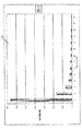
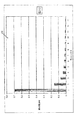
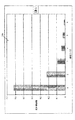
図4a、図4b、図4c、及び図5a、図5b、図5cに描かれているように、量子化されたDCT係数行列の中のゼロランと振幅の両方とも指数分布を有する。これらの図に描かれている分布は実像からのデータに基づいている。図4aはゼロランレングス対相対周波数のY成分分布400を描いている。同様に、図4bと図4cは、それぞれゼロランレングス対相対周波数410と420のCb成分とCr成分の分布を描いている。図5aは振幅サイズ対相対周波数のY成分分布500を描いている。同様に、図5bと図5cはそれぞれ振幅サイズ対相対周波数510と520のCb成分とCr成分の分布を描いている。図5a、図5b及び図5cでは、プロットがDCT係数のサイズの分布を表現していることに注意する。各サイズは係数値の範囲を表現している。例えば、4というサイズ値は範囲{−15,−14,…−8,8,…14,15}、合計16個の値を有している。同様に10というサイズ値は、範囲{−1023,−1022,…,−512,512,…1022,1023}、合計1024の値を有している。図4a、図4b、図4c、図5a、図5b、及び図5cから、ランレングスと振幅サイズの両方ともが指数分布を有していることが分かる。振幅の実際の分布は以下の等式(3)に適合するように示すことができる。
(3)では、Xk,lは、それぞれ垂直面と水平面の周波数kとlに対応するDCT係数、及び平均
平方絵偏差
を表している。したがって、説明されたようにGolomb−Riceコーディングを使用することはDCTでデータを処理する上でより最適である。 Represents. Therefore, using Golomb-Rice coding as described is more optimal for processing data with DCT.
以下は画像データの圧縮に関して説明されているが、実施形態は音声データを圧縮する実施形態に等しく適用できる。画像データを圧縮する際には、画像信号またはビデオ信号は、例えば、線形または対数符号化ピクセル値を含むRGB成分またはYIQ成分、あるいはYUV成分あるいはY成分、Cb成分、Cr成分であってよい。 Although the following is described with respect to compression of image data, the embodiments are equally applicable to embodiments that compress audio data. When compressing image data, the image signal or video signal may be, for example, an RGB component or YIQ component including a linear or logarithmically encoded pixel value, or a YUV component or Y component, a Cb component, or a Cr component.
図6はゼロ係数及び非ゼロ係数を符号化するプロセス600を描いている。DCT行列が走査されるにつれて、ゼロ係数と非ゼロ係数は別々に処理され、分離される604。ゼロデータの場合、ゼロランの長さが求められる608。ランレングスは正の整数であることに注意する。例えば、ランレングスがnであることが判明すると、ゴロンブパラメータmが求められる612。ある実施形態においては、ゴロンブパラメータはランレングスの関数として求められる。別の実施形態においては、ゴロンブパラメータ(m)は以下の等式(4)で求められる。
任意に、ランレングスの長さと関連するゴロンブパラメータはカウンタまたはレジスタによってカウントされる616。ゼロのランレングスnを符号化するためには、商が符号化される620。ある実施形態においては、商はゼロのランレングスとゴロンブパラメータの関数として求められる。別の実施形態においては、商(Q)は以下の等式(5)によって求められる。
ある実施形態においては、商QはQ+1ビットを必要とする単項コードで符号化される。次に剰余が符号化される624。ある実施形態においては、剰余はランレングスと商の関数として符号化される。別の実施形態においては、剰余(R)は以下の等式(6)を使用して求められる。
ある実施形態においては、剰余Rはmビットバイナリコードで符号化される。商Qと剰余Rが求められた後、QとRのコードが連結され628、ゼロのランレングスnの全体的なコードを表す。 In some embodiments, the remainder R is encoded with an m-bit binary code. After the quotient Q and the remainder R are determined, the codes of Q and R are concatenated 628 to represent the overall code of zero run length n.
非ゼロ係数もGolomb−Riceを使用して符号化される。係数振幅は正または負である場合があるため、符号ビットを使用し、指定された振幅の絶対値を符号化することが必要である。非ゼロ係数の振幅がxであることを考慮すると、振幅は振幅と符号の絶対値の関数として表現されてよい。したがって、振幅は以下の等式(7)を使用してyとして表現されてよい。
したがって、非ゼロ係数の値は任意にカウンタまたはレジスタによってカウントされる632。次に、振幅がゼロ以上であるのかが判断される636。ゼロ以上である場合、値は指定された値の2倍として符号化される640。以上ではない場合、値は絶対値の2倍未満の値として符号化される644。他のマッピング方式も利用されてよいことが考慮される。カギは、値の符号を区別するための余分なビットが必要とされないという点である。 Accordingly, the value of the non-zero coefficient is optionally counted 632 by a counter or register. Next, it is determined 636 whether the amplitude is greater than or equal to zero. If it is greater than or equal to zero, the value is encoded 640 as twice the specified value. Otherwise, the value is encoded 644 as a value less than twice the absolute value. It is contemplated that other mapping schemes may also be utilized. The key is that no extra bits are required to distinguish the sign of the value.
振幅を等式(7)によって表現されるように符号化すると、偶数の整数であるxの正の値が生じ、負の値は奇数の整数になる。さらに、このマッピングは(2)におけるようにxの確率割り当てを維持する。等式(7)で描かれているような符号化の優位点によって、人は符号ビットを使用して正の数と負の数を表現するのを回避できるようになる。マッピングが行われた後、yはゼロランについて行われたのと同様に符号化される。該手順は、すべての係数が現在のブロックの中で走査されるまで続行される。 Encoding the amplitude as represented by equation (7) yields a positive value for x, which is an even integer, and a negative value becomes an odd integer. In addition, this mapping maintains a probability allocation of x as in (2). The coding advantage as depicted in equation (7) allows one to avoid using the sign bit to represent positive and negative numbers. After the mapping is done, y is encoded as it was done for the zero run. The procedure continues until all coefficients have been scanned in the current block.
本発明の実施形態は係数の値とランレングスを等式(1)〜(7)の関数として求めるが、正確な等式(1)〜(7)が使用される必要はないことを認識することは重要である。画像及び音声データのより効率的な圧縮を可能にするのは、Golomb−Rice符号化及びDCT係数の指数分布を利用することである。 Embodiments of the present invention determine coefficient values and run lengths as a function of equations (1)-(7), but recognize that exact equations (1)-(7) need not be used. That is important. Enabling more efficient compression of image and audio data is to use Golomb-Rice coding and the exponential distribution of DCT coefficients.
符号化の後のゼロランは非ゼロ振幅から区別できないため、第1のゼロランの発生を記すために固定長の特殊な接頭辞コードを使用することが必要になる場合がある。非ゼロ振幅に遭遇した後にブロックの中のすべてのゼロに遭遇することは普通である。このようなケースでは、Golomb−Riceコードよりむしろブロック終結(EOB)コードを参照するコードを使用する方がより効率的である可能性がある。再び任意に、EOBコードは特殊固定長コードである。 Since zero runs after encoding are indistinguishable from non-zero amplitudes, it may be necessary to use a fixed length special prefix code to mark the occurrence of the first zero run. It is common to encounter all zeros in a block after encountering a non-zero amplitude. In such cases, it may be more efficient to use a code that references an end of block (EOB) code rather than a Golomb-Rice code. Again optionally, the EOB code is a special fixed length code.
等式(1)または(3)に従って、DCT係数行列の中の振幅またはランレングスの確率分布はαまたはλによってパラメータ化される。特定のDCT係数ブロックが生じるコンテキストにおいて、コーディング効率は高められる可能性があるという意味合いである。その結果、所定の量を符号化するためのGolomb−Riceパラメータが使用されてよい。ある実施形態においては、カウンタまたはレジスタはそれぞれの累積値及びこのような値が発生する対応する回数を計算するためにランレングスと振幅サイズごとに使用される。例えば、累積値及び蓄積される要素数を記憶するためのレジスタがそれぞれRrlとNrlである場合、以下の等式(6)がランレングスを符号化するためにRice−Golombパラメータとして使用されてよい。
類似した手順が振幅について使用されてよい。 A similar procedure may be used for amplitude.
図1を参照し直すと、エンコーダ104によって生成される圧縮された画像信号は一時的にバッファ142を使用して記憶され、次に伝送チャネル108を使用してデコーダ112に送信されてよい。伝送チャネル108は、磁気デバイスまたは光記憶デバイス、あるいはワイヤレス伝達プロセスまたは装置、あるいはワイヤレス伝達プロセスまたは装置などの物理的な媒体であってよい。ブロックサイズ割り当て情報を含むPQRデータもデコーダ112に提供される(図2)。デコーダ112はバッファ164及びランレングス値及び非ゼロ値を復号する可変長デコーダ168を備える。可変長デコーダ168は、図6に説明される方法と類似するが反対の方法で動作する。
Referring back to FIG. 1, the compressed image signal generated by encoder 104 may be temporarily stored using
可変長デコーダ168の出力は、利用される走査方式に従って係数を並べる逆並直列変換器172に提供される。例えば、ジグザグ走査、垂直走査、及び水平走査の混合物が使用される場合、逆並直列変換器172は利用される走査の種別を知っていることで係数を適切に並べ替えるだろう。逆並直列変換器172はPQRデータを受信し、係数の1つの複合係数ブロックへの適切な配列を補助する。
The output of the variable length decoder 168 is provided to an anti-parallel
該複合ブロックは、量子化装置スケールファクタ及び周波数加重マスクの使用のための処理を元に戻すために、逆量子化装置174に提供される。
The composite block is provided to the
係数ブロックは次に、微分4分木変換が適用された場合には、IDCT要素190が後に続くIDQT要素186に提供される。それ以外の場合、係数ブロックはIDCT要素190に直接提供される。IDQT要素186とIDCT要素190は係数を逆変換し、ピクセルデータのブロックを生成する。該ピクセルデータは次に補間され、RGB形式に変換され、将来の表示のために記憶されなければならない。
The coefficient block is then provided to an
図7は、Golomb−Rice符号化700用の装置を描いている。図7の装置は、好ましくは図6に関して説明されるようなプロセスを実現する。意思決定装置(determiner)704はランレングス(n)とゴロンブパラメータ(m)を決定する。任意に、カウンタまたはレジスタ708が、それぞれの累積値及びこのような値が発生する対応する回数を計算するために、各ランレングスと振幅サイズ値ごとに使用される。エンコーダ712はランレングスとゴロンブパラメータの関数として商(Q)を符号化する。また、エンコーダ712はランレングス、ゴロンブパラメータ及び商の関数として剰余(R)を符号化する。代替実施形態においては、エンコーダ712は非ゼロデータ値と非ゼロデータ値の符号の関数として非ゼロデータも符号化する。連結装置(concatenator)716は、Q値とR値を連結するために使用される。
FIG. 7 depicts an apparatus for Golomb-
例として、ここに開示されている実施形態に関連して説明された多様な例示的な論理ブロック、フローチャート及びステップが、特定用途向け集積回路(ASIC)、プログラマブルロジックデバイス、離散ゲートまたはトランジスタロジック、例えばレジスタとFIFOなどの離散ハードウェア構成要素、一式のファームウェア命令として実行するプロセッサ、任意の従来のプログラム可能ソフトウェア、及びプロセッサ、あるいはその組み合わせをもって、ハードウェアまたはソフトウェアの中で実現または実行されてよい。プロセッサは、有利にはマイクロプロセッサであってよいが、代替例ではプロセッサは任意の従来のプロセッサ、コントローラ、マイクロコントローラ、または状態機械であってよい。ソフトウェアはRAMメモリ、フラッシュメモリ、ROMメモリ、レジスタ、ハードディスク、取り外し可能ディスク、CD−ROM、DVD−ROM、または技術で既知である任意の他の形の記憶媒体に常駐する場合がある。 By way of example, the various exemplary logic blocks, flowcharts, and steps described in connection with the embodiments disclosed herein can be found in application specific integrated circuits (ASICs), programmable logic devices, discrete gate or transistor logic, May be implemented or executed in hardware or software, with discrete hardware components such as registers and FIFOs, a processor executing as a set of firmware instructions, any conventional programmable software, and processor, or combinations thereof . The processor may advantageously be a microprocessor, but in the alternative, the processor may be any conventional processor, controller, microcontroller, or state machine. The software may reside in RAM memory, flash memory, ROM memory, registers, hard disks, removable disks, CD-ROMs, DVD-ROMs, or any other form of storage medium known in the art.
好適実施形態の前記説明は、当業者が本発明を作るあるいは使用できるようにするために提供される。これらの実施形態に対する多様な変型は、容易に当業者に明らかになり、ここに定義される一般的な原則は本発明の機能を使用しなくとも他の実施形態に適用されてよい。したがって、本発明はここに示されている実施形態に制限されるのではなく、ここに開示されている原則及び新規特徴と一貫する最も広い範囲を与えられることを目的とする。 The previous description of the preferred embodiments is provided to enable any person skilled in the art to make or use the present invention. Various modifications to these embodiments will be readily apparent to those skilled in the art, and the general principles defined herein may be applied to other embodiments without using the features of the present invention. Accordingly, the present invention is not intended to be limited to the embodiments shown herein but is to be accorded the widest scope consistent with the principles and novel features disclosed herein.
本発明の他の特徴及び優位点は以下のクレームに述べられる。 Other features and advantages of the invention are set forth in the following claims.
Claims (14)
ゼロデータの場合:
ゼロランレングス(n)を決定する;
ゼロランレングスの関数としてゴロンブ(Golomb)パラメータを決定する、ゴロンブパラメータ(m)は式m=[log2n]を用いて決定される;
前記ゼロランレングスおよび前記ゴロンブパラメータの関数として商(Q)を符号化する;
前記ゼロランレングス、前記ゴロンブパラメータ、および前記商の関数として剰余(R)を符号化する;
および
前記符号化された商および符号化された剰余を連結する;
および非ゼロデータの場合:
前記ノンゼロデータおよび前記ノンゼロデータの符号の関数として前記ノンゼロデータを符号化する。A method for encoding quantized frequency displayed data comprising zero data and non-zero data comprising:
For zero data:
Determine zero run length (n);
Determine the Golomb parameter as a function of zero run length, the Golomb parameter (m) is determined using the equation m = [log2n];
Encoding the quotient (Q) as a function of the zero run length and the Golomb parameter;
Encoding the remainder (R) as a function of the zero run length, the Golomb parameter, and the quotient;
And concatenating the encoded quotient and encoded remainder;
And for non-zero data:
The non-zero data is encoded as a function of the non-zero data and the sign of the non-zero data.
ゼロデータの場合;
ゼロランレングス(n)を決定する手段;
前記ゼロランレングスの関数としてゴロンブ(Golomb)パラメータ(m)を決定する手段、前記ゴロンブパラメータ(m)は、式m=[log2n]を用いて決定される;
前記ゼロランレングスおよび前記ゴロンブパラメータの関数として商(Q)を符号化する手段;
前記ゼロランレングス、前記ゴロンブパラメータ、および前記商の関数として剰余(R)を符号化する手段;
および
前記符号化された商と符号化された剰余を連結する手段;
および非ゼロデータの場合:
前記非ゼロデータの値および前記非ゼロデータの符号の関数として前記非ゼロデータを符号化する手段。An apparatus for encoding quantized frequency-represented data comprising zero data and non-zero data comprising:
For zero data;
Means for determining zero run length (n);
Means for determining a Golomb parameter (m) as a function of the zero run length, the Golomb parameter (m) being determined using the equation m = [log2n];
Means for encoding a quotient (Q) as a function of the zero run length and the Golomb parameter;
Means for encoding a remainder (R) as a function of the zero run length, the Golomb parameter, and the quotient;
And means for concatenating the encoded quotient with the encoded remainder;
And for non-zero data:
Means for encoding the non-zero data as a function of the value of the non-zero data and the sign of the non-zero data;
を用いてyの値であるように決定される、請求項5に記載の装置。The encoding of the non-zero data is given by the equation
6. The apparatus of claim 5, wherein the apparatus is determined to be the value of y using.
ゼロデータの場合;
ゼロランレングス(n)を決定するように構成された第1決定器;
前記ゼロランレングスの関数としてゴロンブ(Golomb)パラメータ(m)を決定するように構成された第2決定器、前記ゴロンブパラメータは、式m=[log2n]を用いて決定される;
前記ランレングスおよび前記ゴロンブパラメータの関数として商(Q)を符号化するように構成され、および前記ゼロランレングス、前記ゴロンブパラメータおよび前記商の関数として剰余(R)を符号化するように構成され、非ゼロデータの場合、前記非ゼロデータと前記非ゼロデータの符号の値の関数として前記非ゼロデータを符号化するエンコーダ;
および
前記符号化された商および符号化された剰余を連結するように構成された連結器。An apparatus for encoding quantized frequency-represented data comprising zero data and non-zero data comprising:
For zero data;
A first determiner configured to determine a zero run length (n);
A second determinator configured to determine a Golomb parameter (m) as a function of the zero run length, the Golomb parameter is determined using the equation m = [log2n];
Configured to encode a quotient (Q) as a function of the run length and the Golomb parameter, and to encode a remainder (R) as a function of the zero run length, the Golomb parameter and the quotient. An encoder configured to encode the non-zero data as a function of a value of a sign of the non-zero data and the non-zero data in the case of non-zero data;
And a coupler configured to concatenate the encoded quotient and the encoded remainder.
Applications Claiming Priority (2)
| Application Number | Priority Date | Filing Date | Title |
|---|---|---|---|
| US09/895,618 US6735254B2 (en) | 2001-06-29 | 2001-06-29 | DCT compression using Golomb-Rice coding |
| PCT/US2002/019407 WO2003003738A2 (en) | 2001-06-29 | 2002-06-17 | Dct compression using golomb-rice coding |
Publications (3)
| Publication Number | Publication Date |
|---|---|
| JP2004531995A JP2004531995A (en) | 2004-10-14 |
| JP2004531995A5 JP2004531995A5 (en) | 2006-01-05 |
| JP4113114B2 true JP4113114B2 (en) | 2008-07-09 |
Family
ID=25404771
Family Applications (1)
| Application Number | Title | Priority Date | Filing Date |
|---|---|---|---|
| JP2003509776A Expired - Lifetime JP4113114B2 (en) | 2001-06-29 | 2002-06-17 | DCT compression using GOLOMB-RICE coding |
Country Status (11)
| Country | Link |
|---|---|
| US (5) | US6735254B2 (en) |
| EP (2) | EP1407603B1 (en) |
| JP (1) | JP4113114B2 (en) |
| KR (2) | KR100926381B1 (en) |
| CN (3) | CN100518326C (en) |
| BR (1) | BR0210582A (en) |
| CA (1) | CA2451604C (en) |
| HK (2) | HK1095003A1 (en) |
| MX (1) | MXPA03012053A (en) |
| SG (2) | SG170613A1 (en) |
| WO (1) | WO2003003738A2 (en) |
Cited By (1)
| Publication number | Priority date | Publication date | Assignee | Title |
|---|---|---|---|---|
| JPH0648928U (en) * | 1992-12-09 | 1994-07-05 | アイワ株式会社 | Molding equipment |
Families Citing this family (40)
| Publication number | Priority date | Publication date | Assignee | Title |
|---|---|---|---|---|
| US6735254B2 (en) * | 2001-06-29 | 2004-05-11 | Qualcomm, Inc. | DCT compression using Golomb-Rice coding |
| US7251372B2 (en) * | 2004-01-14 | 2007-07-31 | Nec Solutions (America) Inc. | Method and system for compressing digitized fingerprint images by a uniform degree of compression |
| KR100561869B1 (en) * | 2004-03-10 | 2006-03-17 | 삼성전자주식회사 | Lossless audio decoding/encoding method and apparatus |
| KR20060051157A (en) * | 2004-10-29 | 2006-05-19 | 마이크로소프트 코포레이션 | Lossless adaptive encoding and decoding of integer data |
| US7015837B1 (en) * | 2004-10-29 | 2006-03-21 | Microsoft Corporation | Lossless adaptive encoding and decoding of integer data |
| US6987468B1 (en) * | 2004-10-29 | 2006-01-17 | Microsoft Corporation | Lossless adaptive encoding and decoding of integer data |
| US7580585B2 (en) | 2004-10-29 | 2009-08-25 | Microsoft Corporation | Lossless adaptive Golomb/Rice encoding and decoding of integer data using backward-adaptive rules |
| KR100586026B1 (en) * | 2005-03-25 | 2006-06-02 | 한국전자통신연구원 | Apparatus and method for encoding or/and decoding digital hologram |
| KR101088375B1 (en) * | 2005-07-21 | 2011-12-01 | 삼성전자주식회사 | apparatus and method for adaptive variable block-size transform and the appartus and the method for video encoding/decoding thereof. |
| JP4732203B2 (en) * | 2006-03-17 | 2011-07-27 | キヤノン株式会社 | Image encoding apparatus, decoding apparatus, control method therefor, computer program, and computer-readable storage medium |
| WO2008000292A1 (en) * | 2006-06-30 | 2008-01-03 | Telecom Italia S.P.A. | Method, apparatus and system for robust video transmission |
| US8116378B2 (en) * | 2006-12-15 | 2012-02-14 | Arcsoft, Inc. | Variable length decoding method |
| WO2008093698A1 (en) * | 2007-01-31 | 2008-08-07 | Sony Corporation | Information processing device and method |
| KR101539240B1 (en) * | 2007-06-14 | 2015-07-30 | 삼성전자주식회사 | Method and apparatus for encoding and decoding image data |
| US20090238259A1 (en) * | 2008-03-19 | 2009-09-24 | Sung-Hung Yeh | Method of rate control for video frame compression and encoder thereof |
| US7733245B2 (en) * | 2008-06-25 | 2010-06-08 | Aclara Power-Line Systems Inc. | Compression scheme for interval data |
| EP2141815A1 (en) * | 2008-07-01 | 2010-01-06 | Deutsche Thomson OHG | Method for a hybrid Golomb-Elias gamma coding |
| US8576927B2 (en) * | 2008-10-10 | 2013-11-05 | Nippon Telegraph And Telephone Corporation | Encoding method, encoding device, decoding method, decoding device, program, and recording medium |
| US8761268B2 (en) * | 2009-04-06 | 2014-06-24 | Intel Corporation | Selective local adaptive wiener filter for video coding and decoding |
| CN101729900B (en) * | 2009-11-17 | 2014-03-26 | 北京中星微电子有限公司 | Quantification control method and quantification device for discrete cosine transform coefficient |
| JP5741076B2 (en) | 2010-12-09 | 2015-07-01 | ソニー株式会社 | Image processing apparatus and image processing method |
| JP5815853B2 (en) * | 2011-08-23 | 2015-11-17 | メディア テック シンガポール ピーティーイー.リミテッド | Method and system for transform block processing according to quantization matrix in video coding |
| EP2774360B1 (en) | 2011-11-04 | 2017-08-02 | Huawei Technologies Co., Ltd. | Differential pulse code modulation intra prediction for high efficiency video coding |
| KR20130050149A (en) | 2011-11-07 | 2013-05-15 | 오수미 | Method for generating prediction block in inter prediction mode |
| CN106851277B (en) | 2012-04-13 | 2021-05-07 | 佳能株式会社 | Method, apparatus and system for encoding and decoding a subset of transform units of video data |
| EP2840789B1 (en) | 2012-04-15 | 2018-09-12 | Samsung Electronics Co., Ltd. | Parameter update method for entropy decoding of conversion coefficient level, and entropy decoding device of conversion coefficient level using same |
| US10021419B2 (en) * | 2013-07-12 | 2018-07-10 | Qualcomm Incorported | Rice parameter initialization for coefficient level coding in video coding process |
| CN103731155A (en) * | 2013-12-31 | 2014-04-16 | 成都华日通讯技术有限公司 | Time domain compression method of radio-frequency spectrum signals |
| CA2880458A1 (en) | 2014-01-29 | 2015-07-29 | Ecole De Technologie Superieure | Method and system for rate-constrained search ordering |
| US10142636B2 (en) * | 2014-06-09 | 2018-11-27 | Sony Corporation | Communication system with coding mechanism and method of operation thereof |
| WO2016119046A1 (en) | 2015-01-29 | 2016-08-04 | Ecole De Technologie Superieure | Methods and systems for determining motion vectors in a motion estimation process of a video encoder |
| US10432972B2 (en) * | 2016-10-19 | 2019-10-01 | Google Llc | Guided offset correction for loop restoration in video coding |
| US10595033B2 (en) | 2017-02-15 | 2020-03-17 | Sony Corporation | Variable length coding of header data for image compression |
| US10950251B2 (en) * | 2018-03-05 | 2021-03-16 | Dts, Inc. | Coding of harmonic signals in transform-based audio codecs |
| DE102018122295A1 (en) * | 2018-09-12 | 2020-03-12 | Arnold & Richter Cine Technik Gmbh & Co. Betriebs Kg | Process for compressing image data |
| JP7213364B2 (en) * | 2018-10-31 | 2023-01-26 | ノキア テクノロジーズ オーユー | Coding of Spatial Audio Parameters and Determination of Corresponding Decoding |
| GB2582749A (en) * | 2019-03-28 | 2020-10-07 | Nokia Technologies Oy | Determination of the significance of spatial audio parameters and associated encoding |
| KR20210136476A (en) | 2020-05-07 | 2021-11-17 | 삼성전자주식회사 | Compressing device and method using parameters of a quad-tree method |
| CN113143284B (en) * | 2021-04-13 | 2022-10-21 | 浙江大学 | Electrocardiosignal compression method based on wavelet transformation and dual-mode prediction |
| CN117411947B (en) * | 2023-12-15 | 2024-02-23 | 安徽中科大国祯信息科技有限责任公司 | Cloud edge cooperation-based water service data rapid transmission method |
Family Cites Families (20)
| Publication number | Priority date | Publication date | Assignee | Title |
|---|---|---|---|---|
| US5036457A (en) | 1987-09-24 | 1991-07-30 | Nucleus International Corporation | Bit string compressor with boolean operation processing capability |
| US5532694A (en) | 1989-01-13 | 1996-07-02 | Stac Electronics, Inc. | Data compression apparatus and method using matching string searching and Huffman encoding |
| US5021891A (en) | 1990-02-27 | 1991-06-04 | Qualcomm, Inc. | Adaptive block size image compression method and system |
| US5107345A (en) | 1990-02-27 | 1992-04-21 | Qualcomm Incorporated | Adaptive block size image compression method and system |
| US5079621A (en) * | 1990-06-29 | 1992-01-07 | Eastman Kodak Company | Dct transform compression, transmission and recovery of digital color using virtual filtering mechanism |
| ATE159396T1 (en) | 1991-06-04 | 1997-11-15 | Qualcomm Inc | SYSTEM FOR ADAPTIVE COMPRESSION OF THE BLOCK SIZES OF AN IMAGE |
| US5603012A (en) | 1992-06-30 | 1997-02-11 | Discovision Associates | Start code detector |
| US5379070A (en) * | 1992-10-02 | 1995-01-03 | Zoran Corporation | Parallel encoding/decoding of DCT compression/decompression algorithms |
| US5583500A (en) | 1993-02-10 | 1996-12-10 | Ricoh Corporation | Method and apparatus for parallel encoding and decoding of data |
| US5764374A (en) * | 1996-02-05 | 1998-06-09 | Hewlett-Packard Company | System and method for lossless image compression having improved sequential determination of golomb parameter |
| US5832135A (en) * | 1996-03-06 | 1998-11-03 | Hewlett-Packard Company | Fast method and apparatus for filtering compressed images in the DCT domain |
| US6111991A (en) * | 1998-01-16 | 2000-08-29 | Sharp Laboratories Of America | Method and apparatus for optimizing quantizer values in an image encoder |
| US6101281A (en) * | 1997-06-09 | 2000-08-08 | At&T Corp. | Method for improving data encoding and decoding efficiency |
| EP0940994B1 (en) * | 1998-03-06 | 2014-04-16 | Canon Kabushiki Kaisha | Image processing apparatus and method and storage medium storing steps realizing such method |
| EP0986026A1 (en) * | 1998-09-07 | 2000-03-15 | STMicroelectronics S.r.l. | Fractal coding of data in the DCT domain |
| JP2000115782A (en) * | 1998-10-06 | 2000-04-21 | Canon Inc | Coder, coding method and storage medium |
| KR100317279B1 (en) * | 1998-11-04 | 2002-01-15 | 구자홍 | Lossless entropy coder for image coder |
| US6529634B1 (en) | 1999-11-08 | 2003-03-04 | Qualcomm, Inc. | Contrast sensitive variance based adaptive block size DCT image compression |
| US6600836B1 (en) | 2000-01-28 | 2003-07-29 | Qualcomm, Incorporated | Quality based image compression |
| US6735254B2 (en) * | 2001-06-29 | 2004-05-11 | Qualcomm, Inc. | DCT compression using Golomb-Rice coding |
-
2001
- 2001-06-29 US US09/895,618 patent/US6735254B2/en not_active Expired - Lifetime
-
2002
- 2002-06-17 KR KR1020037017099A patent/KR100926381B1/en active IP Right Grant
- 2002-06-17 JP JP2003509776A patent/JP4113114B2/en not_active Expired - Lifetime
- 2002-06-17 SG SG200602124-0A patent/SG170613A1/en unknown
- 2002-06-17 CN CNB2006101013663A patent/CN100518326C/en not_active Expired - Lifetime
- 2002-06-17 CN CN2009101488134A patent/CN101588502B/en not_active Expired - Lifetime
- 2002-06-17 WO PCT/US2002/019407 patent/WO2003003738A2/en active Application Filing
- 2002-06-17 SG SG200602125-7A patent/SG157954A1/en unknown
- 2002-06-17 CN CNB02816802XA patent/CN100518295C/en not_active Expired - Lifetime
- 2002-06-17 EP EP20020739929 patent/EP1407603B1/en not_active Expired - Lifetime
- 2002-06-17 MX MXPA03012053A patent/MXPA03012053A/en active IP Right Grant
- 2002-06-17 KR KR1020097007306A patent/KR100944282B1/en active IP Right Grant
- 2002-06-17 BR BR0210582A patent/BR0210582A/en not_active IP Right Cessation
- 2002-06-17 CA CA 2451604 patent/CA2451604C/en not_active Expired - Lifetime
- 2002-06-17 EP EP20120174521 patent/EP2509308A1/en not_active Withdrawn
-
2004
- 2004-01-29 US US10/768,844 patent/US7031390B2/en not_active Expired - Lifetime
-
2005
- 2005-01-13 HK HK07102171A patent/HK1095003A1/en not_active IP Right Cessation
- 2005-01-13 HK HK05100266A patent/HK1068200A1/en not_active IP Right Cessation
-
2006
- 2006-01-18 US US11/335,012 patent/US7782960B2/en not_active Expired - Fee Related
-
2010
- 2010-08-12 US US12/855,658 patent/US20100322307A1/en not_active Abandoned
-
2013
- 2013-02-21 US US13/772,629 patent/US20130170748A1/en not_active Abandoned
Cited By (1)
| Publication number | Priority date | Publication date | Assignee | Title |
|---|---|---|---|---|
| JPH0648928U (en) * | 1992-12-09 | 1994-07-05 | アイワ株式会社 | Molding equipment |
Also Published As
| Publication number | Publication date |
|---|---|
| US20100322307A1 (en) | 2010-12-23 |
| EP1407603B1 (en) | 2013-01-09 |
| US20130170748A1 (en) | 2013-07-04 |
| KR100926381B1 (en) | 2009-11-11 |
| CN1893659A (en) | 2007-01-10 |
| JP2004531995A (en) | 2004-10-14 |
| CN1550104A (en) | 2004-11-24 |
| WO2003003738A3 (en) | 2003-04-03 |
| EP1407603A2 (en) | 2004-04-14 |
| CN101588502B (en) | 2013-04-24 |
| KR20040018400A (en) | 2004-03-03 |
| US7782960B2 (en) | 2010-08-24 |
| BR0210582A (en) | 2004-10-05 |
| KR20090042872A (en) | 2009-04-30 |
| HK1095003A1 (en) | 2007-04-20 |
| KR100944282B1 (en) | 2010-02-24 |
| EP2509308A1 (en) | 2012-10-10 |
| WO2003003738A2 (en) | 2003-01-09 |
| CA2451604A1 (en) | 2003-01-09 |
| US20030026335A1 (en) | 2003-02-06 |
| HK1068200A1 (en) | 2005-04-22 |
| EP1407603A4 (en) | 2010-06-02 |
| CN100518326C (en) | 2009-07-22 |
| SG170613A1 (en) | 2011-05-30 |
| CN100518295C (en) | 2009-07-22 |
| CN101588502A (en) | 2009-11-25 |
| US7031390B2 (en) | 2006-04-18 |
| CA2451604C (en) | 2012-01-03 |
| US20040184545A1 (en) | 2004-09-23 |
| US20060171465A1 (en) | 2006-08-03 |
| MXPA03012053A (en) | 2004-06-03 |
| US6735254B2 (en) | 2004-05-11 |
| SG157954A1 (en) | 2010-01-29 |
Similar Documents
| Publication | Publication Date | Title |
|---|---|---|
| JP4113114B2 (en) | DCT compression using GOLOMB-RICE coding | |
| JP4927888B2 (en) | Lossless intraframe coding using Golomb-Rice | |
| JP4800571B2 (en) | Apparatus and method for encoding digital images in a lossless manner | |
| JP2004531995A5 (en) | ||
| JP2015039176A (en) | System and method for decoding digital image and audio data in lossless manner | |
| AU2002316546A1 (en) | Lossless intraframe encoding using golomb-rice | |
| AU2002318196A1 (en) | An apparatus and method for encoding digital image data in a lossless manner |
Legal Events
| Date | Code | Title | Description |
|---|---|---|---|
| A521 | Request for written amendment filed |
Free format text: JAPANESE INTERMEDIATE CODE: A523 Effective date: 20050525 |
|
| A621 | Written request for application examination |
Free format text: JAPANESE INTERMEDIATE CODE: A621 Effective date: 20050525 |
|
| A977 | Report on retrieval |
Free format text: JAPANESE INTERMEDIATE CODE: A971007 Effective date: 20080229 |
|
| TRDD | Decision of grant or rejection written | ||
| A01 | Written decision to grant a patent or to grant a registration (utility model) |
Free format text: JAPANESE INTERMEDIATE CODE: A01 Effective date: 20080311 |
|
| A61 | First payment of annual fees (during grant procedure) |
Free format text: JAPANESE INTERMEDIATE CODE: A61 Effective date: 20080410 |
|
| R150 | Certificate of patent or registration of utility model |
Ref document number: 4113114 Country of ref document: JP Free format text: JAPANESE INTERMEDIATE CODE: R150 Free format text: JAPANESE INTERMEDIATE CODE: R150 |
|
| FPAY | Renewal fee payment (event date is renewal date of database) |
Free format text: PAYMENT UNTIL: 20110418 Year of fee payment: 3 |
|
| FPAY | Renewal fee payment (event date is renewal date of database) |
Free format text: PAYMENT UNTIL: 20120418 Year of fee payment: 4 |
|
| R250 | Receipt of annual fees |
Free format text: JAPANESE INTERMEDIATE CODE: R250 |
|
| FPAY | Renewal fee payment (event date is renewal date of database) |
Free format text: PAYMENT UNTIL: 20130418 Year of fee payment: 5 |
|
| R250 | Receipt of annual fees |
Free format text: JAPANESE INTERMEDIATE CODE: R250 |
|
| FPAY | Renewal fee payment (event date is renewal date of database) |
Free format text: PAYMENT UNTIL: 20130418 Year of fee payment: 5 |
|
| FPAY | Renewal fee payment (event date is renewal date of database) |
Free format text: PAYMENT UNTIL: 20140418 Year of fee payment: 6 |
|
| R250 | Receipt of annual fees |
Free format text: JAPANESE INTERMEDIATE CODE: R250 |
|
| R250 | Receipt of annual fees |
Free format text: JAPANESE INTERMEDIATE CODE: R250 |
|
| R250 | Receipt of annual fees |
Free format text: JAPANESE INTERMEDIATE CODE: R250 |
|
| R250 | Receipt of annual fees |
Free format text: JAPANESE INTERMEDIATE CODE: R250 |
|
| R250 | Receipt of annual fees |
Free format text: JAPANESE INTERMEDIATE CODE: R250 |
|
| R250 | Receipt of annual fees |
Free format text: JAPANESE INTERMEDIATE CODE: R250 |
|
| R250 | Receipt of annual fees |
Free format text: JAPANESE INTERMEDIATE CODE: R250 |
|
| R250 | Receipt of annual fees |
Free format text: JAPANESE INTERMEDIATE CODE: R250 |
|
| R250 | Receipt of annual fees |
Free format text: JAPANESE INTERMEDIATE CODE: R250 |
|
| R250 | Receipt of annual fees |
Free format text: JAPANESE INTERMEDIATE CODE: R250 |
|
| EXPY | Cancellation because of completion of term |