JP4732203B2 - Image encoding apparatus, decoding apparatus, control method therefor, computer program, and computer-readable storage medium - Google Patents
Image encoding apparatus, decoding apparatus, control method therefor, computer program, and computer-readable storage medium Download PDFInfo
- Publication number
- JP4732203B2 JP4732203B2 JP2006075544A JP2006075544A JP4732203B2 JP 4732203 B2 JP4732203 B2 JP 4732203B2 JP 2006075544 A JP2006075544 A JP 2006075544A JP 2006075544 A JP2006075544 A JP 2006075544A JP 4732203 B2 JP4732203 B2 JP 4732203B2
- Authority
- JP
- Japan
- Prior art keywords
- encoding
- symbol
- parameter
- decoding
- encoded
- Prior art date
- Legal status (The legal status is an assumption and is not a legal conclusion. Google has not performed a legal analysis and makes no representation as to the accuracy of the status listed.)
- Active
Links
Images


Classifications
-
- H—ELECTRICITY
- H04—ELECTRIC COMMUNICATION TECHNIQUE
- H04N—PICTORIAL COMMUNICATION, e.g. TELEVISION
- H04N1/00—Scanning, transmission or reproduction of documents or the like, e.g. facsimile transmission; Details thereof
- H04N1/41—Bandwidth or redundancy reduction
- H04N1/411—Bandwidth or redundancy reduction for the transmission or storage or reproduction of two-tone pictures, e.g. black and white pictures
- H04N1/413—Systems or arrangements allowing the picture to be reproduced without loss or modification of picture-information
- H04N1/417—Systems or arrangements allowing the picture to be reproduced without loss or modification of picture-information using predictive or differential encoding
-
- H—ELECTRICITY
- H04—ELECTRIC COMMUNICATION TECHNIQUE
- H04N—PICTORIAL COMMUNICATION, e.g. TELEVISION
- H04N19/00—Methods or arrangements for coding, decoding, compressing or decompressing digital video signals
- H04N19/90—Methods or arrangements for coding, decoding, compressing or decompressing digital video signals using coding techniques not provided for in groups H04N19/10-H04N19/85, e.g. fractals
- H04N19/91—Entropy coding, e.g. variable length coding [VLC] or arithmetic coding
-
- H—ELECTRICITY
- H03—ELECTRONIC CIRCUITRY
- H03M—CODING; DECODING; CODE CONVERSION IN GENERAL
- H03M7/00—Conversion of a code where information is represented by a given sequence or number of digits to a code where the same, similar or subset of information is represented by a different sequence or number of digits
- H03M7/30—Compression; Expansion; Suppression of unnecessary data, e.g. redundancy reduction
- H03M7/40—Conversion to or from variable length codes, e.g. Shannon-Fano code, Huffman code, Morse code
-
- H—ELECTRICITY
- H04—ELECTRIC COMMUNICATION TECHNIQUE
- H04N—PICTORIAL COMMUNICATION, e.g. TELEVISION
- H04N19/00—Methods or arrangements for coding, decoding, compressing or decompressing digital video signals
- H04N19/42—Methods or arrangements for coding, decoding, compressing or decompressing digital video signals characterised by implementation details or hardware specially adapted for video compression or decompression, e.g. dedicated software implementation
-
- H—ELECTRICITY
- H04—ELECTRIC COMMUNICATION TECHNIQUE
- H04N—PICTORIAL COMMUNICATION, e.g. TELEVISION
- H04N19/00—Methods or arrangements for coding, decoding, compressing or decompressing digital video signals
- H04N19/50—Methods or arrangements for coding, decoding, compressing or decompressing digital video signals using predictive coding
Landscapes
- Engineering & Computer Science (AREA)
- Multimedia (AREA)
- Signal Processing (AREA)
- Theoretical Computer Science (AREA)
- Compression Or Coding Systems Of Tv Signals (AREA)
- Compression, Expansion, Code Conversion, And Decoders (AREA)
- Compression Of Band Width Or Redundancy In Fax (AREA)
Description
本発明は、画像データの符号化技術に関するものである。 The present invention relates to an image data encoding technique.
画像符号化に用いるエントロピ符号化の形態として、静的な確率分布モデルを用いるものと動的なモデルによるものがある。静的確率分布モデルを用いるものは、情報源の性質を調査、あるいは想定してあらかじめ確率分布のモデルを用意しておき、そのモデルに適した符号化を行うものである。また、動的確率分布モデルを用いるものは、符号化の過程で情報源の性質を学習し、ダイナミックに確率分布のモデルを変更しながら符号化を行うものである。 There are two types of entropy coding used for image coding: one using a static probability distribution model and one using a dynamic model. In the case of using a static probability distribution model, a probability distribution model is prepared in advance by examining or assuming the nature of the information source, and encoding suitable for the model is performed. In the case of using a dynamic probability distribution model, the nature of the information source is learned in the process of encoding, and encoding is performed while dynamically changing the probability distribution model.
ここで、多値画像のロスレス(可逆)符号化について、この2つの例を挙げる。 Here, two examples of lossless (reversible) encoding of multi-valued images will be given.
連続階調静止画像の国際標準符号化方式としてISOとITU−Tから勧告されるJPEGに規定されるロスレス符号化方式では、着目画素と予測値との差分をあらかじめ定めたハフマンテーブルを用いて符号化しており、静的モデルを用いている(非特許文献1)。 In the lossless encoding method defined by JPEG recommended by ISO and ITU-T as an international standard encoding method for continuous tone still images, a difference between a pixel of interest and a predicted value is encoded using a predetermined Huffman table. And a static model is used (Non-patent Document 1).
一方、連続階調静止画像の可逆と準可逆圧縮の国際標準方式としてISOとITU−Tから勧告されているJPEG−LS Part1は動的モデルの一例である。JPEG−LSは予測誤差の符号化に、符号化パラメータを変えることによって異なる確率分布に対応可能なGolomb(ゴロム)符号化技術を採用している。着目画素の周囲4画素から決定されるコンテキスト毎に、符号化済みのシンボルの確率分布状況を参考にして「k」を選択することで、ダイナミックに確率分布モデルの変更が行われる(非特許文献2)。
On the other hand, JPEG-
以下、JPEG−LSにおける予測誤差符号化の大まかな流れと、Golomb符号化パラメータの決定方法について説明する。なお、以下の説明では、着目画素の周囲画素が全て同一画素値である場合に適用されるランモードや、準可逆符号化のための量子化処理など、本発明に直接関係しない事柄については省略する。標準方式の詳細については規格書を参照されたい。 Hereinafter, a rough flow of prediction error encoding in JPEG-LS and a method for determining Golomb encoding parameters will be described. In the following description, matters that are not directly related to the present invention, such as a run mode that is applied when the surrounding pixels of the pixel of interest have the same pixel value, and a quantization process for quasi-reversible encoding, are omitted. To do. Refer to the standard for details of the standard system.
図3はJPEG−LSで参照される着目画素「x」とその周囲画素a,b,c,dとの相対位置関係を示す。ラスタースキャン順に画素を符号化するため、着目画素「x」の周辺画素a,b,c,dは全て符号化済みであることに注意されたい。各画素の値もa,b,c,dで表現する。まず、以下の式によりaとc、cとb、bとdの差分を求め、D1、D2、D3を得る。
D1 = d − b
D2 = b − c
D3 = c − a
FIG. 3 shows the relative positional relationship between the pixel of interest “x” referred to in JPEG-LS and the surrounding pixels a, b, c, and d. Note that in order to encode the pixels in the raster scan order, all the peripheral pixels a, b, c, d of the pixel of interest “x” have been encoded. The value of each pixel is also expressed by a, b, c, and d. First, the difference between a and c, c and b, and b and d is obtained by the following formula to obtain D1, D2, and D3.
D1 = d−b
D2 = b−c
D3 = c−a
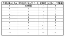
この差分値D1、D2、D3を9通り(−4から4まで)に量子化してそれぞれの差分の量子化値Q1、Q2、Q3を求める。図2に差分値の範囲とその量子化値の対応を示す。T1、T2、T3はあらかじめ定められた非負の整数値である。 The difference values D1, D2, and D3 are quantized in nine ways (from -4 to 4) to obtain quantized values Q1, Q2, and Q3 of the respective differences. FIG. 2 shows the correspondence between the range of the difference value and its quantized value. T1, T2, T3 are predetermined non-negative integer values.
例えば、0〜255の値を取る8ビットの画像に対しては、T1=3、T2=7、T3=21といった値が設定される。このようにして得られたQ1、Q2、Q3の組み合わせ(Q1,Q2,Q3)は、Q1、Q2、Q3がそれぞれ−4から4までの9通りの値を持ち得るので、9×9×9=729通りである。 For example, values of T1 = 3, T2 = 7, T3 = 21 are set for an 8-bit image that takes a value of 0 to 255. The combinations (Q1, Q2, Q3) of Q1, Q2, and Q3 obtained in this way can have nine values from -4 to 4, respectively, so that 9 × 9 × 9 = 729.
ここで状態(Q1,Q2,Q3)で予測誤差eが発生する確率と、状態(−Q1,−Q2,−Q3)で予測誤差−eが発生する確率は同じとして考える。従って、これら2つの状態を統合して365通りに縮退する。この組み合わせを示す情報が上記のコンテキストである。365通りの状態のいずれであるかを表す識別子をSとし、以降、この識別子Sを状態番号と呼ぶ。 Here, the probability that the prediction error e occurs in the states (Q1, Q2, Q3) and the probability that the prediction error -e occurs in the states (-Q1, -Q2, -Q3) are considered to be the same. Therefore, these two states are integrated and degenerated into 365 ways. Information indicating this combination is the above-described context. An identifier indicating which of the 365 states is S, and this identifier S is hereinafter referred to as a state number.
一方、周囲画素a,b,cを用いて着目画素値xに対する予測値pを以下の式により求める。
p=min(a,b) (max(a,b)≦c の場合) or
p=max(a,b) (min(a,b)≧c の場合) or
p=a+b−c (上記以外)
ここで、min(x,y)はx、yの小さい方を返す関数、max(x,y)は大きい方の値を返す関数である。
On the other hand, the predicted value p for the target pixel value x is obtained by the following equation using the surrounding pixels a, b, and c.
p = min (a, b) (when max (a, b) ≦ c) or
p = max (a, b) (when min (a, b) ≧ c) or
p = a + b-c (other than above)
Here, min (x, y) is a function that returns the smaller of x and y, and max (x, y) is a function that returns the larger value.
予測値pの値の取り方は、周囲画素a,b,cの値の大小関係によって切り替わるが、a,b,cが符号化済みの画素であるため、切り替わりに関する付加情報を伝送することなく、符号化側と復号側で同じ予測値pを取ることができることに注意されたい。JPEG−LSでは予測の精度を向上するために、これまでに状態Sで符号化された画素で発生した予測誤差の平均値を参照して予測値pを修正するという技術が用いられているが、ここでは説明を省略する。 The value of the predicted value p is switched according to the magnitude relationship between the values of the surrounding pixels a, b, and c. However, since a, b, and c are already encoded pixels, additional information regarding the switching is not transmitted. Note that the same prediction value p can be taken on the encoding side and the decoding side. In JPEG-LS, in order to improve the accuracy of prediction, a technique is used in which the predicted value p is corrected with reference to the average value of prediction errors that have occurred in the pixels encoded in the state S so far. The description is omitted here.
この予測値pと着目画素xとの差分eを求め、これを非負の整数値に変換してGolomb符号化する。このとき、着目画素のコンテキストに応じて符号化のパラメータkを決定する。 A difference e between the predicted value p and the target pixel x is obtained, converted to a non-negative integer value, and Golomb encoded. At this time, the encoding parameter k is determined according to the context of the pixel of interest.
JPEG−LSではそれぞれの状態Sごとに生起回数N[S]と、その状態で符号化した予測誤差の絶対値和A[S]とを保持する。Golomb符号化のパラメータkは、これら2つの値を用いた以下の条件を満たすものである。なお、「x^y」はxのy乗を示す。
2^(k−1)< A[S]/N[S] ≦ 2^k
In JPEG-LS, the number N [S] of occurrences for each state S and the absolute value sum A [S] of prediction errors encoded in that state are held. The Golomb encoding parameter k satisfies the following conditions using these two values. “X ^ y” indicates x to the power of y.
2 ^ (k−1) <A [S] / N [S] ≦ 2 ^ k
実際には、A[S]/N[S]の除算を行う必要はない。N[S]×2^k≧A[S]となる最小のkを求めれば良い。これにより予測誤差の絶対値平均が大きい状態ではkパラメータとして大きな値が選択され、反対に絶対値平均が小さい状態では小さなkパラメータが選択される。 Actually, it is not necessary to perform the division of A [S] / N [S]. What is necessary is just to obtain the minimum k that satisfies N [S] × 2 ^ k ≧ A [S]. Thus, a large value is selected as the k parameter in a state where the absolute value average of the prediction error is large, and a small k parameter is selected in a state where the absolute value average is small.
符号化の開始時点ではA[S]、N[S]に初期値を設定しておき、符号化処理の過程で随時値を更新していくことにより、動的に各状態の確率分布に追従する。
上述のJPEG−LSによる画像処理装置では、各予測誤差の符号化の都度、kパラメータ決定のための処理を実行する。 In the above-described image processing apparatus based on JPEG-LS, a process for determining the k parameter is executed every time each prediction error is encoded.
除算を行わないようにするなど、処理負荷を軽減する工夫がされているが、不定回数の判定を伴う処理を毎回行うことは処理負荷の観点から効率的とは言えない。 Although some efforts have been made to reduce the processing load such as not performing division, it is not efficient from the viewpoint of processing load to perform the processing with the indefinite number of times of determination every time.
また、予測誤差の絶対値和を保持するには多くの桁数(ビット数)が必要であり、場合によってはA[S]のメモリ容量が問題となることがある。 Also, a large number of digits (number of bits) is required to hold the sum of absolute values of prediction errors, and in some cases, the memory capacity of A [S] may be a problem.
また、予測誤差の絶対値平均に基づいて符号化パラメータkを決定している。このため、例えば状態分離が不十分で統計的性質の変化が大きい情報源を符号化する場合において、大きな予測誤差が発生した際には、それ以降に符号化される多数の予測誤差についてkパラメータが大きくなるなどの影響が及ぶという問題が残る。 Also, the encoding parameter k is determined based on the absolute value average of prediction errors. For this reason, for example, in the case of encoding an information source with insufficient state separation and a large change in statistical properties, when a large prediction error occurs, the k parameter is set for a number of prediction errors encoded thereafter. The problem remains that it will be affected.
本願発明は、上述の問題点に鑑みてなされたものである。そして、本発明の実施態様によれば、動的な確率分布モデルを用いる画像の符号化において、簡易に符号化パラメータを決定し、かつ、良好な符号化性能を実現する技術を提供する。 The present invention has been made in view of the above-mentioned problems. According to the embodiment of the present invention, there is provided a technique for easily determining an encoding parameter and realizing good encoding performance in encoding an image using a dynamic probability distribution model.
かかる課題を解決するため、例えば本発明の画像符号化装置は以下の構成を備える。すなわち、
動的確率分布モデルに基づいて画像データを符号化する画像符号化装置であって、
画像データを画素単位に入力する入力手段と、
該入力手段で入力された着目画素データからGolomb符号化の対象となるシンボルを生成するシンボル生成手段と、
前記シンボル生成手段で生成された着目シンボルを、直前のシンボルを符号化する際に決定された符号化パラメータに従ってGolomb符号化し、符号化データを生成する符号化手段と、
該符号化手段の符号化対象となったシンボルを符号化する際に使用した符号化パラメータが、前記符号化対象のシンボルの符号語を目標符号長とするための符号化パラメータの取り得る範囲内にあるか、当該範囲の上限を超えるか、或いは、当該範囲の下限を下回るかを判断する判断手段と、
前記着目シンボルに後続するシンボルの符号化のため、前記判断手段の判断結果に基づき、前記符号化パラメータを更新する更新手段とを備える。
In order to solve this problem, for example, an image encoding device of the present invention has the following configuration. That is,
An image encoding device that encodes image data based on a dynamic probability distribution model,
Input means for inputting image data in units of pixels;
Symbol generation means for generating a symbol to be subjected to Golomb encoding from pixel-of-interest data input by the input means;
Encoding means for generating the encoded data by performing Golomb encoding on the target symbol generated by the symbol generating means according to the encoding parameter determined when encoding the immediately preceding symbol ;
The encoding parameter used when encoding the symbol to be encoded by the encoding means is within a range that can be taken by the encoding parameter for setting the codeword of the symbol to be encoded as a target code length. Determining means for determining whether the value is above the upper limit of the range or below the lower limit of the range;
Updating means for updating the coding parameter based on a determination result of the determination means for encoding a symbol subsequent to the symbol of interest ;
本発明によれば、処理負荷およびメモリコストの少ない簡易な方法で符号化パラメータを決定することができ、かつ、画像データを良好な圧縮性能で符号化可能とする。 According to the present invention, it is possible to determine an encoding parameter by a simple method with low processing load and memory cost, and to enable encoding of image data with good compression performance.
以下添付図面を参照して、本発明を好適な実施形態に従って詳細に説明する。 Hereinafter, the present invention will be described in detail according to preferred embodiments with reference to the accompanying drawings.
<第1の実施形態>
図1は本実施形態に係る画像処理装置の機能構成を示すブロック構成図である。
<First Embodiment>
FIG. 1 is a block diagram illustrating a functional configuration of the image processing apparatus according to the present embodiment.
図1に示すように、本実施形態に係る画像処理装置は、画像入力部101、ラインバッファ102、予測器103、予測誤差生成部104、予測順位変換部105、Golomb符号化部106、kパラメータ更新部107、符号列形成部108とを備える。同図において109は信号線を示す。
As shown in FIG. 1, the image processing apparatus according to the present embodiment includes an
以下、図1を参照して、本実施形態に係る画像処理装置が行う画像符号化処理について説明する。ここでは、符号化対象画像は、各画素が8ビット(0〜255の範囲)の輝度値または濃度値を表現した画素データにより構成される、モノクロ画像データであるものとする。しかしながら、本方式はRGBやCMYKなど、1画素が複数のコンポーネント(色)で表現されるカラー画像や、各コンポーネントが8ビット以上のビット精度で表現される画像データに対しても同様に適用可能である。例えば、カラー画像に適用する場合には、コンポーネント毎に分離して、それぞれをモノクロ画像と同様に符号化すれば良い。なお、符号化対象画像は水平方向W画素、垂直方向G画素により構成されるものとする。
Hereinafter, with reference to FIG. 1, an image encoding process performed by the image processing apparatus according to the present embodiment will be described. Here, it is assumed that the image to be encoded is monochrome image data in which each pixel is composed of pixel data expressing a luminance value or density value of 8 bits (
次に、本実施形態の画像処理装置での各部の動作について説明する。 Next, the operation of each unit in the image processing apparatus of this embodiment will be described.
画像入力部101は、符号化対象画像データの画素データxを入力する。この入力はラスタースキャン順とする。入力源は、イメージスキャナとするが、画像データファイルを記憶している記憶媒体でもあっても良く、その入力源の種類は問わない。
The
ラインバッファ102は画像データを2ライン分格納する記憶容量を持ち、画像入力部101から入力される画像データを順次格納していく。つまり、ラインバッファ102に必要とされる容量は2×Wバイトである。ラインバッファ102に保持する2ライン分の画素データは符号化開始時点で所定の値で初期化される。画素の初期値としては符号化装置と復号装置で共通に設定可能な値であれば良い。ここでは説明の簡略化のため、符号化処理を開始する際に、ラインバッファ102を「0」で初期化するものとする。
The
予測器103は画像入力部101から入力される画素(以降、着目画素と呼ぶ)について、符号化済みの周囲画素a,b,cを参照して予測値pを生成する。着目画素xと周囲画素a,b,cの位置関係は図3に示す通りである。符号化済みの周囲画素a,b,cはラインバッファ102から供給される。なお、着目画素xがラインの先頭である場合やラインの最後の画素である場合、周囲画素a、b、cのいずれかが符号化対象画像の範囲外となることがある。このような場合には、符号化装置と復号装置で共通の値を用いるが、ここでは画像の範囲外の値は0とする。本実施形態では予測値pを以下の式により求める。
p=min(a,b) (max(a,b)≦c の場合) or
p=max(a,b) (min(a,b)≧c の場合) or
p=a+b−c (上記以外)
The
p = min (a, b) (when max (a, b) ≦ c) or
p = max (a, b) (when min (a, b) ≧ c) or
p = a + b-c (other than above)
なお、予測値生成には上記方法以外にも様々な方法を用いることが可能である。例えば、JPEG標準方式のロスレス符号化で使用可能な7つの予測式のように、別の予測式を用いても良い。また、JPEG−LS標準方式のように、符号化済みの画素で平均的に発生した予測誤差値を用いて上記予測値pを補正することで予測の精度を高めるといった方法を用いることもできる。 It should be noted that various methods other than the above method can be used to generate the predicted value. For example, another prediction formula may be used, such as seven prediction formulas that can be used in the lossless encoding of the JPEG standard method. Further, as in the JPEG-LS standard method, it is possible to use a method in which the prediction accuracy is improved by correcting the prediction value p using the prediction error value generated on average in the encoded pixels.
予測誤差生成部104は予測器103により生成された予測値pと画像入力部101から入力される着目画素値xとの差分「x−p」を演算し、その結果を予測誤差eとして出力する。
The prediction
予測順位変換部105は予測誤差生成部104で求めた予測誤差eを以下の式により非負の整数値M(e)にマップする。以降、M(e)を予測順位と呼ぶ。
M(e)= 2×e (e≧0の場合)
M(e)= −2×e−1 (e<0の場合)
上記の結果、M(e)は非負の整数となり、それが偶数か奇数かでもって予測誤差eの正負の符号が識別できる。
The prediction
M (e) = 2 × e (when e ≧ 0)
M (e) = − 2 × e−1 (when e <0)
As a result, M (e) is a non-negative integer, and the sign of the prediction error e can be identified based on whether it is even or odd.
Golomb符号化部106はkパラメータ更新部107の内部に保持するkパラメータを用いて、予測順位変換部105から出力される予測順位M(e)をGolomb符号化し、2値シンボル列を出力する。
The
Golomb符号は非負の整数値を符号化対象とし、パラメータ変数mによって異なる複数の確率モデルによる符号化が可能であるという特徴を持つ。また、符号化対象シンボルとパラメータ変数mから符号語を導出することができるため、符号表が不要という利点もある。以下の説明ではパラメータ変数mが2^kとなるGolomb符号の特殊形に限定し、kをパラメータ変数として説明する。このようなGolomb符号の一形態がISOとITU-Tから国際標準勧告されるJPEG-LS(ISO/IEC 14495−1|ITU-T Recommendation T.87)において予測誤差の符号化方式として採用されている。 The Golomb code has a feature that a non-negative integer value can be encoded, and encoding can be performed using a plurality of probability models that differ depending on the parameter variable m. Further, since the code word can be derived from the encoding target symbol and the parameter variable m, there is also an advantage that a code table is unnecessary. In the following description, the parameter variable m is limited to a special form of Golomb code where 2 ^ k, and k is described as a parameter variable. One form of such Golomb code is adopted as a prediction error encoding method in JPEG-LS (ISO / IEC 14495-1 | ITU-T Recommendation T.87) recommended by ISO and ITU-T as an international standard. Yes.
符号化対象の非負の整数値nを符号化パラメータkでGolomb符号化する手順は次の通りである。まず、nをkビット右シフトして整数値uを求める。平たく言えば、整数値uは、nを2^kで除算した商を意味する。 The procedure for Golomb encoding the non-negative integer value n to be encoded with the encoding parameter k is as follows. First, n is shifted right by k bits to obtain an integer value u. Put simply, the integer value u means the quotient obtained by dividing n by 2 ^ k.
シンボルnに対する符号は、u個の「0」に続く「1」(可変長部)と、nの下位kビット(固定長部)の組み合わせにて構成する。図16にk=0,1,2におけるGolomb符号の例を示しておく。 The code for the symbol n is composed of a combination of “1” (variable length portion) following u “0” and lower k bits (fixed length portion) of n. FIG. 16 shows an example of the Golomb code at k = 0, 1, 2.
例えば、k=2(従ってm=4)で、シンボルn=5の場合、u=floor(5/4)=1となるので、可変長部は2進“01”となる。また、シンボルnの下位2ビットは“01”となるので、k=2の場合のシンボル「5」のGolomb符号語は“0101”となり、符号長は4ビットとなる。 For example, if k = 2 (thus m = 4) and the symbol n = 5, u = floor (5/4) = 1, so the variable length portion is binary “01”. Further, since the lower 2 bits of the symbol n are “01”, the Golomb codeword of the symbol “5” when k = 2 is “0101”, and the code length is 4 bits.
なお、ここに述べた符号の構成方法は一例であり、固定長部と可変長部の順序を逆にしても一意復号可能な符号を構成することができる。また、0と1を反対にして符号を構成しても良い。 The code configuration method described here is merely an example, and a uniquely decodable code can be configured even if the order of the fixed-length part and the variable-length part is reversed. Also, the code may be configured with 0 and 1 reversed.
kパラメータ更新部107は、Golomb符号化部106により予測順位変換部105から出力される予測順位M(e)の符号化後が行われた後に、内部に保持するkパラメータの更新処理を行う。更新処理は、符号化した予測順位M(e)の値と現在保持するkパラメータで最小符号長が得られる範囲(以降、最適シンボル範囲と呼ぶ)とを比較し、必要に応じてkの値を+1、あるいは−1することにより行われる。
The k
図5AはGolomb符号の、各シンボルの値(縦軸)と、kパラメータ(横軸)と2次元空間における符号長を示すテーブルである。図示では、0〜28までの符号化対象シンボル(予測順位M(e)に対応する)を、k=0〜5のそれぞれ符号化パラメータで符号化した場合に発生する符号長(ビット数)を表している。 FIG. 5A is a table showing values of each symbol (vertical axis), k parameter (horizontal axis), and code length in a two-dimensional space of the Golomb code. In the figure, the code length (number of bits) generated when encoding target symbols from 0 to 28 (corresponding to the prediction order M (e)) are encoded using the encoding parameters of k = 0 to 5 respectively. Represents.
図示のテーブルでは、3つの領域に分けて示している。1つ目の領域は、個々のシンボルに着目し、その符号語の符号長が最小(最短)となる領域50である。残りの2つは、領域50で分断される領域51、52である。領域51は、領域50を規定する符号化パラメータkの値よりも大きな符号化パラメータkと、最小符号長とはならない符号長で定義される領域と言い換えることができる。また、領域52は、領域50を規定する符号化パラメータkの値よりも小さな符号化パラメータkと、最小符号長とはならない符号長で定義される領域と言い換えることができる。
The illustrated table is divided into three areas. The first area is an
例えば、符号化対象シンボルが「8」であり、符号化パラメータk=2乃至4の範囲では最小符号長「5」となる。従って、シンボル「8」においては、符号化パラメータk=2乃至4の範囲の符号長が「5」となる位置は、領域50内にある。
For example, when the encoding target symbol is “8” and the encoding parameter k = 2 to 4, the minimum code length is “5”. Therefore, in the symbol “8”, the position where the code length in the range of the encoding parameter k = 2 to 4 is “5” is in the
また、符号化対象シンボルが「8」であり、符号化パラメータk=5では、符号長が「6」となり、最小符号長「5」とはならない。それ故、シンボル「8」においては、符号化パラメータk=5の符号長が「6」となる位置は、領域51内にある。
In addition, when the encoding target symbol is “8” and the encoding parameter k = 5, the code length is “6”, and the minimum code length is not “5”. Therefore, in the symbol “8”, the position where the code length of the encoding parameter k = 5 is “6” is in the
同様に、符号化対象シンボルが「8」であり、符号化パラメータk=0、1では、符号長が「9」or「6」となり、やはり最小符号長「5」とはならない。それ故、シンボル「8」においては、符号化パラメータk=0、1の符号長が「9」or「6」となる位置は、領域52内にある。
Similarly, when the encoding target symbol is “8” and the encoding parameters k = 0 and 1, the code length is “9” or “6”, and the minimum code length is not “5”. Therefore, in the symbol “8”, the position where the code length of the encoding parameter k = 0, 1 is “9” or “6” is in the
本実施形態におけるkパラメータ更新部107は、符号化対象の予測順位M(e)が領域51内にあった場合、次画素の符号化時には、より小さいkパラメータが適切と判断し、kの値をより小さな値に補正する。具体的には、次画素の符号化に備えて、パラメータkから1を減じる。
In the present embodiment, the k
また、符号化した予測順位M(e)が領域52内にあった場合、より大きなkパラメータが適切と判断し、kの値をより大きな値に補正する。具体的には、kに1を加えて更新する。
If the encoded prediction order M (e) is within the
そして、符号化した予測順位M(e)が領域50内にあった場合、現状のkパラメータが適切と判断し、kの値は補正せず、維持する。
If the encoded prediction order M (e) is within the
なお、図示の領域51、52の境界はパラメータkから導出することができる。符号化対象シンボルの値をnで表すとき、領域51は、「n<2^(k−1)」の関係を満たす範囲であり、領域52は3×2^k≦nの範囲である。換言すれば、図5Aのテーブルを全て記憶する必要はなく、領域50を定義する情報のみ記憶すればよい。領域50は、各シンボルの値と、それぞれのシンボル毎に、それを符号化した際の最小符号長となるパラメータkの下限値と上限値を記憶すればよい。
Note that the boundaries between the
また、この判定処理を不要とするため、図5Bに示すような、テーブルを予めパラメータ更新部107が記憶保持しても構わない。図5Bのテーブルは、図5Aのテーブルに、次回の符号化に備えた補正値(−1、0、+1)の項目を追加したものである。領域50内での補正値は“0”、領域51内での補正値は“−1”、そして、領域52内での補正値は“+1”である。従って、補正値H(=−1,0、+1)はH(n,k)と表現できるので、この値H(n,k)を現在のkパラメータに足し込むことで、kパラメータを更新すればよい。
Further, in order to eliminate this determination process, the
符号列形成部108はGolomb符号化部106から出力される符号列(2値シンボル列)を結合させ、必要な付加情報を加えて本画像処理装置の出力となる符号化データを形成して信号線109より出力する。出力先が記憶装置であれば、ファイルとして格納する。
The code
図9は本画像処理装置の出力符号列の構成を示す図である。出力符号列の先頭には、画像を復号するために必要となる情報、例えば、画像の水平方向画素数、垂直方向画素数、色空間を表す属性情報、コンポーネント数、各コンポーネントのビット数などの付加情報がヘッダとして付けられる。 FIG. 9 is a diagram showing a configuration of an output code string of the image processing apparatus. At the beginning of the output code string, information necessary for decoding the image, such as the number of pixels in the horizontal direction, the number of pixels in the vertical direction, attribute information indicating the color space, the number of components, the number of bits of each component, etc. Additional information is attached as a header.
図4は本実施形態に係る画像処理装置による符号化対象画像データの符号化処理の流れを示すフローチャートである。以下、図4に示したフローチャートを参照して、本実施形態に係る画像処理装置が行う画像符号化処理の全体的な流れについて説明する。 FIG. 4 is a flowchart showing a flow of encoding processing of encoding target image data by the image processing apparatus according to the present embodiment. The overall flow of the image encoding process performed by the image processing apparatus according to this embodiment will be described below with reference to the flowchart shown in FIG.
まず、符号化処理に先立ち、ラインバッファ102に格納される画素データ、およびkパラメータ更新部107に保持される符号化パラメータkの初期化が行われる。本実施形態ではラインバッファ102の画素データを全て0に初期化し、kパラメータ更新部107が保持するkパラメータを「2」に設定する(ステップS400)。続いて、画像入力部101はラスタースキャン順に画像データの入力を開始し、入力した画像データの各画素データをラインバッファ102に格納すると共に、予測誤差生成部104に供給する(ステップS401)。
First, prior to the encoding process, the pixel data stored in the
次に、ラインバッファ102から着目画素の周囲画素a,b,cを読み出し、予測器103にて予測値pを生成する(ステップS402)。予測誤差生成部104は、着目画素xと予測器103の生成した予測値pとの差分を求め、予測誤差eとして出力する(ステップS403)。予測順位変換部105は、この予測誤差eを予測順位M(e)に変換する(ステップS404)。Golomb符号化部106は、kパラメータ更新部107の内部に保持するkパラメータを用いて、予測順位M(e)をGolomb符号化する(ステップ405)。
Next, the surrounding pixels a, b, and c of the pixel of interest are read from the
続いてkパラメータ更新部107にて、符号化した予測順位M(e)と更新前のkパラメータにおける最適範囲との比較が行われ、自身が保持するkパラメータを必要に応じて更新する(ステップS406)。つまり、予測順位M(e)と、Golomb符号化部106で使用したkパラメータで示される位置が、図5A又は図5Bの領域50乃至52のどの領域内にあるかを判断し、いずれの領域にあるかに基づき次の画素の符号化する際に利用することになるkパラメータを更新(補正)する。
Subsequently, the k
次いで、符号化した画素が画像の最後の画素かどうかを判定し(ステップS407)、最後の画素である場合には符号化処理を終了し、そうでない場合にはステップ401へと処理を移し、次の画素の符号化処理を行う。 Next, it is determined whether or not the encoded pixel is the last pixel of the image (step S407). If the encoded pixel is the last pixel, the encoding process is terminated; otherwise, the process proceeds to step 401. The next pixel is encoded.
以上の処理により、画像全体の符号化が行われる。なお、符号化処理は必ずしもこの順序で行わなければならないという訳ではない。例えば、ここでは画素データの読み込み(ステップS401)、予測値の生成(ステップS402)という順番で説明したが、順序を逆にしても良い。また、更新前のkパラメータを正しく受け渡しできるならば、Golomb符号化(ステップS405)とkパラメータの更新(ステップS406)の順序を変える、あるいは並列に行うといった変更を行っても良い。 With the above processing, the entire image is encoded. Note that the encoding process does not necessarily have to be performed in this order. For example, here, the pixel data is read (step S401) and the predicted value is generated (step S402). However, the order may be reversed. If the k parameter before update can be correctly transferred, the order of Golomb encoding (step S405) and k parameter update (step S406) may be changed or may be changed in parallel.
ここで、予測順位変換部105から順に出力される予測順位の列“0,0,2,0,0,1,0,3,0…”を符号化する場合を例にとり、符号化に使用するkパラメータの値と更新処理の内容、および更新処理後のk値の推移を図6に示す。
Here, a case where the prediction order sequence “0, 0, 2, 0, 0, 1, 0, 3, 0...” Output in order from the prediction
以下、kパラメータの変化を順に説明する。符号化の開始時にkパラメータの初期値を“2”に設定し、最初のシンボル“0”はこのk=2を用いてGolomb符号化する。k=2に対してシンボル“0”は、図5Aの領域51に該当する。従って、kから1を減じて、k=1と更新する。
Hereinafter, changes in the k parameter will be described in order. The initial value of the k parameter is set to “2” at the start of encoding, and the first symbol “0” is Golomb encoded using this k = 2. For k = 2, the symbol “0” corresponds to the
2番目のシンボル“0”を更新後のk(この場合k=1)で符号化する。この場合、シンボル“0”は、同じく図5Aの領域51に該当するため、kから1を減じてk=0と更新する。
The second symbol “0” is encoded with the updated k (in this case, k = 1). In this case, since the symbol “0” similarly corresponds to the
次に、シンボル“2”をk=0で符号化する。シンボル“2”はk=0の最適シンボル範囲にあるため、kの値は変化させない。以降、同様にシンボル列“0,0,1,0”を符号化するが、同じ理由からkの値に変化は起こらない。 Next, the symbol “2” is encoded with k = 0. Since the symbol “2” is in the optimum symbol range of k = 0, the value of k is not changed. Thereafter, the symbol string “0, 0, 1, 0” is similarly encoded, but the value of k does not change for the same reason.
続いて、シンボル“3”をk=0で符号化し、シンボルが領域52に該当するため1を加えて、k=1と更新する。次のシンボル“0”をk=1で符号化し、領域51に該当するため1を減じて、k=0と更新する。このようにして、符号化とパラメータkの更新処理が行われる。この例からも、符号化対象シンボルの局所的な性質に合わせてkパラメータが変更されていく様子が分かる。
Subsequently, the symbol “3” is encoded with k = 0, and since the symbol corresponds to the
本実施形態の画像処理装置で生成した符号化データを復号するにはヘッダに示される付加情報を参照して、符号化処理の逆の手順でそれぞれの画素を復号していくようにすれば良い。このとき、各シンボルの復号においてGolomb符号化のkパラメータは符号化側と復号側で同じ値を用いる。即ち、復号側でも符号化側と同じ初期値を与えて復号を開始し、復号したシンボルが現在のkパラメータに対して最適シンボル範囲にあるか否かを判定し、符号化時と同じアルゴリズムで必要に応じて更新していく。 In order to decode the encoded data generated by the image processing apparatus of the present embodiment, each pixel may be decoded in the reverse procedure of the encoding process with reference to the additional information indicated in the header. . At this time, in decoding each symbol, the same value is used for the k parameter of Golomb encoding on the encoding side and the decoding side. That is, on the decoding side, the same initial value as that on the encoding side is given to start decoding, and it is determined whether or not the decoded symbol is in the optimum symbol range with respect to the current k parameter. Update as needed.
図15は復号側の画像処理装置の機能構成を示すブロック図である。先に説明した図1と共通のブロックについては同じ番号を付し、説明を省略する。図に示すように復号側の画像処理装置は、符号化データ入力部1501、Golomb符号復号部1502、予測順位逆変換部1503、画素値復元部1504、ヘッダ解析部1505、ラインバッファ102、予測器103、kパラメータ更新部107とを備える。
FIG. 15 is a block diagram showing a functional configuration of the image processing apparatus on the decoding side. Blocks that are the same as those in FIG. 1 described above are given the same numbers, and descriptions thereof are omitted. As shown in the figure, an image processing apparatus on the decoding side includes an encoded
以下、復号処理を行う画像処理装置の各処理部の動作について説明する。 The operation of each processing unit of the image processing apparatus that performs the decoding process will be described below.
符号化データ入力部1501は復号対象となる符号化データを入力する。このとき、符号化データ入力部1501は、符号化データの構造解析を行い、ヘッダ部はヘッダ解析部1505へ、画素符号化データはGolomb符号復号部1502へと渡す。
The encoded
ヘッダ解析部1505は符号化データ入力部から送られるヘッダを解析し、符号化された画像データの水平、垂直方向画素数など、復号処理に必要な情報を取り出し、画像処理装置の制御に反映させる。
The
Golomb符号復号部1502はkパラメータ更新部107に保持するkパラメータを取得し、これを用いて予測順位M(e)にまで復元する。
The Golomb
kパラメータ更新部107は先に述べた符号化の際の更新処理と同じ方法により、復号された予測順位M(e)に基づいて必要に応じてkパラメータの更新を行う。
The k
予測順位逆変換部1503はGolomb符号復号部1502で復号された予測順位M(e)から以下の式により予測誤差eを復元する。
e= M(e)/2 (M(e)が偶数の場合 )
e=−(M(e)+1)/2 (M(e)が奇数の場合 )
The prediction order
e = M (e) / 2 (when M (e) is an even number)
e =-(M (e) +1) / 2 (when M (e) is an odd number)
画素値復元部1504は予測順位逆変換部1503で復元される予測誤差eと予測器103にて生成される予測値pから、e+pにより着目画素値xを復号して出力する。復号した画素値xはラインバッファ102に格納され、以降の画素の予測値を生成する際に利用される。
The pixel
画像を構成する全ての画素が復号されるまで、Golomb符号復号部1502から画素値復元部1504の処理を繰り返し行うことにより、符号化データから画像データの復号を行う。
The image data is decoded from the encoded data by repeatedly performing the processes of the Golomb
以上の説明のように、本実施形態に係る画像処理装置では、符号化したシンボル、または復号したシンボルが現在のkパラメータにおける最適シンボル範囲にあるか否かを判定して、最適シンボル範囲にない場合に+1または−1して更新し、適切なkパラメータとなるよう制御している。これにより局所的に統計的性質の異なる画像データであっても性質の変化に追従した効率の良い符号化ができる。 As described above, in the image processing apparatus according to the present embodiment, it is determined whether the encoded symbol or the decoded symbol is in the optimum symbol range in the current k parameter, and is not in the optimum symbol range. In this case, it is updated to +1 or -1, and is controlled so as to be an appropriate k parameter. As a result, even image data having locally different statistical properties can be efficiently encoded following changes in properties.
<第1の実施形態の変形例>
上記の実施形態を、パーソナルコンピュータ等の汎用情報処理装置と、それ上で実行されるコンピュータプログラムで実現しても構わない。
<Modification of First Embodiment>
The above embodiment may be realized by a general-purpose information processing apparatus such as a personal computer and a computer program executed thereon.
図14は本変形例に係る情報処理装置の基本構成を示す図である。図中、1401はCPUで、RAM1402やROM1403に記憶されているプログラムやデータを用いて本装置全体の制御を行うと共に、後述する画像符号化処理を実行する。
FIG. 14 is a diagram showing a basic configuration of an information processing apparatus according to this modification. In the figure,
1402はRAMで、外部記憶装置1407や記憶媒体ドライブ1408、若しくはI/F1409を介して外部装置からダウンロードされたプログラムやデータを記憶する為のエリアを備えると共に、CPU1401が各種の処理を実行する際に使用するワークエリアも備える。
A
1403はROMで、ブートプログラムや本装置の設定プログラムやデータを格納する。
1404、1405は夫々キーボード、マウス等のポインティングデバイスで、CPU1401に対して各種の指示を入力することができる。
1406は表示装置で、CRTや液晶画面などにより構成されており、画像や文字などの情報を表示することができる。 A display device 1406 includes a CRT, a liquid crystal screen, and the like, and can display information such as images and characters.
1407は外部記憶装置で、ハードディスクドライブ装置等の大容量情報記憶装置であって、ここにOSや後述する画像符号化、復号化処理の為のアプリケーションプログラム、符号化対象の画像データなどが保存されている。OSやアプリケーションは、CPU1401による制御によって、RAM1402上の所定のエリアにロードすることで、実行されることになる。
Reference numeral 1407 denotes an external storage device, which is a large-capacity information storage device such as a hard disk drive device, in which an OS, an application program for image encoding and decoding processing described later, image data to be encoded, and the like are stored. ing. The OS and application are executed by being loaded into a predetermined area on the
1408は記憶媒体ドライブで、CD−ROMやDVD−ROMなどの記憶媒体に記録されたプログラムやデータを読み出してRAM1402や外部記憶装置1407に出力するものである。なお、この記憶媒体に後述する画像符号化処理の為のプログラム、符号化対象画像を記録しておいても良く、その場合、記憶媒体ドライブ1408は、CPU1401による制御によって、これらのプログラムやデータをRAM1402上の所定のエリアにロードする。
A storage medium drive 1408 reads programs and data recorded on a storage medium such as a CD-ROM or DVD-ROM and outputs them to the
1409はI/Fで、このI/F1409によって外部装置を本装置に接続し、本装置と外部装置との間でデータ通信を可能にするものである。例えはI/F1409を介して符号化対象となる画像データを本装置の本装置のRAM1402や外部記憶装置1407に入力することや、逆に、本装置のRAM1402や外部記憶装置1407から生成した画像符号化データを装置外部に出力することができる。1410は上述の各部を繋ぐバスである。
画像符号化処理を行なう場合、外部記憶装置1407から対応するプログラムをRAM1402にロードし、CPU1401がその処理を実行する。この符号化処理のプログラムは、基本的に図4のフローチャートに従って処理を行なえば良い。また、そのプログラムは、図1に示すような各構成に相当するモジュール(関数、サブルーチンと言っても良い)で構成すれば良いであろう。ただし、ラインバッファ108は、RAM1402にその容量分のデータ領域を確保することになる。
When the image encoding process is performed, a corresponding program is loaded from the external storage device 1407 into the
また、復号処理に係るプログラムも、図15に示すモジュールで構成すれば良いのは明らかであろう。 It will be apparent that the program relating to the decoding process may be configured by the modules shown in FIG.
<第2の実施形態>
次に、第2の実施形態を以下に説明する。第1の実施形態の画像処理装置では符号化対象のシンボルが最適シンボル範囲外となる度に符号化パラメータkを増減して、補正させた。この場合、情報源の統計的性質の変化にすばやく対応できる利点がある反面、性質の変化の少ない情報源においては安定性が問題となる。
<Second Embodiment>
Next, a second embodiment will be described below. In the image processing apparatus according to the first embodiment, the encoding parameter k is increased or decreased every time the encoding target symbol is outside the optimum symbol range. In this case, there is an advantage that a change in the statistical property of the information source can be quickly dealt with, but stability is a problem in an information source with a small change in property.
例えば、それぞれのkパラメータで符号化効率が最大となる確率分布f(n、k)=(1/2)^L(n,k)について考える。L(n,k)は符号化対象シンボルnを符号化パラメータkでGlomb符号化した場合の符号長であり、L(n,k)=k+1+floor(n/(2^k)}で与えられる。なお、x^yはxのy乗、floor(x)はxを超えない最大整数を返す関数を表わす。 For example, consider a probability distribution f (n, k) = (1/2) ^ L (n, k) that maximizes the coding efficiency for each k parameter. L (n, k) is the code length when the encoding target symbol n is Glomb-encoded with the encoding parameter k, and is given by L (n, k) = k + 1 + floor (n / (2 ^ k)}. X ^ y represents a function that returns x to the power of y, and floor (x) returns a maximum integer not exceeding x.
図7にk=1の場合の確率分布f(n、1)を図示する。 FIG. 7 illustrates a probability distribution f (n, 1) when k = 1.
確率分布f(n、k)について図5Aに示した領域52に属する何れかのシンボルが出現する確率、即ち、或るkにおいて領域52に属するシンボルの出現確率の和を調べると、どのkパラメータにおいても12.5%であることが分かる。
When the probability that any symbol belonging to the
同様に領域51について見ると、k=0の場合を除いて、領域51のシンボルの出現確率は25%となっている。即ち、あるkパラメータ(k≠0)で、その理想的な確率分布の情報源f(n、k)を符号化している場合であっても、37.5%(=12.5%+25%)の確率でkパラメータが変化することを意味する。
Similarly, regarding the
図8(a)はk=0である場合、同図(b)はk>0である場合に、それぞれf(n、k)の確率分布を持つ情報源のシンボルを符号化して起こるkパラメータの遷移を示している。 FIG. 8A shows the k parameter generated by encoding the symbols of the information source having the probability distribution of f (n, k) when k = 0, and FIG. 8B shows the probability distribution of f (n, k) when k> 0. The transition is shown.
ここでは本発明の第2の実施形態として、kパラメータの変動を抑制し、安定性を向上させる方法について述べる。 Here, as a second embodiment of the present invention, a method for suppressing the fluctuation of the k parameter and improving the stability will be described.
図10は、本第2の実施形態に係る画像処理装置の機能構成を示すブロック図である。第1の実施形態で説明した図1と共通のブロックについては同じ番号を付し、説明を省略する。 FIG. 10 is a block diagram illustrating a functional configuration of the image processing apparatus according to the second embodiment. Blocks that are the same as those in FIG. 1 described in the first embodiment are given the same numbers, and descriptions thereof are omitted.
本第2の実施形態に係る画像処理装置は、画像入力部101、ラインバッファ102、予測器103、予測誤差生成部104、予測順位変換部105、Golomb符号化部106、コンテキスト生成部1001、kパラメータ更新部1002、符号列形成部108を備える。また、同図において109は信号線を示す。
The image processing apparatus according to the second embodiment includes an
なお、本第2の実施形態に係る画像処理装置の基本構成は、それぞれの機能を専用のハードウェアによって構成しても良い。また、先に説明した第1の実施形態の変形例と同様に図14に示す構成とし、図10に示す各部の機能をコンピュータに実現させるプログラムにより実現するものとしても構わない。後者の場合、そのプログラムは上記外部記憶装置1407や記憶媒体ドライブ1408、もしくはI/F1409を介して外部装置からRAM1402にロードされ、CPU1401が実行することになる。
Note that, in the basic configuration of the image processing apparatus according to the second embodiment, each function may be configured by dedicated hardware. Moreover, it is good also as what implement | achieves the structure shown in FIG. 14 similarly to the modification of 1st Embodiment demonstrated previously, and implement | achieved by the program which makes a computer implement | achieve the function of each part shown in FIG. In the latter case, the program is loaded from the external device to the
以下、図10を用いて本第2の実施形態に係る画像処理装置が行う処理について説明する。 Hereinafter, processing performed by the image processing apparatus according to the second embodiment will be described with reference to FIG.
本第2の実施形態に係る画像処理装置の符号化対象とする画像データは、第1の実施形態と同じく、各画素8ビットで0〜255の範囲の輝度値を表現したモノクロ画像データとして説明する。ただし、RGBやCMYKカラー画像など、複数コンポーネント(成分)で構成される画像データにも適用可能である。また、符号化対象の画像データはラスタースキャン順に各画素の値を並べて構成されるものとする。画像は水平方向W画素、垂直方向H画素により構成されるものとする。 The image data to be encoded by the image processing apparatus according to the second embodiment is described as monochrome image data in which luminance values in the range of 0 to 255 are expressed by 8 bits of each pixel, as in the first embodiment. To do. However, the present invention can also be applied to image data composed of a plurality of components (components) such as RGB and CMYK color images. Further, it is assumed that the image data to be encoded is configured by arranging the values of the respective pixels in the raster scan order. The image is assumed to be composed of horizontal W pixels and vertical H pixels.
本第2の実施形態の画像処理装置においても第1の実施形態の画像処理装置と同様に、画像入力部101は符号化対象となる画素データxを入力し、その画素データxをラインバッファ102に格納する。先に説明した予測器103、予測誤差生成部104、予測順位変換部105によって、エントロピ符号化の対象となる非負の整数値M(e)が生成される。
Also in the image processing apparatus according to the second embodiment, as in the image processing apparatus according to the first embodiment, the
一方、コンテキスト生成部1001では、着目画素xの周囲画素a,b,c,dをラインバッファ102から読み出し、着目画素の周囲の状態を表すコンテキストを生成する。本実施形態ではJPEG−LSと類似の手法により、状態番号Sが0〜728である729通りの状態に分離するものとする。
On the other hand, the
従来技術の説明部分で述べた通り、周辺画素a,b,c,dについて、aとb、bとc、cとdの差分をそれぞれ図2のテーブルに従って量子化してQ1、Q2、Q3を得る。この組み合わせを一意に表わす状態番号Sを生成する。本第2の実施の形態では以下の式により状態番号Sを定める。
S=81×Q1+9×Q2+Q3+364
As described in the description section of the prior art, for peripheral pixels a, b, c, and d, the differences between a and b, b and c, and c and d are quantized according to the table of FIG. 2 to obtain Q1, Q2, and Q3, respectively. obtain. A state number S uniquely representing this combination is generated. In the second embodiment, the state number S is determined by the following equation.
S = 81 × Q1 + 9 × Q2 + Q3 + 364
なお、JPEG−LSと同様に状態(Q1,Q2,Q3)と状態(−Q1、−Q2、−Q3)と統合して365状態に縮退したり、a,b,c,d以外の周辺画素を参照してコンテキストを生成しても構わない。 As in JPEG-LS, the state (Q1, Q2, Q3) and the state (-Q1, -Q2, -Q3) are integrated into a 365 state, or peripheral pixels other than a, b, c, d The context may be generated by referring to.
kパラメータ更新部1002の内部には各状態Sに応じたkパラメータを格納する配列K[S]と、後述する更新処理にて参照するフラグ配列F[S]を保持する。符号化の開始時に配列K[S](S=0、1、2、…)は初期値(本実施形態では2とする)に設定され、フラグ配列F[S](S=0、1、2、…)を“0”に初期化する。
The k
図11は、着目画素xの符号化時のkパラメータ更新部1002の処理の流れを示すフローチャートである。同図を用いて各画素で行われるkパラメータ更新部1002の処理の流れを説明する。
FIG. 11 is a flowchart illustrating a process flow of the k
まず、kパラメータ更新部1002は、コンテキスト生成部1001から出力される状態番号Sと予測順位変換部105から出力される予測順位M(e)を取得する(ステップS1101)。次いで、kパラメータ更新部1002は、入力された状態番号Sに対応するkパラメータを配列要素K[S]により取得し、それをGolomb符号化部106へと出力する(ステップS1102)。これにより、Golomb符号化部106は、予測順位M(e)の符号化を行うことになる。
First, the k
次いで、現在のkパラメータの値、即ちK[S]と、シンボルである予測順位M(e)とで示される位置(K[S],M(e))が、領域51内にあるか否かを判断する(ステップS1103)。
Next, whether or not the position (K [S], M (e)) indicated by the current k parameter value, that is, K [S] and the prediction rank M (e), which is a symbol, is in the
これは、現在のkパラメータの値が、予測順位M(e)の最小符号長となるkパラメータの上限値を超えているか否かを判断する、と言い換えることもできる。 In other words, it is determined whether or not the current value of the k parameter exceeds the upper limit value of the k parameter that is the minimum code length of the prediction order M (e).
位置(K[S],M(e))が、領域51内にあると判断した場合には、ステップS1107へ処理を進め、フラグ配列の要素F[S]が“1”であるか否かを判定する。“1”でないと判定した場合には、フラグ配列要素F[S]に“1”を設定する(ステップS1110)。また、ステップS1107にて、フラグ配列の要素F[S]が“1”であると判定した場合には、K[S]から“1”を減じて更新し(ステップS1108)、フラグ配列の要素F[S]に“0”を設定する(ステップS1109)。
If it is determined that the position (K [S], M (e)) is in the
一方、ステップS1103にて、位置(K[S],M(e))が領域51に属さないと判断された場合には、ステップS1104に進んで、位置(K[S],M(e))が領域52内にあるか否かを判定する。
On the other hand, if it is determined in step S1103 that the position (K [S], M (e)) does not belong to the
これは、現在のkパラメータの値が、予測順位M(e)の最小符号長となるkパラメータの下限を下回っているか否かを判断する、と言い換えることもできる。 In other words, it is determined whether or not the current value of the k parameter is below the lower limit of the k parameter that is the minimum code length of the prediction order M (e).
位置(K[S],M(e))が領域52内にあると判定した場合、K[S]に“1”を加えて更新し、F[S]に“0”を設定する(ステップS1106)。
If it is determined that the position (K [S], M (e)) is within the
また、ステップS1104にて、位置(K[S],M(e))が領域52に属さないと判定した場合、すなわち、位置(K[S],M(e))が領域50内にあると判定した場合、現在の符号化処理状態は最適シンボル範囲にあると判定し、kパラメータの更新は行わない。
If it is determined in step S1104 that the position (K [S], M (e)) does not belong to the
これ以降、更新されたK[S]は着目画素以降、同じ状態番号Sとなる画素の符号化に適用される。 Thereafter, the updated K [S] is applied to the encoding of the pixel having the same state number S after the target pixel.
以上をまとめると、本第2の実施形態では、位置(K[S],M(e))が領域52内にある場合には第1の実施形態と同様に直ちにkパラメータに1を加えて更新する。しかし、位置(K[S],M(e))が領域51内にある場合には1を減じて更新する処理を、フラグF[S]を使用して1/2の頻度にしている。
In summary, in the second embodiment, when the position (K [S], M (e)) is within the
ここで、再び、あるkパラメータで本実施形態の説明の冒頭で述べた確率分布f(n,k)の情報源を符号化している場合を考える。本実施形態では、kを大きくする方向の更新が起こる確率が12.5%、小さくする方向の更新が起こる確率が12.5%以下と考えられるため、kパラメータの遷移が行われない確率が75%以上に向上する。 Here, consider again the case where the information source of the probability distribution f (n, k) described at the beginning of the description of the present embodiment is encoded with a certain k parameter. In this embodiment, the probability of updating in the direction of increasing k is considered to be 12.5%, and the probability of updating in the direction of decreasing is considered to be 12.5% or less. Improve to 75% or more.
従って、kパラメータ更新における、増加方向と減少方向の確率の偏りを軽減し、かつ、不要なkパラメータ変動の発生確率を少なくすることができる。 Accordingly, it is possible to reduce the deviation of the probability of increase and decrease in the k parameter update, and to reduce the probability of occurrence of unnecessary k parameter fluctuation.
第1の実施形態と同様にして、予測順位M(e)はGolomb符号化部106により、kパラメータ更新部107から出力されるkパラメータを用いて符号化され、符号列形成部108にて符号化対象の画像データに対する符号列として結合される。符号列形成部108で生成された最終符号列は信号線109を通じて装置外部へと出力される。
As in the first embodiment, the prediction rank M (e) is encoded by the
本第2の実施形態に係る画像処理装置による符号化対象画像データの符号化処理の流れは、図4に示した第1の実施形態の画像処理装置のフローチャートに僅かな変更が施されたのみである。具体的には、ステップS401からステップS404の処理のタイミングでコンテキスト生成部1001によるコンテキスト生成処理が行われる。例えば、ステップS401による着目画素データの読み込みと、ステップS402による予測値生成の間で、このコンテキスト生成処理を実施するといった具合である。
The flow of the encoding process of the image data to be encoded by the image processing apparatus according to the second embodiment is only a slight change in the flowchart of the image processing apparatus according to the first embodiment shown in FIG. It is. Specifically, context generation processing by the
本第2の実施形態の画像処理装置で生成した符号化データを復号するにはヘッダに示される付加情報を参照して、符号化処理の逆の手順でそれぞれの画素を復号していくようにすれば良い。 In order to decode the encoded data generated by the image processing apparatus according to the second embodiment, each pixel is decoded in the reverse procedure of the encoding process with reference to the additional information indicated in the header. Just do it.
このとき、各シンボルの復号においてGolomb符号化のkパラメータは符号化側と復号側で同じ値を用いる。 At this time, in decoding each symbol, the same value is used for the k parameter of Golomb encoding on the encoding side and the decoding side.
即ち、復号側でも符号化側と同じ初期値を与えて復号を開始し、復号したシンボルが現在のkパラメータに対して最適シンボル範囲にあるか否かを判定し、符号化時と同じアルゴリズムで必要に応じて更新していけばよい。 That is, on the decoding side, the same initial value as that on the encoding side is given to start decoding, and it is determined whether or not the decoded symbol is in the optimum symbol range with respect to the current k parameter. Update as needed.
以上の説明のように、本第2の実施形態に係る画像処理装置では、簡易な方法により情報源の性質に追従した符号化を行うことができる。また、パラメータ遷移の頻度を調整することで、統計的性質の変化が少ない情報源に対して無用なパラメータ遷移を少なくすることができる。 As described above, the image processing apparatus according to the second embodiment can perform encoding that follows the nature of the information source by a simple method. In addition, by adjusting the frequency of parameter transitions, unnecessary parameter transitions can be reduced for information sources with little change in statistical properties.
<第3の実施形態>
上述の第2の実施形態では、領域51のシンボルが2回発生した場合にkパラメータを減少させる手法について示したが、kパラメータによって更新を実施する発生回数を変えても構わない。その例を第3の実施形態として説明する。
<Third Embodiment>
In the second embodiment described above, the method of reducing the k parameter when the symbol of the
本第3の実施形態の画像処理装置のブロック図は、第2の実施形態で説明した図10と同じであり、kパラメータ更新部1002の処理のみ異なる。以下、本第3の実施形態におけるkパラメータ更新部1002の処理について説明する。
The block diagram of the image processing apparatus of the third embodiment is the same as that of FIG. 10 described in the second embodiment, and only the processing of the k
本第3の実施形態のkパラメータ更新部1002は、図12に示すようなインデックス値iとパラメータkとの対応テーブル、および、コンテキスト生成部1001により分類される365個の各状態番号Sについてインデクス値iを格納する配列I[S]を保持する。配列I[S]の全要素は符号化の開始時点で初期値(ここでは4とする)に設定される。つまり、状態番号Sのいずれであっても、初期状態のパラメータkは「2」となる。より分かりやすく言えば、インデックスiに基づくkパラメータを配列K[i]で表現するのであれば、K[i]=K[I[S]]と表記できる。
The k
図13は、着目画素xの符号化時のkパラメータ更新部1002の処理の流れを示すフローチャートである。同図を用いて各画素で行われるkパラメータ更新部1002の処理の流れを説明する。
FIG. 13 is a flowchart showing a process flow of the k
kパラメータ更新部1002は、コンテキスト生成部1001から出力される状態番号Sと予測順位変換部105から出力される予測順位M(e)を取得する(ステップS1301)。入力された状態番号Sのインデックス値配列の要素I[S]を取り出し、図12の対応表を参照してこれに対応するkパラメータの値をGolomb符号化部106へと出力する(ステップS1302)。例えば、ある状態番号SについてI[S]の値が5であるとするならば、対応表を参照してkパラメータはK[I[S]]=K「5」となるので、kパラメータとして「3」をGolomb符号化部106kに出力するといった具合である。これにより、Golomb符号化部106は、注目画素xに対応する予測順位M(e)の符号化を行なうことになる。
The k
続いて、現在のkパラメータと、予測順位M(e)で示される位置が領域51内にあるか否かを判断する(ステップS1303)。その位置が領域51内に属する場合にはステップS1308へ処理を移し、属さない場合にはステップS1304へと移る。
Subsequently, it is determined whether or not the position indicated by the current k parameter and the prediction order M (e) is within the region 51 (step S1303). If the position belongs to the
領域51に属する場合、配列要素I[S]が0であるか否かを調べ(ステップS1308)、0でない場合にはI[S]の値から1を減じて更新する(ステップS1309)。また、配列要素I[S]が0の場合には、それ以上の減算は行なわない。
If it belongs to the
一方、ステップS1303にてパラメータkとM(e)で示される位置が領域51外にあると判断された場合、その位置が領域52内にあるか否かを判断する(ステップS1304)。
On the other hand, if it is determined in step S1303 that the position indicated by the parameters k and M (e) is outside the
領域52内にあると判断した場合には、I[S]の値に“2”を加算して更新する(ステップS1305)。また、I[S]があらかじめ定めたインデックスの最大値(本実施形態の場合には23)を超えていないかどうかを調べ(ステップS1306)、超えている場合にはI[S]を最大値に設定する(ステップS1307)。
If it is determined that it is within the
また、ステップS1304にて、パラメータkとM(e)で示される位置が領域52に属さないと判断した場合、その位置は領域50内にあることを示す。すなわち、最適シンボル範囲にあると判定し、インデックスI[S]の更新は行わない。更新されたI[S]は着目画素以降、同じ状態番号Sとなる画素の符号化の際に使用される。
If it is determined in step S1304 that the position indicated by the parameters k and M (e) does not belong to the
上記の処理からもわかるように、本第3の実施形態ではkパラメータが小さい部分ではインデックスI[S]とkパラメータの遷移が早く行われ、kパラメータが大きい部分では遷移がゆっくりになる例について示した。 As can be seen from the above processing, in the third embodiment, the transition between the index I [S] and the k parameter is early when the k parameter is small, and the transition is slow when the k parameter is large. Indicated.
直接kパラメータを増減させて更新させるだけでなく、本第3の実施形態のようにインデックス値を導入して間接的にkパラメータを制御することによって、符号化対象の情報源の動的特性に合わせて、より自由に符号化システムを設計することができる。 In addition to updating the k parameter directly by increasing / decreasing it, the dynamic characteristics of the information source to be encoded can be controlled by introducing the index value and indirectly controlling the k parameter as in the third embodiment. In addition, the encoding system can be designed more freely.
<他の変形例>
本発明は上述した実施の形態に限定されるものではない。例えば、予測誤差の生成方法としてJPEG−LSと同じ方法により、a,b,a+b−cの3種類の予測式を適応的に切り替える例を示したが、(a+b)/2など、これ以外の予測式を適用しても構わない。さらに、符号化済みの領域から予測値を生成する方法であれば良く、例えば、複数のフレームから構成される動画像において符号化済みの直前のフレームにおいて着目画素と同じ空間位置に存在する画素値を予測値とするといった手法を用いても良い。
<Other variations>
The present invention is not limited to the embodiment described above. For example, an example in which three types of prediction formulas a, b, and a + b−c are adaptively switched using the same method as JPEG-LS as a method for generating a prediction error has been shown. However, other than this, such as (a + b) / 2 A prediction formula may be applied. Furthermore, any method may be used as long as a prediction value is generated from an encoded region. For example, a pixel value existing in the same spatial position as the pixel of interest in a frame immediately before encoding in a moving image composed of a plurality of frames. It is also possible to use a method such as using as a predicted value.
また、JPEG−LSで採用されているように、符号化済みの予測誤差を参照することにより予測値を修正して予測精度を高めるようにしても構わない。 Further, as employed in JPEG-LS, the prediction value may be corrected by referring to the encoded prediction error to improve the prediction accuracy.
また、予測誤差の符号を予測して符号反転したり、モジュロ変換によりダイナミックレンジを落とすといった効率改善の工夫と組み合わせて使用しても良い。 Further, it may be used in combination with a device for improving efficiency such as predicting the sign of a prediction error and inverting the sign, or reducing the dynamic range by modulo conversion.
また、第1乃至第3の実施形態では、符号長が最小となる範囲を基準としてkパラメータの更新を判断する構成について示した。例えば、k=2である場合、符号化対象のシンボル(実施形態ではM(e))が2〜11である場合に最適シンボル範囲としてパラメータ更新を行わず、0または1である場合にkを小さくする方向、12以上の場合にkを大きくする方向で更新処理を行った。 In the first to third embodiments, the configuration in which the update of the k parameter is determined based on the range in which the code length is the minimum has been described. For example, when k = 2, parameter updating is not performed as the optimum symbol range when the encoding target symbol (M (e) in the embodiment) is 2 to 11, and k is set when 0 or 1 The update process was performed in the direction of decreasing, and in the direction of increasing k when 12 or more.
しかしながら、例えば最小符号長+1までを適切な範囲と考えるなど、範囲を広げたり狭めたりする修正を行っても良い。 However, for example, it may be modified to widen or narrow the range, such as considering the minimum code length + 1 as an appropriate range.
k=2で最小符号長+1までを適切範囲と考えるならば、シンボルの値が1〜15の場合にパラメータ更新が行われなくなり、パラメータの安定性が上がる。但し、この場合、k=1からk=0へ遷移しなくなるので、k=1の場合には範囲の拡張を適用しないなどの例外処理が必要である。 If k = 2 and a minimum code length of +1 is considered as an appropriate range, parameter updating is not performed when the symbol value is 1 to 15, and the stability of the parameter is improved. However, in this case, the transition from k = 1 to k = 0 does not occur. Therefore, in the case of k = 1, exception processing such as not applying range expansion is necessary.
また、上述の実施形態では、エントロピ符号化としてパラメータ変数m=2^kとなるGolomb符号を用いる例について示したが、これに限定されるものではない。2^kとならないmを使用して本手法を適用しても構わない。さらに、Exponential-Golomb 符号など、Golomb符号の派生形に対して適用することもできる。 Moreover, although the above-mentioned embodiment showed the example using the Golomb code used as parameter variable m = 2 ^ k as entropy coding, it is not limited to this. You may apply this method using m which is not 2 ^ k. Further, it can be applied to a derivative form of Golomb code such as Exponential-Golomb code.
また、実施形態では、特に符号化/復号を行なう画像処理装置を例にしたが、画像の符号化或いは復号を行なう装置、例えば複写機、プリンタ、リーダ等の装置に適当しても構わない。また、先に説明したように、本実施形態の機能は、コンピュータが読み込み実行するコンピュータプログラムによっても実現できるものであるから、当然、本発明はコンピュータプログラムをもその範疇とする。また、通常、コンピュータプログラムは、CD−ROM等のコンピュータ可読記憶媒体に格納されていて、それをコンピュータの読み込み装置(CD−ROMドライブ等)にセットし、システムにコピーもしくはインストールすることで実行可能となる。よって、このようなコンピュータ可読記憶媒体も本発明の範疇にあるのは明らかである。 In the embodiment, an image processing apparatus that performs encoding / decoding is particularly exemplified. However, the present invention may be applied to an apparatus that encodes or decodes an image, such as a copier, a printer, or a reader. As described above, the functions of the present embodiment can be realized by a computer program that is read and executed by a computer. Therefore, the present invention naturally includes a computer program. Also, the computer program is usually stored in a computer-readable storage medium such as a CD-ROM, and can be executed by setting it in a computer reading device (CD-ROM drive, etc.) and copying or installing it in the system. It becomes. Therefore, it is obvious that such a computer-readable storage medium is also within the scope of the present invention.
Claims (14)
画像データを画素単位に入力する入力手段と、
該入力手段で入力された着目画素データからGolomb符号化の対象となるシンボルを生成するシンボル生成手段と、
前記シンボル生成手段で生成された着目シンボルを、直前のシンボルを符号化する際に決定された符号化パラメータに従ってGolomb符号化し、符号化データを生成する符号化手段と、
該符号化手段の符号化対象となったシンボルを符号化する際に使用した符号化パラメータが、前記符号化対象のシンボルの符号語を目標符号長とするための符号化パラメータの取り得る範囲内にあるか、当該範囲の上限を超えるか、或いは、当該範囲の下限を下回るかを判断する判断手段と、
前記着目シンボルに後続するシンボルの符号化のため、前記判断手段の判断結果に基づき、前記符号化パラメータを更新する更新手段と
を備えることを特徴とする画像符号化装置。 An image encoding device that encodes image data based on a dynamic probability distribution model,
Input means for inputting image data in units of pixels;
Symbol generation means for generating a symbol to be subjected to Golomb encoding from pixel-of-interest data input by the input means;
Encoding means for generating the encoded data by performing Golomb encoding on the target symbol generated by the symbol generating means according to the encoding parameter determined when encoding the immediately preceding symbol ;
The encoding parameter used when encoding the symbol to be encoded by the encoding means is within a range that can be taken by the encoding parameter for setting the codeword of the symbol to be encoded as a target code length. Determining means for determining whether the value is above the upper limit of the range or below the lower limit of the range;
An image encoding apparatus comprising: an update unit configured to update the encoding parameter based on a determination result of the determination unit for encoding a symbol subsequent to the symbol of interest .
着目画素データの周囲に位置し、既符号化済みの少なくとも1つの画素データから着目画素データの予測値を算出する予測値算出手段と、
算出された予測値と着目画素データとの差である予測誤差を算出する予測誤差算出手段と、
算出された予測誤差の正負の符号を判別可能な、非負の整数値に変換する変換手段とを備え、
当該変換手段で変換された非負の整数値を前記シンボルとして生成することを特徴とする請求項1に記載の画像符号化装置。 The symbol generating means includes
A predicted value calculation means for calculating a predicted value of the target pixel data from at least one pixel data that has been encoded and is located around the target pixel data;
A prediction error calculating means for calculating a prediction error that is a difference between the calculated predicted value and the target pixel data;
Conversion means for converting the calculated prediction error into a non-negative integer value that can discriminate between positive and negative signs,
2. The image coding apparatus according to claim 1 , wherein a non-negative integer value converted by the conversion unit is generated as the symbol.
前記更新手段は、
K<KSminの関係にあるとき、符号化パラメータKを増加させ、
KSmax<Kの関係にあるとき、符号化パラメータKを減少させ、
KSmin≦K≦KSmaxの関係にあるとき、符号化パラメータKの値を維持することを特徴とする請求項1又は2に記載の画像符号化装置。 When the encoding parameter used when the symbol is encoded by the encoding means is defined as K, and the lower limit and upper limit of the encoding parameter range in which the code length of the symbol is the target code length are defined as KSmin and KSmax,
The updating means includes
When K <KSmin, the encoding parameter K is increased,
When KSmax <K, the encoding parameter K is decreased,
The image encoding apparatus according to claim 1 or 2 , wherein the value of the encoding parameter K is maintained when a relationship of KSmin≤K≤KSmax is satisfied.
該状態情報Sの取り得る範囲の符号化パラメータ配列K[]を記憶する符号化パラメータ記憶手段とを備え、
前記符号化手段は、着目画素データの状態情報Sで特定される符号化パラメータK[S]に従って符号化し、
前記更新手段は、符号化パラメータK[S]を更新することを特徴とする請求項1又は2に記載の画像符号化装置。 Furthermore, state information calculating means for calculating the state information S of the target pixel position based on the pixel data that has been encoded and is around the target pixel X;
Coding parameter storage means for storing a coding parameter array K [] in a range that can be taken by the state information S;
The encoding means performs encoding according to the encoding parameter K [S] specified by the state information S of the target pixel data,
It said updating means, the image coding apparatus according to claim 1 or 2, characterized in that updating the encoding parameters K [S].
前記更新手段は、
K[S]<KSminの関係にあるとき、符号化パラメータK[S]を増加させ、
KSmax<K[S]の関係にあるとき、符号化パラメータK[S]を1未満の確率で減少させ、
KSmin≦K[S]≦KSmaxの関係にあるとき、符号化パラメータK[S]の値を維持することを特徴とする請求項4に記載の画像符号化装置。 The encoding parameter used when the symbol is encoded by the encoding means is defined as K [S], and the lower and upper limits of the encoding parameter range in which the code length of the symbol is the target code length are defined as KSmin and KSmax. When
The updating means includes
When K [S] <KSmin, the encoding parameter K [S] is increased,
When KSmax <K [S], the encoding parameter K [S] is decreased with a probability of less than 1,
5. The image coding apparatus according to claim 4 , wherein the value of the coding parameter K [S] is maintained when KSmin ≦ K [S] ≦ KSmax.
該状態情報算出手段で算出された状態情報Sの取り得る範囲のインデックス配列i[]を記憶するインデックス記憶手段と、
前記インデックス配列i[]の取り得る範囲の符号化パラメータ配列K[i[]]を記憶する符号化パラメータ記憶手段とを備え、
前記符号化手段は、着目画素データの状態情報Sで特定される符号化パラメータK[i[S]]に従って符号化し、
前記更新手段は、符号化パラメータK[i[S]]を更新することを特徴とする請求項1又は2に記載の画像符号化装置。 Furthermore, state information calculating means for calculating the state information S of the target pixel position based on the pixel data that has been encoded and is around the target pixel X;
Index storage means for storing an index array i [] of a possible range of the state information S calculated by the state information calculation means;
Coding parameter storage means for storing a coding parameter array K [i []] in a range that the index array i [] can take;
The encoding means performs encoding according to the encoding parameter K [i [S]] specified by the state information S of the target pixel data,
It said updating means, the image coding apparatus according to claim 1 or 2, characterized in that updating the encoding parameters K [i [S]].
前記更新手段は、
K[i[S]]<KSminの関係にあるとき、符号化パラメータK[i[S]]を予め設定された補正値αだけ増加させ、
KSmax<K[i[S]]の関係にあるとき、符号化パラメータK[i[S]]を前記補正値αよりも小さな補正値βだけ減少させ、
KSmin≦K≦KSmaxの関係にあるとき、符号化パラメータK[i[S]]の値を維持することを特徴とする請求項6に記載の画像符号化装置。 When the encoding parameter used when the symbol is encoded by the encoding means is defined as K, and the lower limit and upper limit of the encoding parameter range in which the code length of the symbol is the target code length are defined as KSmin and KSmax,
The updating means includes
When K [i [S]] <KSmin, the encoding parameter K [i [S]] is increased by a preset correction value α.
When KSmax <K [i [S]], the encoding parameter K [i [S]] is decreased by a correction value β smaller than the correction value α.
7. The image coding apparatus according to claim 6 , wherein the value of the coding parameter K [i [S]] is maintained when KSmin ≦ K ≦ KSmax.
画像データを画素単位に入力する入力工程と、
該入力工程で入力された着目画素データからGolomb符号化の対象となるシンボルを生成するシンボル生成工程と、
前記シンボル生成工程で生成されたシンボルを、直前のシンボルを符号化する際に決定された符号化パラメータに従ってGolomb符号化し、符号化データを生成する符号化工程と、
該符号化工程の符号化対象となったシンボルを符号化する際に使用した符号化パラメータが、前記符号化対象のシンボルの符号語を目標符号長とするための符号化パラメータの取り得る範囲内にあるか、当該範囲の上限を超えるか、或いは、当該範囲の下限を下回るかを判断する判断工程と、
前記着目シンボルに後続するシンボルの符号化のため、前記判断工程の判断結果に基づき、前記符号化パラメータを更新する更新工程と
を備えることを特徴とする画像符号化装置の制御方法。 A control method for an image encoding device that encodes image data based on a dynamic probability distribution model, comprising:
An input process for inputting image data in units of pixels;
A symbol generation step of generating a symbol to be subjected to Golomb encoding from the target pixel data input in the input step;
A coding step for generating encoded data by performing Golomb coding on the symbol generated in the symbol generation step according to a coding parameter determined when encoding the immediately preceding symbol ;
The encoding parameter used when encoding the symbol to be encoded in the encoding step is within the range that can be taken by the encoding parameter for setting the codeword of the symbol to be encoded as the target code length. A determination step of determining whether or not the upper limit of the range is exceeded or lower than the lower limit of the range;
An image encoding apparatus control method comprising: an update step of updating the encoding parameter based on a determination result of the determination step for encoding a symbol subsequent to the symbol of interest .
画素単位の符号化データを入力する入力手段と、
前記入力手段によって入力された符号化データを、直前の符号化データを復号する際に決定された復号パラメータに従ってGolomb復号し、着目画素のシンボルを生成する復号手段と、
復号して得られたシンボルから、着目画素の画素データに復元する画素データ復元手段と、
前記復号手段で得られたシンボルを復号する際に使用した復号パラメータが、前記シンボルの符号語の符号長を目的符号長に収めるための符号化パラメータの取り得る範囲内にあるか、当該範囲の上限を超えるか、或いは、当該範囲の下限を下回るかを判断する判断手段と、
前記着目符号化データに後続する符号化データの復号のため、前記判断手段の判断結果に基づき、前記復号パラメータを更新する更新手段と
を備えることを特徴とする画像復号装置。 An image decoding apparatus for decoding image data encoded based on a dynamic probability distribution model,
Input means for inputting encoded data in pixel units;
Decoding means that performs Golomb decoding on the encoded data input by the input means in accordance with decoding parameters determined when decoding the immediately preceding encoded data, and generates a symbol of the pixel of interest ;
Pixel data restoration means for restoring the pixel data of the pixel of interest from the symbol obtained by decoding;
The decoding parameter used when decoding the symbol obtained by the decoding means is within a range that can be taken by the encoding parameter for keeping the code length of the codeword of the symbol within the target code length, A determination means for determining whether the upper limit is exceeded or less than the lower limit of the range;
An image decoding apparatus comprising: an update unit configured to update the decoding parameter based on a determination result of the determination unit for decoding the encoded data subsequent to the encoded data of interest .
画素単位の符号化データを入力する入力工程と、
前記入力工程によって入力された符号化データを、直前の符号化データを復号する際に決定された復号パラメータに従ってGolomb復号し、着目画素のシンボルを生成する復号工程と、
復号して得られたシンボルから、着目画素の画素データに復元する画素データ復元工程と、
前記復号工程で得られたシンボルを復号する際に使用した復号パラメータが、前記シンボルの符号語の符号長を目的符号長に収めるための符号化パラメータの取り得る範囲内にあるか、当該範囲の上限を超えるか、或いは、当該範囲の下限を下回るかを判断する判断工程と、
前記着目符号化データに後続する符号化データの復号のため、前記判断工程の判断結果に基づき、前記復号パラメータを更新する更新工程と
を備えることを特徴とする画像復号装置の制御方法。 A control method of an image decoding device for decoding image data encoded based on a dynamic probability distribution model,
An input process for inputting encoded data in pixel units;
A decoding step of performing Golomb decoding on the encoded data input in the input step according to a decoding parameter determined when decoding the immediately preceding encoded data, and generating a symbol of the pixel of interest ;
A pixel data restoration step of restoring the pixel data of the pixel of interest from a symbol obtained by decoding;
Whether the decoding parameter used when decoding the symbol obtained in the decoding step is within a range that can be taken by the encoding parameter for keeping the code length of the codeword of the symbol within the target code length, A determination step of determining whether the upper limit is exceeded or below the lower limit of the range;
An image decoding apparatus control method comprising: an update step of updating the decoding parameter based on a determination result of the determination step for decoding encoded data subsequent to the encoded data of interest .
Priority Applications (4)
| Application Number | Priority Date | Filing Date | Title |
|---|---|---|---|
| JP2006075544A JP4732203B2 (en) | 2006-03-17 | 2006-03-17 | Image encoding apparatus, decoding apparatus, control method therefor, computer program, and computer-readable storage medium |
| US11/683,033 US7783119B2 (en) | 2006-03-17 | 2007-03-07 | Image encoding apparatus, image decoding apparatus and control method therefor |
| KR1020070026342A KR100845090B1 (en) | 2006-03-17 | 2007-03-16 | Image encoding apparatus, image decoding apparatus and control method therefor |
| CN2007100883620A CN101039422B (en) | 2006-03-17 | 2007-03-16 | Image encoding apparatus, image decoding apparatus and control method therefor |
Applications Claiming Priority (1)
| Application Number | Priority Date | Filing Date | Title |
|---|---|---|---|
| JP2006075544A JP4732203B2 (en) | 2006-03-17 | 2006-03-17 | Image encoding apparatus, decoding apparatus, control method therefor, computer program, and computer-readable storage medium |
Publications (3)
| Publication Number | Publication Date |
|---|---|
| JP2007251834A JP2007251834A (en) | 2007-09-27 |
| JP2007251834A5 JP2007251834A5 (en) | 2009-04-09 |
| JP4732203B2 true JP4732203B2 (en) | 2011-07-27 |
Family
ID=38517902
Family Applications (1)
| Application Number | Title | Priority Date | Filing Date |
|---|---|---|---|
| JP2006075544A Active JP4732203B2 (en) | 2006-03-17 | 2006-03-17 | Image encoding apparatus, decoding apparatus, control method therefor, computer program, and computer-readable storage medium |
Country Status (4)
| Country | Link |
|---|---|
| US (1) | US7783119B2 (en) |
| JP (1) | JP4732203B2 (en) |
| KR (1) | KR100845090B1 (en) |
| CN (1) | CN101039422B (en) |
Cited By (1)
| Publication number | Priority date | Publication date | Assignee | Title |
|---|---|---|---|---|
| US9942569B2 (en) | 2015-04-28 | 2018-04-10 | Canon Kabushiki Kaisha | Image encoding apparatus and control method of the same |
Families Citing this family (29)
| Publication number | Priority date | Publication date | Assignee | Title |
|---|---|---|---|---|
| US7650039B2 (en) | 2005-03-03 | 2010-01-19 | Canon Kabushiki Kaisha | Image encoding apparatus, image decoding apparatus, control method therefor, computer program, and computer-readable storage medium |
| JP4587175B2 (en) * | 2005-05-19 | 2010-11-24 | キヤノン株式会社 | Image encoding apparatus and method, computer program, and computer-readable storage medium |
| JP4732203B2 (en) | 2006-03-17 | 2011-07-27 | キヤノン株式会社 | Image encoding apparatus, decoding apparatus, control method therefor, computer program, and computer-readable storage medium |
| EP1978749B1 (en) * | 2007-04-06 | 2017-08-30 | Canon Kabushiki Kaisha | Compression of multidimensional look-up tables for colour space conversion |
| JP2009094828A (en) | 2007-10-10 | 2009-04-30 | Hitachi Ltd | Device and method for encoding image, and device and method for decoding image |
| US20100002946A1 (en) * | 2008-07-02 | 2010-01-07 | Texas Instruments Incorporated | Method and apparatus for compressing for data relating to an image or video frame |
| JP4979655B2 (en) * | 2008-08-07 | 2012-07-18 | キヤノン株式会社 | Image coding apparatus and control method thereof |
| US8502708B2 (en) * | 2008-12-09 | 2013-08-06 | Nippon Telegraph And Telephone Corporation | Encoding method and decoding method, and devices, program and recording medium for the same |
| KR20100102386A (en) * | 2009-03-11 | 2010-09-24 | 삼성전자주식회사 | Method and apparatus for encoding/decoding image based on residual value static adaptive code table selection |
| EP2467941B1 (en) * | 2009-08-21 | 2015-10-07 | Thomson Licensing | Methods and apparatus for explicit updates for symbol probabilities of an entropy encoder or decoder |
| KR20110060181A (en) * | 2009-11-30 | 2011-06-08 | 한국전자통신연구원 | Apparatus and method for lossless/near-lossless image compression |
| WO2011155786A2 (en) * | 2010-06-09 | 2011-12-15 | 엘지전자 주식회사 | Entropy decoding method and decoding device |
| US9253508B2 (en) | 2011-11-04 | 2016-02-02 | Futurewei Technologies, Inc. | Differential pulse code modulation intra prediction for high efficiency video coding |
| JP5651628B2 (en) | 2012-03-22 | 2015-01-14 | 株式会社東芝 | Method for manufacturing magnetic recording medium |
| US10129540B2 (en) * | 2012-04-10 | 2018-11-13 | Texas Instruments Incorporated | Reduced complexity coefficient transmission for adaptive loop filtering (ALF) in video coding |
| CN104365099B (en) * | 2012-04-15 | 2017-10-27 | 三星电子株式会社 | For the entropy code of transform coefficient levels and the parameter updating method of entropy decoding and the entropy code device and entropy decoding device of the transform coefficient levels for using this method |
| JP5845202B2 (en) | 2013-03-22 | 2016-01-20 | 株式会社東芝 | Image compression apparatus and image processing system |
| GB2521828A (en) * | 2013-12-23 | 2015-07-08 | Sony Corp | Data encoding and decoding |
| US10142636B2 (en) * | 2014-06-09 | 2018-11-27 | Sony Corporation | Communication system with coding mechanism and method of operation thereof |
| CN105208394B (en) * | 2015-09-21 | 2018-09-04 | 北京集创北方科技股份有限公司 | A kind of real-time digital image compression prediction technique and system |
| CN108809486B (en) * | 2017-05-03 | 2020-09-04 | 华为技术有限公司 | Polar code coding and decoding method and device |
| US10706492B2 (en) | 2017-09-05 | 2020-07-07 | Texas Instruments Incorporated | Image compression/decompression in a computer vision system |
| CN108282662B (en) * | 2018-02-02 | 2021-02-02 | 武汉精测电子集团股份有限公司 | Optimization method and device for continuous tone static image compression |
| CN110545435B (en) * | 2018-05-28 | 2023-05-12 | 深信服科技股份有限公司 | Table top pixel coding method, device and storage medium based on probability model |
| JP7230368B2 (en) * | 2018-08-20 | 2023-03-01 | 富士フイルムビジネスイノベーション株式会社 | Encoding device, decoding device and program |
| JP7180255B2 (en) * | 2018-10-01 | 2022-11-30 | カシオ計算機株式会社 | Calculation device for calculating Golomb parameters, Golomb encoding device provided with the calculation device, electronic device provided with the Golomb encoding device, method for calculating Golomb parameters, and program for the calculation device for calculating Golomb parameters |
| JP7041380B2 (en) * | 2018-11-14 | 2022-03-24 | 日本電信電話株式会社 | Coding systems, learning methods, and programs |
| CN111935486B (en) * | 2020-07-29 | 2022-11-29 | Oppo广东移动通信有限公司 | Image processing method and device, computer readable storage medium and electronic device |
| US11955047B2 (en) * | 2021-01-22 | 2024-04-09 | Hefei Boe Joint Technology Co., Ltd. | Display panel and driving method thereof, compensation data compression method and decompression method |
Citations (5)
| Publication number | Priority date | Publication date | Assignee | Title |
|---|---|---|---|---|
| JPH104557A (en) * | 1996-06-17 | 1998-01-06 | Canon Inc | Unit, and method for image processing and storage medium storing the method |
| JPH104551A (en) * | 1996-06-17 | 1998-01-06 | Canon Inc | Image processing unit, method for the unit and storage medium storing the method |
| JP2000115782A (en) * | 1998-10-06 | 2000-04-21 | Canon Inc | Coder, coding method and storage medium |
| JP2000151422A (en) * | 1998-11-04 | 2000-05-30 | Lg Electronics Inc | Non-loss encoding method and image compression encoding device using the method |
| JP2001044848A (en) * | 1999-07-27 | 2001-02-16 | Canon Inc | Coder, method therefor and storage medium |
Family Cites Families (35)
| Publication number | Priority date | Publication date | Assignee | Title |
|---|---|---|---|---|
| JPH08130649A (en) * | 1994-11-01 | 1996-05-21 | Canon Inc | Data processing unit |
| US6031938A (en) * | 1995-04-26 | 2000-02-29 | Canon Kabushiki Kaisha | Image encoding apparatus with selective Markov and predictive coding |
| US6101282A (en) * | 1995-06-22 | 2000-08-08 | Canon Kabushiki Kaisha | Apparatus and method for image data encoding |
| US5960116A (en) * | 1995-11-02 | 1999-09-28 | Canon Kabushiki Kaisha | Image processing apparatus and method for performing prediction data encoding |
| US6028963A (en) * | 1996-06-17 | 2000-02-22 | Canon Kabushiki Kaisha | Image encoding based on judgement on prediction error |
| JPH10336682A (en) * | 1997-04-02 | 1998-12-18 | Canon Inc | Coder, its method and storage medium storing the method |
| JP2000069292A (en) * | 1998-08-24 | 2000-03-03 | Canon Inc | Image processing unit, its method and storage medium |
| JP3839974B2 (en) * | 1998-10-06 | 2006-11-01 | キヤノン株式会社 | Encoder |
| JP2000115783A (en) * | 1998-10-06 | 2000-04-21 | Canon Inc | Decoder and its method |
| US6665444B1 (en) * | 1999-04-28 | 2003-12-16 | Canon Kabushiki Kaisha | Image processing apparatus and method, and storage medium |
| JP4365957B2 (en) * | 1999-11-05 | 2009-11-18 | キヤノン株式会社 | Image processing method and apparatus and storage medium |
| US6633674B1 (en) * | 1999-11-24 | 2003-10-14 | General Electric Company | Picture archiving and communication system employing improved data compression |
| JP4367880B2 (en) * | 1999-12-09 | 2009-11-18 | キヤノン株式会社 | Image processing apparatus and method, and storage medium |
| FI116819B (en) * | 2000-01-21 | 2006-02-28 | Nokia Corp | Procedure for transferring images and an image encoder |
| JP2002281444A (en) * | 2000-03-03 | 2002-09-27 | Canon Inc | Method and device for processing image and storage medium |
| JP4208378B2 (en) * | 2000-03-10 | 2009-01-14 | キヤノン株式会社 | Image processing apparatus and method, and recording medium |
| JP4480119B2 (en) * | 2000-03-30 | 2010-06-16 | キヤノン株式会社 | Image processing apparatus and image processing method |
| US6847735B2 (en) * | 2000-06-07 | 2005-01-25 | Canon Kabushiki Kaisha | Image processing system, image processing apparatus, image input apparatus, image output apparatus and method, and storage medium |
| JP4612782B2 (en) * | 2000-09-27 | 2011-01-12 | キヤノン株式会社 | Image processing apparatus, method thereof, program, and storage medium |
| US7013050B2 (en) * | 2001-06-26 | 2006-03-14 | Canon Kabushiki Kaisha | Image encoding apparatus and method, program code, and storage medium |
| US6735254B2 (en) * | 2001-06-29 | 2004-05-11 | Qualcomm, Inc. | DCT compression using Golomb-Rice coding |
| JP3984886B2 (en) * | 2001-09-28 | 2007-10-03 | キヤノン株式会社 | Data conversion apparatus, data conversion method, computer program, and storage medium |
| US7302105B2 (en) * | 2002-07-22 | 2007-11-27 | Canon Kabushiki Kaisha | Moving image coding apparatus, moving image decoding apparatus, and methods therefor |
| US7903734B2 (en) * | 2003-04-24 | 2011-03-08 | Canon Kabushiki Kaisha | Moving image decoding apparatus, moving image decoding method, image decoding method, and image decoding apparatus |
| US7574063B2 (en) * | 2003-07-23 | 2009-08-11 | Canon Kabushiki Kaisha | Image coding method and apparatus |
| KR100561869B1 (en) * | 2004-03-10 | 2006-03-17 | 삼성전자주식회사 | Lossless audio decoding/encoding method and apparatus |
| JP4702928B2 (en) * | 2004-03-12 | 2011-06-15 | キヤノン株式会社 | Moving picture encoding apparatus and decoding apparatus, control method therefor, computer program, and computer-readable storage medium |
| JP4418762B2 (en) * | 2004-05-07 | 2010-02-24 | キヤノン株式会社 | Image encoding apparatus, image decoding apparatus, control method thereof, computer program, and computer-readable storage medium |
| US7529417B2 (en) * | 2004-07-09 | 2009-05-05 | Canon Kabushiki Kaisha | Apparatus, method and storage medium for image encoding/decoding using shape-based coefficient interpolation |
| JP4533043B2 (en) * | 2004-08-25 | 2010-08-25 | キヤノン株式会社 | Image encoding apparatus and method, computer program, and computer-readable storage medium |
| US6987468B1 (en) * | 2004-10-29 | 2006-01-17 | Microsoft Corporation | Lossless adaptive encoding and decoding of integer data |
| US7650039B2 (en) * | 2005-03-03 | 2010-01-19 | Canon Kabushiki Kaisha | Image encoding apparatus, image decoding apparatus, control method therefor, computer program, and computer-readable storage medium |
| JP4587175B2 (en) * | 2005-05-19 | 2010-11-24 | キヤノン株式会社 | Image encoding apparatus and method, computer program, and computer-readable storage medium |
| JP4732203B2 (en) | 2006-03-17 | 2011-07-27 | キヤノン株式会社 | Image encoding apparatus, decoding apparatus, control method therefor, computer program, and computer-readable storage medium |
| KR100759398B1 (en) * | 2006-06-20 | 2007-09-19 | 삼성에스디아이 주식회사 | Light emission device and liquid crystal display device using the same as back light unit |
-
2006
- 2006-03-17 JP JP2006075544A patent/JP4732203B2/en active Active
-
2007
- 2007-03-07 US US11/683,033 patent/US7783119B2/en active Active
- 2007-03-16 KR KR1020070026342A patent/KR100845090B1/en active IP Right Grant
- 2007-03-16 CN CN2007100883620A patent/CN101039422B/en active Active
Patent Citations (5)
| Publication number | Priority date | Publication date | Assignee | Title |
|---|---|---|---|---|
| JPH104557A (en) * | 1996-06-17 | 1998-01-06 | Canon Inc | Unit, and method for image processing and storage medium storing the method |
| JPH104551A (en) * | 1996-06-17 | 1998-01-06 | Canon Inc | Image processing unit, method for the unit and storage medium storing the method |
| JP2000115782A (en) * | 1998-10-06 | 2000-04-21 | Canon Inc | Coder, coding method and storage medium |
| JP2000151422A (en) * | 1998-11-04 | 2000-05-30 | Lg Electronics Inc | Non-loss encoding method and image compression encoding device using the method |
| JP2001044848A (en) * | 1999-07-27 | 2001-02-16 | Canon Inc | Coder, method therefor and storage medium |
Cited By (1)
| Publication number | Priority date | Publication date | Assignee | Title |
|---|---|---|---|---|
| US9942569B2 (en) | 2015-04-28 | 2018-04-10 | Canon Kabushiki Kaisha | Image encoding apparatus and control method of the same |
Also Published As
| Publication number | Publication date |
|---|---|
| KR100845090B1 (en) | 2008-07-09 |
| JP2007251834A (en) | 2007-09-27 |
| US20070217703A1 (en) | 2007-09-20 |
| US7783119B2 (en) | 2010-08-24 |
| CN101039422A (en) | 2007-09-19 |
| CN101039422B (en) | 2010-05-26 |
| KR20070094571A (en) | 2007-09-20 |
Similar Documents
| Publication | Publication Date | Title |
|---|---|---|
| JP4732203B2 (en) | Image encoding apparatus, decoding apparatus, control method therefor, computer program, and computer-readable storage medium | |
| JP4418762B2 (en) | Image encoding apparatus, image decoding apparatus, control method thereof, computer program, and computer-readable storage medium | |
| JP5278827B2 (en) | Video encoding device, video decoding device, video encoding method, video decoding method, video encoding or decoding program | |
| JP5586139B2 (en) | Method and apparatus for efficiently encoding / decoding moving image through adjustment of video resolution | |
| US20060210176A1 (en) | Image encoding apparatus, image decoding apparatus, control method therefor, computer program, and computer-readable storage medium | |
| JP5073004B2 (en) | Image coding apparatus, image coding method, image decoding apparatus, and image decoding method | |
| JPWO2006070614A1 (en) | Image encoding apparatus, image encoding method and program thereof | |
| JP5871628B2 (en) | Image encoding device, image encoding method and program, image decoding device, image decoding method and program | |
| JP4393319B2 (en) | Image encoding apparatus and method, computer program, and computer-readable storage medium | |
| KR20060118589A (en) | Stepwise reversible video encoding method, stepwise reversible video decoding method, stepwise reversible video encoding device, stepwise reversible video decoding device, program therefore, and recording medium for the program | |
| WO2009087783A1 (en) | Data generator for coding, method of generating data for coding, decoder and decoding method | |
| JP6502739B2 (en) | Image coding apparatus, image processing apparatus, image coding method | |
| JP5375372B2 (en) | Compression encoding apparatus and decoding apparatus | |
| JP2017005433A (en) | Image encoding device, image processing apparatus and image encoding method | |
| JP4697966B2 (en) | Image encoding apparatus and method, computer program, and computer-readable storage medium | |
| JP2008271039A (en) | Image encoder and image decoder | |
| JP2008042683A (en) | Image processing apparatus and its control method, computer program and computer readable storage medium | |
| US20130279818A1 (en) | Image encoding apparatus and method, image decoding apparatus and method, and non-transitory computer readable medium | |
| JP2008042681A (en) | Image processing method and processor, computer program and computer readable storage medium | |
| JP4343863B2 (en) | Image encoding device, image decoding device, and control method thereof | |
| JP4418736B2 (en) | Image encoding apparatus and method, computer program, and computer-readable storage medium | |
| JP6572093B2 (en) | Image coding apparatus and control method thereof | |
| JP2010276686A (en) | Image control apparatus | |
| JP2009260747A (en) | Image encoding device, and control method thereof | |
| JP5404857B2 (en) | Image coding apparatus, image coding method, image decoding apparatus, and image decoding method |
Legal Events
| Date | Code | Title | Description |
|---|---|---|---|
| A521 | Written amendment |
Free format text: JAPANESE INTERMEDIATE CODE: A523 Effective date: 20090218 |
|
| A621 | Written request for application examination |
Free format text: JAPANESE INTERMEDIATE CODE: A621 Effective date: 20090218 |
|
| A131 | Notification of reasons for refusal |
Free format text: JAPANESE INTERMEDIATE CODE: A131 Effective date: 20110117 |
|
| A521 | Written amendment |
Free format text: JAPANESE INTERMEDIATE CODE: A523 Effective date: 20110317 |
|
| TRDD | Decision of grant or rejection written | ||
| A01 | Written decision to grant a patent or to grant a registration (utility model) |
Free format text: JAPANESE INTERMEDIATE CODE: A01 Effective date: 20110411 |
|
| A01 | Written decision to grant a patent or to grant a registration (utility model) |
Free format text: JAPANESE INTERMEDIATE CODE: A01 |
|
| A61 | First payment of annual fees (during grant procedure) |
Free format text: JAPANESE INTERMEDIATE CODE: A61 Effective date: 20110420 |
|
| FPAY | Renewal fee payment (event date is renewal date of database) |
Free format text: PAYMENT UNTIL: 20140428 Year of fee payment: 3 |
|
| R150 | Certificate of patent or registration of utility model |
Ref document number: 4732203 Country of ref document: JP Free format text: JAPANESE INTERMEDIATE CODE: R150 Free format text: JAPANESE INTERMEDIATE CODE: R150 |