JP4065466B2 - Data communication system - Google Patents
Data communication system Download PDFInfo
- Publication number
- JP4065466B2 JP4065466B2 JP11235598A JP11235598A JP4065466B2 JP 4065466 B2 JP4065466 B2 JP 4065466B2 JP 11235598 A JP11235598 A JP 11235598A JP 11235598 A JP11235598 A JP 11235598A JP 4065466 B2 JP4065466 B2 JP 4065466B2
- Authority
- JP
- Japan
- Prior art keywords
- node
- packet
- retry
- data
- state
- Prior art date
- Legal status (The legal status is an assumption and is not a legal conclusion. Google has not performed a legal analysis and makes no representation as to the accuracy of the status listed.)
- Expired - Fee Related
Links
Images


Landscapes
- Small-Scale Networks (AREA)
- Communication Control (AREA)
- Data Exchanges In Wide-Area Networks (AREA)
Description
【0001】
【発明の属する技術分野】
本発明は、被送信データを送信するソースノードと、当該被送信データを受信するデスティネーションノードとを有するデータ通信システムに関する。
【0002】
【従来の技術】
パソコン周辺機器の中で、最も利用頻度が高いのはハードディスクやプリンタであり、これらの周辺装置は小型コンピュータ用汎用型インターフェイスで代表的なデジタルインターフェイス(以下、デジタルI/F)であるSCSI等をもってパソコン間との接続がなされ、データ通信が行われている。
【0003】
また、デジタルカメラやデジタルビデオカメラといった記録再生装置もパソコン(以下、PC)への入力手段として、周辺装置の1つであり、近年、デジタルカメラやビデオカメラで撮影した静止画や動画といった映像をPCへ取り込み、ハードディスクに記憶したり、またはPCで編集した後、プリンタでカラープリントするといった分野の技術が進んでおり、ユーザーも増えている。
【0004】
取り込んだ画像データをPCからプリンタやハードディスクへ出力する際などに、上記のSCSI等を経由してデータ通信がされるものであり、そのようなとき画像データのようにデータ量の多い情報を送るためにも、こういったデジタルI/F には転送データレートの高い、かつ汎用性のあるものが必要とされる。
【0005】
ディジタルVTR 、TV、チューナなどのAV機器や、パーソナルコンピュータ(以下、PCと称する)等をIEEE1394シリアルバス(以下、1394と称する)を用いて相互に接続し、これらの間においてディジタルビデオ信号、ディジタルオーディオ信号などを送受信する通信システムが提案されている。該システムは、IEEE1394 Standard for High Performance Serial Bus 規格として知られている。
【0006】
上記1394規格においては、非同期データ転送と同期式データ転送とが定義されている。非同期データ転送では、明示したアドレスに、可変長のデータパケットを送信し、認識パケット(アクノリッジパケット)を返す、パケット転送プロトコルを提供している。また、同期式(以下、isochronous と称する)データ転送では、一定の時間的間隔で可変長のパケットを転送する、パケット転送プロトコルを提供している。
【0007】
上記1394規格の非同期データ転送においては、任意のノードが、多数の処理のため、パケットへの対応が不可能な場合に、復路パケットにおいて、その旨を通知するレスポンスを返すための、リトライ手順が定義されている。
【0008】
上記リトライ手順においては、要求パケット、または、レスポンスパケットを受け取ったことを知らせる、任意の復路パケットに、リトライのためのコードを付け加えても良いようになっている。図10に示した状態遷移図は、1394における受信ノードが、他ノードから受信したパケットを処理する時の振舞いの一例を示している。
【0009】
図10のノードは、ノードコントローラから、Initialize、又は、Reset のコントロール要求を受け取った時、ISR0状態を除く他の任意の状態から、ISR0状態へ、遷移する。ISR0状態では、通信リソースの利用が許可されており、該ノードは、他ノードから、最初のパケットを受け付けるのを、待機する。ISR0状態のときに、非同期(以下、asynchronousと称する)パケットを受信すると、該ノードは、適切な値を持つ、受信を示すレスポンスデータを返す。
【0010】
通信リソースが利用できない場合には、該ノードは、ISR 状態からISR1状態へ遷移する。この時、該ノードは、busy状態であるという。この場合、該ノードは、他のノードからの最初のパケットを、受け付けることができない状態である。ISR1状態のときにasynchronousパケットを受信すると、該ノードは、ack _busy_X の受信レスポンスデータを返す。ISR1状態のときに通信リソースの利用が許可されると、該ノードは、ISR0状態に遷移して、busy状態ではなくなる。
【0011】
図11に示した状態遷移図は、1394における送信ノードが、他ノードに主要なパケットを送信した後に、busyを受け取った時の振舞いの一例を示している。また、図11に示すノードは、Initialize、又は、Reset のトランザクション制御パケットを、ノードコントローラから受信した場合、他の状態からOSR0状態に遷移する。
【0012】
このとき、該ノードは、他ノードにパケットを送信する準備ができている。OSR0状態のときに、該ノードがack _busy_A 、ack _busy_B 、ack _busy_X 以外のパケットを受信すると、該ノードは、パケットを送信し、リトライを行なう必要はない。OSR0状態のときに、該ノードがack _busy_A 、ack _busy_B 、ack _busy_X のパケットを受信すると、受信先のノードがbusy状態であると認識する。この場合、リトライの必要が生じるので、該ノードは、OSR1状態に遷移する。
【0013】
OSR1状態の時、該ノードは、解決しなければならない保留中のリトライを有しており、他の任意のパケットを送信する前に、該リトライを解決しなければならない。この時、該ノードは、リトライコードをretry _X に指定して、リトライを行なう。OSR1状態の時に、該ノードがリトライを行なう回数の上限である、いわゆる、リトライリミットを越えておらず、かつ、保留中のリトライパケットを、リトライパケットの待ち行列である、いわゆる、リトライキューに入れていない場合、該ノードは、OSR1状態のままである。
【0014】
OSR1状態の時に、該ノードが上述のリトライリミットを越えておらず、かつ、リトライパケットを上述のリトライキューに入れた場合、該ノードは、OSR1状態からOSR0状態に遷移する。
【0015】
また、OSR1状態の時に、該ノードがack _busy_A 、ack _busy_B 、ack _busy_X のいずれか以外のパケットを受け取ると、該ノードからのパケットは既に送信されており、OSR1状態からOSR0状態に遷移する。
【0016】
さらに、OSR1状態の時に、該ノードが上述のリトライリミットを越えて、リトライを行なった場合、この通信は失敗し、該ノードは、OSR1状態からOSR0状態に遷移する。
【0017】
上記のように、パケットを受信したノードがbusyであってパケットを受け取れない時、パケットを送信したノードに対し、受信ノードは、該受信ノードがbusyであることを知らせ、送信ノードが後にリトライを行なうようにする。リトライ時においては、パケットにリトライコードが付加されて送信される。
【0018】
リトライには、シングルフェイズリトライと、デュアルフェイズリトライとの、2種類がある。シングルフェイズリトライは、比較的、単純な動作を行なうもので、受信が成功するか、又は、リトライリミットを越えるまでリトライが繰り返される。上記リトライの動作は、シングルフェイズリトライについて記述している。
【0019】
デュアルフェイズリトライの場合、受信パケットをAとBとのグループに分けて、リトライ動作を行なう。デュアルフェイズリトライの場合、受信ノードがbusyであった時、受信ノードはack _busy_A 、又は、ack _busy_B のアクノリッジパケットを用いて応答する。
【0020】
その後、送信ノードがリトライを行なった場合、送信ノードは、直前にack _busy_A を受信したときにはretry _A を用い、直前にack _busy_B を受信したときにはretry _B を用いる。
【0021】
受信ノードが、retry _A のリトライを受信した場合、他のノードからのパケットに対しack _busy_B を割り当てる。全てのretry _A のリトライが受け付けられた時点で、受信ノードは、retry _B のリトライを受け付けて、他の受信パケットにack _busy_A を割り当てる。上記処理が繰り返されて、AグループとBグループとの処理が交互に進んでゆく。
【0022】
また、デュアルフェイズリトライでは、タイムアウトを用いてretry _A の全てのリトライが完了したかを、判断するようになっている。デュアルフェイズリトライを用いる送信ノードは、リトライタイムアウトが経過するまで、4つの(IEEE1394 規格に定められている)fairness interval 毎に、リトライを行なわなければならない。
【0023】
受信ノードは、retry _A のリトライが全てbusyでない状態において、4つのfairness interval が経過する間に、retry _A の全てのリトライが送信されることを想定する。同様のタイムアウトがretry _B においても適用される。よって、送信ノードが4つのfairness interval 期間中に、リトライを行なえなかった場合には、通信が失敗することになる。
【0024】
シングルフェイズリトライのみを実装している送信ノードが、ack _busy_X 、ack _busy_A 、ack _busy_B のいずれかのアクノリッジコードを受け取った場合には、retry _X のリトライコードを用いてリトライしなければならないようになっている。
【0025】
また、デュアルフェイズリトライを実装している受信ノードは、retry _X のリトライを受信した時のリトライフェイズが完了した時点で、retry _X のリトライを受け付けるようになっている。
【0026】
上記のように、1394のasynchronous通信においては、リトライによって通信が確実に行なわれることが保証されている。従来、このasynchronous通信を用いて、ライトトランザクションによるデータ授受を用いたデータ転送方式が提案されている。
【0027】
【発明が解決しようとする課題】
しかしながら、上記asynchronousライトトランザクションを用いた従来のデータ転送方式においては、ack _busy_X 、ack _busy_A 、ack _busy_B などがが帰ってきてから、どのくらいの時間、待機すればよいかが規定されていない。
【0028】
したがって、処理速度の遅い受信ノードと、高速な送信ノードとの組合せによって、転送を行なう場合において、バスが混雑した時には、上記高速な送信ノードのリトライが頻発してしまうと共に、上記処理速度の遅い受信ノードのバッファが常に満たされた状態になってしまうことが予想される。
【0029】
この場合には、上記受信ノードからのack _busy_X 、ack _busy_A 、ack _busy_B の転送が頻発することになり、送信ノードが次のパケットを送信できなくなる、いわゆる、デッドロックが発生してしまうといった問題点があった。
【0030】
また、ブロードキャスト通信を用いたデータ転送方式の場合には、リトライが不可能で、通信が確実に行なわれることが保証されなくなるといった問題点があった。
【0031】
本発明は、バスが混雑した場合にも、ack _busy_X 、ack _busy_A 、ack _busy_B などの頻発を防止し、デッドロックの発生を防ぐことができるようにすることを目的とする。
【0032】
【課題を解決するための手段】
本発明に係るデータ通信システムは、被送信データを送信するソースノードと、前記被送信データを受信するデスティネーションノードとを有し、前記ソースノードは、前記被送信データが正常に受信されなかった場合において、前記被送信データの再送処理を所定時間が経過するまで禁止する機能を有し、前記デスティネーションノードは、前記デスティネーションノードの負荷状態が第1の負荷状態である場合においては、前記所定時間を第1の時間に変更して前記ソースノードに通知し、前記デスティネーションノードの負荷状態が前記第1の負荷状態よりも大きい第2の負荷状態である場合においては、前記所定時間を前記第1の時間よりも長い第2の時間に変更して前記ソースノードに通知する機能を有することを特徴とする。
【0041】
【発明の実施の形態】
以下、図1を用いて、本発明の実施の形態について説明する。図1において、 10 はcomputerであり、 12 は演算処理装置 (MPU)、 14 は第1の1394インターフェイス、 16 はキーボードなど第1の操作部、 18 は第1のデコーダ、 20 はCRT ディスプレイなどの表示装置、 22 はハードディスク、 24 は第1のメモリであり本発明に係るcomputer 10 の内部メモリ、 26 はPCI バスなどのコンピュータ内部バスである。
【0042】
また、28はVCR であり、30は撮像光学系、32はアナログ- デジタル(A/D)変換器、34はビデオ処理部、36は圧縮伸長回路、38は第2のメモリ、 40 は第3のメモリ、 42 は第1のデータセレクタ、 44 は第2の1394インターフェイス、 46 は第1のメモリ制御回路、 48 は第2のメモリ制御回路、 50 はシステムコントローラ、 52 は第2の操作部、 54 はファインダ、 56 はD/A 変換器、 58 は記録部である。
【0043】
さらに、60はプリンタであり、62は第3の1394インターフェイス、64は第2のデータセレクタ、66は第3の操作部、68はプリンタコントローラ、70は第2のデコーダ、72は第4のメモリ、 74 は画像処理部、 76 はドライバ、 78 はプリンタヘッドである。
【0044】
computer 10と、VCR 28、及び、プリンタ 60 とは、第1から第3の1394インターフェイス 14, 44, 62 によって1394シリアルバスのノードを構成するとともに、該第1から第3の1394インターフェイス 14, 44, 62 を介して相互に接続されており、データの授受や、コマンドによるコントロール等が可能になっている。
【0045】
本実施の形態では、例えば、computer 10 は、1394シリアルバス上における、画像信号送受信のコントローラとして動作する。本実施の形態に係るcomputer 10 においては、例えば、PCI バスなどのコンピュータ内部バス 26 によって、MPU 12 と、1394インターフェイス 14 、キーボード 16 、デコーダ 18 、CRT ディスプレイ 20 、ハードディスク 22 、内部メモリ 24 などの、内部の各デバイスとが相互に接続されている。
【0046】
MPU 12は、ハードディスク 22 に記録されているソフトウェアを実行するとともに、様々なデータを内部メモリ 24 に移動させる。また、MPU 12は、PCI バス 26 によって接続されている各デバイスの、調停動作なども合わせて行なう。
【0047】
1394 インターフェイス 14 は、1394シリアルバス上に転送される画像信号を受信するとともに、ハードディスク 22 に記録されている画像信号や、内部メモリ 24 に記憶される画像信号を送信する。
【0048】
また、1394インターフェイス 14 は、1394シリアルバス上に接続された他の機器に対するコマンドデータを送信する。また、1394インターフェイス 14 は、1394シリアルバス上に転送される信号を他の1394ノードに転送する。
【0049】
操作者は、キーボード 16 などの操作部を通じて、MPU 12に、ハードディスク 22 に記録されているソフトウェアを実行させる。該ソフトウェア等の情報は、CRT ディスプレイなどの表示装置 20 によって、操作者に提示される。デコーダ 18 は、上記のソフトウェアを通じて、1394シリアルバス上から受信した画像信号をデコードする。デコードされた画像信号も、また、CRT ディスプレイなどの表示装置 20 によって操作者に提示される。
【0050】
本実施の形態では、例えば、VCR 28は、画像信号の入力装置として動作する。撮像光学系 30 から入力された映像の輝度信号(Y) と色差信号(C)は各々A/D 変換器 32 にてディジタルデータに変換される。上記ディジタルデータは、ビデオ処理部 34 にて多重化される。その後、圧縮伸長回路 36 にて該画像情報のデータ量を圧縮する。
【0051】
一般に、YC独立に該圧縮処理回路を備えているが、ここでは説明の簡略化の為にYC時間分割での圧縮処理の例を示す。次に、前記画像データを伝送路誤りに強くする目的でシャフリング処理を施す。この処理の目的は、連続的な符号誤りであるところのバーストエラーを修整や補間の行いやすい離散的な誤りであるところのランダムエラーに変換する事である。加えて、画像の画面内の粗密による情報量の発生の偏りを均一化する目的を重視する場合には前記圧縮処理の前に本処理工程を持ってくると、ランレングス等の可変長符号を用いた場合に都合が良い。
【0052】
これを受けて、データ・シャフリングの復元の為のデータ識別(ID)情報を付加する。このID付加動作にて付加されたIDは、同時に記録しておいた前記システムのモード情報等と共に再生時の逆圧縮処理(情報量伸張処理)の際に補助情報として利用する。これらのデータの再生時の誤りを低減する為にエラー訂正(ECC )情報を付加する。
【0053】
このような冗長信号の付加までを、映像と音声等の情報毎に対応する独立の記録エリア毎に処理する。上記のように、ID情報やECC 情報が付加された画像信号は、記録部 58 により、磁気テープ等の記録媒体に記録されるとともに、後述する第2のメモリ 38 に一時的に記憶される。
【0054】
一方、ビデオ処理部 34 にて多重化された画像データは、D/A 変換器 56 によって、ディジタル−アナログ変換され、電子ビューファインダ 54 で操作者により観察される。また、操作者は第2の操作部 52 を介して、様々な操作情報をシステムコントローラ 50 に送信し、システムコントローラ 50 は、該操作情報によって、VCR 全体を制御するようになっている。
【0055】
また、ビデオ処理部 34 にて多重化された画像データは、第3のメモリ 40 に出力され、一時的に記憶される。前述した第2のメモリ 38 と、第3のメモリ 40 とは、それぞれ、第1のメモリ制御回路 46 と、第2のメモリ制御回路 48 とを介し、システムコントローラ 50 により動作制御されている。
【0056】
第1のデータセレクタ 42 は、前述した第2のメモリ 38 と、第3のメモリ 40 からのデータを選択して、第2の1394インターフェイス 44 に受け渡す、あるいは、第2の1394インターフェイス 44 からのデータを選択して、第2のメモリ 38 と、第3のメモリ 40 とのどちらかに受け渡す。上記動作により、VCR 28における第2の1394インターフェイス 44 からは、圧縮された画像データと非圧縮の画像データとが、操作者により選択されて出力できるようになっている。
【0057】
第2の1394インターフェイス 44 は、1394シリアルバスを通じて、VCR 28を制御するためのコマンドデータを受信する。受信されたコマンドデータは、第1のデータセレクタ 42 を通じて、システムコントローラ 50 に入力される。
【0058】
システムコントローラ 50 は、上記のコマンドデータに対するレスポンスデータを作成して、第1のデータセレクタ 42 、及び、第2の1394インターフェイス 44 を通じ、1394シリアルバスに該データを送出する。
【0059】
本実施の形態では、例えば、プリンタ 60 は、画像の印刷出力装置として動作する。第3の1394インターフェイス 62 は、1394シリアルバス上に転送される画像信号と、1394シリアルバスを通じて該プリンタ 60 を制御するためのコマンドデータとを受信する。また、第3の1394インターフェイス 62 は、該コマンドに対するレスポンスデータを送信する。
【0060】
受信された画像データは、第2のデータセレクタ 64 を通じて、第2のデコーダ 70 に入力される。第2のデコーダ 70 は、該画像データをデコードして、画像処理部 74 に出力する。画像処理部 74 は、デコードされた画像データを第4のメモリ 72 に一時的に記憶する。
【0061】
一方、受信されたコマンドデータは、第2のデータセレクタ 64 を通じて、プリンタコントローラ 68 に入力される。プリンタコントローラ 68 は、該コマンドデータによりドライバ 76 による紙送り制御や、プリンタヘッド 78 の位置制御など、様々な印刷に関する制御を行なう。また、プリンタコントローラ 68 は、第4のメモリ 72 に一時的に記憶された画像データを、印刷データとして、プリンタヘッド 78 に送信し、印刷動作を行わせる。
【0062】
上述したように、本実施の形態に係る、第1から第3の1394インターフェイス 14, 44, 62 は、それぞれ、1394シリアルバスのノードを構成する。第1の1394インターフェイス 14 は、コントロールノード、または、コントローラとして動作し、第2の1394インターフェイス 44 は、画像データのソースノードとして動作し、第3の1394インターフェイス 62 は、デスティネーションノードとして動作する。
【0063】
本実施の形態に係るコマンドパケット、あるいは、レスポンスパケットは、例えば、Asynchronousパケットによって送受信される。該Asynchronousパケットは、例えば、4 byte (32 bits 、以下クアッドレットと称する) を単位とするデータパケットである。
【0064】
図2は、一般的なAsynchronousパケットの構造を示す図である。図2において、最初の16 bits はdestination _IDフィールドであり、該フィールドは受信先のノードIDを示す。次の6 bitsのフィールドは、トランザクション・ラベル(tl)フィールドであり、各トランザクション固有のタグである。
【0065】
次の2 bitsのフィールドは、リトライ(rt)コードであり、パケットがリトライを試みるかどうかを指定する。また、該フィールドは、図2で示されるパケットの受信ノードに対して、前述したリトライプロトコルを指定する。下記の表1に、上記リトライコードの符号化の一例を示す。
【0066】
【表1】

該パケットを送信するノードが、前述したオプションのデュアルフェイズリトライをサポートしていない場合には、該フィールドの値には、retry _X を用いなければならないようになっている。
【0068】
次の4 bitsのフィールドは、トランザクションコード(tcode) である。tcode は、パケットのフォーマットや、実行しなければならないトランザクションのタイプを指定する。本実施の形態においては、例えば、この値が00012 である、データブロックの書き込みリクエストのトランザクションを用いる。
【0069】
次の4 bitsのフィールドは、プライオリティ(pri) フィールドであり、優先順位を指定する。本実施の形態においては、Asynchronousパケットを用いているので、このフィールドの値は00002 である。
【0070】
次の16 bits はsource_IDフィールドであり、送信側のノードIDを示す。次の48 bits はpacket type specific informationであり、該Asynchronousパケットの種類に固有の情報が格納されるフィールドである。
【0071】
本実施の形態のようなデータブロックの書き込みリクエストや、読み出しリクエスト、ロックリクエストなどの、いわゆるリクエストパケットの場合、このフィールドはdestination _offsetフィールドであり、該パケットの受信ノードアドレスの、下位48 bits がこのフィールドによって指定される。
【0072】
また、書き込み、読み出し、及び、ロックのリクエストに対するresponseパケットの場合には、該フィールドは、上位4 bitsのrcode フィールドと下位44 bits のreservedフィールドとに分割される。rcode フィールドには、上記リクエストに対する応答のコードが格納される。また、reservedフィールドには、例えば、0000000000016 の値が詰められる。
【0073】
次の32 bits は、packet type specific quadlet data であり、該Asynchronousパケットの種類に固有のデータが格納されるフィールドである。該フィールドは、パケットの種類によって、存在しない場合があり得る。
【0074】
例えば、データペイロードのないパケットの場合には、このフィールドは存在しない。また、データクアッドレットペイロードを有するパケットの場合、該フィールドは、quadlet _dataフィールドであり、32 bits のデータが格納される。
【0075】
また、データブロックを有するパケットの場合、該フィールドは、上位16 bits のdata_lengthフィールドと、下位16 bits のextended_tcode フィールドとに分割される。上記data_lengthフィールドには、後述するデータブロックのデータ長が格納される。
【0076】
該data_lengthフィールドに格納されるデータ長は、例えば、byte(8 bits)単位で示される。extended_tcode フィールドは、ロックリクエスト、又は、ロックレスポンスのパケットの場合のみに意味を持ち、本実施の形態で用いられる書き込みリクエストパケットの場合のように、ロックリクエスト、ロックレスポンス以外のパケットの場合には、例えば、000016の値が格納される。
【0077】
次の32 bits はheader_CRC フィールドである。上述したdestination _IDフィールドからpacket type specific quadlet data までをパケットヘッダと称し、前記header_CRC フィールドは、該パケットヘッダのエラー検出に用いられる。
【0078】
次に、続くフィールドは、データブロックである。データブロックは、データブロッククアッドレット(data block quadlets) と、data_CRC フィールドとから構成される。
【0079】
データブロッククアッドレットは、データブロックペイロード(data block payload)や、データフィールド(data field)と称されることもある。該データブロッククアッドレットは、全てのデータブロックパケットに存在し、通常、可変長のデータが格納される。可変長のデータが格納される場合、前述したdata_lengthフィールドによって、該データブロッククアッドレットのデータ長が示される。
【0080】
本実施の形態においては、上記データクアッドレットブロックの、クアッドレットの倍数に満たないビットには、0の値が詰められるようになっている。言い替えると、前述のdata_lengthフィールドに格納されるデータ長がbyte(8 bits)単位で示される場合において、該data_lengthフィールドの値が4の倍数でない場合、上記データクアッドレットブロックは、クアッドレットを満たすまで0016の値のデータによって埋められる。
【0081】
次の32ビットのフィールドはdata_CRC フィールドであり、前述のheader_CRC フィールドと同様に、上記データブロッククアッドレットのエラー検出に用いられる。
【0082】
上述のようなパケットを受け取った受信ノードは、アクノリッジパケット(acknowledge packet)によって、応答を返す。該アクノリッジパケットは、長さがちょうど1 byte(8 bits)なので、他のパケットから容易に区別できるようになっている。該アクノリッジパケットは、アックパケット、ack パケットなどとも称される。図3は、上記アクノリッジパケットの構造を示す図である。
【0083】
アクノリッジパケットの最初の4 bitsはack _codeフィールドである。該フィールドによって、前述したack _busy_A 、ack _busy_B 、ack _busy_X などのコードが転送される。該ack _codeフィールドの符号化の一例を、表2に示す。
【0084】
【表2】
次の4 bitsのフィールドは、ack _parityフィールドであり、アクノリッジパケットのパリティチェックビットが格納される。例えば、本実施例では、前記ack _codeの値の1の補数が格納される。該フィールドは、アクノリッジパケットのエラー検出に用いられる。
【0086】
図4に示した状態遷移図は、シングルフェイズリトライのみを実装した、本実施の形態における送信ノードが、他ノードにパケットを送信した後に、busyを受け取った時の振舞いの一例を示している。
【0087】
図4に示すノードは、Initialize、又は、Reset のトランザクション制御パケットを、ノードコントローラから受信した場合、他の状態からOSR0状態に遷移する。このとき、該ノードは、他ノードにパケットを送信する準備ができている。OSR0状態のときに、該ノードがack _busy_A 、ack _busy_B 、ack _busy_X 以外のパケットを受信すると、該ノードは、パケットを送信し、リトライを行なう必要はない。
【0088】
OSR0状態のときに、該ノードがack _busy_A 、ack _busy_B 、ack _busy_X のパケットを受信すると、受信先のノードがbusy状態であると認識する。この場合、リトライの必要が生じるので、該ノードは、OSR1状態に遷移する。
【0089】
OSR1状態の時、該ノードは、解決しなければならない保留中のリトライを有しており、他の任意のパケットを送信する前に、該リトライを解決しなければならない。この時、該ノードは、リトライコードをretry _X に指定して、リトライを行なう。
【0090】
OSR1状態の時に、該ノードがリトライを行なう回数の上限である、いわゆる、リトライリミットを越えておらず、かつ、保留中のリトライパケットを、リトライパケットの待ち行列である、いわゆる、リトライキューに入れていない場合、該ノードは、OSR1状態のままである。
【0091】
また、OSR1状態の時には、最少リトライ周期(minimum retry period)が設定されている。OSR1状態の時に、上記最少リトライ周期を経過するまでの期間は、OSR0状態に遷移することはない。
【0092】
OSR1状態の時に、該ノードが上述のリトライリミットを越えておらず、かつ、リトライパケットを上述のリトライキューに入れた場合、該ノードは、OSR1状態からOSR0状態に遷移する。また、OSR1状態の時に、該ノードがack _busy_A 、ack _busy_B 、ack _busy_X のいずれか以外のパケットを受け取ると、該ノードからのパケットは既に送信されており、OSR1状態からOSR0状態に遷移する。
【0093】
さらに、OSR1状態の時に、該ノードが上述のリトライリミットを越えて、リトライを行なった場合、この通信は失敗し、該ノードは、OSR1状態からOSR0状態に遷移する。
【0094】
図5の状態遷移図は、オプションのデュアルフェイズリトライを実装した、本実施の形態における送信ノードが、他ノードにパケットを送信した後に、busyを受け取った時の振舞いの、一例を示している。
【0095】
図5に示すノードは、Initialize、又は、Reset のトランザクション制御パケットを、ノードコントローラから受信した場合、他の状態からODR0状態に遷移する。このとき、該ノードは、他ノードにパケットを送信する準備ができており、上述のリトライコードをretry _1 に設定して待機する。ODR0状態の場合において、パケットを送信した後に、該ノードがack _busy_A 、ack _busy_B 、ack _busy_X 以外のアクノリッジパケットを受信した場合、既にパケットは送信されており、該ノードが応答する必要はない。
【0096】
ODR0 状態のとき、ack _busy_A 、または、ack _busy_B のアクノリッジパケットを受けとると、受信ノードはデュアルフェイズリトライノードであり、かつ、busy状態である。この時、該ノードはデュアルフェイズリトライとして、パケットをリトライする。
【0097】
ODR0状態のとき、ack _busy_A を受け取ると、リトライフェイズA であり、該ノードは、ODR1状態に遷移する。また、ODR0状態のとき、ack _busy_B を受け取ると、リトライフェイズB であり、該ノードは、ODR2状態に遷移する。
【0098】
ODR0状態のとき、ack _busy_X のアクノリッジパケットを受けとると、受信ノードはシングルフェイズリトライノードであり、かつ、busy状態である。この時、該ノードはシングルフェイズリトライとして、パケットをリトライする。ODR0状態のとき、ack _busy_X を受け取ると、該ノードは、ODR3状態に遷移する。
【0099】
ODR1状態のとき、該ノードはリトライフェイズAであり、解決しなければならない保留中のリトライを有している。また、ODR1状態の時には、最少リトライ周期(minimum retry period)が設定されている。ODR1状態の時に、上記最少リトライ周期を経過するまでの期間は、リトライを行なわないで、ODR1状態に留まっている。
【0100】
ODR1状態のとき、該ノードは、リトライコードをretry _A に設定して、リトライを行なう。ODR1状態のときに、該ノードがアクノリッジパケットを受信した場合、アクノリッジコードがack _busy_A で、かつ、上述した4つのfairness interval タイムアウト期間を経過していない場合には、該ノードはODR1状態に留まり、リトライを繰り返す。
【0101】
ODR1状態のときに、ack _busy_A 、または、ack _busy_B 以外のアクノリッジコードを含んだアクノリッジパケットを受信した場合、パケットは既に送信されており、該ノードは、ODR0状態に遷移する。また、上述のタイムアウト期間を経過した場合には、該ノードは、送信に失敗しており、やはりODR0状態に遷移する。
【0102】
ODR2状態のとき、該ノードはリトライフェイズBであり、解決しなければならない保留中のリトライを有している。また、ODR2状態の時には、最少リトライ周期(minimum retry period)が設定されている。ODR2状態の時に、上記最少リトライ周期を経過するまでの期間は、リトライを行なわないで、ODR2状態に留まっている。
【0103】
ODR2状態のとき、該ノードは、リトライコードをretry _B に設定して、リトライを行なう。ODR2状態のときに、該ノードがアクノリッジパケットを受信した場合、アクノリッジコードがack _busy_B で、かつ、上述した4つのfairness interval タイムアウト期間を経過していない場合には、該ノードはODR1状態に留まり、リトライを繰り返す。
【0104】
ODR2状態のときに、ack _busy_A 、または、ack _busy_B 以外のアクノリッジコードを含んだアクノリッジパケットを受信した場合、パケットは既に送信されており、該ノードは、ODR0状態に遷移する。また、上述のタイムアウト期間を経過した場合には、該ノードは、送信に失敗しており、やはりODR0状態に遷移する。
【0105】
ODR3状態のとき、該ノードはシングルフェイズリトライを行なう。ODR3状態の時には、最少リトライ周期(minimum retry period)が設定されている。ODR3状態の時に、上記最少リトライ周期を経過するまでの期間は、リトライを行なわないで、ODR3状態に留まっている。ODR3状態のとき、該ノードは、リトライコードをretry _に設定して、リトライを行なう。
【0106】
ODR3状態のときに、該ノードがアクノリッジパケットを受信した場合、アクノリッジコードがack _busy_で、かつ、上述したリトライリミット越えていない場合には、該ノードはODR3状態に留まり、リトライを繰り返す。
【0107】
ODR3状態のときに、ack _busy_X 以外のアクノリッジコードを含んだアクノリッジパケットを受信した場合、パケットは既に送信されており、該ノードは、ODR0状態に遷移する。また、上述のリトライリミットを越えた場合には、該ノードは、送信に失敗しており、やはりODR0状態に遷移する。
【0108】
上記のごとく所定のリトライ期間を有する構成にすることにより、本実施の形態の送信ノードは、通信が確実に行なわれることを保証するとともに、バスが混雑した場合にも、受信ノードにおけるbusy状態の頻発を防止し、デッドロックの発生を防ぐことができる。また、上記送信ノードを本実施の形態のソースノードとし、該ノードによりライトトランザクションを行なうことによって、デッドロックの発生を防ぐことができる通信システムを構成できる。
【0109】
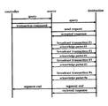
図6を用いて、ブロードキャスト通信方式を用いたオブジェクトデータの通信手順を説明する。コントローラは、ユーザが選択したソースノードと、デスティネーションノードとの間の接続を行うために、ネゴシエーションを行う。ネゴシエーションには、接続を行うためのパケットを用いる。該パケットは、例えば、asynchronousブロードキャストパケットであり、パケット内のペイロードには、接続の番号を示すコネクションID が書き込まれている。上記コネクションIDによって、それぞれのノードは、コネクションを識別する。
【0110】
コントローラから、上記のネゴシエーションパケットを受け取ったソースノードは、コントローラからの送信コマンドパケットを待機する。一方、上記ネゴシエーションパケットを受け取ったデスティネーションノードは、ソースノードからの、問い合わせのasynchronousブロードキャストパケットを待機する。
【0111】
該問い合わせのasynchronousブロードキャストパケットは、ソースノードが、デスティネーションノードに対して、受信準備が整ったかどうかを問い合わせる。上記コントロールノードに対し、ソースノード、及び、デスティネーションノードは、上記ネゴシエーションパケットがブロードキャストパケットであるので、アクノリッジパケットを送出しない。
【0112】
上述のネゴシエーションが終わると、コントローラは、ソースノードに、データ送信のためのコマンドパケットを送信する。ソースノードは、上記コマンドパケットがブロードキャストパケットであるので、コントロールノードに対し、アクノリッジパケットを送出しない。
【0113】
上記コマンドパケットを受信したソースノードは、デスティネーションノードに対して、問い合わせのasynchronousブロードキャストパケットを送信する。該問い合わせパケットには、上述のコネクションIDが書き込まれている。デスティネーションノードは、上記問い合わせパケットがブロードキャストパケットであるので、ソースノードに対し、アクノリッジパケットを送出しない。
【0114】
上記問い合わせパケットを受信すると、デスティネーションノードは、上記問い合わせパケットに書かれているコネクションIDと、上述のネゴシエーションによるコネクションIDとを照合して、該問い合わせパケットが同じコネクションのソースノードからのパケットであるかどうかを判別する。
【0115】
上記問い合わせパケットが同じコネクションの場合、デスティネーションノードは、上記問い合わせパケットと同一のコネクションIDと、データ受信用のバッファの容量と、を書き込んだacceptedレスポンスパケットを、asynchronousブロードキャストで送出する。ソースノードは、上記レスポンスパケットがブロードキャストパケットであるので、デスティネーションノードに対し、アクノリッジパケットを送出しない。
【0116】
データ転送の際に、ソースノードは、コントローラから指示された、デスティネーションノードのノードオフセットに対してライトトランザクションを行なう。該ライトトランザクションは、Asynchronousブロードキャストパケットを使用して行われる。本実施の形態では、デスティネーションノードは、上記ライトトランザクションごとに、ソースノードに対し、図3に示すアクノリッジパケットを送出し、デスティネーションノードがbusy状態の場合、ソースノードはリトライを行なうことで、データ転送の確実性を保証するようになっている。その際、ソースノードは、図4、または、図5で示される、リトライ動作を行なうことにより、上述のデッドロックの発生を防止する。
【0117】
ソースノードは、送信が行なわれるオブジェクトデータ(例えば、静止画像、動画像、テキスト等)を分割(segmentation)してデータを送信する。分割されたデータを、segment dataと称する。segment dataの送信は、1度のブロードキャストトランザクションにて行なわれる。該segment dataのデータ量は、例えば、データを受信するノードの(不図示の)FIFO メモリの容量によって定まるようになっている。
【0118】
ソースノードは、上記segment dataを、asynchronousブロードキャストパケットを使用して送信する。一つのsegment dataを含むasynchronousブロードキャストパケットを、segment パケットと称する。
【0119】
segment パケットには、上述のコネクションIDと、上記segment dataの順番を示すシークエンス番号とが書かれている。該パケットを受信したデスティネーションノードは、segment パケット内に書かれているコネクションIDと、事前にコントローラによって通知されているコネクションIDとの照合を行なう。
【0120】
segment パケット内に書かれているコネクションIDと、事前にコントローラによって通知されているコネクションIDとが一致した場合、デスティネーションノードは、該パケットを受け取り、該パケットと同一のコネクションIDと受信データ中のシークエンス番号とを書き込んだ不図示のレスポンスパケットを、asynchronousブロードキャストを用いて送信する。
【0121】
ソースノードは、受信したパケットのコネクションIDによって、自ノードへのパケットを識別する。上述のレスポンス動作は、一つのsegment dataの授受に伴い生ずることになる。
【0122】
上述したように、データ授受に先立って、ソースノードからデスティネーションノードへ問い合わせパケットが送信される。デスティネーションノードは、該問い合わせに対するレスポンスパケットを用いて、デスティネーションノード自身が有しているバッファのバッファサイズを通知する。
【0123】
上述した例では、1度のsegment dataの送信に伴って、レスポンスパケットの送信が発生しているが、デスティネーションノードが有する上述のバッファがsegment dataによって満たされた後に、デスティネーションノードがレスポンスパケットの送信を行なうように構成しても良い。このように構成した場合には、デスティネーションノードの行なうレスポンス動作の回数を削減できるので、デスティネーションノードを簡略化できる効果がある。
【0124】
本実施の形態のデスティネーションノードは、i 番目に受信したsegment パケットのシークエンス番号と、(i+1) 番目に受信したsegment パケットのシークエンス番号とを比較して、データの不整合を監視する。デスティネーションノードは、シークエンス番号に不整合が検出された場合には、再送要求を示すレスポンスパケットを送出することにより、ソースノードに再度segment dataを要求することができる。また、再送要求を示すレスポンスパケットは、再送要求の生じたシークエンス番号を指定できるようになっている。
【0125】
一方、ソースノードは、segment パケットを送信した後、デスティネーションノードからのレスポンスを待機する。上述したように、デスティネーションノードからはコネクションIDと、シークエンス番号とが書かれたレスポンスパケットが、Asynchronousブロードキャストパケットで送信される。
【0126】
ブロードキャストパケットで送信されるレスポンスパケットには、上記コネクションIDが書き込まれている。この値が、目的のデスティネーションノードとのコネクションを示すコネクションIDと一致した場合、該パケットはレスポンスパケットである。該レスポンスパケットを受信するとソースノードは、シークエンス番号をインクリメントし、次のsegment パケットを同様に送信する。上述の手順を繰り返すことにより、ソースノードは、データ転送を行なう。
【0127】
ソースノードが、デスティネーションノードからのレスポンスを待機する時間は、あらかじめ定められており、この周期をレスポンス周期と称する。i 番目のsegment パケットを送信した後、レスポンス周期を越えてもレスポンスが受信できない場合、ソースノードは、上記i 番目のsegment パケットと同一のsegment パケットを再送する。
【0128】
また、上述したような、デスティネーションノードからの再送要求レスポンスを受信した場合、ソースノードは、該レスポンスパケットにて指定されたシークエンス番号のsegment パケットを送信する。本実施の形態では、上記手順により、バスリセットの発生や何らかのエラーの発生により、データ転送が中断した場合にも、データ転送の復帰が容易に行なえるといった効果がある。
【0129】
全てのsegment パケットを送信することによって、データ転送が終了すると、ソースノードは、segment end を示すブロードキャストパケットを送出する。このパケットを受け取ったコントローラは、コネクションIDを解放して、データ転送が終了する。
【0130】
本実施の形態では、segment end を受信したコントローラが、明示的にコネクションIDを解放している。しかしながら、segment end を示すパケットがブロードキャストパケットであることから、該segment end パケットにより、デスティネーションノードが、データ転送の終了を検知することが可能である。このため、コネクションID、解放をデスティネーションノードが行なっても良い。
【0131】
確実にデータを転送するためには、バスリセットの発生や何らかのエラーの発生により、データ転送中が中断した場合にも、速やかに該データ転送が再開されることが望ましい。上述したように、本実施の形態では、再送要求の手順を設けることで該問題点を解決している。
【0132】
例えば、シークエンス番号がiであった時に、データ転送が中断した場合、まず、各ノードは規格で定められた手順でバスの再構築を行う。バスの再構築が完了した後、デスティネーションノードは、destination _offset、コネクションID、及び、シークエンス番号iを書き込んだ再送要求パケット(resend request)を、ブロードキャストパケットで送信する。
【0133】
データ転送の再開が可能な場合には、ソースノードは、acceptedレスポンスを返す。その後、ソースノードは受信したパケットのコネクションIDを照合し、要求されたシークエンス番号の以降、すなわち、シークエンス番号(i+1) で始まるデータ列のデータを順次ブロードキャストパケットで送信する。
【0134】
上述の手順により、ソースノード、デスティネーションノード、コントローラノードはそれぞれノードIDを考慮することなく、データ転送が中断しても、その後のデータ転送を容易に、かつ、確実に再開することができる。また、上述のように、本実施の形態では、データ転送が中断した場合にも、コントローラの制御手順が簡略化できる効果がある。
【0135】
本実施の形態においては、上記のネゴシエーションパケット、コマンドパケット、問い合わせパケット、レスポンスパケットに対しては、アクノリッジパケットを送出せず、リトライを行なわないように記述しているが、上記のパケットに対し、アクノリッジパケットを送出し、リトライを行うように構成しても良いことはいうまでもない。
【0136】
次に、図7を用いて、上述のAsynchronousブロードキャストパケットについて説明する。本実施の形態に係るAsynchronousブロードキャストパケットは、例えば、4 byte (32 bits 、以下クアッドレットと称する) を単位とするデータパケットである。
【0137】
Asynchronous パケットにおいて、最初の16 bits はdestination _IDフィールドであり、該フィールドは受信先のノードIDを示す。本実施の形態のように、ブロードキャストを行なう場合には、このフィールドの値はFFFF16である。次の6 bitsのフィールドは、トランザクション・ラベル(tl)フィールドであり、各トランザクション固有のタグである。次の2 bitsのフィールドは、リトライ(rt)コードであり、パケットがリトライを試みるかどうかを指定する。
【0138】
次の4 bitsのフィールドは、トランザクションコード(tcode) である。tcode は、パケットのフォーマットや、実行しなければならないトランザクションのタイプを指定する。本実施の形態においては、例えば、この値が00012 である、データブロックの書き込みリクエストのトランザクションを用いる。
次の4 bitsのフィールドは、プライオリティ(pri) フィールドであり、優先順位を指定する。本実施の形態においては、Asynchronousパケットを用いているので、このフィールドの値は00002 である。
【0139】
次の16 bits はsource_IDフィールドであり、送信側のノードIDを示す。次の48 bits はdestination _offsetフィールドであり、パケットの受信先ノードアドレスの、下位48 bits がこのフィールドによって指定される。本実施の形態においては、例えば、該destination _offsetの値は、後述するconnection_IDフィールドの値によって定められる。
【0140】
次の16 bits はdata_lengthフィールドであり、後述するデータフィールドの長さを、バイト単位で示している。次の16 bits はextended_tcode フィールドであり、本実施の形態に用いられるデータブロックの書き込みリクエストトランザクションにおいては、この値は000016である。
【0141】
次の32 bits はheader_CRC フィールドであり、上述したdestination _IDフィールドからextended_tcode フィールドまでを、パケットヘッダと称し、該パケットヘッダのエラー検出に用いられる。
【0142】
次の16 bits は、上述したコネクションID(connection _ID) フィールドであり、該データによってコネクションを識別する。該コネクションIDによって、(2の 16 乗) × (ノード数) のコネクションを確立することが可能である。よって、本実施の形態では、各コネクションの使用する帯域の総量が、バスの容量に達するまで、コネクション数を増すことができる。
【0143】
次の8 bitsは、プロトコルタイプ(protocol _type) フィールドであり、該ヘッダ・インフォメーションを用いたデータ授受の手順を示す。本実施の形態の授受手順には、例えば、0116の値が用いられる。次の8 bitsは、コントールフラグ(control_flags)フィールドであり、制御データが書かれる。コントールフラグフィールドの最上位ビットは、例えば、再送要求(resend _request)フラグであり、このビットの値が1の時、データの再送要求が生じていることを示す。
【0144】
次の16 bits は、シークエンス番号(sequence _number) フィールドである。上述したように、該シークエンス番号フィールドは、特定のコネクションIDにて送受信されるデータパケットに対し、連続的な値が使用される。デスティネーションノードは、該シークエンス番号フィールドによって、有意なデータの連続性を監視し、不一致が生じた場合には、ソースノードに対して再送要求を行なう。
【0145】
次の16 bits は、確認応答番号(reconfirmation _number) フィールドである。このフィールドは、上述の再送要求フラグの値が1の時のみ、意味を持つフィールドである。上述の再送要求フラグの値が1 の時、このフィールドは、再送要求が生じている開始パケットのシークエンス番号を示す。
【0146】
次の16 bits は、バッファサイズ(buffer _size) フィールドである。このフィールドには、デスティネーションノードのバッファサイズが書かれる。次の16 bits は、reservedフィールドであり、将来のために予約されている。
【0147】
次のフィールドは可変長のデータフィールドであり、該データフィールドをパケットのペイロードと称する。本実施の形態においては、該データフィールドがクアッドレットの倍数でない場合、クアッドレットに満たないビットには0が詰められる。
【0148】
次の32 bits のフィールドはdata_CRC フィールドであり、上述のheader_CRC フィールドと同様に、上述のヘッダインフォメーションと該データフィールドとのエラー検出に用いられる。なお、data_CRC フィールドは、データフィールドのみに付けられても良いことはいうまでもない。
【0149】
上述のようなパケットを受け取ったノードは、図3に示す、上述のアクノリッジパケットによって、応答を返す。また、上述のようなパケットを受け取ったノードは、図8に示すような、アクノリッジパケットを用いて、応答を返すようにしても良い。
【0150】
図8に示すアクノリッジパケットにおいて、アクノリッジパケットの最初の4 bitsはack _codeフィールドである。該フィールドによって、上述したack _busy_A 、ack _busy_B 、ack _busy_X などのコードが転送される。該ack _codeフィールドの符号化は、上述の図3に示すアクノリッジパケットと同様である。次の4 bitsのフィールドは、ack _parityフィールドであり、アクノリッジパケットのパリティチェックビットが格納される。例えば、本実施の形態では、上記ack _codeの値の1の補数が格納される。該フィールドは、上記ack _codeフィールドのエラー検出に用いられる。
【0151】
次の8 bitsのフィールドは、min _retry _periodフィールドである。該フィールドには、上述した最少リトライ周期の値が、例えば、1ミリ秒単位で格納される。例えば、該フィールドの値が0116であった時、該アクノリッジパケットを受信したノードは、上述した最少リトライ周期を、1ミリ秒に設定して、該最少リトライ周期の期間はリトライを返さないように動作する。もちろん、上記min_retry _periodフィールドの設定の単位として、1ミリ秒ではない、他の時間単位を用いることができることはいうまでもない。
【0152】
また、該フィールドを設定してアクノリッジパケットを返すノードは、自ノードの負荷状態を監視して、負荷の大きい時には上述の最少リトライ期間の値を大きく、負荷の小さい時には上述の最少リトライ期間の値を小さく設定する。
【0153】
ノードの負荷状態は、該ノードに対して行なわれたリトライの数や、該ノードに対して送信されているパケットの数、該ノードのバッファの占有状態、該ノードが有している接続の数など、様々な指標を用いることが可能である。もちろん、ノードの負荷状態を検出する指標は、上記に限定されるものではなく、負荷状態が検出できれば良いことはいうまでもない。
【0154】
さらに、上記min _retry _periodフィールドの値を0016に設定することを、特別の意味に用いることも可能である。例えば、min _retry _periodフィールドの値が0016の時には、標準(default)として最少リトライ周期を100 ミリ秒に設定する。
【0155】
もちろん、標準(default) として最少リトライ周期は、100 ミリ秒に限定されるものではなく、他の値に設定されるようになっていても良いことはいうまでもない。また、他の実施の形態として、min _retry _periodフィールドの値が0016の時には、リトライを返すノードができるだけ早くリトライを返す、いわゆる、即座のリトライ(immediately retry)を行なうように設定しても良い。
【0156】
図9は、上記の最少リトライ周期を設定する動作を示すダイアグラムである。図9(a) は、ライトリクエストを行なうソースノードと、該リクエストに対しアクノリッジパケットを返すデスティネーションノードとの間の、パケットの授受を示す動作フローであり、図9(b) は、上記デスティネーションノードの負荷状態の時間変化を示すグラフである。図9(b) において、左から右方向は上記デスティネーションノードの負荷状態を示し、上から下方向は時間経過を示す。
【0157】
図9において、上記ソースノードが第一のライトリクエスト(write request #1)を行なった時点(t1)では、上記デスティネーションノードの負荷は、比較的小さい状態である(L1)とともに、busy状態である。デスティネーションノードは、例えば、上記min _retry _periodの値を3216に設定してack _busy_X のアクノリッジパケットを返す。
【0158】
ソースノードは、該アクノリッジパケットの上記min _retry _periodの値から、最少リトライ周期を50ミリ秒に設定する。ソースノードは、最少リトライ周期の期間はリトライを行なわず、少なくとも、50ミリ秒の後にリトライを行なう(retry #1) 。図9においては、該リトライは成功し、該ライトトランザクションが完了する。
【0159】
次に、上記ソースノードが第二のライトリクエスト(write request #2)を行なった時点(t2)では、上記デスティネーションノードの負荷は、比較的大きい状態である(L2)とともに、busy状態である。デスティネーションノードは、例えば、上記min _retry _periodの値をB416に設定してack _busy_X のアクノリッジパケットを返す。
【0160】
ソースノードは、該アクノリッジパケットの上記min _retry _periodの値から、最少リトライ周期を180 ミリ秒に設定する。ソースノードは、最少リトライ周期の期間はリトライを行なわず、少なくとも、180 ミリ秒の後にリトライを行なう(retry #2)。
【0161】
上記のごとく動作することにより、本実施の形態では、アクノリッジパケット送出するノードが、動的に最少リトライ周期を設定することにより、通信が確実に行なわれることを保証するとともに、バスが混雑した場合にも、busy状態の頻発を防止し、デッドロックの発生を防ぐことのできる通信システムを提供できる効果がある。また、上記のごとく動作することにより、本実施の形態では、動的に上記最少リトライ周期を設定できるので、通信リソースを適切に配分でき、リトライを行なうノードが通信路を占有しないので、通信効率を向上させることができる効果がある。
【0162】
(本発明の他の実施形態)
本発明は複数の機器(例えば、ホストコンピュータ、インタフェース機器、リーダ、プリンタ等)から構成されるシステムに適用しても1つの機器からなる装置に適用しても良い。
【0163】
また、上述した実施形態の機能を実現するように各種のデバイスを動作させるように、上記各種デバイスと接続された装置あるいはシステム内のコンピュータに対し、上記実施形態の機能を実現するためのソフトウェアのプログラムコードを供給し、そのシステムあるいは装置のコンピュータ(CPUあるいはMPU)に格納されたプログラムに従って上記各種デバイスを動作させることによって実施したものも、本発明の範疇に含まれる。
【0164】
また、この場合、上記ソフトウェアのプログラムコード自体が上述した実施形態の機能を実現することになり、そのプログラムコード自体、およびそのプログラムコードをコンピュータに供給するための手段、例えばかかるプログラムコードを格納した記憶媒体は本発明を構成する。かかるプログラムコードを記憶する記憶媒体としては、例えばフロッピーディスク、ハードディスク、光ディスク、光磁気ディスク、CD−ROM、磁気テープ、不揮発性のメモリカード、ROM等を用いることができる。
【0165】
また、コンピュータが供給されたプログラムコードを実行することにより、上述の実施形態の機能が実現されるだけでなく、そのプログラムコードがコンピュータにおいて稼働しているOS(オペレーティングシステム)あるいは他のアプリケーションソフト等の共同して上述の実施形態の機能が実現される場合にもかかるプログラムコードは本発明の実施形態に含まれることは言うまでもない。
【0166】
さらに、供給されたプログラムコードがコンピュータの機能拡張ボードやコンピュータに接続された機能拡張ユニットに備わるメモリに格納された後、そのプログラムコードの指示に基づいてその機能拡張ボードや機能拡張ユニットに備わるCPU等が実際の処理の一部または全部を行い、その処理によって上述した実施形態の機能が実現される場合にも本発明に含まれることは言うまでもない。
【0167】
【発明の効果】
本発明によれば、バスが混雑した場合にも、busy状態の頻発を防止することができ、デッドロックの発生を防ぐことができる。
【図面の簡単な説明】
【図1】本発明の実施の形態のデータ通信システムの構成を表すブロック図である。
【図2】本発明の実施の形態で使用されるasynchronousパケットの一般的な構造を示す図である。
【図3】本発明の実施の形態で使用されるアクノリッジパケットの構造を示す図である。
【図4】本発明の実施の形態におけるシングルフェイズリトライにおける送信ノードの動作の一例を示す状態遷移図である。
【図5】本発明の実施の形態におけるデュアルフェイズリトライにおける送信ノードの動作の一例を示す状態遷移図である。
【図6】本発明の実施の形態のブロードキャスト通信を用いたデータ転送手順のダイアグラムを示す図である。
【図7】本発明の実施の形態のブロードキャスト通信に用いられるデータパケットの構造を示す図である。
【図8】本発明の実施の形態に用いられる最少リトライ周期を設定するためのアクノリッジパケットの構造を示す図である。
【図9】本発明の実施の形態における最少リトライ周期を設定する動作のダイアグラムを示す図である。
【図10】従来のパケット受信ノードの動作を示す状態遷移図である。
【図11】従来のパケット送信ノードの動作を示す状態遷移図である。
【符号の説明】
10 computer
12 演算処理装置 (MPU)
14 第一の1394インターフェイス
16 キーボードなど第一の操作部
18 第一のデコーダ
20 CRTディスプレイなどの表示装置
22 ハードディスク
24 第一のメモリ
26 PCIバスなどのコンピュータ内部バス
28 VCR
30 撮像光学系
32 A/D変換器
34 ビデオ処理部
36 圧縮伸長回路
38 第二のメモリ
40 第三のメモリ
42 第一のデータセレクタ
44 第二の1394インターフェイス
46 第一のメモリ制御回路
48 第二のメモリ制御回路
50 システムコントローラ
52 第二の操作部
54 電子ビューファインダ
56 D/A変換器
58 記録部
60 プリンタ
62 第三の1394インターフェイス
64 第二のデータセレクタ
66 第三の操作部
68 プリンタコントローラ
70 第二のデコーダ
72 第四のメモリ
74 画像処理部
76 ドライバ
78 プリンタヘッド[0001]
BACKGROUND OF THE INVENTION
The present inventionA source node that transmits the transmitted data, and a destination node that receives the transmitted dataData communication systemToSekiDo.
[0002]
[Prior art]
Among personal computer peripherals, hard disks and printers are the most frequently used. These peripheral devices have general-purpose interfaces for small computers, such as SCSI, which is a typical digital interface (hereinafter referred to as digital I / F). Data communication is performed between computers.
[0003]
In addition, recording and playback devices such as digital cameras and digital video cameras are one of the peripheral devices as input means to a personal computer (hereinafter referred to as “PC”), and in recent years, images such as still images and videos taken with digital cameras and video cameras have been recorded. The technology in the field of importing to a PC, storing it on a hard disk, or editing with a PC and then printing with a printer is advancing, and the number of users is increasing.
[0004]
When the captured image data is output from a PC to a printer or hard disk, data communication is performed via the above SCSI, etc., and in such a case, a large amount of information such as image data is sent. For this reason, such a digital I / F is required to have a high transfer data rate and versatility.
[0005]
AV devices such as digital VTRs, TVs, tuners, etc., personal computers (hereinafter referred to as PCs), etc. are connected to each other using an IEEE1394 serial bus (hereinafter referred to as 1394), and digital video signals, digital Communication systems that transmit and receive audio signals and the like have been proposed. This system is known as the IEEE1394 Standard for High Performance Serial Bus standard.
[0006]
In the 1394 standard, asynchronous data transfer and synchronous data transfer are defined. Asynchronous data transfer provides a packet transfer protocol that transmits a variable-length data packet to a specified address and returns a recognition packet (acknowledge packet). In synchronous (hereinafter referred to as isochronous) data transfer, a packet transfer protocol is provided that transfers variable-length packets at regular time intervals.
[0007]
In the asynchronous data transfer of the 1394 standard, when an arbitrary node cannot cope with a packet due to a large number of processes, a retry procedure for returning a response informing that in the return packet is performed. Is defined.
[0008]
In the retry procedure, a retry code may be added to an arbitrary return packet informing that a request packet or a response packet has been received. The state transition diagram shown in FIG. 10 shows an example of behavior when a receiving node in 1394 processes a packet received from another node.
[0009]
When the node in FIG. 10 receives an Initialize or Reset control request from the node controller, the node transits from any other state except the ISR0 state to the ISR0 state. In the ISR0 state, use of communication resources is permitted, and the node waits to receive the first packet from another node. When an asynchronous (hereinafter referred to as asynchronous) packet is received in the ISR0 state, the node returns response data indicating reception having an appropriate value.
[0010]
When communication resources are unavailable, the node transitions from the ISR state to the ISR1 state. At this time, the node is said to be busy. In this case, the node is in a state where it cannot accept the first packet from another node. When an asynchronous packet is received in the ISR1 state, the node returns reception response data of ack_busy_X. If use of communication resources is permitted in the ISR1 state, the node changes to the ISR0 state and is not in the busy state.
[0011]
The state transition diagram shown in FIG. 11 shows an example of the behavior when the transmitting node in 1394 receives busy after transmitting a main packet to another node. Further, when the node shown in FIG. 11 receives an Initialize or Reset transaction control packet from the node controller, the node transits from another state to the OSR0 state.
[0012]
At this time, the node is ready to transmit packets to other nodes. When the node receives a packet other than ack_busy_A, ack_busy_B, and ack_busy_X in the OSR0 state, the node transmits the packet and does not need to retry. When the node receives the ack_busy_A, ack_busy_B, and ack_busy_X packets in the OSR0 state, the node recognizes that the destination node is in the busy state. In this case, since a retry is required, the node transits to the OSR1 state.
[0013]
When in OSR1 state, the node has a pending retry that must be resolved and must resolve the retry before sending any other packet. At this time, the node performs a retry by designating a retry code as retry_X. In the OSR1 state, the so-called retry limit that does not exceed the so-called retry limit, which is the upper limit of the number of times the node will retry, is placed in a so-called retry queue that is a queue of retry packets. If not, the node remains in the OSR1 state.
[0014]
When the node does not exceed the retry limit described above in the OSR1 state and the retry packet is placed in the retry queue, the node transits from the OSR1 state to the OSR0 state.
[0015]
Further, when the node receives a packet other than one of ack_busy_A, ack_busy_B, and ack_busy_X in the OSR1 state, the packet from the node has already been transmitted, and transitions from the OSR1 state to the OSR0 state.
[0016]
Furthermore, when the node exceeds the retry limit described above in the OSR1 state and performs a retry, this communication fails, and the node transits from the OSR1 state to the OSR0 state.
[0017]
As described above, when the node that received the packet is busy and cannot receive the packet, the receiving node informs the node that transmitted the packet that the receiving node is busy, and the transmitting node will retry later. Do it. At the time of retry, a retry code is added to the packet and transmitted.
[0018]
There are two types of retries: single phase retry and dual phase retry. Single phase retry is a relatively simple operation, and is repeated until reception is successful or the retry limit is exceeded. The retry operation describes single phase retry.
[0019]
In the case of dual phase retry, the received packet is divided into groups A and B, and a retry operation is performed. In the case of dual phase retry, when the receiving node is busy, the receiving node responds with an acknowledge packet of ack_busy_A or ack_busy_B.
[0020]
Thereafter, when the transmission node performs a retry, the transmission node uses retry_A when receiving ack_busy_A immediately before and uses retry_B when receiving ack_busy_B immediately before.
[0021]
When the receiving node receives a retry of retry_A, it assigns ack_busy_B to a packet from another node. When all retry_A retries have been accepted, the receiving node accepts retry_B retries and assigns ack_busy_A to other received packets. The above process is repeated, and the processes of the A group and the B group proceed alternately.
[0022]
In the dual phase retry, a timeout is used to determine whether all retries of retry_A have been completed. A transmitting node that uses dual phase retry must retry every four fairness intervals (as defined in the IEEE1394 standard) until the retry timeout expires.
[0023]
The receiving node assumes that all retries of retry_A are transmitted during the lapse of four fairness intervals in a state where all retries of retry_A are not busy. A similar timeout applies to retry_B. Therefore, if the transmitting node cannot retry during the four fairness interval periods, the communication fails.
[0024]
When a transmitting node that implements only single-phase retry receives an acknowledge code of either ack_busy_X, ack_busy_A, or ack_busy_B, it must now retry using the retry code of retry_X. ing.
[0025]
Also, the receiving node that implements the dual phase retry accepts the retry_X retry when the retry phase when the retry_X retry is received is completed.
[0026]
As described above, in 1394 asynchronous communication, it is guaranteed that communication is reliably performed by retry. Conventionally, a data transfer method using data exchange by a write transaction using this asynchronous communication has been proposed.
[0027]
[Problems to be solved by the invention]
However, in the conventional data transfer method using the asynchronous write transaction, it is not specified how long to wait after ack_busy_X, ack_busy_A, ack_busy_B, etc. return.
[0028]
Therefore, when a transfer is performed by a combination of a reception node having a low processing speed and a high-speed transmission node, when the bus is congested, the high-speed transmission node is frequently retried and the processing speed is low. It is expected that the receiving node's buffer will always be filled.
[0029]
In this case, the transfer of ack_busy_X, ack_busy_A, and ack_busy_B from the receiving node frequently occurs, so that the transmitting node cannot transmit the next packet, so-called deadlock occurs. was there.
[0030]
In the case of a data transfer method using broadcast communication, there is a problem that retry cannot be performed and it is not guaranteed that communication is performed reliably.
[0031]
The present invention, BaAn object is to prevent the occurrence of deadlocks by preventing frequent occurrences of ack_busy_X, ack_busy_A, ack_busy_B, etc. even when the network is congested.
[0032]
[Means for Solving the Problems]
A data communication system according to the present invention includes a source node that transmits transmitted data and a destination node that receives the transmitted data, and the source node has not received the transmitted data normally. In this case, the destination node has a function of prohibiting retransmission processing of the transmitted data until a predetermined time elapses.When the load state of the destination node is the first load state, the predetermined time is changed to the first time and notified to the source node, and the load state of the destination node is the first load state. In the case of the second load state that is larger than the load state,The predetermined timeChange to a second time longer than the first timeIt has a function of notifying the source node.
[0041]
DETAILED DESCRIPTION OF THE INVENTION
Hereinafter, an embodiment of the present invention will be described with reference to FIG. In FIG. 1, 10 is a computer, 12 is a processing unit (MPU), 14 is a first 1394 interface, 16 is a first operation unit such as a keyboard, 18 is a first decoder, 20 is a CRT display, etc. A display device, 22 is a hard disk, 24 is a first memory, the internal memory of the
[0042]
28 is a VCR, 30 is an imaging optical system, 32 is an analog-digital (A / D) converter, 34 is a video processing unit, 36 is a compression / decompression circuit, 38 is a second memory, and 40 is a third memory. , 42 is a first data selector, 44 is a second 1394 interface, 46 is a first memory control circuit, 48 is a second memory control circuit, 50 is a system controller, 52 is a second operation unit, 54 is a viewfinder, 56 is a D / A converter, and 58 is a recording unit.
[0043]
Further, 60 is a printer, 62 is a third 1394 interface, 64 is a second data selector, 66 is a third operation unit, 68 is a printer controller, 70 is a second decoder, and 72 is a fourth memory. 74 is an image processing unit, 76 is a driver, and 78 is a printer head.
[0044]
The
[0045]
In the present embodiment, for example, the
[0046]
The
[0047]
The 1394 interface 14 receives an image signal transferred on the 1394 serial bus, and transmits an image signal recorded in the
[0048]
The 1394 interface 14 transmits command data to other devices connected on the 1394 serial bus. The 1394 interface 14 transfers a signal transferred on the 1394 serial bus to another 1394 node.
[0049]
The operator causes the
[0050]
In the present embodiment, for example, the
[0051]
In general, the compression processing circuit is provided independently for YC, but here, for the sake of simplification of explanation, an example of compression processing in YC time division is shown. Next, shuffling is performed for the purpose of making the image data resistant to transmission path errors. The purpose of this processing is to convert a burst error, which is a continuous code error, into a random error, which is a discrete error that can be easily corrected and interpolated. In addition, if importance is attached to the purpose of uniforming the bias in the generation of information amount due to density in the image screen, if this processing step is brought before the compression processing, a variable length code such as run length can be added. Convenient when used.
[0052]
In response to this, data identification (ID) information for restoring data shuffling is added. The ID added by the ID adding operation is used as auxiliary information in the reverse compression processing (information amount expansion processing) at the time of reproduction together with the mode information of the system recorded at the same time. In order to reduce errors during reproduction of these data, error correction (ECC) information is added.
[0053]
Up to the addition of such a redundant signal is processed for each independent recording area corresponding to information such as video and audio. As described above, the image signal to which the ID information and the ECC information are added is recorded on a recording medium such as a magnetic tape by the
[0054]
On the other hand, the image data multiplexed by the video processing unit 34 is digital-analog converted by the D /
[0055]
The image data multiplexed by the video processing unit 34 is output to the third memory 40 and temporarily stored. The operation of the second memory 38 and the third memory 40 described above is controlled by the
[0056]
The
[0057]
The second 1394 interface 44 receives command data for controlling the
[0058]
[0059]
In the present embodiment, for example, the printer 60 operates as an image printout device. The third 1394
[0060]
The received image data is input to the
[0061]
On the other hand, the received command data is input to the
[0062]
As described above, the first to third 1394 interfaces 14, 44, 62 according to the present embodiment each constitute a 1394 serial bus node. The first 1394 interface 14 operates as a control node or controller, the second 1394 interface 44 operates as a source node of image data, and the third 1394
[0063]
The command packet or the response packet according to the present embodiment is transmitted / received by an Asynchronous packet, for example. The asynchronous packet is, for example, a data packet in units of 4 bytes (32 bits, hereinafter referred to as quadlet).
[0064]
FIG. 2 is a diagram showing the structure of a general asynchronous packet. In FIG. 2, the first 16 bits are a destination_ID field, which indicates a destination node ID. The next 6 bits field is a transaction label (tl) field, which is a tag unique to each transaction.
[0065]
The next 2 bits field is a retry (rt) code, which specifies whether the packet will retry. In addition, this field designates the above-described retry protocol for the packet reception node shown in FIG. Table 1 below shows an example of encoding the retry code.
[0066]
[Table 1]
If the node that transmits the packet does not support the optional dual phase retry described above, retry_X must be used as the value of the field.
[0068]
The next 4 bits field is the transaction code (tcode). tcode specifies the format of the packet and the type of transaction that must be performed. In the present embodiment, for example, this value is 0001.2The data block write request transaction is used.
[0069]
The next 4 bits field is a priority (pri) field, which specifies the priority. In this embodiment, since an Asynchronous packet is used, the value of this field is 0000.2It is.
[0070]
The next 16 bits are a source_ID field, which indicates a node ID on the transmission side. The next 48 bits are packet type specific information, which is a field in which information specific to the type of Asynchronous packet is stored.
[0071]
In the case of a so-called request packet such as a data block write request, read request, or lock request as in this embodiment, this field is a destination_offset field, and the lower 48 bits of the receiving node address of the packet are Specified by field.
[0072]
In the case of a response packet for write, read, and lock requests, the field is divided into an upper 4 bits rcode field and a lower 44 bits reserved field. The rcode field stores the response code for the request. In the reserved field, for example, 0000000000016The value of is filled.
[0073]
The next 32 bits are packet type specific quadlet data, which is a field in which data specific to the type of Asynchronous packet is stored. This field may not exist depending on the type of packet.
[0074]
For example, this field does not exist for a packet without a data payload. Further, in the case of a packet having a data quadlet payload, this field is a quadlet_data field and
[0075]
In the case of a packet having a data block, the field is divided into a data_length field of upper 16 bits and an extended_tcode field of lower 16 bits. The data_length field stores the data length of a data block to be described later.
[0076]
The data length stored in the data_length field is indicated in units of bytes (8 bits), for example. The extended_tcode field has meaning only in the case of a lock request or lock response packet, and in the case of a packet other than a lock request or lock response, as in the case of a write request packet used in this embodiment, For example, 000016The value of is stored.
[0077]
The next 32 bits are the header_CRC field. The above-mentioned destination_ID field to packet type specific quadlet data is called a packet header, and the header_CRC field is used for error detection of the packet header.
[0078]
The next field is the data block. The data block includes a data block quadlets and a data_CRC field.
[0079]
The data block quadlet may be referred to as a data block payload or a data field. The data block quadlet exists in all data block packets, and usually variable-length data is stored. When variable length data is stored, the data_length field described above indicates the data length of the data block quadlet.
[0080]
In the present embodiment, the data quadlet block is filled with a value of 0 in bits that are less than a multiple of the quadlet. In other words, when the data length stored in the data_length field is indicated in units of bytes (8 bits) and the value of the data_length field is not a multiple of 4, the data quadlet block is filled with the quadlet. 0016Filled with value data.
[0081]
The next 32-bit field is a data_CRC field, which is used for error detection of the data block quadlet as in the header_CRC field described above.
[0082]
The receiving node that receives the packet as described above returns a response by an acknowledge packet. Since the acknowledge packet has a length of exactly 1 byte (8 bits), it can be easily distinguished from other packets. The acknowledge packet is also referred to as an ack packet or an ack packet. FIG. 3 is a diagram showing the structure of the acknowledge packet.
[0083]
The first 4 bits of the acknowledge packet are an ack_code field. By this field, the codes such as ack_busy_A, ack_busy_B, and ack_busy_X described above are transferred. An example of encoding of the ack_code field is shown in Table 2.
[0084]
[Table 2]
The next 4 bits field is an ack_parity field in which the parity check bit of the acknowledge packet is stored. For example, in this embodiment, 1's complement of the value of the ack_code is stored. This field is used for error detection of an acknowledge packet.
[0086]
The state transition diagram shown in FIG. 4 shows an example of the behavior when the transmitting node in the present embodiment, which implements only single phase retry, receives busy after transmitting a packet to another node.
[0087]
When the node shown in FIG. 4 receives an Initialize or Reset transaction control packet from the node controller, the node transits from another state to the OSR0 state. At this time, the node is ready to transmit packets to other nodes. When the node receives a packet other than ack_busy_A, ack_busy_B, and ack_busy_X in the OSR0 state, the node transmits the packet and does not need to retry.
[0088]
When the node receives ack_busy_A, ack_busy_B, ack_busy_X packets in the OSR0 state, the destination node is in the busy state.Whenrecognize. In this case,Lee'sAs the need arises, the node transitions to the OSR1 state.
[0089]
When in OSR1 state, the node has a pending retry that must be resolved and must resolve the retry before sending any other packet. At this time, the node performs a retry by designating a retry code as retry_X.
[0090]
In the OSR1 state, the so-called retry limit that does not exceed the so-called retry limit, which is the upper limit of the number of times the node will retry, is placed in a so-called retry queue that is a queue of retry packets. If not, the node remains in the OSR1 state.
[0091]
In the OSR1 state, a minimum retry period is set. The above minimum retry lap when in OSR1 statePeriodThere will be no transition to the OSR0 state until the time has elapsed.
[0092]
When the node does not exceed the retry limit described above in the OSR1 state and the retry packet is placed in the retry queue, the node transits from the OSR1 state to the OSR0 state. In addition, when the node receives a packet other than one of ack_busy_A, ack_busy_B, and ack_busy_X in the OSR1 state, the packet from the node has already been transmitted, and transits from the OSR1 state to the OSR0 state..
[0093]
Furthermore, when the node exceeds the retry limit described above in the OSR1 state and performs a retry, this communication fails, and the node transits from the OSR1 state to the OSR0 state.
[0094]
The state transition diagram of FIG. 5 shows an example of the behavior when the transmitting node according to the present embodiment, which implements the optional dual phase retry, receives busy after transmitting a packet to another node.
[0095]
When the node shown in FIG. 5 receives the Initialize or Reset transaction control packet from the node controller, the node transits from another state to the ODR0 state. At this time, the node is ready to transmit a packet to another node, sets the above retry code to retry_1, and waits. In the case of the ODR0 state, if the node receives an acknowledge packet other than ack_busy_A, ack_busy_B, and ack_busy_X after transmitting the packet, the packet has already been transmitted, and the node does not need to respond.
[0096]
When the ACK_busy_A or ack_busy_B acknowledge packet is received in the ODR0 state, the receiving node is a dual phase retry node and in the busy state. At this time, the node retries the packet as a dual phase retry.
[0097]
When ack_busy_A is received in the ODR0 state, the retry phase is A, and the node transits to the ODR1 state. When ack_busy_B is received in the ODR0 state, the retry phase is B, and the node transitions to the ODR2 state.
[0098]
When the ACK_busy_X acknowledge packet is received in the ODR0 state, the receiving node is a single phase retry node and is in the busy state. At this time, the node retries the packet as a single phase retry. When ack_busy_X is received in the ODR0 state, the node transits to the ODR3 state.
[0099]
When in the ODR1 state, the node is in retry phase A and has pending retries that must be resolved. In the ODR1 state, a minimum retry period is set. During the ODR1 state, during the period until the minimum retry period elapses, no retry is performed and the ODR1 state remains.
[0100]
In the ODR1 state, the node sets a retry code to retry_A and performs a retry. When the node receives an acknowledge packet in the ODR1 state, if the acknowledge code is ack_busy_A and the above four fairness interval timeout periods have not elapsed, the node remains in the ODR1 state. Repeat retry.
[0101]
When an acknowledge packet including an acknowledge code other than ack_busy_A or ack_busy_B is received in the ODR1 state, the packet has already been transmitted, and the node transits to the ODR0 state. Further, when the above-described timeout period has elapsed, the node has failed to transmit, and again transitions to the ODR0 state.
[0102]
When in the ODR2 state, the node is in retry phase B and has pending retries that must be resolved. In the ODR2 state, a minimum retry period is set. During the ODR2 state, during the period until the minimum retry period elapses, no retry is performed and the ODR2 state remains.
[0103]
In the ODR2 state, the node performs a retry by setting the retry code to retry_B. When the node receives an acknowledge packet in the ODR2 state, if the acknowledge code is ack_busy_B and the four fairness interval timeout periods described above have not elapsed, the node remains in the ODR1 state, Repeat retry.
[0104]
When an acknowledge packet including an acknowledge code other than ack_busy_A or ack_busy_B is received in the ODR2 state, the packet has already been transmitted, and the node transits to the ODR0 state. Further, when the above-described timeout period has elapsed, the node has failed to transmit, and again transitions to the ODR0 state.
[0105]
When in the ODR3 state, the node performs a single phase retry. In the ODR3 state, a minimum retry period is set. During the ODR3 state, during the period until the minimum retry period elapses, no retry is performed and the ODR3 state remains. In the ODR3 state, the node sets a retry code to retry_ and performs a retry.
[0106]
When the node receives an acknowledge packet in the ODR3 state, if the acknowledge code is ack_busy_ and the retry limit is not exceeded, the node remains in the ODR3 state and repeats the retry.
[0107]
When an acknowledge packet including an acknowledge code other than ack_busy_X is received in the ODR3 state, the packet has already been transmitted, and the node transits to the ODR0 state. If the retry limit is exceeded, the node has failed to transmit and transitions to the ODR0 state.
[0108]
By adopting a configuration having a predetermined retry period as described above, the transmitting node according to the present embodiment ensures that communication is performed reliably, and even when the bus is congested, the transmitting node in the busy state Frequent occurrences can be prevented and the occurrence of deadlocks can be prevented. Further, a communication system that can prevent the occurrence of a deadlock can be configured by using the transmission node as a source node of the present embodiment and performing a write transaction with the node.
[0109]
The object data communication procedure using the broadcast communication method will be described with reference to FIG. The controller determines the source node selected by the user and the destination.NnoNegotiate to establish a connection with the node. For the negotiation, a packet for connection is used. The packet is, for example, asynchronous broadcastTopaConnection I indicating the connection number in the payload in the packet.D ButHas been written. Each node identifies a connection by the connection ID.
[0110]
The source node that has received the negotiation packet from the controller waits for a transmission command packet from the controller. On the other hand, the destination node that has received the negotiation packet waits for an inquiry asynchronous broadcast packet from the source node.
[0111]
In the asynchronous broadcast packet of the inquiry, the source node inquires of the destination node whether reception preparation is complete. The source node and the destination node do not send an acknowledge packet to the control node because the negotiation packet is a broadcast packet.
[0112]
When the above negotiation is completed, the controller transmits a command packet for data transmission to the source node. Since the command packet is a broadcast packet, the source node does not send an acknowledge packet to the control node.
[0113]
Upon receiving the command packet, the source node transmits an inquiry asynchronous broadcast packet to the destination node. In the inquiry packet, the above-mentioned connection ID is written. Since the inquiry packet is a broadcast packet, the destination node does not send an acknowledge packet to the source node.
[0114]
When the inquiry packet is received, the destination node compares the connection ID written in the inquiry packet with the connection ID by the negotiation described above, and the inquiry packet is a packet from the source node of the same connection. Determine whether or not.
[0115]
When the inquiry packet is the same connection, the destination node transmits an accepted response packet in which the same connection ID as the inquiry packet and the capacity of the data reception buffer are written by asynchronous broadcasting. Since the response packet is a broadcast packet, the source node does not send an acknowledge packet to the destination node.
[0116]
At the time of data transfer, the source node performs a write transaction for the node offset of the destination node instructed by the controller. The light transaction is performed using an Asynchronous broadcast packet. In this embodiment, the destination node sends the acknowledge packet shown in FIG. 3 to the source node for each write transaction, and when the destination node is busy, the source node performs a retry, The certainty of data transfer is guaranteed. At that time, the source node performs the retry operation shown in FIG. 4 or 5 to prevent the occurrence of the above-described deadlock.
[0117]
The source node segments the object data (for example, still image, moving image, text, etc.) to be transmitted and transmits the data. The divided data is referred to as segment data. The segment data is transmitted in one broadcast transaction. The amount of segment data is determined by, for example, the capacity of a FIFO memory (not shown) of a node that receives the data.
[0118]
The source node transmits the segment data using an asynchronous broadcast packet. An asynchronous broadcast packet including one segment data is called a segment packet.
[0119]
In the segment packet, the connection ID described above and a sequence number indicating the order of the segment data are written. The destination node that has received the packet collates the connection ID written in the segment packet with the connection ID notified by the controller in advance.
[0120]
When the connection ID written in the segment packet matches the connection ID notified in advance by the controller, the destination node receives the packet, and the same connection ID as the packet and the received data A response packet (not shown) in which the sequence number is written is transmitted using asynchronous broadcast.
[0121]
The source node identifies the packet to its own node by the connection ID of the received packet. The above-described response operation occurs when one segment data is exchanged.
[0122]
As described above, an inquiry packet is transmitted from the source node to the destination node prior to data exchange. The destination node notifies the buffer size of the buffer held by the destination node using a response packet to the inquiry.
[0123]
In the above-described example, transmission of a response packet occurs with one transmission of segment data. However, after the above-mentioned buffer of the destination node is filled with segment data, the destination node May be configured to transmit. When configured in this manner, the number of response operations performed by the destination node can be reduced, which has the effect of simplifying the destination node.
[0124]
The destination node according to the present embodiment compares the sequence number of the i-th received segment packet with the sequence number of the (i + 1) th received segment packet and monitors data inconsistency. When inconsistency is detected in the sequence number, the destination node can request segment data from the source node again by sending a response packet indicating a retransmission request. The response packet indicating the retransmission request can specify the sequence number where the retransmission request has occurred.
[0125]
On the other hand, the source node waits for a response from the destination node after transmitting the segment packet. As described above, the response packet in which the connection ID and the sequence number are written is transmitted from the destination node as an Asynchronous broadcast packet.
[0126]
The connection ID is written in a response packet transmitted as a broadcast packet. If this value matches the connection ID indicating the connection with the target destination node, the packet is a response packet. When receiving the response packet, the source node increments the sequence number and transmits the next segment packet in the same manner. By repeating the above procedure, the source node performs data transfer.
[0127]
The time for which the source node waits for a response from the destination node is determined in advance, and this cycle is referred to as a response cycle. After transmitting the i-th segment packet, if the response cannot be received even after the response cycle is exceeded, the source node retransmits the same segment packet as the i-th segment packet.
[0128]
When receiving a retransmission request response from the destination node as described above, the source node transmits a segment packet with a sequence number specified in the response packet. In this embodiment, the above procedure has an effect that the data transfer can be easily restored even when the data transfer is interrupted due to the occurrence of a bus reset or some error.
[0129]
When data transfer is completed by transmitting all segment packets, the source node sends out a broadcast packet indicating segment end. The controller that receives this packet releases the connection ID, and the data transfer ends.
[0130]
In this embodiment, the controller that has received segment end explicitly releases the connection ID. However, since the packet indicating segment end is a broadcast packet, the destination node can detect the end of data transfer by the segment end packet. For this reason, the destination node may perform connection ID release.
[0131]
In order to transfer data reliably, it is desirable that the data transfer be resumed promptly even when the data transfer is interrupted due to the occurrence of a bus reset or some error. As described above, this embodiment solves this problem by providing a retransmission request procedure.
[0132]
For example, if the data transfer is interrupted when the sequence number is i, each node first reconstructs the bus according to the procedure defined by the standard. After the bus reconstruction is completed, the destination node transmits a retransmission request packet (resend request) in which the destination_offset, the connection ID, and the sequence number i are written as a broadcast packet.
[0133]
If the data transfer can be resumed, the source node returns an accepted response. Thereafter, the source node collates the connection ID of the received packet, and sequentially transmits the data of the data sequence after the requested sequence number, that is, the data string starting with the sequence number (i + 1) in a broadcast packet.
[0134]
By the above procedure, the source node, the destination node, and the controller node can restart the subsequent data transfer easily and reliably even if the data transfer is interrupted without considering the node ID. Further, as described above, the present embodiment has an effect that the control procedure of the controller can be simplified even when the data transfer is interrupted.
[0135]
In the present embodiment, the negotiation packet, the command packet, the inquiry packet, and the response packet are described so as not to send an acknowledge packet and do not retry, but for the above packet, It goes without saying that an acknowledge packet may be sent out and retried.
[0136]
Next, the above-described Asynchronous broadcast packet will be described with reference to FIG. The Asynchronous broadcast packet according to the present embodiment is a data packet in units of 4 bytes (32 bits, hereinafter referred to as quadlet), for example.
[0137]
In the Asynchronous packet, the first 16 bits are a destination_ID field, which indicates the node ID of the receiving destination. When broadcasting, as in this embodiment, the value of this field is FFFF16It is. The next 6 bits field is a transaction label (tl) field, which is a tag unique to each transaction. The next 2 bits field is a retry (rt) code, which specifies whether the packet will retry.
[0138]
The next 4 bits field is the transaction code (tcode). tcode specifies the format of the packet and the type of transaction that must be performed. In the present embodiment, for example, this value is 0001.2 The data block write request transaction is used.
The next 4 bits field is a priority (pri) field, which specifies the priority. In this embodiment, since an Asynchronous packet is used, the value of this field is 0000.2 It is.
[0139]
The next 16 bits are a source_ID field, which indicates a node ID on the transmission side. The next 48 bits is a destination_offset field, and the lower 48 bits of the packet receiving node address are specified by this field. In the present embodiment, for example, the value of the destination_offset is determined by the value of the connection_ID field described later.
[0140]
The next 16 bits are a data_length field, which indicates the length of the data field described later in bytes. The next 16 bits are an extended_tcode field. In the data block write request transaction used in the present embodiment, this value is 0000.16It is.
[0141]
The next 32 bits are a header_CRC field, and the above-mentioned destination_ID field to extended_tcode field are called a packet header and are used for error detection of the packet header.
[0142]
The next 16 bits are the above-described connection ID (connection_ID) field, and the connection is identified by the data. A connection of (2 to the power of 16) × (number of nodes) can be established by the connection ID. Therefore, in this embodiment, the number of connections can be increased until the total amount of bandwidth used by each connection reaches the capacity of the bus.
[0143]
The next 8 bits are a protocol type (protocol_type) field, which indicates a data exchange procedure using the header information. For example, in the transfer procedure of the present embodiment, 0116The value of is used. The next 8 bits are a control flag (control_flags) field in which control data is written. The most significant bit of the control flag field is, for example, a retransmission request (resend_request) flag. When the value of this bit is 1, it indicates that a data retransmission request has occurred.
[0144]
The next 16 bits are a sequence number (sequence_number) field. As described above, in the sequence number field, a continuous value is used for data packets transmitted and received with a specific connection ID. The destination node monitors significant continuity of data by the sequence number field, and if a mismatch occurs, makes a retransmission request to the source node.
[0145]
The next 16 bits are a confirmation number (reconfirmation_number) field. This field is meaningful only when the value of the retransmission request flag described above is 1. When the value of the above-mentioned retransmission request flag is 1, this field indicates the sequence number of the start packet for which a retransmission request has occurred.
[0146]
The next 16 bits are a buffer size (buffer_size) field. In this field, the buffer size of the destination node is written. The next 16 bits are a reserved field and are reserved for the future.
[0147]
The next field is a variable length data field, which is referred to as the packet payload. In the present embodiment, when the data field is not a multiple of a quadlet, bits that do not satisfy the quadlet are filled with 0.
[0148]
The next 32 bits field is a data_CRC field, and is used to detect an error between the header information and the data field, similarly to the header_CRC field. Needless to say, the data_CRC field may be attached only to the data field.
[0149]
The node that has received the packet as described above returns a response using the acknowledge packet shown in FIG. Further, the node that receives the packet as described above may return a response using an acknowledge packet as shown in FIG.
[0150]
In the acknowledge packet shown in FIG. 8, the first 4 bits of the acknowledge packet are an ack_code field. By this field, codes such as ack_busy_A, ack_busy_B, and ack_busy_X described above are transferred. The encoding of the ack_code field is the same as the acknowledge packet shown in FIG. The next 4 bits field is an ack_parity field in which the parity check bit of the acknowledge packet is stored. For example, in the present embodiment, 1's complement of the value of the ack_code is stored. This field is used for error detection in the ack_code field.
[0151]
The next 8 bits field is a min_retry_period field. In this field, the value of the minimum retry period described above is stored in units of 1 millisecond, for example. For example, the field value is 0116The node having received the acknowledge packet sets the above-mentioned minimum retry period to 1 millisecond and operates so as not to return a retry during the minimum retry period. Of course, as a unit for setting the min_retry_period field, it is needless to say that other time units other than 1 millisecond can be used.Yes.
[0152]
In addition, the node that sets the field and returns an acknowledge packet monitors the load state of the own node, and when the load is heavy, increases the value of the minimum retry period described above. Set to a smaller value.
[0153]
The load state of a node is the number of retries made to the node, the number of packets transmitted to the node, the buffer occupation state of the node, and the number of connections the node has. Various indicators can be used. Of course, the index for detecting the load state of the node is not limited to the above, and it is needless to say that the load state can be detected.
[0154]
Furthermore, set the value of the min_retry_period field to 0016It can also be used for a special meaning. For example, the value of the min_retry_period field is 0016In the case of, the minimum retry period is set to 100 milliseconds as the default.
[0155]
Of course, as a standard, the minimum retry period is not limited to 100 milliseconds, but may be set to other values. In another embodiment, the value of the min_retry_period field is 0016In such a case, it may be set so that a node that returns a retry returns a retry as soon as possible, that is, performs an immediate retry.
[0156]
FIG. 9 is a diagram showing an operation for setting the minimum retry period. FIG. 9A is an operation flow showing exchange of packets between a source node that performs a write request and a destination node that returns an acknowledge packet in response to the request, and FIG. 9B shows the destination. It is a graph which shows the time change of the load state of a nation node. In FIG. 9B, the left to right direction indicates the load state of the destination node, and the top to bottom direction indicates the passage of time.
[0157]
In FIG. 9, when the source node makes the first write request (write request # 1) (t1), The load on the destination node is relatively small (L1) And busy. For example, the destination node sets the value of min_retry_period to 32.16Set ack_busy_X acknowledge packet.
[0158]
The source node sets the minimum retry period to 50 milliseconds from the value of the min_retry_period of the acknowledge packet. The source node does not retry during the minimum retry period, but at least after 50 milliseconds (retry # 1). In FIG. 9, the retry is successful and the write transaction is completed.
[0159]
Next, when the source node makes a second write request (write request # 2) (t2), The load on the destination node is relatively large (L2) And busy. For example, the destination node sets the value of the min_retry_period to B416Set ack_busy_X acknowledge packet.
[0160]
The source node sets the minimum retry period to 180 milliseconds from the value of the min_retry_period of the acknowledge packet. The source node does not retry during the minimum retry period, but at least after 180 milliseconds (retry # 2).
[0161]
By operating as described above, in this embodiment, the node that sends the acknowledge packet dynamically sets the minimum retry period to ensure that communication is performed reliably, and the bus is congested. In addition, there is an effect that it is possible to provide a communication system that can prevent the occurrence of a busy state and prevent the occurrence of a deadlock. Also, by operating as described above, in the present embodiment, the minimum retry period can be dynamically set, so that communication resources can be appropriately allocated, and the node performing the retry does not occupy the communication path. There is an effect that can be improved.
[0162]
(Other embodiments of the present invention)
The present invention may be applied to a system composed of a plurality of devices (for example, a host computer, an interface device, a reader, a printer, etc.) or an apparatus composed of a single device.
[0163]
In addition, software for realizing the functions of the above-described embodiments is provided to an apparatus or a computer in the system connected to the various devices so that the various devices are operated so as to realize the functions of the above-described embodiments. What is implemented by supplying the program code and operating the various devices according to a program stored in a computer (CPU or MPU) of the system or apparatus is also included in the scope of the present invention.
[0164]
In this case, the program code of the software itself realizes the functions of the above-described embodiments, and the program code itself and means for supplying the program code to the computer, for example, the program code is stored. The storage medium constitutes the present invention. As a storage medium for storing the program code, for example, a floppy disk, a hard disk, an optical disk, a magneto-optical disk, a CD-ROM, a magnetic tape, a nonvolatile memory card, a ROM, or the like can be used.
[0165]
Further, by executing the program code supplied by the computer, not only the functions of the above-described embodiments are realized, but also the OS (operating system) or other application software in which the program code is running on the computer, etc. It goes without saying that the program code is also included in the embodiment of the present invention even when the functions of the above-described embodiment are realized jointly.
[0166]
Further, after the supplied program code is stored in the memory provided in the function expansion board of the computer or the function expansion unit connected to the computer, the CPU provided in the function expansion board or function expansion unit based on the instruction of the program code Needless to say, the present invention includes a case where the functions of the above-described embodiment are realized by performing part or all of the actual processing.
[0167]
【The invention's effect】
BookInventionAccording to theEven when the network is congested, frequent busy conditions can be prevented and deadlocks can occur.PreventYou can
[Brief description of the drawings]
FIG. 1 is a block diagram showing a configuration of a data communication system according to an embodiment of this invention.
FIG. 2 is a diagram showing a general structure of an asynchronous packet used in the embodiment of the present invention.
FIG. 3 is a diagram showing a structure of an acknowledge packet used in the embodiment of the present invention.
FIG. 4 is a state transition diagram illustrating an example of an operation of a transmission node in a single phase retry in the embodiment of the present invention.
FIG. 5 is a state transition diagram illustrating an example of an operation of a transmission node in dual phase retry in the embodiment of the present invention.
FIG. 6 is a diagram showing a data transfer procedure diagram using broadcast communication according to the embodiment of the present invention;
FIG. 7 is a diagram showing a structure of a data packet used for broadcast communication according to the embodiment of the present invention.
FIG. 8 is a diagram showing a structure of an acknowledge packet for setting a minimum retry period used in the embodiment of the present invention.
FIG. 9 is a diagram showing an operation diagram for setting a minimum retry period in the embodiment of the present invention;
FIG. 10 is a state transition diagram showing the operation of a conventional packet receiving node.
FIG. 11 is a state transition diagram showing the operation of a conventional packet transmission node.
[Explanation of symbols]
10 computer
12 processing unit (MPU)
14
16 First operation unit such as keyboard
18 First decoder
20 Display devices such as CRT displays
22 Hard disk
24 First memory
26 Computer internal bus such as PCI bus
28 VCR
30 Imaging optics
32 A / D converter
34 Video processing section
36 Compression / decompression circuit
38 Second memory
40 Third memory
42 First data selector
44
46 First memory control circuit
48 Second memory control circuit
50 System controller
52 Second control section
54 Electronic viewfinder
56 D / A converter
58 Recording section
60 Printer
62
64 Second data selector
66 Third control
68 Printer controller
70 Second decoder
72 Fourth memory
74 Image processor
76 drivers
78 Printer head
Claims (2)
前記被送信データを受信するデスティネーションノードとを有し、
前記ソースノードは、
前記被送信データが正常に受信されなかった場合において、前記被送信データの再送処理を所定時間が経過するまで禁止する機能を有し、
前記デスティネーションノードは、
前記デスティネーションノードの負荷状態が第1の負荷状態である場合においては、前記所定時間を第1の時間に変更して前記ソースノードに通知し、前記デスティネーションノードの負荷状態が前記第1の負荷状態よりも大きい第2の負荷状態である場合においては、前記所定時間を前記第1の時間よりも長い第2の時間に変更して前記ソースノードに通知する機能を有することを特徴とするデータ通信システム。A source node that transmits the transmitted data;
A destination node for receiving the transmitted data,
The source node is
In a case where the transmitted data is not normally received, a function of prohibiting retransmission processing of the transmitted data until a predetermined time elapses,
The destination node is
When the load state of the destination node is the first load state, the predetermined time is changed to the first time and notified to the source node, and the load state of the destination node is the first load state. In a case where the second load state is larger than the load state, the predetermined time is changed to a second time longer than the first time, and a function of notifying the source node is provided. Data communication system.
Priority Applications (7)
| Application Number | Priority Date | Filing Date | Title |
|---|---|---|---|
| JP11235598A JP4065466B2 (en) | 1998-04-22 | 1998-04-22 | Data communication system |
| US09/252,924 US6690648B2 (en) | 1998-02-24 | 1999-02-19 | Data communication apparatus, method, and system utilizing reception capability information of a destination node |
| DE69941313T DE69941313D1 (en) | 1998-02-24 | 1999-02-23 | Data communication system, data communication method and data communication device |
| EP99301297A EP0938218B1 (en) | 1998-02-24 | 1999-02-23 | Data communication system, method of communicating data and data communication apparatus |
| KR1019990005988A KR100311706B1 (en) | 1998-02-24 | 1999-02-23 | Data communication system, data communication method, data communication apparatus and digital interface |
| MYPI99000651A MY128864A (en) | 1998-02-24 | 1999-02-24 | Data communication system and data communication apparatus |
| CNB991032837A CN1179280C (en) | 1998-02-24 | 1999-02-24 | Data communication system, data communication method, data communication apparatus and digital interface |
Applications Claiming Priority (1)
| Application Number | Priority Date | Filing Date | Title |
|---|---|---|---|
| JP11235598A JP4065466B2 (en) | 1998-04-22 | 1998-04-22 | Data communication system |
Publications (2)
| Publication Number | Publication Date |
|---|---|
| JPH11308256A JPH11308256A (en) | 1999-11-05 |
| JP4065466B2 true JP4065466B2 (en) | 2008-03-26 |
Family
ID=14584628
Family Applications (1)
| Application Number | Title | Priority Date | Filing Date |
|---|---|---|---|
| JP11235598A Expired - Fee Related JP4065466B2 (en) | 1998-02-24 | 1998-04-22 | Data communication system |
Country Status (1)
| Country | Link |
|---|---|
| JP (1) | JP4065466B2 (en) |
Families Citing this family (1)
| Publication number | Priority date | Publication date | Assignee | Title |
|---|---|---|---|---|
| JP2006109312A (en) * | 2004-10-08 | 2006-04-20 | Fujitsu Ltd | Communication control apparatus and its method |
-
1998
- 1998-04-22 JP JP11235598A patent/JP4065466B2/en not_active Expired - Fee Related
Also Published As
| Publication number | Publication date |
|---|---|
| JPH11308256A (en) | 1999-11-05 |
Similar Documents
| Publication | Publication Date | Title |
|---|---|---|
| US6690648B2 (en) | Data communication apparatus, method, and system utilizing reception capability information of a destination node | |
| KR100294960B1 (en) | Data communication system, data communication method, and data communication apparatus | |
| US6804250B2 (en) | Data communication system and node, and method of using the system and the node | |
| US7123621B1 (en) | Data communication system, data communication method and data communication apparatus | |
| US7002964B1 (en) | Communication system, method for a communication system and controller for a communication system | |
| US6678769B1 (en) | Control apparatus and method for managing a logical connection between source and destination nodes | |
| JP4065466B2 (en) | Data communication system | |
| JP3814407B2 (en) | Data communication system, data communication apparatus, and data communication method | |
| JP3774540B2 (en) | Data transfer method, image processing system and apparatus | |
| JP4428750B2 (en) | Data communication system | |
| JP3943698B2 (en) | Data communication system and data communication apparatus | |
| JP3943697B2 (en) | Data communication system, data communication apparatus, and data communication method | |
| JP3862403B2 (en) | Data communication system and data communication apparatus | |
| JP4026979B2 (en) | Data communication system | |
| JP4143205B2 (en) | Data communication system | |
| JPH11261608A (en) | Data communication system, data communication equipment, data communication method and storage medium | |
| JPH11313091A (en) | System, device and method for data communication and storage medium | |
| JP2003309618A (en) | Communication apparatus and communication method | |
| JPH11298509A (en) | Data communication system, data communication method, data communication device and storage medium | |
| JPH11308255A (en) | System, method and device for data communication and storage medium | |
| JP2001175546A (en) | Data transfer controller, information storage medium, and electronic equipment | |
| JPH11317755A (en) | Data communication system, its method, its equipment and digital interface | |
| JP2006311614A (en) | Data communication system | |
| JPH11355319A (en) | Data communication system, method and device and digital interface |
Legal Events
| Date | Code | Title | Description |
|---|---|---|---|
| A621 | Written request for application examination |
Free format text: JAPANESE INTERMEDIATE CODE: A621 Effective date: 20050422 |
|
| A521 | Written amendment |
Free format text: JAPANESE INTERMEDIATE CODE: A523 Effective date: 20061201 |
|
| A977 | Report on retrieval |
Free format text: JAPANESE INTERMEDIATE CODE: A971007 Effective date: 20070629 |
|
| A131 | Notification of reasons for refusal |
Free format text: JAPANESE INTERMEDIATE CODE: A131 Effective date: 20070710 |
|
| A521 | Written amendment |
Free format text: JAPANESE INTERMEDIATE CODE: A523 Effective date: 20070910 |
|
| A131 | Notification of reasons for refusal |
Free format text: JAPANESE INTERMEDIATE CODE: A131 Effective date: 20071002 |
|
| A521 | Written amendment |
Free format text: JAPANESE INTERMEDIATE CODE: A523 Effective date: 20071203 |
|
| TRDD | Decision of grant or rejection written | ||
| A01 | Written decision to grant a patent or to grant a registration (utility model) |
Free format text: JAPANESE INTERMEDIATE CODE: A01 Effective date: 20071218 |
|
| A61 | First payment of annual fees (during grant procedure) |
Free format text: JAPANESE INTERMEDIATE CODE: A61 Effective date: 20080105 |
|
| R150 | Certificate of patent or registration of utility model |
Free format text: JAPANESE INTERMEDIATE CODE: R150 |
|
| FPAY | Renewal fee payment (event date is renewal date of database) |
Free format text: PAYMENT UNTIL: 20110111 Year of fee payment: 3 |
|
| FPAY | Renewal fee payment (event date is renewal date of database) |
Free format text: PAYMENT UNTIL: 20120111 Year of fee payment: 4 |
|
| FPAY | Renewal fee payment (event date is renewal date of database) |
Free format text: PAYMENT UNTIL: 20130111 Year of fee payment: 5 |
|
| FPAY | Renewal fee payment (event date is renewal date of database) |
Free format text: PAYMENT UNTIL: 20140111 Year of fee payment: 6 |
|
| LAPS | Cancellation because of no payment of annual fees |