JP3774540B2 - Data transfer method, image processing system and apparatus - Google Patents
Data transfer method, image processing system and apparatus Download PDFInfo
- Publication number
- JP3774540B2 JP3774540B2 JP09230297A JP9230297A JP3774540B2 JP 3774540 B2 JP3774540 B2 JP 3774540B2 JP 09230297 A JP09230297 A JP 09230297A JP 9230297 A JP9230297 A JP 9230297A JP 3774540 B2 JP3774540 B2 JP 3774540B2
- Authority
- JP
- Japan
- Prior art keywords
- data
- transfer
- image
- image processing
- image data
- Prior art date
- Legal status (The legal status is an assumption and is not a legal conclusion. Google has not performed a legal analysis and makes no representation as to the accuracy of the status listed.)
- Expired - Fee Related
Links
Images


Landscapes
- Information Transfer Systems (AREA)
- Computer And Data Communications (AREA)
- Communication Control (AREA)
Description
【0001】
【発明の属する技術分野】
本発明はデータ転送方法及び画像処理システムと装置、特に、制御信号とデータを混在させて通信することが可能なデータ通信バスを用いて複数電子機器(以下、機器)間を接続して、各機器間でデータ通信を行うデータ転送方法及び画像処理システムと装置に関するものである。
【0002】
【従来の技術】
パソコン周辺機器の中で、最も利用頻度が高いのはハードディスクやプリンタであり、これらの周辺装置は、小型コンピュータ用の汎用型インターフェースでは代表的なデジタルインターフェース(以下、デジタルIF)であるSCSI等によりパソコンとの接続がなされ、データ通信が行われている。
【0003】
また、デジタルカメラやデジタルビデオカメラといった記録再生装置も、パソコン(以下、PC)への入力手段として周辺装置の1つであり、近年、デジタルカメラやビデオカメラで撮影した静止画や動画といった映像をPCヘ取り込み、ハードディスクに記憶したり、またはPCで編集した後に、プリンタでカラープリントするといった分野の技術が進んでおり、ユーザも増えている。
【0004】
取り込んだ画像データをPCからプリンタやハードディスクへ出力する際などに、上記のSCSI等を経由してデータ通信がされるものであり、そのようなとき画像データのようにデータ量の多い情報を送るためにも、こういったデジタルI/Fとしては転送データレートが高く、かつ汎用性のあるものが必要とされる。
【0005】
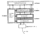
図3に、従来の例としてデジタルカメラ、PC及びプリンタを接続したときの画像処理システムのブロック構成図を示す。
図3において、31はデジタルカメラ、32はパソコン(PC)、33はプリンタである。さらに、デジタルカメラ31において、34はデジタルカメラの記録部であるメモリ、35は画像データの復号化回路、36は画像処理部、37はD/Aコンバータ、38は表示部であるEVF、39はデジタルカメラのデジタルI/O部である。PC32において、40はPCのデジタルカメラとのデジタルI/O部、41はキーボードなどの操作部、42は画像データの復号化回路、43はディスプレイ、44はハードディスク装置、45はRAM等のメモリ、46は演算処理部のMPU、47はPCIバス、48はデジタルI/FのSCSIインターフェース(ボード)である。プリンタ33において、49はPCとSCSIケーブルで繋がったプリンタのSCSIインターフェイス、50はメモリ、51はプリンタヘッド、52はプリンタ制御部のプリンタコントローラ、53はドライバである。
【0006】
デジタルカメラで撮像した画像をPCに取り込み、またPCからプリンタへ出力するときの手順の説明を行う。デジタルカメラ31のメモリ34に記憶されている画像データが読み出されると、読み出された画像データのうち一方は復号化回路35で復号化され、画像処理回路36で表示するための画像処理がなされ、D/Aコンバータ37を経て、EVF38で表示される。また一方では、外部出力するためにデジタルI/O部39から、ケーブルを伝わってPC32のデジタルI/O部40へ至る。
【0007】
PC32内では、PCIバス47を相互伝送のバスとして、デジタルI/O部40から入力した画像データは、記憶する場合はハードディスク44で記憶され、表示する場合は復号化回路42で復号化された後、メモリ45で表示画像としてメモりされて、ディスプレイ43でアナログ信号に変換されてから表示される。PC32での編集時等の操作入力は操作部41から行い、PC32全体の処理はMPU46で行う。
【0008】
また、画像をプリント出力する際は、PC32内のSCSIインターフェイスボード48から画像データをSCSIケーブルにのせて伝送し、プリンタ33側のSCSIインターフェイス49で受信し、メモリ50でプリント画像として形成され、プリンタコントローラ52の制御でプリンタヘッド51とドライバ53が動作して、メモリ50から読み出したプリント画像データをプリントする。
【0009】
以上が、従来の画像データをPCに取り込み、またはプリントするまでの手順である。
このように、従来はホストであるPCにそれぞれの機器が接続され、PCを介してから、記録再生装置で撮像した画像データをプリントしている。
また、映像データを圧縮する方式も多様化している。静止画を圧縮する方式としてJPEG、動画を圧縮する方式としてMPEG、などが知られており、その他には家庭用デジタルVTR(DVC)ではVLCとDCTを組み合わせた独自の圧縮方式を用いている。このように、機器毎またはデータの種類毎などに分類してさまざまな圧縮方式が考えられている。
【0010】
【発明が解決しようとする課題】
しかしながら、上記従来例であげたデジタルインターフェイスの問題点として、SCSI等には、転送データレートの低いものや、パラレル通信のためケーブルが太いもの、接続される周辺機器の種類や数、接続方式などにも制限があり、多くの面での不便さも指摘されている。
【0011】
また、一般的な家庭用PCの多くは、PCの背面にSCSIやその他のケーブルを接続するためのコネクタを設けているものが多く、またコネクタの形状も大きくて、抜き差しに煩わしさがある。デジタルカメラやビデオカメラ等の移動式や携帯式であって、通常は据え置きしない装置を接続するときにも、PCの背面コネクタに接続しなければならず、非常に煩わしい。
【0012】
また、通常パソコンには多くの周辺機器が接続されており、今後は更に周辺装置の種類が増え、さらにはI/Fの改良などによって、PC周辺装置に限らず多くのデジタル機器間をネットワーク接続した通信が可能になると、非常に便利になる反面、機器間によってはデータ量の非常に多い通信も頻繁に行われるようになるので、ネットワークを混雑させてしまい、ネットワーク内での他の機器間における通信に影響をもたらすことも考えられる。例えば、ユーザが画像プリントを続けてまたは迅速に行いたいときなどのPC−プリンタ間のデータ通信に対し、ユーザが意識していない機器間同士の通信によりネットワーク全体、またはホスト役のPC等が影響を受け、画像のプリントが正常に実行されなかったり、遅れたりすることも考えられる。このように、ネットワークの混雑によるPCに対する負荷の増加や、PCの動作状況によるデータ通信等の不具合も存在することとなる。
【0013】
本発明は、前記従来の欠点を除去し、転送先ノードから転送元ノードに該転送先ノードのデータの処理能力の情報を報知することで、転送先ノードのもつ処理能力の差にとらわれず常に高効率なデータ転送を行うデータ転送方法及び画像処理システムと装置を提供する。
【0014】
【課題を解決するための手段】
この課題を解決するために、本発明のデータ転送方法は、転送元ノードから転送先ノードへデータを転送するデータ転送方法であって、転送先ノードが具備しているデータ処理能力に応じて決められるデータ形式のデータの転送に先立って、前記転送先ノードが要求するデータのアドレス情報を、前記転送先ノードから前記転送元ノードに報知し、前記転送先ノードにおけるデータ処理の終了に伴う信号を、前記転送先ノードから前記転送元ノードに対して送信し、前記データ処理の終了に伴う信号に応じて前記転送元ノードから送出された、前記アドレス情報で指定された前記データ形式のデータを、前記転送先ノードが受信することを特徴とする。
【0015】
ここで、前記転送元ノーと転送先ノード間は汎用のデジタルインタフェースで接続されており、前記汎用のデジタルインタフェースはアシンクロナス転送とアイソクロナス転送とが混在する1394シリアルバスであり、前記データはアシンクロナス転送またはアイソクロナス転送を用いて前記転送元ノードより前記転送先ノードに送られる。また、前記転送元ノーと転送先ノード間は汎用のデジタルインタフェースで接続されており、前記汎用のデジタルインタフェースはアシンクロナス転送とアイソクロナス転送とが混在する1394シリアルバスであり、前記アドレス情報はアシンクロナス転送を用いて前記転送先ノードより前記転送元ノードに送られる。
【0016】
又、本発明のシステムは、複数の機器からなり、該複数の機器間で転送元ノードから転送先ノードへデータを転送して処理するシステムであって、転送先ノードが、前記転送先ノードが具備しているデータ処理能力に応じて決められるデータ形式のデータの転送に先立って、前記転送先ノードの要求するデータのアドレス情報を、前記転送元ノードに報知する報知手段と、前記転送先ノードにおけるデータ処理の終了に伴う信号を、前記転送元ノードに対して送信する送信手段と、前記データ処理の終了に伴う信号に応じて前記転送元ノードから送出された、前記アドレス情報で指定された前記データ形式のデータを受信する受信手段とを有することを特徴とする。
【0020】
又、本発明の再生装置は、画像処理装置と通信可能な再生装置であって、前記画像処理装置が具備しているデータ処理能力に応じて決められるデータ形式の画像データの送信に先立って、前記画像処理装置から送信された、前記画像処理装置の要求する画像データのアドレス情報を受信する第1受信手段と、前記画像処理装置における画像データ処理の終了に伴う信号を受信する第2受信手段と、前記画像データ処理の終了に伴う信号の受信に応じて、前記アドレス情報で指定された前記データ形式の画像データを、前記画像処理装置へ送信する送信手段とを有することを特徴とする。
ここで、前記画像処理装置はプリンタであり、前記画像データ処理の終了に伴う信号は、プリント処理の終了に伴う信号である。また、前記画像処理装置とは汎用のデジタルインタフェースで接続されており、前記汎用のデジタルインタフェースはアシンクロナス転送とアイソクロナス転送とが混在する1394シリアルバスであり、前記第1受信手段は、前記アドレス情報をアシンクロナス転送を用いて受信し、前記送信手段は、画像データをアシンクロナス転送またはアイソクロナス転送を用いて送信する。
【0021】
又、本発明の画像処理装置は、再生装置から画像データを受信する画像処理装置であって、前記画像処理装置が具備しているデータ処理能力に応じて決められるデータ形式の画像データの受信に先立って、前記画像処理装置が要求する画像データのアドレス情報を、前記再生装置に報知する報知手段と、前記画像処理装置における画像データ処理の終了に伴う信号を、前記再生装置に対して送信する送信手段と、前記画像データ処理の終了に伴う信号に応じて前記再生装置から送出された、前記アドレス情報で指定された前記データ形式の画像データを受信する受信手段を有することを特徴とする。ここで、前記再生装置とは汎用のデジタルインタフェースで接続されており、前記汎用のデジタルインタフェースはアシンクロナス転送とアイソクロナス転送とが混在する1394シリアルバスであり、前記画像データは、アシンクロナス転送またはアイソクロナス転送を用いて前記再生装置より受信する。また、前記再生装置とは汎用のデジタルインタフェースで接続されており、前記汎用のデジタルインタフェースはアシンクロナス転送とアイソクロナス転送とが混在する1394シリアルバスであり、前記アドレス情報は、アシンクロナス転送を用いて前記再生装置に送信する。また、更に、受信した画像データをプリント処理するプリント手段を有し、前記画像データ処理の終了に伴う信号は、プリント処理の終了に伴う信号である。
又、本発明の画像処理装置の制御方法は、再生装置から画像データを受信する画像処理装置の制御方法であって、前記画像処理装置が具備しているデータ処理能力に応じて決められるデータ形式の画像データの受信に先立って、前記画像処理装置が要求する画像データのアドレス情報を、前記再生装置に報知し、前記画像処理装置における画像データ処理の終了に伴う信号を、前記再生装置に対して送信し、前記画像データ処理の終了に伴う信号に応じて前記再生装置から送出された、前記アドレス情報で指定された前記データ形式の画像データを受信することを特徴とする。ここで、前記画像データ処理の終了に伴う信号は、前記画像処理装置におけるプリント処理の終了に伴う信号である。
【0025】
【発明の実施の形態】
以下、本発明の実施の形態を添付図面に従って詳細に説明する。
<本実施の形態の画像処理システムの概要>
本実施の形態では、従来からあるデジタルI/Fの問題点を極力解消し、各デジタル機器に統一されているような汎用型デジタルI/F、例えばIEEE1394−1995ハイパフォーマンス・シリアルバスを用いて、PCやプリンタ、その他周辺装置、またはデジタルカメラやデジタルVTRの記録再生装置等をネットワーク構成で接続したときの機器間データ通信を実現し、記録再生装置からビデオデータ等のPCへの取り込み、また、映像データをプリンタへ直接転送しプリントする、所謂ダイレクトプリント等を実現する。
【0026】
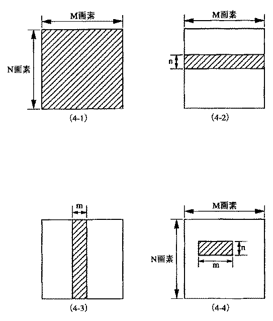
即ち、プリンタから見ればPCに接続される場合や、直接デジタルカメラやデジタルビデオカメラに接続される場合のいずれにも適用できるようになる。更に、例えばプリンタに含まれる前述のメモリ50は、プリンタの方式・種類によってもその容量は一定ではなく、図4に示したように、縦方向の総画素数Nから横方向の総画素数Mで表わされるN×Mドットの画像情報を持つ(4−1)タイプや、縦方向の所定画素数nを横方向全般にわたって持つ(4−2)タイプ、これとは逆に横方向の所定画素数mを縦方向全般にわたって持つ(4−3)タイプ、そして縦方向及び横方向それぞれ所定だけの容量のメモリだけしか持たない(4−4)タイプと、それぞれ特徴を有していることに鑑み、プリンタのメモリ容量に応じた最適なデータ転送のブロックサイズを決定する。
【0027】
また、実装されているプリンタエンジンの印刷能力に応じて画像データのフォーマットを決定することで、任意のブロックサイズに収まるようにデータ転送を行うものである。
本実施の形態によれば、プリンタを接続するデジタルI/FとしてIEEE1394シリアルバスを用い、後で詳細に説明するIEEE1394シリアルバスの特徴である非同期(アシンクロナス)転送モードを用い、プリンタ側で持っている画像データを一括ストアするメモリ容量に対応した、印刷画像の空間的アドレス情報の開始点から終了点までに相当する、画像データの転送開始アドレスから転送終了アドレスを、プリンタ側からPCあるいはデジタルカメラ等に指令信号として送信し、この指令信号を受信したPCあるいはデジタルカメラ等はプリンタ側のメモリに対して一度に転送するのに必要なサイズのデータ容量を決定して画像データを転送するという方式である。
【0028】
また、プリンタ側で実装されたプリンタエンジンの、印刷処理能力を指名した指令信号を用いた場合は、その指令信号に応じて画像データのフォーマット(YUV、4:1:1、4:2:2、4:4:4等)を任意に選択することで、この指令信号を受信したPCあるいはデジタルカメラ等は一度に送る画像データの容量を一定量に収まるようにするという方式である。
【0029】
これによりIEEE1394シリアルバス上でのデータ転送の効率も向上するので、複数の機器が接続されたネットワーク上においても、周辺機器間のデータ転送スループットを悪化させず、プリンタ側のデータ待ち時間も短縮し印刷スループットを向上させることが可能となる。
[実施の形態1]
以下、本発明の実施の形態1について図面を参照しながら説明する。
【0030】
図1と図5に本実施の形態の画像処理システムのネットワーク構成の例を示す。
<IEEE1394の技術の概要>
ここで、本実施の形態では、各機器間を接続するデジタルI/FをIEEE1394シリアルバスを用いるので、IEEE1394シリアルバスについてあらかじめ説明をする。
【0031】
家庭用ディジタルVTRやDVDの登場に伴なって、ビデオデータやオーディオデータなどのリアルタイムでかつ高情報量のデータ転送サポートが必要になっている。こういったビデオデータやオーディオをリアルタイムで転送し、パソコン(PC)に取り込んだり、またはその他のデジタル機器に転送を行うには、必要な転送機能を備えた高速データ転送可能なインタフェースが必要になってくるものであり、そういった観点から開発されたインタフェースがIEEE1394−1995(High Performance Serial Bus) (以下1394シリアルバス)である。
【0032】
図7に1394シリアルバスを用いて構成されるネットワーク・システムの例を示す。このシステムは機器A,B,C,D,E,F,G,Hを備えており、A−B間、A−C間、B−D間、D−E間、C−F間、C−G間、及びC−H間をそれぞれ1394シリアルバス用のツイスト・ペア・ケーブルで接続されている。これら機器A〜Hは例としてPC、デジタルVTR、DVD、デジタルカメラ、ハードディスク、モニタ等である。
【0033】
各機器間の接続方式は、ディジーチェーン方式とノード分岐方式とを混在可能としたものであり、自由度の高い接続が可能である。
また、各機器は各自固有のIDを有し、それぞれが認識し合うことによって1394シリアルバスで接続された範囲において、1つのネットワークを構成している。各デジタル機器間をそれぞれ1本の1394シリアルバスケーブルで順次接続するだけで、それぞれの機器が中継の役割を行い、全体として1つのネットワークを構成するものである。また、1394シリアルバスの特徴であるPlug&Play機能で、ケーブルを機器に接続した時点で自動で機器の認識や接続状況などを認識する機能を有している。
【0034】
また、図7に示したようなシステムにおいて、ネットワークからある機器が削除されたり、または新たに追加されたときなど、自動的にバスリセットを行い、それまでのネットワーク構成をリセットしてから、新たなネットワークの再構築を行う。この機能によって、その時々のネットワークの構成を常時設定、認識することができる。
【0035】
また、データ転送速度は、100/200/400Mbpsと備えており、上位の転送速度を持つ機器が下位の転送速度をサポートし、互換性をとるようになっている。データ転送モードとしては、コントロール信号などの非同期データ(Asynchronousデータ:以下、Asyncデータ)を転送するAsynchronous転送モード、リアルタイムなビデオデータやオーディオデータ等の同期データ(Isochronous データ:以下、Isoデータ)を転送するIsochronous転送モードがある。このAsyncデータとIsoデータは各サイクル(125μsS)の中において、サイクル開始を示すサイクル・スタート・パケット(CSP)の転送に続き、IsOデータの転送を優先しつつサイクル内で混在して転送される。
【0036】
次に、図8に1394シリアルバスの構成要素を示す。
1394シリアルバスは全体としてレイヤ(階層)構造で構成されている。図8に示したように、最もハード的なのが1394シリアルバスのケーブルであり、そのケーブルのコネクタが接続されるコネクタポートがあり、その上にハードウェアとしてフィジカル・レイヤとリンク・レイヤがある。
【0037】
ハードウェア部は、実質的なインターフェースチップの部分であり、そのうちフィジカル・レイヤは符号化やコネクタ関連の制御等を行い、リンク・レイヤはパケット転送やサイクルタイムの制御等を行う。ファームウェア部のトランザクション・レイヤは、転送(トランザクション)すべきデータの管理を行い、ReadやWriteといった命令を出す。シリアスバスマネージメントは、接続されている各機器の接続状況やIDの管理を行い、ネットワークの構成を管理する部分である。このハードウェアとファームウェアまでが実質上の1394シリアルバスの構成である。
【0038】
またソフトウェア部のアプリケーション・レイヤは使うソフトによって異なり、インターフェース上にどのようにデータをのせるか規定する部分であり、AVプロトコルなどのプロトコルによって規定されている。
以上が1394シリアルバスの構成である。
次に、図9に1394シリアルバスにおけるアドレス空間の図を示す。
【0039】
1394シリアルバスに接続された各機器(ノード)には必ず各ノード固有の64ビットアドレスを持たせておく。そしてこのアドレスをROMに格納しておくことで、自分や相手のノードアドレスを常時認識でき、相手を指定した通信も行える。
1394シリアルバスのアドレッシングは、IEEE1212に準じた方式であり、アドレス設定は、最初の10bitがバスの指定用に、次の6bitがノードID番号の指定用に使われる。残りの48bitが機器に与えられたアドレス幅になり、それぞれ固有のアドレス空間として使用できる。最後の28bitは固有データの領域として、各機器の識別や使用条件の設定の情報などを格納する。
【0040】
以上がシリアルバスの技術の概要である。
(バスリセットのシーケンス)
1394シリアルバスでは、接続されている各機器(ノード)にはノードIDが与えられ、ネットワーク構成として認識されている。
このネットワーク構成に変化があったとき、例えばノードの挿抜や電源のON/OFFなどによるノード数の増減などによって変化が生じて、新たなネットワーク構成を認識する必要があるとき、変化を検知した各ノードはバスにバスリセット信号を送信して、新たなネットワーク構成を認識するモードに入る。このときの変化の検知方法は、1394ポート基盤上でのバイアス電圧の変化を検知することに因って行われる。
【0041】
あるノードからバスリセット信号が伝達されて、各ノードのフィジカルレイヤはこのバスリセット信号を受けると同時にリンクレイヤにバスリセットの発生を伝達し、かつ他のノードにバスリセット信号を伝送する。最終的にすべてのノードがバスリセット信号を受信した後、バスリセットが起動となる。バスリセットは、先に述べたようなケーブル抜挿や、ネットワーク異常等によるハード検出による起動と、プロトコルからのホスト制御などによってフィジカルレイヤに直接命令を出すことによっても起動する。
【0042】
また、バスリセットが起動するとデータ転送は一時中断され、この間のデータ転送は待たされ、終了後、新しいネットワーク構成のもとで再開される。
以上がバスリセットのシーケンスである。
(ノードID決定のシーケンス)
バスリセットの後、各ノードは、新しいネットワーク構成を構築するために、各ノードにIDを与える動作に入る。このときの、バスリセットからノードID決定までの一般的なシーケンスを、図17のフローチャートを用いて説明する。
【0043】
図17のフローチャートは、バスリセットの発生からノードIDが決定し、データ転送が行えるようになるまでの一連のバスの作業を示してある。
先ず、ステップS101として、ネットワーク内にバスリセットが発生することを常時監視していて、ここでノードの電源ON/OFFなどでバスリセットが発生するとステップS102に移る。
【0044】
ステップS102では、ネットワークがリセットされた状態から、新たなネットワークの接続状況を知るために、直接接続されている各ノード間において親子関係の宣言がなされる。ステップS103として、すべてのノード間で親子関係が決定すると、ステップS104として一つのルートが決定する。すべてのノード間で親子関係が決定するまで、ステップS102の親子関係の宣言を行い、またルートも決定されない。
【0045】
ステップS104でルートが決定されると、次はステップS105として、各ノードにIDを与えるノードIDの設定作業が行われる。所定のノード順序で、ノードIDの設定が行われ、すべてのノードにノードIDが与えられるまで繰り返し設定作業が行なわれ、最終的にステップS106としてすべてのノードにIDを設定し終えたら、新しいネットワーク構成がすべてのノードにおいて認識されたので、ステップS107としてノード間のデータ転送が行える状態となり、データ転送が開始される。
【0046】
このステップS107の状態になると、再びバスリセットが発生するのを監視するモードに入り、バスリセットが発生したらステップS101からステップS106までの設定作業が繰り返し行われる。
(Asynchronous(非同期)転送)
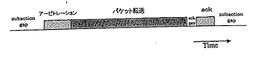
アシンクロナス転送は、非同期転送である。図12にアシンクロナス転送における時間的な遷移状態を示す。図12の最初のサブアクション・ギャップは、バスのアイドル状態を示すものである。このアイドル時間が一定値になった時点で、転送を希望するノードはバスが使用できると判断して、バス獲得のためのアービトレーションを実行する。
【0047】
アービトレーションでバスの使用許可を得ると、次にデータの転送がパケット形式で実行される。データ転送後、受信したノードは転送されたデータに対しての受信結果のack(受信確認用返送コード)をackgapという短いギャップの後、返送して応答するか、応答パケットを送ることによって転送が完了する。acKは4ビットの情報と、4ビットのチェックサムからなり、成功か、ビジー状態か、ペンディング状態であるかといった情報を含み、すぐに送信元ノードに返送される。
【0048】
次に、図13にアシンクロナス転送のパケットフォーマットの例を示す。
パケットには、データ部及び誤り訂正用のデータCRCの他にはヘッダ部が有り、そのヘッダ部には図13に示したような、目的ノードID、ソースノードID、転送データ長さや各種コードなどが書き込まれ、転送が行われる。
また、アシンクロナス転送は自己ノードから相手ノードへの1対1の通信である。転送元ノードから転送されたパケットは、ネットワーク中の各ノードに行き渡るが、自分宛てのアドレス以外のものは無視されるので、宛先の1つのノードのみが読込むことになる。
【0049】
以上がアシンクロナス転送の説明である。
(Isochronous (同期)転送)
アイソクロナス転送は同期転送である。1394シリアルバスの最大の特徴であるともいえるこのアイソクロナス転送は、特にVIDEO映像データや音声データといったマルチメディアデータなど、リアルタイムな転送を必要とするデータの転送に適した転送モードである。
【0050】
また、アシンクロナス転送(非同期)が1対1の転送であったのに対し、このアイソクロナス転送はブロードキャスト機能によって、転送元の1つのノードから他のすべてのノードへ一様に転送される。
図14はアイソクロナス転送における、時間的な遷移状態を示す図である。
アイソクロナス転送は、バス上一定時間毎に実行される。この時間間隔をアイソクロナスサイクルと呼ぶ。アイソクロナスサイクル時間は、125μSである。この各サイクルの開始時間を示し、各ノードの時間調整を行う役割を担っているのがサイクル・スタート・パケットである。サイクル・スタート・パケットを送信するのは、サイクル・マスタと呼ばれるノードであり、1つ前のサイクル内の転送終了後、所定のアイドル期間(サブアクションギャップ)を経た後、本サイクルの開始を告げるサイクル・スタート・パケットを送信する。このサイクル・スタート・パケットの送信される時間間隔が125μSとなる。
【0051】
また、図14にチャネルA、チャネルB、チャネルCと示したように、1サイクル内において複数種のパケットがチャネルIDをそれぞれ与えられることによって、区別して転送できる。これによって同時に複数ノード間でのリアルタイムな転送が可能であり、また受信するノードでは自分が欲しいチャネルIDのデータのみを取り込む。このチャネルIDは送信先のアドレスを表すものではなく、データに対する論理的な番号を与えているに過ぎない。よって、あるパケットの送信は1つの送信元ノードから他のすべてのノードに行き渡る、ブロードキャストで転送されることになる。
【0052】
アイソクロナス転送のパケット送信に先立って、アシンクロナス転送同様アービトレーションが行われる。しかし、アシンクロナス転送のように1対1の通信ではないので、アイソクロナス転送にはack(受信確認用返信コード)は存在しない。
また、図14に示したisogap(アイソクロナスギャップ)とは、アイソクロナス転送を行う前にバスが空き状態であると認識するために必要なアイドル期間を表している。この所定のアイドル期間を経過すると、アイソクロナス転送を行いたいノードはバスが空いていると判断し、転送前のアービトレーションを行うことができる。
【0053】
次に、図15にアイソクロナス転送のパケットフォーマットの例を示し、説明する。
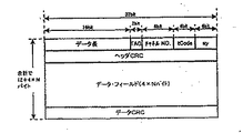
各チャネルに分かれた、各種のパケットにはそれぞれデータ部及び誤り訂正用のデータCRCの他にヘッダ部があり、そのヘッダ部には図15に示したような、転送データ長やチャネルNo、その他各種コード及び誤り訂正用のヘッダCRCなどが書き込まれ、転送が行われる。
【0054】
以上がアイソクロナス転送の説明である。
(バス・サイクル)
実際の1394シリアルバス上の転送では、アイソクロナス転送と、アシンクロナス転送は混在できる。その時の、アイソクロナス転送とアシンクロナス転送が混在した、バス上の転送状態の時間的な遷移の様子を表した図を図16に示す。
【0055】
アイソクロナス転送はアシンクロナス転送より優先して実行される。その理由は、サイクル・スタート・パケットの後、アシンクロナス転送を起動するために必要なアイドル期間のギャップ長(サブアクションギャップ)よりも短いギャップ長(アイソクロナスギャップ)で、アイソクロナス転送を起動できるからである。したがって、アシンクロナス転送より、アイソクロナス転送は優先して実行されることになる。
【0056】
図16に示した、一般的なバスサイクルにおいて、サイクル#mのスタート時にサイクル・スタート・パケットがサイクル・マスタから各ノードに転送される。これによって、各ノードで時刻調整を行い、所定のアイドル期間(アイソクロナスギャップ)を待ってからアイソクロナス転送を行なうべきノードはアービトレーションを行い、パケット転送に入る。図16ではチャネルeとチャネルsとチャネルkが順にアイソクロナス転送されている。
【0057】
このアービトレーションからパケット転送までの動作を、与えられているチャネル分繰り返し行った後、サイクル#mにおけるアイソクロナス転送がすべて終了したら、アシンクロナス転送を行うことができるようになる。
アイドル時間がアシンクロナス転送が可能なサブアクションギャップに達することによって、アシンクロナス転送を行いたいノードはアービトレーションの実行に移れると判断する。
【0058】
ただし、アシンクロナス転送が行える期間は、アイソクロナス転送終了の後、次のサイクル・スタート・パケットを転送すべき時間(cycle synch) までの間にアシンクロナス転送を起動するためのサブアクションギャップが得られた場合に限っている。
図16のサイクル#mでは3つのチャネル分のアイソクロナス転送と、その後アシンクロナス転送(含むack)が2パケット(パケット1,パケット2)転送されている。このアシンクロナスパケット2の後は、サイクルm+1をスタートすべき時間(cycle synch) にいたるので、サイクル#mでの転送はここまでで終わる。
【0059】
ただし、非同期または同期転送動作中に次のサイクル・スタート・パケットを送信すべき時間(cycle synch) に至ったとしたら、無理に中断せず、その転送が終了した後のアイドル期間を待ってから次サイクルのサイクル・スタート・パケットを送信する。即ち、1つのサイクルが125μS以上続いたときは、その分次サイクルは基準の125μSより短縮されたとする。このようにアイソクロナス・サイクルは125μSを基準に超過、短縮し得るものである。
【0060】
しかし、アイソクロナス転送はリアルタイム転送を維持するために毎サイクル必要であれば必ず実行され、アシンクロナス転送はサイクル時間が短縮されたことによって次以降のサイクルにまわされることもある。
こういった遅延情報も含めてサイクル・マスタによって管理される。
以上が,IEEE1394シリアルバスの概略説明である。
【0061】
<実施の形態1の画像処理システムの構成例>
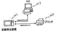
図1のように1394シリアルバスケーブルで各機器が接続されたときの説明を行う。図1でのバス構成は、実線で描いた1394シリアルバスで接続された、101記録再生装置、102プリンタ装置、103パソコン(PC)で成り立っており、各機器がそれぞれ1394シリアルバスの仕様に基づいたデータ転送が行える。ここで、101記録再生装置とは動画または静止画を記録再生するデジタルカメラやカメラ一体型デジタルVTR等である。また、記録再生装置101で出力する映像データを、プリンタ102に直接転送すればダイレクトプリントが可能である。また、1394シリアルバスの接続方法は、図1のような接続に限ったものではなく、任意の機器間での接続バスを構成しても可能であり、また図1に示した機器のほかにもデータ通信機器が接続された構成であってもよい。なお、この図1のネットワークは一例とした機器群であって、接続されている機器は、ハードディスクなどの外部記憶装置や、CDR,DVD等の1394シリアルバスでネットワークが構成できる機器なら何でもよい。
【0062】
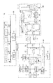
図1のようなバス構成を背景として、本発明の実施例の動作に関する説明を、図2を用いて行う。図2の101は記録再生装置、102はプリンタ、103はPCである。
記録再生装置101において、4は撮像系、5はA/Dコンバータ、65は映像信号処理回路、7は所定のアルゴリズムで記録時に圧縮、再生時に伸張を行う圧縮/伸張回路、8は磁気テープや固体メモリ等とその記録再生ヘッド等も含めた記録再生系、9はシステムコントローラ、10は指示入力を行う操作部、11はD/Aコンバータ、12は表示部であるEVF、13は非圧縮で転送する映像データを記憶するフレームメモリ、14はメモリ13の読み出し等を制御するメモリ制御部、17はデータセレクタ、18は1394シリアルバスのI/F部である。
【0063】
プリンタ102において、19はプリンタにおける1394I/F部、20はデータセレクタ、22はプリント画像の画像処理回路、23はプリント画像を形成する為のメモリ、24はプリンタヘッド、25はプリンタヘッドや紙送り等を行うドライバ、26はプリンタの制御部であるプリンタコントローラ、27はプリンタ操作部である。
【0064】
PC103において、61はPCに搭載された1394I/F部、62はPCIバス、63はMPU、65はD/Aコンバータも内蔵しているディスプレイ、66はHDD、67はメモリ、68はキーボードやマウスといった操作部である。
尚、破線で示したように、記録再生装置101が圧縮された画像データをそのまま送出する構成であるメモリ15及びメモリ制御部16を有し、プリンタ102が所定のアルゴリズムで圧縮された映像データを複号化するための複号化回路21を有し、PC103が所定のアルゴリズムで圧縮された映像データを複号化するための複号化回路64を有するように構成してもよい。
【0065】
<実施の形態1の画像処理システムの動作例>
次に、このブロック図2の動作を順を追って説明する。以下の説明では複雑さをなくすために、上記圧縮された画像データをそのまま送出する構成についての説明は省く。又、記録再生装置101、プリンタ102、PC103の制御は、それぞれが有する外部記憶装置の記憶媒体からRAM内にロードされた制御プログラムを実行することにより実現してもよいし、記録再生装置101、プリンタ102の制御プログラムの少なくとも一部はPC103からダウンロードされる構成であってもよい。
【0066】
まず、記録再生装置101の記録時、撮像系4で撮影した映像信号は、A/Dコンバータ5でデジタル化された後、映像信号処理回路6で映像処理がなされる。映像信号処理回路6の出力の一方は撮影中の映像としてD/Aコンバータ11でアナログ信号に戻され、EVF12で表示される。その他の出力は、圧縮回路7で所定のアルゴリズムで圧縮処理され、記録再生系8で記録媒体に記録される。ここで、所定の圧縮処理とは、デジタルカメラでは代表的なものとしてJPEG方式、家庭用デジタルVTRでは帯域圧縮方法としてのDCT(離散コサイン変換)及びVLC(可変長符号化)に基づいた圧縮方式、その他としてMPEG方式などである。
【0067】
再生時は、記録再生系8が記録媒体から所望の映像を再生する。この時、所望の映像の選択は、操作部10から入力された指示入力を元にして選択され、システムコントローラ9が制御して再生する。記録媒体から再生された映像データのうち、圧縮状態のまま転送されるデータはフレームメモリ15に出力する。非圧縮のデータで転送するため再生データを伸張するときは、伸張回路7で伸張されメモリ13に出力される。また、再生した映像データをEVF12で表示するときは、伸張回路7で伸張し、D/Aコンバータ11でアナログ信号に戻された後EVF12に出力され、表示される。
【0068】
フレームメモリ13は、システムコントローラにて制御されたメモリ制御部14で書き込み/読み出しの制御がなされて、読み出された映像データはデータセレクタ17へと出力される。
システムコントローラ9は記録再生装置101内の各部の動作を制御するものであるが、プリンタ102やPC103といった外部に接続された機器に対する制御コマンドデータを出力して、データセレクタ17から1394シリアルバスを転送されて外部の装置にコマンド送信することも出来る。また、プリンタ102やPC103から転送されてきた各種コマンドデータは、データセレクタ17からシステムコントローラ9に入力され、記録再生装置101の各部の制御に用いることができる。このうち、プリンタ102、PC103から転送されたデコーダの有無、またはデコーダの種類等を示すコマンドデータは、要求コマンドとしてシステムコントローラ9に入力した後、記録再生装置101より映像データを転送する際、メモリ制御部14にコマンド伝達して、フレームメモリ13の映像データを読み出して転送するように制御する。メモリ13のコマンド制御はプリンタ102からの後述するデータリクエスト情報に基づいて制御される。
【0069】
データセレクタ17に入力した映像データ及びコマンドデータは、1394I/F18で1394シリアルバスの仕様に基づいてケーブル上をデータ転送され、プリント用映像データならばプリンタ102が、PCに取り込む映像データならばPC103が受信する。コマンドデータも適宜対象ノードに対して転送される。各データの転送方式については、主に動画や静止画、または音声といったデータはIsoデータとしてアイソクロナス転送方式で転送し、コマンドデータはAsync データとしてアシンクロナス転送方式で転送する。ただし、通常Isoデータで転送するデータのうち、転送状況等に応じて場合によってはAsync データとして転送した方が都合がいいときはアシンクロナス転送で送ってもよい。
【0070】
次にプリンタ102の動作については、1394I/F部19に入力したデータの内、データセレクタ20で各データの種類毎に分類され、映像データ等プリントすべきデータは、画像処理回路22に出力される。
画像処理回路22に入力されたプリント用のデータは、ここでプリントに適した画像処理が施され、かつプリンタコントローラ26によって記憶、読み出しの制御がなされたメモリ23にプリント画像として形成したものをプリンタヘッド24に送りプリントされる。プリンタのヘッド駆動や紙送り等の駆動はドライバ25で行うものであり、ドライバ25やプリンタヘッド24の動作制御、およびその他各部の制御はプリントコントローラ23によって行われる。
【0071】
プリンタ操作部27は紙送りや、リセット、インクチェック、プリンタ動作のスタンバイ/開始/停止等の動作を指示入力するためのものであり、その指示入力に応じてプリンタコントローラ26によって各部の制御がされる。1394I/F部19に入力したデータが、プリンタ102に対するコマンドデータであったときは、データセレクタ20からプリンタコントローラ26に制御コマンドとして伝達され、プリンタコントローラ26によって情報に対応したプリンタ102各部の制御がなされる。また、プリンタコントローラ26は、記録再生装置101及びPC103にコマンドデータを転送することができる。
【0072】
このように、記録再生装置101からプリンタ102に映像データが転送されプリントするときは、所謂ダイレクトプリントであり、PCでの処理を用いずにプリント処理が可能である。
次に、PC103での処理について説明する。
記録再生装置101から、PCの1394I/F部61に転送された映像データは、PC103内で、PCIバス62をデータ相互伝送のバスとして用いて、各部へ転送される。また、PC103内の各種コマンドデータ等もこのPCIバスを用いて各部へ転送される。
【0073】
PC103では操作部68からの指示入力と、OS(オペレーティングシステム)やアプリケーションソフトにしたがって、メモリ67を用いながら、MPU63によって処理がなされる。転送された映像データを記録するときはハードディスク66で記録する。
転送される映像データは、プリンタと同様本実施の形態では非圧縮データであるが、もしPC103側に圧縮データを伸長するデコーダ機能(複号化回路64)を有していれば、圧縮データを送出してもよい。映像データをディスプレイ65で表示するときは、圧縮された映像データであったときは複号化回路64で複号化された後、非圧縮の映像データであったときは直接ディスプレイ65に入力され、D/A変換された後、映像表示される。
【0074】
PC103に設けられた各種複号化回路64とは、一例としてMPEG方式等のデコーダをボードとしてスロットに差し込んだものや、もしくはハード的に本体に組み込まれたもの、または、MPEG方式やNPEJ方式、その他のソフトデコーダをROM等によって所有しているものであり、これらデコーダの種類や有無を情報としてコマンドを記録再生装置101に転送することができる。
【0075】
このようにして、転送された映像データはPC103内に取り込まれ、記録、編集、PCから他機器に転送等がなされる。
以上がブロック図2についての説明である。
<実施の形態1の動作フローチャート例>
次に、この時の動作をフローチャートにして図6に示す。図6では、図2における記録再生装置101内の画像データストア用のメモリ13、及びプリンタ102内の画像データストア用のメモリ23の読み出し/書き込みのアドレスコントロール、及びこれにより転送されるそれぞれのデータの装置間の関連ステップを、フローチャートにして示したものである。
【0076】
まず、プリンタ102側においては、ステップS1に示すように、プリンタ102が固有に有しているメモリ23の容量に対応した、プリンタ印字の最小ユニット単位(略、プリンタサイクルレングス)を設定する手段を有している。これは、前述の図4に示したメモリ容量を記憶しておく画像データの空間的特徴により設定される、印字サイクルに対応したミニマムのデータ量を示す値をセットするステップである。
【0077】
あるタイミングでのサイクルを仮にサイクルCi と呼ぶ。前回のサイクルであるCi-1 での最後に印字したエンドポイントアドレスの情報を決めるステップS2と、かかるステップS1とに基づき、今回のサイクルCi における印字するスタートポイントアドレス(SPA at Ci )とエンドポイントアドレス(EPA at Ci )が設定される(ステップS3)。かかるSPAからEPAまでの順次のアドレス情報は、前述のメモリ23の読み出し用としてステップS4に、更には、読み出されたメモリ23からのデータを用いた、いわゆるプリンタ自体の特有の動作のステップS5に移る。やがてサイクルCi での一連のプリンタ動作が終了すると、終了確認ステップS6により確認作業に入る。
【0078】
一方、前述のステップS3と並行して、次のサイクルであるCi+1 におけるスタートポイントアドレス(SPA at Ci+1)及びエンドポイントアドレス(EPA at Ci+1)を算出するステップS7も起動させ、次回のプリントサイクルに必要となる画像データのアドレスを、送出側である記録再生装置101に前述のIEEE1394のAsyncronus転送により、データ転送する。
【0079】
かかるアドレスデータSPA及びEPAのデータは、前に説明した図12,図13に示すパケット転送によりデータフィールド(4×Nバイト)のうち所定の位置を選んで転送される。装置101内のステップS8では、かかるIEEE1394データで転送されたアドレスデータに対応したデータを記録再生装置101内の画像メモリ13のメモリ書き込み/読み出し用アドレスに変換するステップで、これによりメモリ13の読み出しアドレス設定の為のステップS9に移動する。
【0080】
なお、前述のステップS6でのサイクルCiでの印字終了をうけ、このサイクル印字終了を示すデータは、同様にIEEE1394のAsync転送により前述のアドレスと同様にプリンタ102より記録再生装置101へと転送され、メモリ13からのプリンタ102への画像データそのものの転送が許容される(ステップS10)。
【0081】
記録再生装置101からプリンタ102への画像データ自体のデータ転送は、前述のコマンドデータと同様にAsync転送により図12,13の如く転送してもよいが、図14,15に示すIsochronous 転送により、データフィールドに格納して転送することも可能である。
以上述べた如く、プリンタ102側からは、次回プリンタ印字に必要とされる所定のサイクル分の画像データの位置を示すアドレスデータを、その入力装置である記録再生装置101にAsyncでリクエストとして転送し、そのアドレスに相当するデータを、次にやはりプリンタから送られる現プリントサイクルの終了を示すデータで送出することで、記録再生装置101から画像データをプリンタ102に具備するメモリ23の容量を超えないで最も有効に転送するシステムとなるわけである。
【0082】
なお、図6の説明では、次回印字するアドレスデータをスタートポイントを示す(SPA)データとエンドポイントを示すデータ(EPA)との2つのアドレスデータを送出するという説明を行ったが、スタートポイントを示すデータ(SPA)とその長さを示すデータ(PCL)を送付しても、かまわない。
<実施の形態1の転送データ構成例>
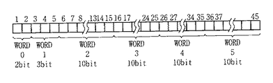
図10に、具体的なアドレス指定等のデータ構成の一例を示す。
【0083】
図10では、全45bit中、データ転送のリクエストを示す2bitのWORD0、メモリタイプを表わす3bitのWORD1、そしてかかるメモリに画像データを転送させる画像の空間的アドレスである座標(x,y)で表わすスタートポイント及びエンドポイントを示す位置データが全部で40bit(WORD2〜WORD5)の例を示している。WORD2の10bit及びWORD3の10bitは、スタートポイントアドレス(SPA)の(Xs,Ys)を示し、WORD4及びWORD5で同様にエンドポイントアドレス(EPA)の(Xe,Ye)を示している(図11を参照)。
【0084】
以下の表1は、データトランスファーリクエストの状態を示すWORD0の割り当てを示す。(0,0)(1,1)はリクエストの有無であるが、(1,0)はやがて近いうちにデータ転送のリクエストが有る状態を示しており、ここでは詳細は説明はしないが、プリント印字終了近傍あるいは画像メモリの読み出し状態等により、その事を判別する。
【0085】
【表1】
【0086】
【表2】
【0087】
【表3】
【0088】
[実施の形態2]
実施の形態2として、プリンタからのリクエストデータとしてプリンタエンジンのパフォーマンスを使った場合について説明する。プリンタエンジンのパフォーマンスとは、図2で示したブロックにおけるプリンタ102の中のプリンタヘッド24とドライバ25によって決定されるプリンタの印刷能力を示すものである。
【0089】
例えば、インクジェットプリンタの場合で説明すると、インクヘッドの吐出ノズルの間隔によって決定されるのが印刷解像度であり、一般的に1インチ当たりのノズル数としてdpi(dot/inch)で示されている。このdpiの数値が高いほど解像度が高くなるので印刷のクオリティが向上する訳だが、実際は画像データの量が解像度に比例して大きくなってしまい、インターフェースにおけるデータ転送速度とプリンタ側の画像データ変換及び印刷速度のバランスが合わなくなると、どちらかに無駄な待ち時間が生じてしまう。
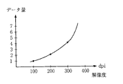
【0090】
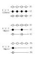
図18は印刷解像度と画像データの量の関係を示した図で、100dpiの時を1とすると、200dpiで4倍、400dpiで16倍、800dpiで64倍の画像データが必要となり、即ち圧縮されていない画像データでは解像度の二乗に比例してデータ量が増えていることがわかる。図19は、YUVで表した画像データの4:4:4、4:2:2、4:1:1の各フォーマットにおける4ピクセルでのデータサイズを示した図で、輝度データYが8ビットで色差データUとVも各8ビットのデータであれば、4:4:4の4ピクセルで12バイト、4:2:2の4ピクセルで8バイト、4:1:1の4ピクセルだと6バイトのデータ量となる。即ちデータフォーマットを切り替えることで、画像データの総量を2/3や1/2に減らすことが可能となる。
【0091】
即ち、プリンタエンジンの解像度が高いプリンタでは画像データのデータフォーマットをデータ量を減らすモードに切り替え、プリンタエンジンの解像度が低いプリンタでは逆に画像データのデータフォーマットはデータ量が多いモードのままにすることで、全体の画像データのデータ量を一定化することができ、一度に転送するデータパケットサイズに対して制限を加えることが可能となる。
【0092】
ここで、データパケットのサイズを一定化することによるメリットについて述べる。
図16に示したように1394シリアルバス上でのデータ転送はアシンクロナス転送とアイソクロナス転送が混在している。アイソクロナス転送はデータ帯域を予約することが可能であるが、対してアシンクロナス転送はシリアルバス上のトラフィックによって転送が待たされることが多くなる。ここで多量のアシンクロナス転送を一度に行おうとしても、確実にデータ転送が実行されるためには他のデータ転送がバスを占有していないことが条件となるし、逆にプリンタがバスを占有してしまうと他のアシンクロナス転送の機器がデータ転送を行えなくなってしまう。すなわち、1対1でつながったシステムであれば気にすることはないが、同じバス上に複数の機器が接続され各々がデータのやり取りをしている場合には大いに問題がある。そこでプリンタエンジンの解像度の情報をデータ転送を行う前にやり取りすることで、解像度に応じてデータフォーマットを切り替えて転送元ノードが画像データを作成し決められたサイズになるようデータパケット化し、転送先ノードはより確実に画像データを受取って印刷動作を行うことが可能となる。
【0093】
また、プリンタエンジンの情報として印刷スピードというパラメータを使うことも同様に可能である。即ちプリンタの単位時間あたりのデータ処理時間がパラメータとなるので、それは解像度であっても印刷スピードであっても同じ内容である。さらに、データパケットのサイズを一定化するのであれば、逆に解像度が上がった時には印刷スピードを遅らせることや、印刷スピードが上がった時は解像度を下げるという設定も可能である。
【0094】
<実施の形態2の転送データ構成例>
図20は具体的なリクエストデータのビット構成を示した図である、まずはじめに、データ転送のリクエストを示す2ビットのWORD0、次に画像フォーマットタイプを表す8ビットのWORD6、プリンタエンジンの解像度を表す32ビットのWORD7、そしてプリンタエンジンのスピードを表す32ビットのWORD8で構成されている。
【0095】
WORD0は、実施の形態1の場合と同じくデータトランスファーリクエストの状態を示すビットである。
WORD6は、プリンタで対応している画像データのフォーマットとして、YUVでの各モードやRGBやモノクロのモードのうち対応しているものを示すビットで、表4のように対応する画像モードのビットに対して”1”を立てるようになっている。即ち複数のモードの対応している場合は、いくつかのビットが立った状態になる。
【0096】
以下の表4に、WORD6の例を示す。
【0097】
【表4】
【0098】
なお、本発明は、複数の機器(例えばホストコンピュータ,インタフェイス機器,リーダ,プリンタなど)から構成されるシステムに適用しても、一つの機器からなる装置(例えば、複写機,ファクシミリ装置など)に適用してもよい。
また、本発明の目的は、前述した実施形態の機能を実現するソフトウェアのプログラムコードを記録した記憶媒体を、システムあるいは装置に供給し、そのシステムあるいは装置のコンピュータ(またはCPUやMPU)が記憶媒体に格納されたプログラムコードを読出し実行することによっても、達成されることは言うまでもない。
【0099】
この場合、記憶媒体から読出されたプログラムコード自体が前述した実施形態の機能を実現することになり、そのプログラムコードを記憶した記憶媒体は本発明を構成することになる。
プログラムコードを供給するための記憶媒体としては、例えば、フロッピディスク,ハードディスク,光ディスク,光磁気ディスク,CD−ROM,CD−R,磁気テープ,不揮発性のメモリカード,ROMなどを用いることができる。
【0100】
また、コンピュータが読出したプログラムコードを実行することにより、前述した実施形態の機能が実現されるだけでなく、そのプログラムコードの指示に基づき、コンピュータ上で稼働しているOS(オペレーティングシステム)などが実際の処理の一部または全部を行い、その処理によって前述した実施形態の機能が実現される場合も含まれることは言うまでもない。
【0101】
さらに、記憶媒体から読出されたプログラムコードが、コンピュータに挿入された機能拡張ボードやコンピュータに接続された機能拡張ユニットに備わるメモリに書込まれた後、そのプログラムコードの指示に基づき、その機能拡張ボードや機能拡張ユニットに備わるCPUなどが実際の処理の一部または全部を行い、その処理によって前述した実施形態の機能が実現される場合も含まれることは言うまでもない。
【0102】
本発明を上記記憶媒体に適用する場合、その記憶媒体には、先に説明した処理手順に対応するプログラムコードを格納することになる。
更に、本明細書では、記録再生装置とプリンタとPCとからなる画像処理システムを例に本発明の説明をしたが、本発明は異なるデータの処理能力を有する機器を汎用インタフェースで接続したシステムでのデータ転送の効率を高める方法を開示するものであって、画像処理システムに限定されず他のデータ処理システムにおいても同様な効果を奏することができる。
【0103】
実施の形態1によれば、転送元ノードから転送先ノードに所定の画像データを送出する際に、転送先ノードが所有している画像データ記録メモリの容量の分だけ順次データ転送を行わせ、その手段として転送先ノードが次に必要とする画像データの空間的アドレスに対応するデータを希望どおりに不具合なく順次データ転送させるシステムを提供することで、転送先ノードのもつ記憶メモリの容量、方式の差にとらわれず常に高効率な転送システムを提供することができる。
実施の形態2によれば、転送先ノードの画像データ処理能力に応じて画像データの解像度やフォーマット等を選択し、一度に転送できるデータパケットサイズを任意に設定することで、複数の機器が接続したシリアルバス上でのデータ転送効率を改善することができる。
【発明の効果】
以上説明したように、本発明によれば、転送先ノードから転送元ノードに、該転送先ノードのデータの処理能力に応じて決められるデータ形式のデータの転送に先立って、前記転送先ノードが要求するデータのアドレス情報を報知し、前記転送先ノードにおけるデータ処理の終了に伴う信号に応じて前記転送元ノードから送出された、前記アドレス情報で指定された前記データ形式のデータを、前記転送先ノードが受信することで、転送先ノードのもつ処理能力の差にとらわれず常に高効率なデータ転送を行うデータ転送方法及び画像処理システムと装置を提供することができる。
【図面の簡単な説明】
【図1】本発明の実施の形態1のネットワーク一例を示した図である。
【図2】実施の形態1を適用した記録再生装置、プリンタ装置、PCのブロック図である。
【図3】従来例で、デジタルカメラ、PC、プリンタをPCを中心に接続した時の構成を示すブロック図である。
【図4】プリンタメモリの領域を示した図である。
【図5】本発明の実施の形態2のネットワーク一例を示した図である。
【図6】実施の形態1でのメモリアドレス設定動作を示すフローチャートである。
【図7】1394シリアルバスを用いて接続されたネットワーク構成の一例を示す図である。
【図8】1394シリアルバスの構成要素を表す図である。
【図9】1394シリアルバスのアドレスマップを示す図である。
【図10】実施の形態1でのリクエストデータの構成図である。
【図11】画像空間的アドレスの座標図である。
【図12】アシンクロナス転送の時間的な状態遷移を表す基本的な構成図である。
【図13】アシンクロナス転送のパケットのフォーマットの一例の図である。
【図14】アイソクロナス転送の時間的な状態遷移を表す基本的な構成図である。
【図15】アイソクロナス転送のパケットのフォーマットの一例の図である。
【図16】バス上の転送状態の時間的な推移の様子を表わした図である。
【図17】バスリセットからノードIDの決定までの流れを示すフローチャートである。
【図18】画像データ量と解像度との関係図である。
【図19】YUVデータフォーマットの構成を示す図である。
【図20】実施の形態2におけるリクエストデータの構成図である。
【符号の簡単な説明】
8 記録再生系
9 システムコントローラ
13 メモリ
14 メモリ制御
18,19,61 1394I/F
26 プリンタコントローラ
63 MPU
101,201 記録再生装置
102,202 プリンタ
103 PC(パーソナルコンピュータ)[0001]
BACKGROUND OF THE INVENTION
The present invention relates to a data transfer method and an image processing system and apparatus, and in particular, by connecting a plurality of electronic devices (hereinafter referred to as devices) using a data communication bus capable of communicating with mixed control signals and data. The present invention relates to a data transfer method and an image processing system and apparatus for performing data communication between devices.
[0002]
[Prior art]
Among personal computer peripherals, hard disks and printers are the most frequently used. These peripheral devices are based on SCSI, etc., which is a typical digital interface (hereinafter referred to as digital IF) for general-purpose interfaces for small computers. The computer is connected and data communication is taking place.
[0003]
A recording / playback device such as a digital camera or a digital video camera is also one of peripheral devices as an input means to a personal computer (hereinafter referred to as a PC). In recent years, a video such as a still image or a video shot by a digital camera or a video camera is used. The technology in the field of taking in a PC, storing it in a hard disk, or performing color printing with a printer after editing with a PC is progressing, and the number of users is also increasing.
[0004]
When the captured image data is output from a PC to a printer or hard disk, data communication is performed via the above-described SCSI or the like. In such a case, information having a large amount of data such as image data is transmitted. Therefore, such a digital I / F is required to have a high transfer data rate and versatility.
[0005]
FIG. 3 shows a block diagram of an image processing system when a digital camera, a PC, and a printer are connected as a conventional example.
In FIG. 3, 31 is a digital camera, 32 is a personal computer (PC), and 33 is a printer. Further, in the
[0006]
A procedure for capturing an image captured by a digital camera into a PC and outputting the image from the PC to a printer will be described. When the image data stored in the
[0007]
In the PC 32, the image data input from the digital I / O unit 40 is stored in the hard disk 44 when stored using the PCI bus 47 as a mutual transmission bus, and is decoded by the
[0008]
When printing out an image, the image data is transmitted from the
[0009]
The above is the procedure until the conventional image data is taken into the PC or printed.
As described above, each device is conventionally connected to a PC as a host, and image data captured by the recording / reproducing apparatus is printed through the PC.
In addition, methods for compressing video data are diversified. JPEG is known as a method for compressing still images, and MPEG is known as a method for compressing moving images. In addition, a home digital VTR (DVC) uses a unique compression method combining VLC and DCT. As described above, various compression methods are considered by classifying each device or each data type.
[0010]
[Problems to be solved by the invention]
However, as a problem of the digital interface mentioned in the above-mentioned conventional example, SCSI and the like have a low transfer data rate, a thick cable for parallel communication, the type and number of connected peripheral devices, a connection method, etc. Are also limited, and many inconveniences have been pointed out.
[0011]
Also, many general home PCs are provided with a connector for connecting a SCSI or other cable on the back of the PC, and the shape of the connector is large, which makes it troublesome to insert and remove. Even when a device that is mobile or portable, such as a digital camera or a video camera, and is not normally stationary is connected, it must be connected to the rear connector of the PC, which is very troublesome.
[0012]
In addition, many peripheral devices are usually connected to a personal computer. In the future, the number of peripheral devices will increase, and by improving the I / F, many digital devices, not just PC peripheral devices, will be connected to the network. However, depending on the device, communication with a very large amount of data is also frequently performed, so the network is congested and between other devices in the network. It is also possible to affect communication in For example, the data communication between the PC and the printer when the user wants to continue or quickly print an image affects the entire network or the PC serving as the host by communication between devices that the user is not aware of. In response to this, the image printing may not be executed normally or may be delayed. As described above, there are also problems such as an increase in load on the PC due to network congestion and data communication depending on the operation status of the PC.
[0013]
The present invention eliminates the above-mentioned conventional drawbacks and informs the transfer source node of the data processing capability information of the transfer destination node from the transfer destination node, so that the transfer destination node always has the processing capability difference. Provided are a data transfer method, an image processing system, and an apparatus that perform highly efficient data transfer.
[0014]
[Means for Solving the Problems]
In order to solve this problem, a data transfer method of the present invention is a data transfer method for transferring data from a transfer source node to a transfer destination node, and has a data processing capability possessed by the transfer destination node.Prior to transfer of data in a data format determined according to the address of the data requested by the transfer destination nodeinformation,SaidFrom the destination nodeSaidNotify the forwarding node,A signal accompanying the end of data processing at the transfer destination node is transmitted from the transfer destination node to the transfer source node, and sent from the transfer source node according to the signal accompanying the end of the data processing, The forwarding destination node receives the data in the data format specified by the address informationIt is characterized by that.
[0015]
here,The transfer source node and transfer destination nodeThe general-purpose digital interface is a 1394 serial bus in which asynchronous transfer and isochronous transfer are mixed, and the data is asynchronous.NaUsing a transfer or isochronous transferSaidFrom the source nodeSaidSent to the forwarding node. Also,The transfer source node and transfer destination nodeThe general-purpose digital interface is a 1394 serial bus in which asynchronous transfer and isochronous transfer are mixed.The addressAsynchronous informationNaUsing the transferSaidFrom the destination nodeSaidSent to the forwarding node.
[0016]
The system of the present invention comprises a plurality of devices, and is a system for transferring and processing data from a transfer source node to a transfer destination node between the plurality of devices.SaidData processing capability of the destination nodePrior to transfer of data in a data format determined according to the address of the data requested by the transfer destination nodeinformationThe aboveInforming means for informing the transfer source nodeWhen,Transmission means for transmitting a signal accompanying the end of data processing at the transfer destination node to the transfer source node, and the address information sent from the transfer source node in response to the signal accompanying the end of the data processing Receiving means for receiving data of the data format specified byIt is characterized by having.
[0020]
In addition, the present inventionRegenerationThe deviceImage processing deviceCan communicate withRegenerationA device comprising:Image processing deviceData processing capability ofThe address of the image data requested by the image processing apparatus transmitted from the image processing apparatus prior to the transmission of the image data in the data format determined according toReceive informationFirstReceiving means;Second receiving means for receiving a signal accompanying the end of image data processing in the image processing apparatus, and an image of the data format specified by the address information in response to the reception of the signal accompanying the end of the image data processingData,SaidImage processing deviceWhatSendDoSendMeans.
Here, the image processing apparatus is a printer, and the signal accompanying the end of the image data processing is a signal accompanying the end of the print processing. The image processing apparatus is connected to a general-purpose digital interface, and the general-purpose digital interface is a 1394 serial bus in which asynchronous transfer and isochronous transfer are mixed, and the first receiving means receives the address information. The image data is received using asynchronous transfer, and the transmission means transmits the image data using asynchronous transfer or isochronous transfer.
[0021]
An image processing apparatus according to the present invention is an image processing apparatus that receives image data from a reproduction apparatus, and receives image data in a data format determined according to the data processing capability of the image processing apparatus. Prior to transmitting the address information of the image data requested by the image processing apparatus to the reproducing apparatus, and a signal accompanying the end of the image data processing in the image processing apparatus are transmitted to the reproducing apparatus. It has a transmission means and a reception means for receiving the image data of the data format specified by the address information sent from the reproduction apparatus in response to a signal accompanying the end of the image data processing. Here, the playback apparatus is connected by a general-purpose digital interface, and the general-purpose digital interface is a 1394 serial bus in which asynchronous transfer and isochronous transfer are mixed, and the image data is subjected to asynchronous transfer or isochronous transfer. And received from the playback device. The playback apparatus is connected to a general-purpose digital interface, and the general-purpose digital interface is a 1394 serial bus in which asynchronous transfer and isochronous transfer are mixed. The address information is reproduced using asynchronous transfer. Send to device. The image processing apparatus further includes a printing unit that prints the received image data. The signal that accompanies the end of the image data process is a signal that accompanies the end of the print process.
According to another aspect of the present invention, there is provided a control method for an image processing apparatus for receiving image data from a playback apparatus, wherein the data format is determined according to the data processing capability of the image processing apparatus. Prior to receiving the image data, the address information of the image data requested by the image processing device is notified to the playback device, and a signal accompanying the end of the image data processing in the image processing device is sent to the playback device. And receiving the image data in the data format designated by the address information sent from the playback device in response to a signal accompanying the end of the image data processing. Here, the signal accompanying the end of the image data processing is a signal accompanying the end of the print processing in the image processing apparatus.
[0025]
DETAILED DESCRIPTION OF THE INVENTION
Hereinafter, embodiments of the present invention will be described in detail with reference to the accompanying drawings.
<Outline of Image Processing System of the Present Embodiment>
In the present embodiment, the problems of the conventional digital I / F are solved as much as possible, and a general-purpose digital I / F such as an IEEE 1394-1995 high performance serial bus that is standardized for each digital device is used. Realizes inter-device data communication when a PC, printer, other peripheral device, or a digital camera or digital VTR recording / playback device is connected in a network configuration, imports video data from the recording / playback device to a PC, It realizes so-called direct printing, in which video data is directly transferred to a printer for printing.
[0026]
That is, when viewed from the printer, it can be applied to either a case where it is connected to a PC or a case where it is directly connected to a digital camera or digital video camera. Further, for example, the capacity of the memory 50 included in the printer is not constant depending on the type and type of the printer, and as shown in FIG. 4, the total number of pixels M in the horizontal direction is changed from the total number of pixels N in the vertical direction. (4-1) type having image information of N × M dots represented by ## EQU2 ## or (4-2) type having a predetermined number of pixels n in the vertical direction over the entire horizontal direction, and on the contrary, predetermined pixels in the horizontal direction (4-3) type having several meters in the whole vertical direction, and (4-4) type having only a predetermined amount of memory in each of the vertical and horizontal directions.InIn view of this, an optimum data transfer block size is determined according to the memory capacity of the printer.
[0027]
In addition, by determining the format of the image data according to the printing capability of the installed printer engine, data transfer is performed so that it can fit within an arbitrary block size.
According to the present embodiment, an
[0028]
When a command signal designating the print processing capability of the printer engine installed on the printer side is used, the format of the image data (YUV, 4: 1: 1, 4: 2: 2) according to the command signal. (4: 4: 4, etc.) is arbitrarily selected so that the PC or digital camera or the like that receives this command signal can keep the amount of image data sent at a time within a certain amount.
[0029]
As a result, the efficiency of data transfer on the
[Embodiment 1]
[0030]
1 and 5 show examples of the network configuration of the image processing system according to the present embodiment.
<Overview of
Here, in this embodiment, since the
[0031]
With the advent of home digital VTRs and DVDs, real-time and high-information data transfer support such as video data and audio data is required. In order to transfer such video data and audio in real time and transfer them to a personal computer (PC) or other digital devices, an interface capable of high-speed data transfer with the necessary transfer functions is required. The interface developed from such a viewpoint is IEEE 1394-1995 (High Performance Serial Bus) (hereinafter, 1394 serial bus).
[0032]
FIG. 7 shows an example of a network system configured using a 1394 serial bus. This system includes devices A, B, C, D, E, F, G, and H. Between A and B, between A and C, between B and D, between D and E, between C and F, and C -G and C-H are respectively connected by a twisted pair cable for 1394 serial bus. These devices A to H are, for example, PCs, digital VTRs, DVDs, digital cameras, hard disks, monitors, and the like.
[0033]
As the connection method between the devices, the daisy chain method and the node branch method can be mixed, and a connection with a high degree of freedom is possible.
Each device has its own unique ID, and each device recognizes each other to form one network within a range connected by the 1394 serial bus. By simply connecting each digital device with one 1394 serial bus cable in sequence, each device serves as a relay and constitutes a single network as a whole. In addition, the Plug & Play function, which is a feature of the 1394 serial bus, has a function of automatically recognizing the device and recognizing the connection status when the cable is connected to the device.
[0034]
In the system as shown in FIG. 7, when a device is deleted from the network or newly added, the bus is automatically reset, and the network configuration up to that point is reset, and then a new A reliable network. This function makes it possible to always set and recognize the network configuration at that time.
[0035]
Further, the data transfer speed is 100/200/400 Mbps, and a device having a higher transfer speed supports the lower transfer speed to achieve compatibility. Data transfer mode includes asynchronous transfer mode for transferring asynchronous data such as control signals (Asynchronous data: hereinafter referred to as “Async data”), and synchronous data such as real-time video data and audio data (Isochronous data: hereinafter referred to as “Iso data”). DoIThere is a sochronous transfer mode. The Async data and the Iso data are mixedly transferred in the cycle with priority given to the transfer of the IsO data following the transfer of the cycle start packet (CSP) indicating the start of the cycle in each cycle (125 μs S). .
[0036]
Next, FIG. 8 shows components of the 1394 serial bus.
The 1394 serial bus has a layer structure as a whole. As shown in FIG. 8, the most hardware is a 1394 serial bus cable, which has a connector port to which a connector of the cable is connected, and there are a physical layer and a link layer as hardware.
[0037]
The hardware part is a substantial interface chip part, of which the physical layer performs encoding, connector-related control, and the like, and the link layer performs packet transfer, cycle time control, and the like. The transaction layer of the firmware unit manages data to be transferred (transaction) and issues instructions such as Read and Write. The serial bus management is a part that manages the connection status and ID of each connected device and manages the network configuration. The hardware and firmware are the actual 1394 serial bus configuration.
[0038]
The application layer of the software part differs depending on the software used, and is a part that defines how data is put on the interface, and is defined by a protocol such as the AV protocol.
The above is the configuration of the 1394 serial bus.
Next, FIG. 9 shows a diagram of the address space in the 1394 serial bus.
[0039]
Each device (node) connected to the 1394 serial bus always has a 64-bit address unique to each node. By storing this address in the ROM, it is possible to always recognize the node address of itself or the other party, and to perform communication specifying the other party.
The addressing of the 1394 serial bus is based on IEEE1212, and the address setting uses the first 10 bits for specifying the bus and the next 6 bits for specifying the node ID number. The remaining 48 bits are the address width given to the device and can be used as a unique address space. The last 28 bits are used as a unique data area for storing information such as identification of each device and setting of use conditions.
[0040]
The above is an overview of serial bus technology.
(Bus reset sequence)
In the 1394 serial bus, each connected device (node) is given a node ID and recognized as a network configuration.
When there is a change in this network configuration, for example, when a change occurs due to increase / decrease in the number of nodes due to node insertion / extraction, power ON / OFF, etc., it is necessary to recognize a new network configuration. The node enters a mode for recognizing the new network configuration by sending a bus reset signal to the bus. The change detection method at this time is performed by detecting a change in bias voltage on the 1394 port board.
[0041]
When a bus reset signal is transmitted from a certain node, the physical layer of each node receives the bus reset signal, and simultaneously transmits the occurrence of the bus reset to the link layer and transmits the bus reset signal to the other nodes. After all nodes have finally received the bus reset signal, the bus reset is activated. The bus reset is also activated by issuing a command directly to the physical layer by means of hardware detection due to cable insertion / removal or network abnormality as described above, and host control from the protocol.
[0042]
Further, when the bus reset is activated, the data transfer is temporarily interrupted, and the data transfer during this time is awaited and resumed under a new network configuration after the end.
The above is the bus reset sequence.
(Node ID determination sequence)
After the bus reset, each node enters an operation of giving an ID to each node in order to construct a new network configuration. A general sequence from bus reset to node ID determination at this time will be described with reference to the flowchart of FIG.
[0043]
The flowchart of FIG. 17 shows a series of bus operations from when a bus reset occurs until a node ID is determined and data transfer can be performed.
First, as step S101, the occurrence of a bus reset in the network is constantly monitored. If a bus reset occurs due to the power ON / OFF of the node, the process proceeds to step S102.
[0044]
In step S102, a parent-child relationship is declared between the directly connected nodes in order to know the connection status of the new network from the state where the network is reset. When the parent-child relationship is determined among all nodes as step S103, one route is determined as step S104. Until the parent-child relationship is determined among all the nodes, the parent-child relationship is declared in step S102, and the route is not determined.
[0045]
When the route is determined in step S104, a node ID setting operation for giving an ID to each node is performed in step S105. Node IDs are set in a predetermined node order, and the setting operation is repeated until node IDs are given to all nodes. Finally, after setting IDs for all nodes in step S106, a new network is set. Since the configuration has been recognized in all the nodes, the data transfer between the nodes can be performed in step S107, and the data transfer is started.
[0046]
In the state of step S107, a mode for monitoring the occurrence of a bus reset is entered again. When a bus reset occurs, the setting operation from step S101 to step S106 is repeated.
(Asynchronous transfer)
Asynchronous transfer is asynchronous transfer. FIG. 12 shows a temporal transition state in asynchronous transfer. The first subaction gap in FIG. 12 indicates the bus idle state. When this idle time reaches a certain value, the node desiring to transfer determines that the bus can be used, and executes arbitration for acquiring the bus.
[0047]
When the bus use permission is obtained by arbitration, data transfer is executed in the packet format. After the data transfer, the received node returns the response ack (reception confirmation return code) for the transferred data by returning it after a short gap of “ackgap” or responding by sending a response packet. Complete. The acK includes 4-bit information and a 4-bit checksum, and includes information such as success, busy status, and pending status, and is immediately returned to the transmission source node.
[0048]
Next, FIG. 13 shows an example of a packet format for asynchronous transfer.
The packet has a header part in addition to the data part and the error correction data CRC, and the header part has a target node ID, source node ID, transfer data length, various codes, etc. as shown in FIG. Is written and transferred.
Asynchronous transfer is one-to-one communication from the self node to the partner node. The packet transferred from the transfer source node is distributed to each node in the network, but since the address other than the address addressed to itself is ignored, only one destination node reads.
[0049]
The above is the description of asynchronous transfer.
(Isochronous transfer)
Isochronous transfer is synchronous transfer. This isochronous transfer, which can be said to be the greatest feature of the 1394 serial bus, is a transfer mode suitable for transferring data that requires real-time transfer, such as multimedia data such as VIDEO video data and audio data.
[0050]
Asynchronous transfer (asynchronous) is a one-to-one transfer, but this isochronous transfer is uniformly transferred from one node of the transfer source to all other nodes by the broadcast function.
FIG. 14 is a diagram showing a temporal transition state in isochronous transfer.
Isochronous transfer is executed at regular intervals on the bus. This time interval is called an isochronous cycle. The isochronous cycle time is 125 μS. A cycle start packet indicates the start time of each cycle and plays a role of adjusting the time of each node. The node that transmits the cycle start packet is a node called a cycle master, and after the end of the transfer in the previous cycle, after passing through a predetermined idle period (subaction gap), the start of this cycle is notified. Send cycle start packet. The time interval for transmitting this cycle start packet is 125 μS.
[0051]
Further, as indicated by channel A, channel B, and channel C in FIG. 14, a plurality of types of packets can be distinguished and transferred by being given channel IDs within one cycle. This enables real-time transfer between a plurality of nodes at the same time, and the receiving node captures only the data of the channel ID that it wants. This channel ID does not represent a destination address, but merely gives a logical number to the data. Therefore, transmission of a certain packet is forwarded by broadcast from one transmission source node to all other nodes.
[0052]
Prior to transmission of packets for isochronous transfer, arbitration is performed as in asynchronous transmission. However, since it is not one-to-one communication as in asynchronous transfer, there is no ack (reception confirmation reply code) in isochronous transfer.
Further, isogap (isochronous gap) shown in FIG. 14 represents an idle period necessary for recognizing that the bus is empty before performing isochronous transfer. When this predetermined idle period elapses, a node that wishes to perform isochronous transfer determines that the bus is free and can perform arbitration before transfer.
[0053]
Next, FIG. 15 shows an example of a packet format for isochronous transfer, which will be described.
Each packet divided into each channel has a header part in addition to the data part and error correction data CRC, and the header part has a transfer data length, channel number, etc. as shown in FIG. Various codes, error correction header CRC, and the like are written and transferred.
[0054]
The above is the description of isochronous transfer.
(Bus cycle)
In the actual transfer on the 1394 serial bus, isochronous transfer and asynchronous transfer can be mixed. At that time, isochronous transfer and asynchronous transfer are mixed, and the transfer status on the bustransitionFIG. 16 shows a diagram showing the above.
[0055]
Isochronous transfer is executed with priority over asynchronous transfer. The reason for this is that after a cycle start packet, isochronous transfer can be started with a gap length (isochronous gap) shorter than the gap length (subaction gap) of the idle period necessary to start asynchronous transfer. . Therefore, isochronous transfer is executed with priority over asynchronous transfer.
[0056]
In the general bus cycle shown in FIG. 16, a cycle start packet is transferred from the cycle master to each node at the start of cycle #m. As a result, the time is adjusted at each node, and after waiting for a predetermined idle period (isochronous gap), the node that should perform isochronous transfer performs arbitration and enters packet transfer. In FIG. 16, channel e, channel s, and channel k are transferred isochronously in order.
[0057]
After repeating the operations from the arbitration to the packet transfer for a given channel, when all the isochronous transfers in the cycle #m are completed, the asynchronous transfer can be performed.
When the idle time reaches the subaction gap where asynchronous transfer is possible, it is determined that a node that wishes to perform asynchronous transfer can move to execution of arbitration.
[0058]
However, the period during which isochronous transfer can be performed is the end of isochronous transfer.rearOnly when the subaction gap for starting the asynchronous transfer is obtained before the time to transfer the next cycle start packet (cycle synch).
In cycle #m in FIG. 16, isochronous transfer for three channels and then asynchronous transfer (including ack) are transferred in two packets (
[0059]
However, if it is time to send the next cycle start packet during an asynchronous or synchronous transfer operation (cycle synch), do not forcibly suspend and wait for the idle period after the transfer ends. Send cycle start packet for cycle. That is, when one cycle continues for 125 μS or more, it is assumed that the fractional cycle is shorter than the reference 125 μS. In this way, the isochronous cycle can be exceeded or shortened on the basis of 125 μS.
[0060]
However, isochronous transfer is always executed if necessary for every cycle in order to maintain real-time transfer, and asynchronous transfer may be passed to the next and subsequent cycles because the cycle time is shortened.
This delay information is managed by the cycle master.
The above is a schematic description of the
[0061]
<Configuration Example of Image Processing System of
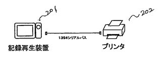
A description will be given when each device is connected by a 1394 serial bus cable as shown in FIG. The bus configuration in FIG. 1 is composed of a 101 recording / reproducing device, a 102 printer device, and a 103 personal computer (PC) connected by a 1394 serial bus drawn by a solid line, and each device is based on the specification of the 1394 serial bus. Data transfer. Here, the 101 recording / reproducing apparatus is a digital camera, a camera-integrated digital VTR, or the like that records and reproduces moving images or still images. Further, if the video data output from the recording / reproducing
[0062]
With reference to the bus configuration as shown in FIG. 1, the operation of the embodiment of the present invention will be described with reference to FIG. In FIG. 2, 101 is a recording / reproducing apparatus, 102 is a printer, and 103 is a PC.
In the recording / reproducing
[0063]
In the
[0064]
In the
As indicated by a broken line, the recording / reproducing
[0065]
<Operation Example of Image Processing System of
Next, the operation of the block diagram 2 will be described in order. In the following description, in order to eliminate complexity, the description of the configuration for sending the compressed image data as it is will be omitted. Further, the control of the recording / reproducing
[0066]
First, at the time of recording by the recording / reproducing
[0067]
At the time of reproduction, the recording / reproducing
[0068]
The
The
[0069]
The video data and command data input to the
[0070]
Next, regarding the operation of the
The print data input to the
[0071]
The
[0072]
As described above, when video data is transferred from the recording / reproducing
Next, processing in the
Video data transferred from the recording / reproducing
[0073]
In the
The video data to be transferred is uncompressed data in the present embodiment as in the printer, but if the
[0074]
The
[0075]
In this way, the transferred video data is taken into the
The above is the description of the block diagram 2.
<Example of Operation Flowchart in
Next, the operation at this time is shown as a flowchart in FIG. 6, read / write address control of the image
[0076]
First, on the
[0077]
A cycle at a certain timing is temporarily called a cycle Ci. Based on step S2 for determining the last printed end point address information in Ci-1 which is the previous cycle, and step S1, the start point address (SPA at Ci) and end point to be printed in the current cycle Ci. An address (EPA at Ci) is set (step S3). The sequential address information from the SPA to the EPA is used for reading the
[0078]
On the other hand, in parallel with the above-mentioned step S3, the start point address in the next cycle Ci + 1(SPA at Ci + 1)And endpoint address(EPA at Ci + 1)Step S7 is also started, and the address of the image data necessary for the next print cycle is transferred to the recording / reproducing
[0079]
The address data SPA and EPA data are the same as those shown in FIG.2, Figure 13Is transferred by selecting a predetermined position in the data field (4 × N bytes). In step S8 in the
[0080]
Note that after completion of printing in cycle Ci in step S6 described above, data indicating the completion of cycle printing is similarly transferred from the
[0081]
Data transfer of the image data itself from the recording / reproducing
As described above, from the
[0082]
In the description of FIG. 6, the address data to be printed next time is described as sending two address data of (SPA) data indicating the start point and data (EPA) indicating the end point. The data (SPA) to be indicated and the data (PCL) to indicate the length may be sent.
<Example of Transfer Data Configuration of
FIG. 10 shows an example of a data configuration such as specific address designation.
[0083]
In FIG. 10, among all 45 bits, a 2-bit WORD0 indicating a data transfer request, a 3-bit WORD1 indicating a memory type, and coordinates (x, y) which are spatial addresses of images for transferring image data to the memory are represented. An example in which the position data indicating the start point and the end point is 40 bits in total (WORD2 to WORD5) is shown. 10 bits of
[0084]
Table 1 below shows the assignment of WORD0 indicating the status of the data transfer request. (0, 0) (1, 1) indicates the presence or absence of a request, but (1, 0) indicates a state in which there is a data transfer request in the near future. This is determined by the vicinity of the end of printing or the read state of the image memory.
[0085]
[Table 1]
[0086]
[Table 2]
[0087]
[Table 3]
[0088]
[Embodiment 2]
As a second embodiment, a case where the performance of the printer engine is used as request data from the printer will be described. The performance of the printer engine indicates the printing capability of the printer determined by the
[0089]
For example, in the case of an ink jet printer, the printing resolution is determined by the interval between the ejection nozzles of the ink head, and is generally indicated by dpi (dot / inch) as the number of nozzles per inch. The higher the dpi value, the higher the resolution and the higher the printing quality. However, the amount of image data actually increases in proportion to the resolution, and the data transfer speed at the interface and the image data conversion on the printer side If the printing speed is not balanced, a wasteful waiting time will occur in either.
[0090]
FIG. 18 is a diagram showing the relationship between the print resolution and the amount of image data. When 100 dpi is 1, image data of 4 times at 200 dpi, 16 times at 400 dpi, and 64 times at 800 dpi is required, that is, compressed. It can be seen that the amount of data increases in proportion to the square of the resolution for image data that is not. FIG. 19 is a diagram showing the data size of 4 pixels in the 4: 4: 4, 4: 2: 2, 4: 1: 1 format of the image data expressed in YUV, and the luminance data Y is 8 bits. If the color difference data U and V are also 8-bit data, 4 bytes of 4: 4: 4 are 12 bytes, and 4 bytes of 4: 2: 2 are 8 bytes.,If it is 4: 1: 1 4 pixels, the data amount is 6 bytes. That is, by switching the data format, the total amount of image data can be reduced to 2/3 or 1/2.
[0091]
In other words, for printers with a high resolution of the printer engine, the image data format is switched to a mode for reducing the amount of data. Thus, the data amount of the entire image data can be made constant, and it becomes possible to limit the data packet size transferred at a time.
[0092]
Here, advantages of making the data packet size constant will be described.
As shown in FIG. 16, asynchronous transfer and isochronous transfer are mixed in the data transfer on the 1394 serial bus. The isochronous transfer can reserve the data band, whereas the asynchronous transfer is often waited for by the traffic on the serial bus. Even if a large number of asynchronous transfers are performed at this time, in order for the data transfer to be executed reliably, it is necessary that another data transfer does not occupy the bus, and conversely the printer occupies the bus. If this happens, other asynchronous transfer devices will not be able to transfer data. In other words, if it is a one-to-one connected system, there is no concern, but there is a great problem when a plurality of devices are connected on the same bus and each exchanges data. Therefore, by exchanging the resolution information of the printer engine before data transfer, the data format is switched according to the resolution, the transfer source node creates the image data and converts it into a data packet, and the transfer destination The node can more reliably receive image data and perform a printing operation.
[0093]
It is also possible to use a parameter called printing speed as printer engine information. That is, since the data processing time per unit time of the printer is a parameter, it has the same contents regardless of resolution or printing speed. In addition, the data packet size is constantConversionIf so, conversely, it is possible to set the print speed to be delayed when the resolution is increased, or to decrease the resolution when the print speed is increased.
[0094]
<Example of Transfer Data Configuration of
FIG. 20 is a diagram showing a specific bit structure of request data. First, a 2-bit WORD0 indicating a data transfer request, an 8-bit WORD6 indicating an image format type, and a resolution of the printer engine are shown. It consists of 32-bit WORD7 and 32-bit WORD8 representing the speed of the printer engine.
[0095]
WORD0 is a bit indicating the state of the data transfer request as in the first embodiment.
[0096]
Table 4 below shows an example of WORD6.
[0097]
[Table 4]
[0098]
Note that the present invention can be applied to a system including a plurality of devices (for example, a host computer, an interface device, a reader, a printer, etc.), or a device (for example, a copier, a facsimile device, etc.) including a single device. You may apply to.
Another object of the present invention is to supply a storage medium storing software program codes for implementing the functions of the above-described embodiments to a system or apparatus, and the computer (or CPU or MPU) of the system or apparatus stores the storage medium. Needless to say, this can also be achieved by reading and executing the program code stored in the.
[0099]
In this case, the program code itself read from the storage medium realizes the functions of the above-described embodiments, and the storage medium storing the program code constitutes the present invention.
As a storage medium for supplying the program code, for example, a floppy disk, a hard disk, an optical disk, a magneto-optical disk, a CD-ROM, a CD-R, a magnetic tape, a nonvolatile memory card, a ROM, or the like can be used.
[0100]
Further, by executing the program code read by the computer, not only the functions of the above-described embodiments are realized, but also an OS (operating system) operating on the computer based on the instruction of the program code. It goes without saying that a case where the function of the above-described embodiment is realized by performing part or all of the actual processing and the processing is included.
[0101]
Further, after the program code read from the storage medium is written into a memory provided in a function expansion board inserted into the computer or a function expansion unit connected to the computer, the function expansion is performed based on the instruction of the program code. It goes without saying that the CPU or the like provided in the board or the function expansion unit performs part or all of the actual processing, and the functions of the above-described embodiments are realized by the processing.
[0102]
When the present invention is applied to the above storage medium, the storage medium stores program codes corresponding to the processing procedure described above.
Further, in the present specification, the present invention has been described by taking an image processing system including a recording / reproducing apparatus, a printer, and a PC as an example. However, the present invention is a system in which devices having different data processing capabilities are connected by a general-purpose interface. However, the present invention is not limited to the image processing system, and the same effect can be obtained in other data processing systems.
[0103]
According to the first embodiment, when predetermined image data is sent from the transfer source node to the transfer destination node, data transfer is sequentially performed by the amount of the image data recording memory owned by the transfer destination node. By providing a system that sequentially transfers data corresponding to the spatial address of the image data required next by the transfer destination node as desired, without failure, the capacity and method of the storage memory of the transfer destination node It is possible to always provide a highly efficient transfer system regardless of the difference.
According to the second embodiment, a plurality of devices can be connected by selecting the resolution and format of image data according to the image data processing capability of the transfer destination node and arbitrarily setting the data packet size that can be transferred at one time. The data transfer efficiency on the serial bus can be improved.
【The invention's effect】
As described above, according to the present invention, from the transfer destination node to the transfer source node.,Data processing capacity of the destination nodePrior to transfer of data in a data format determined according to the address of the data requested by the transfer destination nodeBroadcast informationThe transfer destination node receives the data in the data format specified by the address information sent from the transfer source node in response to a signal accompanying the end of data processing in the transfer destination node.By doing so, it is possible to provide a data transfer method, an image processing system, and an apparatus that always perform highly efficient data transfer regardless of the difference in processing capability of the transfer destination node.
[Brief description of the drawings]
FIG. 1 is a diagram showing an example of a network according to a first embodiment of the present invention.
FIG. 2 is a block diagram of a recording / reproducing apparatus, a printer apparatus, and a PC to which
FIG. 3 is a block diagram showing a configuration when a digital camera, a PC, and a printer are connected with a PC as a center in a conventional example.
FIG. 4 is a diagram illustrating an area of a printer memory.
FIG. 5 is a diagram showing an example of a network according to a second embodiment of the present invention.
FIG. 6 is a flowchart showing a memory address setting operation in the first embodiment.
FIG. 7 is a diagram illustrating an example of a network configuration connected using a 1394 serial bus.
FIG. 8 is a diagram illustrating components of a 1394 serial bus.
FIG. 9 is a diagram showing an address map of a 1394 serial bus.
10 is a configuration diagram of request data according to
FIG. 11 is a coordinate diagram of an image spatial address.
FIG. 12 is a basic configuration diagram showing temporal state transition of asynchronous transfer.
FIG. 13 is a diagram illustrating an example of a packet format for asynchronous transfer.
FIG. 14 is a basic configuration diagram showing temporal state transition of isochronous transfer.
FIG. 15 is a diagram illustrating an example of a packet format for isochronous transfer.
FIG. 16 is a diagram illustrating a temporal transition of a transfer state on a bus.
FIG. 17 is a flowchart showing a flow from bus reset to node ID determination.
FIG. 18 is a relationship diagram between image data amount and resolution.
FIG. 19 is a diagram showing a configuration of a YUV data format.
20 is a configuration diagram of request data in
[Brief description of symbols]
8 Recording / playback system
9 System controller
13 memory
14 Memory control
18, 19, 61 1394 I / F
26 Printer controller
63 MPU
101, 201 recording / reproducing apparatus
102,202 Printer
103 PC (personal computer)
Claims (13)
転送先ノードが具備しているデータ処理能力に応じて決められるデータ形式のデータの転送に先立って、前記転送先ノードが要求するデータのアドレス情報を、前記転送先ノードから前記転送元ノードに報知し、
前記転送先ノードにおけるデータ処理の終了に伴う信号を、前記転送先ノードから前記転送元ノードに対して送信し、
前記データ処理の終了に伴う信号に応じて前記転送元ノードから送出された、前記アドレス情報で指定された前記データ形式のデータを、前記転送先ノードが受信することを特徴とするデータ転送方法。A data transfer method for transferring data from a transfer source node to a transfer destination node,
Prior to the transfer of data of the data format determined in accordance with the data processing capability of the destination node is provided, the broadcast address information of the data to the destination node requests, to the transfer source node from said destination node And
A signal accompanying the end of data processing in the transfer destination node is transmitted from the transfer destination node to the transfer source node,
The data transfer method , wherein the transfer destination node receives data in the data format specified by the address information sent from the transfer source node in response to a signal accompanying the end of the data processing .
転送先ノードが、
前記転送先ノードが具備しているデータ処理能力に応じて決められるデータ形式のデータの転送に先立って、前記転送先ノードの要求するデータのアドレス情報を、前記転送元ノードに報知する報知手段と、
前記転送先ノードにおけるデータ処理の終了に伴う信号を、前記転送元ノードに対して送信する送信手段と、
前記データ処理の終了に伴う信号に応じて前記転送元ノードから送出された、前記アドレス情報で指定された前記データ形式のデータを受信する受信手段とを有することを特徴とするシステム。A system consisting of a plurality of devices and transferring and processing data from a transfer source node to a transfer destination node between the plurality of devices,
The forwarding node is
Wherein prior to the transfer of data in the data format is determined according to the destination node data processing capabilities that are provided, the address information of the requested data of the transfer destination node, and informing means for informing the forwarding node ,
Transmitting means for transmitting a signal accompanying the end of data processing in the transfer destination node to the transfer source node;
Receiving means for receiving data in the data format specified by the address information sent from the transfer source node in response to a signal accompanying the end of the data processing .
前記画像処理装置が具備しているデータ処理能力に応じて決められるデータ形式の画像データの送信に先立って、前記画像処理装置から送信された、前記画像処理装置の要求する画像データのアドレス情報を受信する第1受信手段と、
前記画像処理装置における画像データ処理の終了に伴う信号を受信する第2受信手段と、
前記画像データ処理の終了に伴う信号の受信に応じて、前記アドレス情報で指定された前記データ形式の画像データを、前記画像処理装置へ送信する送信手段とを有することを特徴とする再生装置。A playback device capable of communicating with an image processing device ,
Prior to transmission of the image data of the data format determined in accordance with the data processing capacity by the image processing apparatus is equipped, the transmitted from the image processing apparatus, the address information of the requested image data of the image processing apparatus First receiving means for receiving;
Second receiving means for receiving a signal associated with completion of image data processing in the image processing apparatus;
A reproduction apparatus comprising: a transmission unit configured to transmit image data in the data format specified by the address information to the image processing apparatus in response to reception of a signal accompanying the end of the image data processing .
前記画像処理装置が具備しているデータ処理能力に応じて決められるデータ形式の画像データの受信に先立って、前記画像処理装置が要求する画像データのアドレス情報を、前記再生装置に報知する報知手段と、 Prior to receiving image data in a data format determined according to the data processing capability of the image processing device, notification means for notifying the playback device of address information of the image data requested by the image processing device When,
前記画像処理装置における画像データ処理の終了に伴う信号を、前記再生装置に対して送信する送信手段と、 Transmitting means for transmitting a signal accompanying the end of image data processing in the image processing apparatus to the reproduction apparatus;
前記画像データ処理の終了に伴う信号に応じて前記再生装置から送出された、前記アドレス情報で指定された前記データ形式の画像データを受信する受信手段を有することを特徴とする画像処理装置。 An image processing apparatus comprising: receiving means for receiving image data in the data format specified by the address information sent from the reproduction apparatus in response to a signal accompanying the end of the image data processing.
前記画像処理装置が具備しているデータ処理能力に応じて決められるデータ形式の画像データの受信に先立って、前記画像処理装置が要求する画像データのアドレス情報を、前記再生装置に報知し、 Prior to the reception of image data in a data format determined according to the data processing capability of the image processing device, the address information of the image data requested by the image processing device is notified to the playback device,
前記画像処理装置における画像データ処理の終了に伴う信号を、前記再生装置に対して送信し、 A signal accompanying the end of image data processing in the image processing device is transmitted to the playback device;
前記画像データ処理の終了に伴う信号に応じて前記再生装置から送出された、前記アドレス情報で指定された前記データ形式の画像データを受信することを特徴とする画像処理装置の制御方法。 A control method for an image processing apparatus, comprising: receiving image data in the data format specified by the address information sent from the reproduction apparatus in response to a signal accompanying the end of the image data processing.
Priority Applications (3)
| Application Number | Priority Date | Filing Date | Title |
|---|---|---|---|
| JP09230297A JP3774540B2 (en) | 1997-04-10 | 1997-04-10 | Data transfer method, image processing system and apparatus |
| EP98301121A EP0859326A3 (en) | 1997-02-14 | 1998-02-16 | Data transmission apparatus, system and method, and image processing apparatus |
| US09/025,129 US7062579B2 (en) | 1997-02-14 | 1998-02-17 | Data transmission apparatus, system and method, and image processing apparatus |
Applications Claiming Priority (1)
| Application Number | Priority Date | Filing Date | Title |
|---|---|---|---|
| JP09230297A JP3774540B2 (en) | 1997-04-10 | 1997-04-10 | Data transfer method, image processing system and apparatus |
Publications (2)
| Publication Number | Publication Date |
|---|---|
| JPH10285246A JPH10285246A (en) | 1998-10-23 |
| JP3774540B2 true JP3774540B2 (en) | 2006-05-17 |
Family
ID=14050625
Family Applications (1)
| Application Number | Title | Priority Date | Filing Date |
|---|---|---|---|
| JP09230297A Expired - Fee Related JP3774540B2 (en) | 1997-02-14 | 1997-04-10 | Data transfer method, image processing system and apparatus |
Country Status (1)
| Country | Link |
|---|---|
| JP (1) | JP3774540B2 (en) |
Families Citing this family (5)
| Publication number | Priority date | Publication date | Assignee | Title |
|---|---|---|---|---|
| JP3652125B2 (en) | 1998-07-10 | 2005-05-25 | キヤノン株式会社 | Imaging control apparatus, imaging control method, imaging control system, and storage medium |
| JP2000194527A (en) | 1998-12-28 | 2000-07-14 | Canon Inc | Image processing system and its control method |
| JP2004013349A (en) | 2002-06-04 | 2004-01-15 | Canon Inc | Imaging device, recording system, and recording control method thereof |
| JP4208640B2 (en) | 2002-06-04 | 2009-01-14 | キヤノン株式会社 | Printing system, printing control method, printing apparatus, and control method therefor |
| CN111966400A (en) * | 2019-05-20 | 2020-11-20 | 上海寒武纪信息科技有限公司 | Instruction processing method and device and related product |
-
1997
- 1997-04-10 JP JP09230297A patent/JP3774540B2/en not_active Expired - Fee Related
Also Published As
| Publication number | Publication date |
|---|---|
| JPH10285246A (en) | 1998-10-23 |
Similar Documents
| Publication | Publication Date | Title |
|---|---|---|
| US7062579B2 (en) | Data transmission apparatus, system and method, and image processing apparatus | |
| KR100311706B1 (en) | Data communication system, data communication method, data communication apparatus and digital interface | |
| CA2229472C (en) | Data communication apparatus and method | |
| JP3782542B2 (en) | Image processing apparatus and image processing system | |
| JP2000358033A (en) | Data communication system and data communication method | |
| US6237106B1 (en) | Communication apparatus and method, and program in computer readable medium | |
| JPH10187583A (en) | Device and method for data communication | |
| JPH11316657A (en) | Data transfer device, method thereof, data transfer system and medium | |
| JP2004030111A (en) | Apparatus, method, and system for information processing and storage medium | |
| US7002964B1 (en) | Communication system, method for a communication system and controller for a communication system | |
| JP3774540B2 (en) | Data transfer method, image processing system and apparatus | |
| KR100311707B1 (en) | Data communication system, data communication method, data communication apparatus, and digital interface | |
| JP4072215B2 (en) | Image processing apparatus, control method therefor, and image processing system | |
| JPH10285240A (en) | Data communication equipment and its method, data communication system and storage medium | |
| JP3501613B2 (en) | Data communication system, print system and data communication device | |
| JP3814407B2 (en) | Data communication system, data communication apparatus, and data communication method | |
| JP3862349B2 (en) | Information processing system, image processing system and method thereof, information processing apparatus, and computer-readable memory | |
| JP3890124B2 (en) | Data communication system, data communication method, data communication node, and recording medium | |
| JP3943698B2 (en) | Data communication system and data communication apparatus | |
| JP3943697B2 (en) | Data communication system, data communication apparatus, and data communication method | |
| JP2002144681A (en) | Information processor and processing method, and information processing system and storage medium | |
| JP2001147790A (en) | Device and method for processing information and storage medium | |
| JP2004030109A (en) | Apparatus and method for information processing and storage medium stored with program thereof | |
| JP2002064511A (en) | Data communication system, electronic device and method for controlling them | |
| JP2006050653A (en) | Data communication apparatus, method, and system, and storage medium |
Legal Events
| Date | Code | Title | Description |
|---|---|---|---|
| A977 | Report on retrieval |
Free format text: JAPANESE INTERMEDIATE CODE: A971007 Effective date: 20050421 |
|
| A131 | Notification of reasons for refusal |
Free format text: JAPANESE INTERMEDIATE CODE: A131 Effective date: 20050425 |
|
| A521 | Written amendment |
Free format text: JAPANESE INTERMEDIATE CODE: A523 Effective date: 20050624 |
|
| A131 | Notification of reasons for refusal |
Free format text: JAPANESE INTERMEDIATE CODE: A131 Effective date: 20051031 |
|
| A521 | Written amendment |
Free format text: JAPANESE INTERMEDIATE CODE: A523 Effective date: 20051228 |
|
| TRDD | Decision of grant or rejection written | ||
| A01 | Written decision to grant a patent or to grant a registration (utility model) |
Free format text: JAPANESE INTERMEDIATE CODE: A01 Effective date: 20060127 |
|
| A61 | First payment of annual fees (during grant procedure) |
Free format text: JAPANESE INTERMEDIATE CODE: A61 Effective date: 20060220 |
|
| R150 | Certificate of patent or registration of utility model |
Free format text: JAPANESE INTERMEDIATE CODE: R150 |
|
| FPAY | Renewal fee payment (event date is renewal date of database) |
Free format text: PAYMENT UNTIL: 20100224 Year of fee payment: 4 |
|
| FPAY | Renewal fee payment (event date is renewal date of database) |
Free format text: PAYMENT UNTIL: 20100224 Year of fee payment: 4 |
|
| FPAY | Renewal fee payment (event date is renewal date of database) |
Free format text: PAYMENT UNTIL: 20110224 Year of fee payment: 5 |
|
| FPAY | Renewal fee payment (event date is renewal date of database) |
Free format text: PAYMENT UNTIL: 20120224 Year of fee payment: 6 |
|
| FPAY | Renewal fee payment (event date is renewal date of database) |
Free format text: PAYMENT UNTIL: 20130224 Year of fee payment: 7 |
|
| FPAY | Renewal fee payment (event date is renewal date of database) |
Free format text: PAYMENT UNTIL: 20140224 Year of fee payment: 8 |
|
| LAPS | Cancellation because of no payment of annual fees |