JP4013492B2 - Magnetic field shielding device and biomagnetic field measuring device using the same - Google Patents
Magnetic field shielding device and biomagnetic field measuring device using the same Download PDFInfo
- Publication number
- JP4013492B2 JP4013492B2 JP2001086628A JP2001086628A JP4013492B2 JP 4013492 B2 JP4013492 B2 JP 4013492B2 JP 2001086628 A JP2001086628 A JP 2001086628A JP 2001086628 A JP2001086628 A JP 2001086628A JP 4013492 B2 JP4013492 B2 JP 4013492B2
- Authority
- JP
- Japan
- Prior art keywords
- magnetic field
- field shielding
- axis
- magnetic
- cylindrical member
- Prior art date
- Legal status (The legal status is an assumption and is not a legal conclusion. Google has not performed a legal analysis and makes no representation as to the accuracy of the status listed.)
- Expired - Fee Related
Links
Images


Landscapes
- Measuring Magnetic Variables (AREA)
- Measurement And Recording Of Electrical Phenomena And Electrical Characteristics Of The Living Body (AREA)
Description
【0001】
【発明の属する技術分野】
本発明は,検査対象から発生する磁場を,高感度な量子干渉素子(SQUID:superconducting quantum interference device)からなる複数の磁束計を用いて計測するための磁場遮蔽装置,及び,これを用いる磁場計測方法,磁場計測装置に関する。本発明は,特に,生体の心臓の心筋活動等により発生する生体磁場を計測するための磁場遮蔽装置,及び,これを用いる生体磁場計測方法,生体磁場計測装置に関する。
【0002】
【従来技術】
径の異なる複数の円筒形シールドを順次同芯状に配置し,各円筒形シールドの間に間隙を形成した磁気シールドが報告されている(従来技術1:特開平9−214166号公報)。
【0003】
従来技術1に記載の技術では,厚さ0.1mm〜0.5mm,幅20cm〜50cmのテープ状のパーマロイからなる磁気シールド材を用い,軽量なプラスチック円筒を芯として磁気シールド材をスパイラル状に巻きつけ,隙間なく重ね合わせたオーバーラップ部の幅を5cm〜10cmとって円筒形に形成されている。オーバーラップ部は,実質的に2層〜5層となり,その厚みの合計が0.5mm〜3mm程度となるようなスパイラル状に巻きつけられている。また,オーバーラップ部には,周方向の長さで30cm間隔にリベットが設けられ,締め付け固定され,オーバーラップ部の接着面は,金属と金属の接触となっている。
【0004】
なお,従来技術1には,従来の技術として,Ni−Fe系の高透磁率の合金材料であるパーマロイの板を多数枚用いてプレハブ部屋のようなシールドルームを製作するの記載があり,この従来技術には,磁気シールドの製作に長時間を要し,部品点数が多く,磁気シールドが非常に高価になるという問題があり,生体磁気計測機器の価格で磁気シールドの占める割合は大きく,磁気シールドの低価格化が望まれているとの記載がある。
【0005】
パーマロイの板の代わりに,磁気シールド材として,軟磁性アモルファス合金の膜とポリマーフィルムとを貼り合わせた磁気シールドシートを用いて,軽量なシールドルームを製作することが報告されている(従来技術2:特開平2000−077890号公報)。
【0006】
【発明が解決しようとする課題】
パーマロイの板を組合せてシールドルームを製作する従来技術,従来技術1では,加工後のパーマロイの焼鈍処理を必要とするという問題,広い面積を必要とするという問題,シールドルームの重量が大きくシールドルームを設置する場所に制限があるという問題,シールドルームが高価格となるという問題等があった。 従来技術2では,パーマロイの板を組合せてシールドルームを製作する従来技術1よりも,シールドルームの重量が軽量化され,低価格化が実現できるが,広い面積を必要とするという問題は解決されておらず,シールドルームのより軽量化,より低価格化が望まれていた。
【0007】
本発明の目的は,高透磁率を持つ高透磁率シートを用いて,軽量,小型の高性能な磁場遮蔽装置を低コストで提供し,検査対象,特に,生体から発生する磁場を計測するための磁場計測方法,磁場計測装置を提供することにある。
【0008】
【課題を解決するための手段】
本発明の代表的な磁場計測装置は,外来磁場の第1の方向に垂直な方向の成分が遮蔽される磁場遮蔽装置と,検査対象から発生する磁場の第1の方向に垂直な方向の成分を検出する複数のSQUID磁束計を低温に保持するクライオスタット,クライオスタットを保持する装置と,SQUID磁束計を駆動し,SQUID磁束計からの信号を検出する駆動検出回路と,駆動検出回路の出力を収集し演算処理を行なう演算処理装置と,演算処理装置の出力を表示する表示装置とから構成される。
【0009】
本発明の磁場遮蔽装置は,中空部をもつ非磁性の複数の筒形部材が第1の方向の軸を同心状に囲み配置され形成される。各筒形部材の面(内面又は/及び外面)に,高透磁率を持つ高透磁率シートの複数枚が,相互に一部分が重複するように貼付して配置される。
【0010】
最も内側に配置される筒形部材は,第1の方向の一端に第1の開口を,第1の方向の他端に第2の開口を持っている。第1の方向の軸に垂直な方向で複数の筒形部材を貫通する第3の開口が形成されている。最も内側に配置される筒形部材の内側の空間で,外来磁場の第1の方向に垂直な方向の成分が遮蔽される。最も内側に配置される筒形部材の内側の空間に,検査対象が生体である場合には,検査対象部位の体軸方向を第1の方向の軸にほぼ平行にして生体(被験者)を搭載する生体搭載装置(ベッド,椅子)が配置される。
【0011】
クライオスタットの一部が第3の開口に挿入され,クライオスタットの底面が内側の空間に配置される。第3の開口の直径を,クライオスタットの底面の直径よりも小さくして,クライオスタットの径が小さい部分を第3の開口に挿入する構成により,第3の開口の直径を大きくする必要がないので,外来磁場の磁場遮蔽率を向上させることができる。第3の開口は,検査対象が生体である場合には,生体(被験者)の胸面,又は,背面に対向し,クライオスタットの底面は,生体の胸面,又は,背面に対向して上記内側の空間に配置されている。
【0012】
クライオスタットの底面と検査対象の表面との位置関係は位置調整装置により調整され,第1の方向に垂直な方向で位置関係が調整される。位置調整装置は,第1の方向に垂直な第2の方向で,クライオスタットの位置,又は検査対象を搭載する搭載装置の位置を変化させることができる。更に,位置調整装置は,第1及び第2の方向に垂直な第3の方向,及び第1の方向で,搭載装置の位置を変化させることができる。
【0013】
更に,磁場遮蔽装置には,第1の方向の軸に垂直な方向で各筒形部材を貫通する第4の開口が形成されており,検査対象が生体である場合には,第4の開口は被験者の視野内にあり,開放感を被験者に与えている。
【0014】
【実施の形態】
以下の説明では,検査対象として,代表的な例として生体の心臓を対象として説明する。本発明は,生体の心臓に限定されるものではなく,例えば,一般の検査対象に含まれる磁性体の有無,磁性体の分布の検査にも適用できることは言うまでもない。本発明の装置の構成は大きな面積を必要としないので,例えば,磁性体を含む危険物の検査装置として使用でき,飛行場,港等での手荷物の検査にも適用可能である。
【0015】
本発明の磁場遮蔽装置では,非晶質又は多結晶質から構成される高透磁率の磁性材料の薄層を含み,柔軟性と薄い厚さを持つ複数の高透磁率シート,あるいは,Niを含む合金から構成される高透磁率の磁性材料を使用した複数の高透磁率シートが使用される。本発明で使用される高透磁率シートはフレキシブルである。
【0016】
複数の高透磁率シートは,中空部をもつ非磁性の2個から5個の筒形部材に高透磁率シートの一部分が重複して配置されている。複数の筒形部材は,第1の方向の軸を同心状に囲むように相互に固定され配置される。高透磁率シートには,磁性材料が配置される領域が,非磁性の保持シート(例えば,紙,高分子フィルム,金属フィルム)の間に挟まれて短冊の形状に形成され,複数の短冊は隣接する短冊の長辺で重複し,更に,複数の短冊の長辺がほぼ平行に配列されている。
【0017】
各高透磁率シートの複数の短冊の短辺は,第1の方向の軸にほぼ平行に配置され,高透磁率シートが複数の各筒形部材の面(内面又は/及び外面)に,各高透磁率シートの複数の短冊の長辺が第1の方向の軸を内側に取り囲むように貼付され,保持されている。このような短冊の形状を持つ磁性材料が配置される複数の領域を配置することにより,外来磁場の磁場遮蔽率を向上させている。
【0018】
最も内側に配置される筒形部材には,第1の方向の一端に第1の開口が,第1の方向の他端に第2の開口が形成されている。第1の方向の軸に垂直な方向で複数の筒形部材を貫通し,複数のSQUID磁束計を低温に保持するクライオスタットが挿入される第3の開口が形成されている。最も内側に配置される筒形部材の内側の空間で,外来磁場の第1の方向に垂直な方向の成分が遮蔽される。
【0019】
複数の筒形部材の第1の方向の軸に垂直な断面のより好ましい形状は,外来磁場の磁場遮蔽率を向上させる観点から,対称性が高い形状がより好ましく円とするが,円を第1の方向の軸に垂直な方向に,例えば,円の直径の約10%だけ押しつぶした形状でも良い。
【0020】
最も内側に配置される筒形部材の第1の方向の軸に垂直な断面のより好ましい形状は,直径が約50cm以上約200cm以下の円であり,最も内側に配置される筒形部材の内部に挿入される被験者に圧迫感を与えないようにする。小児を専用に検査する装置の場合には,もっと間も内側に配置される円筒部材の内径は約50cmであれば良く,小児,大柄な大人を検査対象とする装置の場合には,もっと間も内側に配置される円筒部材の内径は約50cmであれば良い。
【0021】
複数の非磁性の筒形部材として,磁場遮蔽装置の製作,コストの観点から,厚さ0.5mmから1mmをもつ,FRPの中空円筒,アルミニウムの中空円筒を使用するのがより好ましい。
【0022】
外来磁場の第1の方向に垂直な方向の成分が遮蔽される,最も内側に配置される筒形部材の内側の空間に,以下に示す3つの何れかの態様で被験者が楽な状態で置かれ,生体磁場を検出しようとする被験者の部位の体軸方向が第1の方向の軸にほぼ平行となるようにして,例えば,被験者の胸部,腹部内の胎児等から発生する生体磁場が検出される。
(1)第1の方向の軸を床面に対してほぼ水平とする場合には,被験者が横たわるベッドが,ほぼ水平の状態で,最も内側に配置される筒形部材の内部に配置される。
(2)第1の方向の軸を床面に対してほぼ垂直とする場合には,被験者は椅子に座っている状態で,最も内側に配置される筒形部材の内部に配置される。
(3)第1の方向の軸を水平面に対して角度が20度以上30度以下で傾斜させた場合には,被験者が横たわるベッドを傾斜させた状態で,あるいは,被験者が座っている椅子の背持たれの角度を傾斜させた状態で,最も内側に配置される筒形部材の内部に配置される。
【0023】
第3の開口及び/又は第4の開口は,以下の3つの何れかの態様で形成される。(1)各筒形部材に穴が開けられており,複数の筒形部材を,第1の方向の軸を同心状に囲むように相互に固定し一体化することにより,各筒形部材の穴により第3の開口が形成される。(1)の態様の他に,各筒形部材の一部分が移動可能に構成され,各筒形部材の一部分の移動により第3及び/又は第4の開口が形成される。
【0024】
即ち,各筒形部材の一部分が,第1の方向,第1の方向の軸を囲む周方向,第1の方向に交叉する方向の何れかの方向で移動可能であり,各筒形部材の一部分の移動により第3及び/又は第4の開口が形成される。具体的な態様を以下に示す。
(2)各筒形部材が第1の方向で,第1の部分と第2の部分との2つに分割される。第1及び第2の部分の各筒形部材はそれぞれ第1の方向の軸を同心状に囲むように相互に固定し一体化して構成される。第1の部分は第2の部分に対して第1の方向に移動して分離可能である。
【0025】
第1の部分の各筒形部材は,端部に開口する半円状の部分をもつ第1の切欠き部を持つ。第2の部分の各筒形部材は,端部に開口する半円状の部分をもつ第2の切欠き部を持つ。
【0026】
第1の部分の第2の部分に対する第1の方向での移動により,第1の部分の端部と第2の部分の端部とが第1の方向で重複する結果,第1及び第2の切欠き部により,第3及び/又は第4の開口が形成される。
【0027】
第1の部分の第2の部分に対する第1の方向の第1の移動に加え,更に,第1の方向に交叉する方向の第2の移動も可能である。第1の移動,あるいは,第1の移動及び第2の移動により,磁場遮蔽装置に開放部が形成される。
(3)各筒形部材が第1の方向の軸を囲む周方向で,第1の部分と第2の部分との2つに分割される。第1及び第2の部分の各筒形部材はそれぞれ相互に固定し一体化して構成される。第1の部分は第2の部分に対してを囲む周方向に移動可能に構成される。
【0028】
第1の部分の各筒形部材は,第1の方向にほぼ平行な1辺に開口する半円状の部分をもつ第1の切欠き部を持つ。第2の部分の各筒形部材は,第1の方向にほぼ平行な1辺に開口する半円状の部分をもつ第2の切欠き部を持つ。
【0029】
第1の部分の第2の部分に対する第1の方向の軸を囲む周方向での移動により,第1の部と第2の部分とが第1の方向の軸を囲む周方向で重複する結果,第1及び第2の切欠き部により,第3の開口が形成される。
【0030】
第1の部分と第2の部分は,第1の方向にほぼ平行な2辺でそれぞれ,第1の方向の軸を囲む周方向で約10度から約15度の範囲で重複する。第1の部分の移動により,第1の方向の軸を囲む周方向で約90度の範囲の開放部が,磁場遮蔽装置に形成される。
【0031】
磁場遮蔽装置の他の構成では,上記の(2),(3)で説明したように,各筒形部材が,第1の部分と第2の部分との2つに分割されて形成され,上記の第3の開口を形成するが,上記で説明した第3の開口を形成しない構成とする。クライオスタットの底部は,第1の開口,又第2の開口から挿入される。第4の開口は,被験者の検査対象部位から遠い位置に形成されるので,外来磁場の磁場遮蔽率を劣化させることはない。
【0032】
以下,本発明に於ける磁場計測の手順について説明する。
【0033】
まず,磁場遮蔽装置の各筒形部材の一部分を,第1の方向,第1の方向の軸を囲む周方向,第1の方向に交叉する方向の何れかの方向で移動させることにより,開放部を形成する。
【0034】
第1の方向の軸に交叉する方向から開放部を通して,生体が,磁場遮蔽装置の内側の空間に置かれる生体搭載装置(ベッド,椅子)に搭載される。あるいは,生体が搭載される生体搭載装置が,第1の方向の軸に沿って,第1の方向にほぼ平行な方向,又は,第1の方向の軸に交叉する方向から,開放部を通して磁場遮蔽装置の内側の空間に搬入される。
【0035】
次に,各筒形部材の一部分を,第1の方向,第1の方向の軸を囲む周方向,第1の方向に交叉する方向の何れかの方向の移動させることにより,開放部を閉鎖する。この結果,第3及び/又は第4の開口部が形成され,第3の開口部に,クライオスタットの一部が挿入された形となる。
【0036】
磁場遮蔽装置の内側の空間に配置されるクライオスタットの底面と,生体の表面との位置関係を,磁場信号が大きく検出されるように,第1の方向に垂直な方向で調整する。複数のSQUID磁束計により,生体から発生する磁場の第1の方向に垂直な方向の成分が検出される。
【0037】
本発明によれば,軽量,小型,低コストで高性能な,外来磁場の高い磁場遮蔽率を持つ磁場遮蔽装置を提供することができ,更に,この磁場遮蔽装置を用いる生体磁場を計測するための磁場計測方法,磁場計測装置を提供できる。
【0038】
また,本発明の磁場遮蔽装置は,軽量,小型であるため,設置する場所に耐加重性が特に要求されず,小さい面積があれば設置が可能であるので,磁場遮蔽装置,即ち,磁場計測装置を設置する場所に制限がなくなる。
【0039】
ここで,時間変数をt,生体の面を(x,y)面,生体の面に垂直な方向をz方向とする。クライオスタットの内部で底面の近傍に等間隔で2次元に格子状に配列されるSQUID磁束計の位置を(x,y),SQUID磁束計により検出される生体磁場の磁場成分(法線成分)をBz(x,y,t)とする。
【0040】
本発明の磁場計測装置では,生体磁場の接線成分Bx(x,y,t),By(x,y,t)をそれぞれ,計測された法線成分Bz(x,y,t)のx方向の変化率∂Bz(x,y,t)/∂x,y方向の変化率∂Bz(x,y,t)/∂yに比例する値として求める。比例定数を1とすると,接線成分Bx(x,y,t),By(x,y,t)は,(数1),(数2)によって与えられる。
【0041】
【数1】
Bx(x,y,t)=−(∂Bz(x,y,t)/∂x) …(数1)
【0042】
【数2】
By(x,y,t)=−(∂B(x,y,t)z/∂y) …(数2)
次に,x方向の変化率とy方向の変化率の2乗和の平方根に比例する値St(x,y,t)を求める。比例定数を1とすると,磁場波形St(x,y,t)は,(数3)によって与えられる。
【0043】
【数3】
St(x,y,t)=√[{∂Bz(x,y,t)/∂x}2+{∂Bz(x,y,t)/∂y}2] …(数3)
St(x,y,t)は,生体内部の磁場発生源を(x,y)面に投影した磁場強度情報を与える。tとして,Q,R,Sの各波のピーク位置をとり,St(x,y,t)のデータから内挿,外挿により同じ磁場強度を与える(x,y)点を結ぶ等磁場線図を求める。
【0044】
次に,各点(x,y)について任意の期間での磁場波形St(x,y,t)の積分値I(x,y)を(数4)により求め,内挿,外挿により積分値I(x,y)が同じ値の点を結ぶ等積分図を求める。
【0045】
積分範囲として,例えば,心臓を測定の対象とする時には,Q,R,Sの各波の発生する期間,Q波からS波の発生するQRS波(QRS complex)の期間,T波の発生する期間等をとる。
【0046】
【数4】
I(x,y)=∫│St(x,y,t)│dt …(数4)
更に,x,y,zの3方向の磁場成分を合成した磁場強度の時間波形V(x,y,t)を,(数5)により求めることにより,特に,胎児のように動きが激しい場合でも,安定した磁場波形を得ることができる。
【0047】
【数5】
V(x,y,t)=√[{∂Bz(x,y,t)/∂x}2+{∂Bz(x,y,t)/∂y}2+{Bz(x,y,t)}2]…(数5)
St(x,y,t)の代わり,V(x,y,t)を使用して,上記と同様にして,等磁場線図,等積分図を求めることができる。
【0048】
各SQUID磁束計により計測された磁場波形St(x,y,t),V(x,y,t)を表示すると共に,磁場分布図として,等磁場線図,等積分図を,表示装置の表示画面に表示する。等磁場線図,等積分図を,それらの等高線の高低により色分けをして3次元カラー表示して,診断に有用なデータを得ることができる。
【0049】
即ち,本発明の磁場計測装置では,接線成分Bx(x,y,t),By(x,y,t)を計測することなく,法線成分Bz(x,y,t)の計測のみから,電流源の直上にピークパターンが出現する磁場分布図を得ることができる。この結果,生体内の複数の電流源の位置を直読できるので,心筋梗塞,虚血,不整脈,心筋肥大等の診断,術前術後の心筋状態の変化の評価等の心臓に関する疾患の診断に有用なデータを得ることができる。本発明の磁場計測装置は,特に,成人,胎児の心臓の診断のためのデータ(磁場分布)を,10秒ないし5分程度の短時間で計測して表示できる。
【0050】
以下,より具体的に,代表的な実施例を図面を参照して詳細に説明する。
【0051】
図1は本発明の各実施例で使用される高透磁率を有する高透磁率シート23の構成例を説明する図である。図2は本発明の各実施例に於ける磁場遮蔽装置を構成する中空円筒への高透磁率シートの配置例を説明する斜視図である。図3は本発明の各実施例に於ける磁場遮蔽装置を構成する中空円筒への高透磁率シートの配置例を説明する断面図である。
【0052】
フレキシブルな高透磁率シート23は,短冊の形状の磁性材料(磁性材リボン,磁性材テープ)25が非磁性の保持シート26−1,26−2の間に挟まれて構成される。この高透磁率シート23は,従来技術2に記載される高透磁率シートと同じである。高透磁率材料として軟磁性アモルファス合金が使用される。
【0053】
短冊の形状の磁性材リボン25は,隣接する短冊の長辺で重複して配列され,複数の短冊の長辺はほぼ並行に配列さる。複数の磁性材リボン25は,保持シート26−1,26−2の間に可撓性を有する樹脂,又は接着剤24により固定されている。保持シート26−1,26−2の材質として代表的にPET(ポリエチレンテレフタレート)シートが使用される。高透磁率シート23の大きさは,例えば,縦450cm,横600cmである。
【0054】
軟磁性アモルファス合金は,最大比透磁率が50000以上であるFe−Cu−Nb−Si−B系(Fe:73.5%,Cu:1%,Nb:3%,Si:13.5%,B:9%)合金であり,結晶粒界の大きさが100nm以下の超微結晶組織をもっている。
【0055】
使用した磁性材リボン25の厚みは約20μm,保持シート26−1,26−2の厚さは30μmであり,高透磁率シート23の全厚は100μmである。磁性材リボン25の厚さを約10μm〜100μm,保持シート26−1,26−2の厚さを10μm〜500μmとし,高透磁率シート23の全厚を50μm〜1.5mmとすると,高透磁率シート23の貼付,折り曲げ作業が容易となる。
【0056】
本発明の各実施例に於ける磁場遮蔽装置は,同軸に配置される複数の磁場遮蔽円筒60から構成される。各磁場遮蔽円筒は,内半径の異なる高透磁率シート支持円筒80と,高透磁率シート支持円筒80の内周面及び/又は外周面に配置される高透磁率シート層82から構成される。
【0057】
各磁場遮蔽円筒には,各実施例に対応して,最も内側に配置される磁場遮蔽円筒の内部にクライオスタットの底面を挿入するための円形の第3の開口43が形成され,最も内側に配置される磁場遮蔽円筒の内部に配置される患者の視野内に,円形の第4の開口44が形成され,患者は医師と視線を合わせて対話ができる。
【0058】
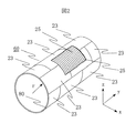
図2には1つの磁場遮蔽円筒60が示され,高透磁率シート支持円筒80の外周面に,複数の高透磁率シート23が接着剤等を用いて貼付されて高透磁率シート層82が形成されている。高透磁率シート支持円筒80は,内半径rの厚さ0.5mmのアルミニウムの中空円筒を使用している。
【0059】
高透磁率シート23の貼付は次ぎの何れかの方法による。(1)複数の高透磁率シート23が相互に重なり部分を持つように貼付する。(2)下層の高透磁率シート23の重ね部分を覆うように上層の高透磁率シー23を貼付する。(3)(1)の方法と(2)の方法とを組合せて貼付する。何れの貼付方法に於いても,高透磁率シート23の相互の重なりにより,磁性材リボン25の部分が相互に重なるように,複数の高透磁率シート23を重ねて貼付する。
【0060】
各高透磁率シート23は,各磁性材リボン25の短辺が高透磁率シート支持円筒80の中心軸にほぼ平行になるように,各磁性材リボン25の長辺が保持円筒21の中心軸を内側に取り囲み,高透磁率シート支持円筒80の中心軸に垂直な面にほぼ平行になるように,高透磁率シート支持円筒80に接着剤などを用いて貼付して,高透磁率シート23の複数層を形成する。
【0061】
図3は2層の高透磁率シート23により形成された高透磁率シート層82を示す。図3では第1層,第2層の各層での高透磁率シート23の重なりは省略している。
【0062】
本発明の各実施例に於ける磁場遮蔽装置は,同軸に配置される複数の磁場遮蔽円筒60のそれぞれを構成する高透磁率シート支持円筒80は異なる内半径を持つ。隣接する高透磁率シート支持円筒80の間隔は,1cmから20cmである。 以上説明した磁場遮蔽装置の構成により,外来磁場の複数の磁場遮蔽円筒60の中心軸に垂直方向の成分を,最も内側の磁場遮蔽円筒の内部で外来磁場を高い磁場遮蔽率で遮蔽する。以下の各実施例では,図面を単純化するために2個の磁場遮蔽円筒を持つ磁場遮蔽装置の構成を例示するが,2個から5個の磁場遮蔽円筒を持つ磁場遮蔽装置の構成としても良い。
【0063】
以下の各実施例の説明では,同軸に配置される複数の磁場遮蔽円筒60の中心軸を,簡単のために「磁場遮蔽装置の中心軸」と呼ぶ。更に,以下の各実施例の説明では,複数の磁場遮蔽円筒60の各円筒が,その中心軸の垂直方向で2個の部分に分割されて構成され,又は,その周方向で2個の部分に分割されて構成され,これら2個の部分を相互に重複させて,複数の磁場遮蔽円筒60の各円筒が構成される場合にも,重複させて構成され,共軸に配置される複数の磁場遮蔽円筒の中心軸を,同様に,「磁場遮蔽装置の中心軸」と呼ぶ。
(実施例1)
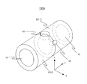
図4は本発明の実施例1の生体磁場計測装置の構成例を示す斜視図である。図5は図4に示す磁場遮蔽装置40の斜視図である。図6は図4に示す生体磁場計測装置の計測視野の中心を通る面での断面図である。
【0064】
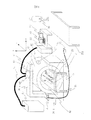
生体磁場計測装置は,磁場遮蔽装置40,検査対象(生体)から発生する磁場(生体磁場)を検出する複数のSQUID磁束計57を低温に保持するクライオスタット50と,クライオスタット50を支持するガントリ30−2と,磁場遮蔽装置40及びガントリ30−2を支持する磁場遮蔽装置・ガントリ支持台30−1と,クライオスタット50の内部を冷却するための冷媒供給装置又は冷却装置55及び冷媒供給線又は冷却伝達線54,データ収集・センサ制御線51を介してSQUID磁束計57を駆動制御し検出された生体磁場を収集しデータ処理を行なうデータ収集処理・センサ制御装置52と,データ処理の結果を表示する単数又は複数の表示装置53から構成される。
【0065】
クライオスタット50の内部は,冷媒供給線54を介して冷媒供給装置55から供給される液体Heにより冷却されるか,又は,冷却装置55として冷凍機を使用してコンプレッサにより冷却伝達線54を介して冷却されたHeガスをクライオスタット50の内部に配置されるコールドヘッドに供給して冷却される。
【0066】
磁場遮蔽装置40は,図2,図3で説明した複数の磁場遮蔽円筒60から構成され,複数の磁場遮蔽円筒の中心軸(y方向)の正方向に第1の開口41を,y方向の負方向に第2の開口42を,中心軸に垂直方向(z方向)の上部にクライオスタット50を挿入するための,複数の磁場遮蔽円筒を貫通する第3の開口43を,ベッド20に横たわる検査対象を観察するための,複数の磁場遮蔽円筒を貫通する第4の開口44をそれぞれ有する。複数の磁場遮蔽円筒の中心軸(y方向)(磁場遮蔽装置40の中心軸)は床面に水平である。
【0067】
磁場遮蔽装置40は,外来磁場の磁場遮蔽装置40の中心軸に垂直方向の成分を,最も内側の磁場遮蔽円筒60−1の内部で,高い磁場遮蔽率で遮蔽する。この結果,SQUID磁束計57は,磁場遮蔽装置2の内部で発生する生体磁場のz方向の成分を高感度で検出できる。
【0068】
ガントリ30−2の高さはガントリの高さ制御装置31により制御固定され,検査者(医師)35は,第4の開口44からベッド20に横たわる検査対象(患者)36の検査部位とクライオスタット50の底面との位置関係を観察しながら,ガントリの高さ制御ボックス32を操作する。ガントリの高さ制御ボックス32からの信号により,ガントリの高さ制御装置31が制御され,クライオスタット50の底面のz方向の位置が固定される。x方向はy方向及びz方向に直交する方向に設定される。
【0069】
クライオスタット102の内部の底部近傍にxy面に平行な面(計測面)に配置される複数のSQUID磁束計57は,データ収集処理・センサ制御装置52のFLL回路によって駆動される。FLL回路は,SQUID磁束計57で検出された生体磁場信号を出力する。FLL回路の出力は,フィルタリング,増幅され,AD変換器によってデジタルデータに変換され,データ収集処理・センサ制御装置52の記憶装置に保存される。データ収集処理・センサ制御装置52によりデータ処理された結果,例えば,磁場波形St(x,y,t)((数3)),V(x,y,t)((数5))による等磁場線図,等積分図等が,表示装置53の表示画面に表示される。
【0070】
検査対象36が搭載されるベッド20はx及びy方向移動装置21に搭載されており,x及びy方向移動装置21はx及びy方向移動装置の支持台22に固定されている。ベッド20は磁場遮蔽装置40の最も内側の磁場遮蔽円筒の内部に配置される。
【0071】
なお,クライオスタット50の底面の高さを固定された位置として,x及びy方向移動装置21の代りに,x,y,z方向移動装置を使用することもできる。この場合には,ガントリ30−2と磁場遮蔽装置40との位置関係が,複数のSQUID磁束計57の検出コイルが配列される計測面がもっとも内側の磁場遮蔽円筒60−1の中心軸にほぼ一致するように,ガントリ30−2の位置が固定される,又は,ガントリ30−2と磁場遮蔽装置・ガントリ支持台30−1とが一体で構成される。勿論,ガントリの高さ制御装置31,ガントリの高さ制御ボックス32は不要となる。
【0072】
検査者(医師)35は,第4の開口44からベッド20の上の検査対象(患者)36の検査部位とクライオスタット50の底面との位置関係を観察しながら,ガントリの高さ制御ボックス32に代えて,ベッド20のx,y,z方向移動制御ボックス(図示せず)を操作する。x,y,z方向移動制御ボックスからの信号により,ベッド20のx,y,z方向移動装置が制御され,ベッド20のx方向,y方向及びz方向の位置が固定される。
【0073】
以上の説明では,検査者(医師)35が,第4の開口44を通して患者36を観察したが,第4の開口44を設けない構成として,第1の開口41又は第2の開口42を通して患者36を観察しても良いことは言うまでもない。
【0074】
患者36の視野内に設けられる第4の開口44は,患者36に開放感を与えるとともに,検査者(医師)35は,第4の開口44を通して患者36と近いで対話ができ,正確に患者の状態を観察できる。検査者(医師)35は,患者36への指示を容易に伝達できる。患者36は第4の開口44を通して磁場遮蔽装置40の外部を見ることができ,心理的な不安感等を低減する効果がある。
【0075】
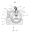
図5に示すように,複数の磁場遮蔽円筒を貫通する第3の開口43の中心軸と,複数の磁場遮蔽円筒を貫通する第4の開口44の中心軸とは,約45度の角度をなしている。図6に示すように,クライオスタット50の内部の底部には,SQUID磁束計57が2次元に配列され,クライオスタット50の内部は冷媒56が満たされている。
【0076】
磁場遮蔽円筒60は,第1の磁場遮蔽円筒60−1,第2の磁場遮蔽円筒60−2から構成される。第1の磁場遮蔽円筒60−1と第2の磁場遮蔽円筒60−2との間には,充填剤70が充填され,第1の磁場遮蔽円筒60−1,第2の磁場遮蔽円筒60−2の形状を安定に保持している。図6に示す例では,充填剤70を下半分に充填しているが,更に,第3の開口43,第4の開口44を除く上半分の部位にも充填しても良い。充填剤70としては,発泡剤を含む硬質ポリウレタン等が使用できる。発泡剤を含む硬質ポリウレタンは,軽量なので第3の開口43,第4の開口44を除く上半分の部位にも充填しても,第1の磁場遮蔽円筒60−1,第2の磁場遮蔽円筒60−2の形状を変形させることはない。
(実施例2)
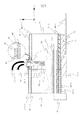
図7は本発明の実施例2の生体磁場計測装置の構成例を示す斜視図である。図8は図7に示す磁場遮蔽装置の斜視図である。図9は図7に示す生体磁場計測装置の計測視野の中心を通る面での断面図であり,一部拡大断面を含む。
【0077】
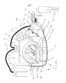
以下,実施例1との相違点を中心に説明する。実施例2の生体磁場計測装置の構成では,実施例1で説明した磁場遮蔽装置40を,y方向で2分割して,磁場遮蔽装置の第1の部分40−1,磁場遮蔽装置の第2の部分40−2により構成する。磁場遮蔽装置の第1の部分40−1は,磁場遮蔽装置の第2の部分40−2に対して,y方向に移動可能な構成とする。実施例1と同様に,ガントリ30−2,磁場遮蔽装置の第2の部分40−2は,磁場遮蔽装置・ガントリ支持台30−1に支持される。
【0078】
磁場遮蔽装置の第1の部分40−1は,磁場遮蔽装置支持台92に支持固定され,磁場遮蔽装置支持台92の下部に配置される複数の車輪91は,床117の面に配置されたレール90−1,90−2の上に搭載されている。磁場遮蔽装置の第1の部分40−1は,レール90−1,90−2の上でy方向に移動できる。この移動により磁場遮蔽装置の第1の部分40−1と磁場遮蔽装置の第2の部分40−2とを分離できる。
【0079】
この結果,開放された空間で,医師35は楽な姿勢で患者36をベッド20に搭載でき,又は,患者36は楽にベッド20横たわることができる。患者は,足部が先にクライオスタットの下部を通過し,最終的に胸部がクライオスタットの下部に到達するように搭載される。医師35は,患者36の検査部位とクライオスタット50の底面との位置関係を,効率良く調整できる。調整後,分離された磁場遮蔽装置の第1の部分40−1を移動させて,磁場遮蔽装置の第1の部分40−1と磁場遮蔽装置の第2の部分40−2とをy方向で重複させて,第3の開口43,第4の開口44を形成できる。
【0080】
この結果,外来磁場の磁場遮蔽装置40の中心軸に垂直方向の成分を,最も内側の磁場遮蔽円筒40−1−1,40−2−1の内部で,高い磁場遮蔽率で遮蔽できる。高い磁場遮蔽率で外来磁場が遮蔽された空間で,検査部位からの生体磁場のz方向の成分を高感度で検出できる。
【0081】
図8に示すように,磁場遮蔽装置の第1の部分40−1を構成する磁場遮蔽円筒,磁場遮蔽装置の第2の部分40−2を構成する磁場遮蔽円筒はそれぞれ,重複させた時に第3の開口43,第4の開口44を形成するように,円周の一部をもつ切欠き部分を持っている。
【0082】
図9に示すように,磁場遮蔽装置40は,磁場遮蔽装置の第1の部分40−1,磁場遮蔽装置の第2の部分40−2とから構成される。磁場遮蔽装置の第1の部分40−1は,第1の磁場遮蔽内側円筒40−1−1,第1の磁場遮蔽外側円筒40−1−2とから構成される。磁場遮蔽装置の第2の部分40−2は,第2の磁場遮蔽内側円筒40−2−1,第2の磁場遮蔽外側円筒40−2−2とから構成される。
【0083】
第2の磁場遮蔽外側円筒40−2−2の内側に,第1の磁場遮蔽外側円筒40−1−2が重複して配置され,第2の磁場遮蔽内側円筒40−2−1の内側に,第1の磁場遮蔽内側円筒40−1−1が重複して配置される。図9にはこの重複部分に第3の開口が示されている。
【0084】
拡大断面に示すように,第2の磁場遮蔽内側円筒40−2−1,第2の磁場遮蔽外側円筒40−2−2の各高透磁率シート支持円筒80の内側に,高透磁率シート23により高透磁率シート層82が形成されている。第1の磁場遮蔽内側円筒40−1−1,第1の磁場遮蔽外側円筒40−1−2の各高透磁率シート支持円筒80の外側に,高透磁率シート23により高透磁率シート層82が形成されている。この結果,重複部分で,高透磁率シート層82を近接させる構成として,漏れ磁束を減少させて磁場遮蔽効果を高めている。
【0085】
また,磁場遮蔽装置40の中心軸に平行な方向で第3の開口の外側に於ける,第2の磁場遮蔽外側円筒40−2−2と第1の磁場遮蔽外側円筒40−1−2とが重複する距離,第2の磁場遮蔽内側円筒40−2−1と第1の磁場遮蔽内側円筒40−1−1とが重複する距離は,第3の開口の直径の約1/2から約1/4とする。重複部分を充分大きくして磁場遮蔽効果を高めている。
【0086】
ベッド20,x及びy方向移動装置21を搭載するベッド及び移動装置の支持台22は,スペーサ140−1を介して第2の磁場遮蔽内側円筒40−2−1の内部に配置される。実施例1と同様の目的で,第2の磁場遮蔽内側円筒40−2−1と第2の磁場遮蔽外側円筒40−2−2との間の下半分に,充填剤70−1が充填され,第1の磁場遮蔽内側円筒40−1−1と第1の磁場遮蔽外側円筒40−1−2間の下半分に,充填剤70−2が充填されている。図9示す例では,充填剤70−1,70−2を下半分に充填しているが,更に,第3の開口43,第4の開口44を除く上半分の部位にも充填しても良いことは言うまでもない。
【0087】
なお,実施例1と同様に,クライオスタット50の底面の高さを固定された位置として,x及びy方向移動装置21の代りに,ベッド20のx,y,z方向移動装置を使用できるとは言うまでもない。更に,実施例1と同様に,第4の開口がない構成としても良いことは言うまでもない。
(実施例3)
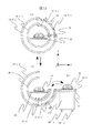
図10は本発明の実施例3の生体磁場計測装置の構成例を示す斜視図である。図11は図10に示す磁場遮蔽装置の斜視図であり,一部拡大断面を含む。図12は図7に示す生体磁場計測装置への検査対象(患者)の出し入れを説明する断面図であり,一部拡大断面を含む。
【0088】
以下,実施例1との相違点を中心に説明する。実施例1で説明した磁場遮蔽装置40を,周方向で2分割して,磁場遮蔽装置の第1の部分40−3,磁場遮蔽装置の第2の部分40−4により構成する。磁場遮蔽装置の第1の部分40−3は,磁場遮蔽装置の第2の部分40−4に対して,周方向に移動可能な構成とする。実施例1と同様に,ガントリ30−2,磁場遮蔽装置の第2の部分40−4は,磁場遮蔽装置・ガントリ支持台30−1に支持される。
【0089】
図11,図12に示すように,磁場遮蔽装置の第1の部分40−3は,y方向の正方向及び負方向の端部で結合板150−1により結合された,第1の磁場遮蔽内側円筒40−3−1,第2の磁場遮蔽外側円筒40−3−2から構成される。同様に,磁場遮蔽装置の磁場遮蔽装置の第2の部分40−4は,y方向の正方向及び負方向の端部で結合板150−2(図示せず)により結合された,第2の磁場遮蔽内側円筒40−4−1,第2の磁場遮蔽外側円筒40−4−2から構成される。図10,図11,図12に示すように,第1の磁場遮蔽内側円筒40−3−1,第2の磁場遮蔽外側円筒40−3−2を貫通する第4の開口40が形成されている。
【0090】
第4の開口40の第1の磁場遮蔽内側円筒40−3−1の内側,及び,第2の磁場遮蔽外側円筒40−3−2の外側はそれぞれ,透明な曲面板でカバーがされており,磁場遮蔽装置の第1の部分40−3の,磁場遮蔽装置の第2の部分40−4に対する周方向の移動の時,手,着衣等を挟み込まないようにしている。
【0091】
磁場遮蔽装置の第1の部分40−3は約110度の円周部を持ち,磁場遮蔽装置の第2の部分40−4は約270度の円周部を持ち,相互に両端部でそれぞれ約10度の範囲で重複する構成とする。即ち,第1の磁場遮蔽内側円筒40−3−1と第2の磁場遮蔽内側円筒40−4−1,及び,第2の磁場遮蔽外側円筒40−3−2と第2の磁場遮蔽外側円筒40−4−2はそれぞれ,磁場遮蔽装置の中心軸に平行な両端部で約10度の範囲で重複する時,閉じた状態の磁場遮蔽装置を形成し,約110度の範囲で重複する時,開口部を有し,開放された状態の磁場遮蔽装置を形成する。閉じた状態で重複部分を充分大きくして磁場遮蔽効果を高めている。
【0092】
第2の磁場遮蔽外側円筒40−3−2の高透磁率シート支持円筒80の外面の周面には,拡大断面に示すようにTの字型の細長い板がガイド105−2として配置されており,第2の磁場遮蔽外側円筒40−4−2の高透磁率シート支持円筒80の内面の周面にガイド105−2を受け入れるTの字型の細長い溝が形成されている。
【0093】
同様に,第1の磁場遮蔽内側円筒40−3−1の高透磁率シート支持円筒の外面の周面には,Tの字型の細長い板がガイド105−1として配置されており,第2の磁場遮蔽内側円筒40−4−1の高透磁率シート支持円筒の内面の周面にガイド105−1を受け入れるTの字型の細長い溝(図示せず)が形成されている。
【0094】
なお,高透磁率シート23により高透磁率シート層82は,第2の磁場遮蔽内側円筒40−4−1,第2の磁場遮蔽外側円筒40−4−2の各高透磁率シート支持円筒の外面に,第1の磁場遮蔽内側円筒40−3−1,第2の磁場遮蔽外側円筒40−3−2の各高透磁率シート支持円筒の内面に,それぞれ形成されている。
【0095】
図11に示すように,磁場遮蔽装置の第1の部分40−3を構成する磁場遮蔽円筒,磁場遮蔽装置の第2の部分40−4を構成する磁場遮蔽円筒はそれぞれ,重複させた時に第3の開口43を形成するように,円周の一部をもつ切欠き部分を持っている。
【0096】
図12(a)は,ベッド20に患者36が横たわり,検査部位からの生体磁場が計測される時の状態を示す。磁場遮蔽装置の第1の部分40−3を構成する磁場遮蔽円筒,磁場遮蔽装置の第2の部分40−4を構成する磁場遮蔽円筒はそれぞれ重複している。第1の部分40−3と第2の部分40−4の位置関係はロックにより固定されている。この状態で,外来磁場の磁場遮蔽装置40の中心軸に垂直方向の成分を,最も内側の磁場遮蔽円筒40−3−1,40−4−1の内部で,高い磁場遮蔽率で遮蔽できる。高い磁場遮蔽率で外来磁場が遮蔽された空間で,検査部位からの生体磁場のz方向の成分を高感度で検出できる。
【0097】
図12(b)は,磁場遮蔽装置の第1の部分40−3が,第1の部分40−3に取り付けた取っ手(図示せず)を用いて手動で,又は自動で,周方向に移動され,第1の部分40−3の位置がロックされ,開口部が形成され,約90度の角度範囲で開放空間が形成された状態を示す。この結果,開放空間で,医師35は楽な姿勢で,ベッド移動台103から患者36をベッド20に搭載でき,もしくは,患者36は楽にベッド20横たわることができ,医師35は,患者36の検査部位とクライオスタット50の底面との位置関係を,効率良く調整できる。
【0098】
なお,実施例1と同様に,クライオスタット50の底面の高さを固定された位置として,x及びy方向移動装置21の代りに,ベッド20のx,y,z方向移動装置を使用できるとは言うまでもない。更に,実施例1と同様に,第4の開口がない構成としても良いことは言うまでもない。
(実施例4)
本発明の実施例4の生体磁場計測装置は,実施例3の生体磁場計測装置の構成の一部を変更した,病室のベッドの近傍まで移動可能な構成としたベッドサイド用生体磁場計測装置である。
【0099】
磁場遮蔽装置・ガントリ支持台30−1には,移動可能なように複数個の車輪100が配置されており,また,ベッド及び移動装置の支持台22にも移動可能なように複数個の車輪29−1,29−2,29−3,29−4(図示せず)が配置されている。複数個の100−1を持つ台車に,データ収集処理・センサ制御装置52,表示装置53,冷媒供給装置又は冷却装置55が搭載される。
【0100】
実施例4のベッドサイド用生体磁場計測装置では,クライオスタット50の底面の高さを固定された位置として,x及びy方向移動装置21の代りに,ベッド20のx,y,z方向移動装置21’を使用する。
【0101】
図12(c)に示すように,車輪29’−1,29’−2,29’−3(図示せず),29’−4(図示せず)を持ち,搭載するベッド移動台103の近傍に,ベッドサイド用生体磁場計測装置を移動させた後,図12(b)に示すように,磁場遮蔽装置の第1の部分40−3が周方向に移動されその位置がロックされ,約90度の角度範囲で,開放空間が形成された状態とする。
【0102】
ベッドサイド用生体磁場計測装置のベッド20のx,y,z方向移動装置21’と,ベッド移動台10のベッド20−1,x,y,z方向移動装置21’とを使用して,x,y,z方向の各方向での,ベッド20及びベッド20−1の位置を調整して,容易に患者36をベッド20−1からベッド20に移動させることができる。
【0103】
ベッド20−1,x,y,z方向移動装置21’を使用して,医師35は,患者36の検査部位とクライオスタット50の底面との位置関係を調整する。その後,図12(a)に示す状態で,患者36の検査部位からの生体磁場が計測される。生体磁場の計測終了後,図12(b)に示す状態として,ベッド20のx,y,z方向移動装置21’と,ベッド移動台10のベッド20−1,x,y,z方向移動装置21’とを使用して,x,y,z方向の各方向での,ベッド20及びベッド20−1の位置を調整して,容易に患者36をベッド20からベッド20−1に移動させることができる。
【0104】
実施例4のベッドサイド用生体磁場計測装置は,自由に移動でき,病院内を移動して入院患者のベッドサイドでの検査が可能となる。従って,救急患者,ベッドに寝たきりの患者を測定する際,患者は,生体磁場計測装置が設置された検査室へ移動する必要がなく,患者の負担が軽減される。
(実施例5)
図13は本発明の実施例5の実施例であり,実施例3又は実施例4で説明した生体磁場計測装置を自動車に搭載した検診車(移動式生体磁場計測装置)の例を示す一部破断部を含む斜視図である。生体磁場計測装置の全体が,車内の床110に置かれた除振台111の上に配置固定され,外部の振動を遮断している。自動車は,固定用のアンカー112を備えており,生体磁場の計測の時にはアンカー112を地面に下ろして自動車を地面に固定する。この検診車は,学校,保健所等の地域コミュニティーへ移動して定期的な集団検診等に利用される。
(実施例6)
図14は本発明の実施例6の生体磁場計測装置に使用される磁場遮蔽装置の構成例を示す斜視図であり,一部拡大を含む。図15は,図14に示す磁場遮蔽装置を使用する生体磁場計測装置の計測視野の中心を通る面での断面図である。
【0105】
図14に示す磁場遮蔽装置は,実施例1で説明した磁場遮蔽装置40を周方向で2分割して,磁場遮蔽装置の第1の部分40−5,磁場遮蔽装置の第2の部分40−6により構成する。磁場遮蔽装置の第1の部分40−5は,磁場遮蔽装置の第2の部分40−6に対して周方向に移動可能な構成とする。
【0106】
第2の磁場遮蔽内側円筒40−6−1,第2の磁場遮蔽外側円筒40−6−2の下部には複数の車輪118が固定されており,図14の拡大断面の示すように,車輪118は,床117に形成された移動ガイド溝119の内部に配置されている。第2の磁場遮蔽内側円筒40−6−1,第2の磁場遮蔽外側円筒40−6−2の上部は結合板115により結合されている。結合板115にには,天井に配置される円形のガイドレールに連結させるための移動のための上部結合部116が固定されている。
【0107】
図14の拡大断面に示すように,第2の磁場遮蔽内側円筒40−6−1,第2の磁場遮蔽外側円筒40−6−2の各高透磁率シート支持円筒80の内側に,高透磁率シート23により高透磁率シート層82が形成されている。第1の磁場遮蔽内側円筒40−5−1,第1の磁場遮蔽外側円筒40−5−2の各高透磁率シート支持円筒80の外側に,高透磁率シート23により高透磁率シート層82が形成されている。この結果,重複部分で,高透磁率シート層82を近接させる構成として,漏れ磁束を減少させて磁場遮蔽効果を高めている。
【0108】
図15に示すように,第1の磁場遮蔽内側円筒40−5−1は磁場遮蔽円筒支持体128により,第2の磁場遮蔽外側円筒40−5−2は磁場遮蔽円筒支持体120により,それぞれ床117に固定される。SQUID磁束計57が2次元に配列される側のクライオスタット50−1は,ガントリ124に移動可能に固定される。x,y方向にそれぞに移動可能な椅子122に座った患者36の検査部位と,SQUID磁束計57が配列される側のクライオスタット50−1の面との位置関係,クライオスタット50−1の高さ位置が調整された後に,クライオスタット50−1は,クライオスタット位置固定ロック126により固定される。
【0109】
磁場遮蔽装置の第2の部分40−6の高さは,磁場遮蔽装置の第1の部分40−5の高さよりも高くして,磁場遮蔽装置の第2の部分40−6を回転させるための構造を単純にする。磁場遮蔽装置の第2の部分40−6は約200度の円周部を持ち,磁場遮蔽装置の第1の部分40−5は180度の円周部を持ち,相互に両端部でそれぞれ約10度の範囲で重複する構成とする。即ち,第1の磁場遮蔽内側円筒40−5−1と第2の磁場遮蔽内側円筒40−6−1,及び,第2の磁場遮蔽外側円筒40−5−2と第2の磁場遮蔽外側円筒40−6−2はそれぞれ,磁場遮蔽装置の中心軸に平行な両端部で約10度の範囲で重複する時,閉じた状態の磁場遮蔽装置を形成し,約180度の範囲で重複する時,開放された状態の磁場遮蔽装置を形成する。
【0110】
閉じた状態で重複部分を充分大きくして磁場遮蔽効果を高めて,外来磁場の磁場遮蔽装置40の中心軸に垂直方向の成分を,最も内側の磁場遮蔽円筒40−5−1,40−6−1の内部で,高い磁場遮蔽率で遮蔽できる。高い磁場遮蔽率で外来磁場が遮蔽された空間で,検査部位からの生体磁場のx方向の成分を高感度で検出できる。
【0111】
磁場遮蔽装置の第2の部分40−6を回転させて開放空間を作り,患者36が椅子122に座った状態で,医師は,患者36の検査部位とクライオスタット50−1の外面との位置関係を調整する。
【0112】
実施例6で使用する磁場遮蔽装置を構成する各磁場遮蔽円筒60の中心軸は共軸に配置され,各磁場遮蔽円筒は中心軸に対して平行な面で分割されている。各磁場遮蔽円筒は垂直に配置される。実施例6で使用する磁場遮蔽装置では,患者36は,容易に磁場遮蔽装置の内部に入ることができ,検査部位の位置合わせ効率よくできる。実施例6で使用する磁場遮蔽装置は小型であり,生体磁場計測装置の設置面積が小さくてすむ。
【0113】
なお,クライオスタット50−1の高さを固定された位置として,x及びy方向移動装置の代りに,検査対象36が座る椅子122のx,y,z方向移動を制御するx,y,z方向移動装置を使用して,SQUID磁束計57が配列される側のクライオスタット50−1の面と検査対象36の検査部位の面との位置合わせを行なうことができるとは言うまでもない。
(実施例7)
図16は本発明の実施例7であり,図14,図15に示す磁場遮蔽装置を使用する生体磁場計測装置の計測視野の中心を通る面での断面図である。実施例7の生体磁場計測装置では,図14,図15に示す磁場遮蔽装置を,床117に対して20度以上30度以下で傾斜している床117−1に配置する。その他の構成は,実施例6と同じである。
(実施例8)
図17は本発明の実施例8の生体磁場計測装置の構成例を示す斜視図である。図18は図17に示す生体磁場計測装置の計測視野の中心を通る面での断面図である。
【0114】
以下,実施例1との相違点を中心に説明する。磁場遮蔽装置40−7は,磁場遮蔽内側円筒40−7−1,磁場遮蔽外側円筒40−7−2から構成され,磁場遮蔽装置40−7は,床117に固定される磁場遮蔽装置支持体130により保持されている。
【0115】
実施例8では,磁場を検出する検出コイルが薄膜で掲載される平面型のSQUID磁束計を使用するので小型のクライオスタットを使用できる。実施例8では,実施例1で説明した磁場遮蔽装置40の構成で,クライオスタット50を挿入する第3の開口43を形成せず,SQUID磁束計が底部に2次元に配置されるクライオスタット50−2を磁場遮蔽内側円筒40−7−1の内部に配置する。クライオスタット50−2は,クライオスタット保持板132により保持され,クライオスタット保持板132は,床117に固定されるクライオスタット保持板の固定台131に保持される。
【0116】
ベッド20,x及びy方向移動装置21を搭載するベッド及び移動装置の支持台22は,スペーサ140−2を介して磁場遮蔽内側円筒40−7−1の内部に配置される。図18示す例では,充填剤70−3を下半分に充填しているが,更に,上半分の部位にも充填しても良いことは言うまでもない。
【0117】
実施例8では,実施例1で説明した第3の開口を形成しないので,外来磁場の磁場遮蔽装置40の中心軸に垂直方向の成分を,最も内側の磁場遮蔽円筒40−7−1の内部で,実施例1に示す磁場遮蔽装置よりも高い磁場遮蔽率で遮蔽できる。より高い磁場遮蔽率で外来磁場が遮蔽された空間で,検査部位からの生体磁場のz方向の成分を高感度で検出できる。
【0118】
ベッド20に載せられた患者は,第2の開口42から磁場遮蔽内側円筒40−7−1の内部に,より好ましくは,足部が先にクライオスタット50−2の下部を通過するようにし,その後,胸部がクライオスタットの下部に到達するようにして,圧迫感をできるだけ少なくするようにして,挿入される。勿論,図18に示すように,頭部から先に,磁場遮蔽内側円筒40−7−1の内部に搬入しても良い。医師は,患者36の検査部位とクライオスタット50−2の底面との位置関係を,ベッド20のx及びy方向移動装置21と,クライオスタット保持板の固定台131に組み込まれた高さ方向移動装置(位置調整装置)とを使用して調整した後に,検査部位からの生体磁場を計測する。
【0119】
実施例1と同様にして,クライオスタット50−2の高さを固定された位置として,x及びy方向移動装置21の代りに,ベッド20のx,y,z方向移動装置を使用できるとは言うまでもない。更に,実施例1と同様に,第4の開口がない構成としても良いことは言うまでもない。
(実施例9)
図19は本発明の実施例1に示す生体磁場計測装置によって計測された磁場波形の例を示す図である。図19はクライオスタットの内部の底部で正方形の各頂点に配置された合計4チャンネルのSQUID磁束計を用いて検出した健常者の心臓から発生する磁場を示し,1チャンネルの磁場波形を示す。図19の横軸は時間(sec),縦軸は検出された磁場の微分値(pT/m)を示す。
【0120】
実施例8の計測結果を得る時に使用した磁場遮蔽装置40の構成は以下の通りである。使用した磁場遮蔽装置は,内側から外側に向け,共軸に配置された第1,第2,第3の磁場遮蔽円筒60から構成され,高透磁率シート支持円筒80の外側に,高透磁率シート23により高透磁率シート層82を形成した。使用した磁場遮蔽装置では,第4の開口は設けていない。第3の開口は,4チャンネルのSQUID磁束計が配置される断面が円形のクライオスタットを挿入するため,半径30cmの円形とした。
【0121】
第1の磁場遮蔽円筒,第2の磁場遮蔽円筒,第3の磁場遮蔽円筒としてそれぞれ内半径80cm,90cm,100cmを持ち,厚さ0.5mm,長さ200cmのアルミニウムの中空円筒を使用した。第3の開口は,各中空円筒の長さ方向の中心部に設けた。
【0122】
使用した高透磁率シート23は市販品(日立金属株式会社,商品名ファインメット)を使用した。この高透磁率シート23は,高透磁率材料として,結晶粒界の大きさが100nm以下の超微結晶組織をもち,最大比透磁率が50000以上のFe−Cu−Nb−Si−B系(Fe:73.5%,Cu:1%,Nb:3%,Si:13.5%,B:9%)の軟磁性アモルファス合金を使用している。
【0123】
使用した高透磁率シートの構成は,磁性材リボン(高透磁率材料)25の厚み約20μm,保持シート26−1,26−2の厚さ30μm,高透磁率シート23の全厚100μmである。面積610cm×240cmの高透磁率シート23を重複させて各アルミニウムの中空円筒の外周面に貼付し,厚さ約1mmの高透磁率シート層82を形成した。
【0124】
フレキシブルな高透磁率シート23は,図2に示すように,磁性材リボン25の短辺が各中空円筒の中心軸にほぼ平行になるように,各磁性材リボン25の長辺が各中空円筒の中心軸を内側に取り囲み,各中空円筒の中心軸に垂直な面にほぼ平行になるように,各中空円筒の周面に接着剤を用いて貼付して高透磁率シート23の複数層を形成した。
【0125】
簡単な構成の磁場遮蔽装置を使用することにより,外来磁場の磁場遮蔽装置の中心軸(第1,第2,第3の磁場遮蔽円筒の中心軸)に垂直方向の成分を,最も内側の第1の磁場遮蔽円筒の中心軸の位置で,−35dBに減衰することができた。即ち,最も内側の第1の磁場遮蔽円筒の中心軸の位置で,外来磁場の,磁場遮蔽装置の中心軸の垂直方向の成分を,−35dBに減衰させることができる。この結果,SQUID磁束計は,磁場遮蔽装置の内部に置かれた生体の検査部位から発生する生体磁場のz方向の成分を高感度で検出できる。
【0126】
使用した磁場遮蔽装置の磁場遮蔽率は,磁場遮蔽装置の中心軸の位置で1/56であり,成人健常者の心臓から発生する磁場をR波の出現時点でSN比10以上で計測できることが判明した。
【0127】
なお,磁性材リボン25の長辺が各中空円筒の中心軸に平行となるように,高透磁率シート23を各中空円筒の周面に貼付して高透磁率シート23の複数層を形成して各磁場遮蔽円筒を形成した場合には,外来磁場の,磁場遮蔽装置の中心軸に垂直方向の成分を,最も内側の第1の磁場遮蔽円筒の中心軸の位置で,約−31dBに減衰できた。
【0128】
以上説明した,実施例1,実施例2,実施例3,実施例4,実施例5,実施例8の構成に於いて,第4の開口を設ける場合,最も内側の磁場遮蔽円筒の内直径が約1mの時,第4の開口の直径は約30cmとすることができる。
【0129】
また,実施例1,実施例2,実施例8の構成に於いて,磁場遮蔽装置の最も内側の磁場遮蔽円筒の内部空間への検査対象(患者)の搬入は,足部が先にクライオスタットの下部を通過するようにし,最終的に胸部がクライオスタットの下部に到達するようにして,圧迫感をできるだけ少なくするように行なう。
【0130】
【発明の効果】
本発明によれば,高透磁率を持つ高透磁率シートを用いて,軽量,小型,低コストで高性能な高い磁場遮蔽率を持つ磁場遮蔽装置を実現できる。本発明の磁場遮蔽装置は軽量,小型であるため,設置する場所に耐加重性が特に要求されず,小さい面積があれば設置が可能であり,磁場遮蔽装置,即ち,磁場計測装置を設置する場所に制限がなくなる。
【0131】
本発明の磁場計測装置では,磁場の2方向の接線成分を計測することなく,磁場の法線成分の計測のみから,電流源の直上にピークパターンが出現する磁場分布図を得ることができる。この結果,検査対象,特に,生体内の複数の電流源の位置を直読できるので,検査対象を生体とする場合,成人,胎児の心臓に関する疾患の診断に有用なデータを得ることができる。本発明の磁場計測装置は,短時間で検査対象からの磁場を計測して表示できる。
【図面の簡単な説明】
【図1】本発明の各実施例で使用される高透磁率を有する高透磁率シートの構成例を説明する図。
【図2】本発明の各実施例に於ける磁場遮蔽装置を構成する中空円筒への高透磁率シートの配置例を説明する斜視図。
【図3】本発明の各実施例に於ける磁場遮蔽装置を構成する中空円筒への高透磁率シートの配置例を説明する断面図。
【図4】本発明の実施例1の生体磁場計測装置の構成例を示す斜視図。
【図5】図4に示す磁場遮蔽装置の斜視図。
【図6】図4に示す生体磁場計測装置の計測視野の中心を通る面での断面図。
【図7】本発明の実施例2の生体磁場計測装置の構成例を示す斜視図。
【図8】図7に示す磁場遮蔽装置の斜視図。
【図9】図7に示す生体磁場計測装置の計測視野の中心を通る面での断面図。
【図10】本発明の実施例3の生体磁場計測装置の構成例を示す斜視図。
【図11】図10に示す磁場遮蔽装置の斜視図。
【図12】図7に示す生体磁場計測装置への検査対象(患者)の出し入れを説明する断面図。
【図13】本発明の実施例5の実施例であり,実施例3又は実施例4の生体磁場計測装置を自動車に搭載した検診車の例を示す一部破断部を含む斜視図。
【図14】本発明の実施例6の生体磁場計測装置に使用される磁場遮蔽装置の構成例を示す斜視図。
【図15】図14に示す磁場遮蔽装置を使用する生体磁場計測装置の計測視野の中心を通る面での断面図。
【図16】本発明の実施例7であり,図14に示す磁場遮蔽装置を使用する生体磁場計測装置の計測視野の中心を通る面での断面図。
【図17】本発明の実施例8の生体磁場計測装置の構成例を示す斜視図。
【図18】図17に示す生体磁場計測装置の計測視野の中心を通る面での断面図。
【図19】本発明の実施例1の生体磁場計測装置によって計測された磁場波形の例を示す図。
【符号の説明】
20,20−1…ベッド,21…x及びy方向移動装置,又はx,y,z方向移動装置,21’…x,y,z方向移動装置,22…ベッド及び移動装置の支持台,23…高透磁率シート,24…可撓性の樹脂又は接着剤,25…磁性材リボン,26−1,26−2…保持シート,29−1,29−2,29−3,29−4…車輪,29’−1,29’−2,29’−3,29’−4…車輪,30−1…磁場遮蔽装置・ガントリ支持台,30−2…ガントリ,31…ガントリの高さ制御装置,32…ガントリの高さ制御ボックス,35…検査者(医師),36…検査対象(患者),40…磁場遮蔽装置,40−1…磁場遮蔽装置の第1の部分,40−1−1…第1の磁場遮蔽内側円筒,40−1−2…第1の磁場遮蔽外側円筒,40−2…磁場遮蔽装置の第2の部分,40−2−1…第2の磁場遮蔽内側円筒,40−2−2…第2の磁場遮蔽外側円筒,40−3…磁場遮蔽装置の第1の部分,40−3−1…第1の磁場遮蔽内側円筒,40−3−2…第2の磁場遮蔽外側円筒,40−4…磁場遮蔽装置の第2の部分,40−4−1…第2の磁場遮蔽内側円筒,40−4−2…第2の磁場遮蔽外側円筒,40−5…磁場遮蔽装置の第1の部分,40−5−1…第1の磁場遮蔽内側円筒,40−5−2…第2の磁場遮蔽外側円筒,40−6…磁場遮蔽装置の第2の部分,40−6−1…第2の磁場遮蔽内側円筒,40−6−2…第2の磁場遮蔽外側円筒,40−7…磁場遮蔽装置,40−7−1…磁場遮蔽内側円筒,40−7−2…磁場遮蔽外側円筒,41…第1の開口,42…第2の開口,43…第3の開口,44…第4の開口,50,50−1,50−2…クライオスタット,51…データ収集・センサ制御線,52…データ収集処理・センサ制御装置,53…表示装置,54…冷媒供給線又は冷却伝達線,55…冷媒供給装置又は冷却装置,56…冷媒,57…SQUID磁束計,60…磁場遮蔽円筒,60−1…第1の磁場遮蔽円筒,60−2…第2の磁場遮蔽円筒,70,70−1,70−2,70−3…充填剤,80…高透磁率シート支持円筒,82…高透磁率シート層,90−1,90−2…レール,91…車輪,92…磁場遮蔽装置支持台,100,100−1…車輪,101…結合部,103…ベッド移動台,105…ガイド,110…車内の床,111…除振台,112…アンカー,115…結合板,116…移動のための上部結合部,117…床,117−1…傾斜した床,118…車輪,119…移動ガイド溝,120,128…磁場遮蔽円筒支持体,122…椅子,124…ガントリ,126…クライオスタット位置固定ロック,130…磁場遮蔽装置支持体,131…クライオスタット保持板の固定台,132…クライオスタット保持板,140−1,140−2…スペーサ,150−1,150−2…結合板。[0001]
BACKGROUND OF THE INVENTION
The present invention relates to a magnetic field shielding device for measuring a magnetic field generated from an inspection object using a plurality of magnetometers composed of high-sensitivity quantum interference devices (SQUIDs), and magnetic field measurement using the same. The present invention relates to a method and a magnetic field measurement apparatus. The present invention particularly relates to a magnetic shielding device for measuring a biomagnetic field generated by myocardial activity of a heart of a living body, a biomagnetic field measurement method using the same, and a biomagnetic field measurement device.
[0002]
[Prior art]
There has been reported a magnetic shield in which a plurality of cylindrical shields having different diameters are sequentially arranged concentrically and a gap is formed between each cylindrical shield (conventional technology 1: Japanese Patent Laid-Open No. 9-214166).
[0003]
In the technique described in the
[0004]
In the
[0005]
It has been reported that instead of a permalloy plate, a light shield room is produced using a magnetic shield sheet in which a soft magnetic amorphous alloy film and a polymer film are bonded together as a magnetic shield material (Prior Art 2). : JP-A 2000-077780).
[0006]
[Problems to be solved by the invention]
In the prior art of manufacturing a shield room by combining permalloy plates, the
[0007]
An object of the present invention is to provide a lightweight, small, high-performance magnetic field shielding device at a low cost by using a high permeability sheet having a high permeability, and to measure a magnetic field generated from a test object, particularly a living body. To provide a magnetic field measurement method and a magnetic field measurement apparatus.
[0008]
[Means for Solving the Problems]
A representative magnetic field measurement apparatus according to the present invention includes a magnetic field shielding device that shields a component in a direction perpendicular to a first direction of an external magnetic field, and a component in a direction perpendicular to the first direction of a magnetic field generated from an inspection target. A cryostat for holding a plurality of SQUID magnetometers for detecting the temperature, a device for holding the cryostat, a drive detection circuit for driving the SQUID magnetometer and detecting a signal from the SQUID magnetometer, and collecting the output of the drive detection circuit And an arithmetic processing unit that performs arithmetic processing and a display device that displays the output of the arithmetic processing unit.
[0009]
The magnetic field shielding device of the present invention is formed by arranging a plurality of nonmagnetic cylindrical members having hollow portions concentrically surrounding the axis in the first direction. A plurality of high-permeability sheets having high permeability are stuck and arranged on the surface (inner surface and / or outer surface) of each cylindrical member so as to partially overlap each other.
[0010]
The cylindrical member arranged at the innermost side has a first opening at one end in the first direction and a second opening at the other end in the first direction. A third opening penetrating the plurality of cylindrical members is formed in a direction perpendicular to the axis in the first direction. In the space inside the innermost cylindrical member, the component in the direction perpendicular to the first direction of the external magnetic field is shielded. When the inspection target is a living body, the living body (subject) is mounted in the space inside the cylindrical member arranged on the innermost side with the body axis direction of the inspection target part being substantially parallel to the axis in the first direction. Living body mounting devices (beds, chairs) are arranged.
[0011]
A part of the cryostat is inserted into the third opening, and the bottom surface of the cryostat is disposed in the inner space. Since the diameter of the third opening is made smaller than the diameter of the bottom surface of the cryostat and the portion where the diameter of the cryostat is small is inserted into the third opening, there is no need to increase the diameter of the third opening. The magnetic field shielding rate of the external magnetic field can be improved. When the test object is a living body, the third opening is opposed to the chest surface or the back surface of the living body (subject), and the bottom surface of the cryostat is opposed to the chest surface or the back surface of the living body. It is arranged in the space.
[0012]
The positional relationship between the bottom surface of the cryostat and the surface to be inspected is adjusted by the position adjusting device, and the positional relationship is adjusted in a direction perpendicular to the first direction. The position adjusting device can change the position of the cryostat or the position of the mounting device on which the inspection object is mounted in a second direction perpendicular to the first direction. Further, the position adjusting device can change the position of the mounting device in a third direction perpendicular to the first and second directions and in the first direction.
[0013]
Furthermore, the magnetic field shielding device is provided with a fourth opening penetrating each cylindrical member in a direction perpendicular to the axis of the first direction. When the inspection target is a living body, the fourth opening is formed. Is in the subject's field of view, giving the subject a sense of openness.
[0014]
[Embodiment]
In the following description, a living body heart will be described as a representative example as a test target. Needless to say, the present invention is not limited to the heart of a living body, and can be applied, for example, to the presence / absence of a magnetic substance included in a general examination object and the examination of the distribution of the magnetic substance. Since the configuration of the device of the present invention does not require a large area, it can be used, for example, as an inspection device for dangerous materials including magnetic materials, and can also be applied to baggage inspection at airfields, ports, and the like.
[0015]
The magnetic field shielding device of the present invention includes a plurality of high permeability sheets or Ni having a thin layer of a high permeability magnetic material composed of amorphous or polycrystalline, and having flexibility and thin thickness. A plurality of high-permeability sheets using a high-permeability magnetic material composed of an alloy containing the same are used. The high magnetic permeability sheet used in the present invention is flexible.
[0016]
In the plurality of high magnetic permeability sheets, a part of the high magnetic permeability sheet is disposed so as to overlap two to five non-magnetic cylindrical members having hollow portions. The plurality of cylindrical members are fixed to each other so as to concentrically surround the axis in the first direction. In a high permeability sheet, a region where a magnetic material is arranged is formed in a strip shape by being sandwiched between non-magnetic holding sheets (for example, paper, polymer film, metal film). The long sides of adjacent strips overlap, and the long sides of a plurality of strips are arranged almost in parallel.
[0017]
The short sides of the plurality of strips of each high permeability sheet are arranged substantially parallel to the axis in the first direction, and the high permeability sheet is disposed on the surface (inner surface and / or outer surface) of each of the plurality of cylindrical members. The long sides of the plurality of strips of the high permeability sheet are stuck and held so as to surround the axis in the first direction. By arranging a plurality of regions where magnetic materials having such strip shapes are arranged, the magnetic field shielding rate of the external magnetic field is improved.
[0018]
The innermost cylindrical member has a first opening at one end in the first direction and a second opening at the other end in the first direction. A third opening is formed into which a cryostat that penetrates the plurality of cylindrical members in a direction perpendicular to the first direction axis and holds the plurality of SQUID magnetometers at a low temperature is inserted. In the space inside the innermost cylindrical member, the component in the direction perpendicular to the first direction of the external magnetic field is shielded.
[0019]
A more preferable shape of the cross section perpendicular to the axis in the first direction of the plurality of cylindrical members is a highly symmetric shape from the viewpoint of improving the magnetic field shielding rate of the external magnetic field. For example, a shape crushed by about 10% of the diameter of the circle in a direction perpendicular to the axis of the
[0020]
A more preferable shape of the cross section perpendicular to the axis in the first direction of the innermost cylindrical member is a circle having a diameter of about 50 cm or more and about 200 cm or less. Do not give a feeling of pressure to the subject inserted in the. In the case of a device dedicated to examining a child, the inner diameter of the cylindrical member disposed on the inside may be about 50 cm, and in the case of a device intended for testing children and large adults, it may be much longer. Also, the inner diameter of the cylindrical member disposed inside may be about 50 cm.
[0021]
As the plurality of non-magnetic cylindrical members, it is more preferable to use a FRP hollow cylinder or an aluminum hollow cylinder having a thickness of 0.5 mm to 1 mm from the viewpoint of manufacturing a magnetic field shielding device and cost.
[0022]
The subject is placed in a comfortable state in one of the following three modes in the space inside the cylindrical member arranged on the innermost side, in which the component in the direction perpendicular to the first direction of the external magnetic field is shielded. For example, a biomagnetic field generated from a fetus or the like in the subject's chest or abdomen is detected so that the body axis direction of the part of the subject to be detected is substantially parallel to the axis in the first direction. Is done.
(1) When the axis in the first direction is substantially horizontal with respect to the floor surface, the bed on which the subject lies is placed in the innermost cylindrical member in a substantially horizontal state. .
(2) In the case where the axis in the first direction is substantially perpendicular to the floor surface, the subject is placed inside the cylindrical member arranged on the innermost side while sitting on a chair.
(3) When the axis in the first direction is tilted at an angle of 20 degrees or more and 30 degrees or less with respect to the horizontal plane, the bed on which the subject lies is tilted or the chair on which the subject sits It is arranged inside the cylindrical member arranged on the innermost side with the angle of the backrest being inclined.
[0023]
The third opening and / or the fourth opening is formed in any of the following three modes. (1) A hole is formed in each cylindrical member, and a plurality of cylindrical members are fixed to each other so as to concentrically surround the shaft in the first direction, thereby integrating each cylindrical member. A third opening is formed by the hole. In addition to the aspect of (1), a part of each cylindrical member is configured to be movable, and the third and / or fourth openings are formed by movement of a part of each cylindrical member.
[0024]
That is, a part of each cylindrical member is movable in one of the first direction, the circumferential direction surrounding the axis in the first direction, and the direction crossing the first direction. The third and / or fourth opening is formed by the movement of the part. Specific embodiments are shown below.
(2) Each cylindrical member is divided into two parts, a first part and a second part, in the first direction. The cylindrical members of the first and second portions are configured to be fixed and integrated with each other so as to concentrically surround the axis in the first direction. The first part is separable by moving in the first direction relative to the second part.
[0025]
Each cylindrical member of the first portion has a first cutout portion having a semicircular portion opening at the end. Each cylindrical member of the second portion has a second notch having a semicircular portion opening at the end.
[0026]
As a result of the movement of the first part relative to the second part in the first direction, the end of the first part and the end of the second part overlap in the first direction, so that the first and second The third and / or fourth openings are formed by the notches.
[0027]
In addition to the first movement in the first direction relative to the second part of the first part, a second movement in the direction crossing the first direction is also possible. By the first movement, or the first movement and the second movement, an open portion is formed in the magnetic field shielding device.
(3) Each cylindrical member is divided into two parts, a first part and a second part, in a circumferential direction surrounding an axis in the first direction. The cylindrical members of the first and second portions are fixed and integrated with each other. The first portion is configured to be movable in a circumferential direction surrounding the second portion.
[0028]
Each cylindrical member of the first portion has a first cutout portion having a semicircular portion opening on one side substantially parallel to the first direction. Each cylindrical member of the second portion has a second cutout portion having a semicircular portion opening on one side substantially parallel to the first direction.
[0029]
Result of the first part and the second part overlapping in the circumferential direction surrounding the axis in the first direction by movement in the circumferential direction surrounding the axis in the first direction relative to the second part of the first part The third opening is formed by the first and second notches.
[0030]
The first portion and the second portion are overlapped in a range of about 10 degrees to about 15 degrees in the circumferential direction surrounding the axis in the first direction, with two sides substantially parallel to the first direction. Due to the movement of the first portion, an open portion in the range of about 90 degrees in the circumferential direction surrounding the axis in the first direction is formed in the magnetic field shielding device.
[0031]
In another configuration of the magnetic field shielding device, as described in (2) and (3) above, each cylindrical member is divided into two parts, a first part and a second part, The third opening is formed, but the third opening described above is not formed. The bottom of the cryostat is inserted from the first opening or the second opening. Since the fourth opening is formed at a position far from the examination target site of the subject, the magnetic field shielding rate of the external magnetic field is not deteriorated.
[0032]
The magnetic field measurement procedure in the present invention will be described below.
[0033]
First, a part of each cylindrical member of the magnetic shielding apparatus is opened by moving it in one of the first direction, the circumferential direction surrounding the axis in the first direction, and the direction crossing the first direction. Forming part.
[0034]
A living body is mounted on a living body mounting device (bed, chair) placed in a space inside the magnetic field shielding device through an opening from a direction crossing the axis of the first direction. Alternatively, the living body mounting device on which the living body is mounted moves along the axis in the first direction, the direction substantially parallel to the first direction, or the direction crossing the axis in the first direction through the open portion. It is carried into the space inside the shielding device.
[0035]
Next, a part of each cylindrical member is moved in one of the first direction, the circumferential direction surrounding the axis in the first direction, and the direction crossing the first direction, thereby closing the open portion. To do. As a result, a third and / or fourth opening is formed, and a part of the cryostat is inserted into the third opening.
[0036]
The positional relationship between the bottom surface of the cryostat arranged in the space inside the magnetic field shielding device and the surface of the living body is adjusted in a direction perpendicular to the first direction so that a magnetic field signal is detected largely. A plurality of SQUID magnetometers detect a component in a direction perpendicular to the first direction of the magnetic field generated from the living body.
[0037]
According to the present invention, a light-weight, compact, low-cost, high-performance, magnetic field shielding device having a high magnetic field shielding rate of an external magnetic field can be provided, and further, a biomagnetic field using this magnetic field shielding device can be measured. Magnetic field measuring method and magnetic field measuring apparatus can be provided.
[0038]
In addition, since the magnetic field shielding device of the present invention is light and small, load resistance is not particularly required at the place of installation, and installation is possible if there is a small area. There are no restrictions on where to install the equipment.
[0039]
Here, it is assumed that the time variable is t, the surface of the living body is the (x, y) plane, and the direction perpendicular to the surface of the living body is the z direction. The position of the SQUID magnetometer that is arranged in a two-dimensional grid pattern at equal intervals in the vicinity of the bottom inside the cryostat (x, y), and the magnetic field component (normal component) of the biomagnetic field detected by the SQUID magnetometer Let Bz (x, y, t).
[0040]
In the magnetic field measurement apparatus of the present invention, the tangential components Bx (x, y, t) and By (x, y, t) of the biomagnetic field are respectively measured in the x direction of the measured normal component Bz (x, y, t). The rate of change ∂Bz (x, y, t) / ∂x, y is obtained as a value proportional to the rate of change ∂Bz (x, y, t) / ∂y in the y direction. When the proportionality constant is 1, the tangential components Bx (x, y, t) and By (x, y, t) are given by (Equation 1) and (Equation 2).
[0041]
[Expression 1]
Bx (x, y, t) = − (∂Bz (x, y, t) / ∂x) (Equation 1)
[0042]
[Expression 2]
By (x, y, t) = − (∂B (x, y, t) z / ∂y) (Expression 2)
Next, a value St (x, y, t) proportional to the square root of the sum of squares of the change rate in the x direction and the change rate in the y direction is obtained. When the proportionality constant is 1, the magnetic field waveform St (x, y, t) is given by (Equation 3).
[0043]
[Equation 3]
St (x, y, t) = √ [{∂Bz (x, y, t) / ∂x} 2+ {∂Bz (x, y, t) / ∂y} 2] (Equation 3)
St (x, y, t) gives magnetic field strength information obtained by projecting the magnetic field generation source inside the living body onto the (x, y) plane. The peak position of each wave of Q, R, S is taken as t, and isomagnetic field lines connecting (x, y) points that give the same magnetic field strength by interpolation and extrapolation from the data of St (x, y, t) Ask for a figure.
[0044]
Next, for each point (x, y), an integral value I (x, y) of the magnetic field waveform St (x, y, t) in an arbitrary period is obtained by (Equation 4) and integrated by interpolation and extrapolation. An isointegral diagram connecting points having the same value I (x, y) is obtained.
[0045]
As an integration range, for example, when the heart is to be measured, a Q wave, a R wave, and a S wave are generated, a Q wave is a QRS wave (QRS complex), and a T wave is generated. Take a period.
[0046]
[Expression 4]
I (x, y) = ∫ | St (x, y, t) | dt (Equation 4)
Further, by calculating the time waveform V (x, y, t) of the magnetic field intensity obtained by synthesizing the magnetic field components in the three directions of x, y, and z by (Equation 5), especially when the movement is intense like a fetus. However, a stable magnetic field waveform can be obtained.
[0047]
[Equation 5]
V (x, y, t) = √ [{∂Bz (x, y, t) / ∂x} 2+ {∂Bz (x, y, t) / ∂y} 2+ {Bz (x, y, t) } 2] ... (Formula 5)
Using V (x, y, t) instead of St (x, y, t), isomagnetic field diagrams and integral diagrams can be obtained in the same manner as described above.
[0048]
The magnetic field waveforms St (x, y, t) and V (x, y, t) measured by each SQUID magnetometer are displayed, and as a magnetic field distribution diagram, an isomagnetic field diagram and an integral diagram are displayed. Display on the display screen. Isomagnetic field diagrams and integral diagrams are color-coded according to the level of their contour lines and displayed in three-dimensional color to obtain data useful for diagnosis.
[0049]
That is, in the magnetic field measurement apparatus of the present invention, only the normal component Bz (x, y, t) is measured without measuring the tangential components Bx (x, y, t) and By (x, y, t). Thus, a magnetic field distribution map in which a peak pattern appears immediately above the current source can be obtained. As a result, the position of multiple current sources in the living body can be read directly, so that it can be used for diagnosis of heart diseases such as myocardial infarction, ischemia, arrhythmia, myocardial hypertrophy, and evaluation of changes in myocardial state before and after surgery. Useful data can be obtained. In particular, the magnetic field measurement apparatus of the present invention can measure and display data (magnetic field distribution) for diagnosis of adult and fetal hearts in a short time of about 10 seconds to 5 minutes.
[0050]
Hereinafter, more specifically, representative examples will be described in detail with reference to the drawings.
[0051]
FIG. 1 is a diagram for explaining a configuration example of a
[0052]
The flexible high
[0053]
The strip-shaped
[0054]
The soft magnetic amorphous alloy is Fe-Cu-Nb-Si-B system having a maximum relative permeability of 50000 or more (Fe: 73.5%, Cu: 1%, Nb: 3%, Si: 13.5%, B: 9%) and has an ultrafine crystal structure with a grain boundary size of 100 nm or less.
[0055]
The
[0056]
The magnetic field shielding device in each embodiment of the present invention includes a plurality of magnetic
[0057]
In each magnetic field shielding cylinder, a circular
[0058]
FIG. 2 shows one magnetic
[0059]
The high
[0060]
Each high
[0061]
FIG. 3 shows a high magnetic
[0062]
In the magnetic field shielding apparatus in each embodiment of the present invention, the high magnetic permeability
[0063]
In the following description of each embodiment, the central axis of a plurality of magnetic
Example 1
FIG. 4 is a perspective view illustrating a configuration example of the biomagnetic field measurement apparatus according to the first embodiment of the present invention. FIG. 5 is a perspective view of the
[0064]
The biomagnetic field measurement apparatus includes a
[0065]
The inside of the
[0066]
The magnetic
[0067]
The magnetic
[0068]
The height of the gantry 30-2 is controlled and fixed by the
[0069]
A plurality of
[0070]
The
[0071]
Note that an x, y, z direction moving device can be used instead of the x and y
[0072]
The examiner (doctor) 35 enters the
[0073]
In the above description, the examiner (physician) 35 observes the patient 36 through the
[0074]
The
[0075]
As shown in FIG. 5, the central axis of the
[0076]
The magnetic
(Example 2)
FIG. 7 is a perspective view showing a configuration example of the biomagnetic field measurement apparatus according to the second embodiment of the present invention. FIG. 8 is a perspective view of the magnetic shielding apparatus shown in FIG. FIG. 9 is a cross-sectional view taken along a plane passing through the center of the measurement visual field of the biomagnetic field measurement apparatus shown in FIG. 7, and includes a partially enlarged cross section.
[0077]
Hereinafter, the difference from the first embodiment will be mainly described. In the configuration of the biomagnetic field measurement device according to the second embodiment, the magnetic
[0078]
The first portion 40-1 of the magnetic field shielding device is supported and fixed to the magnetic field shielding
[0079]
As a result, in the open space, the
[0080]
As a result, a component perpendicular to the central axis of the external magnetic
[0081]
As shown in FIG. 8, when the magnetic field shielding cylinder constituting the first part 40-1 of the magnetic field shielding apparatus and the magnetic field shielding cylinder constituting the second part 40-2 of the magnetic field shielding apparatus are respectively overlapped, In order to form the
[0082]
As shown in FIG. 9, the
[0083]
A first magnetic field shielding outer cylinder 40-1-2 is disposed inside the second magnetic field shielding outer cylinder 40-2-2, and is disposed inside the second magnetic field shielding outer cylinder 40-2-1. , The first magnetic field shielding inner cylinder 40-1-1 is overlapped. FIG. 9 shows a third opening at this overlapping portion.
[0084]
As shown in the enlarged cross section, the high
[0085]
Also, a second magnetic field shielding outer cylinder 40-2-2 and a first magnetic field shielding outer cylinder 40-1-2 outside the third opening in a direction parallel to the central axis of the magnetic
[0086]
The
[0087]
As in the first embodiment, the x, y, z direction moving device of the
(Example 3)
FIG. 10 is a perspective view illustrating a configuration example of the biomagnetic field measurement apparatus according to the third embodiment of the present invention. FIG. 11 is a perspective view of the magnetic shielding apparatus shown in FIG. 10 and includes a partially enlarged cross section. FIG. 12 is a cross-sectional view for explaining taking in and out of a test object (patient) to and from the biomagnetic field measurement apparatus shown in FIG. 7, and includes a partially enlarged cross section.
[0088]
Hereinafter, the difference from the first embodiment will be mainly described. The magnetic
[0089]
As shown in FIGS. 11 and 12, the first part 40-3 of the magnetic field shielding device is coupled to the first magnetic field shielding unit 150-1 by the coupling plate 150-1 at the positive and negative ends in the y direction. It is composed of an inner cylinder 40-3-1 and a second magnetic field shielding outer cylinder 40-3-2. Similarly, the second portion 40-4 of the magnetic field shielding device of the magnetic field shielding device is coupled by a coupling plate 150-2 (not shown) at the positive and negative ends in the y direction. It comprises a magnetic field shield inner cylinder 40-4-1 and a second magnetic field shield outer cylinder 40-4-2. As shown in FIGS. 10, 11, and 12, a
[0090]
The inside of the first magnetic field shielding inner cylinder 40-3-1 and the outer side of the second magnetic field shielding outer cylinder 40-3-2 of the
[0091]
The first part 40-3 of the magnetic field shielding apparatus has a circumference of about 110 degrees, and the second part 40-4 of the magnetic field shielding apparatus has a circumference part of about 270 degrees, and is mutually opposite at both ends. It is set as the structure which overlaps in the range of about 10 degree | times. That is, the first magnetic field shielding inner cylinder 40-3-1 and the second magnetic field shielding inner cylinder 40-4-1, and the second magnetic field shielding outer cylinder 40-3-2 and the second magnetic field shielding outer cylinder. When 40-4-2 overlaps in the range of about 10 degrees at both ends parallel to the central axis of the magnetic field shielding device, it forms a closed magnetic field shielding device and overlaps in the range of about 110 degrees. , Forming an open magnetic field shielding device. In the closed state, the overlapping portion is made sufficiently large to enhance the magnetic field shielding effect.
[0092]
On the outer peripheral surface of the high permeability
[0093]
Similarly, a T-shaped elongated plate is arranged as a guide 105-1 on the outer peripheral surface of the high permeability sheet supporting cylinder of the first magnetic field shielding inner cylinder 40-3-1. A T-shaped elongated groove (not shown) for receiving the guide 105-1 is formed on the inner peripheral surface of the high permeability sheet supporting cylinder of the magnetic field shielding inner cylinder 40-4-1.
[0094]
Note that the high
[0095]
As shown in FIG. 11, when the magnetic field shielding cylinder constituting the first part 40-3 of the magnetic field shielding apparatus and the magnetic field shielding cylinder constituting the second part 40-4 of the magnetic field shielding apparatus are respectively overlapped, 3 has a notch portion having a part of the circumference so as to form the three
[0096]
FIG. 12A shows a state where the patient 36 lies on the
[0097]
FIG. 12 (b) shows that the first part 40-3 of the magnetic field shielding device moves in the circumferential direction manually or automatically using a handle (not shown) attached to the first part 40-3. Then, the position of the first portion 40-3 is locked, an opening is formed, and an open space is formed in an angle range of about 90 degrees. As a result, in the open space, the
[0098]
As in the first embodiment, the x, y, z direction moving device of the
(Example 4)
The biomagnetic field measurement apparatus according to the fourth embodiment of the present invention is a bedside biomagnetic field measurement apparatus having a configuration in which a part of the configuration of the biomagnetic field measurement apparatus according to the third embodiment is changed and movable to the vicinity of a bed in a hospital room. is there.
[0099]
A plurality of wheels 100 are arranged on the magnetic shielding device / gantry support base 30-1 so as to be movable, and a plurality of wheels are also arranged so as to be movable on the bed and the
[0100]
In the bedside biomagnetic field measurement apparatus according to the fourth embodiment, the height of the bottom surface of the
[0101]
As shown in FIG. 12 (c),
[0102]
Using the bed 20 x, y, z
[0103]
Using the bed 20-1, x, y, z
[0104]
The biomagnetic field measuring apparatus for bedside of Example 4 can move freely, and can move in the hospital and inspect the hospitalized patient at the bedside. Therefore, when measuring an emergency patient or a bedridden patient, the patient does not need to move to the examination room where the biomagnetic field measuring apparatus is installed, and the burden on the patient is reduced.
(Example 5)
FIG. 13 shows an embodiment of the fifth embodiment of the present invention, and a part showing an example of a medical examination vehicle (mobile biomagnetic field measurement device) in which the biomagnetic field measurement device described in the third or fourth embodiment is mounted on an automobile. It is a perspective view containing a fracture | rupture part. The entire biomagnetic field measuring apparatus is arranged and fixed on a vibration isolation table 111 placed on a
(Example 6)
FIG. 14 is a perspective view showing a configuration example of a magnetic shielding apparatus used in the biomagnetic field measurement apparatus according to
[0105]
The magnetic field shielding apparatus shown in FIG. 14 divides the magnetic
[0106]
A plurality of
[0107]
As shown in the enlarged cross section of FIG. 14, a high permeability is provided inside each high permeability
[0108]
As shown in FIG. 15, the first magnetic field shielding inner cylinder 40-5-1 is provided by the magnetic field shielding
[0109]
The height of the second portion 40-6 of the magnetic field shielding device is set higher than the height of the first portion 40-5 of the magnetic field shielding device to rotate the second portion 40-6 of the magnetic field shielding device. Simplify the structure. The second part 40-6 of the magnetic field shielding apparatus has a circumference of about 200 degrees, and the first part 40-5 of the magnetic field shielding apparatus has a circumference part of 180 degrees, and each has a circumferential part of about 180 degrees. The configuration overlaps within a range of 10 degrees. That is, the first magnetic field shield inner cylinder 40-5-1 and the second magnetic field shield inner cylinder 40-6-1, and the second magnetic field shield outer cylinder 40-5-2 and the second magnetic field shield outer cylinder. 40-6-2 each forms a closed magnetic shielding device when overlapping at a range of about 10 degrees at both ends parallel to the central axis of the magnetic shielding device, and overlaps at a range of about 180 degrees. , Forming an open magnetic field shielding device.
[0110]
In the closed state, the overlapping portion is made sufficiently large to enhance the magnetic field shielding effect, and the component perpendicular to the central axis of the magnetic
[0111]
Rotating the second part 40-6 of the magnetic field shielding device to create an open space, and with the patient 36 sitting on the
[0112]
The central axes of the magnetic
[0113]
Note that the height of the cryostat 50-1 is fixed, and instead of the x and y direction moving device, the x, y and z directions for controlling the x, y and z direction movement of the
(Example 7)
FIG. 16 is a cross-sectional view of a biomagnetic field measurement apparatus using the magnetic field shielding apparatus shown in FIGS. In the biomagnetic field measurement apparatus according to the seventh embodiment, the magnetic field shielding apparatus illustrated in FIGS. Other configurations are the same as those in the sixth embodiment.
(Example 8)
FIG. 17 is a perspective view showing a configuration example of the biomagnetic field measurement apparatus according to the eighth embodiment of the present invention. 18 is a cross-sectional view taken along a plane passing through the center of the measurement visual field of the biomagnetic field measurement apparatus shown in FIG.
[0114]
Hereinafter, the difference from the first embodiment will be mainly described. The magnetic shielding device 40-7 includes a magnetic shielding inner cylinder 40-7-1 and a magnetic shielding outer cylinder 40-7-2. The magnetic shielding device 40-7 is a magnetic shielding device support fixed to the
[0115]
In the eighth embodiment, since a flat SQUID magnetometer in which a detection coil for detecting a magnetic field is a thin film is used, a small cryostat can be used. In the eighth embodiment, the configuration of the magnetic
[0116]
The bed on which the
[0117]
In the eighth embodiment, since the third opening described in the first embodiment is not formed, the component perpendicular to the central axis of the magnetic
[0118]
The patient placed on the
[0119]
It goes without saying that the x, y, z direction moving device of the
Example 9
FIG. 19 is a diagram showing an example of a magnetic field waveform measured by the biomagnetic field measurement apparatus shown in Example 1 of the present invention. FIG. 19 shows a magnetic field generated from the heart of a healthy person detected using a total of four channels of SQUID magnetometers arranged at the apexes of the square at the bottom of the cryostat, and shows a one-channel magnetic field waveform. In FIG. 19, the horizontal axis represents time (sec), and the vertical axis represents the differential value (pT / m) of the detected magnetic field.
[0120]
The configuration of the
[0121]
An aluminum hollow cylinder having an inner radius of 80 cm, 90 cm, and 100 cm, a thickness of 0.5 mm, and a length of 200 cm was used as the first magnetic field shielding cylinder, the second magnetic field shielding cylinder, and the third magnetic field shielding cylinder, respectively. The third opening was provided at the center in the length direction of each hollow cylinder.
[0122]
The high
[0123]
The configuration of the high permeability sheet used is that the thickness of the magnetic material ribbon (high permeability material) 25 is about 20 μm, the thickness of the holding sheets 26-1 and 26-2 is 30 μm, and the total thickness of the
[0124]
As shown in FIG. 2, the flexible high-
[0125]
By using a magnetic shielding device having a simple configuration, the component perpendicular to the central axis of the magnetic shielding device for external magnetic field (the central axes of the first, second, and third magnetic shielding cylinders) It was able to attenuate to -35 dB at the position of the central axis of one magnetic field shielding cylinder. That is, at the position of the central axis of the innermost first magnetic field shielding cylinder, the component of the external magnetic field in the direction perpendicular to the central axis of the magnetic field shielding device can be attenuated to -35 dB. As a result, the SQUID magnetometer can detect with high sensitivity the component in the z direction of the biomagnetic field generated from the test site of the living body placed inside the magnetic shielding apparatus.
[0126]
The magnetic field shielding rate of the magnetic field shielding device used is 1/56 at the position of the central axis of the magnetic field shielding device, and the magnetic field generated from the heart of an adult healthy person can be measured with an S / N ratio of 10 or more at the time of R wave output. found.
[0127]
A
[0128]
When the fourth opening is provided in the configurations of the first embodiment, the second embodiment, the third embodiment, the fourth embodiment, the fifth embodiment, and the eighth embodiment described above, the inner diameter of the innermost magnetic shielding cylinder is provided. Is about 1 m, the diameter of the fourth opening can be about 30 cm.
[0129]
In addition, in the configurations of Example 1, Example 2 and Example 8, when the test object (patient) is brought into the inner space of the innermost magnetic field shielding cylinder of the magnetic field shielding device, the foot part is first placed in the cryostat. Pass through the lower part, and finally make the chest reach the lower part of the cryostat so as to minimize the feeling of pressure.
[0130]
【The invention's effect】
According to the present invention, a high-permeability sheet having a high magnetic permeability can be realized by using a high-permeability sheet having a high permeability. Since the magnetic field shielding device of the present invention is light and small, load resistance is not particularly required at the installation location, and installation is possible if there is a small area, and a magnetic field shielding device, that is, a magnetic field measuring device is installed. There are no restrictions on the location.
[0131]
In the magnetic field measurement apparatus of the present invention, a magnetic field distribution map in which a peak pattern appears just above the current source can be obtained only from the measurement of the normal component of the magnetic field without measuring the tangential component in the two directions of the magnetic field. As a result, since the position of a plurality of current sources in the living subject can be directly read, data useful for diagnosis of diseases related to the heart of adults and fetuses can be obtained when the subject to be examined is a living body. The magnetic field measurement apparatus of the present invention can measure and display the magnetic field from the inspection object in a short time.
[Brief description of the drawings]
FIG. 1 is a diagram illustrating a configuration example of a high permeability sheet having a high permeability used in each embodiment of the present invention.
FIG. 2 is a perspective view for explaining an arrangement example of a high permeability sheet on a hollow cylinder constituting the magnetic field shielding device in each embodiment of the present invention.
FIG. 3 is a cross-sectional view for explaining an arrangement example of a high permeability sheet on a hollow cylinder constituting the magnetic field shielding device in each embodiment of the present invention.
FIG. 4 is a perspective view illustrating a configuration example of a biomagnetic field measurement apparatus according to
5 is a perspective view of the magnetic field shielding device shown in FIG. 4. FIG.
6 is a cross-sectional view taken along a plane passing through the center of the measurement field of view of the biomagnetic field measurement apparatus shown in FIG.
FIG. 7 is a perspective view showing a configuration example of a biomagnetic field measurement apparatus according to
8 is a perspective view of the magnetic shielding apparatus shown in FIG.
9 is a cross-sectional view taken along a plane passing through the center of the measurement field of view of the biomagnetic field measurement apparatus shown in FIG.
FIG. 10 is a perspective view showing a configuration example of a biomagnetic field measurement apparatus according to
11 is a perspective view of the magnetic field shielding device shown in FIG.
12 is a cross-sectional view for explaining taking in and out of a test object (patient) to and from the biomagnetic field measurement apparatus shown in FIG. 7;
FIG. 13 is a perspective view including a partially broken portion showing an example of a medical examination vehicle that is an embodiment of the fifth embodiment of the present invention and in which the biomagnetic field measurement device according to the third or fourth embodiment is mounted on an automobile.
FIG. 14 is a perspective view showing a configuration example of a magnetic shielding apparatus used in a biomagnetic field measurement apparatus according to
15 is a cross-sectional view taken along a plane passing through the center of the measurement field of view of the biomagnetic field measurement apparatus using the magnetic field shielding apparatus shown in FIG.
16 is a cross-sectional view taken along a plane passing through the center of the measurement visual field of the biomagnetic field measurement apparatus using the magnetic field shielding apparatus shown in FIG. 14 according to the seventh embodiment of the present invention.
FIG. 17 is a perspective view illustrating a configuration example of a biomagnetic field measurement apparatus according to an eighth embodiment of the present invention.
18 is a cross-sectional view taken along a plane passing through the center of the measurement visual field of the biomagnetic field measurement apparatus shown in FIG.
FIG. 19 is a diagram illustrating an example of a magnetic field waveform measured by the biomagnetic field measurement apparatus according to the first embodiment of the present invention.
[Explanation of symbols]
20, 20-1 ... bed, 21 ... x and y direction moving device, or x, y, z direction moving device, 21 '... x, y, z direction moving device, 22 ... bed and moving device support base, 23 ... high permeability sheet, 24 ... flexible resin or adhesive, 25 ... magnetic material ribbon, 26-1, 26-2 ... holding sheet, 29-1, 29-2, 29-3, 29-4 ... Wheel, 29'-1, 29'-2, 29'-3, 29'-4 ... Wheel, 30-1 ... Magnetic field shielding device / gantry support, 30-2 ... Gantry, 31 ... Gantry height control device , 32 ... Gantry height control box, 35 ... Examiner (doctor), 36 ... Examination object (patient), 40 ... Magnetic field shielding device, 40-1 ... First part of magnetic field shielding device, 40-1-1 ... 1st magnetic field shielding inner cylinder, 40-1-2 ... 1st magnetic field shielding outer cylinder, 40-2 ... Magnetic field shielding apparatus , A second magnetic field shielding inner cylinder, 40-2-2 a second magnetic field shielding outer cylinder, 40-3, a first part of the magnetic field shielding device, 40-3. -1 ... first magnetic field shielding inner cylinder, 40-3-2 ... second magnetic field shielding outer cylinder, 40-4 ... second part of magnetic field shielding device, 40-4-1 ... second magnetic field shielding inner side Cylinder, 40-4-2 ... second magnetic field shielding outer cylinder, 40-5 ... first part of magnetic field shielding device, 40-5-1 ... first magnetic field shielding inner cylinder, 40-5-2 ... first 2 magnetic shielding outer cylinder, 40-6 ... second part of magnetic shielding device, 40-6-1 ... second magnetic shielding inner cylinder, 40-6-2 ... second magnetic shielding outer cylinder, 40- 7 ... Magnetic field shielding device, 40-7-1 ... Magnetic field shielding inner cylinder, 40-7-2 ... Magnetic field shielding outer cylinder, 41 ... First opening, 42 ... Second opening, 43 3rd opening, 44 ... 4th opening, 50, 50-1, 50-2 ... Cryostat, 51 ... Data collection / sensor control line, 52 ... Data collection processing / sensor control device, 53 ... Display device, 54 ... refrigerant supply line or cooling transmission line, 55 ... refrigerant supply apparatus or cooling device, 56 ... refrigerant, 57 ... SQUID magnetometer, 60 ... magnetic field shielding cylinder, 60-1 ... first magnetic field shielding cylinder, 60-2 ... first 2 magnetic shielding cylinders, 70, 70-1, 70-2, 70-3 ... filler, 80 ... high permeability sheet supporting cylinder, 82 ... high permeability sheet layer, 90-1, 90-2 ... rail, DESCRIPTION OF
Claims (6)
Priority Applications (1)
| Application Number | Priority Date | Filing Date | Title |
|---|---|---|---|
| JP2001086628A JP4013492B2 (en) | 2001-03-26 | 2001-03-26 | Magnetic field shielding device and biomagnetic field measuring device using the same |
Applications Claiming Priority (1)
| Application Number | Priority Date | Filing Date | Title |
|---|---|---|---|
| JP2001086628A JP4013492B2 (en) | 2001-03-26 | 2001-03-26 | Magnetic field shielding device and biomagnetic field measuring device using the same |
Related Parent Applications (1)
| Application Number | Title | Priority Date | Filing Date |
|---|---|---|---|
| JP2000334921A Division JP3454246B2 (en) | 2000-10-30 | 2000-10-30 | Magnetic field measurement device |
Publications (3)
| Publication Number | Publication Date |
|---|---|
| JP2002136494A JP2002136494A (en) | 2002-05-14 |
| JP2002136494A5 JP2002136494A5 (en) | 2005-07-14 |
| JP4013492B2 true JP4013492B2 (en) | 2007-11-28 |
Family
ID=18941978
Family Applications (1)
| Application Number | Title | Priority Date | Filing Date |
|---|---|---|---|
| JP2001086628A Expired - Fee Related JP4013492B2 (en) | 2001-03-26 | 2001-03-26 | Magnetic field shielding device and biomagnetic field measuring device using the same |
Country Status (1)
| Country | Link |
|---|---|
| JP (1) | JP4013492B2 (en) |
Cited By (1)
| Publication number | Priority date | Publication date | Assignee | Title |
|---|---|---|---|---|
| US10918293B2 (en) | 2016-03-03 | 2021-02-16 | Ricoh Company, Ltd. | Magnetic measuring apparatus |
Families Citing this family (1)
| Publication number | Priority date | Publication date | Assignee | Title |
|---|---|---|---|---|
| CN112254573B (en) * | 2020-10-09 | 2022-11-11 | 中国人民解放军91404部队 | Grading method for air electromagnetic threat training scene |
-
2001
- 2001-03-26 JP JP2001086628A patent/JP4013492B2/en not_active Expired - Fee Related
Cited By (1)
| Publication number | Priority date | Publication date | Assignee | Title |
|---|---|---|---|---|
| US10918293B2 (en) | 2016-03-03 | 2021-02-16 | Ricoh Company, Ltd. | Magnetic measuring apparatus |
Also Published As
| Publication number | Publication date |
|---|---|
| JP2002136494A (en) | 2002-05-14 |
Similar Documents
| Publication | Publication Date | Title |
|---|---|---|
| JP3454246B2 (en) | Magnetic field measurement device | |
| US5265611A (en) | Apparatus for measuring weak, location-dependent and time-dependent magnetic field | |
| US5152288A (en) | Apparatus and method for measuring weak, location-dependent and time-dependent magnetic fields | |
| Okada et al. | BabyMEG: A whole-head pediatric magnetoencephalography system for human brain development research | |
| US7197352B2 (en) | High-resolution magnetoencephalography system, components and method | |
| US6075364A (en) | Nuclear magnetic resonance apparatus and methods of use and facilities for incorporating the same | |
| US7535228B2 (en) | Sensor array for nuclear magnetic resonance imaging systems and method | |
| JP6246129B2 (en) | Apparatus and method for detecting magnetic particles having a wide field of view and / or affecting magnetic particles | |
| JPS62117541A (en) | Magnetic resonance imaging apparatus | |
| US20040002645A1 (en) | High-resolution magnetoencephalography system and method | |
| Okada et al. | BabySQUID: a mobile, high-resolution multichannel magnetoencephalography system for neonatal brain assessment | |
| Schneider et al. | Multichannel biomagnetic system for study of electrical activity in the brain and heart. | |
| JP4521239B2 (en) | Magnetic field shielding device and biomagnetic field measuring device | |
| Clarke et al. | Focus on SQUIDs in biomagnetism | |
| CN113160975A (en) | High-precision multichannel magnetoencephalogram system based on atomic magnetometer | |
| JP7048949B2 (en) | Biomagnetic measuring device | |
| JP4013492B2 (en) | Magnetic field shielding device and biomagnetic field measuring device using the same | |
| JP2005270422A (en) | Magnetic resonance imaging apparatus | |
| JP3454254B2 (en) | Magnetic field measurement device | |
| JP3454256B2 (en) | Magnetic field shielding device | |
| Adachi 足立 善昭 et al. | Multichannel SQUID magnetoneurograph system for functional imaging of spinal cords and peripheral nerves | |
| JP3454255B2 (en) | Magnetic field shielding device | |
| JP4596868B2 (en) | Biomagnetic field measurement device | |
| Fagaly et al. | Superconducting quantum interference (SQUIDs) | |
| Lee et al. | 64-channel second-order axial gradiometer system based on DROS for magnetocardiogram in a thin shielded room |
Legal Events
| Date | Code | Title | Description |
|---|---|---|---|
| A521 | Written amendment |
Free format text: JAPANESE INTERMEDIATE CODE: A523 Effective date: 20041115 |
|
| A621 | Written request for application examination |
Free format text: JAPANESE INTERMEDIATE CODE: A621 Effective date: 20041115 |
|
| RD01 | Notification of change of attorney |
Free format text: JAPANESE INTERMEDIATE CODE: A7421 Effective date: 20060418 |
|
| TRDD | Decision of grant or rejection written | ||
| A01 | Written decision to grant a patent or to grant a registration (utility model) |
Free format text: JAPANESE INTERMEDIATE CODE: A01 Effective date: 20070821 |
|
| A61 | First payment of annual fees (during grant procedure) |
Free format text: JAPANESE INTERMEDIATE CODE: A61 Effective date: 20070903 |
|
| FPAY | Renewal fee payment (event date is renewal date of database) |
Free format text: PAYMENT UNTIL: 20100921 Year of fee payment: 3 |
|
| FPAY | Renewal fee payment (event date is renewal date of database) |
Free format text: PAYMENT UNTIL: 20100921 Year of fee payment: 3 |
|
| FPAY | Renewal fee payment (event date is renewal date of database) |
Free format text: PAYMENT UNTIL: 20100921 Year of fee payment: 3 |
|
| FPAY | Renewal fee payment (event date is renewal date of database) |
Free format text: PAYMENT UNTIL: 20110921 Year of fee payment: 4 |
|
| FPAY | Renewal fee payment (event date is renewal date of database) |
Free format text: PAYMENT UNTIL: 20120921 Year of fee payment: 5 |
|
| FPAY | Renewal fee payment (event date is renewal date of database) |
Free format text: PAYMENT UNTIL: 20120921 Year of fee payment: 5 |
|
| FPAY | Renewal fee payment (event date is renewal date of database) |
Free format text: PAYMENT UNTIL: 20130921 Year of fee payment: 6 |
|
| LAPS | Cancellation because of no payment of annual fees |