JP4521239B2 - Magnetic field shielding device and biomagnetic field measuring device - Google Patents
Magnetic field shielding device and biomagnetic field measuring device Download PDFInfo
- Publication number
- JP4521239B2 JP4521239B2 JP2004263192A JP2004263192A JP4521239B2 JP 4521239 B2 JP4521239 B2 JP 4521239B2 JP 2004263192 A JP2004263192 A JP 2004263192A JP 2004263192 A JP2004263192 A JP 2004263192A JP 4521239 B2 JP4521239 B2 JP 4521239B2
- Authority
- JP
- Japan
- Prior art keywords
- cylindrical
- axis
- magnetic field
- opening
- shield
- Prior art date
- Legal status (The legal status is an assumption and is not a legal conclusion. Google has not performed a legal analysis and makes no representation as to the accuracy of the status listed.)
- Expired - Fee Related
Links
Images


Classifications
-
- A—HUMAN NECESSITIES
- A61—MEDICAL OR VETERINARY SCIENCE; HYGIENE
- A61B—DIAGNOSIS; SURGERY; IDENTIFICATION
- A61B5/00—Measuring for diagnostic purposes; Identification of persons
- A61B5/24—Detecting, measuring or recording bioelectric or biomagnetic signals of the body or parts thereof
- A61B5/242—Detecting biomagnetic fields, e.g. magnetic fields produced by bioelectric currents
- A61B5/243—Detecting biomagnetic fields, e.g. magnetic fields produced by bioelectric currents specially adapted for magnetocardiographic [MCG] signals
-
- A—HUMAN NECESSITIES
- A61—MEDICAL OR VETERINARY SCIENCE; HYGIENE
- A61B—DIAGNOSIS; SURGERY; IDENTIFICATION
- A61B5/00—Measuring for diagnostic purposes; Identification of persons
- A61B5/06—Devices, other than using radiation, for detecting or locating foreign bodies ; determining position of probes within or on the body of the patient
- A61B5/061—Determining position of a probe within the body employing means separate from the probe, e.g. sensing internal probe position employing impedance electrodes on the surface of the body
-
- A—HUMAN NECESSITIES
- A61—MEDICAL OR VETERINARY SCIENCE; HYGIENE
- A61B—DIAGNOSIS; SURGERY; IDENTIFICATION
- A61B5/00—Measuring for diagnostic purposes; Identification of persons
- A61B5/70—Means for positioning the patient in relation to the detecting, measuring or recording means
- A61B5/704—Tables
-
- Y—GENERAL TAGGING OF NEW TECHNOLOGICAL DEVELOPMENTS; GENERAL TAGGING OF CROSS-SECTIONAL TECHNOLOGIES SPANNING OVER SEVERAL SECTIONS OF THE IPC; TECHNICAL SUBJECTS COVERED BY FORMER USPC CROSS-REFERENCE ART COLLECTIONS [XRACs] AND DIGESTS
- Y10—TECHNICAL SUBJECTS COVERED BY FORMER USPC
- Y10S—TECHNICAL SUBJECTS COVERED BY FORMER USPC CROSS-REFERENCE ART COLLECTIONS [XRACs] AND DIGESTS
- Y10S505/00—Superconductor technology: apparatus, material, process
- Y10S505/825—Apparatus per se, device per se, or process of making or operating same
- Y10S505/842—Measuring and testing
- Y10S505/843—Electrical
- Y10S505/845—Magnetometer
- Y10S505/846—Magnetometer using superconductive quantum interference device, i.e. squid
Landscapes
- Health & Medical Sciences (AREA)
- Life Sciences & Earth Sciences (AREA)
- Engineering & Computer Science (AREA)
- Molecular Biology (AREA)
- Animal Behavior & Ethology (AREA)
- Pathology (AREA)
- Physics & Mathematics (AREA)
- Biomedical Technology (AREA)
- Heart & Thoracic Surgery (AREA)
- Medical Informatics (AREA)
- Veterinary Medicine (AREA)
- Surgery (AREA)
- Biophysics (AREA)
- General Health & Medical Sciences (AREA)
- Public Health (AREA)
- Cardiology (AREA)
- Human Computer Interaction (AREA)
- Measurement And Recording Of Electrical Phenomena And Electrical Characteristics Of The Living Body (AREA)
- Measuring Magnetic Variables (AREA)
- Shielding Devices Or Components To Electric Or Magnetic Fields (AREA)
- Containers, Films, And Cooling For Superconductive Devices (AREA)
Description
本発明は、環境磁場雑音を遮蔽する磁場遮蔽装置及びこれを用いる生体磁場計測装置、生体磁場計測方法に関する。 The present invention relates to a magnetic field shielding device that shields ambient magnetic field noise, a biomagnetic field measurement device using the same, and a biomagnetic field measurement method.
従来、生体から発生する生体磁場計測に用いられる、環境磁場(外来磁場)を遮蔽する磁場遮蔽装置は、アルミニウムやステンレスで構成されるフレームに、高透磁率の板材(パーマロイ等の透磁率の大きい材料)を隙間なくボルト等で締め付けて固定し、空間的に閉じた箱型の部屋として製作されていた。また、パーマロイの板材を多層に配置し、磁場遮蔽率(Shielding factor)を高め、電気伝導率の大きい材料(アルミニウム等)の板材を電磁波の遮蔽のために使用していた。パーマロイに代えて、高透磁率をもつシート材料を用いた小型で軽量な円筒型磁場遮蔽装置が報告されている(例えば、特許文献1を参照)。 Conventionally, a magnetic field shielding device for shielding an environmental magnetic field (external magnetic field) used for measuring a biomagnetic field generated from a living body has a high permeability plate material (permalloy or the like having a high permeability) on a frame made of aluminum or stainless steel. Material) was fastened with bolts etc. without any gaps, and was manufactured as a box-shaped room that was spatially closed. In addition, permalloy plate materials are arranged in multiple layers to increase the shielding factor, and a plate material made of a material having high electrical conductivity (such as aluminum) is used for shielding electromagnetic waves. A small and lightweight cylindrical magnetic field shielding device using a sheet material having a high magnetic permeability instead of permalloy has been reported (for example, see Patent Document 1).
円筒型磁場遮蔽装置の磁場遮蔽率は、円筒軸の方向よりも円筒軸に垂直な方向で高いことが知られている。従って、円筒型磁場遮蔽装置の内部で磁場計測を行う場合、円筒軸に垂直な方向の磁場成分を計測する場合が多い。微小な磁場を検出する生体磁場計測では、超電導量子干渉素子(SQUID:Superconducting Quantum Interference Device)を用いたSQUID磁束計が一般的に使用される。また、円筒型磁場遮蔽装置の内部に検査対象を挿入する方法として、(1)円筒型磁場遮蔽装置の両端の開口端より検査対象を挿入する方法、(2)円筒型磁場遮蔽装置に開閉可能な扉を設けて、そこから検査対象を挿入する方法、の2つの方法が提案されている(例えば、特許文献1を参照)。 It is known that the magnetic field shielding rate of the cylindrical magnetic shielding device is higher in the direction perpendicular to the cylindrical axis than in the direction of the cylindrical axis. Therefore, when magnetic field measurement is performed inside the cylindrical magnetic shielding apparatus, the magnetic field component in the direction perpendicular to the cylindrical axis is often measured. In biomagnetic field measurement for detecting a minute magnetic field, a SQUID magnetometer using a superconducting quantum interference device (SQUID) is generally used. In addition, as a method of inserting the inspection object into the cylindrical magnetic field shielding device, (1) a method of inserting the inspection object from the opening ends at both ends of the cylindrical magnetic field shielding device, and (2) opening and closing the cylindrical magnetic field shielding device There have been proposed two methods of providing a simple door and inserting an inspection object therefrom (see, for example, Patent Document 1).
一般に、箱型の部屋からなる従来の磁場遮蔽装置の、床の縦及び横寸法、高さ寸法は、約2mであり、高重量であるので、設置可能な部屋が限定され、しかも、コストも高いという問題があった。 Generally, the vertical and horizontal dimensions and height of a conventional magnetic field shielding device consisting of a box-shaped room is about 2 m and is heavy, so that the installable room is limited and the cost is also low. There was a problem of being expensive.
円筒型磁場遮蔽装置を使用する場合、SQUID磁束計を低温に保持するクライオスタットの一部又は全体を、円筒型磁場遮蔽装置の内部に挿入する必要があり、クライオスタットが円筒型磁場遮蔽装置の内径よりも長い場合には、必然的に円筒型磁場遮蔽装置の円周面に、クライオスタットを挿入する開口部を設ける必要がある。しかし、この開口部はSQUID磁束計に近くなり、環境(外来)磁場の侵入方向が、SQUID磁束計で計測する磁場の方向と平行になるので、この開口部の存在が円筒型磁場遮蔽装置の磁場遮蔽率を劣化させてしまうという課題があった。 When using a cylindrical magnetic shielding device, it is necessary to insert a part or the whole of the cryostat that holds the SQUID magnetometer at a low temperature into the cylindrical magnetic shielding device. However, if the length is too long, it is necessary to provide an opening for inserting the cryostat on the circumferential surface of the cylindrical magnetic shielding apparatus. However, this opening is close to the SQUID magnetometer, and the intrusion direction of the environmental (external) magnetic field is parallel to the direction of the magnetic field measured by the SQUID magnetometer. There was a problem of deteriorating the magnetic field shielding rate.
円筒型磁場遮蔽装置の内部に検査対象を挿入する上記(1)の方法では、扉を設けないので、構造が簡単であるという長所があるが、検査技師が磁場遮蔽装置の内部の状況を観察するのが困難であり、検査位置を正確に調整することが難しいという課題があった。また、検査対象をベッドに搭載するために、ベッドを円筒軸方向に引き出す必要があるので、磁場遮蔽装置の設置のために、磁場遮蔽装置の円筒軸方向の長さを約2mとすると、約4mの部屋の長さが必要であるという課題があった。 The method of (1) above, in which the inspection object is inserted into the cylindrical magnetic shielding apparatus, has the advantage that the structure is simple because no door is provided, but the inspection engineer observes the situation inside the magnetic shielding apparatus. There is a problem that it is difficult to accurately adjust the inspection position. Moreover, since it is necessary to pull out the bed in the cylindrical axis direction in order to mount the inspection object on the bed, if the length of the magnetic field shielding apparatus in the cylindrical axis direction is about 2 m for installation of the magnetic field shielding apparatus, about There was a problem that a room length of 4 m was necessary.
円筒型磁場遮蔽装置の内部に検査対象を挿入する上記(2)の方法では、扉を設けるので検査技師が、磁場遮蔽装置の内部の状況を容易に観察でき、検査位置を正確に調整できる。また、ベッドを軸方向に引き出す必要がないので検査に必要なスペースを少なくできる効果が得られる。しかし、従来技術の円筒型磁場遮蔽装置では、検査対象に対して負荷をより与えずに、より快適な条件で検査を受けられような、また、検査技師の操作性がより向上するような改良が望まれている。 In the above method (2) in which the inspection object is inserted into the cylindrical magnetic shielding apparatus, since the door is provided, the inspection engineer can easily observe the situation inside the magnetic shielding apparatus and can accurately adjust the inspection position. Further, since it is not necessary to pull out the bed in the axial direction, an effect of reducing the space required for the inspection can be obtained. However, in the conventional cylindrical magnetic shielding device, it is possible to receive an inspection under a more comfortable condition without applying a load to the inspection object, and to improve the operability of the inspection engineer. Is desired.
本発明の目的は、磁場遮蔽装置に対する検査対象の搬入、搬出が容易であり、磁場遮蔽装置の内部の状況を容易に観察でき、小型、軽量で、大きい磁場遮蔽率をもつ高性能な磁場遮蔽装置及びこれを用いる生体磁場計測装置、生体磁場計測方法を提供することにある。 It is an object of the present invention to easily carry in and carry out an inspection object with respect to a magnetic field shielding device, easily observe the internal state of the magnetic field shielding device, and is small, light, and has a high magnetic field shielding rate with a high magnetic field shielding rate. An apparatus, a biomagnetic field measurement apparatus using the same, and a biomagnetic field measurement method are provided.
本発明の生体磁場計測装置は、円筒型磁場遮蔽装置と、z軸に直交するxy面に平行な面に配列される単数又は複数のSQUID磁束計と、SQUID磁束計を低温に保持するクライオスタットと、SQUID磁束計を駆動しSQUID磁束計からの信号を検出する駆動検出回路と、駆動検出回路の出力を収集して演算処理を行う演算処理装置と、演算処理装置の出力を表示する表示装置とを有する。
円筒型磁場遮蔽装置は、内直径は約1m、軸方向の長さは約2mである。以下、図1を参照して、円筒型磁場遮蔽装置の代表的な構成について以下説明する。
The biomagnetic field measurement device of the present invention includes a cylindrical magnetic shielding device, one or a plurality of SQUID magnetometers arranged in a plane parallel to the xy plane orthogonal to the z axis, and a cryostat that holds the SQUID magnetometer at a low temperature. A drive detection circuit that drives the SQUID magnetometer and detects a signal from the SQUID magnetometer, an arithmetic processing device that collects the output of the drive detection circuit and performs arithmetic processing, and a display device that displays the output of the arithmetic processing device Have
The cylindrical magnetic shielding apparatus has an inner diameter of about 1 m and an axial length of about 2 m. Hereinafter, a typical configuration of the cylindrical magnetic shielding apparatus will be described with reference to FIG.
円筒型磁場遮蔽装置は、円周面に形成される開口部を具備する鍔状板材24と、1層又は複層の円筒部材とを、鍔状板材の開口部及び円筒部材の各中心軸を一致させて結合された補助円筒体23と、z軸に対して第1、第2、第3の角度範囲をもつ円筒型遮蔽体1、2、3(第1の円筒型遮蔽体、第2の円筒型遮蔽体、第3の円筒型遮蔽体)とを具備する。
The cylindrical magnetic shielding apparatus includes a bowl-
y軸に平行な部位に切欠き部10をもち、円筒型遮蔽体2、3が一体化された回転扉4が構成される。鍔状板材24が回転扉4の開口部22を囲み結合された円筒型遮蔽体1は、両端の円弧部で遮蔽体支持体6a、6bにより、支持される。
A revolving
回転部7a、7bにより、円筒型遮蔽体1の円周部に沿ってz軸の周方向で、回転扉4を回転させて周方向に形成される開口部9の開閉が行われる。クライオスタットは、補助円筒体の開口部、開口部22の内部に配置される。
円筒型磁場遮蔽装置は、円筒型遮蔽体1の円周部が回転扉の閉時に、円筒型遮蔽体2、3の円周部の間に挿入され、円筒状の内部空間が形成され、当該内部空間に侵入する環境磁場を遮蔽する。
回転扉の開時に形成される周方向の開口部9を通して、内部空間に搬入された検査対象から発する磁場のz方向成分が、回転扉4の閉時に計測される。
The rotating
The cylindrical magnetic shielding device is inserted between the circumferential portions of the
The z-direction component of the magnetic field emitted from the inspection object carried into the internal space is measured when the revolving
以上の構成により、円筒型磁場遮蔽装置は大きい磁場遮蔽率をもち、本発明の生体磁場計測装置は、検査対象(生体)から発する生体磁場を高感度で正確に計測できる。また、本発明の円筒型磁場遮蔽装置は、周方向に回転扉を移動させて、広い開口部が設定でき、y軸方向の正負方向にそれぞれ形成される開口部と共に、解放性に優れ、医師や検査技師が行う患者の位置決め等の作業性、操作性に優れ、患者が狭い空間に置かれることに起因する圧迫感や不安感を軽減させることができる。 With the above configuration, the cylindrical magnetic field shielding device has a large magnetic field shielding rate, and the biomagnetic field measurement device of the present invention can accurately measure the biomagnetic field emitted from the examination target (living body) with high sensitivity. In addition, the cylindrical magnetic field shielding apparatus of the present invention can set a wide opening by moving the rotary door in the circumferential direction, and has excellent releasability together with the openings formed in the positive and negative directions of the y-axis direction. It is excellent in workability and operability such as patient positioning performed by a laboratory technician, and can reduce the feeling of pressure and anxiety caused by the patient being placed in a narrow space.
本発明によれば、磁場遮蔽装置に対する検査対象の搬入、搬出が容易であり、磁場遮蔽装置の内部の状況を容易に観察でき、小型、軽量で、大きい磁場遮蔽率をもつ高性能な磁場遮蔽装置及びこれを用いる生体磁場計測装置、生体磁場計測を提供できる。 According to the present invention, it is easy to carry in and carry out the inspection target with respect to the magnetic shielding apparatus, the state inside the magnetic shielding apparatus can be easily observed, a small size, a light weight, and a high performance magnetic shielding with a large magnetic shielding ratio. An apparatus, a biomagnetic field measurement apparatus using the same, and a biomagnetic field measurement can be provided.
以下、本発明の実施例について、図面を参照して詳細に説明する。以下の図1から図28では、同一機能をもつ構成要素には同じ参照番号を付している。図1から図22では、直交座標系(x、y、z)の、原点(0、0、0)を磁場遮蔽装置の中心Oとし、y軸を磁場遮蔽装置の中心軸(円筒軸)とし、xy面を、単数又は複数のSQUID磁束計の検出面(検出コイルのなす面)、即ち、計測面に平行な面とする。SQUID磁束計は、検査対象から発する磁場のz軸方向の成分を検出する。 Hereinafter, embodiments of the present invention will be described in detail with reference to the drawings. In the following FIGS. 1 to 28, the same reference numerals are assigned to components having the same function. 1 to 22, the origin (0, 0, 0) of the orthogonal coordinate system (x, y, z) is the center O of the magnetic field shielding device, and the y axis is the central axis (cylindrical axis) of the magnetic field shielding device. The xy plane is a detection plane (a plane formed by the detection coil) of one or a plurality of SQUID magnetometers, that is, a plane parallel to the measurement plane. The SQUID magnetometer detects the component in the z-axis direction of the magnetic field emitted from the inspection object.
なお、図1から図22で図示する座標系(x、y、z)では、原点(0、0、0)が磁場遮蔽装置の中心Oに一致する場合に、原点Oを図中に明示している。図中で原点Oが明示されていない座標系(x、y、z)は、平行移動して示されている。なお、単数又は複数のSQUID磁束計による計測面は、磁場遮蔽装置の中心軸の近傍にあれば良く、磁場遮蔽装置のxy面に一致しても一致しなくても良い。 In the coordinate system (x, y, z) shown in FIGS. 1 to 22, when the origin (0, 0, 0) coincides with the center O of the magnetic shielding apparatus, the origin O is clearly shown in the figure. ing. In the drawing, the coordinate system (x, y, z) in which the origin O is not clearly shown is shown translated. In addition, the measurement surface by a single or several SQUID magnetometer should just exist in the vicinity of the center axis | shaft of a magnetic field shielding apparatus, and may or may not correspond with xy plane of a magnetic field shielding apparatus.
また、後述の図13に図示するように、SQUID磁束計131は液体ヘリウム132により低温に冷却され、真空層133を介して外界と断熱されている。SQUID磁束計131は、磁場遮蔽装置1101の内部に挿入される。磁場遮蔽装置1101の内部では、中心ほど環境磁場雑音が小さく、磁場分布が均一であるので、単数又は複数のSQUID磁束計131の図示しない検出コイルは、磁場遮蔽装置1101の中心O(直交座標系(x、y、z)の原点(0、0、0))の近傍に配置することが望ましい。
Further, as shown in FIG. 13 described later, the SQUID
一般に、高透磁率材料は磁束を良く通す性質があるので、高透磁率材料で囲まれた空間の内部には環境(外来)磁場が遮蔽された空間が形成される。また、高電気伝導率材料は、渦電流によって電磁波を遮蔽する効果がある。 In general, since a high magnetic permeability material has a property of allowing a magnetic flux to pass well, a space in which an environmental (external) magnetic field is shielded is formed in a space surrounded by the high magnetic permeability material. In addition, the high electrical conductivity material has an effect of shielding electromagnetic waves by eddy current.
以下の本発明の実施例の装置(磁場遮蔽装置及びこれを用いる生体磁場計測装置)では、高透磁率材料として、パーマロイ、珪素鋼、非晶質物質を使用できる。例えば、代表的な実施例では、高透磁率材料として、比透磁率が約1万から約10万の大きい比透磁率をもつ、パーマロイ等の板材、又は、アモルファス合金からなるシート材が使用され、また、高電気伝導率材料として、電気伝導度の大きいアルミニウムや銅等の板材が使用できる。 In the devices of the following embodiments of the present invention (magnetic field shielding device and biomagnetic field measuring device using the same), permalloy, silicon steel, and amorphous substance can be used as the high permeability material. For example, in a typical embodiment, a plate material such as permalloy or a sheet material made of an amorphous alloy having a high relative magnetic permeability of about 10,000 to about 100,000 is used as the high magnetic permeability material. In addition, a plate material such as aluminum or copper having a high electric conductivity can be used as the high electric conductivity material.
また、以下の実施例で説明する、磁場遮蔽装置の内部及びその近傍に配置される構成要素は、非磁性材料(木材、FRP(繊維強化プラスチックス)、アルミニウム、SUS等)から構成される。
以下の実施例の装置で使用される、SQUID磁束計131、超電導ループ191、193、1201、網状超電導ループ192を構成する超電導材料として、低温(例えば、液体ヘリウム温度)で超電導体として作用する低温の超電導転移温度をもつ低温超電導材料、又は、高温(例えば、液体窒素温度)で超電導体として作用する高温の超電導転移温度をもつ高温超電導材料が使用できる。液体ヘリウム温度と液体窒素温度の間の超電導転移温度をもつ超電導材料、液体窒素温度より高い超電導転移温度をもつ超電導材料も使用できる。
In addition, the components disposed in and near the magnetic field shielding device described in the following embodiments are made of a nonmagnetic material (wood, FRP (fiber reinforced plastics), aluminum, SUS, or the like).
As a superconducting material constituting the SQUID
なお、以下の説明では、簡単のため、円筒型遮蔽体3、83、83aを「外側遮蔽体」と総称し、円筒型遮蔽体1、81、81aを「中間遮蔽体」と総称し、円筒型遮蔽体2、82、82aを「内側遮蔽体」と総称し、また、補助円筒体23−2、86a、86bを「外側補助遮蔽体」と総称し、補助円筒体23−1、85a、85bを「内側補助遮蔽体」と総称し、外側補助遮蔽体と内側補助遮蔽体とをまとめて「補助遮蔽体」と総称する。以下、一体された円筒型遮蔽体2、3を、「回転扉4」と言う。
In the following description, for the sake of simplicity, the
図1は、本発明の実施例の磁場遮蔽装置を示す図であり、回転扉4が半開の状態を示す斜視図である。
図1の磁場遮蔽装置は、y軸の周りに配置される円筒型遮蔽体1、2、3、鍔状板材24が磁気的に結合され形成された補助円筒筒型体23の主要部材から構成される。y方向の両端には開口部8a、8bが存在する。
FIG. 1 is a perspective view showing a magnetic field shielding device according to an embodiment of the present invention, in which a
The magnetic field shielding device of FIG. 1 is composed of main members of a cylindrical
円筒型遮蔽体2は円筒型遮蔽体1の内側に配置され、円筒型遮蔽体3は円筒型遮蔽体1の外側に配置される。切欠き部10が形成された円筒型遮蔽体2、3は、y方向の両端で結合しており一体となって回転扉4として、y軸の周りで、円筒型遮蔽体1に沿って回転移動が可能である。
The
円筒型遮蔽体1、2、3は、高透磁率材料、高電気伝導率材料から構成される。補助円筒体23は高透磁率材料から構成される。円筒型遮蔽体1は、遮蔽体支持体6a、6bにより結合支持されている。遮蔽体支持体6a、6bは、床面に固定されるか、又は、金属板(例えば、厚さ約1cmのアルミニウム板)に固定して、この金属板を床面に置いて圧力を分散させるようにする。
The cylindrical shields 1, 2, and 3 are made of a high magnetic permeability material and a high electrical conductivity material. The
回転扉4のy方向の正の領域の端部は、回転部7aに結合され、回転扉4のy方向の負の領域の端部は、回転部7bに結合されている。
回転部7aは回転部材を含み、遮蔽体支持体6aの外側側面に回転部材を介して回転可能に結合され、回転部7bは回転部材を含み、遮蔽体支持体6bの外側側面に回転部材を介して回転可能に結合されている。回転部材として、例えば、非磁性材料から構成される、凸状レールの凸部と凹状レールの凹部の組合わせ、滑車、ボールベアリング等が使用される。回転扉4は、図1に示す両矢印の方向で、y軸の周りに回転移動が可能である。回転部7aには、回転ハンドル1102aが結合され、回転部7bには、回転ハンドル1102bが結合されており、回転ハンドル1102a又は1102bの回転操作により、回転扉4は、図1に示す両矢印の方向で回転移動ができる。
The end of the positive region in the y direction of the revolving
The
なお、回転ハンドル1102a又は1102bの回転操作によらず、後述の図10、図12、図14、図15、図16、図17に示す天板受入れ台127cに配置される回転操作ボタンにより、空気圧又は油圧ポンプ等を用いて回転駆動させる構成としても良い。なお、回転ハンドル1102a、1102bは、図1、後述の図3、図4には図示されていないが、後述の図10、図13、図15、図16、図17、図20、図21(a)には図示されている。
It should be noted that, regardless of the rotation operation of the
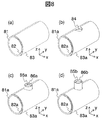
図2は、図1の磁場遮蔽装置の主要部の構成を示す斜視図である。図2(a)は、円筒型遮蔽体1の構成を示す図、図2(b)は、円筒型遮蔽体2の構成を示す図、図2(c)は、円筒型遮蔽体3の構成を示す図である。
FIG. 2 is a perspective view showing a configuration of a main part of the magnetic field shielding apparatus of FIG. 2A is a diagram showing a configuration of the
図2(a)の円筒型遮蔽体1は、第1の所定の角度範囲をもち中心軸に垂直な、両端部の2つの円弧部と、所定の小さい幅寸法及び所定の長さ寸法をもつ所定の小さい面積をもち中心軸に平行な2つの部位と、第1の所定の角度範囲をもつ円周部21と、円周部21に形成された開口部22とをもつ。z方向の磁場成分を検出する単数又は複数のSQUID磁束計を低温に保持するクライオスタットを開口部22の内部に配置し、クライオスタットの底面を、磁場遮蔽装置の内部に挿入する。
The
開口部22から磁場遮蔽装置の内部に侵入する環境磁場の影響による、磁場遮蔽装置の磁場遮蔽率の劣化防止のため、本発明の実施例では、開口部22を取り囲むように補助円筒体23を円筒型遮蔽体1に結合して配置した。補助円筒体23の効果を高めるために、補助円筒体23は多層構造にすることが望ましく、また、補助円筒体23のその軸方向の長さが長い方が望ましい。補助円筒体23は円筒型遮蔽体1と磁場的に結合していることが望ましく、一体形成されることが望ましい。
In the embodiment of the present invention, the auxiliary
しかし、一体形成は作業工程が困難であるので、補助円筒体23は、例えば、ネジ止めなどの方法で円筒型遮蔽体1に密着するように取り付けられる。ネジ止めなどの方法で補助円筒体23を円筒型遮蔽体1に密着させて取り付ける場合には、磁気的結合を確実にするために、図2(a)に示すように、補助円筒体23に鍔状板材24を溶接等により形成し、鍔状板材24を円筒型遮蔽体1に密着させて取り付けることが望ましい。
However, since the work process is difficult to form integrally, the
鍔状板材24は円周部21の外面と同じ曲率半径の円周面をなす。鍔状板材24を形成することにより、補助円筒体23と円筒型遮蔽体1との接触面積を広く確保できる。その結果、補助円筒体23と円筒型遮蔽体1との間から磁場遮蔽装置の内部に侵入する環境磁場が遮蔽され、磁場遮蔽率も向上する。
The bowl-shaped
図2(a)に示す円筒型遮蔽体1は、円筒型遮蔽体1の円周部21の内側直径は約102cm、外側直径は約114cmである。円筒型遮蔽体1の中心軸の方向の長さは、約200cmであり、第1の所定の角度範囲は約260度である。補助円筒体23には、鍔状板材24が形成されており、鍔状板材24は、開口部22を取り囲み円周部21に、密着して結合固定されており、補助円筒体23と円筒型遮蔽体1との磁場結合を向上させている。
In the
図2(b)の円筒型遮蔽体2は、第2の所定の角度範囲をもち中心軸に垂直な、両端部の2つの円弧部と、所定の小さい幅寸法及び所定の長さ寸法をもつ所定の小さい面積をもち、切欠き部25、26が形成される、中心軸に平行な2つの部位と、第2の所定の角度範囲をもつ円周部とをもつ。切欠き部26だけを形成しても良い。円筒型遮蔽体2は円筒型遮蔽体1の内側に配置される。切欠き部25、26は、円筒型遮蔽体2を、円筒型遮蔽体1の中心軸の周りに回転した時に、磁場遮蔽装置の内部に挿入されたクライオスタットと衝突しないように、クライオスタットのxy面での断面を包含する広さをもっている。円筒型遮蔽体2の円周部の内側直径は約94cm、外側直径は約100cmである。円筒型遮蔽体2の中心軸の方向の長さは、約200cmであり、第2の所定の角度範囲は約200度である。
The
図2(c)の円筒型遮蔽体3は、第3の所定の角度範囲をもち中心軸に垂直な、両端部の2つの円弧部と、所定の小さい幅寸法及び所定の長さ寸法をもつ所定の小さい面積をもち、切欠き部27、28が形成される、中心軸に平行な2つの部位と、第3の所定の角度範囲をもつ円周部とをもつ。円筒型遮蔽体3は円筒型遮蔽体1の外側に配置される。
The
切欠き部27、28は、円筒型遮蔽体3を、円筒型遮蔽体1の中心軸の周りに回転した時に、磁場遮蔽装置の内部に挿入されたクライオスタットと衝突しないように、クライオスタットのxy面での断面を包含する広さをもっている。円筒型遮蔽体3の円周部の内側直径は約116cm、外側直径は約122cmである。円筒型遮蔽体3の中心軸の方向の長さは、約200cmであり、第3の所定の角度範囲は約255度である。
The
図3は、図1の磁場遮蔽装置において、開口部9が最大となる状態、即ち、回転扉4が全開の状態を示す斜視図である。
FIG. 3 is a perspective view showing a state in which the
回転扉4のy軸の周りの一方向の回転により、磁場遮蔽装置の周方向の開口部9が最大の状態が形成される。回転扉4が全開の状態で、開口部9より検査対象を磁場遮蔽装置の内部にx方向から挿入できる。回転扉4に形成された切欠き部10は、円筒型遮蔽体2に形成された切欠き部26(図2(b))と円筒型遮蔽体3に形成された切欠き部28(図2(c))とから構成される。回転扉4に形成された切欠き部11は、円筒型遮蔽体3に形成された切欠き部27(図2(c))から構成される(図2(b)には、円筒型遮蔽体2に形成された切欠き部25を示しているが、切欠き部11を構成していない)。
By rotating the revolving
回転扉4を、円筒型遮蔽体1の中心軸の周りに回転した時に、回転扉4が、磁場遮蔽装置の内部に挿入されたクライオスタットと衝突しないように、切欠き部11は、クライオスタットのxy面での断面を包含する広さをもっている。回転扉4のy軸の周りの他方向に回転により、周方向に形成された開口部9は閉じられる。
In order to prevent the
図4は、図1の磁場遮蔽装置において、回転扉4が完全に閉じた状態を示す斜視図である。図4において、円筒型遮蔽体1、円筒型遮蔽体2、3により囲まれた内部空間では環境磁場は遮蔽されており、この内部空間におかれた検査対象から発する磁場が計測される。回転扉4を、円筒型遮蔽体1の中心軸の周りに回転した時に、回転扉4が、磁場遮蔽装置の内部に挿入されたクライオスタットと衝突しないように、切欠き部11は、クライオスタットのxy面での断面を包含する広さをもっている。
FIG. 4 is a perspective view showing a state in which the
回転扉4に形成される切欠き部10により、回転扉4を閉じた時に、円筒型遮蔽体1と回転扉4は重なり部をもっている。その結果、円筒型遮蔽体1と回転扉4との間に生じる隙間から磁場遮蔽装置の内部に侵入する環境磁場は遮蔽され、環境磁場雑音は低減され、磁場遮蔽装置の磁場遮蔽率を向上できる。
When the revolving
図5は、図1の磁場遮蔽装置の中心軸に垂直な面(補助円筒体23を通らない平面)での断面図である。図5(a)は、図3の磁場遮蔽装置のxz面に平行で、補助円筒体23を通らない平面での断面図であり、図5(b)は、図4の磁場遮蔽装置のxz面に平行で、補助円筒体23を通らない平面での断面図である。図5(a)は、回転扉4が最大限に開いた状態を示し、図5(b)は、図5(a)に示す矢印の方向への回転扉4の回転により、回転扉4が完全に閉じた状態を示す。クライオスタットが挿入される開口部22の位置は、図5(b)に示す点線のy軸の延長上に形成されている。
5 is a cross-sectional view taken along a plane perpendicular to the central axis of the magnetic field shielding apparatus of FIG. 1 (a plane not passing through the auxiliary cylinder 23). 5A is a cross-sectional view taken along a plane parallel to the xz plane of the magnetic field shielding apparatus of FIG. 3 and does not pass through the auxiliary
図5(a)、図5(b)に示すように、円筒型遮蔽体1、2、3は、高透磁率材料(パーマロイ板材)、高電気伝導率材料(アルミニウム板材)を、非磁性材料で骨組みとなる補強材に固定して構成される。図5(a)に示すように、円筒型遮蔽体1の円周面に沿った回転扉4のy軸の周りの一方向の回転により、周方向に開口部9が形成される。
As shown in FIGS. 5A and 5B, the
回転扉4が全開の状態では、y軸の周りに中心角が約100度の開口部9が周方向に形成される。この状態で、磁場遮蔽装置は、鉛直方向に約70cm、水平方向に約200cmの開口部9をもっており、この開口部9は、検査対象を仰臥位又は伏臥位で、磁場遮蔽装置の内部に挿入し、内部から搬出するのに十分な広さをもっている。
When the revolving
図5(b)に示すように、円筒型遮蔽体1の円周面に沿った回転扉4のy軸の周りの回転により、周方向に形成された開口部9がなくなる。回転扉4が完全に閉じた状態では、円筒型遮蔽体1と円筒型遮蔽体2の円周部は、円周方向の両端部で重なりをもち近接している。上方には、y軸の周りに中心角が約60度の重なり部が周方向に形成され、下方には同様に約40度の重なり部が周方向に形成されている。また、円筒型遮蔽体1と磁場遮蔽3の円周部も、円周方向の両端部で重なりをもち近接しており、上方には、y軸の周りに中心角が約60度の重なり部が周方向に形成され、下方には同様に約95度の重なり部が周方向に形成されている。
As shown in FIG. 5B, the
これらの重なり部の形成により、円筒型遮蔽体1と円筒型遮蔽体2との境界、円筒型遮蔽体1と円筒型遮蔽体3との境界に生じる空隙から磁場遮蔽装置の内部に侵入する環境磁場を遮蔽し、環境磁場を低減し、磁場遮蔽装置の磁場遮蔽率を向上できる。周方向の重なり部の長さは、空隙の幅に対して10倍以上もたせることが望ましい。円筒型遮蔽体1と円筒型遮蔽体2との間に生じる空隙の幅は約1cmであるのに対して、下方の約40度の重なり部では、周方向の重なり部の長さを約35cmとすることで磁場遮蔽率を高めている。同様に他の重なり部でも、周方向の重なり部の長さを空隙の幅の10倍以上確保して磁場遮蔽率を高めている。
Due to the formation of these overlapping portions, the environment that enters the inside of the magnetic field shielding device from the gap formed at the boundary between the
図1から図5に示す例では、クライオスタットが挿入される開口部22の位置は、z軸の正の領域の上方に形成されている。図1から図5に示す例では、円筒型遮蔽体2、3の、y軸の周方向の一方の端でy軸に平行な部位、及び、円筒型遮蔽体3のy軸の周方向の他方の端でy軸に平行な部位に切欠き部が形成されている。図2(b)には、切欠き部25を示しているが、円筒型遮蔽体2の、y軸の周方向の他方の端でy軸に平行な部位に切欠き部25は形成しなくてもよい。
In the example illustrated in FIGS. 1 to 5, the position of the
なお、図5(a)、図5(b)において、クライオスタットが挿入される開口部22の位置をそのままの位置として、円筒型遮蔽体1、2、3の部分をy軸の周方向に、約60度だけ左回転させた場合を考えると、図5(a)の左上部、左下部は下方へ下がった位置へ移動し、y軸の周方向の位置は下方へ下がる。このような場合には、図2(b)、図2(c)に示す切欠き部25、27を形成し、切欠き部26、28を形成せずに、回転扉4は補助円筒体23にぶつかることなく回転可能となる。即ち、回転扉4に形成された切欠き部10(即ち、26、28)を形成する必要はない。従って、開口部22の中心位置は、通常の場合、yz面に置かれるので、円筒型遮蔽体1を配置するy軸の周方向での位置によって、図2(b)、図2(c)に示す切欠き部25、26、27、28の形成が必要か否かと、図2(b)に示す円筒型遮蔽体1に形成する開口部22の位置とが決定できる。これは、後述する図22の磁場遮蔽装置でも同様である。
図5(c)は、図5(b)の点線部分の拡大図であり、円筒型遮蔽体1、2、3の構造の詳細を示す断面図である。
5 (a) and 5 (b), with the position of the
FIG. 5C is an enlarged view of the dotted line portion of FIG. 5B, and is a cross-sectional view showing details of the structure of the
円筒型遮蔽体1の外側に配置される円筒型遮蔽体3は、高透磁率材料(厚さ1mmのパーマロイの板材)3−1、3−2と、非磁性材料より形成される補強材(SUS製の30mm角の角パイプ)33−3とから構成される。補強材33−3は、高透磁率材料3−1、3−2を補強して保持している。
The
円筒型遮蔽体1の内側に配置される円筒型遮蔽体2は、高透磁率材料(厚さ1mmのパーマロイの板材)2−1、2−2と、高電気伝導率材料(厚さ0.5mmのアルミニウムの板材)32−2、非磁性材料より形成される補強材(SUS製の30mm角の角パイプ)33−2とから構成される。補強材33−2は、高透磁率材料2−1、2−2、高電気伝導率材料32−2を補強して保持している。
The
円筒型遮蔽体2、3との間に配置され、遮蔽体支持体6a、6bに固定される円筒型遮蔽体1は、高透磁率材料(厚さ1mmのパーマロイの板材)1−1、1−2と、高電気伝導率材料(厚さ0.5mmのアルミニウムの板材)32−1、非磁性材料より形成される補強材(SUS製の60mm角の角パイプ)33−1とから構成される。補強材33−1は、高透磁率材料1−1、1−2、高電気伝導率材料32−1を補強して保持している。
The
図23は、図1から図5の磁場遮蔽装置のサイズをまとめた図である。
図23において、サイズは約の値を示し、外側直径、内側直径、パーマロイ板の合計厚を示す遮蔽体厚、中心軸の方向の長さ単位はcm、角度の単位は度である。
FIG. 23 is a diagram summarizing the sizes of the magnetic field shielding devices of FIGS. 1 to 5.
In FIG. 23, the size indicates an approximate value, the outer diameter, the inner diameter, the shield thickness indicating the total thickness of the permalloy plate, the length unit in the direction of the central axis is cm, and the angle unit is degree.
また、回転扉4が完全に閉時の重なり角を示す、上部外側重なり角は、外側遮蔽体と中側遮蔽体の上部の外側での重なり角を示し、上部内側重なり角は、中側遮蔽体と内側遮蔽体の上部の内側での重なり角を示し、下部内側重なり角は、内側遮蔽体と中側遮蔽体の下部の内側での重なり角を示し、下部外側重なり角は、中側遮蔽体と外側遮蔽体の下部の外側での重なり角を示す。
Further, the upper outer overlapping angle indicates the overlapping angle when the revolving
図6は、図1の磁場遮蔽装置の磁場遮蔽率の評価のためのシミュレーション解析に用いた第1のモデルを示す斜視図である。第1のモデルは、図1から図5に示す円筒型遮蔽体を単純化したものである。 FIG. 6 is a perspective view showing a first model used for simulation analysis for evaluating the magnetic field shielding rate of the magnetic field shielding apparatus of FIG. The first model is a simplified version of the cylindrical shield shown in FIGS.
図6(a)は、直径100cm、長さ200cm、厚さ2mmの比透磁率60000の高透磁率材料からなる円筒型の円筒型遮蔽体61のモデルを示す斜視図である。
FIG. 6A is a perspective view showing a model of a cylindrical
図6(b)は、図6(a)の円筒型遮蔽体61の円筒面のz軸と交叉する位置に中心をもつ直径40cmの円形の開口部63を形成した円筒型遮蔽体62のモデルを示す斜視図である。
FIG. 6B shows a model of the
図6(c)は、図6(b)の円筒型遮蔽体62の開口部63の外周に沿って、比透磁率60000の高透磁率材料からなる内側直径40cm、z軸方向の長さ約50cm、厚さ2mmの補助円筒体64を結合して形成した円筒型遮蔽体のモデルを示す斜視図である。
FIG. 6C shows an inner diameter of 40 cm made of a high permeability material having a relative permeability of 60000 along the outer periphery of the
なお、図6(a)、図6(b)、図6(c)では、直交座標系(x、y、z)の、原点(0、0、0)を磁場遮蔽装置61、62の中心Oとし、鉛直方向をz軸とし、磁場遮蔽装置の中心軸をy軸とし、xy面を、単数又は複数のSQUID磁束計による計測面に平行な面とする。SQUID磁束計は磁場のz軸方向の成分を検出する。
6A, 6B, and 6C, the origin (0, 0, 0) of the orthogonal coordinate system (x, y, z) is the center of the magnetic
図24は、図6に示す第1のモデルのサイズをまとめた図である。
図24において、サイズは約の値を示し、単位は、図23に示す、図1から図5の磁場遮蔽装置に関するサイズの単位と同じである。
FIG. 24 is a table summarizing the sizes of the first model shown in FIG.
In FIG. 24, the size indicates an approximate value, and the unit is the same as the unit of size related to the magnetic shielding apparatus shown in FIGS. 1 to 5 shown in FIG.
図6(a)、(b)、(c)に示す第1のモデルに対して、z方向に一様な磁場を印加した場合における、磁場遮蔽装置の内部の磁場分布を3次元有限要素法シミュレーションにより求めた。 A three-dimensional finite element method is used to calculate the magnetic field distribution inside the magnetic shielding apparatus when a uniform magnetic field is applied in the z direction to the first model shown in FIGS. 6 (a), (b), and (c). Obtained by simulation.
図7は、第1のモデルに対するシミュレーションにより得られた結果(磁場遮蔽率の分布)を示すグラフあり、磁場遮蔽装置の内部の磁場分布を、y軸上での磁場遮蔽率の分布として示すグラフである。 FIG. 7 is a graph showing the result (magnetic field shielding rate distribution) obtained by the simulation for the first model, and showing the magnetic field distribution inside the magnetic shielding device as the magnetic field shielding rate distribution on the y-axis. It is.
一様な環境磁場(z軸方向の成分のみをもつ)を(0、0、B0)とし、磁場遮蔽装置の内部の座標(x、y、z)での磁場を{Bx(x、y、z)、By(x、y、z)、Bz(x、y、z)}、磁場の大きさを(数1)とした時、座標(x、y、z)の磁場遮蔽率S(x、y、z)(dB)は、(数2)で定義される(logは常用対数である)。図7は、磁場遮蔽率S(x、y、z)の位置yに対する変化を示している。
|B(x、y、z)|
=√{Bx(x、y、z)×Bx(x、y、z)
+By(x、y、z)×By(x、y、z)
+Bz(x、y、z)×Bz(x、y、z)} …(数1)
S(x、y、z)=20log{|B0|/|B(x、y、z)|}
…(数2)
図7の横軸yは、図6(a)、図6(b)、図6(c)の第1のモデルにおけるy座標(単位:m)を示す。y=0は磁場遮蔽装置の中心(原点)位置を示し、y=1mは磁場遮蔽装置の開口端の位置を示す。図7の縦軸は、横軸y(図6の座標(0、y、0)に対応する)での磁場遮蔽率(dB)を示す。
A uniform environmental magnetic field (having only a component in the z-axis direction) is set to (0, 0, B0), and the magnetic field at coordinates (x, y, z) inside the magnetic field shielding device is represented by {Bx (x, y, z), By (x, y, z), Bz (x, y, z)} and the magnitude of the magnetic field as (Equation 1), the magnetic field shielding rate S (x) at the coordinates (x, y, z) , Y, z) (dB) is defined by (Equation 2) (log is a common logarithm). FIG. 7 shows changes in the magnetic field shielding rate S (x, y, z) with respect to the position y.
| B (x, y, z) |
= √ {Bx (x, y, z) x Bx (x, y, z)
+ By (x, y, z) × By (x, y, z)
+ Bz (x, y, z) × Bz (x, y, z)} (Expression 1)
S (x, y, z) = 20 log {| B0 | / | B (x, y, z) |}
... (Equation 2)
The horizontal axis y in FIG. 7 indicates the y coordinate (unit: m) in the first model in FIGS. 6 (a), 6 (b), and 6 (c). y = 0 indicates the center (origin) position of the magnetic shielding device, and y = 1 m indicates the position of the open end of the magnetic shielding device. The vertical axis in FIG. 7 represents the magnetic field shielding rate (dB) on the horizontal axis y (corresponding to the coordinates (0, y, 0) in FIG. 6).
図7のグラフ(a)は、図6(a)の第1のモデルに対する結果を示す。磁場遮蔽率は、磁場遮蔽装置の中心位置y=0で最大(約40dB)であり、y=0からy=1mに近づくに従って減少し、y=1mでは約11dBである。 Graph (a) in FIG. 7 shows the results for the first model in FIG. 6 (a). The magnetic field shielding rate is maximum (about 40 dB) at the center position y = 0 of the magnetic field shielding device, decreases as y = 1 m approaches y = 0, and is about 11 dB at y = 1 m.
図7のグラフ(b)は、図6(b)に示す第1のモデルに対する結果を示す。磁場遮蔽率は、y=0で約29dBであり、開口部63の影響により、図6(a)の第1のモデルに比較して、y=0で約11dBも減少している。磁場遮蔽率は、y=0からy=1mに近づくに従って、最初は少しずつ増加し、y≒0.4mで最大(約33dB)となり、それから減少し始め、y≧0.6mでは、図6(a)の第1のモデルとほぼ同様の値となる。 Graph (b) in FIG. 7 shows the results for the first model shown in FIG. 6 (b). The magnetic field shielding rate is about 29 dB when y = 0, and is reduced by about 11 dB at y = 0 as compared to the first model of FIG. The magnetic field shielding rate gradually increases as y = 0 to y = 1 m, and gradually increases to a maximum (about 33 dB) when y≈0.4 m, and then starts to decrease. When y ≧ 0.6 m, FIG. The value is almost the same as that of the first model of (a).
図7のグラフ(c)は、図6(c)の第1のモデルに対する結果を示す。磁場遮蔽率は、y=0で最大(約38dB)であり、補助円筒体64の効果により、図6(b)の第1のモデルに比較して、y=0で約9dBも磁場遮蔽率が増加している。また、図6(a)の第1のモデルに比較しても、y=0で約2dB減少しているだけである。これは補助円筒体64が、開口部63による磁場遮蔽率の劣化の防止に非常に効果的に作用していることを示している。図6(c)の第1のモデルでは、−0.4m≦y≦0.4mの範囲で、磁場遮蔽率は35dB以上である。
Graph (c) in FIG. 7 shows the results for the first model in FIG. 6 (c). The magnetic field shielding rate is maximum (about 38 dB) when y = 0, and due to the effect of the auxiliary
図8は、図1の磁場遮蔽装置の磁場遮蔽率の評価のためのシミュレーション解析に用いた第2のモデルを示す斜視図である。
図8(a)は、比透磁率60000の高透磁率材料からなり、y軸方向の長さ200cm、厚さ1mmをもつ2つの円周部よりなる円筒型遮蔽体81、82、83より構成される第2のモデルの斜視図である。円筒型遮蔽体81、82、83は、所定の角度範囲をもち中心軸に垂直な、両端部の2つの円弧部と、所定の小さい幅寸法及び所定の長さ寸法をもつ所定の小さい面積をもち中心軸に平行な2つの部位と、所定の角度範囲をもつ円周部とをもつ。
FIG. 8 is a perspective view showing a second model used for the simulation analysis for evaluating the magnetic field shielding rate of the magnetic field shielding apparatus of FIG.
FIG. 8 (a) is made of a high-permeability material having a relative magnetic permeability of 60000, and is composed of
円筒型遮蔽体82、83は同じ角度範囲をもち、円筒型遮蔽体81は、円筒型遮蔽体82、83と異なる所定の角度範囲をもつ。円筒型遮蔽体81の内側に円筒型遮蔽体82が配置され、円筒型遮蔽体81の外側に円筒型遮蔽体83が配置される。
The cylindrical shields 82 and 83 have the same angle range, and the
円筒型遮蔽体81は、円筒型遮蔽体82、83と重なり部をもつ。円筒型遮蔽体81の円周部の内側直径は102cm、外側直径は114cmであり、所定の角度範囲は260度である。
The
円筒型遮蔽体82の円周部の内側直径は94cm、外側直径は100cmであり、所定の角度範囲は200度である。
円筒型遮蔽体83の円周部の内側直径は116cm、外側直径は122cmであり、所定の角度範囲は約200度である。
The inner diameter of the circumferential portion of the
The inner diameter of the circumference of the
図8(a)に示すように、円筒型遮蔽体82、83は、円筒型遮蔽体81と、z軸の正の領域で60度の重なりをもち、z軸の負の領域で40度の重なりをもち配置されている。図8(a)の第2のモデルは、図1から図5に示す磁場遮蔽装置の構成から、開口部22、切欠き部10、11、補助円筒体23、鍔状板材24を取り除いた構成に類似する。
As shown in FIG. 8A, the
図8(b)は、図8(a)の円筒型遮蔽体の円筒面のz軸と交叉する位置に中心をもつ直径40cmの円形の開口部84を形成した第2のモデルを示す斜視図である。
図8(b)の第2のモデルは、円筒型遮蔽体81a、82a、83aより構成される。円筒型遮蔽体82a、83aは、図8(a)の円筒型遮蔽体82、83の中心軸に平行な2つの部位の一方に切欠き部をもつ点を除いて、円筒型遮蔽体82、83と材質、寸法は同じである。円筒型遮蔽体81aは、図8(a)の円筒型遮蔽体81の円周部にz軸を中心軸とする直径約40cmの開口部を形成する点を除いて、円筒型遮蔽体81と材質、寸法は同じである。図8(b)の第2のモデルは、図1から図5で説明した磁場遮蔽装置の構成から補助円筒体23、鍔状板材24を取り除いた構成に類似する。
FIG. 8B is a perspective view showing a second model in which a
The second model in FIG. 8B is composed of
図8(c)は、図8(b)の円筒型遮蔽体の変形例であり、開口部に補助円筒体85a、86aを付加した構成をもつ第2のモデルの斜視図を示す。
補助円筒体85a、86aは、z軸方向の長さ約17cm、厚さ1mm、比透磁率60000の高透磁率材料からなる。円筒型遮蔽体81aは、図8(a)の円筒型遮蔽体81の円周部にz軸を中心軸とする直径約40cmの開口部を形成する点を除いて、円筒型遮蔽体81と材質、寸法は同じである。直径約40cmの補助円筒体85aは、円筒型遮蔽体81aの開口部に磁気的に結合され、直径約52cmの補助円筒体86aは、円筒型遮蔽体81aの円周部の外面に磁気的に結合される。図8(c)の第2のモデルは、図1から図5で説明した磁場遮蔽装置と類似する構成であるが、開口部を囲むように磁気結合された2つの補助円筒体をもつ点で異なる。
FIG. 8C is a modification of the cylindrical shield of FIG. 8B, and shows a perspective view of a second model having a configuration in which auxiliary
The
図8(d)は、図8(c)の円筒型遮蔽体の変形例であり、図8(c)の補助円筒体85a、86aのz軸方向の長さ(約17cm)を約14cm長くして、約31cmと変更した補助円筒体85b、86bを使用する第2のモデルの斜視図を示す。
図8(a)、(b)、(c)、(d)の第2のモデルに対して、z方向に一様な磁場を印加した場合における、磁場遮蔽装置の内部の磁場分布を3次元有限要素法シミュレーションにより求めた。
FIG. 8D is a modification of the cylindrical shield of FIG. 8C, and the length (about 17 cm) in the z-axis direction of the auxiliary
The three-dimensional magnetic field distribution inside the magnetic shielding apparatus when a uniform magnetic field is applied in the z direction to the second model of FIGS. 8A, 8B, 8C, and 8D. It was obtained by finite element method simulation.
図9は、第2のモデルに対するシミュレーションにより得られた結果(磁場遮蔽率の分布)を示すグラフであり、磁場遮蔽装置の内部の磁場分布を、y軸上での磁場遮蔽率の分布として示すグラフである。
図25は、図8(a)に示す第2のモデルのサイズをまとめた図である。
図26は、図8(b)に示す第2のモデルのサイズをまとめた図である。
図27は、図8(c)に示す第2のモデルのサイズをまとめた図である。
図28は、図8(d)に示す第2のモデルのサイズをまとめた図である。
FIG. 9 is a graph showing the results (magnetic field shielding rate distribution) obtained by the simulation for the second model, and shows the magnetic field distribution inside the magnetic field shielding device as the magnetic field shielding rate distribution on the y-axis. It is a graph.
FIG. 25 is a table summarizing the sizes of the second model shown in FIG.
FIG. 26 is a table summarizing the sizes of the second model shown in FIG.
FIG. 27 is a table summarizing the sizes of the second model shown in FIG.
FIG. 28 is a table summarizing the sizes of the second model shown in FIG.
図25、図26、図27、図28において、サイズは約の値を示し、単位は、図23及び図24に示す、図1から図5、及び、図6に示す磁場遮蔽装置に関するサイズの単位と同じである。 In FIG. 25, FIG. 26, FIG. 27, and FIG. 28, the size indicates an approximate value, and the unit is the size of the magnetic field shielding device shown in FIG. 1 to FIG. 5 and FIG. Same as unit.
図9の、横軸は第2のモデルにおけるy座標を、縦軸は磁場遮蔽率を示す。図9の横軸、縦軸の単位は、図7と同じである。
図9のグラフ(a)は、図8(a)の第2のモデルに対する結果を示す。磁場遮蔽率は、y=0で最大(約50dB)であり、y=0からy=1mに近づくに従って減少し、y=1mでは約13dBである。
図9のグラフ(b)は、図8(b)の第2のモデルに対する結果を示す。磁場遮蔽率は、y=0で約38dBである。開口部84の影響により、y=0で図9(a)の第2のモデルに比較して、約12dBも磁場遮蔽率が減少している。y=0からy=1mに近づくに従って、最初は少しずつ増加し、y≒0.35mで最大(約40dB)となり、それから減少し始め、y≧0.6m、では図9(a)の第2のモデルとほぼ同様の値となる。
In FIG. 9, the horizontal axis represents the y coordinate in the second model, and the vertical axis represents the magnetic field shielding rate. The units of the horizontal and vertical axes in FIG. 9 are the same as those in FIG.
The graph (a) in FIG. 9 shows the results for the second model in FIG. 8 (a). The magnetic field shielding rate is maximum (about 50 dB) at y = 0, decreases as y = 0 approaches y = 1 m, and is about 13 dB at y = 1 m.
Graph (b) in FIG. 9 shows the results for the second model in FIG. 8 (b). The magnetic field shielding rate is about 38 dB when y = 0. Due to the influence of the
図9のグラフ(c)は、図8(c)の第2のモデルに対する結果を示す。磁場遮蔽率は、y=0で最大(約46dB)である。補助円筒体85a、86aの効果により、図9(b)に比較してy=0で約8dBも磁場遮蔽率が増加している。これは補助円筒体85a、86aが、開口部84による磁場遮蔽率の劣化防止に非常に効果的に寄与していることを示している。
Graph (c) in FIG. 9 shows the results for the second model in FIG. 8 (c). The magnetic field shielding rate is maximum (about 46 dB) when y = 0. Due to the effects of the
図9のグラフ(d)は、図8(d)の第2のモデルに対する結果を示す。磁場遮蔽率は、y=0で最大(約49dB)である。補助円筒体85b、86bの効果により、図9(b)に比較して中心位置で約11dBも磁場遮蔽率が増加している。図8(d)の第2のモデルでは、開口部84による磁場遮蔽率の劣化防止のために、図8(c)の補助円筒体85a、86aの軸方向の長さを長くしている。
The graph (d) in FIG. 9 shows the results for the second model in FIG. 8 (d). The magnetic field shielding rate is maximum (about 49 dB) when y = 0. Due to the effect of the auxiliary
図9のグラフ(c)と(d)の比較から、補助円筒体85b、86bの長さを長くした効果により、磁場遮蔽率がy=0で3dB増加していることが分かる。また、図9のグラフ(d)と(a)の比較から、グラフ(d)では、磁場遮蔽率はy=0で約1dB減少しているだけであることが分かる。
From the comparison between graphs (c) and (d) in FIG. 9, it can be seen that the magnetic field shielding rate increases by 3 dB at y = 0 due to the effect of increasing the lengths of the
以上の結果から、補助円筒体85b、86bが、開口部84による磁場遮蔽率の劣化防止に非常に効果的に寄与していることを示している。また、図9のグラフ(c)と(d)の結果から明らかなように、補助円筒体は、軸方向の長さが長い方がより磁場遮蔽効果が大きいことが分かる。図8(c)の第2モデルでは、−0.29m≦y≦0.29mの範囲で、図8(d)の第2モデルでは、−0.32m≦y≦0.32mの範囲で、それぞれ、磁場遮蔽率を45dB以上である。補助円筒体のその軸方向の長さは、開口部の内径以上の長さをもつことが望ましい。
From the above results, it is shown that the auxiliary
また、図7と図9の比較から明らかなように、磁場遮蔽装置に中心軸に直交する方向でのパーマロイ板の合計厚さTが大である程、磁場遮蔽率が向上することは明らかである。従って、図6(c)の第1のモデルにおいて合計厚さTを大とすれば、図7と図9の比較から、概略、−0.4m≦y≦0.4mの範囲で、図8(c)、図8(d)に近い磁場遮蔽率の特性が得られるものと予想され、図6(c)のような単純な構造でも、装置の中心軸の方向から、検査対象を装置の内部に搬入する必要があるが、小型の磁場遮蔽装置が可能と予想される。
図10は、本発明の実施例の生体磁場計測装置の主要部の構成を示す斜視図であり、磁場遮蔽装置の回転扉4が全開の状態を示し(図3を参照)、天板121を、磁場遮蔽装置の外部に引き出した状態を示している。
Further, as is clear from the comparison between FIG. 7 and FIG. 9, it is clear that the magnetic field shielding ratio improves as the total thickness T of the permalloy plate in the direction perpendicular to the central axis of the magnetic field shielding device increases. is there. Therefore, if the total thickness T is increased in the first model of FIG. 6C, the comparison between FIG. 7 and FIG. 9 shows that in the range of −0.4 m ≦ y ≦ 0.4 m, FIG. (C) It is expected that the characteristics of the magnetic field shielding rate close to those in FIG. 8 (d) can be obtained. Even with a simple structure as shown in FIG. 6 (c), the inspection object is moved from the direction of the central axis of the apparatus. Although it is necessary to carry in the inside, it is expected that a small magnetic shielding apparatus is possible.
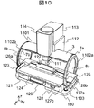
FIG. 10 is a perspective view showing the configuration of the main part of the biomagnetic field measurement apparatus according to the embodiment of the present invention, in which the
以下で説明する図10から図17に関する磁場遮蔽装置のサイズは、図8(c)に示す第2のモデルのサイズと同じである。
図11は、図10の生体磁場計測装置のクライオスタット部、ガントリ部の構成を示す斜視図である。
図12は、図10の生体磁場計測装置のベッド部の構成を示す斜視図である。
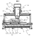
図13は、図10に示す生体磁場計測装置のyz平面での断面図である。
図14は、図10に示す生体磁場計測装置のzx平面での断面図である。
The size of the magnetic shielding apparatus described below with reference to FIGS. 10 to 17 is the same as the size of the second model shown in FIG. 8C.
FIG. 11 is a perspective view showing a configuration of a cryostat unit and a gantry unit of the biomagnetic field measurement apparatus of FIG.
FIG. 12 is a perspective view showing the configuration of the bed portion of the biomagnetic field measurement apparatus of FIG.
13 is a cross-sectional view of the biomagnetic field measurement apparatus shown in FIG. 10 on the yz plane.
14 is a cross-sectional view of the biomagnetic field measurement apparatus shown in FIG. 10 on the zx plane.
図13、図14は、2層の補助円筒体23−1、23−2、磁場遮蔽装置の円筒型遮蔽体1、2、3、11、クライオスタット111、複数のSQUID磁束計131、ガントリ112、天板121、天板121をx、y、z方向で移動させるための要素126a、126b、125、127a、127b、127c等の、相互の位置関係、構造を示している。
13 and 14 show two-layer auxiliary cylinders 23-1 and 23-2,
図10の生体磁場計測装置は、大別して、図10に図示する、磁場遮蔽部、クライオスタット部、ガントリ部、ベッド部、及び、図10に図示しない、SQUID駆動回路、演算処理装置(コンピュータ)、表示装置、入力装置から構成される。なお、図10に図示しない構成要素については、後述の図17で図示され、詳細に説明される。 The biomagnetic field measurement apparatus in FIG. 10 is roughly divided into a magnetic field shielding unit, a cryostat unit, a gantry unit, a bed unit, and a SQUID driving circuit, an arithmetic processing unit (computer), which are not shown in FIG. It consists of a display device and an input device. Note that components not shown in FIG. 10 are shown in FIG. 17 described later and will be described in detail.
磁場遮蔽部は、図1から図5の磁場遮蔽装置と同様の構成をもつ磁場遮蔽装置1101からなる。回転扉4の開閉に使用する回転ハンドル1102a、1102bは、図1の回転扉4と結合しており、回転ハンドル1102a又は1102bの手動回転により、回転扉4の開閉ができ、開口部9の広さが変化する。回転扉4のロックのオンオフが、回転扉4のロック機構1103を足で踏む操作により容易にできる。図10では、ロック機構1103は、y軸の正の領域に配置されるが、y軸の負の領域に配置しても良い。
The magnetic shielding unit includes a
また、天板受入れ台127cに配置される操作レバー128により、空気圧又は油圧ポンプが制御され、天板121を保持する天板保持台125のz方向の位置調整が容易にできる。天板受入れ台127cに配置される図示しない回転操作ボタンにより、空気圧又は油圧ポンプ等を用いて回転駆動させ、回転扉4の開閉制御を容易にできる。さらに、天板受入れ台127cに配置された天板移動部の図示しない移動操作ボタンにより、天板121のxy平面に平行な面内で移動は制御できる。
Further, the pneumatic lever or the hydraulic pump is controlled by the
従って、磁場遮蔽装置の前面位置で、検査技師は、検査対象を観察しながら、天板受入れ台127cに配置される、回転操作ボタン、操作レバー、移動操作ボタンを、必要に応じて選択使用して、天板121の位置調整制御、回転扉4の開閉制御をできるので、検査対象に不安感を与えない。もちろん、磁場遮蔽装置の前面位置で、検査技師は、検査対象を観察しながら、手動によっても、天板121の位置調整、回転扉4の開閉をできる。
クライオスタット部は、単数又は複数のSQUID磁束計を低温に保持して下部の内部に収納するクライオスタット111を保持する。クライオスタット111は非磁性材料(FRP樹脂等)で構成することが望ましい。
Therefore, at the front position of the magnetic shielding apparatus, the inspection engineer selects and uses the rotation operation button, the operation lever, and the movement operation button, which are arranged on the top table receiving table 127c, as necessary while observing the inspection object. In addition, since the position adjustment control of the
The cryostat unit holds a
ガントリ部は、クライオスタット部のクライオスタット111を保持するガントリ112を含む。ガントリ部は、非磁性材料(アルミニウム、SUS等)から構成されることが望ましい。ガントリ112は、ガントリ支持台112a、112bで固定され、ガントリ支持台112a、112bは、ベッド部支持板130に固定されている。ガントリ112の上方には、クライオスタット111の外周面の上方に形成されている鍔部116を受け入れる円弧部が形成されている。
The gantry unit includes a
ガントリ112及びクライオスタット111の上方は、上方カバー113により保護される。また、ガントリ112及びクライオスタット111の前方は、前方カバー114により保護される。上方カバー113、前方カバー114は、高透磁率材料(パーマロイ等)、高電気伝導率材料(アルミニウム等)で構成することが望ましい。上方カバー113、前方カバー114は、漏洩磁場を遮蔽するだけでなく、SQUID磁束計の性能を劣化させる高周波の電磁波を遮蔽する働きをもつ。
The upper part of the
ベッド部は、検査対象を搭載する天板121、天板121を保持する天板保持台125、天板121を保持してxy平面に平行な面内で移動させる天板移動部と、天板保持台125を保持してz軸方向に移動させる天板保持台移動部127a、127b(図10の斜視図では見えず、図12のベッド部の構成を示す斜視図に示される)、天板受入れ台127cとを含む。ベッド部は、非磁性材料(木材、アルミニウム、SUS等)から構成されることが望ましい。
The bed unit includes a
天板121には、検査対象の両手にそれぞれ対応する側の、手前側の柵124、後側の柵122、及び、両脚に対応する側の柵123が配置されている。柵122、124は、検査対象が天板121の上からx方向にはみ出さないように設けられる。柵123は、検査対象の足が天板121の上からy方向にはみ出さないように設けられる。
On the
検査対象から発する磁場を計測する時に、検査対象を搭載する天板121は、磁場遮蔽装置1101の内部に配置されるが、図10では、検査対象を天板121に搭載するために、天板121が、天板保持台125の上で、磁場遮蔽装置1101の外部に移動されており、手前側の柵124が倒されている状態を示している。
When measuring the magnetic field emitted from the inspection target, the
天板保持台125は、y方向の両端の開口部8a、8bを貫通して磁場遮蔽装置1101の内部に配置され、磁場遮蔽装置1101の外部に配置された天板保持台移動部127a、127bに保持されている。
天板移動部は、天板移動板126a、126bと、天板121を保持してxy平面に平行な面内で移動させるために使用される構成要素とを含む。この構成要素は、非磁性材料から構成される、凸状レールの凸部と凹状レールの凹部の組合わせ、滑車、ボールベアリング等を含む。天板121のxy平面に平行な面内で移動は、天板受入れ台127cに配置された天板移動部の移動操作ボタンにより自動制御、又は、天板121の手動による移動操作により行われる。
The top
The top plate moving unit includes top
天板121の裏面に配置された天板移動板126aに保持され、天板121は、天板移動板126aに対してxy平面に平行な面内のx方向に移動可能である。天板121の裏面にx方向に配置された凸状レールの凸部が、天板移動板126aのx方向に配置された凹状レールの凹部に挿入される。
The
天板移動板126aは、天板移動板126bに対してxy平面に平行な面内のy方向に移動可能である。天板移動板126aは、凸状レールの凸部と凹状レールの凹部の組合わせ、滑車、ボールベアリング等を介して、天板移動板126bに保持される。
天板移動板126aは、天板保持台125に対してxy平面に平行な面内のx方向に移動可能である。天板移動板126bのy方向の両端部は、天板保持台125のy方向のxy面に形成される凹部のy方向の両端部のxz面に平行な内壁面に形成される凹部レールの凹部に挿入される。
The top
The top
天板121のz方向の移動は、手前に配置される天板受入れ台127cに配置される操作レバー128により制御される。天板保持台移動部127a、127bは、ベッド部支持板130に配置される凹部に収納保持される。なお、ベッド部支持板130に配置される凹部は、図10、図12、後述の図15から図18に図示されないが、図13、図14、後述の図20に図示される。天板保持台移動部127a、127bは、非磁性材料(アルミニウム、SUS等)から構成される、空気圧又は油圧ポンプを含む。空気圧又は油圧ポンプは、操作レバー128により制御される。
The movement of the
磁場遮蔽装置、ベッド部、ガントリ部は、相互に荷重が付加されないように、相互に独立して配置される。磁場遮蔽装置の荷重は、遮蔽体支持体6a、6bで支えられ、ベッド部の荷重は、天板保持台移動部127a、127bで支えられ、ガントリ部の荷重は、ガントリ支持台112a、112bで支えられる。
The magnetic shielding device, the bed unit, and the gantry unit are arranged independently of each other so that no load is applied to each other. The load of the magnetic field shielding device is supported by the
ベッド部は、ベッド部支持板130に保持される。また、天板保持台移動部127a、127b、天板受入れ台127c、ガントリ支持台112a、112bと結合されたガントリ112は、ベッド部支持板130に保持される。また、y軸の正又は負の領域に配置されるロック機構1103は、ベッド部支持板130の手前側に保持される。さらに、ベッド部支持板130の手前側に、クライオスタット111を任意の高さに保持して運送する運送台車(図示せず)の下部(図示せず)がベッド部の下方に挿入可能な台車挿入口129が形成されている。
The bed part is held by the bed
なお、天板121のx、y、z方向での移動機構、及び、回転扉4の回転機構に関する詳細な説明は後述する。
次に、クライオスタット111をガントリ112に装着する手順を、磁場遮蔽装置の組立の手順の一部、装置の構造の一部の説明を含めて、詳細に説明する。
In addition, the detailed description regarding the moving mechanism in the x, y, z direction of the
Next, a procedure for mounting the
先ず、図1から図5に示す磁場遮蔽装置のように、鍔状板材24が形成された1層の補助円筒体23が、開口部22を取り囲むように円筒型遮蔽体1に磁気的に結合させて配置される場合、又は、図10から図17に示すに示す磁場遮蔽装置のように、鍔状板材が鍔状板材24と同じように形成された、多層の補助円筒体、例えば、2層の補助円筒体23−1、23−2の2層が、開口部22を取り囲むように円筒型遮蔽体1に磁気的に結合させて配置される場合について、説明する(以下、「装着手順−1」と言う)。
First, as in the magnetic field shielding apparatus shown in FIGS. 1 to 5, the one-layer
運送台車は、鍔部116の前方部分を受け入れて、鍔部116の上方のクライオスタット111の円周部分を挟み込んで固定保持可能なクライオスタット保持部をもっている。運送台車のクライオスタット保持部のz軸方向の高さを調整して、クライオスタット作業台(鍔部116を受け入れる形状をもちクライオスタットが固定、保持されている)から、クライオスタット111を受け入れて、運送台車に固定する。所望の高さでクライオスタット111を保持した運送台車は、x軸に沿って移動され、運送台車の下部が台車挿入口129に挿入される。
The carriage has a cryostat holding portion that receives a front portion of the
運送台車を、必要に応じて、x軸、y軸、z軸方向に沿って移動させることにより、円筒型遮蔽体1に磁気結合された1層又は多層(例えば、2層)の補助円筒体の内部に上方から挿入して、鍔部116を、ガントリ112の上方の円弧部に挿入して固定する。1層又は多層の補助円筒体の上面は、ガントリ112の上方の円弧部の下方に配置されている(図13、図14を参照)。
A single-layer or multi-layer (for example, two-layer) auxiliary cylinder that is magnetically coupled to the
円筒型遮蔽体1に結合されている1層又は多層の補助円筒体を取り外すことが困難な場合、又は、取り外すことを想定しない設計で製作されている場合には、クライオスタット111の装着は、以上の手順による(取外しについては、後述する)。この場合、以下に説明する、装着手順−2(取外しについては、後述する)に比較して、余計な高さが、円筒型遮蔽体が設置される場所に必要となる。
When it is difficult to remove the single-layer or multi-layer auxiliary cylinder coupled to the
装着手順−2(取外しについては、後述する)は、円筒型遮蔽体1に結合されている1層又は多層の補助円筒体を取り外すことを、想定して設計で製作されている場合に適用できる。以下では、補助円筒体を2分割して製作して、円筒型遮蔽体1に結合したり取外しできるようにする一例を示す。この例は、水平方向の動作が主であり、円筒型遮蔽体が設置される場所に高さの厳しい条件はない。以下で示す例の他、各種の方法が可能である。
The mounting procedure-2 (the removal will be described later) can be applied to a case where the one-layer or multi-layer auxiliary cylinder coupled to the
次に、図1から図5、及び、図13、図14の磁場遮蔽装置の円筒型遮蔽体1に形成する開口部22を異なる方法で形成する場合について説明する(以下、「装着手順−2」と言う)。装着手順−1と異なり、装着手順−2では、円筒型遮蔽体1に形成する開口部22を形成する代わりに、図2(a)で説明した、円筒型遮蔽体1の中心軸に平行な2つの部位のうち、開口部22に近い方の部位に、開口部22の直径の幅をもち、開口部22に接し開口部22に近い方の部位に直交する直線部をもつ、開口部22に繋がるUの字型の切欠き部を形成する。
Next, a case where the
円筒型遮蔽体1のUの字型の切欠き部のうち開口部22を除く部分を塞ぐ、第1、第2補助板材は、予め準備されている。第1、第2補助板材はそれぞれ、円筒型遮蔽体1の円周部の内面、外面と同じ曲率半径の円周面をなす。
The 1st, 2nd auxiliary | assistant board | plate material which blocks the part except the
鍔状板材24が形成された1層の補助円筒体23(図1から図5を参照)を使用する場合(以下、「装着手順−2a」と言う)には、例えば、補助円筒体23の中心軸を通り、中心軸に平行な面で、鍔状板材24が形成された補助円筒体23を鍔状板材24と共に分割した形状をもつ、第1、第2分割体により、鍔状板材24が形成された補助円筒体23を構成する。第1分割体の鍔状板材は、図2(a)で説明したように、円筒型遮蔽体1の円周部の外面に、磁気的に予め結合されている。
When using the one-layer auxiliary cylindrical body 23 (see FIGS. 1 to 5) on which the bowl-shaped
装着手順−1と同様にして、所望の高さでクライオスタット111を保持した運送台車を、必要に応じて、x軸、y軸、z軸方向に沿って移動させることにより、円筒型遮蔽体1に磁気結合された第1分割体の内部に前方又は上方から挿入して、クライオスタット111の鍔部116を、ガントリ112の上方の円弧部に挿入して固定する。
In the same manner as in the mounting procedure-1, the
次に、図2(a)で説明したように、第1補助板材を、円筒型遮蔽体1の円周部の内面で、Uの字型の切欠き部の直線部に、磁気的に結合し、第2補助板材を、円筒型遮蔽体1の円周部の外面で、Uの字型の切欠き部の直線部に、磁気的に結合する。第2分割体の鍔状板材を、第2補助板材及び/又は円筒型遮蔽体1の円周部の外面に磁気的に結合すると共に、第2分割体の鍔状板材と第1分割体の鍔状板材とを磁気的に結合し、第2分割体の補助円筒体と第1分割体の補助円筒体とを磁気的に結合する。
Next, as explained in FIG. 2A, the first auxiliary plate member is magnetically coupled to the inner surface of the circumferential portion of the
多層の補助円筒体、例えば、2層の補助円筒体23−1、23−2(図13、図14を参照)を使用する場合(以下、「装着手順−2b」と言う)には、例えば、補助円筒体23−1、23−2のそれぞれの中心軸を通り、それぞれの中心軸に平行な面で、鍔状板材が形成された補助円筒体23−1、23−2のそれぞれを鍔状板材と共に分割した形状をもつ、補助円筒体23−1の第1、第2分割体、及び、補助円筒体23−2の第1、第2分割体により、鍔状板材が形成された補助円筒体23−1、23−2を構成する。 When using a multi-layer auxiliary cylinder, for example, two-layer auxiliary cylinders 23-1, 23-2 (see FIGS. 13 and 14) (hereinafter referred to as “mounting procedure-2b”), for example, Each of the auxiliary cylinders 23-1 and 23-2 on which the bowl-shaped plate material is formed with a plane passing through the respective central axes of the auxiliary cylinders 23-1 and 23-2 and parallel to the respective central axes. The auxiliary | assistant by which the bowl-shaped board | plate material was formed by the 1st, 2nd division body of the auxiliary | assistant cylindrical body 23-1, and the 1st, 2nd division body of the auxiliary | assistant cylindrical body 23-2 which have the shape divided | segmented with the plate-shaped board | plate material. The cylindrical bodies 23-1 and 23-2 are configured.
補助円筒体23−1の第1分割体の鍔状板材は、図8(c)で説明したように、円筒型遮蔽体1の円周部の内面に磁気的に予め結合されている。また、補助円筒体23−2の第1分割体の鍔状板材は、図8(c)で説明したように、円筒型遮蔽体1の円周部の外面に磁気的に予め結合されている。
As described with reference to FIG. 8C, the bowl-shaped plate member of the first divided body of the auxiliary cylindrical body 23-1 is magnetically coupled in advance to the inner surface of the circumferential portion of the
装着手順−1、装着手順−2aと同様にして、所望の高さでクライオスタット111を保持した運送台車を、必要に応じて、x軸、y軸、z軸方向に沿って移動させることにより、円筒型遮蔽体1に磁気結合された補助円筒体23−1の第1分割体の内部に前方又は上方から挿入して、クライオスタット111の鍔部116を、ガントリ112の上方の円弧部に挿入して固定する。
次に、装着手順−2aと同様にして、第1補助板材を、円筒型遮蔽体1の円周部の内面で、Uの字型の切欠き部の直線部に、磁気的に結合し、第2補助板材を、円筒型遮蔽体1の円周部の外面で、Uの字型の切欠き部の直線部に、磁気的に結合する。
In the same manner as in the mounting procedure-1 and the mounting procedure-2a, by moving the transport carriage holding the
Next, in the same manner as the mounting procedure-2a, the first auxiliary plate member is magnetically coupled to the linear portion of the U-shaped notch on the inner surface of the circumferential portion of the
次に、図8(c)で説明したように、補助円筒体23−1の第2分割体の鍔状板材を、第1補助板材及び/又は円筒型遮蔽体1の円周部の内面に磁気的に結合すると共に、補助円筒体23−1の第1分割体の鍔状板材に磁気結合する。また、補助円筒体23−1の第2分割体の補助円筒体と補助円筒体23−1の第1分割体の補助円筒体とを磁気的に結合する。
Next, as described in FIG. 8C, the bowl-shaped plate material of the second divided body of the auxiliary cylindrical body 23-1 is applied to the inner surface of the circumferential portion of the first auxiliary plate material and / or the
同様にして、補助円筒体23−2の第2分割体の鍔状板材を、第2補助板材及び/又は円筒型遮蔽体1の円周部の外面に磁気的に結合すると共に、補助円筒体23−2の第1分割体の鍔状板材に磁気結合する。また、補助円筒体23−2の第2分割体の補助円筒体と補助円筒体23−2の第1分割体の補助円筒体とを磁気的に結合する。
以上のようにして、SQUID磁束計を低温に保持して収納するクライオスタット111は、1層又は多層の補助円筒体の内部を通して、ガントリ112に支持固定され、クライオスタット111の底部は、磁場遮蔽装置1101の内部の予め定められる位置に配置される。
Similarly, the saddle-like plate material of the second divided body of the auxiliary cylindrical body 23-2 is magnetically coupled to the outer surface of the circumferential portion of the second auxiliary plate material and / or the
As described above, the
次に、図11に示す矢印の向き沿って、排気ユニット115(クライオスタット111内の圧力をモニタし、調節する機能をもつ)がガントリ112の後部に取り付けらる。また、図11に示す矢印の向き沿って、ガントリ112を保護する、上方カバー113、前方カバー114、ガントリ112が取り付けられる。
Next, the exhaust unit 115 (having a function of monitoring and adjusting the pressure in the cryostat 111) is attached to the rear portion of the
クライオスタット111の底面側の部位の、磁場遮蔽装置1101の中心軸と平行な方向の対向する2つの部分(y軸の正及び負の領域の部分)、及び、磁場遮蔽装置1101の検査対象が挿入される開口部に近い部分(x軸の正の領域の部分)に、平面状の切欠き部が形成されている(図10、図11、図13、図14、及び、後述の図15から図20を参照)。クライオスタット111の底面側の3箇所の部位に形成される平面状の切欠き部は、検査対象に可能な限り圧迫感を与えないように、クライオスタット111に収納する冷媒の容積を可能な限り大とするように配慮して配置される。
Two parts of the part on the bottom side of the
次に、クライオスタット111をガントリ112に取外しの手順について、詳細に説明する。取外しの手順は、基本的に、クライオスタットのガントリへの装着手順の逆順で行う。
Next, a procedure for removing the
先ず、取外しの準備作業を行う。図10に示すように、磁場遮蔽装置の回転扉4が全開の状態にする。図11に示す矢印の逆の向き沿って、前方カバー114、上方カバー113を外す。クライオスタット111の鍔部116とガントリ112の上方の円弧部の固定を解除する。
First, preparation for removal is performed. As shown in FIG. 10, the
装着手順−1に対応する取外しの手順−1について説明する。クライオスタット保持部を所望の高さに調整された運送台車は、x軸に沿って移動され、運送台車の下部が台車挿入口129に挿入され、鍔部116の前方部分をクライオスタット保持部に受け入れて、鍔部116の上方のクライオスタット111の円周部分を挟み込むことにより、クライオスタット111はクライオスタット保持部に保持、固定される。
A removal procedure-1 corresponding to the mounting procedure-1 will be described. The transport cart with the cryostat holding portion adjusted to a desired height is moved along the x-axis, the lower portion of the transport cart is inserted into the
クライオスタット保持部の高さを上方に移動させ、1層又は多層の補助円筒体の内部から、クライオスタット111を引き出した後、運送台車の下部を台車挿入口129から抜き出す方向に移動させ、クライオスタット保持部の高さを下方に移動させて、クライオスタット111をクライオスタット作業台に挿入、固定する。
The height of the cryostat holding part is moved upward, the
装着手順−2に対応する取外しの手順−2について説明する。取外しの準備作業の終了後、Uの字型の切欠き部のうち開口部22を除く部分を塞いでいる第1、第2補助板材と、第2分割体の鍔状板材と、第2分割体の補助円筒体とを外す。この結果、1層又は多層の補助円筒体の前方が外され、クライオスタット111の前方が開放される。この状態で、取外しの手順−1と同様にして、運送台車のクライオスタット保持部に、クライオスタット111に保持、固定される。クライオスタット保持部の高さを少しだけ上方に移動させて、鍔部116を、ガントリ112の円弧部から浮かせた後、運送台車の下部を台車挿入口129から抜き出す方向に移動させ、取外しの手順−1と同様にして、クライオスタット111をクライオスタット作業台に挿入、固定する。
The removal procedure-2 corresponding to the mounting procedure-2 will be described. After completion of the preparatory work for removal, the first and second auxiliary plate members that cover the portion other than the opening
図15は、図10の生体磁場計測装置による、検査対象の心臓から発する磁場(以下、「心臓磁場」と言う)の計測を説明する図である。図15は、図10から図15に示す磁場遮蔽装置の回転扉4が全開の状態を示している(図3を参照)。
FIG. 15 is a diagram for explaining measurement of a magnetic field (hereinafter referred to as “cardiac magnetic field”) generated from the heart to be examined by the biomagnetic field measurement apparatus of FIG. FIG. 15 shows a state where the
図15(a)、図15(b)は、天板121の上の仰臥位の検査対象151からの心臓磁場の計測する説明する図であり、図15(c)、図15(d)は、天板121の上の伏臥位の検査対象151からの心臓磁場の計測する説明する図である。
図15(a)、図15(c)は斜視図であり、図15(b)、図15(d)は、x方向から見た正面図である。
FIGS. 15A and 15B are diagrams for explaining the measurement of the cardiac magnetic field from the
15 (a) and 15 (c) are perspective views, and FIGS. 15 (b) and 15 (d) are front views as seen from the x direction.
図15(a)、図15(b)では、検査対象151は、天板121の上で仰臥位にある。検査対象151の胸部とSQUID磁束計131の底面が近づくように、天板121のxy面に平行な面内での位置、天板支持台125のz方向での位置を調節してから、回転扉4を閉じて心臓磁場の計測を行う。
In FIG. 15A and FIG. 15B, the
図15(c)、図15(d)では、検査対象152は、天板121の上で伏臥位にある。検査対象152の背中とSQUID磁束計131の底面が近づくように、図15(a)、図15(b)と同様に、天板121のxy面に平行な面内での位置、天板支持台125のz方向での位置を調節してから、回転扉4を閉じて心臓磁場の計測を行う。胸と背中の両方からの心臓磁場の計測により、心臓に流れる電流の分布をより正確に計測できる。
In FIG. 15C and FIG. 15D, the
図16は、図10に示す生体磁場計測装置を用いる心臓磁場の計測の手順を説明する斜視図である。
図16(a)から図16(d)は、磁場遮蔽装置の回転扉4が全開の状態を示し(図3を参照)、図16(e)は、回転扉4が半開の状態を示し(図1を参照)、図16(f)は、回転扉4が完全に閉じた状態を示す(図4を参照)。
FIG. 16 is a perspective view for explaining the procedure for measuring the cardiac magnetic field using the biomagnetic field measurement apparatus shown in FIG.
16 (a) to 16 (d) show a state in which the
先ず、図16(a)に示すように、天板121をx軸の正方向に磁場遮蔽装置の外部に引き出し、天板121が動かないようにロックしてから、柵124を倒して検査対象151を寝かせる。この時、検査対象151の体軸が、y軸とほぼ平行になるように仰臥位にさせる。また、検査対象151の足が柵123の方に向くようにする。これは、検査対象151が長身の場合、頭よりも足の方が天板121からはみ出し易い傾向にあり、天板121を磁場遮蔽の内部に挿入する際に、検査対象151の足が磁場遮蔽装置の特に回転部7b(図10、図13を参照)に衝突することを防止するためである。
First, as shown in FIG. 16 (a), the
図16(a)に示すように、検査対象が天板121の上で仰臥位をとった段階で、柵124を引き起こし、天板121のロックを解除してから、天板121をx軸の負方向に移動させて磁場遮蔽装置の内部に挿入し、x方向の位置合わせを行う。
x方向の位置合わせが終了した後で、天板121をy方向に移動させ、y方向の位置合わせを行う。x、y方向の位置合わせが終了した状態を図16(c)に示す。
x、y方向の位置合わせが終了した後、操作レバー128を用いて天板121をz方向に上昇又は下降させて、検査対象151の胸部体表面をクライオスタット111の底面の近傍まで近づける。x、y、z方向の3方向での位置合わせが終了した状態を、図16(d)に示す。
As shown in FIG. 16 (a), when the inspection object is in the supine position on the
After the alignment in the x direction is completed, the
After the alignment in the x and y directions is completed, the
なお、x、y、z方向での位置合わせは、目視のみで行うか、線状のレーザー光を発する図示しない1つの光源と、扇状のレーザー光を発する図示しない2つの光源と、検査対象の体表面に添付するレーザーマーカーとを用いて、目視による識別、光学的又は/及び電気的に自動識別するか、により行う。 The alignment in the x, y, and z directions is performed only by visual observation or one light source (not shown) that emits a linear laser beam, two light sources (not shown) that emit a fan-shaped laser beam, and the inspection target. Using a laser marker attached to the body surface, visual identification, optical or / and automatic identification is performed.
x、y、z方向の3方向での位置合わせが終了した後で、回転ハンドル1102a又は1102bを回転させ、回転扉4を、図16(d)、図16(e)、図16(f)に示すように、回転扉4を、全開の状態から半開の状態で検査対象の状態を観察して、回転扉4が完全に閉じた状態として、回転扉4に手動又は自動でロックがかかる。この状態で心臓磁場計測を開始する。
After the alignment in the three directions x, y, and z is completed, the
心臓磁場の計測終了後は、ロック機構1103により、回転扉4のロックを解除し、回転扉4を全開(図16(c)の状態)とし、天板121をz方向にゆっくりと下降させて、次に、天板121をy方向に移動させ、図16(b)の状態に戻し、次に、天板121をx軸の正方向に引き出して図16(a)の状態に戻し、天板121が動かないようにロックし、次に、柵124を倒して検査対象151に天板121から降りてもらい、一連の計測が終了する。
After the measurement of the cardiac magnetic field is completed, the
図17は、本発明の実施例の生体磁場計測装置の全体構成を示す斜視図である。図17では、図10と同様に、磁場遮蔽装置の回転扉4が全開の状態を示し(図3を参照)、天板121を磁場遮蔽装置の外部に引き出した状態を示している。
FIG. 17 is a perspective view showing the entire configuration of the biomagnetic field measurement apparatus according to the embodiment of the present invention. In FIG. 17, similarly to FIG. 10, the
図17は、図10に示す生体磁場計測装置1101に、SQUID駆動回路171、演算処理装置(コンピュータ)172、表示装置173、入力装置174を接続した生体磁場計測装置の全体構成を示している。但し、図17では、図面を分かりやすく単純化するために、生体磁場計測装置、SQUID駆動回路171、演算処理装置172、表示装置173、入力装置174の各装置間を結ぶ結線は図示していない。
FIG. 17 shows an overall configuration of a biomagnetic field measurement apparatus in which a
単数又はSQUID磁束計131は、SQUID駆動回路171により駆動制御される。SQUID磁束計131により検出された磁場信号が、算処理装置172の記憶装置にディジタル信号として収集された後、磁場信号は算処理装置172により解析される。解析結果は表示装置173に表示される。また、入力装置174から入力されたパラメータにより、SQUID駆動回路171の駆動パラメータを変更したり、表示装置173に出力表示する画面の内容を変更できる。
The single or
図18は、本発明の他の実施例の生体磁場計測装置の全体構成を示す斜視図である。
図18は、図17に示す生体磁場計測装置において、磁場遮蔽装置1101の代わりに点線で示す磁場遮蔽室181を使用する生体磁場計測装置を示す。
図18では、構成要素の相互の位置関係を見やすくするために、磁場遮蔽室181を点線で示す。磁場遮蔽室181は、厚さ約2mmの2層又は3層のパーマロイ板と、厚さ約1mmの1層のアルミニウム板から構成される。磁場遮蔽室181の、床上での縦及び横寸法、高さ寸法はそれぞれ、約2mであり、その重量は約2000kgである。
FIG. 18 is a perspective view showing the overall configuration of a biomagnetic field measurement apparatus according to another embodiment of the present invention.
FIG. 18 shows a biomagnetic field measurement apparatus using a magnetic
In FIG. 18, the magnetic
磁場遮蔽室181は、重厚、巨大であるが、磁場遮蔽率が高く、内部空間が広く、環境磁場の影響で生じる、検査対象から発する磁場の歪みが小さいという効果がある。検査対象から発する磁場の計測は、磁場遮蔽室181は出入り用の扉182を閉じてから行う。
The magnetic
図18の生体磁場計測装置では、図10から図17に示す構成、及び、後述する図19、図20の構成から、磁場遮蔽装置を構成する円筒型遮蔽体1、2、3、及び、回転扉4の駆動機構の構成を取り除いた構成、即ち、図11に示す、クライオスタット部、ガントリ部、図12に示すベッド部が、磁場遮蔽室181の内部に配置される。後述する図19、図20のクライオスタット部の構成の採用できる。SQUID駆動回路171、コンピュータ172、表示装置173、入力装置174は、図7に示す構成と同じであり、磁場遮蔽室181の外部に配置される。
In the biomagnetic field measurement device of FIG. 18, the
従って、磁場遮蔽室181の内部に侵入する漏洩磁場が存在しても、計測面まで侵入することを防止できるという効果が得られる。また、ベッド部の前面位置で、検査技師は、検査対象を観察しながら、天板受入れ台127cの、操作レバー、移動操作ボタンを、必要に応じて選択使用して、天板121のx、y、zの3方向の位置調整制御をできるので、検査対象に不安感を与えない。もちろん、ベッド部の前面位置で、検査技師は、検査対象を観察しながら、手動によっも、天板121のx、y、zの3方向の位置調整をできる。
Therefore, even if a leakage magnetic field that enters the magnetic
図19は、本発明の実施例の生体磁場計測装置で使用するクライオスタット内部の構成例を示す斜視図である。図19では、クライオスタット内部での超電導ループの配置の状態を見やすくするためにクライオスタット111の外形を点線で示している。超電導ループのなす面と、単数又は複数のSQUID磁束計による計測面とを、平行に配置する。
FIG. 19 is a perspective view showing a configuration example inside the cryostat used in the biomagnetic field measurement apparatus according to the embodiment of the present invention. In FIG. 19, the outer shape of the
図19(a)は、超電導ループ191を複数のSQUID磁束計131の上方に配置する構成例を示し、図19(b)は、網状超電導ループ192を複数のSQUID磁束計131の上方に配置する構成例を示し、図19(c)は、超電導ループ193を複数のSQUID磁束計131を取り囲み配置する構成例を示す図である。
FIG. 19A shows a configuration example in which the
図19では、複数のSQUID磁束計131の近傍の環境磁場を遮蔽するために、超電導ループを、クライオスタット111の内部に配置して、超電導ループを、複数のSQUID磁束計131と共に、低温に保持する。なお、超電導ループの形成する面を、SQUID磁束計131を構成する図示しない検出コイルの面に平行とすることが望ましい。クライオスタット111の内部で、SQUID磁束計131の近傍の温度を、SQUID磁束計131を構成する超電導材料の超電導転移温度以下に保持する必要がある。複数のSQUID磁束計131と超電導ループを同じクライオスタット111の内部に配置するので、超電導ループのみを冷却するクライオスタットを必要としない。
In FIG. 19, in order to shield the environmental magnetic field in the vicinity of the plurality of
超電導ループを貫く磁束を常に一定に保つように、超電導ループに自発的に遮蔽電流が流れる性質があるので、図19に示す配置により、SQUID磁束計131の近傍の環境磁場を超電導ループにより遮蔽できる。超電導ループを構成する超電導体の超電導転移温度以下に冷却するだけで、超電導ループは自発的な磁場遮蔽作用をもつので、外部からの制御は何ら必要としない。
Since the shielding current spontaneously flows through the superconducting loop so that the magnetic flux passing through the superconducting loop is always kept constant, the environmental magnetic field in the vicinity of the
図19(a)では、上方からSQUID磁束計131に侵入する漏洩磁場を超電導ループ191により遮蔽できる。図19(b)では、網状超電導ループ192の使用により、大きい磁場遮蔽率を確保でき、上方からSQUID磁束計131に侵入する漏洩磁場を、図19(a)に示す構成例よりも効果的に遮蔽できる。図19(c)に示す構成例でも、図19(a)、図19(b)の構成例と同様に、SQUID磁束計131の近傍に侵入する漏洩磁場を遮蔽できる。なお、超電導ループ193の代わりに、図19(b)の網状超電導ループ192のような網状超電導体で形成したループを、SQUID磁束計131を取り囲み配置しても良い。
In FIG. 19A, the leakage magnetic field that enters the
さらに、図19の構成例は、図1から図5、図10から図18、後述する図21、図22の装置にも適用できる。図19(a)、図19(b)の構成例を、図1から図5、図10から図17、後述する図21、図22の装置に適用する場合には、クライオスタット111の内部に配置する、超電導ループ191又は網状超電導ループ192を、円筒型遮蔽体3の近傍に配置することにより、補助円筒体23、又は、補助円筒体23−1、23−2の上方の開口端(図21の装置の場合は、開口部22、図22の装置の場合は、右方の開口端)から、磁場遮蔽装置の内部に侵入する漏洩磁場をより効果的に遮蔽できる。
Further, the configuration example of FIG. 19 can also be applied to the apparatuses of FIGS. 1 to 5, 10 to 18, and FIGS. 21 and 22 described later. 19 (a) and 19 (b), when applied to the apparatus shown in FIGS. 1 to 5, 10 to 17, and FIGS. 21 and 22 (to be described later), it is arranged inside the
また、クライオスタット111の内部に配置する、超電導ループ191又は網状超電導ループ192を、円筒型遮蔽体3の円周部の外側の高透磁率材料3−1と円周部の内側の高透磁率材料3−2との間に配置することにより、補助円筒体23、又は、補助円筒体23−1、23−2の上方の開口端(図21の装置の場合は、開口部22、図22の装置の場合は、右方の開口端)から、磁場遮蔽装置の内部に侵入する漏洩磁場をより効果的に遮蔽できる。
なお、超電導ループは、超電導線材等の超電導部材の両端を超電導接続して作製するのが望ましいが、半田接続によってもよい。
In addition, a
The superconducting loop is preferably produced by superconducting connection at both ends of a superconducting member such as a superconducting wire, but may be made by solder connection.
また、超電導ループ191、193をクライオスタットの内部に設置するには、(1)超電導ループが最終的に、クライオスタットの内部に置かれるように、クライオスタットを製作する方法、(2)作製した超電導ループをクライオスタットの開口部より挿入し設置する方法、(3)超電導部材をクライオスタットの内部に挿入し、クライオスタットの内部で、超電導部材の両端を超電導接続するか半田接続する方法、がある。但し、後述する図20に示すクライオスタット111のように、2重容器の内側の容器の入り口の開口部の内径が、底部の内径よりも小さい場合には、上記の(1)又は(2)の方法が望ましい。超電導線材により作製した超電導ループは、一般に変形可能であるので、超電導ループを(2)の方法でもクライオスタット111の内部に設置可能である、また、網状超電導ループ192をクライオスタットの内部に設置するには、上記の(1)又は(2)の方法が望ましい。
Also, in order to install the
図20は、本発明の他の実施例の磁場遮蔽装置の構成を示すzy面での断面図である。
図20の磁場遮蔽装置では、図1から図5、図10から図17、後述の図22の装置を構成する補助円筒体23、又は、補助円筒体23−1、23−2を使用せず、クライオスタット111の内部に超電導ループ1201を配置し、クライオスタット111が挿入される開口部22から磁場遮蔽装置の内部に侵入する環境磁場を遮蔽する。
FIG. 20 is a cross-sectional view on the zy plane showing the configuration of the magnetic field shielding apparatus of another embodiment of the present invention.
The magnetic field shielding device of FIG. 20 does not use the
なお、以下で説明する図20に関する磁場遮蔽装置のサイズは、先に説明した図8(b)に示す第2のモデルのサイズとほぼ同じである。
図19(a)の構成例と同様に、超電導ループ1201は、SQUID磁束計131の上方(図22では、右方)に配置され低温に冷却され、超電導ループ1201は、上方(図22では、右方)からSQUID磁束計131に侵入する環境磁場を遮蔽する。図20に示すように、超電導ループ1201は、開口部22の近傍に配置することが望ましい。超電導ループ1201に代えて、図19(b)の構成例の網状超電導ループ192と同様の構成の網状超電導ループを使用できる。
In addition, the size of the magnetic shielding apparatus related to FIG. 20 described below is substantially the same as the size of the second model shown in FIG. 8B described above.
Similarly to the configuration example of FIG. 19A, the
以上説明した図20に示す構成例では、超電導ループ1201又は網状超電導ループを、円筒型遮蔽体3の円周部の外側の高透磁率材料3−1と円周部の内側の高透磁率材料3−2との間に配置に配置することにより、開口部22から磁場遮蔽装置の内部に侵入する漏洩磁場をより効果的に遮蔽できる。
In the configuration example shown in FIG. 20 described above, the
また、図20に示す構成例は、図1から図5、図10から図18、後述する図21、図22の装置にも適用できる。図20に示す構成例を、図1から図5、図10から図17、後述する図21、図22の装置に適用する場合には、クライオスタット111の内部に配置する、超電導ループ1201又は網状超電導ループを、円筒型遮蔽体3の近傍に配置することにより、補助円筒体23、又は、補助円筒体23−1、23−2の上方の開口端(図21の装置の場合は、開口部22、図22の装置の場合は、右方の開口端)から、磁場遮蔽装置の内部に侵入する漏洩磁場を効果的に遮蔽できる。
The configuration example shown in FIG. 20 can also be applied to the devices shown in FIGS. 1 to 5, 10 to 18, and FIGS. 21 and 22 described later. When the configuration example shown in FIG. 20 is applied to the apparatus shown in FIGS. 1 to 5, 10 to 17, and FIGS. 21 and 22 to be described later, a
また、超電導ループ1201又は網状超電導ループを、円筒型遮蔽体3の円周部の外側の高透磁率材料3−1と円周部の内側の高透磁率材料3−2との間に配置することにより、補助円筒体23、又は、補助円筒体23−1、23−2の上方の開口端(図21の装置の場合は、開口部22、図22の装置の場合は、右方の開口端)から、磁場遮蔽装置の内部に侵入する漏洩磁場をより効果的に遮蔽できる。
Further, the
さらに、図1から図5、図10から図17、後述する図22の装置に適用する場合に、超電導ループ1201又は網状超電導ループを、円筒型遮蔽体3の近傍に配置する代わりに、クライオスタット111の内部に配置する、超電導ループ1201又は網状超電導ループを、補助円筒体23、又は、補助円筒体23−1、23−2の上方の開口端(図22の装置の場合は、右方の開口端)に配置することによっても、補助円筒体23、又は、補助円筒体23−1、23−2の上方の開口端(図22の装置の場合は、右方の開口端)から、磁場遮蔽装置の内部に侵入する漏洩磁場をより効果的に遮蔽できる。
Further, when applied to the apparatus shown in FIGS. 1 to 5, 10 to 17, and FIG. 22 described later, instead of arranging the
さらに、図1から図5、図10から図17、後述する図22の装置に適用する場合に、クライオスタット111の内部に配置する、超電導ループ1201又は網状超電導ループを使用せずに、超電導ループ1201又は網状超電導ループを、クライオスタット111の外部で、補助円筒体23、又は、補助円筒体23−1、23−2の上方の開口端(図22の装置の場合は、右方の開口端)に配置することによっても、補助円筒体23、又は、補助円筒体23−1、23−2の上方の開口端(図22の装置の場合は、右方の開口端)から磁場遮蔽装置の内部に侵入する漏洩磁場をより効果的に遮蔽できる。
Furthermore, when applied to the apparatus shown in FIGS. 1 to 5, 10 to 17, and FIG. 22 to be described later, the
図21は、本発明のその他の実施例の磁場遮蔽装置の主要構成を示す図である。
図21(a)は、磁場遮蔽装置の斜視図を示し回転扉4が半開の状態を示す(図1を参照)。図21(b)は、磁場遮蔽装置の主要構成を示すブロック図を含む、回転扉4が完全に閉じた状態の磁場遮蔽装置の斜視図(図4を参照)を示す。なお、図21(b)では、アクティブ補償コイル1211、212a、212bの配置の状態を明確に分かるように、回転部7a、7b、遮蔽体支持体6a、6bを省略し、磁場遮蔽装置の回転扉4が完全に閉じた状態で形成される円筒の外形を点線で示している。
なお、以下で説明する図21に関する磁場遮蔽装置のサイズは、先に説明した図8(b)に示す第2のモデルのサイズとほぼ同じである。
FIG. 21 is a diagram showing a main configuration of a magnetic field shielding apparatus according to another embodiment of the present invention.
Fig.21 (a) shows the perspective view of a magnetic field shielding apparatus, and shows the state by which the
Note that the size of the magnetic shielding apparatus related to FIG. 21 described below is substantially the same as the size of the second model shown in FIG. 8B described above.
図21の磁場遮蔽装置では、図1から図5、図10から図17、後述する図22の装置の、補助円筒体23、又は、補助円筒体23−1、23−2の代わりに、円筒型遮蔽体1の開口部22の近傍にアクティブ補償コイル1211を配置して開口部22から磁場遮蔽装置の内部に侵入する環境磁場を遮蔽する。例えば、アクティブ補償コイル1211は、円筒型遮蔽体1の円周部の外側の高透磁率材料1−1と円周部の内側の高透磁率材料1−2との間に配置することにより、開口部22から、磁場遮蔽装置の内部に侵入する漏洩磁場をより効果的に遮蔽できる。
In the magnetic field shielding apparatus of FIG. 21, instead of the
また、磁場遮蔽装置の中心軸の両端の開口部8a、8b(図22の装置では、開口部8b、及び、必要に応じて支持板224上に)にそれぞれアクティブ補償コイル212a、212bを配置し、開口部8a、8bから磁場遮蔽装置の内部に侵入する環境磁場を遮蔽する。なお、磁場遮蔽装置の中心軸の方向の長さが十分に長い場合には、開口部8a、8bから磁場遮蔽装置の内部の中心部の近傍に侵入する環境磁場の大きさが無視できる時には、アクティブ補償コイル212a、212bを配置する必要はない。
Further,
磁場遮蔽装置の内部、又は、開口部8a、8bの近傍周辺に配置される、図21(b)に示す参照磁場センサは、環境磁場の、開口部の面に垂直な方向(z方向)の成分、及び、磁場遮蔽装置の中心軸の方向(y方向)の成分を検出する。参照磁場センサとして、SQUID磁束計又はフラックスゲート磁束計を用いる。
The reference magnetic field sensor shown in FIG. 21B, which is arranged inside the magnetic field shielding device or in the vicinity of the vicinity of the
参照磁場センサは、磁場センサ駆動回路により駆動され、環境磁場のz方向の成分、及び、y方向の成分の磁場信号はそれぞれPID制御回路へと伝達される。PID制御回路は、比例器、積分器、微分器の出力を加算する。比例器、積分器、微分器のゲインを適当に調節することにより、参照磁場センサの出力信号を、周波数毎にゲイン調整できる構成とした。 The reference magnetic field sensor is driven by the magnetic field sensor drive circuit, and the magnetic field signals of the z-direction component and the y-direction component of the environmental magnetic field are respectively transmitted to the PID control circuit. The PID control circuit adds the outputs of the proportional, integrator, and differentiator. The gain of the reference magnetic field sensor can be adjusted for each frequency by appropriately adjusting the gains of the proportional, integrator and differentiator.
PID回路の出力は、電力増幅器により電流増幅され、アクティブ補償コイル1211、212a、212bに伝達される。環境磁場のz方向の成分の磁場信号は、適当なゲイン調整の後、参照磁場センサによるz方向の成分が0となるように、アクティブ補償コイル1211に負帰還される。同様にして、参照磁場センサによるy方向の成分が0となるように、アクティブ補償コイル212a、212bに負帰還される。
The output of the PID circuit is current amplified by the power amplifier and transmitted to the
以上説明した図21の構成において、アクティブ補償コイル1211、212a、212bに代えて、超電導ループも使用できる。この場合、開口部22、開口部8a、8bからの漏洩磁場を、超電導ループによって遮蔽でき、図21(b)示す、電力増幅器、参照磁場センサ、磁場センサ駆動回路、PID制御回路は不要となる。しかし、図19に関連して説明したように、超電導ループを冷却するクライオスタットが必要となる。なお、開口部8a、8bから磁場遮蔽装置の内部の中心部の近傍に侵入する環境磁場の大きさが無視できる時には、開口部8a、8bに超電導ループを配置する必要はない。
In the configuration of FIG. 21 described above, a superconducting loop can be used instead of the
さらに、図1から図5、図10から図17、後述する図22の装置において、補助円筒体23、又は、補助円筒体23−1、23−2の上方の開口端(図22では、右方の開口端)、開口部8a、8b(図22では、上方の開口部8b、支持板224の上部)の近傍の少なくとも1か所に、アクテイブコイル又は超電導コイルの配置もできる。
Further, in the apparatus shown in FIGS. 1 to 5, 10 to 17, and FIG. 22, which will be described later, the open end above the
この結果、補助円筒体23、又は、補助円筒体23−1、23−2の上方の開口部(図22では、右方の開口部)、開口部8a、8b(図22では、上方の開口部8b、支持板224の上部)の近傍の少なくとも1か所から、磁場遮蔽装置の内部に侵入する漏洩磁場をより効果的に遮蔽できる。
As a result, the upper
さらに、図19に関連して説明した通り、図21の構成は、図19の構成を適用した装置にも適用できる。この場合、図19に示すクライオスタット11の内部の超電導ループを配置しないでもよい。
Furthermore, as described in relation to FIG. 19, the configuration of FIG. 21 can be applied to an apparatus to which the configuration of FIG. 19 is applied. In this case, the superconducting loop inside the
さらに、図20に関連して説明した通り、図21の構成は、図20の構成を適用した装置にも適用できる。この場合、図20に示すクライオスタット11の内部の超電導ループを配置しないでもよい。
Furthermore, as described in relation to FIG. 20, the configuration of FIG. 21 can be applied to an apparatus to which the configuration of FIG. 20 is applied. In this case, the superconducting loop inside the
図22は、本発明のその他の実施例の生体磁場計測装置の主要部の構成を示す斜視図である。 FIG. 22 is a perspective view showing a configuration of a main part of a biomagnetic field measurement apparatus according to another embodiment of the present invention.
図1から図21に示す磁場遮蔽装置では、その中心軸は水平方向に配置されるが、図22の磁場遮蔽装置では、その中心軸は垂直方向に配置される。即ち、図1から図21に示す磁場遮蔽装置を用いる生体磁場計測装置では、仰臥位又は伏臥位の検査対象に対する計測を行うが、図22の生体磁場計測装置では、立位又は座位の検査対象に対する計測を行う。図22に示す構成では、円筒型遮蔽体2、3が一体された回転扉4が、両矢印の方向で、y軸の周りに回転移動が可能であるである。図22では、両矢印の方向で、回転扉4が、半開の状態を示す(図1を参照)。
なお、以下で説明する図22に関する磁場遮蔽装置のサイズは、先に説明した図1から図5に示すサイズとほぼ同じである。
In the magnetic field shielding apparatus shown in FIGS. 1 to 21, the central axis is arranged in the horizontal direction, whereas in the magnetic field shielding apparatus in FIG. 22, the central axis is arranged in the vertical direction. That is, in the biomagnetic field measurement apparatus using the magnetic field shielding apparatus shown in FIGS. 1 to 21, measurement is performed on the test object in the supine position or prone position. In the biomagnetic field measurement apparatus in FIG. Measure for. In the configuration shown in FIG. 22, the revolving
Note that the size of the magnetic shielding apparatus described below with reference to FIG. 22 is substantially the same as the size illustrated in FIGS. 1 to 5 described above.
図22に示す生体磁場計測装置が、図10に示す生体磁場計測装置と大きく異なる主要な相違点は、磁場遮蔽装置の中心軸が鉛直方向である点(図10:水平方向)、ベッドを使用しない点(図10:使用する)、L字型クライオスタット222を使用する点(図10:直線型のクライオスタット111)、計測面が鉛直面にる点(図10:水平面)、回転扉4が上下方向に回転する点(図10:左右方向に回転)等である。
The main difference between the biomagnetic field measurement apparatus shown in FIG. 22 and the biomagnetic field measurement apparatus shown in FIG. 10 is that the central axis of the magnetic shielding apparatus is in the vertical direction (FIG. 10: horizontal direction), and a bed is used. Do not use (Fig. 10: use), use the L-shaped cryostat 222 (Fig. 10: linear cryostat 111), point that the measurement surface is a vertical surface (Fig. 10: horizontal plane), and the revolving
このような相違点があるが、図22に示す生体磁場計測装置での磁場遮蔽装置は、図1から図5に示す磁場遮蔽装置とほぼ同様の構成をもつ。但し、図22では、図1の遮蔽体支持体6a、6bの代わりに、支持板224が磁場遮蔽装置の重量を支えている。xy面に平行な面に配列される複数のSQUID磁束計を低温に保持するL字型クライオスタット222は、L字型用ガントリ223により支持されている。
Although there are such differences, the magnetic field shielding apparatus in the biomagnetic field measurement apparatus shown in FIG. 22 has substantially the same configuration as the magnetic field shielding apparatus shown in FIGS. However, in FIG. 22, a
ガントリ223は床面に固定される。L字型クライオスタット222を挿入する口となる開口部20には、補助円筒体23を形成して、開口部22から磁場遮蔽装置の内部に侵入する環境磁場を遮蔽している。1層の補助円筒体23を多層の補助円筒体に代えても良い。補助円筒体23の代わりに、2層の補助円筒体23−1、23−2も使用できる。
The
検査対象に面する側のクライオスタット111の端面の部位には、平面状の部位をもつ切欠き部が4方向に、少なくとも、形成されている。即ち、磁場遮蔽装置の中心軸と平行な方向で対向する2つの部分(y軸の正及び負の領域の部分)での切欠き部、及び、補助円筒体23の中心軸及び磁場遮蔽装置の中心軸に直交する方向で対向する2つの部分(x軸の正及び負の領域の部分)での切欠き部が、少なくとも、形成されている。
At least a notch portion having a planar portion is formed in four directions at a portion of the end surface of the
4方向の切欠き部(平面状の部位をもつ)は、検査対象に可能な限り圧迫感を与えないように、クライオスタット111に収納する冷媒の容積を可能な限り大とするように配慮して形成される。
The four-way notch (having a planar portion) is designed so that the volume of the refrigerant stored in the
検査対象221が立位で、L字型クライオスタット222の端面に胸部を近づけ静止した後、心臓磁場計測が実行される。心臓磁場の計測時には、図4、図16(f)に示す磁場遮蔽装置と同様に、一体された円筒型遮蔽体2、3からなる回転扉4を閉じる。図22の装置では、検査対象221が立位で、計測でき、検査対象がベッドに仰臥位又は伏臥位で計測を行う、図4、図16(f)に示す装置と比較して、装置の占有面積が小さくできる効果がある。
After the
なお、図22では、検査対象を搭載する天板121は使用しないので、天板121のx、y、z方向での移動機構は、不要となる。また、図22では、回転扉4の回転機構の詳細は図示していないが、図10に示す生体磁場計測装置の磁場遮蔽装置で使用する回転機構と同様の回転機構が適用される。
また、図22では、検査対象が座る椅子を使用でき、x、y、z方向で椅子を移動させる移動機構、及び、y軸に平行な軸の周りで椅子を回転移動させる回転移動機構を使用できる。
In FIG. 22, since the
In FIG. 22, a chair on which an object to be inspected can be used, and a moving mechanism that moves the chair in the x, y, and z directions and a rotational movement mechanism that rotates the chair around an axis parallel to the y axis are used. it can.
支持板224の面積を大として、支持板224にガントリ223を固定しても良い。また、支持板224とガントリ223を、金属板(例えば、厚さ約1cmのアルミニウム板)に固定して、この金属板を床面に置いて圧力を分散させるようにしても良い。
The area of the
以上で説明した実施例では、心臓磁場の計測を例として説明したが、本発明の実施例の生体磁場計測装置を用いて、脳の神経活動に起因して検査対象の脳から発する磁場(以下、「脳磁場」と言う)の計測や、母体内の胎児の心臓磁場、脳磁場の計測に適用できる。
また、以上で説明した実施例では、補助円筒体23、23−1、23−2、円筒型遮蔽体1、2、3として、それらの中心軸の直交面での断面が円である円筒型を例にとったが、断面が楕円、卵型、辺数が4、6、8等の多角形である筒型でも良い。
In the embodiment described above, the measurement of the cardiac magnetic field has been described as an example. However, by using the biomagnetic field measurement apparatus according to the embodiment of the present invention, a magnetic field (hereinafter referred to as a magnetic field) generated from the brain to be examined due to the brain nerve activity. It can be applied to measurement of the brain magnetic field of the fetus in the mother's body and brain magnetic field.
Moreover, in the Example demonstrated above, as the auxiliary | assistant
さらに、以上の各図で説明した構成要素を組合わせも良い。例えば、図19に示す超電導ループ191、193、網状超電導ループ192、図20に示す超電導ループ1201を、図10、図11、図13から図18、図22に示すクライオスタット111の内部、さらに、図21の装置で使用するクライオスタットの内部に配置できる。
Further, the components described in the above drawings may be combined. For example,
また、図10、図12から図18、図20に示すベッド部支持板130を、金属板(例えば、厚さ約1cmのアルミニウム板)に固定して、又は、ベッド部支持板130そのものを厚めの金属板(例えば、厚さ約1cmのアルミニウム板)として、この金属板を床面に置いて圧力を分散させるようにしても良い。
Also, the
本発明の実施例によれば、漏洩磁場の磁場遮蔽率を向上させ、小型、軽量で、高い磁場遮蔽率をもつ円筒型磁場遮蔽装置を実現でき、より高感度で正確な計測が可能な生体磁場計測装置を実現でき、生体磁場計測装置の設置に必要な制限条件を緩和できる。 According to the embodiment of the present invention, a cylindrical magnetic field shielding device having a high magnetic field shielding rate can be realized with a small size and light weight by improving the magnetic field shielding rate of the leakage magnetic field, and a living body capable of more sensitive and accurate measurement. A magnetic field measurement device can be realized, and the restriction conditions necessary for installing the biomagnetic field measurement device can be relaxed.
本発明の実施例によれば、ベッド部の前面位置で、検査技師は、検査対象を観察しながら、例えば、天板121のx、y、zの3方向の位置調整を、手もとでの自動制御、又は、手動による位置調整でき、検査対象に不安感を与えないという効果が得られる。
According to the embodiment of the present invention, the inspection engineer can, for example, automatically adjust the position of the
さらに、図19、図20のクライオスタット部の構成を採用する、本発明の実施例の生体磁場計測装置によれば、円筒型磁場遮蔽装置、又は、図18に示すような磁場遮蔽室181を使用する場合に、円筒型磁場遮蔽装置、又は、磁場遮蔽室181の内部に侵入する漏洩磁場が存在しても、計測面までの侵入を防止でき、より高感度で正確な計測ができる効果が得られる。この結果、設置する部屋の面積に応じて、好適な円筒型磁場遮蔽装置のサイズ設計も可能となる。
Furthermore, according to the biomagnetic field measurement apparatus of the embodiment of the present invention that adopts the configuration of the cryostat part of FIGS. 19 and 20, the cylindrical magnetic field shielding apparatus or the magnetic
以下、本発明の構成を以下にまとめておく。先ず、本発明の磁場遮蔽装置に関して説明する。
(1) (a)第1の厚さをもち、z軸に直交するy軸の周方向の第1の角度範囲をもつ円周部と、前記円周部に形成される第1の開口部と、前記第1の角度範囲の両端のy軸に平行な部位と、y軸に直交する面に平行な2つの円弧部と、円筒部材がその中心軸を前記第1の開口部の中心軸に一致させて前記円周部に結合される第1の補助円筒体とを具備し、高透磁率材料から構成される第1の円筒型遮蔽体と、(b)第2の厚さをもち、y軸の周方向の第2の角度範囲をもつ円周部と、前記第2の角度範囲の両端のy軸に平行な2つの部位とを具備し、高透磁率材料から構成され、前記第1の円筒型遮蔽体の円周部の内側に配置される第2の円筒型遮蔽体と、(c)第3の厚さをもち、y軸の周方向の第3の角度範囲をもつ円周部と、前記第3の角度範囲の両端のy軸に平行な2つの部位とを具備し、高透磁率材料から構成され、前記第1の円筒型遮蔽体の円周部の外側に配置される第3の円筒型遮蔽体と、(d)前記第1の円筒型遮蔽体をy軸の方向の2箇所で固定して支持する支持体と、(e)前記第2及び前記第3の円筒型遮蔽体の回転を、前記第1の円筒型遮蔽体の円周部に沿って、y軸の周方向に行う回転部とを有し、一方向の前記回転によりy軸の周方向の開口部が形成され、他方向の前記回転によりy軸の周方向に形成された閉じた内部空間へ侵入する漏洩磁場が遮蔽されることを特徴とする磁場遮蔽装置。
The configuration of the present invention will be summarized below. First, the magnetic field shielding apparatus of the present invention will be described.
(1) (a) A circumferential portion having a first thickness and having a first angular range in the circumferential direction of the y-axis orthogonal to the z-axis, and a first opening formed in the circumferential portion A portion parallel to the y-axis at both ends of the first angle range, two arc portions parallel to a surface perpendicular to the y-axis, and a cylindrical member having its central axis as the central axis of the first opening A first cylindrical shield made of a high magnetic permeability material, and (b) having a second thickness. , Comprising a circumferential portion having a second angular range in the circumferential direction of the y-axis, and two portions parallel to the y-axis at both ends of the second angular range, and comprising a high permeability material, A second cylindrical shield disposed inside the circumference of the first cylindrical shield, and (c) having a third thickness and a third angular range in the circumferential direction of the y-axis. A circumferential portion and the first A third cylinder having two portions parallel to the y-axis at both ends of the angle range of 3 and made of a high-permeability material and disposed outside the circumference of the first cylindrical shield. A type shield, (d) a support that fixes and supports the first cylindrical shield at two locations in the y-axis direction, and (e) the second and third cylindrical shields. A rotating portion that rotates in the circumferential direction of the y-axis along the circumferential portion of the first cylindrical shield, and an opening in the circumferential direction of the y-axis is formed by the rotation in one direction. A magnetic field shielding device that shields a leakage magnetic field that enters a closed internal space formed in the circumferential direction of the y-axis by the rotation in the other direction.
(2) (a)第1の厚さをもち、z軸に直交するy軸の周方向の第1の角度範囲をもつ円周部と、前記円周部に形成される第1の開口部と、前記第1の角度範囲の両端のy軸に平行な部位と、y軸に直交する面に平行な2つの円弧部と、円筒部材がその中心軸を前記第1の開口部の中心軸に一致させて前記円周部に結合され、z軸に直交するxy面に平行な面に配列され、検査対象から発する磁場のz軸方向の成分を検出するSQUID磁束計を低温に保持するクライオスタットが、前記円筒部材の内部及び前記第1の開口部を貫通する第1の補助円筒体とを具備し、高透磁率材料から構成される第1の円筒型遮蔽体と、(b)第2の厚さをもち、y軸の周方向の第2の角度範囲をもつ円周部と、前記第2の角度範囲の両端のy軸に平行な2つの部位と、前記2つの部位の少なくとも一方に形成される切欠き部とを具備し、高透磁率材料から構成され、前記第1の円筒型遮蔽体の円周部の内側に配置される第2の円筒型遮蔽体と、(c)第3の厚さをもち、y軸の周方向の第3の角度範囲をもつ円周部と、前記第3の角度範囲の両端のy軸に平行な2つの部位と、前記2つの部位の少なくとも一方に形成される切欠き部とを具備し、高透磁率材料から構成され、前記第1の円筒型遮蔽体の円周部の外側に配置される第3の円筒型遮蔽体と、(d)前記第1の円筒型遮蔽体をy軸の方向の2箇所で固定して支持する支持体と、(e)前記第2及び前記第3の円筒型遮蔽体の回転を、前記第1の円筒型遮蔽体の円周部に沿って、y軸の周方向に行う回転部とを有し、前記検査対象を挿入する開口部が一方向の前記回転によりy軸の周方向に形成され、前記第2及び前記第3の円筒型遮蔽体の前記切欠き部の内側に、前記第1の補助円筒体が配置され、他方向の前記回転によりy軸の周方向に形成された閉じた内部空間へ侵入する漏洩磁場が遮蔽されることを特徴とする磁場遮蔽装置。 (2) (a) A circumferential portion having a first thickness and having a first angular range in the circumferential direction of the y-axis orthogonal to the z-axis, and a first opening formed in the circumferential portion A portion parallel to the y-axis at both ends of the first angle range, two arc portions parallel to a surface perpendicular to the y-axis, and a cylindrical member having its central axis as the central axis of the first opening And a cryostat that is coupled to the circumferential portion and is arranged on a plane parallel to the xy plane orthogonal to the z-axis and detects a component in the z-axis direction of the magnetic field emitted from the inspection object at a low temperature Comprising a first auxiliary cylindrical body penetrating the inside of the cylindrical member and the first opening, and comprising a first cylindrical shielding body made of a high magnetic permeability material, and (b) a second. A circumferential portion having a second angular range in the circumferential direction of the y-axis and parallel to the y-axis at both ends of the second angular range. And a notch portion formed in at least one of the two portions, is made of a high magnetic permeability material, and is disposed inside the circumferential portion of the first cylindrical shield. Two cylindrical shields, (c) a circumferential portion having a third thickness and having a third angular range in the circumferential direction of the y-axis, and parallel to the y-axis at both ends of the third angular range. Two portions and a notch portion formed in at least one of the two portions, is made of a high magnetic permeability material, and is disposed outside the circumferential portion of the first cylindrical shield. A third cylindrical shield, (d) a support that fixes and supports the first cylindrical shield at two locations in the y-axis direction, and (e) the second and third A rotating part that rotates the cylindrical shield in the circumferential direction of the y-axis along the circumferential part of the first cylindrical shield, and inserts the inspection object An opening is formed in the circumferential direction of the y-axis by the rotation in one direction, and the first auxiliary cylindrical body is disposed inside the notch of the second and third cylindrical shields. A magnetic field shielding device that shields a leakage magnetic field that enters a closed internal space formed in the circumferential direction of the y-axis by the rotation in the other direction.
(3) (1)又は(2)に記載の磁場遮蔽装置に於いて、z軸に直交するxy面に平行な面に配列され、前記内部空間に置かれる検査対象から発する磁場のz軸方向の成分を検出するSQUID磁束計を低温に保持するクライオスタットが、前記円筒部材の内部及び前記第1の開口部を貫通して配置されることを特徴とする磁場遮蔽装置。 (3) In the magnetic field shielding apparatus according to (1) or (2), the magnetic field emitted from the inspection object arranged in a plane parallel to the xy plane orthogonal to the z axis and placed in the internal space is in the z axis direction. A magnetic shielding apparatus, wherein a cryostat for holding a SQUID magnetometer for detecting a component of the liquid crystal at a low temperature is disposed through the inside of the cylindrical member and the first opening.
(4) (1)又は(2)に記載の磁場遮蔽装置に於いて、z軸に直交するxy面に平行な面に配列され、前記内部空間に置かれる検査対象から発する磁場のz軸方向の成分を検出するSQUID磁束計を低温に保持するクライオスタットが、前記円筒部材の内部及び前記第1の開口部を貫通して配置され、前記クライオスタットの底面側の部位の、y軸に平行な方向で対向する部位、及び、一方向の前記回転により形成されたy軸の周方向の開口部に面する側の部位に、平面状の切欠き部を有することを特徴とする磁場遮蔽装置。 (4) In the magnetic field shielding apparatus according to (1) or (2), the magnetic field emitted from the object to be inspected is arranged in a plane parallel to the xy plane orthogonal to the z axis and placed in the internal space. A cryostat that holds the SQUID magnetometer for detecting the component of the liquid crystal at a low temperature is disposed through the inside of the cylindrical member and the first opening, and a direction parallel to the y-axis of a portion on the bottom surface side of the cryostat A magnetic field shielding device comprising a planar notch at a portion facing each other at a position facing the opening in the circumferential direction of the y axis formed by the rotation in one direction.
(5) (1)又は(2)に記載の磁場遮蔽装置に於いて、y軸の正負方向の少なくとも一方に開口部を有することを特徴とする磁場遮蔽装置。 (5) The magnetic field shielding apparatus according to (1) or (2), wherein the magnetic field shielding apparatus has an opening in at least one of the positive and negative directions of the y-axis.
(6) (1)又は(2)に記載の磁場遮蔽装置に於いて、前記第2及び前記第3の円筒型遮蔽体の前記平行な2つの部位の一方に切欠き部が形成されることを特徴とする磁場遮蔽装置。 (6) In the magnetic field shielding apparatus according to (1) or (2), a notch is formed in one of the two parallel portions of the second and third cylindrical shields. Magnetic field shielding device characterized by.
(7) (1)又は(2)に記載の磁場遮蔽装置に於いて、前記第2及び前記第3の円筒型遮蔽体の前記平行な2つの部位の一方に切欠き部が形成され、他方向の前記回転によりy軸の周方向に閉じた内部空間が形成された時、前記切欠き部の内部に前記第1の補助円筒体が配置されることを特徴とする磁場遮蔽装置。 (7) In the magnetic field shielding apparatus according to (1) or (2), a notch is formed in one of the two parallel portions of the second and third cylindrical shields, When the internal space closed in the circumferential direction of the y-axis is formed by the rotation of the direction, the first auxiliary cylindrical body is disposed inside the notch.
(8) (1)又は(2)に記載の磁場遮蔽装置に於いて、前記第2及び前記第3の円筒型遮蔽体の前記平行な2つの部位の一方に切欠き部が形成され、前記第3の円筒型遮蔽体の前記平行な2つの部位の他方に切欠き部が形成され、他方向の前記回転によりy軸の周方向に閉じた内部空間が形成された時、前記第2及び前記第3の円筒型遮蔽体の平行な2つの部位の一方に形成された前記切欠き部の内部に、前記第1の補助円筒体が配置され、一方向の前記回転によりy軸の周方向の開口部が形成された時、前記第3の円筒型遮蔽体の前記平行な2つの部位の他方に形成された前記切欠き部の内部に、前記第1の補助円筒体が配置されることを特徴とする磁場遮蔽装置。 (8) In the magnetic field shielding apparatus according to (1) or (2), a notch is formed in one of the two parallel portions of the second and third cylindrical shields, When a notch is formed in the other of the two parallel portions of the third cylindrical shield, and the inner space closed in the circumferential direction of the y-axis is formed by the rotation in the other direction, the second and The first auxiliary cylindrical body is disposed inside the notch formed in one of the two parallel portions of the third cylindrical shield, and the circumferential direction of the y-axis is caused by the rotation in one direction. When the first opening is formed, the first auxiliary cylindrical body is disposed inside the notch formed in the other of the two parallel portions of the third cylindrical shield. Magnetic field shielding device characterized by.
(9) (1)又は(2)に記載の磁場遮蔽装置に於いて、前記第2及び前記第3の円筒型遮蔽体の前記平行な2つの部位に切欠き部が形成されることを特徴とする磁場遮蔽装置。 (9) In the magnetic shielding apparatus according to (1) or (2), a notch is formed in the two parallel portions of the second and third cylindrical shields. Magnetic field shielding device.
(10) (1)又は(2)に記載の磁場遮蔽装置に於いて、前記第2及び前記第3の円筒型遮蔽体の前記平行な2つの部位に切欠き部が形成され、他方向の前記回転によりy軸の周方向に閉じた内部空間が形成された時、前記第2及び前記第3の円筒型遮蔽体の平行な2つの部位の一方に形成された前記切欠き部の内部に、前記第1の補助円筒体が配置され、一方向の前記回転によりy軸の周方向の開口部が形成された時、第2及び前記第3の円筒型遮蔽体の前記平行な2つの部位の他方に形成された前記切欠き部の内部に、前記第1の補助円筒体が配置されることを特徴とする磁場遮蔽装置。 (10) In the magnetic field shielding device according to (1) or (2), a notch is formed in the two parallel portions of the second and third cylindrical shields, and the other direction When an internal space closed in the circumferential direction of the y-axis is formed by the rotation, inside the notch formed in one of the two parallel parts of the second and third cylindrical shields When the first auxiliary cylindrical body is arranged and the opening in the circumferential direction of the y-axis is formed by the rotation in one direction, the two parallel parts of the second and third cylindrical shields The magnetic field shielding device, wherein the first auxiliary cylindrical body is disposed inside the notch formed on the other side of the magnetic field shield.
(11) (1)又は(2)に記載の磁場遮蔽装置に於いて、一方向の前記回転により形成されたy軸の周方向の開口部から、検査対象が前記内部空間に搬入されることを特徴とする磁場遮蔽装置。 (11) In the magnetic field shielding apparatus according to (1) or (2), the inspection object is carried into the internal space from the opening in the circumferential direction of the y axis formed by the rotation in one direction. Magnetic field shielding device characterized by.
(12) (1)又は(2)に記載の磁場遮蔽装置に於いて、前記第1の開口部の内直径に等しい内直径をもつ開口部が形成された円周面をもつ鍔状板材を具備し、前記円筒部材と前記鍔状板材とが、前記円筒部材の中心軸と前記鍔状板材の開口部の中心軸とを一致させて結合された鍔付き円筒部材が形成され、前記鍔付き円筒部材に結合された鍔状板材の円周面が前記第1の円筒型遮蔽体の円周部に結合されることを特徴とする磁場遮蔽装置。 (12) In the magnetic shielding apparatus according to (1) or (2), a bowl-shaped plate member having a circumferential surface on which an opening having an inner diameter equal to the inner diameter of the first opening is formed. A cylindrical member with a hook is formed in which the cylindrical member and the bowl-shaped plate material are coupled with a central axis of the cylindrical member aligned with a central axis of the opening of the bowl-shaped plate material. A magnetic field shielding device, characterized in that a circumferential surface of a bowl-shaped plate member coupled to a cylindrical member is coupled to a circumferential portion of the first cylindrical shield.
(13) (1)又は(2)に記載の磁場遮蔽装置に於いて、開口部が形成された円周面をもつ鍔状板材を具備し、前記円筒部材と前記鍔状板材とが、前記円筒部材の中心軸と前記鍔状板材の開口部の中心軸とを一致させて結合された鍔付き円筒部材が形成され、前記第1の開口部の内直径をDとし、D1>D>D2とする時、前記円筒部の外直径がD1である第1の鍔付き円筒部材と、前記円筒部の外直径がD2である第2の鍔付き円筒部材とが形成され、前記第1及び第2の鍔付き円筒部材に結合された鍔状板材の円周面が前記第1の円筒型遮蔽体の円周部に結合されることを特徴とする磁場遮蔽装置。 (13) In the magnetic field shielding apparatus according to (1) or (2), comprising a bowl-shaped plate material having a circumferential surface in which an opening is formed, and the cylindrical member and the bowl-shaped plate material are A cylindrical member with a flange is formed in which the central axis of the cylindrical member is aligned with the central axis of the opening of the bowl-shaped plate member, and the inner diameter of the first opening is D, and D1> D> D2 A first flanged cylindrical member having an outer diameter of the cylindrical portion D1 and a second flanged cylindrical member having an outer diameter of the cylindrical portion D2 are formed. A magnetic field shielding apparatus, wherein a circumferential surface of a bowl-shaped plate member coupled to a cylindrical member with two flanges is coupled to a circumferential portion of the first cylindrical shield.
(14) (1)又は(2)に記載の磁場遮蔽装置に於いて、開口部が形成された円周面をもつ鍔状板材を具備し、前記円筒部材と前記鍔状板材とが、前記円筒部材の中心軸と前記鍔状板材の開口部の中心軸とを一致させて結合された鍔付き円筒部材が形成され、前記第1の開口部の内直径をDとし、D1>D>D2とする時、前記円筒部の外直径がD1である第1の鍔付き円筒部材と、前記円筒部の外直径がD2である第2の鍔付き円筒部材とが形成され、前記第1の鍔付き円筒部材に結合された鍔状板材の円周面が前記第1の円筒型遮蔽体の円周部の外側面に結合され、前記第2の鍔付き円筒部材に結合された鍔状板材の円周面が前記第1の円筒型遮蔽体の円周部の内側面に結合されることを特徴とする磁場遮蔽装置。 (14) In the magnetic field shielding apparatus according to (1) or (2), comprising a bowl-shaped plate material having a circumferential surface in which an opening is formed, and the cylindrical member and the bowl-shaped plate material are A cylindrical member with a flange is formed in which the central axis of the cylindrical member is aligned with the central axis of the opening of the bowl-shaped plate member, and the inner diameter of the first opening is D, and D1> D> D2 Then, the first flanged cylindrical member whose outer diameter is D1 and the second flanged cylindrical member whose outer diameter is D2 are formed, and the first flange is formed. The circumferential surface of the bowl-shaped plate member coupled to the cylindrical member with a flange is coupled to the outer surface of the circumferential portion of the first cylindrical shield, and the cylindrical plate member coupled to the second cylindrical member with the flange A magnetic field shielding device, wherein a circumferential surface is coupled to an inner surface of a circumferential portion of the first cylindrical shield.
(15) (1)又は(2)に記載の磁場遮蔽装置に於いて、前記第1及び第3の円筒型遮蔽体は、他方向の回転により重なる部分に、電磁遮蔽部材を有することを特徴とする磁場遮蔽装置。 (15) In the magnetic field shielding apparatus according to (1) or (2), the first and third cylindrical shields have an electromagnetic shielding member in a portion overlapping by rotation in the other direction. Magnetic field shielding device.
(16) (1)又は(2)に記載の磁場遮蔽装置に於いて、前記支持体は、前記第1の円筒型遮蔽体の円弧部を固定して支持することを特徴とする磁場遮蔽装置。 (16) In the magnetic field shielding apparatus according to (1) or (2), the support body fixes and supports an arc portion of the first cylindrical shield body. .
(17) (1)又は(2)に記載の磁場遮蔽装置に於いて、前記支持体は、前記第1の円筒型遮蔽体の円弧部を固定して支持する、前記第1の角度範囲の円環部を有することを特徴とする磁場遮蔽装置。 (17) In the magnetic field shielding apparatus according to (1) or (2), the support member is configured to support the arc portion of the first cylindrical shield member in a fixed manner in the first angular range. A magnetic field shielding device having an annular portion.
(18) (1)又は(2)に記載の磁場遮蔽装置に於いて、前記支持体は、前記第1の円筒型遮蔽体の円弧部を固定して支持する、閉じた連続する円環部を有することを特徴とする磁場遮蔽装置。 (18) In the magnetic field shielding apparatus according to (1) or (2), the support is a closed continuous annular portion that fixes and supports the arc portion of the first cylindrical shield. A magnetic field shielding device comprising:
(19) (1)又は(2)に記載の磁場遮蔽装置に於いて、前記回転部は、前記第2及び前記第3の円筒型遮蔽体を、前記支持体に回転可能に結合する部材を有することを特徴とする磁場遮蔽装置。 (19) In the magnetic field shielding apparatus according to (1) or (2), the rotating unit includes a member that rotatably couples the second and third cylindrical shields to the support. A magnetic shielding device comprising:
(20) (1)又は(2)に記載の磁場遮蔽装置に於いて、前記回転部は、前記第2及び前記第3の円筒型遮蔽体を、前記第1の円筒型遮蔽体の円周部に回転可能に結合する部材を有することを特徴とする磁場遮蔽装置。 (20) In the magnetic field shielding apparatus according to (1) or (2), the rotating unit may connect the second and third cylindrical shields to a circumference of the first cylindrical shield. A magnetic field shielding device comprising a member that is rotatably coupled to the part.
(21) (1)又は(2)に記載の磁場遮蔽装置に於いて、前記第1の角度範囲が250度〜270度、前記第2の角度範囲が190度〜210度、245度〜265度であることを特徴とする磁場遮蔽装置。 (21) In the magnetic shielding apparatus according to (1) or (2), the first angle range is 250 degrees to 270 degrees, and the second angle range is 190 degrees to 210 degrees, 245 degrees to 265. Magnetic field shielding device characterized in that it is a degree.
(22) (1)又は(2)に記載の磁場遮蔽装置に於いて、前記第1の角度範囲が250度〜270度、前記第2及び第3の角度範囲が190度〜210度であることを特徴とする磁場遮蔽装置。 (22) In the magnetic shielding apparatus according to (1) or (2), the first angle range is 250 degrees to 270 degrees, and the second and third angle ranges are 190 degrees to 210 degrees. Magnetic field shielding device characterized by that.
(23) (1)又は(2)に記載の磁場遮蔽装置に於いて、他方向の前記回転によりy軸の周方向に閉じた内部空間が形成された時、前記第1及び前記第2の円筒型遮蔽体は、一方の部位で50度〜70度、他方の部位で30度〜50の角度範囲でそれぞれ重なり、前記第1及び前記第3の円筒型遮蔽体は、一方の部位で50度〜70度、他方の部位で80度〜100度の角度範囲でそれぞれ重なることを特徴とする磁場遮蔽装置。 (23) In the magnetic field shielding apparatus according to (1) or (2), when the inner space closed in the circumferential direction of the y-axis is formed by the rotation in the other direction, the first and second The cylindrical shields overlap each other at an angle range of 50 degrees to 70 degrees at one part and 30 degrees to 50 at the other part, and the first and third cylindrical shields are 50 at one part. A magnetic field shielding device that overlaps within an angle range of 80 degrees to 100 degrees and 80 degrees to 100 degrees in the other part.
(24) (1)又は(2)に記載の磁場遮蔽装置に於いて、他方向の前記回転によりy軸の周方向に閉じた内部空間が形成された時、前記第1及び前記第2の円筒型遮蔽体は、一方の部位で50度〜70度、他方の部位で30度〜50の角度範囲でそれぞれ重なり、前記第1及び前記第3の円筒型遮蔽体は、一方の部位で50度〜70度、他方の部位で30度〜50度の角度範囲でそれぞれ重なることを特徴とする磁場遮蔽装置。 (24) In the magnetic field shielding apparatus according to (1) or (2), when the inner space closed in the circumferential direction of the y-axis is formed by the rotation in the other direction, the first and second The cylindrical shields overlap each other at an angle range of 50 degrees to 70 degrees at one part and 30 degrees to 50 at the other part, and the first and third cylindrical shields are 50 at one part. A magnetic field shielding device that overlaps in an angle range of 30 to 50 degrees at the other part of 30 degrees to 70 degrees.
(25) (1)又は(2)に記載の磁場遮蔽装置に於いて、他方向の前記回転によりy軸の周方向に閉じた内部空間が形成された時、前記第1及び前記第2の円筒型遮蔽体の、y軸の周方向での、前記第1及び前記第2の円筒型遮蔽体の重なりの長さ、及び、前記第1及び前記第3の円筒型遮蔽体の重なりの長さが、前記第1の円筒型遮蔽体の円周部の内側円周面と前記第2の円筒型遮蔽体の円周部の外側円周面との間隔と、前記第1の円筒型遮蔽体の円周部の外側円周面と前記第3の円筒型遮蔽体の円周部の内側円周面との間隔の大きい方の間隔の10倍以上であることを特徴とする磁場遮蔽装置。 (25) In the magnetic field shielding apparatus according to (1) or (2), when the inner space closed in the circumferential direction of the y-axis is formed by the rotation in the other direction, the first and second The length of overlap of the first and second cylindrical shields and the length of overlap of the first and third cylindrical shields in the circumferential direction of the y-axis of the cylindrical shield The distance between the inner circumferential surface of the circumferential portion of the first cylindrical shield and the outer circumferential surface of the circumferential portion of the second cylindrical shield, and the first cylindrical shield. A magnetic field shielding device characterized in that it is at least 10 times the larger interval between the outer circumferential surface of the circumferential portion of the body and the inner circumferential surface of the circumferential portion of the third cylindrical shield. .
(26) (1)又は(2)に記載の磁場遮蔽装置に於いて、一方向の前記回転により形成されたy軸の周方向の開口部の、y軸の周方向の角度範囲が、角度が90度〜110度の範囲にあることを特徴とする磁場遮蔽装置。 (26) In the magnetic field shielding apparatus according to (1) or (2), the angular range in the circumferential direction of the y-axis of the circumferential opening in the y-axis formed by the rotation in one direction is an angle. Is in the range of 90 degrees to 110 degrees.
(27) (1)又は(2)に記載の磁場遮蔽装置に於いて、前記第2の円筒型遮蔽体の円周部の内側円周面の直径が0.8m〜1.2mの範囲、前記第1の円筒型遮蔽体のy軸に平行な方向の長さが1.6m〜2.4mの範囲、前記第1の補助円筒体の内径が0.35m〜0.45mの範囲であることを特徴とする磁場遮蔽装置。 (27) In the magnetic field shielding apparatus according to (1) or (2), a diameter of an inner circumferential surface of a circumferential portion of the second cylindrical shield is in a range of 0.8 m to 1.2 m. The length in the direction parallel to the y axis of the first cylindrical shield is in the range of 1.6 m to 2.4 m, and the inner diameter of the first auxiliary cylindrical body is in the range of 0.35 m to 0.45 m. Magnetic field shielding device characterized by that.
(28) (1)又は(2)に記載の磁場遮蔽装置に於いて、床面に配置される板状体を有し、前記板状体に前記支持体が固定されることを特徴とする磁場遮蔽装置。 (28) The magnetic field shielding apparatus according to (1) or (2), characterized in that it has a plate-like body arranged on the floor surface, and the support is fixed to the plate-like body. Magnetic field shielding device.
(29) (1)又は(2)に記載の磁場遮蔽装置に於いて、床面に配置される板状体を有し、前記板状体に前記支持体が固定され、クライオスタットを、前記円筒部材の内部及び前記第1の開口部に貫通させる時、又は、前記円筒部材の内部及び前記第1の開口部から取り出す時に使用される、ライオスタットを搬送する運送台車の床面に近い部位が挿入できるように、前記板状体の前記床面に接する部位の一部が切り欠いてあることを特徴とする磁場遮蔽装置。
次に、本発明の生体磁場計測装置に関して説明する。
(29) The magnetic field shielding apparatus according to (1) or (2), including a plate-like body disposed on a floor surface, wherein the support is fixed to the plate-like body, and the cryostat is connected to the cylinder A portion close to the floor surface of the transport carriage that transports the riostat, used when penetrating the inside of the member and the first opening, or taking out from the inside of the cylindrical member and the first opening. A part of a portion of the plate-like body that is in contact with the floor surface is cut out so that it can be inserted.
Next, the biomagnetic field measurement apparatus of the present invention will be described.
(30) (A)(1)に記載の磁場遮蔽装置と、(B)検査対象から発する磁場のz軸方向の成分を検出するSQUID磁束計を低温に保持するクライオスタットと、(C)前記クライオスタットを保持するガントリと、(D)z軸に直交するy軸の周方向に前記磁場遮蔽装置により形成される閉じた内部空間に配置される前記検査対象を搭載する天板を保持する天板保持台と、(E)z軸に直交するxy面に平行な面内で前記天板を移動させる天板移動部と、(F)前記天板保持台を前記軸に垂直な方向に移動させる天板保持台移動部と、(G)前記天板保持台移動部を保持し床面に配置される板状体とを有することを特徴とする生体磁場計測装置。 (30) (A) The magnetic field shielding apparatus according to (1), (B) a cryostat that holds a SQUID magnetometer that detects a component in the z-axis direction of the magnetic field emitted from the inspection target, and (C) the cryostat. A gantry that holds the top plate, and (D) a top plate holding a top plate for mounting the inspection object disposed in a closed internal space formed by the magnetic field shielding device in the circumferential direction of the y axis perpendicular to the z axis (E) a top plate moving unit for moving the top plate in a plane parallel to the xy plane orthogonal to the z axis; and (F) a top for moving the top plate holding table in a direction perpendicular to the axis. A biomagnetic field measurement apparatus comprising: a plate holding table moving unit; and (G) a plate-like body that holds the top plate holding table moving unit and is disposed on a floor surface.
(31) (30)に記載の生体磁場計測装置に於いて、一方向の前記回転によりy軸の周方向の開口部が形成された時、前記天板を前記天板移動部によりxy面に平行な方向に移動させて、前記天板を前記磁場遮蔽装置の外部に移動させ、y軸の周方向の開口部から前記検査対象を前記天板に搭載し、前記天板をxy面に平行な方向に移動させ、前記磁場遮蔽装置の内部に移動させ、前記天板保持台を前記天板保持台移動部によりz軸に平行な方向に移動させて、前記クライオスタットの底面と前記検査対象の検査部位との位置関係を調整した後に、他方向の前記回転によりy軸の周方向に閉じた内部空間が形成される生体磁場計測装置。
なお、(30)、(1)に示す生体磁場計測装置に対して、(3)〜(29)に示す構成の特徴も適用される。
(31) In the biomagnetic field measurement apparatus according to (30), when the opening in the circumferential direction of the y-axis is formed by the rotation in one direction, the top plate is moved to the xy plane by the top plate moving unit. The top plate is moved to the outside of the magnetic field shielding device by moving in a parallel direction, the inspection object is mounted on the top plate from the opening in the circumferential direction of the y axis, and the top plate is parallel to the xy plane. In a direction parallel to the z-axis by the top plate holding table moving unit, and moving the top plate holding table in the direction parallel to the z axis. A biomagnetic field measurement apparatus in which an internal space closed in the circumferential direction of the y-axis is formed by the rotation in the other direction after adjusting the positional relationship with the examination site.
The features of the configurations shown in (3) to (29) are also applied to the biomagnetic field measurement devices shown in (30) and (1).
(32) (A)(2)に記載の磁場遮蔽装置と、(B)前記クライオスタットを保持するガントリと、(C)y軸の周方向に前記磁場遮蔽装置により形成される閉じた内部空間に配置される前記検査対象を搭載する天板を保持する天板保持台と、(D)z軸に直交するxy面に平行な面内で前記天板を移動させる天板移動部と、(E)前記天板保持台を前記軸に垂直な方向に移動させる天板保持台移動部と、(F)前記天板保持台移動部を保持し床面に配置される板状体とを有することを特徴とする生体磁場計測装置。 (32) (A) The magnetic field shielding device according to (2), (B) a gantry holding the cryostat, and (C) a closed internal space formed by the magnetic field shielding device in the circumferential direction of the y-axis. (D) a top plate moving unit that moves the top plate in a plane parallel to the xy plane orthogonal to the z axis; and (E) And (F) a plate-like body that holds the top plate holding table moving unit and is disposed on the floor surface. The top plate holding table moving unit moves the top plate holding table in a direction perpendicular to the axis. A biomagnetic field measuring device characterized by the above.
(33) (32)に記載の生体磁場計測装置に於いて、一方向の前記回転によりy軸の周方向の開口部が形成された時、前記天板を前記天板移動部によりxy面に平行な方向に移動させて、前記天板を前記磁場遮蔽装置の外部に移動させ、y軸の周方向の開口部から前記検査対象を前記天板に搭載し、前記天板をxy面に平行な方向に移動させ、前記磁場遮蔽装置の内部に移動させ、前記天板保持台を前記天板保持台移動部によりz軸に平行な方向に移動させて、前記クライオスタットの底面と前記検査対象の検査部位との位置関係を調整した後に、他方向の前記回転によりy軸の周方向に閉じた内部空間が形成される生体磁場計測装置。
なお、(32)、(33)に示す生体磁場計測装置に対して、(3)〜(29)に示す構成の特徴も適用される。
(33) In the biomagnetic field measurement apparatus according to (32), when the opening in the circumferential direction of the y-axis is formed by the rotation in one direction, the top plate is moved to the xy plane by the top plate moving unit. The top plate is moved to the outside of the magnetic field shielding device by moving in a parallel direction, the inspection object is mounted on the top plate from the opening in the circumferential direction of the y axis, and the top plate is parallel to the xy plane. In a direction parallel to the z-axis by the top plate holding table moving unit, and moving the top plate holding table in the direction parallel to the z axis. A biomagnetic field measurement apparatus in which an internal space closed in the circumferential direction of the y-axis is formed by the rotation in the other direction after adjusting the positional relationship with the examination site.
The features of the configurations shown in (3) to (29) are also applied to the biomagnetic field measurement devices shown in (32) and (33).
(34) (A)z軸に直交するy軸に平行な方向で対向する開口部と、y軸を中心軸とする円周部と、前記円周部に形成されz軸を中心軸とする第1の開口部とを具備し、高透磁率材料から構成される円筒型遮蔽体と、(B)z軸に平行な方向で対向する開口部と、z軸を中心軸とする円周部とを具備し、高透磁率材料から構成される補助円筒体と、(C)z軸に直交するxy面に平行な面に配列され、検査対象から発する磁場のz軸方向の成分を検出するSQUID磁束計を低温に保持するクライオスタットとを有し、前記補助円筒体の中心軸を前記第1の開口部の中心軸に一致させて、前記補助円筒体が前記円筒型遮蔽体の円周部に結合され、前記補助円筒体の開口部及び前記第1の開口部を貫通して前記クライオスタットが前記円筒型遮蔽体の内部空間に配置され、前記円筒型遮蔽体の内部空間へ侵入する漏洩磁場が遮蔽されることを特徴とする生体磁場計測装置。 (34) (A) An opening facing in a direction parallel to the y-axis orthogonal to the z-axis, a circumferential part having the y-axis as the central axis, and a z-axis formed in the circumferential part and having the z-axis as the central axis A cylindrical shield having a first opening and made of a high permeability material; (B) an opening facing the z-axis in a direction parallel to the z-axis; and a circumferential portion having the z-axis as a central axis And (C) a component parallel to the xy plane perpendicular to the z axis and detecting a component in the z axis direction of the magnetic field emitted from the inspection object. A cryostat that holds the SQUID magnetometer at a low temperature, and the central axis of the auxiliary cylinder coincides with the central axis of the first opening, and the auxiliary cylinder is a circumferential portion of the cylindrical shield And the cryostat passes through the opening of the auxiliary cylinder and the first opening, and the cryostat is inserted into the cylinder. It is disposed in the internal space of the shield biomagnetic field measuring apparatus characterized by leakage magnetic field that invades the internal space of the cylindrical shield is shielded.
(35) (34)に記載の生体磁場計測装置に於いて、前記円筒型遮蔽体の円周部の外面の半径に等しい曲率半径を一方の面にもち、前記補助円筒体の開口部の内直径と等しい直径をもつ開口部が形成された、高透磁率材料から構成される鍔状板材を具備し、前記補助円筒体の一方の端が前記鍔状板材に結合されて、鍔付き円筒体が構成され、少なくとも前記曲率半径をもつ面と前記円筒型遮蔽体とが結合されることを特徴とする生体磁場計測装置。 (35) In the biomagnetic field measurement apparatus according to (34), one surface has a radius of curvature equal to the radius of the outer surface of the circumferential portion of the cylindrical shield, and the inside of the opening of the auxiliary cylindrical body A cylindrical body with a flange, comprising a bowl-shaped plate material made of a high magnetic permeability material having an opening having a diameter equal to the diameter, wherein one end of the auxiliary cylinder is coupled to the bowl-shaped plate material The biomagnetic field measurement device is characterized in that at least a surface having the radius of curvature is coupled to the cylindrical shield.
(36) (34)に記載の生体磁場計測装置に於いて、前記クライオスタットの内部に配置され、且つ、前記補助円筒体の内部の上方に配置される第1の超電導閉ループを有し、前記第1の超電導閉ループは、前記SQUID磁束計の検出コイルの面に平行に配置されることを特徴とする生体磁場計測装置。 (36) The biomagnetic field measurement apparatus according to (34), further including a first superconducting closed loop disposed inside the cryostat and disposed above the inside of the auxiliary cylinder. 1 is a biomagnetic field measurement apparatus, wherein a closed superconducting loop of 1 is arranged in parallel to a surface of a detection coil of the SQUID magnetometer.
(37) (34)に記載の生体磁場計測装置に於いて、前記補助円筒体の上方の内部又は外部に配置される、前記SQUID磁束計の検出コイルの面に平行な第2の超電導閉ループを有することを特徴とする生体磁場計測装置。 (37) In the biomagnetic field measurement apparatus according to (34), the second superconducting closed loop parallel to the surface of the detection coil of the SQUID magnetometer, disposed inside or outside the auxiliary cylindrical body, A biomagnetic field measurement apparatus comprising:
(37) (34)に記載の生体磁場計測装置に於いて、y軸に平行な方向で対向する開口部の少なくとも一方の開口部の内部又は外部に配置される、y軸に平行な方向で対向する開口部に平行な第3の超電導閉ループとを有することを特徴とする生体磁場計測装置。 (37) In the biomagnetic field measurement device according to (34), the biomagnetic field measurement apparatus is disposed in or outside at least one of the openings facing in the direction parallel to the y axis, in the direction parallel to the y axis. A biomagnetic field measurement apparatus comprising: a third superconducting closed loop parallel to the facing opening.
(39) (34)に記載の生体磁場計測装置に於いて、前記補助円筒体の上方の内部又は外部に配置される第1のアクティブ補償コイルを有し、前記第1のアクティブ補償コイルの面は、前記SQUID磁束計の検出コイルの面に平行に配置されことを特徴とする生体磁場計測装置。 (39) The biomagnetic field measurement apparatus according to (34), further including a first active compensation coil disposed inside or outside the auxiliary cylindrical body, and a surface of the first active compensation coil Is arranged in parallel with the surface of the detection coil of the SQUID magnetometer.
(40) (34)に記載の生体磁場計測装置に於いて、y軸に平行な方向で対向する開口部の少なくとも一方の開口部の内部又は外部に配置される、y軸に平行な方向で対向する開口部に平行な第2のアクティブ補償コイルとを有することを特徴とする生体磁場計測装置。 (40) In the biomagnetic field measurement apparatus according to (34), in the direction parallel to the y-axis, disposed inside or outside of at least one of the openings facing in the direction parallel to the y-axis. A biomagnetic field measurement apparatus comprising: a second active compensation coil parallel to an opposed opening.
(41) (A)検査対象から発する磁場のz軸方向の成分を検出し、z軸に直交するxy面に平行な面に配列されるSQUID磁束計を低温に保持するクライオスタットと、(B)前記クライオスタットを保持するガントリと、(C)円周面に形成される開口部をもつ鍔状板材の前記開口部と円筒部材の各中心軸を一致させて、前記鍔状板材と前記円筒部材とが結合された補助円筒体と、(D)z軸に直交するy軸に対して第1の角度範囲の円弧部をもち第1の開口部が形成され、前記第1の開口部と前記補助円筒体の前記円筒部材の各中心軸を一致させて、前記補助円筒体が結合された第1の円筒型遮蔽体と、(E)y軸に対して第2の角度範囲の円弧部をもつ第2の円筒型遮蔽体と、(F)y軸に対して第3の角度範囲の円弧部をもつ第3の円筒型遮蔽体と、(G)前記第2及び第3の円筒型遮蔽体が一体化され、y軸に平行な部位に切欠き部もつ回転扉と、(H)前記円筒型遮蔽体を両端の前記円弧部で支持する遮蔽体支持体と、(I)y軸の周方向で前記第1の円筒型遮蔽体の円周部に沿って前記回転扉を回転させて、y軸の周方向の開口部の開閉を行う回転部とを有し、前記クライオスタットが、前記補助円筒体の開口部及び前記第1の開口部の内部に配置され、前記回転扉の閉時に、前記円筒型遮蔽体の円周部が前記第2の円筒型遮蔽体の円周部と前記第3の円筒型遮蔽体の円周部の間に挿入され、円筒状の内部空間が形成され、前記内部空間に侵入する環境磁場が遮蔽され、前記回転扉の開時にy軸の周方向の開口部を通して前記内部空間に搬入された検査対象から発する磁場のz方向成分を、前記回転扉の閉時に計測することを特徴とすることを特徴とする生体磁場計測装置。
なお、(41)に示す生体磁場計測装置に対して、(3)〜(29)に示す構成の特徴も適用される。
(41) (A) A cryostat for detecting a component in the z-axis direction of a magnetic field generated from an inspection object and holding a SQUID magnetometer arranged on a plane parallel to the xy plane orthogonal to the z-axis at a low temperature, (B) A gantry for holding the cryostat; and (C) the opening of the bowl-shaped plate having an opening formed on the circumferential surface and the central axis of the cylindrical member are aligned with each other, and the bowl-shaped plate and the cylindrical member And (D) a first opening having an arc portion in a first angle range with respect to the y-axis orthogonal to the z-axis, and the first opening and the auxiliary A cylindrical body having a first cylindrical shielding body in which the central axes of the cylindrical members of the cylindrical body coincide with each other and the auxiliary cylindrical body coupled to each other, and (E) an arc portion having a second angular range with respect to the y-axis. A second cylindrical shield and (F) a second arc having a third angle range with respect to the y-axis. 3 cylindrical shield, (G) a revolving door in which the second and third cylindrical shields are integrated, and having a notch in a portion parallel to the y-axis, and (H) the cylindrical shield And (I) rotating the revolving door along the circumferential portion of the first cylindrical shield in the circumferential direction of the y-axis, A rotating portion that opens and closes a circumferential opening, and the cryostat is disposed inside the opening of the auxiliary cylinder and the first opening, and when the rotating door is closed, the cylindrical type A circumferential portion of the shield is inserted between the circumferential portion of the second cylindrical shield and the circumferential portion of the third cylindrical shield to form a cylindrical internal space, and the internal space From the inspection object carried into the internal space through the opening in the circumferential direction of the y-axis when the revolving door is opened. Magnetic field of the z-direction component, the revolving door biomagnetic field measuring apparatus characterized by characterized by measuring the closed of the.
The features of the configurations shown in (3) to (29) are also applied to the biomagnetic field measurement device shown in (41).
(42) (A)z軸に直交するy軸に平行な方向で対向する開口部と、y軸を中心軸とする円周部と、前記円周部に形成されz軸を中心軸とする第1の開口部とを具備し、高透磁率材料から構成される円筒型遮蔽体と、(B)z軸に直交するxy面に平行な面に配列され、検査対象から発する磁場のz軸方向の成分を検出するSQUID磁束計を低温に保持するクライオスタットと、(C)前記クライオスタットの内部の上方に配置され、且つ、前記SQUID磁束計の検出コイルの面に平行に配置される第1の超電導閉ループとを有し、前記クライオスタットが前記第1の開口部を貫通して前記円筒型遮蔽体の内部空間に配置され、前記円筒型遮蔽体の内部空間へ侵入する漏洩磁場が遮蔽されることを特徴とする生体磁場計測装置。 (42) (A) An opening that faces in a direction parallel to the y-axis perpendicular to the z-axis, a circumferential part having the y-axis as the central axis, and a z-axis that is formed in the circumferential part and has the z-axis as the central axis A cylindrical shield having a first opening and made of a high-permeability material; and (B) a z-axis of a magnetic field emitted from a test object, arranged in a plane parallel to an xy plane orthogonal to the z-axis. A cryostat that holds the SQUID magnetometer for detecting a directional component at a low temperature, and (C) a first that is disposed above the inside of the cryostat and parallel to the surface of the detection coil of the SQUID magnetometer A superconducting closed loop, wherein the cryostat passes through the first opening and is disposed in the internal space of the cylindrical shield, and a leakage magnetic field entering the internal space of the cylindrical shield is shielded. A biomagnetic field measuring device characterized by the above.
(43) (42)に記載の生体磁場計測装置に於いて、y軸に平行な方向で対向する開口部の少なくとも一方の開口部の内部又は外部に配置される、y軸に平行な方向で対向する開口部に平行な第2の超電導閉ループとを有することを特徴とする生体磁場計測装置。 (43) In the biomagnetic field measurement apparatus according to (42), the biomagnetic field measurement apparatus is disposed in or outside at least one of the openings facing in the direction parallel to the y axis, in a direction parallel to the y axis. A biomagnetic field measurement apparatus comprising: a second superconducting closed loop parallel to the facing opening.
(44) (42)に記載の生体磁場計測装置に於いて、y軸に平行な方向で対向する開口部の少なくとも一方の開口部の内部又は外部に配置される、y軸に平行な方向で対向する開口部に平行な第1のアクティブ補償コイルとを有することを特徴とする生体磁場計測装置。 (44) In the biomagnetic field measurement apparatus according to (42), the biomagnetic field measurement apparatus is disposed in or outside at least one of the openings facing in a direction parallel to the y-axis, in a direction parallel to the y-axis. A biomagnetic field measurement apparatus comprising: a first active compensation coil parallel to an opposed opening.
(45) (A)z軸に直交するy軸に平行な方向で対向する開口部と、y軸を中心軸とする円周部と、前記円周部に形成されz軸を中心軸とする第1の開口部とを具備し、高透磁率材料から構成される円筒型遮蔽体と、(B)z軸に直交するxy面に平行な面に配列され、検査対象から発する磁場のz軸方向の成分を検出するSQUID磁束計を低温に保持するクライオスタットと、(C)前記第1の開口部の内部又は外部に配置され、且つ、前記SQUID磁束計の検出コイルの面に平行に配置されるアクティブ補償コイルとを有し、前記クライオスタットが前記第1の開口部を貫通して前記円筒型遮蔽体の内部空間に配置され、前記円筒型遮蔽体の内部空間へ侵入する漏洩磁場が遮蔽されることを特徴とする生体磁場計測装置。 (45) (A) An opening that faces in a direction parallel to the y-axis orthogonal to the z-axis, a circumferential part having the y-axis as the central axis, and a z-axis that is formed in the circumferential part and has the z-axis as the central axis A cylindrical shield having a first opening and made of a high-permeability material; and (B) a z-axis of a magnetic field emitted from a test object, arranged in a plane parallel to an xy plane orthogonal to the z-axis. A cryostat that holds a SQUID magnetometer for detecting a directional component at a low temperature, and (C) disposed inside or outside the first opening and parallel to the surface of the detection coil of the SQUID magnetometer An active compensation coil, wherein the cryostat passes through the first opening and is disposed in the internal space of the cylindrical shield, and a leakage magnetic field entering the internal space of the cylindrical shield is shielded. A biomagnetic field measuring apparatus characterized by that.
(46) (45)に記載の生体磁場計測装置に於いて、y軸に平行な方向で対向する開口部の少なくとも一方の開口部の内部又は外部に配置される、y軸に平行な方向で対向する開口部に平行な第1の超電導閉ループとを有することを特徴とする生体磁場計測装置。 (46) In the biomagnetic field measurement apparatus according to (45), in the direction parallel to the y-axis, disposed inside or outside of at least one of the openings facing in the direction parallel to the y-axis. A biomagnetic field measurement apparatus comprising: a first superconducting closed loop parallel to an opposed opening.
(47) (45)に記載の生体磁場計測装置に於いて、y軸に平行な方向で対向する開口部の少なくとも一方の開口部の内部又は外部に配置される、y軸に平行な方向で対向する開口部に平行な第1のアクティブ補償コイルとを有することを特徴とする生体磁場計測装置。 (47) In the biomagnetic field measurement apparatus according to (45), in the direction parallel to the y-axis, disposed inside or outside of at least one of the openings facing in the direction parallel to the y-axis. A biomagnetic field measurement apparatus comprising: a first active compensation coil parallel to an opposed opening.
(48) (A)z軸に直交するxy面に平行な面に配列され、検査対象から発する磁場のz軸方向の成分を検出するSQUID磁束計を低温に保持するクライオスタットと、(B)前記SQUID磁束計の検出コイルの面に平行に配置され、前記クライオスタットの内部に配置される第1の超電導閉ループとを有することを特徴とする生体磁場計測装置。
以下、本発明の実施例の磁場遮蔽装置、生体磁場計測装置のより具体的な取扱い、操作を中心として、これら装置の構成について、詳細に説明する。
(48) (A) a cryostat which is arranged on a plane parallel to the xy plane orthogonal to the z-axis and holds the SQUID magnetometer at a low temperature for detecting a component in the z-axis direction of the magnetic field emitted from the inspection object; A biomagnetic field measurement apparatus comprising: a first superconducting closed loop disposed in parallel to a surface of a detection coil of a SQUID magnetometer and disposed inside the cryostat.
Hereinafter, the configuration of these devices will be described in detail with a focus on more specific handling and operation of the magnetic field shielding device and the biomagnetic field measurement device of the embodiment of the present invention.
本発明の生体磁場計測装置は、その上面に被験者を乗せるための寝台部を有するベッド部と、その中心軸を水平位置と成る姿勢で保持される筒状の磁気シールド体とを備える。磁気シールド体は、筒状の周面の一部に寝台部を出し入れする寝台出入口を備えた第1筐体と、寝台投入口を開閉する第2筐体とを備える。第1筐体は、その上部中央に複数のセンサを内蔵する計測部を備える。第2筐体は、筒状の周方向に沿って第1筐体に移動可能に保持される。ベッド部は、寝台部を保持する天板と、天板を筒状の磁気シールド体内に保持する脚部と、寝台部を寝台出入口を介して磁気シールド体外に出入りさせる引出機構部と、寝台部を磁気シールド体内の中心軸方向に移動させるY方向移動機構部と、寝台部を磁気シールド体内の中心軸方向と直交する方向に移動させるX方向移動機構部と、寝台部を磁気シールド体内の上下方向に移動させるZ方向移動機構部とを備えている。 The biomagnetic field measurement apparatus of the present invention includes a bed portion having a bed portion for placing a subject on the upper surface thereof, and a cylindrical magnetic shield body that is held in a posture in which the central axis is a horizontal position. A magnetic shield body is provided with the 1st case provided with the bed entrance which puts a bed part in and out of a cylindrical peripheral surface, and the 2nd case which opens and closes a bed slot. A 1st housing | casing is provided with the measurement part which incorporates a some sensor in the upper center. The second housing is movably held by the first housing along the cylindrical circumferential direction. The bed portion includes a top plate for holding the bed portion, a leg portion for holding the top plate in the cylindrical magnetic shield body, a drawer mechanism portion for allowing the bed portion to enter and exit from the magnetic shield body through the bed entrance, and the bed portion. Moving in the direction of the central axis in the magnetic shield body, moving in the direction perpendicular to the central axis direction in the magnetic shield body, moving in the direction perpendicular to the central direction of the magnetic shield body, and moving the bed section up and down in the magnetic shield body And a Z-direction moving mechanism that moves in the direction.
本発明の装置によれば、被験者に負担や不安を強いることなく、検査技師の取扱性が良好な小型の生体磁場検査装置が提供される。
以下、図29から図68を参照して、この発明に係る生体磁場計測装置を詳細に説明する。また、以下の説明では検査対象を生体とし、心臓から発する磁場を計測する心臓磁気計測装置を例に説明する。しかし、本発明はこの例に限定されない。例えば、一般の検査対象に含まれる磁性体の有無やその量、磁性体の分布等、磁気を検出する検査装置にも適用できる。以下の開示は、本発明の一実施の形態にすぎず、本発明の技術範囲を何ら限定するものではない。更に、図29から図68では、同一の部位や機能等は同一符号により示し、重複した説明を省略する。
(実施例1)
図29から図59は、第1の実施の形態に係る心臓磁気計測装置を示している。図29は装置外観図、図30は装置構成図、図31は計測原理図、図32から図48は各装置の詳細構造図、図49から図54は使用状態図、図55から図58は被検者の位置決め装置の説明図、図62は他の組合せ図である。
先ず、図29と図30を参照して、この実施の形態に係る心臓磁気計測装置の概略構造を説明する。図29は心臓磁気計測装置の外観図である。図30は心臓磁気計測装置の装置構成図である。
According to the apparatus of the present invention, there is provided a small biomagnetic field inspection apparatus that is easy to handle for an examination engineer without imposing a burden or anxiety on a subject.
Hereinafter, the biomagnetic field measurement apparatus according to the present invention will be described in detail with reference to FIGS. 29 to 68. Further, in the following description, a cardiac magnetic measurement device that measures a magnetic field emitted from the heart using a test object as a living body will be described as an example. However, the present invention is not limited to this example. For example, the present invention can also be applied to an inspection apparatus that detects magnetism, such as the presence or absence and the amount of a magnetic substance included in a general inspection object, and the distribution of the magnetic substance. The following disclosure is only one embodiment of the present invention, and does not limit the technical scope of the present invention. Furthermore, in FIG. 29 to FIG. 68, the same parts and functions are denoted by the same reference numerals, and redundant description is omitted.
Example 1
FIG. 29 to FIG. 59 show the cardiac magnetic field measuring apparatus according to the first embodiment. 29 is an external view of the apparatus, FIG. 30 is an apparatus configuration diagram, FIG. 31 is a measurement principle diagram, FIGS. 32 to 48 are detailed structure diagrams of each apparatus, FIGS. 49 to 54 are usage diagrams, and FIGS. FIG. 62 is an explanatory diagram of the subject positioning device, and FIG. 62 is another combination diagram.
First, with reference to FIG. 29 and FIG. 30, the schematic structure of the cardiac magnetic measurement apparatus according to this embodiment will be described. FIG. 29 is an external view of a cardiac magnetic measurement apparatus. FIG. 30 is a device configuration diagram of the cardiac magnetic measurement device.
図29、図30において、この心臓磁気計測装置は、SQUID(超電導量子干渉素子)を用いた計測用磁束計(以下センサという)を備えた計測部100を保持するガントリ部200と、計測時に計測部100を内在させて外来磁場を排除する磁気シールド体300と、被験者を乗せるための寝台部404を有するベッド部400と、計測部100から入手する磁場データの調整や計測条件の設定などの各種の解析等を行うデータ収集解析装置400と、センサから収集される磁場データを解析する磁場計測駆動装置550とを含んで構成される。
29 and 30, this cardiac magnetic measurement apparatus includes a
ガントリ部200と磁気シールド体300とベッド部400とは、それぞれ脚部201、301、402を備えて互いに分離可能に構成され、設置時は、各脚部を介して床面に直接または、床面に設置される基台部600に取り付けられる。
The
ガントリ部200は、その前面下部に、磁気シールド体300を収納する収納空間202を備え、その上面には、計測部100を保持する検査保持部203が設けられている。この実施の形態に係るガントリ部200は、垂直な支柱204に対して、脚部201が前方に張り出してこのガントリ部200を安定支持し、更に、計測部100を保持する、検査保持部203を、支柱204の上方から前方に張り出すように配置している。これにより、脚部201の上方の位置で、計測部100を保持することとなるので、計測部100を取り付けた状態のガントリ部200の重心バランスを良好にして、計測部100を安定支持できる。また、ガントリ部200は、脚部201と検査保持部203を前方に張り出して形成しているので、この脚部201と検査保持部203との間に広い、収納空間202を形成できる。しかも、このガントリ部200の構造によれば、磁気シールド体300の上方位置に、計測部100を位置させることができる。
The
磁気シールド体300は、ガントリ部200の脚部201の上方位置となる、収納空間202に設置される。これにより、ガントリ部200の設置空間と、この磁気シールド体300の設置空間を共有できるので、設置効率を向上できる。
磁気シールド体300は、シールド本体302とこれを支持する、脚部301とから構成される。このシールド本体302は、比透磁率が1万から10万程度の高い比透磁率を持つパーマロイやアモルファス合金や電気伝導度の高いアルミニウム等の強磁性体で形成される筒状の外観形状を備え、中心軸Pが水平位置となるように、脚部301で支持される。そして、この実施の形態では、このシールド本体302を、脚部301で支持される主筐体303と、この主筐体303にスライド可能に取り付けられる開閉筐体304とから構成している。
The
The
主筐体303は、正面上部側、即ち、ガントリ部200の支柱204と対向する側の上部(筒状の外周の約1/4)を開放して被検者出入口305を設けている。開閉筐体304は、筒状の一部を成す弧状の外観を備え、開閉駆動機構部306を介して、被検者出入口305を開閉するように筒状の円周方向に沿ってスライド可能に、主筐体303に取り付けられる。この構造により、開閉筐体304は、閉鎖状態で、主筐体303とともに筒状の磁気シールド空間307を構成し、開放状態では、主筐体303の周囲に沿って収納されて、被検者出入口305を開放するので、磁気シールド空間307内に横方向から被検者を楽に出入りさせることができる。
The
また、主筐体303は、上部に、計測部100を磁気シールド空間307に挿入するための開口部308を備えている。この開口部308には、前部が切り欠かれた突出する取付部309が形成され、この取付部309と、計測部100との隙間を塞いで外来磁場を遮断する一対のカバー310a、310bが設けられている。この構造により、ガントリ部200で保持された計測部100のセンサを磁気シールド空間307内に外来磁場を排除しつつ位置させて、この計測部100を安定に支持できる。
In addition, the
ベッド部200は、床面に固定される脚部402と、この脚部402の上面に配置される天板401とから構成される。天板401は、その長手方向が、磁気シールド体300の中心軸P上の磁気シールド空間307内に位置するように、脚部402によって支持される。この実施の形態では、天板401を、磁気シールド体300の長手方向の長さより長く形成することで、天板401の両端部を磁気シールド体300の外に張り出させ、この両端部を、脚部402で支持している。これにより、このベッド部400の設置空間と、ガントリ部200の設置空間と、磁気シールド体300の設置空間を共有できるので、設置効率を向上できる。
The
また、天板401は、脚部400に支持される天板ベース部403と、寝台移動機構部700を介して、天板ベース部403に移動可能に取り付けられる寝台部404とを備えている。寝台移動機構部700は、筒状の磁気シールド体300の中心軸PとなるY方向に移動させるY方向寝台移動機構部701と、Y方向と直交するX方向に、寝台部404を移動させるX方向寝台移動機構部702と、寝台部404をX方向に移動させて磁気シールド空間307から寝台部404を引き出すたり戻したりするための引出機構部703を備えている。
In addition, the
引出機構部703は、開閉筐体304を開放した開放状態で、寝台部404を引出機構部703を介して、磁気シールド体300から引き出せる。これにより、被検者は開放された空間で、寝台部404に乗り降りできる。そして、被検者が寝台部404に寝た状態で、磁気シールド空間307内に、寝台部404を移動できるので、被検者にとって楽であり、また、医師(検査者、介護者)などにとっても楽な操作で磁気シールド空間307内に被検者を出入りさせることができる。
The
また、脚部402は、引き出された寝台部404を下方で支持する前部連結部405を備えている。これにより、寝台部404を引出した状態の強度を向上させるとともに、引出機構部703を小型にできる。
Moreover, the
更に、寝台移動機構部700は、天板401を上下させるZ方向寝台移動機構部704を、脚部402に備えている。
Further, the
このように、この実施の形態によれば、Y方向寝台移動機構部701とX方向寝台移動機構部702及びZ方向寝台移動機構部704を駆動させることで、磁気シールド空間307内の寝台部404をXYZ方向に移動できるので、寝台部404に寝た状態の被検者の計測部位を計測部100の良好な位置まで移動できる。
また、この実施の形態では、データ収集解析装置400を、磁気シールド体300に隣接して設けることで、検査技師の操作性を向上している。
As described above, according to this embodiment, the
In this embodiment, the operability of the laboratory technician is improved by providing the data collection and
そして、この実施の形態に係る心臓磁気計測装置の特徴の1つは、ガントリ部200と磁気シールド体300とベッド部400とを互いに分離可能な構造とすることで設置性を向上させた点にある。一般に、心臓磁気計測装置のような大型の装置は、工場から設置場所まで部品レベルで搬送しないと、設置時に設置する建物の壁などを壊して設置しなければならない。一方、部品レベルで分解して搬送した場合、分解する単位を工夫しないと組み立ての際に面倒である。特に、この心磁計測装置の場合は、精度を要するセンサや、外来磁場を遮蔽するシールド性や、パーマロイなどの重量のある部材のバランス、移動機構部の精度などを考慮する必要がある。また、他の使用実態を考慮する必要がある。
この実施の形態では、課題を解決するために、計測に関する装置を、3つの装置(ガントリ部200、磁気シールド体300、ベッド部400)に分解している。即ち、この実施の形態では、筒型の磁気シールド体300を備えているので、建物内に大型の磁気シルドルームを設置することなく計測ができる。しかし、大型の磁気シルドルームで使用したいとの要望もある。この場合、筒型の磁気シールド体300に計測部100を取り付けた場合、この計測部100を大型の磁気シールドルームで使用可能とすると大きな設計変更が必要である。
One of the features of the cardiac magnetic field measuring apparatus according to this embodiment is that the
In this embodiment, in order to solve the problem, the apparatus related to measurement is disassembled into three apparatuses (
この実施の形態では、この課題を解決するために、計測部100を、磁気シールド体300と分離して、ガントリ部200で支持する構造としている。この構造によれば、ガントリ部200で支持された、計測部100をこの筒型の磁気シールド体300と分離して大型の磁気シールドルーム内で使用できる。一方、筒型の磁気シールド体300との組み合わせで使用する場合は、ガントリ部200の収納空間202に筒型の磁気シールド体300を設置した後に、計測部100をガントリ部200に取り付けることで、計測部100のセンサを筒型の磁気シールド空間307内の所定の位置に取り付けできる。しかも、筒型の磁気シールド体300と計測部100の結合は、取付部309と一対のカバー309a、309bなどにより、外来磁場を排除できる。
In this embodiment, in order to solve this problem, the
また、筒型の磁気シールド体300は、外来磁場を排除するシールド性が重要である。そこで、この実施の形態では、この筒型の磁気シールド体300を独立させ、磁気シールド空間307内に設置する必要のあるベード部400を独立して設置する構造としている。これにより、計測部100を備えたガントリ部200と、筒状の磁気シールド体300と、ベッド部400とを組み合わせて使用もできるし、大型の磁気シールドルーム内で計測部100を備えたガントリ部200と、ベッド部400とを組み合わせて使用もできる。
Further, the cylindrical
また、この実施の形態の他の特徴の一つは、筒状の磁気シールド体300の被検者出入口305を筒状の円周面に設けたことである。この種の心臓磁気計測装置においては、被検者がベッド部400に乗り降りする乗降位置から実際の検査を受ける検査位置との移動距離を短くした方が有効である。この実施の形態では、筒状の磁気シールド体300の中心軸P上にベッド部400の長手方向を一致する状態が検査位置となる。従って、筒状の円周面に被検者出入口305を設けることにより、この検査位置から最短距離で寝台部404を引き出したり元に戻したりすことができる。この実施の形態では、乗降位置を、検査位置と平行で、かつ、筒状の磁気シールド体300の外に設定しているので、被検者は開放された、寝台部404に違和感なく横たわることができ、しかも、この乗降位置であれば検査技師の介護も容易にできる。そして、寝台部404を、乗降位置から寝台移動機構部700を介して検査位置へ移送させ、寝台部404に横たわる被検者の心臓に、計測部100を位置合わせを行うことができる。
Another feature of this embodiment is that the subject entrance /
以下、図31から図60を参照して、この実施の形態に係る心臓磁気計測装置を更に詳細に説明する。
先ず、図31を参照して、筒状の磁気シールド体300を使用した計測原理を説明する。図31は計測原理を説明する縦断面図である。
Hereinafter, the cardiac magnetic field measurement apparatus according to this embodiment will be described in more detail with reference to FIGS.
First, with reference to FIG. 31, the measurement principle using the cylindrical
図31において、この実施の形態では、磁気シールド空間307の所定の位置に、計測部100が固定されて配置される。このため、被検者の心臓を、計測部100に位置合わせを行うのは、寝台移動機構部700で行う。図31は、磁気シールド体300の内部に、頭部を枕で保持した被検者が横たわって検査姿勢をとっている状態を示している。
In FIG. 31, in this embodiment, the
計測部100は冷却容器となっており、その内部の底部に複数の計測センサ101と第1参照用センサ102が配置され、これらは計測部100内に満たされる液体冷媒により冷却されている。この実施の形態では、液体窒素の温度で動作可能な高温超電導体からなるセンサ(磁束計)101、102を使用し、計測部100内には液体窒素を入れて、計測センサ101と第1参照用センサ102を冷却している。計測部100は、ガントリ部200に保持されている。
The
天板101や、計測部100等の、磁気シールド体300の内部に配置されるユニットはFRP(強化プラスチック)やアルミニウム等の非磁性材料で構成される。複数の計測センサ(計測用磁束計)101の検出コイルは、Z方向に垂直なXY面に平行な同一の計測面Qに配置され、検出コイルの面はZ方向に垂直である。ここで、Y方向とは、筒状の磁気シールド体300の中心軸Pの軸線方向であり、X方向とは、中心軸Pと直交する前後方向(図(図31)面の奥行方向)であり、Z方向とは、中心軸Pと直交する上下方向である。計測センサ101はZ方向の磁場成分を検出する。第1参照用センサ102は外来磁場のY方向成分を検出するために設けられ、磁場の検出方向がY方向となるように、計測センサ101の付近に配置される。
Units arranged inside the
複数の、計測センサ101及び第1参照用センサ102の駆動動作は、図示(図31)しない信号線を介して接続される、磁場計測駆動装置550により制御されており、この磁場計測駆動装置550では、各センサ101、102で検出された磁場の大きさに応じたアナログ信号がアンプやバンドパスフィルター、ノッチフィルターを含むアナログ信号処理回路で信号処理される。
The driving operations of the plurality of
信号線は、複数のケーブルで構成され、計測センサ101及び第1参照用センサ102から、磁場計測駆動装置550に検出した信号を伝達するケーブルの束と、磁場計測駆動装置550から、計測センサ101及び第1参照用センサ102にバイアス電流、フィードバック電流、ヒータ用電流を流すためのケーブルの束から構成される。
The signal line is composed of a plurality of cables, a bundle of cables for transmitting signals detected from the
磁場計測駆動装置550の出力はデジタル信号に変換され、データ収集解析装置400に取り込まれる。このデータ収集解析装置400では、取り込まれた信号に対して各種の信号処理を実行する。
外来磁場はX,Y,Z方向の3成分を含む。筒状の、磁気シールド体300のシールド性能は、図31に示すY方向に垂直なZ方向とX方向で優れているので、外来磁場のZ方向とX方向の成分は筒状の、磁気シールド体300の内部では大きく減衰している。
The output of the magnetic field
The external magnetic field includes three components in the X, Y, and Z directions. Since the shielding performance of the cylindrical
一方、外来磁場のX、Y方向の成分は、計測センサ(SQUID磁束計)101の磁場検出方向に直交しており、その大部分はこの計測センサ101に検出されない。従って、この磁気シールド体300で遮蔽され、かつ、計測センサ(SQUID磁束計)101の感度が低いX方向の外来磁場は実用上無視できる。
On the other hand, components in the X and Y directions of the external magnetic field are orthogonal to the magnetic field detection direction of the measurement sensor (SQUID magnetometer) 101, and most of the components are not detected by the
外来磁場のZ方向の成分は、隣接する計測センサ101の出力信号の差分を算出することで大部分はキャンセルできる。差分はデータ収集解析装置400でデータを取り込んだ後に算出できる。
データ収集解析装置400は、隣接する、計測センサ101の出力信号の差分から、第1参照用センサ102による計測信号に第1の所定の係数を乗算した値を差し引くことで、外来磁場のY方向成分を補正し、外来磁場の影響が低減された第1の計測信号を求める演算を行なう。
Most of the components in the Z direction of the external magnetic field can be canceled by calculating the difference between the output signals of the
The data collection and
このように、この実施の形態では、構造を備えることにより、従来磁気シールドされた部屋内で測定した計測を、大がかりな磁気シールド施設を持たない場所でも計測ができるので、施設コストを大幅に削減できるとともに、装置の設置スペースを小さくできる。しかも、この実施の形態では、被検者は貫通した筒状の磁気シールド体300内で計測されるので、閉鎖感や不安感が軽減される。更には、この小型の筒状の、磁気シールド体300に隣接して検査技師がいるので被験者の不安感が軽減される。
As described above, in this embodiment, by providing the structure, it is possible to measure in a place where a conventional magnetically shielded room is measured even in a place without a large magnetic shield facility, thereby greatly reducing the facility cost. In addition, the installation space for the apparatus can be reduced. In addition, in this embodiment, since the subject is measured in the cylindrical
次に、図32、図33を参照して、ガントリ部200の構造を詳細に説明する。図32はガントリ部の部品展開図である。図33はガントリ部の外観図で、図33(a)は正面図、図33(b)は右側面図、図33(c)は背面図、図33(d)は平面図、図33(e)は底面図である。なお、左側面図は右側面図と対称である。
Next, the structure of the
先ず、図32、図33において、この実施の形態に係るガントリ部200は、このガントリ部200の骨格を成すガントリ基台部205と、円柱形状の、計測部100と、検査保持部203の前部を覆うガントリ前カバー206と、ガントリ部200の上部を覆うガントリ上カバー207と、計測部100内の冷媒を制御する冷媒廃棄制御部208とを含んで構成される。
32 and 33, a
ガントリ基台部205は、両側に配置される一対の側板を主体に構成されるものであり、垂直に起立する、支柱204と、この支柱204の下部に、前方に張り出して形成される一対の側板脚部から成る脚部201と、支柱204の上部に張り出して形成される、検査保持部203とを備えている。支柱204は、側板の間に、冷媒廃棄制御部208を内蔵させている。一方、検査保持部203は、その先端部が半円弧状に形成されており、円柱形状の計測部100を支持できる。
The
計測部100は、上端部が開閉蓋で覆われた上下に長い円柱形状の容器であり、その中心軸を垂直とする姿勢で、検査保持部203に取り付けられる。ここで、計測部100は、円柱形状の上部に、外側に張り出したツバ部103を備えており、このツバ部103を介して、この計測部100が、検査保持部203に保持される。
The measuring
ガントリ上カバー207は、アルミニュームなどの外来磁場を排除する部材で形成される。つまり、この実施の形態では、図31に示すように、計測部100の下部となる、ツバ部103の下方を、磁気シルド体300内に収め、ツバ部103の上方を、ガントリ上カバー207で覆うことで、計測部100への外来磁場の影響を軽減している。なお、開口部308の周辺は、上方に張り出した、取付部309とカバー310(310a、310b)で覆うことで外来磁場の影響を軽減している。
The gantry
図32に戻り、ガントリ前カバー206は、ガントリ上カバー207と、開口部308の前面を覆うものである。これにより、計測部100のツバ部103と、このツバ部103の上下を覆うガントリ上カバー207とカバー310の結合部を隠蔽できるので意匠性を向上できる。また、この実施の形態では、結合部の周辺を広い平面を持ったガントリ前カバー206で覆えるので、この広い平面部を操作表示部配置面210とできる。この実施の形態では、この操作表示部配置面210にタッチパネル付きの薄型表示部211を配置している。
Returning to FIG. 32, the
この薄型表示部211が配置される、ガントリ前カバー206の前面部は、磁気シールド体300の中央に位置し、しかも、筒型の前端部に位置している。加えて、その高さH2は、1600mmと成っており、検査技師が操作し、かつ表示内容を確認しやすい位置と成っている。この実施の形態では、薄型表示部211にこの心臓磁気検査装置の各種の操作を行う操作キーやモニター画像を表示できる。なお、この実施の形態では、データ収集解析装置500でも同様な操作や検査画像のモニターができる。また、この実施の形態では、薄型表示部211の取付部にチルト機構を備えて表示画面を任意の角度に調整できる。
The front surface portion of the
図33において、この実施の形態に係るガントリ部200は、全高さH1が2200mm、横幅W1が760mm、奥行D1が1150mmに設定されている。
In FIG. 33, the
次に、図34と図35を参照して、計測部100を詳細に説明する。図34は計測部の外観図であり、図34(a)は平面図、図34(b)は底面図、図34(c)は正面図、図34(d)は右側面図、図34(e)は背面図である。なお、左側面図は右側面図と対称につき省略している。図35は計測部の底面図に設けたマークの応用例の展開図である。
Next, the
図34において、計測部100は円筒を基調とした外観形状を備えている。この計測部100の下部は4方向の内3方向を直線状にカットした三面カット形状としている。即ち、この計測部100は、前面と両側面が円周の一部をカットした直線状に形成している。この前面側のカット105により、磁気シールド空間307への出入りの際に、あるいは介護する検査技師が計測部100の先端に当たるのを軽減できる。また、両側のカット106により、被検者が左側または右側に頭部を位置させても、寝台移動機構部700を動作させた際に被検者の頭部(顎など)が計測部100の先端に当たるのを軽減できる。
In FIG. 34, the measuring
ここで、計測部100の先端の内部には、計測面Qに合わせて碁盤状に配列される64個(8×8)のセンサが配置されている。従って、このセンサの配列からすれば、計測部100の先端形状を四面カット形状としてもよい。しかし、この実施の形態では、被検者や検査技師などの動作に影響しない背面側を円弧形状とすることで、液体窒素などの液体冷媒の容器内での循環を良好にしている。
Here, 64 (8 × 8) sensors arranged in a grid pattern in accordance with the measurement surface Q are arranged inside the tip of the
このように、計測部100は、被検者や検査技師がこの計測部100の先端に当たるのを軽減しつつセンサの冷却効率を良好にした点に特長を備えている。
As described above, the
また、計測面Qには、碁盤状に配列されるセンサの位置を示すマーカ104が形成されている。図34(b)に示す例では全てのセンサを示している。これにより、検査技師は、このマーク104を見ながら被検者の心臓を所定の位置に合わせできる。
Further, on the measurement surface Q, a
更に、図34に示すマーカ104は、両側から2列目、前後方向から3列目に位置する4箇所に突起マーカ104aを設けている。この突起マーカ104aは、平均的な被検者の心臓を、計測面Qの中心位置に設定した場合、被検者の剣状突起が位置する部分である。この実施の形態の心臓磁気計測装置では、仰向けとうつ伏せの測定が可能であり、また、被検者の頭部を左側でも右側でも測定が可能であるため、突起マーカ104aを左右及び前後対称な4箇所に設定している。これにより、検査技師は患部の位置合せが容易となる。
更に、突起マーカ104aは前面から目視で確認できる凸形状(3mm〜8mm凸形状)に形成しているので、幹部の位置合せの際には、検査技師が計測面Qを覗き込むことなく行える。
Further, the
Furthermore, since the
図35は、マーカ104の多様な応用例を示したものである。これらの実施の形態は、少なくとも突起マーカ104aの位置を示すようにすれば位置合せの作業に支障を来たすことはない。例えば、図35(a)は、4個の、突起マーカ104aのみを示したものであり、図35(b)は図35(a)の、突起マーカ104aに十字マークを施してより位置合せを向上させたものであり、図35(c)は図35(b)の十字マークを他のマーカ104との組み合わせで構成したものであり、図35(d)は突起マーカ104aを通る縦横の列と行を井形状に形成したものであり、図35(e)は、突起マーカ104aとセンサーの外周を表すマーカと組み合わせたものである。
FIG. 35 shows various application examples of the
次に、図36から図42を参照して、ベッド部の詳細構造を説明する。図36はベッド部の部品展開図である。図37は寝台移動機構部の動作原理図である。図38は寝台ロック機構部の断面図である。図39はハンドルの断面図であり、図39(a)はロック時の断面図、図39(b)はロック解除時の断面図である。図40は引出ロック機構部の断面図であり、図40(a)はロック時の断面図、図40(b)はロック解除時の断面図である。図41は、寝台移動機構部を自動化した場合の動作装置のブロック図である。図42はベッド部の外観図で図42(a)は斜面図、図42(b)は平面図、図42(c)は正面図、図42(d)は右側面図である。 Next, the detailed structure of the bed portion will be described with reference to FIGS. FIG. 36 is a part development view of the bed portion. FIG. 37 is an operation principle diagram of the bed moving mechanism. FIG. 38 is a sectional view of the bed locking mechanism. 39 is a cross-sectional view of the handle, FIG. 39 (a) is a cross-sectional view when locked, and FIG. 39 (b) is a cross-sectional view when unlocked. FIG. 40 is a cross-sectional view of the drawer lock mechanism, FIG. 40 (a) is a cross-sectional view when locked, and FIG. 40 (b) is a cross-sectional view when unlocked. FIG. 41 is a block diagram of an operation device when the bed moving mechanism is automated. 42 is an external view of the bed, FIG. 42 (a) is a perspective view, FIG. 42 (b) is a plan view, FIG. 42 (c) is a front view, and FIG. 42 (d) is a right side view.
図36において、したように、ベッド部400は、脚部402と天板401とから構成される。脚部402は、天板401の長手方向の両端を支持する一対の支持支柱部406と、この支持支柱部406の前部を連結する前部連結部405とで構成される。支持支柱部406は、その内部に図示(図36)しない油圧シリンダを備えた、Z方向寝台移動機構部704が設けられている。
As shown in FIG. 36, the
天板401は、脚部402に取り付けた状態で、前部連結部405と天板401の前側の側端部との間にスリット状の隙間407が形成されるように、支持支柱部406に取り付けられる。この実施の形態によれば、天板401と、支持支柱部406と前部連結部405とで囲まれた収納空間に、磁気シールド体300の下部を収納し、隙間407から、開閉筐体304を出没させることができる。
When the
図30に示すように、この実施の形態に係る筒状の磁気シールド体300は、その上部に突出する、計測部100が取り付けられるので、開閉筐体304を筒状の磁気シールド体300の上部の円周方向に収納することができない。しかし、筒状の磁気シールド体300の下方から背面側の円周面は、突出するものが何も配置されないので、開閉筐体304を収納できる。従って、この実施の形態によれば、開閉筐体304を磁気シールド体300の下方に収納し、これを、隙間407を介して出没させることにより、被検者出入口305を大きく開放できるとともに、この大きく開放した被検者出入口305を封鎖して磁気シールド空間307を形成できる。
As shown in FIG. 30, the cylindrical
図36に戻り、この天板401は、脚部402に取り付けられる天板ベース部403と、被検者が乗る寝台部404と、天板ベース部403上に取り付けられる第1駆動板408と、この第1駆動板408上に移動可能に設置されるとともに、寝台部404をX方向に移動させる第2駆動板409とを備えている。そして、天板ベース部403は、その上面に、第1駆動板408と第2駆動板409とを収納する凹部410を備えている。
この実施の形態では、複数の部材間に移動機構を備えることにより、寝台部404の多様な動きを可能にしている。この機構を図37で更に説明する。
Returning to FIG. 36, the
In this embodiment, by providing a moving mechanism between a plurality of members, the
図37において、先ず、凹部410の奥行D20は、第1駆動板408の奥行D21よい長く、凹部410の横幅W20は、第2駆動板409の横幅W22より長くなっている。この2つの長さの差が寝台部404の移動範囲となっている。また、凹部410の深さH20は、第1駆動板408の高さH21と、第2駆動板409の高さH22を合わせた長さを備えていることで、第2駆動板409の上面と天板ベース部403の上面とを略一致させている。
In FIG. 37, first, the depth D20 of the
凹部410は、その上部に天板401の長手方向と直交するX方向に、この第1駆動板408を移動させる一対の第1レール411が設けられている。一方、第1駆動板408の底面には、一対の第1レール411に対応する第1ローラ群412が取り付けられている。この第1ローラ群412と、第1レール411とで、X方向寝台移動機構部702を構成し、このX方向寝台移動機構部702を介して寝台部404をX方向に移動させて、被検者の計測部位である心臓を計測部100の下部に位置合わせできる。
The
第1駆動板408は、その上部に天板401の長手方向に平行な一対の第2レール413が設けられている。一方、第2駆動板409の底面には、一対の第2レール413に対応する第2ローラ群414が取り付けられている。この第2ローラ群414と、第2レール413とで、Y方向寝台移動機構部701を構成し、このY方向寝台移動機構部701を介して寝台部404をY方向に移動させて、被検者の計測部位である心臓を計測部100の下部に位置合わせたり、あるいは、寝台部404を磁気シールド空間307から引き出すための所定の位置(ホームポジション)に移動させることができる。
The
このように、この実施の形態では、2つの移動機構部(Y方向寝台移動機構部701、X方向寝台移動機構部702)とZ方向寝台移動機構部704により、被検者が横になっている寝台部404をX方向、Y方向、Z方向に移動させて、被検者の患部を計測部100の下部に位置合わせできる。
As described above, in this embodiment, the subject is laid down by the two moving mechanism units (the Y-direction table moving
更に、この実施の形態では、寝台部404を磁気シールド空間307から出し入れする引出機構部703を備えている。即ち、第2駆動板409の上面には、天板401の長手方向と直交する一対の第3レール415が設けられている。一方、寝台部404の底面には、一対の第3レール415に対応する第3ローラ群416が取り付けられている。この第3ローラ群416と、第3レール415とで、X方向移動機構部を構成し、このX方向移動機構部を介して寝台をX方向に移動できる。
Furthermore, in this embodiment, a
また、天板ベース部403の上面には、第3レール415と所定の位置(ホームポジション)で連続する第4レール417が設けられている。ここで、この実施の形態では、天板ベース部403の上面と、第2駆動板409の上面との高さを一致させていうので、第2レール413上を移動する、第2駆動板409が、Y方向の所定の位置(ホームポジション)の時に第3レール415と第4レール417を連続させることができる。この所定の位置(ホームポジション)は、寝台部404を磁気シールド空間307から出し入れする位置である。逆に言えば、所定の位置(ホームポジション)以外で、寝台部404を出し入れする操作ができない。
In addition, a
また、この実施の形態では、所定の位置(ホームポジション)で、寝台部404が一時的に保持される寝台ロック機構部418を備えている。この寝台ロック機構部418は、例えば、図38に示すように、寝台部404と天板401との間に、嵌合凹部419と、この嵌合凹部419に嵌合する嵌合突起部420とを分けて設けたものを採用できる。
Further, in this embodiment, a
この構造によれば、嵌合凹部419と、バネなどで常に嵌合状態を維持しようとする、嵌合突起部420とを、所定の位置(ホームポジション)で嵌合できる。この嵌合状態は、第3レール415と第4レール417の連結状態を少なくとも一時的に維持する程度の強さであればよい。これにより、検査技師が、所定の位置(ホームポジション)であることを認識できるので、この所定の位置(ホームポジション)で寝台部404の出し入れの操作が可能となる。
ここで、嵌合凹部420と嵌合突起部419の取り付け位置は、寝台部404と天板401との間に限定されるものではない。例えば、第2駆動板409と第1駆動板408の接触面、あるいは、寝台部404と第1駆動板408との間に設けるようにしてもよい。
According to this structure, the
Here, the attachment positions of the
また、図36に戻り、この実施の形態では、寝台部404の長手方向の両辺中央に手すり421とハンドル422を設けることで、被検者が寝台部404から落ちるのを軽減するとともに、寝台部404が引き出された状態では寝台部404へ乗り降りする被検者の手助けとなる。また、この実施の形態では、寝台部404の手前に配置されるハンドル422を検査技師や介護者が保持して、この寝台部404を磁気シールド空間307に手動で出し入れできる。更に、寝台部404を引き出した状態では、このハンドル422を下方の回転軸423を中心に回転させて倒すことができる。これにより、寝台部404への被検者の乗り降りや検査技師の被検者への介護を楽にしている。この構造の一例を図39に示す。
Returning to FIG. 36, in this embodiment, the
図39において、図39(a)はロック状態、図39(b)はロック解除状態の断面図を示している。この実施の形態では、ハンドル422を逆U字状に形成し、その両端部に設けた、回転軸423を介して、ハンドル422と寝台部404が回転可能に連結される。このハンドル422の内部には貫通穴424が形成され、この貫通穴424に逆U字状のロック棒425が収納される。ハンドル422の中央の握り部の下部には、ロック棒425に連結するレバー426が取り付けられる。また、このロック棒425の両端は、貫通穴424の両端から出没可能に構成され、張り出している時は寝台部404に形成した嵌合穴427に嵌合し、引きあげられると、嵌合が解除される。この構造によれば、レバー426はバネなどによい通常の状態では引き下げられた状態を維持するので、嵌合状態が維持される。つまり、ハンドル422は垂直な状態が維持されるので、この垂直な姿勢のハンドル422により、被検者においては寝台部404からの落下などを軽減できるし、検査技師においては、このハンドル422を利用して寝台部404の移動操作をできる。
39, FIG. 39 (a) shows a cross-sectional view in the locked state, and FIG. 39 (b) shows a cross-sectional view in the unlocked state. In this embodiment, the
一方、レバー426を引きあげることにより、ロック棒425が引きあげられるので、ロック棒425の両端と嵌合穴427の嵌合が解除される。これにより、ハンドル422を倒すことができる。
また、この実施例では、引き出された寝台部404が固定された状態を維持する引出ロック機構部428を備えている。この引出ロック機構部428は、寝台部404が引き出された状態を維持するように寝台部404と天板401または脚部402とを固定するものであれば足りる。この実施の形態では、ハンドル422の倒す動作を利用して、この引出ロック機構部428を動作させる。これを図40で説明する。
On the other hand, since the
Further, in this embodiment, a
図40において、図40(a)はロック解除状態、図40(b)はロック解除の断面図を示している。図40(a)において、この実施の形態では、ハンドル422は、ロック棒425と嵌合穴427の嵌合により、立てた状態を維持している。この状態は、ハンドル422が寝台部404に固定されるので、このハンドル422を利用して検査技師が寝台部404を磁気シールド体300から引き出せる。そして、寝台部404を引き出した状態では、レバー426の操作で、ロック状態を解除し、ハンドル422を回転軸423を中心に回転させて倒すことができる。この倒す操作に伴って、回転軸423近傍に形成した突起部429が寝台部404に設けたクランク機構430に働きかける。クランク機構430は、中心軸431に対して連結棒432がシーソ構造で揺動する構造と成っている。そして、連結棒432の一方に、突起部429が作用してハンドル422の倒す動作を連結棒432の一方を引きあげる動作に変換する。一方、連結棒432の他方には、ロック棒433が連結されており、連結棒432の一方が引きあげられることにより、連結棒432の他方が引き下げられて、ロック棒433を下方に突き出す動作に変換される。この実施の形態では、前部連結部405の上面に、ロック棒433と嵌合する嵌合穴434を設けている。従って、寝台部404を磁気シールド体300から引し出た状態で、ハンドル422を倒す操作を行うと、ロック棒433と、嵌合穴434が嵌合するので、寝台部404を引き出した所定の位置で固定できる。これにより、寝台部404は引き出された状態で固定されるので、被検者は安全にこの寝台部404に乗り降りできる。
In FIG. 40, FIG. 40A shows the unlocked state, and FIG. 40B shows a cross-sectional view of the unlocking. In FIG. 40A, in this embodiment, the
図36に戻り、脚部402の前面には、Z方向寝台移動機構部704の駆動を手動で行う回転ハンドル435が設けられている。この実施の形態では、寝台移動機構部700を駆動部を備えることで、寝台部404の移動の自動化を図っている。しかし、駆動部が何らかの原因で駆動しないことも想定される。そこで、この実施の形態では、Z方向寝台移動機構部704で採用する油圧シリンダの圧力を増減させる、回転ハンドル435を備えている。
Returning to FIG. 36, a
図41において、この実施の形態では、寝台移動機構部700の自動化を図るために、駆動制御部436をベッド部400の内部に備えている。更に、寝台移動機構部700と開閉駆動機構部306の各所に複数の検知センサ437を備えている。そして、Y方向寝台移動機構部701にY方向駆動部701a、X方向寝台移動機構部702にX方向駆動部702a、引出機構部703に引出駆動部703a、Z方向寝台移動機構部704にZ方向駆動部704aを備えている。駆動制御部436は、検知センサ437からの各動作機構の位置情報を入手して、薄型表示部211からの操作信号に沿った動作を、寝台移動機構部700に行なわさせる。また、駆動制御部436は、開閉駆動機構部306の開閉駆動部311の制御も行う。これにより、寝台移動機構部700と開閉駆動機構部306との連携動作を行うことができる。なお、駆動制御部436の配置はベッド部400に限定されるものではない。
41, in this embodiment, a
この実施の形態では、Z方向駆動部704aに油圧シリンダを採用していると説明したが、他の駆動部にも同様な油圧シリンダを採用しても良いし、あるいは、磁気シールドされた駆動モータを採用してもよい。 In this embodiment, it has been described that a hydraulic cylinder is employed for the Z-direction drive unit 704a. However, a similar hydraulic cylinder may be employed for other drive units, or a magnetically shielded drive motor. May be adopted.
図42において、脚部402は、前部連結部405と、その両側の後方に延びる、支持支柱部406とで、上面から見てU字状に形成される。そして、この一対の支持支柱部406を跨ぐように天板ベース部403が設けられる。天板ベース部403の横幅W2は2700mm、奥行D2は600mm、高さH3(ホームポジション)は450mmである。
In FIG. 42, a
また、前部連結部405の両側の後方には、磁気シールド体300の脚部301を露出する空間438を備えている。この空間438は、脚部301の先端に設けた開放レバー332を露出させるものである。この開放レバー332は、非常時に開閉駆動機構部306を開放して、開閉筐体304を手動で開放可能とするものである。また、この空間438は、上面から見て、大きな丸みを持った形状であるため、この両側の角部に検査技師がつまずくなどの課題を軽減できるとともに、装置の小型化の印象を得ることもできる。しかも、その高さは、磁気シールド体300の脚部301と略一致させているため、脚部301に設けられる、開放レバー332を検査技師が足で操作できる。
In addition, a
更に、前部連結部405の中央下部には隙間439が形成してあり、被検者を介護する検査技師の下肢空間を確保している。
次に、図43から図45を参照して、磁気シールドル体の部品展開と外観構造を説明する。図43は磁気シールドルームの部品展開図である。図44は開閉駆動機構部の断面図である。図45はローラー組体の配置図である。
In addition, a
Next, with reference to FIG. 43 to FIG. 45, parts development and appearance structure of the magnetic shield body will be described. FIG. 43 is an exploded view of parts in the magnetic shield room. FIG. 44 is a cross-sectional view of the opening / closing drive mechanism. FIG. 45 is a layout diagram of the roller assembly.
この実施の形態では、シールド本体302を構成する主筐体303と開閉筐体304を薄い強磁性体の板材の二重構造で形成することで、軽量化を図るとともに、外来磁場のシールド効率を高めている。つまり、パーマロイなどの強磁性体のシールド性能は、単純に強磁性体の厚さを厚くすれば良いというものではない。むしろ、適度な大きさの中空構造にした方がシールド性能が向上する。
In this embodiment, the
この実施の形態では、主筐体303の主外装体312を、パーマロイで形成される外側外装体313と内側外装体314および両外装体313,314との間に設けられる骨組体315(図44参照)とから構成される。この骨組体315は、2つの外装体313,314の間に適宜配置され、主外装体312の内部に中空部を形成しつつ、この主外装体の強度と磁気シールド性を向上している。
In this embodiment, the main
一方、開閉筐体304の蓋外装体316は、主外装体312の内側に配置される内側蓋外装体317と、主外装体312の外側に配置される外側蓋外装体318とがこの蓋外装体316の両端に取り付けられる外装リング部319によって連結される。この内側蓋外装体317と外側蓋外装体318は、主外装体312と同様に、図41に示すように、パーマロイで形成される内外一対の外装体と、この一対の外装体とを連結する骨組体320とから構成される。この構造は後に図44で詳細に説明する。
On the other hand, the lid
主筐体303は、主外装体312と、この主外装体312のY方向の両側に取り付けられるリング状軌道部321と、カバー310とから構成される。主外装体312は、円周の約1/4を示す前面上部が開放した被検者出入口305となっている。この被検者出入口305は大きく開口すれば、出入り口を大きくできるが、逆に、開閉筐体304が大きくなるため、開閉駆動機構部306の大型化を招くこととなる。そこで、この実施の形態では、最良の被検者出入口305の位置を選定することで、課題を解決している。この内容を図48で説明する。
The
図48において、側面からみて、この被検者出入口305の下部は、筒状の磁気シールド体300の中心軸Pを通る水平線P2より下方の位置S1まで開放し、逆に被検者出入口305の上部は、中心軸Pを通る垂線P3より前方S2までしか開放してていない。この構造によれば、引出機構部703の軌道を低い位置で行うことができるから、筒状の磁気シールド体300から寝台部404を引き出した状態では楽に乗り降りできる。更に、筒状の磁気シールド体300の上部は天井面322を残すように形成されるので、被検者にとって違和感がない。更に、この筒状の磁気シールド体300の上部には、計測部100が配置されるので、この計測部100を、天井面322で強固に保持できるとともに、この計測部100を保持するガントリ部200を筒状の内部(被検者の目線)から隠蔽できる。
In FIG. 48, as viewed from the side, the lower part of the subject entrance /
図43に戻り、リング状軌道部321は、主外装体312の両端部に設けられる、骨組体315に取り付けられる。このリング状軌道部321は、外装リング部319とともに、開閉駆動機構部306を構成するものであり、外側に向くリング面321aに複数のローラー組体323を備えている。これを図45で説明する。
Returning to FIG. 43, the ring-shaped
図45において、ローラ組体323は、略矩形状の4隅にそれぞれ車輪を備えた構造を備え、リング面321に等間隔で配置される。この実施の形態では、12個のローラー組体323を備えている。この構造によれば、ローラー組体323の外側で、外側蓋外装体318を支持し、内側の車輪で内側蓋外装体317を支持できる。なお、この実施の形態では、4個のローラで説明したが、個数に限定されるものではない。内側蓋外装体317と外側蓋外装体318との間で開閉筐体304を支持することで装置全体の小型化を図れる。
In FIG. 45, the
図43に戻り、リング状軌道部321は、その下部に、脚部301が取り付けられる。従って、この磁気シールド体300は、シールド本体302の両側に取り付けられるリング状軌道部321の下部に設けられる一対の、脚部301で支持される。
Returning to FIG. 43, the
主筐体303は、上部中央に、計測部200を取り付ける、開口部308が形成される。この開口部308は、計測部100を上部から挿入して取り付ける構造であれば、計測部100の断面形状、例えば、この実施の形態では円形の開口部308であればよい。しかし、ガントリ部200に取り付けられる計測部100をこの円形の開口部308に取り付ける場合は、上下に長い計測部100を一旦上方に持ちあげてからこの開口部308に挿入しなければならない。このため、天井の高い部屋でないと設置できない課題がある。
The
そこで、この実施の形態では、開口部308の前部を切り欠いた形状としている。このため、計測部100の取り付けに当たっては、切欠部324を介して前方から計測部100を挿入できるので、天井高の低い部屋でも設置可能ある。また、この実施の形態では、設置にあたって、計測部100を一旦ガントリ部200から取り外して、収納空間202に磁気シールド体300を設置して、計測部100を再びガントリ部200に取り付ける必要がある。この実施の形態ではこの計測部100の取り付け用の図示しない取付装置を別途用意しているが、この取付装置の大型化を防ぐことができる。
Therefore, in this embodiment, the front portion of the
また、この実施の形態では、筒状の磁気シールド体300の上部に、開口部308を備えているので、この開口部308周辺の外来磁場の排除が大きな課題となる。特に、磁気シールド体300の内部に挿入される計測部100の下部のシールド性は保てるものの、上部の露出する部分のシールド性を保つ課題がある。この実施の形態では、ガントリ部200の、ガントリ上カバー207で上部を覆うことで、課題を解決している。この場合、この実施の形態の磁気シールド体300は上面が弧状であるため、ガントリ上カバー207の下部を弧状に合わせた形状とするか、磁気シールド体300の上面をガントリ上カバー207の下部形状に合わせて水平面とする必要がある。これにより、磁気シールド体300とガントリ上カバー207の接触面からの外来磁場の進入を軽減できる。しかし、上記の構造では、磁気シールド体300とガントリ上カバー207の接触面の成形が難しい面を備えている。
In this embodiment, since the
そこで、この実施の形態では、開口部308の周囲に上方に突出した筒状の張出部325を備え、この張出部325に、計測部100を取り付けるようにする。そして、この計測部100と張出部325の取付部全体を、ガントリ上カバー207で覆う構造としている。つまり、この実施の形態では、パーマロイ間の結合部を互いにラップさせる構造とすることで、シールド性をいっそう向上している。
Therefore, in this embodiment, a
ここで、この実施の形態では、開口部308を前方に抜けた形状としているので、この切欠部324を、カバー310で覆い、全体として、開口部308の周囲に上方に張り出した筒状の張出部325を形成している。これにより、前方から計測部100を挿入する構造でもシールド性を向上できる。もちろん、このカバー310も2重構造としている。
Here, in this embodiment, since the
開閉筐体304は、1対の内側蓋外装体317と外側蓋外装体318で構成される蓋外装体316と、この蓋外装体316の両側に取り付けられる、外装リング部319とから構成される。蓋外装体316は、したように、主外装体312を内外で挟むように、主外装体312に取り付けられる。この構造によれば、磁気シールド空間307を確保して全体を小型化できる。
The open /
例えば、他の実施の形態として、主外装体312の内側のみに同様な2重構造を備える開閉筐体304を設けることでもよい。しかし、この場合、磁気シールド空間307内に位置する被検者からみると、厚い開閉筐体304が移動することとなるため、被検者に不安感を抱かせる懸念がある。そこで、開閉筐体304を薄くすると外来磁場のシールド性に課題が残る。そこで、この実施の形態では、蓋外装体316を主外装体312を内外で挟む構造としている。この構造によれば、磁気シールド空間307内で移動する開閉筐体304の部分(内側蓋外装体317)を薄くできるとともに、この開閉筐体304を中空部を備えた強磁性体の4重構造とすることでシールド性も維持できる。
For example, as another embodiment, an open /
しかし、構造を取ると、脚部301で固定された主筐体303の外側に位置する外側蓋外装体318と、内側に位置する内側蓋外装体317とを同時に支持し、かつ、脚部301を逃げながらこの2つの外装体からなる開閉筐体304を主筐体303に回転可能に取り付けなければならない。
However, taking the structure, the outer lid
そこで、この実施の形態では、蓋外装体316の両端部の中央部分326を残して、その両側に形成される接続部327を介して、蓋外装体316(内側蓋外装体317と外側蓋外装体318)と外装リング部319とを取り付ける構造としている。この構造によれば、中央部分326に形成される溝326aを円周に沿って設置できるので、この溝326aに脚部301の支柱を通すことにより、この脚部301を逃げながら、開閉筐体304を円周方向に回転させることができる。つまり、この実施の形態では、この溝326aの長さがこの開閉筐体304の回転可能な範囲となる。なお、溝326aは筒状の磁気シールド体300の両側の円形開口部の近傍に位置しているので、この溝326aから侵入する外来磁場は無視できる。
Therefore, in this embodiment, the lid exterior body 316 (the inner lid
また、この実施の形態では、筒状の磁気シールド体300の円周方向を被検者出入口305としているので、主外装体312と、この蓋外装体316との間の隙間からの外来磁場をシールドする必要がある。そこで、この実施の形態では、蓋外装体316の円周面の面積を被検者出入口305の開口面積を大きくすることで、開閉筐体304を閉じた時の円周方向の主外装体312と蓋外装体316のラップする面積を大きく取ることで、外来磁場のシールド性を向上させている。しかも、この実施の形態では、一対の、蓋外装体316の間に主外装体312を挟みこむ構造とすることで、よりシールド性を向上できる。
Further, in this embodiment, since the circumferential direction of the cylindrical
しかし、このような構造を取ると、磁気シールド体300の上部中央に設けた計測部100が、開閉筐体304の移動範囲を妨げることとなる。そこで、この実施の形態では、開閉筐体304の、被検者出入口305側の両端部に、計測部100を逃げる切欠部327a、327bを形成することにより、課題を解決している。これにより、外来磁場を排除しながら大きな被検者出入口305を得ることができる。
外装リング部319は、リング状軌道部321とともにを構成するものであり、その内面には、ローラー組体323を内側と外側から保持する凹状溝328が形成され、外面には手動時にこの開閉筐体304を開閉するためのリング状ハンドル329が設けられている。
However, with such a structure, the measuring
The
次に、図44を参照して開閉駆動機構部306を更に詳細に説明する。図44は、筒状の磁気シールド体300の中央断面図であり、右側を拡大して図示し、中央部分は省略している。
内側蓋外装体317と外側蓋外装体318は、各々外板330と内板331及び骨組体320とで構成されている。この、内側蓋外装体317と外側蓋外装体318の間に同様な構造を備えた、主外装体312が位置している。骨組体315、320は、外装体の両側の端部に設けられ、この、骨組体315、320にリング状軌道部321と外装リング部319が取り付けられる。
Next, the opening /
The inner lid
ここで、内側蓋外装体317と外側蓋外装体318は、接続部(図44の右上に図示)327で、外装リング部319に接続されるが、中央部分(図44の右下に図示)326では、内側蓋外装体317と外側蓋外装体318は連結していない。このため、この連結しない部分に、脚部301の支柱を貫通させることができる。
Here, the inner lid
一方、骨組体315には、リング面321aに複数のローラー組体323が取り付けられるリング状軌道部321が取り付けられる。ローラー組体323は、凹状溝328に挿入されることで、この凹状溝328の外周と内周に、ローラー組体323のローラが接触して、開閉筐体304を円周方向に回転可能に支持する。
ここで、開閉筐体304の円周方向の回転では、脚部301が、中央部分326を貫通していることで邪魔しない。
On the other hand, a ring-shaped
Here, in the rotation of the opening /
次に、図46を参照して、この心臓磁気計測装置の設置方法を更に詳細に説明する。図46は装置組立図である。したように、この実施の形態では、機能ごとに独立した各装置を設置場所で組み立てることで心臓磁気計測装置を構成する。特に、計測部100、ガントリ部200、磁気シールド体300、ベッド部400、を独立する装置として製造現場で製造し、これら各装置を設置場所で組み立てる構造を取っている。
Next, with reference to FIG. 46, the installation method of this cardiac magnetic measurement apparatus is demonstrated in detail. FIG. 46 is an assembly drawing of the apparatus. As described above, in this embodiment, the cardiac magnetic field measurement device is configured by assembling each device independent for each function at the installation location. In particular, the
設置に当たっては、基台部600に基本となる装置、例えば、磁気シールド体300を取付ける。そして、磁気シールド体300の、開口部308に、検査保持部203を位置合せするように、後方より、ガントリ部200を挿入して基台部600に取付ける。この際、ガントリ基台部205のみ後方より取り付け、図46に図示しない取付装置を利用して前方より計測部100を検査保持部203に取り付ける。計測部100は、先端を磁気シールド空間307に位置させ、中央部分を張出部325に接触させ、ツバ部103を検査保持部203に取り付ける。
For installation, a basic device such as the
この後、一対の、カバー310(310a、310b)を、切欠部324と張出部325とを覆うように取付け、更に、ガントリ上カバー207、そしてガントリ前カバー206を、ガントリ基台部205に順次取付ける。
ベッド部400は、天板401を取り外した、脚部402を、磁気シールド体300の前方より挿入して基台部600に取り付け、この後に、天板401を、脚部402に取り付け、それぞれの各装置を配線して設置を完了する。
Thereafter, a pair of covers 310 (310a, 310b) are attached so as to cover the
The
次に、図47と図48を参照して、各装置を組み合わせた状態の心臓磁気計測装置の構造を更に詳細に説明する。図47は、心臓磁気計測装置の外観図であり、図47(a)は平面図、図47(b)は底面図、図47(c)は正面図、図47(d)は右側面図である。図48は心臓磁気計測装置の中央縦断面図である。なお、図47の各図は、説明を分かりやすくするために、開閉筐体304を中間位置まで閉じた状態で図示している。 Next, with reference to FIG. 47 and FIG. 48, the structure of the cardiac magnetic field measurement device in a state where the devices are combined will be described in more detail. 47A and 47B are external views of the cardiac magnetic field measuring apparatus, in which FIG. 47A is a plan view, FIG. 47B is a bottom view, FIG. 47C is a front view, and FIG. 47D is a right side view. It is. FIG. 48 is a central longitudinal sectional view of the cardiac magnetic field measuring apparatus. In addition, each figure of FIG. 47 has shown in the state which closed the opening-and-closing housing | casing 304 to the intermediate position, in order to make description easy to understand.
図47において、この実施の形態に係る心臓磁気計測装置は、横姿勢の筒状の磁気シールド体300と、縦に長いガントリ部200とを、磁気シールド体300の中央位置で組み合わせることで、正面から見て、磁気シールド体300の上部中央が上方に張り出した左右対称の基本構造にしている。また、この磁気シールド体300とガントリ部200とは、側面からみて、円形の磁気シールド体300を高さのあるガントリ部200が噛み付いた造形としている。ベッド部400は、磁気シールド体300に組み込まれて、この磁気シールド体300と一体化された構成と成っている。
In FIG. 47, the cardiac magnetic field measurement device according to this embodiment combines a cylindrical
磁気シールド体300の内径H5は900mmに設定され、横幅W4は2300mmに設定されている。即ち、この実施の形態では、磁気シールド体300の横幅W4を内径H5の2倍以上の長さに設定し、計測部100を、横幅W4の略中央位置に設定している。これにより、磁気シールド性を向上させている。なお、天板401の長さW3(2700mm)を、磁気シールド体300の横幅W4より大きくすることで、磁気シールド空間307の外で、天板401を保持して、この磁気シールド空間307内でZ方向に昇降させることができる。
The inner diameter H5 of the
また、この実施の形態では、中央のガントリ部200の上部のみが高さH1の高さを有し、その両側の磁気シールド体300の高さH4を1350mmに設定しているので、装置全体の大きさを感じさせない形状としている。特に、磁気シールド体300は筒状としているので、上面が円弧形状に形成されるので高さH4の高さをいっそう感じさせない。
そして、この心臓磁気計測装置は、3つの装置(ガントリ部200と磁気シールド体300とベッド部400)の設置スペースを共有しているので、その設置スペースの大きさを横幅W3、奥行D3(1450mm)とするコンパクトな構造としている。
In this embodiment, only the upper part of the
And since this cardiac magnetic measuring device shares the installation space of three apparatuses (
次に、図48において、この実施の形態では、Z方向寝台移動機構部704の移動範囲H7をホームポジションから上方に200mmに設定している。そして、計測部100の下端部には、位置センサ437が設けられており、この位置センサ437は予め設定された所定の距離に障害物(被検者)があると信号を発して、Z方向寝台移動機構部704の移動を停止させることができる。これにより、検査技師が被検者体格に合せて、その患部と計測面Qとを適切な距離に合わせできるとともに、安全性を高めている。
一方、引出機構部703の移動範囲D4は、ホームポジションから前方へ500 mmに設定されている。これにより、寝台部404を前方へ大きく引き出せるので、被検者の寝台部404への乗り降りを容易にしている。
Next, in FIG. 48, in this embodiment, the moving range H7 of the Z-direction
On the other hand, the moving range D4 of the
次に、図49から図54及び図41を参照して、寝台移動機構部700と開閉駆動機構部306の動作及び操作方法を説明する。図49は寝台部404を引き出した状態の斜視図、図50は寝台部404を、磁気シールド空間307内のホームポジションに位置させた状態の斜視図、図51はY方向寝台移動機構部701とX方向寝台移動機構部702を動作させてXY方向の位置合せを行った状態の斜視図、図52はZ方向寝台移動機構部704を動作させてZ方向の位置合せを行った状態の斜視図、図53は開閉駆動機構部を動作させて開閉筐体を閉める過程の斜視図、図54は開閉筐体を閉めた状態の斜視図である。
Next, with reference to FIG. 49 to FIG. 54 and FIG. 41, operations and operation methods of the
先ず、この心臓磁気計測装置では、寝台部404の長手方向を磁気シールド体300の中心軸Pに略一致させ、かつ、引出機構部703を介してこの寝台部404を前方に引き出せる図50に示すホームポジションの状態、または、図49に示す寝台部404を引き出した状態を電源OFFの初期設定位置とすることができる。
First, in this cardiac magnetic measurement apparatus, the longitudinal direction of the
検査技師が図示(図21から図54)しない電源スイッチを動作させると、駆動制御部436は、薄型表示部211に図示(図21から図54)しないメニュー画面を表示させる。なお、この説明では計測センサ101の温度維持についての説明は省略する。検査技師は、メニュー画面から図示(図21から図54)しない操作ガイダンスや操作スイッチの操作画面を選択できる。
When the inspection engineer operates a power switch not shown (FIGS. 21 to 54), the
この実施の形態では、寝台移動機構部700と開閉駆動機構部306の動作を手動で行うマニュアル操作と、駆動機構を介して行う自動操作とを選択できる。これらの選択は、メニュー画面からの選択操作できる。また、設置時に予め駆動機構を取り外して手動で行うことを前提に設定できる。以下の説明では、手動動作と駆動機構を使った自動動作をそれぞれ説明する。
先ず、マニュアル操作について説明する。この手動動作では、寝台移動機構部700と開閉駆動機構部306の駆動を検査技師が行うものである。
In this embodiment, it is possible to select a manual operation for manually operating the bed moving
First, manual operation will be described. In this manual operation, the inspection engineer drives the
図50のホームポジションの状態が初期設定位置として設定されている場合、検査技師は、ハンドル422を用いて寝台部404を手前に引き出すことができる。ホームポジションの状態では、寝台ロック機構部418を介して寝台部404が一時的にロック状態となっているので、第3レール415と第4レール417が連結された状態である。従って、寝台部404を手前に引き出す操作で、寝台ロック機構部418のロック状態が簡単に解除され、第3ローラ群416が、連結された第3レール415と第4レール417上を移動して図49に示す寝台部404を引き出した状態とすることができる。
When the state of the home position in FIG. 50 is set as the initial setting position, the laboratory technician can pull out the
検査技師は、ハンドル422のレバー426を操作して嵌合穴427とロック棒425の嵌合を外して、ハンドル422を手前に倒すことができる。このハンドル422を倒す操作により、引出ロック機構部428をロック状態とできるので、図49に示す寝台部404が固定された状態と成る。
図49に示す状態では、寝台部404が固定された状態と成り、また、ハンドル422が倒れた状態と成っているので、被検者は、寝台部404に楽な姿勢で乗り、横になることができる。
The inspection engineer can operate the
In the state shown in FIG. 49, the
被検者が寝台部404に横になった図49に示す状態から図50に示すホームポジションの状態への操作移動は、先の説明と逆の操作を行う。つまり、検査技師は、ハンドル422を引き上げて立てた状態をロックさせ、その動作に連動して、引出ロック機構部428のロック状態を解除することで寝台部404の移動を可能とし、ハンドル422を介して寝台部404を元のホームポジションの位置に押し込むことができる。検査技師は、寝台ロック機構部418により寝台部404が一時的にロックされるので、寝台部404がホームポジションに移動したことを知ることができる。
The operation movement from the state shown in FIG. 49 in which the subject lies on the
図50のホームポジションでは、Y方向寝台移動機構部701とX方向寝台移動機構部702及びZ方向寝台移動機構部704を操作して寝台部404を所定の検査位置に移動させることができる。
In the home position of FIG. 50, the
基本的な操作は、図51に示すようにY方向とX方向の位置を設定する。この寝台部404の移動では、ハンドル422を介して行うことができる。検査技師は、計測面Qに設けられるマーカ104を介して被検者の患部の大まかな位置合せをできる。この際、Y方向寝台移動機構部701とX方向寝台移動機構部702に所定間隔で位置が仮固定される図示(図41)しない機構を備えることにより位置合せ(微調整を含む)が可能である。この図示(図41)しない機構により、位置合せした位置が変化することを軽減できる。
In basic operation, positions in the Y direction and the X direction are set as shown in FIG. This movement of the
次に、図52に示すようにZ方向の位置を設定する。Z方向の位置は、回転ハンドル435を操作することで、Z方向寝台移動機構部704を動作させて寝台部404を昇降することができる。Z方向の移動では、計測面Qに設けた検知センサ437で計測面Qと被検者の距離を検知できる。ここで、駆動制御部436は、検知センサ437を介して2段階で、その距離を図示(図41)しないブザーなどで知らせるように制御させる。これにより、検査技師は、第1の検知で大まかな距離を知り、それ以降は微調整で行うことができる。そして安全は第2の検知で維持される。
Next, the position in the Z direction is set as shown in FIG. The position in the Z direction can be moved up and down by operating the Z direction
図52に示す状態では、マーカ、特に突起マーカ104aを介して、XYZ方向の最終の位置合せをできる。突起マーカ104aは下方に張り出しているので、計測面Qを覗き込むことなく、位置合せが容易である。
次に、計測面Qに対して患部の最終の位置合せが完了すると、図53、図54に示すように、リング状ハンドル329を介して、開閉筐体304を閉めることができる。開閉筐体304は下方から上方に引き上げられるように閉まるので、仮に被検者の手が、開閉筐体304の先端にあっても、開閉動作で手が挟まれるような事故を軽減できる。
In the state shown in FIG. 52, the final alignment in the XYZ directions can be performed via the marker, particularly the
Next, when the final alignment of the affected part with respect to the measurement surface Q is completed, the open /
そして、開閉駆動機構部306は図54に示す、開閉筐体304が閉まった状態で図示(図54)しないロック機構で固定される。このロック機構は、開放レバー332の操作で解除できる。
検査技師は、図54に示す状態で、薄型表示部211に表示される操作スイッチを操作して計測を開始できる。なお、この薄型表示部211に計測画面を表示させることもできる。
さて、計測が終了すると、検査技師は、した逆の操作を行って、もとの図49の状態にできる。
Then, the opening /
The inspection engineer can start measurement by operating the operation switch displayed on the
When the measurement is completed, the laboratory technician can perform the reverse operation and return to the original state shown in FIG.
次に、駆動機構を使った自動操作を説明する。この自動操作では、寝台移動機構部700と開閉駆動機構部306の駆動を駆動機構部436が行うものである。なお、マニュアル操作と説明が重複する点は説明を省略する。また、センサ437は各所に設けられ、駆動制御部436はこれらのセンサ437からの信号を検知して動作制御する。
Next, automatic operation using a drive mechanism will be described. In this automatic operation, the
図50のホームポジションの状態が初期設定位置として設定されている場合、検査技師が、操作スイッチを操作した後に、ハンドル422を引き倒すと、駆動制御部436は、寝台部404がホームポジションであるか否かを検知して、ホームポジションであれば引出駆動部703aを駆動させて図49に示す位置まで寝台部404を移動させ、引出ロック機構部428をロック状態とする。ここで、寝台部404がホームポジションであるか否か検知は、例えば、寝台ロック機構部418にセンサ437を設けることで検知できる。また、寝台部404がホームポジションでない場合は、薄型表示部211に警告表示とホームポジション復帰の操作スイッチを表示する。
When the home position state in FIG. 50 is set as the initial setting position, when the laboratory technician pulls down the
被検者が寝台部404に横になった図49に示す状態から図50に示すホームポジションの状態への操作移動は、先の説明と逆の操作を行う。つまり、検査技師は、ハンドル422を引き上げる操作を行うと、駆動制御部436は引出駆動部703aを動作させて図50に示すホームポジションの状態まで寝台部404を移動させる。
The operation movement from the state shown in FIG. 49 in which the subject lies on the
このように、この実施の形態では、この寝台移動機構部700の操作をガントリ部200の薄型表示部211で行うので、寝台部404が引き出されると、薄型表示部211での操作が困難となる。そこで、薄型表示部211における操作スイッチの操作の後に、ハンドル422を操作することで寝台部404を出し入れできる。
Thus, in this embodiment, since the operation of the bed moving
なお、ハンドル422に図示(図49から図52)しない駆動部を設けて、操作スイッチを介して寝台部404の引き出し操作がなされると、駆動制御部436が、寝台部404がホームポジションであるか否かを検知して、ホームポジションであれば、図示(図49から図52)しない駆動部を動作させて、ハンドル422を倒し、寝台部404を引き出すように制御しても良い。なお、この場合、前部連結部405に赤外線センサを設けて障害物検知や寝台部404移動時のブザー音などを鳴らすことにより安全性が高められる。
Note that when the
次に、図50において、駆動制御部436は寝台部404がホームポジションであることを検知すると、薄型表示部211に表示される寝台移動機構部700の操作スイッチを操作可能な表示とする。検査技師は、操作スイッチを操作することですることで、Y方向寝台移動機構部701とX方向寝台移動機構部702及びZ方向寝台移動機構部704を操作して寝台部404を所定の検査位置に移動させることができる。
Next, in FIG. 50, when the
基本的な操作は、先ず図51に示すようにY方向とX方向の位置を設定する。この操作では、薄型表示部211が計測部100の先端に形成される計測面Qに近接配置されるので、検査技師は、計測面Qと被検者の患部を目視しながら、薄型表示部211を操作できる。同様に、図52に示すようにZ方向の移動も、薄型表示部211を操作することで可能である。そして、突起マーカ104aを利用した微調整も楽な姿勢で操作できる。
In basic operation, first, positions in the Y direction and the X direction are set as shown in FIG. In this operation, since the
更に、図53,図54において、開閉駆動部311の操作も、薄型表示部211を操作することで可能である。この場合、検査技師は被検者に近い位置で被検者に話しながら操作することができ、また、被検者は開閉筐体304が閉まる動作に当たって検査技師が近くにいるので不安が軽減される。
Further, in FIGS. 53 and 54, the opening /
そして、駆動制御部436は、図54に示す、開閉筐体304が閉まった状態で図示(図49から図54)しないロック機構を駆動して、開閉筐体304をロック状態とする。このロック状態は、開放レバー332の操作で解除できる。
検査技師は、図54に示す状態で、薄型表示部211に表示される操作スイッチを操作して計測を開始できる。
Then, the
The inspection engineer can start measurement by operating the operation switch displayed on the
さて、計測が終了すると、検査技師は、次の操作を段階的に行うことで、駆動制御部436が各駆動部を動作させて元の図49の状態にできる。先ず、引出機構部703を介して図54に示す状態から図53を経て図52に示す開閉筐体304が開いた状態に動作させる。次に、Z方向寝台移動機構部704を介して、図52に示す状態から寝台部404のZ方向の高さを元のホームポジションの高さまで移動させた図51に示す状態とする。次に、Y方向寝台移動機構部701とX方向寝台移動機構部702を介して、図51に示す状態から寝台部404のXY方向を元のモームポジションの位置まで移動させた図50に示す状態とする。次に、ハンドル422の倒す操作に基づいて、図50に示す状態から寝台部404を前方に引き出した位置まで移動させた図49の状態とする。これらの段階的な操作は、図54から図50までの操作を連続的に動作させても良い。
When the measurement is completed, the laboratory technician can perform the following operation stepwise so that the
次に図55から図58を参照して、図35で説明したマーカ104、特に突起マーカ104aの位置合せに最適なレーザマーカ機構部710を説明する。図55はレーザマーカ機構の位置決定原理図である。図56はレーザマーカ機構をベッド部と計測部に取付けた概略構成図である。図57はベッド部にレーザマーカ機構を取付けた他の応用例の外観図であり、図57(a)は斜視図、図57(b)は背面図、図57(c)は右側面図である。図58はレーザマーカ機構の詳細図である。
Next, with reference to FIGS. 55 to 58, the
先ず、図55を参照して、レーザマーカ機構部710の原理構造を説明する。このレーザマーカ機構部710は、被検者の患部の所定位置を計測面Qの所定位置に精度よく合わせるためにレーザを採用したものである。このレーザマーカ機構部710はY方向の位置を合わせるためのY方向レーザ部711と、X方向の位置を合わせるためのX方向レーザ部712と、2つの機構部にレーザ光を供給する図示(図55)しないレーザ供給機から構成され、必要により、計測部100の計測面Qに設けた突起マーカ104aの位置に合わせて、計測部の先端部周側面に設けた目印713とから構成される。
First, the principle structure of the
Y方向レーザ部711は、レーザ部711aと、このレーザ部711aを、寝台部404の長手方向のY方向に移動可能に支持するY方向移動保持部711bとから構成される。また、X方向レーザ部712は、レーザ部712aと、このレーザ部712aをY方向と直交するX方向に移動可能に支持するX方向移動保持部712bとから構成される。
The Y-
レーザマーカ機構部710は、Y方向レーザ部711と、X方向レーザ部712を介して被検者の特定位置(例えば、剣状突起)に位置を合せ、この位置合せを利用して、突起マーカ104aのX方向とY方向の位置に該当する、計測部100の周側面に形成した目印713を合わせるようにする。
The laser
図55は、Y方向レーザ部711を突起マーカ104aのY方向の目印713Yに合せ、X方向レーザ部712を突起マーカ104aのX方向の目印713Xに合せた状態を示している。ここで、このレーザマーカ機構部710で使用するレーザ光は、図58に示すように、特定の角度で上下方向に照射されるものを採用している。このレーザ光によれば、垂直面の光がX方向、またはY方向に照射されるので、上下関係にある、目印713と、被検者の特定位置とに、垂直面の光が当たるので、その位置合せが容易である。
FIG. 55 shows a state in which the Y-
次に、図56を参照して、Y方向レーザ部711を計測部100の先端部に取り付け、X方向レーザ部712を寝台部404に取付けた実施の形態を説明する。
Next, with reference to FIG. 56, an embodiment in which the Y-
この実施の形態では、例えば、図49の寝台部404を引き出した状態などで、X方向レーザ部712の位置合せを行う。即ち、X方向移動保持部712bを介してレーザ部712aをX方向に移動させて、寝台部404に寝ている被検者の剣状突起にレーザ部712aの位置を合せる。そして、図52に示す患部を最終位置に合わせる状態において、X方向のレーザ光が、目印713Xに当たるようにX方向寝台移動機構部702を介して寝台部404をX方向に移動させる。
In this embodiment, for example, the
一方、Y方向レーザ部711は、レーザ部711aが特定の突起マーカ104a(目印713Y)にあうようにY方向移動保持部711bを介してレーザ部711aを移動させて予めレーザ光を固定させる。そして、図52に示す患部を最終位置に合わせる状態において、寝台部404の寝ている被検者の剣状突起に、レーザ部711aのレーザ光が合うように、Y方向寝台移動機構部701を介して寝台部404をY方向に移動させる。ここで、計測部の先端は、図34で説明したように、三面カット形状としているので、この3面カットの直線部分を利用してY方向移動保持部711bを取付けるようにする。これにより位置ずれを防止できる。
On the other hand, the Y-
このように、この実施の形態では、常に、Y方向レーザ部711を計測部100に固定させているので、X方向レーザ部712の位置だけ合わせれば、患部の最終位置合せでは、Y方向寝台移動機構部701とX方向寝台移動機構部702の位置合せで行うことができるから簡便である。
As described above, in this embodiment, the Y-
次に、図57を参照して、Y方向レーザ部711とX方向レーザ部712を寝台部404に取付けた他の実施の形態を説明する。図56に示す実施の形態では、Y方向レーザ部711が計測部100の先端部に固定されているので、被検者が寝台部404に特定された方向で寝た姿勢をとり、しかも上向きの姿勢で寝た状態の姿勢であれば手間がかからず簡便である。しかし、検査によっては被検者がうつぶせの姿勢で計測することがある。この場合、Y方向レーザ部711の位置調整をしなければならないが、磁気シールド空間307内の天井面での位置合せとなり、調整がしづらい課題がある。
Next, another embodiment in which the Y-
そこで、図57の実施の形態では、寝台部404にY方向レーザ部711とX方向レーザ部712を取付けることで、図49に示す寝台部404を引き出した状態で、寝ている被検者に合わせてそれぞれのレーザ部711a、712aの位置合せを可能とするものである。
Therefore, in the embodiment of FIG. 57, by attaching the Y-
Y方向移動保持部711bは、寝台部404の長手方向に沿ったレールを備え、このレール上を、レーザ部711aを移動させることができる。一方、X方向移動保持部712bは寝台部404の短手方向に沿ったレールを備え、このレール上を、レーザ部712aを移動させることができる。なお、X方向レーザ部712の構造は、図56の実施の形態と同じ構造を備えている。
The Y-direction
また、図58に拡大図で示すように、レーザ部711a,712aは、レーザ発射部714がベース715に対して上下方向に揺動可能に取り付けられている。検査技師は、このレーザ発射部714の角度を調整して、被検者の所定の位置にレーザ光を合わせることができる。
図57の実施の形態によれば、図52に示す患部を最終位置に合わせる状態において、位置決めされたレーザ光を目印713に合うように、Y方向寝台移動機構部701とX方向寝台移動機構部702を介して寝台部404を移動させることで、被検者の患部を所定の位置に精度よく合わせることができる。
As shown in an enlarged view in FIG. 58, the
57, in the state where the affected part shown in FIG. 52 is aligned with the final position, the Y-direction
特に、この実施の形態では、Y方向レーザ部711の位置合せが頻繁に起こる場合有効である。また、この実施に形態では、寝台部404に対してXY方向の位置を特定するので、Y方向移動保持部711bとX方向移動保持部712bにレーザ部711a、712aの位置を検知する図示(図55から図58)しないセンサを備えることで、患部の位置合せを自動化できる。
In particular, this embodiment is effective when the Y-
つまり、2つのレーザ部711a、712aの位置は、図示(図55から図58)しないセンサによって特定されるので、寝台部404に対する2つのレーザ光が交わる交点を特定できる。駆動制御部436は、交点を図示(図41)しないメモリにホームポジションとして格納し、このホームポジションが、図52の決められた位置に至る、寝台移動機構部700の移動距離を、メモリに格納できる。従って、図49の寝台部404を引き出した状態において、検査技師が、レーザマーカ機構部710を調整して、交点を変更すると、駆動制御部436は、メモリに格納された交点のホームポジションと実際に位置あわされた交点の違いを計算して特定することができる。これにより、駆動制御部436は位置合せの操作を受け付けると、メモリに格納された図52の決められた位置に、計算された位置の違いを加算して、寝台移動機構部700を動作させ、被検者の患部を計測面Qの所定の位置に自動的に移動させることができる。
That is, since the positions of the two
なお、図57において、439は、Z方向寝台移動機構部704を昇降させるためのフトレバであって、この昇降レバー439を下方に押し下げる動作を繰り返すことで、天板401を上昇させることができる。また、この昇降レバー439を上方に引き上げれば、天板401を下降させることができる。また、440は非常停止ボタンであり、この非常停止ボタン240を操作することで、寝台移動機構部700をフリー状態にできる。また、この非常停止ボタン240は、緊急時には操作がしやすく、通常時では誤操作が防げる位置に配置する必要がある。この実施の形態では、前部連結部405の片側の上面に設けて、非常ボタンとしての作用効果を達成している。
In FIG. 57,
次に、図59を参照して、この心臓磁気計測装置の他の設置対応を説明する。図59は大型の磁気シールドルーム610内に、ガントリ部200と、ベッド部400と組み合わせた心臓磁気計測装置を配置したものである。図59は、ガントリ部と、ベッド部を組み合わせた他の設置状態の透視図である。心臓磁気計測装置では微弱な磁場の計測を用いるため、大きな設置スペースがある場合は、大型の磁気シールドルーム610を採用することも1つの選択肢である。しかし、大型の磁気シールドルーム610を採用する場合は筒状の、磁気シールド体300が不要となる。そこで、この実施の形態では、磁気シールド体300に代えて大型の磁気シールドルーム610を採用し、この大型の磁気シールド体610内に、ガントリ部と、ベッド部とを組み合わせ使用できる。この場合、データ収集解析装置500や磁場計測駆動装置550は大型の磁気シールドルーム610の外に設置し、寝台移動機構部700の各駆動部は磁場が発生しないものを採用するか、あるいは手動で使用するとよい。また、心臓磁気計測装置の操作はデータ収集解析装置500で行うようにする。
(第2の実施の形態)
次に、図60から図62を参照して、磁気シールド体300内の内装について説明する。図60は磁気シールド体の内装の説明図であり、図60(a)は概略断面図、図60(b)から図60(e)は内装壁面の図柄図である。図61は開閉筐体304を開いた状態の説明図であり、図61(a)は概略断面図、図61(b)は外から見た内壁面の図柄図である。図62は開閉筐体304を閉じた状態の説明図であり、図62(a)、図62(b)は概略断面図、図62(c)はシールド空間内から見た内壁面の図柄図である。
Next, with reference to FIG. 59, another installation correspondence of this cardiac magnetic measurement apparatus will be described. FIG. 59 shows a cardiac magnetic measurement device combined with a
(Second Embodiment)
Next, the interior of the
先ず、図60を参照して、この実施の形態の概略構造を説明する。図60において、この実施の形態は、基本的な構造は、第1の実施の形態と同等な構造を備えている。この実施の形態の大きな特徴は、開閉状態で大きく変化する磁気シールド体300の構造を利用して、被検者に安心感を抱かせるインテリアを備えた心臓磁気計測装置を提供する点にある。
First, the schematic structure of this embodiment will be described with reference to FIG. In FIG. 60, this embodiment has a basic structure equivalent to that of the first embodiment. A major feature of this embodiment is that it provides a cardiac magnetic measurement device having an interior that makes the subject feel safe using the structure of the
この種の密閉された空間に被検者が入って検査を受ける計測装置の場合、被検者に安心感を抱かせる工夫もまた重要である。特に、この実施の形態のように、開閉筐体304を開いた状態と、開閉筐体304を閉じた状態が大きく変化する計測装置においては特に重要である。
この実施の形態では、この磁気シールド体300が、開閉筐体304を開いた状態ではシールド本体302の内壁面と開閉筐体304の内壁面が重なって収納され、開閉筐体304を閉じた状態では、重なって隠蔽されていた内壁面が露出する点に着目し、この内壁面にそれぞれ図柄を施すことにより、被検者から見える磁気シールド体300の内壁面を開閉筐体304の開閉で大きく変貌させることで被検者に安心感を抱かせ点に特徴がある。
In the case of a measuring device in which a subject enters a sealed space of this type and undergoes an examination, it is also important to devise a sense of security for the subject. In particular, as in this embodiment, this is particularly important in a measuring apparatus in which the state in which the open /
In this embodiment, the
図60(a)は開閉筐体304を開いた状態の概略断面図を示している。この実施の形態では、主外装体312の内側外装体314の内壁面S1と内壁面S2にそれぞれ異なった図柄を施すようにしている。内壁面S1は、開閉筐体304を開いた状態で露出している部分であり、例えば、図(b)に示すように空の図柄を施している。一方、内壁面S2は、蓋外装体316の内側蓋外装体317の内壁面S3によって開閉筐体304を開いた状態では隠蔽され、開閉筐体304を閉じた状態では露出する部分である。この内壁面S2には、例えば、木の根元からみた拡大図(右側)を施している。
FIG. 60A is a schematic cross-sectional view showing a state in which the open /
一方、内側蓋外装体317の内壁面は、開閉筐体304を開いた状態で露出する、内壁面S3と、天板401によって隠蔽されている内壁面S4とに分けて図柄を施している。例えば、内壁面S3には大きな木の風景図を施し、内壁面S3には木の根元からみた拡大図(左側)を施している。
この実施の形態の特徴は、開閉筐体304を開いた状態で連続した面として露出する内壁面S1とS3に関連した図柄を施し、開閉筐体304を閉じた状態で内壁面同士が連続した面を構成する内壁面S2、S4に関連した図柄を施している点である。このような構造を備えた磁気シールド体300によれば、開閉筐体304の開閉により被検者に大きな驚きや興味を与えて不安感を軽減させることができる。
On the other hand, the inner wall surface of the inner lid
A feature of this embodiment is that a pattern related to the inner wall surfaces S1 and S3 exposed as a continuous surface when the open /
図61は、開閉筐体304を開いた状態の内壁面を説明している。開閉筐体304を開いた状態では、被検者は、外側から磁気シールド空間307を覗くこととなる。この状態で、内壁面S1とS3に連続する図柄、例えば、図61(b)に示すように、大きな木と、その上に広がる青空が描かれた写真を被検者が見ることと成る。この状態から、被検者が、寝台部404に横になって磁気シールド空間307内で、開閉筐体304が閉まった状態の天井面に見える図柄は図62(b)に示すように、今までの風景画とは一変し、木の内側から上方空を見た図柄に変貌する。これにより、被検者は、この変化する図柄に興味を持ち、不安感を軽減できる。
FIG. 61 illustrates the inner wall surface with the open /
図柄は、説明した図柄に限定されるものではない。要は、内壁面S1とS3、内壁面S2とS4をそれぞれ連続する図柄を施すことにより、開閉筐体304の開閉により、それらの図柄が変化することにある。
また、説明では、被検者の目線からみた図柄の変化を説明したが、逆に、検査技師ないどの外側から見る人を対象にした図柄の変化を工夫しても良い。例えば、図62(b)に示すように、開閉筐体304を開いた状態では隠蔽され、開閉筐体304を閉めた状態で大きく露出して被検者出入口305を塞ぐ外装面S5に装飾的な図柄を施しても良い。また同様に、開閉筐体304を開いた状態では隠蔽され、開閉筐体304を閉めた状態で背面に大きく露出する外装面S6に同様な装飾図柄を施しても良い。
(第3の実施の形態)
次に、図63から図65を参照して第3の実施の形態に係る心臓磁気計測装置を説明する。図63は他の実施の形態に係る心臓磁気計測装置の外観斜視図であり、図63(a)は開閉筐体304を開いた状態の斜視図、図63(b)は開閉筐体304の開閉を示す斜視図である。図64は心臓磁気計測装置の外観図であり、図64(a)は平面図、図64(b)は底面図、図64(c)は正面図、図64(d)は右側面図、図64(e)は背面図、図64(f)は左側面図である。図65は心臓磁気計測装置の概略断面図である。
The symbol is not limited to the symbol described. The point is that the symbols change by opening and closing the open /
Further, in the description, the change in the pattern as viewed from the subject's line of sight has been described, but conversely, the change in the pattern for any person who is viewed from the outside who is not a laboratory technician may be devised. For example, as shown in FIG. 62 (b), the exterior surface S5 is hidden when the open /
(Third embodiment)
Next, a cardiac magnetic measurement apparatus according to the third embodiment will be described with reference to FIGS. FIG. 63 is an external perspective view of a cardiac magnetic field measuring apparatus according to another embodiment. FIG. 63 (a) is a perspective view with the open /
この実施の形態の大きな特徴の1つは、筒状の磁気シールド体300の片側に円筒形の保持筐体350を設けて、片持ち(片側支持)構造とすることで、対向する片側を開放した構造とした点にある。また、他の特徴の1つは、開閉筐体304を主筐体303内に出没可能とした点にある。以下、図を参照して、更に詳細に説明する。なお、この実施の形態は、ガントリ部200とベッド部400は、実施の形態と同様のため説明を省略する。
One of the major features of this embodiment is that a cylindrical holding housing 350 is provided on one side of the cylindrical
図63から図65において、磁気シールド体300は、脚部301とシールド本体302とから構成される。シールド本体302は主筐体303と開閉筐体304と保持筐体350とから構成される。主筐体303と保持筐体350はパーマロイなどの材料で形成される内装体351と外装体352とから構成され、保持筐体350は円筒形の形状を備え、主筐体303は図65に示すように、断面形状がC字状と成る形状を備えている。保持筐体350は、横姿勢の円筒形の片側に幅が狭く形成され、主筐体303は他の片側に幅広く形成される。そして、開閉筐体304は、パーマロイなどの材料で形成され、図65に示すように、断面形状がC字状と成る形状を備えている。そして、この開閉筐体304は、図65に示すように、内装体351と外装体352との間に形成される空間357内に収められ、複数のローラ353を介して、円周方向に移動可能に形成される。
、内装体351と外装体352は、主筐体303と、保持筐体350とを連続するように形成され、円筒形の両端をリング状または一部が切り欠かれたC字状の外周面で連結される。脚部301は、外装体352の両側を支持している。
63 to 65, the
The
主筐体303は、前方の一部が切り欠かれた被検者出入口305が形成される。この被検者出入口305は、開閉筐体304を円周に沿って回転させることにより被検者出入口305の下方から出没して、この被検者出入口305を塞ぐことができる。開閉筐体304の片側にレバー354が取付けられ、このレバー354は、保持筐体350の外周面に形成した円弧状の溝355から露出している。このレバー354を円周に沿って移動させることにより、開閉筐体304を開閉できる。
The
また、開閉筐体304は、図65に示すように、背面側に取付けられるバランスウエイト356と直結され、レバー354の操作でも簡単に開閉できる。このようなバランスウエイト356は、第1の実施の形態でも同様な構造を採用できる。
なお、図64において、基台部600は設置構造を示しために点線で示したが不透明な板として描くことができる。
In addition, as shown in FIG. 65, the open /
In FIG. 64, the
次に、図66から図68を参照して、第4の実施の形態に係る心臓磁気計測装置を説明する。図66は他の実施の形態に係る心臓磁気計測装置の外観斜視図であり、図66(a)は開閉筐体304を開いた状態の斜視図、図66(b)は開閉筐体304の開閉を示す斜視図である。図67は心臓磁気計測装置の外観図であり、図67(a)は平面図、図67(b)は正面図、図67(c)は右側面図、図67(d)は背面図、図67(e)は左側面図である。図68は心臓磁気計測装置の概略断面図である。
Next, with reference to FIGS. 66 to 68, a cardiac magnetic measurement apparatus according to the fourth embodiment will be described. 66A and 66B are external perspective views of a cardiac magnetic field measuring apparatus according to another embodiment. FIG. 66A is a perspective view in a state where the open /
この実施の形態の大きな特徴の1つは、筒状の磁気シールド体300の断面形状をC字状に形成し、被検者出入口305を左右に通るように開放した点にある。また、他の特徴の1つは、開閉筐体304を主筐体303内に出没可能とした点にある。以下、図を参照して、更に詳細に説明する。なお、この実施の形態は、ガントリ部200とベッド部400は、実施の形態と同様のため説明を省略する。
One of the major features of this embodiment is that the cylindrical
図66から図68において、磁気シールド体300は、脚部301とシールド本体302とから構成される。シールド本体302は主筐体303と開閉筐体304とから構成される。主筐体303は、パーマロイなどの材料で形成される内装体351と外装体352とから構成され、主筐体303は図68に示すように、断面形状がC字状と成る形状を備えている。そして、開閉筐体304は、パーマロイなどの材料で形成され、図68に示すように、断面形状がC字状と成る形状を備えている。そして、この開閉筐体304は、図68に示すように、内装体351と外装体352との間に形成される空間357内に収められ、複数のローラ353を介して、円周方向に移動可能に形成される。
66 to 68, the
内装体351と外装体352は、一部が切り欠かれたC字状の外周面で連結される。脚部301は、外装体352の両側を支持している。主筐体303には、前方の一部が切り欠かれた被検者出入口305が形成される。この被検者出入口305は、開閉筐体304を円周に沿って回転させることにより被検者出入口305の下方から出没して、この被検者出入口305を塞ぐことができる。
The
図68に示すように、開閉筐体304に、主筐体303に取付けた駆動ローラ358が取付けられ、この駆動ローラ358に開閉駆動部311が連結される。この構造により、開閉筐体304を円周に沿って移動させて、被検者出入口305を開閉できる。
As shown in FIG. 68, a
なお、図67において、背面図は図64(b)と同様につき省略する。また、基台部600は設置構造を示しために点線で示したが不透明な板として描くことができる。
In FIG. 67, the rear view is omitted because it is the same as FIG. The
(その他の実施の形態)
このように、この実施の形態に係る生体磁場計測装置は、その上面に被験者を乗せるための寝台部404を有するベッド部400と、その中心軸Pを水平位置と成る姿勢で保持される筒状の磁気シールド体300とを備え、磁気シールド体300は、筒状の周面の一部に、寝台部404を出し入れする寝台出入口(被検者出入口305)を備えた第1筐体(主筐体303)と、寝台投入口(被検者出入口305)を開閉する第2筐体(開閉筐体304)とを備え、第1筐体303は、その上部中央に複数のセンサを内蔵する計測部100を備え、第2筐体304は、筒状の周方向に沿って、第1筐体303に移動可能に保持され、ベッド部400は、寝台部404を保持する天板401と、この天板401を、筒状の磁気シールド体300内に保持する脚部402と、寝台部404を、寝台出入口305を介して、磁気シールド体300外に出入りさせる引出機構部703と、寝台部404を、磁気シールド体300内の、中心軸P方向に移動させるY方向移動機構部(Y方向寝台移動機構部701)と、寝台部404を、磁気シールド体300内の、中心軸P方向と直交する方向に移動させるX方向移動機構部(X方向寝台移動機構部702)と、寝台部404を、磁気シールド体300内の上下方向に移動させるZ方向移動機構部(Z方向寝台移動機構部704)とを備えている。
(Other embodiments)
As described above, the biomagnetic field measurement apparatus according to this embodiment includes a
また、この実施の形態に係る他の生体磁場計測装置は、その上面に被験者を乗せるための寝台部404を有するベッド部400と、その中心軸Pを水平位置と成る姿勢で保持される筒状の磁気シールド体300と、磁気シールド体300の上部中央に複数のセンサを内蔵する計測部100を位置させるガントリ部200とを備え、磁気シールド体300は、筒状の周面の一部に、寝台部404を出し入れする寝台出入口(被検者出入口305)を備えた第1筐体(主筐体303)と、寝台投入口305を開閉する第2筐体(開閉筐体304)とを備え、第2筐体304は、筒状の周方向に沿って、第1筐体303に移動可能に保持され、ガントリ部200は、複数のセンサが配置される、計測部100の先端部を、磁気シールド体300内に位置するように計測部100を保持し、ベッド部400は、寝台部404を保持する天板401と、天板401を、筒状の磁気シールド体300の両端で保持する脚部402と、寝台部404を、寝台出入口305を介して、磁気シールド体300外に出入りさせる引出機構部703と、寝台部404を、磁気シールド体300内の、中心軸P方向に移動させるY方向移動機構部(Y方向寝台移動機構部701)と、寝台部404を、磁気シールド体300内の、中心軸P方向と直交する方向に移動させるX方向移動機構部(X方向寝台移動機構部702)と、寝台部404を、磁気シールド体300内の上下方向に移動させるZ方向移動機構部(Z方向寝台移動機構部704)とを備えている。
In addition, another biomagnetic field measurement apparatus according to this embodiment is a cylindrical shape in which a
これらの生体磁場計測装置では、第1筐体303は、寝台投入口305を開いた状態では、第1筐体303の下部の周側面に、第2筐体304を収納し、第2筐体304は、寝台投入口305を閉じた状態では周方向に、第1筐体と重複する大きさを備えている。
また、これらの生体磁場計測装置では、ベッド部400は、寝台出入口305の前部に引き出された、寝台部404を下方より支持する支持手段(前部連結部405)を備えている。
In these biomagnetic field measurement devices, the
Further, in these biomagnetic field measurement devices, the
本発明によれば、漏洩磁場の磁場遮蔽率を向上させた円筒型磁場遮蔽装置を実現でき、より高感度で正確な計測が可能な生体磁場計測装置を実現できる。 ADVANTAGE OF THE INVENTION According to this invention, the cylindrical magnetic field shielding apparatus which improved the magnetic field shielding rate of the leakage magnetic field can be implement | achieved, and the biomagnetic field measuring apparatus in which a more sensitive and accurate measurement can be implement | achieved.
1、2、3、61、62、81、82、83、81a、82a、83a…円筒型遮蔽体、4…回転扉、6a、6b…遮蔽体支持体、7a、7b…回転部、22…開口部、8a、8b、63、84…開口部、9…周方向の開口部、10、11、25、26、27、28…切欠き部、21…円周部、23、23−1、23−2、64、85a、86a、85b、86b…補助円筒体、24…鍔状板材、1−1、1−2、2−1、2−2、3−1、3−2…高透磁率材料、32−1、32−2…高電気伝導率材料、33−1、33−2、33−3…補強材、1101…磁場遮蔽装置、1102a、1102b…回転ハンドル、1103…ロック機構、111…クライオスタット、112…ガントリ、112a、112b…ガントリ支持台、113…上方カバー、114…前方カバー、115…排気ユニット、116…鍔部、121…天板、122、123、124…柵、125…天板保持台、126a、126b…天板移動板、127a、127b…天板保持台移動部、127c…天板受入れ台、128…操作レバー、129…台車挿入口、130…ベッド部支持板、131…SQUID磁束計、132…液体ヘリウム、133…真空層、151…検査対象(仰臥した状態)、152…検査対象(伏臥した状態)、171…SQUID駆動回路、172…演算処理装置、173…表示装置、174…入力装置、181…磁場遮蔽室、182…扉、191、193、1201…超電導ループ、192…網状超電導ループ、1211、212a、212b、213…アクティブ補償コイル、221…検査対象(起立した状態)、222…L字型クライオスタット、223…L字型用ガントリ、224…支持板、100…計測部、101…計測センサ、102…第1参照用センサ、103…ツバ部、104…マーカ、104a…突起マーカ、105…前面側のカット、106…両側のカット、200…ガントリ部、201…脚部、202…収納空間、203…検査保持部、204…支柱、205…ガントリ基台部、206…ガントリ前カバー、207…ガントリ上カバー、208…冷媒廃棄制御部、210…操作表示部配置面、211…薄型表示部、300…磁気シールドルーム、301…脚部、302…シールド本体、303…主筐体、304…開閉筐体、305…被検者出入口、306…開閉駆動機構部、307…磁気シールド空間、308…開口部、309…取付部、310、310a、310b…カバー、311…開閉駆動部、312…主外装体、313…外側外装体、314…内側外装体、315…骨組体、316…蓋外装体、317…内側蓋外装体、318…外側蓋外装体、319…外装リング部、320…骨組体、321…リング状軌道部、321a…リング面、322…天井面、323…ローラー組体、324…切欠部、325…張出部、326…中央部分、327…接続部、327a、327b…切欠部、328…凹状溝、329…リング状ハンドル、330…外板、331…内板、332…開放レバー、350…保持筐体、351…内装体、352…外装体、353…ローラ、354…レバー、355…円弧状の溝、356…バランスウエイト、357…空間、358…駆動ローラ、400…ベッド部、401…天板、402…脚部、403…天板ベース部、404…寝台部、405…前部連結部、406…支持支柱部、407…隙間、408…第1駆動板、409…第2駆動板、410…凹部、411…第1レール、412…第1ローラ群、413…第2レール、414…第2ローラ群、415…第3レール、416…第3ローラ群、417…第4レール、418…寝台ロック機構部、419…嵌合凹部、420…嵌合突起部、421…手すり、422…ハンドル、423…回転軸、424…貫通穴、425…ロック棒、426…レバー、427…嵌合穴、428…引出ロック機構部、429…突起部、430…クランク機構、431…中心軸、432…連結棒、433…ロック棒、434…嵌合穴、435…回転ハンドル、436…駆動制御部、437…検知センサ、438…空間、439…昇降レバー、440…非常停止ボタン、500…データ収集解析装置、550…磁場計測駆動装置、600…基台部、610…大型の磁気シールドルーム、700…寝台移動機構部、701…Y方向寝台移動機構部、702…X方向寝台移動機構部、703…引出機構部、704…Z方向寝台移動機構部、710…レーザマーカ機構部、711…Y方向レーザ部、711a…レーザ部、711b…Y方向移動保持部、712…X方向レーザ部、712a…レーザ部、712b…X方向移動保持部、713…目印、714…レーザ発射部、715…ベース、P…中心軸、P2…中心軸Pを通る水平線、P3…中心軸Pを通る垂線、Q…計測面、S1…中心軸Pを通る水平線より下方の位置、S2…中心軸Pを通る垂線より前方。
1, 2, 3, 61, 62, 81, 82, 83, 81a, 82a, 83a ... cylindrical shield, 4 ... rotating door, 6a, 6b ... shield support, 7a, 7b ... rotating part, 22 ... Opening, 8a, 8b, 63, 84 ... opening, 9 ... circumferential opening, 10, 11, 25, 26, 27, 28 ... notch, 21 ... circumferential portion, 23, 23-1, 23-2, 64, 85a, 86a, 85b, 86b ... auxiliary cylinder, 24 ... bowl-shaped plate material, 1-1, 1-2, 2-1, 2-2, 3-1, 3-2 ... highly transparent Magnetic material, 32-1, 32-2 ... High electrical conductivity material, 33-1, 33-2, 33-3 ... Reinforcing material, 1101 ... Magnetic field shielding device, 1102a, 1102b ... Rotating handle, 1103 ... Lock mechanism, 111 ... Cryostat, 112 ... Gantry, 112a, 112b ... Gantry support, 113 ... Direction cover, 114 ... front cover, 115 ... exhaust unit, 116 ... buttocks, 121 ... top plate, 122, 123, 124 ... fence, 125 ... top plate holder, 126a, 126b ... top plate moving plate, 127a, 127b DESCRIPTION OF SYMBOLS ... Top plate holding stand moving part, 127c ... Top plate receiving stand, 128 ... Control lever, 129 ... Dolly insertion port, 130 ... Bed support plate, 131 ... SQUID magnetometer, 132 ... Liquid helium, 133 ... Vacuum layer, 151 ... inspection object (supposed state), 152 ... inspection object (prone state), 171 ... SQUID drive circuit, 172 ... arithmetic processing unit, 173 ... display device, 174 ... input device, 181 ... magnetic field shielding room, 182 ... door , 191, 193, 1201 ... superconducting loop, 192 ... mesh superconducting loop, 1211, 212a, 212b, 213 ... active compensation coil, 2 DESCRIPTION OF
Claims (10)
と、前記円周部に形成される第1の開口部と、前記第1の角度範囲の両端のy軸に平行な
部位と、y軸に直交する面に平行な2つの円弧部と、円筒部材がその中心軸を前記第1の
開口部の中心軸に一致させて前記円周部に結合される第1の補助円筒体とを具備し、高透
磁率材料から構成される第1の円筒型遮蔽体と、
(b)第2の厚さをもち、y軸の周方向の第2の角度範囲をもつ円周部と、前記第2の角
度範囲の両端のy軸に平行な2つの部位とを具備し、高透磁率材料から構成され、前記第
1の円筒型遮蔽体の円周部の内側に配置される第2の円筒型遮蔽体と、
(c)第3の厚さをもち、y軸の周方向の第3の角度範囲をもつ円周部と、前記第3の角
度範囲の両端のy軸に平行な2つの部位とを具備し、高透磁率材料から構成され、前記第
1の円筒型遮蔽体の円周部の外側に配置される第3の円筒型遮蔽体と、
(d)前記第1の円筒型遮蔽体をy軸の方向の2箇所で固定して支持する支持体と、
(e)前記第2及び前記第3の円筒型遮蔽体の回転を、前記第1の円筒型遮蔽体の円周部
に沿って、y軸の周方向に行う回転部とを有し、一方向の前記回転によりy軸の周方向の
開口部が形成され、他方向の前記回転によりy軸の周方向に形成された閉じた内部空間へ
侵入する漏洩磁場が遮蔽されることを特徴とする磁場遮蔽装置。 (A) a circumferential portion having a first thickness and having a first angular range in the circumferential direction of the y-axis orthogonal to the z-axis; a first opening formed in the circumferential portion; A portion parallel to the y-axis at both ends of the first angle range, two arc portions parallel to a plane orthogonal to the y-axis, and a cylindrical member align its central axis with the central axis of the first opening. A first auxiliary cylindrical body coupled to the circumferential portion, and a first cylindrical shielding body made of a high permeability material;
(B) A circumferential portion having a second thickness and having a second angular range in the circumferential direction of the y-axis, and two portions parallel to the y-axis at both ends of the second angular range. A second cylindrical shield made of a high permeability material and disposed inside the circumference of the first cylindrical shield;
(C) a circumferential portion having a third thickness and having a third angular range in the circumferential direction of the y-axis; and two portions parallel to the y-axis at both ends of the third angular range. A third cylindrical shield composed of a high permeability material and disposed outside the circumference of the first cylindrical shield;
(D) a support that fixes and supports the first cylindrical shield at two locations in the y-axis direction;
(E) a rotating unit that rotates the second and third cylindrical shields in the circumferential direction of the y-axis along the circumferential part of the first cylindrical shield; An opening in the circumferential direction of the y-axis is formed by the rotation in the direction, and a leakage magnetic field entering the closed internal space formed in the circumferential direction of the y-axis is shielded by the rotation in the other direction. Magnetic field shielding device.
と、前記円周部に形成される第1の開口部と、前記第1の角度範囲の両端のy軸に平行な
部位と、y軸に直交する面に平行な2つの円弧部と、円筒部材がその中心軸を前記第1の
開口部の中心軸に一致させて前記円周部に結合され、z軸に直交するxy面に平行な面に
配列され、検査対象から発する磁場のz軸方向の成分を検出するSQUID磁束計を低温
に保持するクライオスタットが、前記円筒部材の内部及び前記第1の開口部を貫通する第
1の補助円筒体とを具備し、高透磁率材料から構成される第1の円筒型遮蔽体と、
(b)第2の厚さをもち、y軸の周方向の第2の角度範囲をもつ円周部と、前記第2の角
度範囲の両端のy軸に平行な2つの部位と、前記2つの部位の少なくとも一方に形成され
る切欠き部とを具備し、高透磁率材料から構成され、前記第1の円筒型遮蔽体の円周部の
内側に配置される第2の円筒型遮蔽体と、
(c)第3の厚さをもち、y軸の周方向の第3の角度範囲をもつ円周部と、前記第3の角
度範囲の両端のy軸に平行な2つの部位と、前記2つの部位の少なくとも一方に形成され
る切欠き部とを具備し、高透磁率材料から構成され、前記第1の円筒型遮蔽体の円周部の
外側に配置される第3の円筒型遮蔽体と、
(d)前記第1の円筒型遮蔽体をy軸の方向の2箇所で固定して支持する支持体と、
(e)前記第2及び前記第3の円筒型遮蔽体の回転を、前記第1の円筒型遮蔽体の円周部
に沿って、y軸の周方向に行う回転部とを有し、前記検査対象を挿入する開口部が一方向
の前記回転によりy軸の周方向に形成され、前記第2及び前記第3の円筒型遮蔽体の前記
切欠き部の内側に、前記第1の補助円筒体が配置され、他方向の前記回転によりy軸の周
方向に形成された閉じた内部空間へ侵入する漏洩磁場が遮蔽されることを特徴とする磁場
遮蔽装置。 (A) a circumferential portion having a first thickness and having a first angular range in the circumferential direction of the y-axis orthogonal to the z-axis; a first opening formed in the circumferential portion; A portion parallel to the y-axis at both ends of the first angle range, two arc portions parallel to a plane orthogonal to the y-axis, and a cylindrical member align its central axis with the central axis of the first opening. A cryostat that is coupled to the circumferential portion and arranged in a plane parallel to the xy plane perpendicular to the z axis and that keeps a SQUID magnetometer at a low temperature for detecting a component in the z axis direction of the magnetic field emitted from the inspection object, A first cylindrical shield comprising a cylindrical member and a first auxiliary cylindrical body penetrating through the first opening, and made of a high permeability material;
(B) a circumferential portion having a second thickness and having a second angular range in the circumferential direction of the y-axis, two portions parallel to the y-axis at both ends of the second angular range, and the 2 A second cylindrical shield having a notch portion formed in at least one of the two portions, made of a high magnetic permeability material, and disposed inside the circumferential portion of the first cylindrical shield. When,
(C) a circumferential portion having a third thickness and having a third angular range in the circumferential direction of the y-axis, two portions parallel to the y-axis at both ends of the third angular range, and the 2 A third cylindrical shield having a notch portion formed in at least one of the two portions, made of a high permeability material, and disposed outside the circumferential portion of the first cylindrical shield. When,
(D) a support that fixes and supports the first cylindrical shield at two locations in the y-axis direction;
(E) a rotating unit that rotates the second and third cylindrical shields in the circumferential direction of the y-axis along the circumferential part of the first cylindrical shield; An opening for inserting the inspection object is formed in the circumferential direction of the y-axis by the rotation in one direction, and the first auxiliary cylinder is provided inside the notch of the second and third cylindrical shields. A magnetic field shielding device in which a body is arranged and a leakage magnetic field entering a closed internal space formed in the circumferential direction of the y-axis is shielded by the rotation in the other direction.
面に配列され、前記内部空間に置かれる検査対象から発する磁場のz軸方向の成分を検出
するSQUID磁束計を低温に保持するクライオスタットが、前記円筒部材の内部及び前
記第1の開口部を貫通して配置され、前記クライオスタットの底面側の部位の、y軸に平
行な方向で対向する部位、及び、一方向の前記回転により形成されたy軸の周方向の開口
部に面する側の部位に、平面状の切欠き部を有することを特徴とする磁場遮蔽装置。 The magnetic field shielding apparatus according to claim 1 or 2, wherein a component in a z-axis direction of a magnetic field emitted from an inspection object arranged in a plane parallel to an xy plane orthogonal to the z-axis and placed in the internal space is defined. A cryostat that holds the SQUID magnetometer to be detected at a low temperature is disposed through the inside of the cylindrical member and the first opening, and is opposed to the bottom surface side portion of the cryostat in a direction parallel to the y-axis. A magnetic field shielding apparatus comprising a planar notch at a part and a part facing a circumferential opening of the y-axis formed by the rotation in one direction.
しい内直径をもつ開口部が形成された円周面をもつ鍔状板材を具備し、前記円筒部材と前
記鍔状板材とが、前記円筒部材の中心軸と前記鍔状板材の開口部の中心軸とを一致させて
結合された鍔付き円筒部材が形成され、前記鍔付き円筒部材に結合された前記鍔状板材の
円周面が前記第1の円筒型遮蔽体の円周部に結合されることを特徴とする磁場遮蔽装置。 The magnetic field shielding apparatus according to claim 1 or 2, further comprising a bowl-shaped plate member having a circumferential surface formed with an opening having an inner diameter equal to the inner diameter of the first opening. A cylindrical member with a flange is formed by joining the cylindrical member and the bowl-shaped plate material so that a central axis of the cylindrical member and a central axis of the opening of the bowl-shaped plate material coincide with each other. A magnetic field shielding apparatus, wherein a circumferential surface of the joined bowl-shaped plate member is coupled to a circumferential portion of the first cylindrical shield.
つ鍔状板材を具備し、前記円筒部材と前記鍔状板材とが、前記円筒部材の中心軸と前記鍔
状板材の開口部の中心軸とを一致させて結合された鍔付き円筒部材が形成され、前記第1
の開口部の内直径をDとし、D1>D>D2とする時、前記円筒部の外直径がD1である
第1の鍔付き円筒部材と、前記円筒部の外直径がD2である第2の鍔付き円筒部材とが形
成され、前記第1の鍔付き円筒部材に結合された鍔状板材の円周面が前記第1の円筒型遮
蔽体の円周部の外側面に結合され、前記第2の鍔付き円筒部材に結合された鍔状板材の円
周面が前記第1の円筒型遮蔽体の円周部の内側面に結合されることを特徴とする磁場遮蔽
装置。 The magnetic field shielding device according to claim 1 or 2, further comprising a bowl-shaped plate member having a circumferential surface in which an opening is formed, wherein the cylindrical member and the bowl-shaped plate member are formed of the cylindrical member. A cylindrical member with a hook is formed in which a central axis and a central axis of the opening of the bowl-shaped plate material are aligned with each other.
When the inner diameter of the opening is D and D1>D> D2, the first flanged cylindrical member whose outer diameter is D1 and the second outer diameter of the cylindrical part is D2 And a circumferential surface of the bowl-shaped plate member coupled to the first flanged cylindrical member is coupled to an outer surface of the circumferential portion of the first cylindrical shield, A magnetic field shielding apparatus, wherein a circumferential surface of a bowl-shaped plate member coupled to a second flanged cylindrical member is coupled to an inner surface of a circumferential portion of the first cylindrical shield body.
体は、他方向の回転により重なる部分に、電磁遮蔽部材を有することを特徴とする磁場遮
蔽装置。 3. The magnetic field shielding apparatus according to claim 1, wherein the first and third cylindrical shields have an electromagnetic shielding member in a portion overlapping by rotation in another direction. Shielding device.
周方向に閉じた内部空間が形成された時、前記第1及び前記第2の円筒型遮蔽体の、y軸
の周方向での、前記第1及び前記第2の円筒型遮蔽体の重なりの長さ、及び、前記第1及
び前記第3の円筒型遮蔽体の重なりの長さが、前記第1の円筒型遮蔽体の円周部の内側円
周面と前記第2の円筒型遮蔽体の円周部の外側円周面との間隔と、前記第1の円筒型遮蔽
体の円周部の外側円周面と前記第3の円筒型遮蔽体の円周部の内側円周面との間隔の大き
い方の間隔の10倍以上であることを特徴とする磁場遮蔽装置。 3. The magnetic field shielding apparatus according to claim 1, wherein when the internal space closed in the circumferential direction of the y-axis is formed by the rotation in the other direction, the first and second cylindrical shieldings. The length of the overlap of the first and second cylindrical shields in the circumferential direction of the y-axis, and the length of overlap of the first and third cylindrical shields, The distance between the inner circumferential surface of the circumferential portion of the first cylindrical shield and the outer circumferential surface of the circumferential portion of the second cylindrical shield, and the circle of the first cylindrical shield. A magnetic field shielding device characterized in that it is at least 10 times the larger interval between the outer circumferential surface of the circumferential portion and the inner circumferential surface of the circumferential portion of the third cylindrical shield.
れたy軸の周方向の開口部の、y軸の周方向の角度範囲が、角度が90度〜110度の範
囲にあることを特徴とする磁場遮蔽装置。 3. The magnetic field shielding apparatus according to claim 1, wherein an angular range in the circumferential direction of the y axis of the opening in the circumferential direction of the y axis formed by the rotation in one direction has an angle of 90 degrees. A magnetic field shielding device having a range of ˜110 degrees.
部と、前記円周部に形成されz軸を中心軸とする第1の開口部とを具備し、高透磁率材料
から構成される円筒型遮蔽体と、
(B)z軸に平行な方向で対向する開口部と、z軸を中心軸とする円周部とを具備し、高
透磁率材料から構成される補助円筒体と、
(C)z軸に直交するxy面に平行な面に配列され、検査対象から発する磁場のz軸方向
の成分を検出するSQUID磁束計を低温に保持するクライオスタットとを有し、前記補
助円筒体の中心軸を前記第1の開口部の中心軸に一致させて、前記補助円筒体が前記円筒
型遮蔽体の円周部に結合され、前記補助円筒体の開口部及び前記第1の開口部を貫通して
前記クライオスタットが前記円筒型遮蔽体の内部空間に配置され、前記円筒型遮蔽体の内
部空間へ侵入する漏洩磁場が遮蔽されることを特徴とする生体磁場計測装置。 (A) an opening facing in a direction parallel to the y-axis perpendicular to the z-axis, a circumferential part having the y-axis as a central axis, and a first part formed in the circumferential part and having the z-axis as a central axis A cylindrical shield comprising an opening and made of a high permeability material;
(B) an auxiliary cylinder including an opening facing in a direction parallel to the z-axis and a circumferential part having the z-axis as a central axis, and made of a high permeability material;
(C) a cryostat which is arranged on a plane parallel to the xy plane perpendicular to the z-axis and detects a component in the z-axis direction of the magnetic field emitted from the inspection target, and holds the cryostat at a low temperature, and the auxiliary cylinder The auxiliary cylindrical body is coupled to the circumferential portion of the cylindrical shield so that the central axis of the first cylindrical opening coincides with the central axis of the first opening, and the opening of the auxiliary cylindrical body and the first opening A biomagnetic field measurement apparatus, wherein the cryostat is disposed in an internal space of the cylindrical shield so as to penetrate a magnetic field, and a leakage magnetic field entering the internal space of the cylindrical shield is shielded.
Priority Applications (3)
| Application Number | Priority Date | Filing Date | Title |
|---|---|---|---|
| JP2004263192A JP4521239B2 (en) | 2004-09-10 | 2004-09-10 | Magnetic field shielding device and biomagnetic field measuring device |
| US11/196,750 US7339373B2 (en) | 2004-09-10 | 2005-08-04 | Magnetic shielding apparatus and biomagnetism measuring device |
| EP05016975A EP1634531B1 (en) | 2004-09-10 | 2005-08-04 | Magnetic shielding apparatus and biomagnetism measuring device |
Applications Claiming Priority (1)
| Application Number | Priority Date | Filing Date | Title |
|---|---|---|---|
| JP2004263192A JP4521239B2 (en) | 2004-09-10 | 2004-09-10 | Magnetic field shielding device and biomagnetic field measuring device |
Publications (3)
| Publication Number | Publication Date |
|---|---|
| JP2006075372A JP2006075372A (en) | 2006-03-23 |
| JP2006075372A5 JP2006075372A5 (en) | 2007-05-17 |
| JP4521239B2 true JP4521239B2 (en) | 2010-08-11 |
Family
ID=35427314
Family Applications (1)
| Application Number | Title | Priority Date | Filing Date |
|---|---|---|---|
| JP2004263192A Expired - Fee Related JP4521239B2 (en) | 2004-09-10 | 2004-09-10 | Magnetic field shielding device and biomagnetic field measuring device |
Country Status (3)
| Country | Link |
|---|---|
| US (1) | US7339373B2 (en) |
| EP (1) | EP1634531B1 (en) |
| JP (1) | JP4521239B2 (en) |
Families Citing this family (20)
| Publication number | Priority date | Publication date | Assignee | Title |
|---|---|---|---|---|
| JP4832005B2 (en) | 2005-06-10 | 2011-12-07 | 株式会社日立ハイテクノロジーズ | Magnetic shielding device and magnetic field measuring device |
| US7659719B2 (en) * | 2005-11-25 | 2010-02-09 | Mr Instruments, Inc. | Cavity resonator for magnetic resonance systems |
| JP4803369B2 (en) * | 2006-05-29 | 2011-10-26 | 学校法人金沢工業大学 | Biomagnetometer for small animals |
| JP4782646B2 (en) * | 2006-08-25 | 2011-09-28 | 株式会社竹中工務店 | Multi-layer magnetic shield room |
| CN100546452C (en) * | 2006-10-18 | 2009-09-30 | 中国科学院高能物理研究所 | A kind of magnetic shielding device that is used for the multi-layer compound structure of shielding strong magnetic field |
| JP5076161B2 (en) * | 2006-12-28 | 2012-11-21 | 国立大学法人九州大学 | Separate type magnetic shield device |
| JP2011237181A (en) * | 2010-05-06 | 2011-11-24 | Toyohashi Univ Of Technology | Fine metal detection device provided with high performance magnetic shield and ultra sensitive magnetic sensor |
| EP2606977B1 (en) | 2011-12-23 | 2019-07-03 | Eppendorf AG | Pipette tip |
| US9156030B2 (en) | 2011-12-28 | 2015-10-13 | Eppendorf Ag | Pipette tip |
| EP3424419B1 (en) * | 2016-03-03 | 2020-07-01 | Ricoh Company, Ltd. | Magnetic measuring device |
| US11134877B2 (en) * | 2017-08-09 | 2021-10-05 | Genetesis, Inc. | Biomagnetic detection |
| DE102017122028B4 (en) * | 2017-09-22 | 2019-04-25 | Helmholtz-Zentrum Berlin Für Materialien Und Energie Gmbh | Device for determining small magnetic fields with at least one SQUID sensor |
| GB2576579A (en) * | 2018-08-24 | 2020-02-26 | Magnetic Shields Ltd | Magnetic shield device |
| JP6936405B2 (en) | 2018-12-26 | 2021-09-15 | 旭化成エレクトロニクス株式会社 | Magnetic field measuring device |
| CN109480836B (en) * | 2019-01-11 | 2021-10-26 | 苏州大学附属儿童医院 | Wearing equipment for electroencephalogram monitoring |
| US11497425B2 (en) * | 2019-03-08 | 2022-11-15 | Asahi Kasei Microdevices Corporation | Magnetic field measurement apparatus |
| CN213715441U (en) * | 2020-10-19 | 2021-07-16 | 上海联影医疗科技股份有限公司 | Magnetic resonance imaging system |
| CN112494819B (en) * | 2020-11-27 | 2022-05-06 | 山东第一医科大学附属省立医院(山东省立医院) | Respiratory endoscope photodynamic intervention treatment cabin |
| CN113068388B (en) * | 2021-03-22 | 2023-06-16 | 贵州电网有限责任公司 | Electromagnetic radiation detection and suppression device |
| CN113274040B (en) * | 2021-05-28 | 2021-11-30 | 南京医科大学第一附属医院 | Human body surface multi-degree-of-freedom myoelectricity collector |
Citations (1)
| Publication number | Priority date | Publication date | Assignee | Title |
|---|---|---|---|---|
| JP2002136492A (en) * | 2000-10-30 | 2002-05-14 | Hitachi Ltd | Instrument for measuring magnetic field |
Family Cites Families (3)
| Publication number | Priority date | Publication date | Assignee | Title |
|---|---|---|---|---|
| JPS63272335A (en) * | 1986-11-18 | 1988-11-09 | Toshiba Corp | Magnetic resonance imaging apparatus |
| EP0884601B1 (en) | 1997-06-11 | 2002-10-02 | Kanazawa Institute of Technology | Magnetometer |
| JP3237590B2 (en) * | 1997-10-24 | 2001-12-10 | 株式会社日立製作所 | Magnetic field measurement device |
-
2004
- 2004-09-10 JP JP2004263192A patent/JP4521239B2/en not_active Expired - Fee Related
-
2005
- 2005-08-04 US US11/196,750 patent/US7339373B2/en active Active
- 2005-08-04 EP EP05016975A patent/EP1634531B1/en not_active Expired - Fee Related
Patent Citations (1)
| Publication number | Priority date | Publication date | Assignee | Title |
|---|---|---|---|---|
| JP2002136492A (en) * | 2000-10-30 | 2002-05-14 | Hitachi Ltd | Instrument for measuring magnetic field |
Also Published As
| Publication number | Publication date |
|---|---|
| JP2006075372A (en) | 2006-03-23 |
| US7339373B2 (en) | 2008-03-04 |
| EP1634531B1 (en) | 2012-01-18 |
| US20060055402A1 (en) | 2006-03-16 |
| EP1634531A1 (en) | 2006-03-15 |
Similar Documents
| Publication | Publication Date | Title |
|---|---|---|
| JP4521239B2 (en) | Magnetic field shielding device and biomagnetic field measuring device | |
| EP1731091B1 (en) | Magnetic shielding apparatus and magnetic field measuring apparatus using same | |
| JP3642061B2 (en) | Magnetic field measuring device | |
| US6445186B1 (en) | MRI apparatus | |
| US6617852B1 (en) | MRI apparatus | |
| CN111315279B (en) | Biological magnetic detection | |
| US10987189B2 (en) | Moveable MRI moving apparatus | |
| US20160051187A1 (en) | Magnetic resonance imaging | |
| CN111610478B (en) | Movable MRI system with magnet movement | |
| JP4596868B2 (en) | Biomagnetic field measurement device | |
| JP2005131149A (en) | Biomagnetism measuring device | |
| JP4110108B2 (en) | Biomagnetic field measurement device, horizontal position setting method for biomagnetic field measurement | |
| JPWO2019077865A1 (en) | Biomagnetic measuring device | |
| Jazbinšek et al. | SERF-OPM usability for MEG in two-layer-shielded rooms | |
| JP4520904B2 (en) | Biomagnetic field measurement device | |
| US7999547B2 (en) | System for magnetic resonance imaging assisted surgery | |
| JPH08103420A (en) | Feeble magnetic flux measuring device | |
| JPH10127607A (en) | Device and method for positioning for medical diagnostic system | |
| US10791957B1 (en) | Magnetic resonance imaging | |
| JP4013492B2 (en) | Magnetic field shielding device and biomagnetic field measuring device using the same | |
| JP3454256B2 (en) | Magnetic field shielding device | |
| JP3454254B2 (en) | Magnetic field measurement device |
Legal Events
| Date | Code | Title | Description |
|---|---|---|---|
| RD04 | Notification of resignation of power of attorney |
Free format text: JAPANESE INTERMEDIATE CODE: A7424 Effective date: 20060509 |
|
| A521 | Request for written amendment filed |
Free format text: JAPANESE INTERMEDIATE CODE: A523 Effective date: 20070221 |
|
| A621 | Written request for application examination |
Free format text: JAPANESE INTERMEDIATE CODE: A621 Effective date: 20070221 |
|
| A521 | Request for written amendment filed |
Free format text: JAPANESE INTERMEDIATE CODE: A523 Effective date: 20070221 |
|
| A977 | Report on retrieval |
Free format text: JAPANESE INTERMEDIATE CODE: A971007 Effective date: 20090817 |
|
| A131 | Notification of reasons for refusal |
Free format text: JAPANESE INTERMEDIATE CODE: A131 Effective date: 20100330 |
|
| A521 | Request for written amendment filed |
Free format text: JAPANESE INTERMEDIATE CODE: A523 Effective date: 20100416 |
|
| TRDD | Decision of grant or rejection written | ||
| A01 | Written decision to grant a patent or to grant a registration (utility model) |
Free format text: JAPANESE INTERMEDIATE CODE: A01 Effective date: 20100511 |
|
| A01 | Written decision to grant a patent or to grant a registration (utility model) |
Free format text: JAPANESE INTERMEDIATE CODE: A01 |
|
| A61 | First payment of annual fees (during grant procedure) |
Free format text: JAPANESE INTERMEDIATE CODE: A61 Effective date: 20100524 |
|
| FPAY | Renewal fee payment (event date is renewal date of database) |
Free format text: PAYMENT UNTIL: 20130528 Year of fee payment: 3 |
|
| R150 | Certificate of patent or registration of utility model |
Ref document number: 4521239 Country of ref document: JP Free format text: JAPANESE INTERMEDIATE CODE: R150 Free format text: JAPANESE INTERMEDIATE CODE: R150 |
|
| FPAY | Renewal fee payment (event date is renewal date of database) |
Free format text: PAYMENT UNTIL: 20130528 Year of fee payment: 3 |
|
| LAPS | Cancellation because of no payment of annual fees |