JP3927894B2 - Image processing apparatus and processing method thereof - Google Patents
Image processing apparatus and processing method thereof Download PDFInfo
- Publication number
- JP3927894B2 JP3927894B2 JP2002287057A JP2002287057A JP3927894B2 JP 3927894 B2 JP3927894 B2 JP 3927894B2 JP 2002287057 A JP2002287057 A JP 2002287057A JP 2002287057 A JP2002287057 A JP 2002287057A JP 3927894 B2 JP3927894 B2 JP 3927894B2
- Authority
- JP
- Japan
- Prior art keywords
- processing
- file
- image
- error
- manager
- Prior art date
- Legal status (The legal status is an assumption and is not a legal conclusion. Google has not performed a legal analysis and makes no representation as to the accuracy of the status listed.)
- Expired - Fee Related
Links
Images


Landscapes
- Accessory Devices And Overall Control Thereof (AREA)
- Facsimiles In General (AREA)
Description
【0001】
【発明の属する技術分野】
本発明は、入力画像を少なくとも送信処理、表示処理、及び印刷処理に対応するファイル種別のファイルとして蓄積し、蓄積したファイルを読み出して処理する画像処理装置及びその処理方法に関する。
【0002】
【従来の技術】
近年、メモリやハードディスクの大容量化に伴い、例えばスキャンした画像をプリントするだけでなく、ネットワークや電話回線を介した送信が容易に実現できるようになってきた。つまり、このような大容量のメモリやハードディスクを備える装置では、1つの原稿画像から、送信に適したフォーマット、画像確認に適したフォーマットというように、複数の種類のフォーマットの画像をファイルとして格納しておくことが可能である。
【0003】
【発明が解決しようとする課題】
しかしながら、上記従来例では、所望のファイルを送信/プリントする場合や画像確認する場合に、ファイルの読み出しエラーが検出されると、すべて同様のエラー処理を行うように構成されていた。そのため、エラーの発生率が生成するファイルの数だけ増加してしまい、そのたびに、電源のOFF/ONやサービスマンを呼ばなければならないという問題があった。特に、画像をプレビュー表示する場合はファイルエラーが発生しても、電源のOFF/ONを促すような深刻なエラーメッセージを表示する必要がないにもかかわらず、深刻なエラーとして処理するように構成されていた。
【0004】
本発明は、上記課題を解決するためになされたものであり、発生したエラーがファイルエラーの場合、ファイルの種別に応じて、表示するエラーメッセージを変更する画像処理装置及びその処理方法を提供することを目的とする。
【0005】
【課題を解決するための手段】
上記目的を達成するために、本発明は、入力画像を少なくとも送信処理、表示処理、及び印刷処理に対応するファイル種別のファイルとして蓄積し、蓄積したファイルを読み出して処理する画像処理装置であって、入力画像を少なくとも送信処理、表示処理、及び印刷処理に対応するファイル種別のファイルとして蓄積する蓄積手段と、前記蓄積したファイルを読み出す際に適正に読み出されなかったことが検出された場合、そのファイルのファイル種別に応じてエラー報知の制御を行うエラー処理手段とを有することを特徴とする。
また上記目的を達成するために、本発明は、入力画像を所定の形式のファイルに変換して蓄積し、蓄積した画像ファイルを読み出して、少なくとも送信処理、表示処理、及び印刷処理のいずれかの処理を行う画像処理装置であって、入力画像を少なくとも送信処理、表示処理、及び印刷処理を行うためのファイルとして蓄積する蓄積手段を有し、前記蓄積したファイルを読み出す際にファイルエラーが検出された場合で且つ前記ファイルに対応する処理が送信処理または印刷処理である場合に装置の電源をON/OFF制御することによるエラー処理を行わせ、前記蓄積したファイルを読み出す際にファイルエラーが検出された場合で且つ前記ファイルに対応する処理が表示処理である場合にエラー通知によるエラー処理を行わせることを特徴とする。
【0006】
【発明の実施の形態】
以下、図面を参照しながら本発明に係る実施の形態を詳細に説明する。
【0007】
図1は、実施形態による画像形成システムの全体構成を示すブロック図である。図1に示すように、画像形成装置110は、画像入力デバイスであるスキャナ部113、画像出力デバイスであるプリンタ部114、制御ユニット(Control Unit)111、ユーザインターフェースである操作部112を有する。スキャナ部113、プリンタ部114、操作部112はそれぞれ、制御ユニット111に接続され、制御ユニット111からの命令によって制御されている。また、制御ユニット111は、ローカルエリアネットワーク(LAN)100などのネットワーク伝送手段、公衆回線102に接続されている。公衆回線からはカラー画像送信を含むG3、G4ファックスによる送信が可能である。
【0008】
また、LAN100には、画像形成装置110と同様な機器構成を有する他の画像形成装置120、130も接続されている。そして、画像形成装置120は、スキャナ部123、プリンタ部124、操作部122を有し、それぞれが制御ユニット121に接続され、制御されている。画像形成装置130は、スキャナ部133、プリンタ部134、操作部132を有し、それぞれが制御ユニット131に接続され、制御されている。
【0009】
また、パーソナルコンピュータ(PC)101は、LAN100などのネットワーク伝送手段に接続されている。パーソナルコンピュータ101は、FTP、SMBのような標準的なファイル転送プロトコルを使用したファイルの送受信、電子メールの送受信ができる。
【0010】
図2は、図1に示す画像形成装置の詳細な構成を示すブロック図である。図2に示すように、制御ユニット111は、画像入力デバイスであるスキャナ113や画像出力デバイスであるプリンタ114と接続し、一方では、LAN100や公衆回線(WAN)102と接続することにより、画像情報やデバイス情報の入出力を行うコントローラである。
【0011】
制御ユニット111において、CPU201は本装置全体を制御する。RAM202はCPU201が処理を実行時に使用されるシステムワークメモリである。また、RAM202は画像データを一時記憶するための画像メモリでもある。ROM203はブートROMであり、装置のブートプログラムや制御データなどが格納されている。HDD204はハードディスクドライブで、システムソフトウェア、画像データを格納する。
【0012】
操作部I/F206は操作部(UI)112との間のインターフェースを司り、操作部112に表示する画像データを操作部112に対して出力する。また、ユーザが操作部112を介して入力した指示情報を、CPU201に伝える役割を果たす。
【0013】
ネットワーク(Network)インターフェース208はLAN100との接続を司り、LAN100に対して情報の入出力を行う。モデム(MODEM)209は、公衆回線102との接続を司り、公衆回線102に対して情報の入出力を行う。画像圧伸部210は、多値画像データに対してはJPEG圧縮伸張処理を行い、2値画像データに対してはJBIG、MMR、MHの圧縮伸張処理を行う。以上のデバイスがシステムバス207上に配置される。
【0014】
イメージバスインターフェース(Image Bus I/F)205は、システムバス207と画像データを高速で転送する画像バス220とを接続し、データ構造を変換するバスブリッジである。画像データはシステムバス207上では圧縮され、画像バス220上では非圧縮の画像データが流れるように変換される。画像バス220は、一般的にはPCIバス又はIEEE1394で構成される。
【0015】
画像バス220には次のデバイスが配置される。ラスターイメージプロセッサ(RIP)211は、ネットワーク100から送信されたPDLコードをビットマップイメージに展開する。デバイスI/F部212は、画像入出力デバイスであるスキャナ113、プリンタ114と制御ユニット111とを所定のインターフェース221、222により接続し、画像データの同期系/非同期系の変換を行う。
【0016】
スキャナ画像処理部213は、入力された画像データに対し補正、加工、編集を行う。また、入力された画像がカラー原稿か白黒原稿かを画像の彩度信号から判断し、その結果を保持する機能を有する。プリンタ画像処理部214は、プリント出力画像データに対し補正、加工、編集を行う。画像回転部215は、スキャナ画像処理部213と連携してスキャナ113からの画像読み込みと同時に画像を回転させてメモリ上に格納したり、メモリ上にある画像を回転させてメモリ上に格納、もしくはメモリ上にある画像をプリンタ画像処理部214と連携して回転させながら印字出力することができる。
【0017】
解像度変換部216は、メモリ上にある画像データの解像度を変換し、メモリ上に格納する。色空間変換部217はマトリクス演算により、例えばメモリ上にあるYUV画像をLab画像に変換し、メモリ上に格納する。階調変換部218は、例えばメモリ上にある8ビット、256階調の画像データを誤差拡散処理などの手法により1ビット、2階調に変換し、メモリ上に格納する。
【0018】
尚、画像回転部215、解像度変換部216、色空間変換部217、階調変換部218はそれぞれ連結して動作することが可能であり、例えばメモリ上の画像を画像回転、解像度変換する場合は、両方の処理をメモリを介さずに行うことができる。
【0019】
図3は、図2に示すスキャナ画像処理部213の構成を示すブロック図である。スキャナ113から入力されたRGBの各8ビットの輝度信号は、マスキング部301でCCDのフィルタ色に依存しない標準的なRGB色信号に変換される。変換されたRGB色信号は、変倍部302によって変倍の必要がある場合には変倍処理される。続くフィルタ303では画像をぼかしたり、メリハリをつける処理が行われ、ガンマ部304では画像全体の濃度を濃く或いは薄くするように処理が行われる。
【0020】
また、原稿がカラーか白黒かを判断するために変倍前の画像信号を色空間変換部305によって公知のLab空間の画像信号に変換する。このうち、a,bは色信号成分を表しており、比較器306内の所定のレベル以上であれば有彩色、そうでなければ無彩色として1ビットの判定信号を比較器306から出力する。そして、カウンタ307は比較器306からの出力を計数する。
【0021】
更に、文字/写真判定部308は、マスキング部301から出力されたRGBの信号から文字エッジを抽出し、入力画像を文字と写真に分離するものである。出力として、"文字写真判定信号"が得られる。この信号も画像と共にメモリやHD(ハードディスク)に格納され、印刷時に使用される。
【0022】
一方、特定原稿判定器309は、入力画像信号と、判定器内部で持つパターンがどの程度一致するかを比較し、図示したように一致、不一致という判定結果を出力することが可能である。そして、判定結果に応じて、画像を加工し、紙幣や有価証券などの偽造を防止することができる。
【0023】
図4は、本実施形態における画像形成装置の外観を示す図である。図4に示す画像入力デバイスであるスキャナ113は、原稿上の画像をCCDラインセンサ(図示せず)で走査することにより画像を光学的に読み取り、ラスターイメージデータを生成して出力する。使用者が原稿を原稿フィーダ405のトレイ406にセットし、操作部112において読み取りの起動を指示すると、コントローラCPU201がスキャナ113に指示を与え、フィーダ405は原稿を1枚ずつフィードし、スキャナ113が原稿上の画像の読み取り動作を行う。
【0024】
また、画像出力デバイスであるプリンタ114は、ラスターイメージデータを用紙上に印刷する部分である。その方式は感光体ドラムや感光体ベルトを用いた電子写真方式、微少ノズルアレイからインクを吐出して用紙上に直接画像を印字するインクジェット方式等があるが、どの方式でも構わない。尚、プリント動作は、コントローラCPU201からの指示によって起動される。
【0025】
また、プリンタ114は、異なる用紙サイズ又は異なる用紙向きを選択できるように複数の給紙段を持ち、それぞれに対応した用紙カセット401、402、403がある。そして、排紙トレイ404は、印字し終わった用紙を受けるものである。
【0026】
図5は、図4に示す操作部112の構成を示す図である。図5に示すように、LCD表示部501にはLCD上にタッチパネルシート502が貼られており、システムの操作画面及びソフトキーが表示されると共に、表示されたキーが押下されると、その押下された位置を示す位置情報がコントローラCPU201へと伝えられる。
【0027】
図5に示すスタートキー505は、原稿画像の読み取り動作を開始する場合等に用いられる。このスタートキー505の中央部には、緑と赤の2色LED表示部506があり、その色によってスタートキー505が使える状態にあるか否かを示している。また、ストップキー503は稼働中の動作を止める働きをする。そして、IDキー507は使用者のユーザIDを入力するときに用いられ、またリセットキー504は操作部からの設定を初期化するときに用いられる。
【0028】
図6は、図2に示した画像形成装置の操作部の詳細な構成を示すブロック図である。上述したように、操作部112は、操作部I/F206を介してシステムバス207に接続される。このシステムバス207には、CPU201、RAM202、ROM203、HDD204が接続されている。このCPU201は、ROM203とHDD204に記憶された制御プログラム等に基づいてシステムバス207に接続される各種デバイスとのアクセスを総括的に制御する。また、CPU201は、デバイスI/F212を介して接続されるスキャナ113から入力情報を読み込み、デバイスI/F212を介して接続されるプリンタ114に出力情報としての画像信号を出力する。また、RAM202はCPU201の主メモリ、ワークエリア等として機能する。
【0029】
図6において、タッチパネル502や各種ハードキー503、504、505、507からのユーザ入力は、入力ポート601を介してCPU201に渡される。CPU201は、そのユーザ入力の内容と制御プログラムとに基づいて表示画面データを生成し、画面出力デバイスを制御する出力ポート602を介して、LCD表示部501に表示画面を出力する。また、CPU201は必要に応じてLED表示506を制御する。
【0030】
次に、本実施形態におけるコピー、送信、ボックスなどの処理についてLCD表示部501に表示される画面を用いて説明する。
【0031】
図7は、本実施形態の画像形成装置における初期画面であり、各画像形成機能を設定後、表示される標準画面でもある。図7において、701はコピー設定を行うためのコピー設定画面へ切り替えを行う。702はスキャンした画像データをファックスや電子メールで送信する設定を行うための送信設定画面へ切り替えを行う。703は内蔵HDに格納されたスキャン画像を印字或いは送信する設定を行うためのボックス設定画面へ切り替えを行う。
【0032】
704は画像を読み込む際の設定を表示するためのウィンドウである。705は画像読み込み時の解像度、濃度などの設定を行う。706はタイマー送信時のタイマー設定や、HD又はプリンタに印字する場合の設定などを行う。707は送信宛先が表示されるウィンドウである。708はウィンドウ707に送信宛先の表示を行う。709はウィンドウ707に1宛先の詳細な情報の表示を行う。710はウィンドウ707に表示された1宛先の消去を行う。
【0033】
図8は、読込設定705を押下したときに表示されるポップアップウィンドウを示す図である。図8において、801は読み取り原稿のサイズをポップアップのなかから選択入力し、設定された読取サイズは802に表示される。803は原稿の読み取りモードを選択するところであり、押下するとカラー/ブラック/自動(ACS)の3種類から選択できる。尚、図3に示すカウンタ307の計測結果が所定値よりも小さければ白黒原稿、大きければカラー原稿と判断し、またカラーの場合はカラー画像を、ブラックの場合には白黒画像を、ACSの場合にはカラー画像と原稿がカラーか白黒かを判別した結果を蓄積する。
【0034】
804は読み取り解像度を指定するためポップアップからの選択入力である。805は原稿の読み取り濃度を調整するためのスライダーであり、9段階の調整が行える。806は新聞のように下地がかぶった画像を読み込む場合に、濃度を自動的に決定するためのものである。
【0035】
次に、上述した構成を有する本実施形態における画像形成装置の制御ユニット111のCPU201によって実行されるソフトウェアについて説明する。
【0036】
図9は、画像形成装置におけるソフトウェア構成を示す図である。図9において、901はUI制御部であり、ユーザインターフェースである操作部112を制御する。902はコピーアプリケーション部であり、UI制御部901からの指示を受け、所定の機器制御部分を制御してコピージョブを実行させる。903は送信アプリケーション部であり、所定の機器制御部分を制御して送信ジョブを実行させる。904はBOXアプリケーション部であり、画像データを一時的に格納する。905はPDLアプリケーション部であり、ネットワークアプリケーション部916からのデータを受けてPDLプリントジョブを投入する。906は共通インターフェース部であり、機器制御部分の機器依存部分を吸収する。
【0037】
907はジョブマネージャであり、共通インターフェース部906から受け取った各種ジョブ情報を整理して下位層のドキュメント処理部に伝達する。ここで、ドキュメント処理部は、ローカルコピーであればスキャンマネージャ909とプリントマネージャ913であり、リモートコピーの送信ジョブ又は送信ジョブであればスキャンマネージャ909とファイルストアマネージャ914であり、リモートコピーの受信ジョブであればファイルリードマネージャ910とプリントマネージャ913であり、LIPSやPostScriptなどのPDLプリントであればPDLマネージャ911とプリントマネージャ913である。
【0038】
尚、各ドキュメント処理部間の同期取りや画像処理の依頼はシンクマネージャ912を介して行われ、スキャン、プリント時の画像処理や画像ファイルの格納はイメージマネージャ915によって行われる。
【0039】
上述したソフトウェア構成において、まずローカルコピーのソフトウェア処理について説明する。ユーザの指示によりUI制御部901からコピー指示と共に、コピーの設定がコピーアプリケーション部902に伝えられる。これにより、コピーアプリケーション部902はUI制御部901からの情報を共通インターフェース部906を介して制御を行うジョブマネージャ907に伝える。そして、ジョブマネージャ907がスキャンマネージャ909及びプリントマネージャ913にジョブの情報を伝達する。
【0040】
スキャンマネージャ909は、デバイスI/F212を介してスキャナ113にスキャン要求を行う。また、同時にシンクマネージャ912を介してイメージマネージャ915に画像処理要求を出す。イメージマネージャ915はスキャンマネージャ909の指示に従ってスキャナ画像処理部213の設定を行う。この設定が完了すると、シンクマネージャ912を介してスキャン準備完了を伝える。その後、スキャンマネージャ909はスキャナ113に対してスキャンを指示する。
【0041】
ここで、スキャン画像転送完了は図示しないハードウェアからの割り込み信号によってイメージマネージャ915に伝わる。イメージマネージャ915からのスキャン完了を受けてシンクマネージャ912はスキャン完了をスキャンマネージャ909及びプリントマネージャ913に伝える。同時に、シンクマネージャ912はRAM202に蓄積された圧縮画像をHDD204にファイル化するため、イメージマネージャ915に指示する。イメージマネージャ915は指示に従ってメモリ上のJPEG画像(文字/写真判定信号を含めて)をHDD204に格納する。尚、画像の付随情報として図示しないSRAMにカラー判定/白黒判定結果、画像入力元としてスキャン画像、色空間RGB、画像処理としてスクリーンはスキャン画像用という情報も格納しておく。
【0042】
また、イメージマネージャ915はHDD204への格納が終了し、スキャナ113からのスキャン完了を受けると、シンクマネージャ912を介してスキャンマネージャ909にファイル化終了を通知する。そして、スキャンマネージャ909はジョブマネージャ907に対して終了通知を返し、ジョブマネージャ907は共通インターフェース部906を介してコピーアプリケーション部902へ返す。
【0043】
一方、プリントマネージャ913はメモリに画像が入った時点でデバイスI/F212を介してプリンタ114に印刷要求を出し、シンクマネージャ912にプリント画像処理要求を行う。シンクマネージャ912はプリントマネージャ913から要求を受けると、画像処理設定をイメージマネージャ915に依頼する。そして、イメージマネージャ915は上述の画像の付随情報に従ってプリンタ画像処理部214の設定を行い、シンクマネージャ912を介してプリントマネージャ913にプリント準備完了を伝える。そして、プリントマネージャ913はプリンタ114に対して印刷指示を出す。
【0044】
ここで、プリント画像転送完了は図示しないハードウェアからの割り込み信号によってイメージマネージャ915に伝わる。イメージマネージャ915からのプリント完了を受けてシンクマネージャ912はプリント完了をプリントマネージャ913に伝える。また、プリントマネージャ913はプリンタ114からの排紙完了を受け、ジョブマネージャ907に対して終了通知を返し、ジョブマネージャ907は共通インターフェース部906を介してコピーアプリケーション部902へ返す。そして、コピーアプリケーション部902はスキャン、プリントが終了するとジョブ終了をUI制御部901に通知する。
【0045】
次に、リモートコピーのスキャンジョブ或いは送信ジョブの場合は、プリントマネージャ913に代わりファイルストアマネージャ914がジョブマネージャ907からの要求を受ける。スキャン画像をHDD204に格納し終わった時点で、シンクマネージャ912から格納完了通知を受け、それを共通インターフェース部906を介してリモートコピーならコピーアプリケーション部902に、送信ジョブなら送信アプリケーション部903に通知する。そして、コピーアプリケーション部902、送信アプリケーション部903はこの通知の後、ネットワークアプリケーション部916にHDD204に格納されたファイルの送信を依頼する。そして、この依頼を受けたネットワークアプリケーション部916がファイルを送信する。
【0046】
ネットワークアプリケーション部916はジョブ開始時に、コピーアプリケーション部902からコピーに関する設定情報を受け、それもリモート側に通知する。ネットワークアプリケーション部916はリモートコピーの場合、機器固有の通信プロトコルを使用して送信を行う。また、送信ジョブの場合は、FTP、SMBのような標準的なファイル転送プロトコルを使用する。また、ファックス送信する場合は、ファイルが格納された後、送信アプリケーション部903から共通インターフェース部906、ジョブマネージャ907を介してFAXマネージャ908に送信が指示される。また、送信先にプリンタがある場合、送信アプリケーション部903は共通インターフェース部906を介してプリントジョブとしてプリントの指示を行う。そのときの動作は以下で説明するリモートコピーのプリントジョブの場合と同様である。また、送信宛先が機器内のボックス宛先になっているときは機器内のファイルシステムに格納する。
【0047】
次に、リモートコピーのプリントジョブの場合は、送信側からの画像をネットワークアプリケーション部916がHDD204に保存すると共にコピーアプリケーション部902に対してジョブを発行する。これにより、コピーアプリケーション部902は共通インターフェース部906を介してジョブマネージャ907にプリントジョブを投入する。この場合、ローカルコピーとは異なり、スキャンマネージャ909に代わってファイルリードマネージャ910がジョブマネージャ907からの要求を受ける。
【0048】
受信画像をHDD204からメモリに展開するための要求をシンクマネージャ912を介してイメージマネージャ915に行う。イメージマネージャ915はメモリに画像を展開する。イメージマネージャ915は展開が終了した時点で、展開終了をシンクマネージャ912を経由してファイルリードマネージャ910とプリントマネージャ913に伝える。プリントマネージャ913はメモリに画像が入った時点でデバイスI/F212を介してプリンタ114にジョブマネージャ907から指示された給紙段、或いはその用紙サイズを有する段を選択し、印刷要求を出す。自動用紙の場合には画像サイズから給紙段を決定し、印刷要求を出す。
【0049】
プリントマネージャ913はシンクマネージャ912にプリント画像処理要求を行う。シンクマネージャ912はプリントマネージャ913から要求を受けると画像処理設定をイメージマネージャ915に依頼する。ここで、例えば最適サイズ用紙がなくなり、回転が必要になれば別途回転指示も依頼する。また、回転指示があった場合にはイメージマネージャ915が画像回転部215により画像を回転させる。イメージマネージャ915はプリンタ画像処理部214の設定を行い、シンクマネージャ912を介してプリントマネージャ913にプリント準備完了を伝える。そして、プリントマネージャ913はプリンタ114に対して印刷指示を出す。
【0050】
ここで、プリント画像転送完了は図示しないハードウェアからの割り込み信号によってイメージマネージャ915に伝わる。イメージマネージャ915からのプリント完了を受けてシンクマネージャ912はプリント完了をファイルリードマネージャ910とプリントマネージャ913に伝える。ファイルリードマネージャ910は終了通知をジョブマネージャ907に返す。また、プリントマネージャ913はプリンタ114からの排紙完了を受け、ジョブマネージャ907に対して終了通知を返す。ジョブマネージャ907は共通インターフェース部906を介してコピーアプリケーション部902へ終了通知を返す。そして、コピーアプリケーション部902はスキャン、プリントが終了するとジョブ終了をUI制御部901に通知する。
【0051】
次に、PDLデータ展開格納ジョブの場合は、PDLプリントを投入したホストPCからの要求がネットワークアプリケーション部916を介してPDLアプリケーション部905に伝達される。そして、PDLアプリケーション部905がPDLデータ展開格納ジョブを共通インターフェース部906を介してジョブマネージャ907に指示する。このときPDLマネージャ911とファイルストアマネージャ914がジョブマネージャ907からの要求を受ける。画像の展開が終了し画像入力までの処理に関しては上述したスキャンジョブと同様である。メモリ上のJPEG画像(文字/写真判定信号を含めて)をHDD204に格納する。尚、画像の付随情報として図示しないSRAMにカラー/白黒情報、画像入力元としてPDL画像、色空間CMYK、画像処理としてスクリーンはPDL画像用という情報も格納しておく。画像処理のスクリーンは使用者が任意に設定することが可能で、ユーザ定義という情報が格納される場合もある。
【0052】
PDLをHDD204に格納し終わった時点で、シンクマネージャ912から格納完了通知を受け、それを共通インターフェース部906を介してPDLアプリケーション部905に通知する。PDLアプリケーション部905はこの通知の後、ネットワークアプリケーション部916にHDD204に格納完了を通知し、PDLプリントを投入したホストPCへこの情報が伝達される。
【0053】
次に、PDL展開され格納された画像のプリントは、UI901で印刷指示された格納文書をBOXアプリケーション部904がジョブとして発行する。このBOXアプリケーション部904は共通インターフェース部906を介してジョブマネージャ907にプリントジョブを投入する。この場合、ローカルコピーとは異なり、スキャンマネージャ909に代わってファイルリードマネージャ910がジョブマネージャ907からの要求を受ける。印刷指示された画像をHDD204からメモリに展開するための要求をシンクマネージャ912を介してイメージマネージャ915に対して行う。この後の動作はリモートコピーのプリントジョブで説明した動作と同様のため、省略する。
【0054】
次に、本実施形態の中心部となる特定原稿に対するスキャン画像或いはPDL入力画像から、少なくとも送信/プリント用の画像ファイル及び操作部112に表示する表示用の画像ファイルを生成し、ハードディスク(HDD)に格納する際の処理について説明する。
【0055】
図10は、本実施形態における画像処理の流れを示す図である。図示するように、スキャン或いはPDL展開された画像は図10に示す左側から右側へと処理される。尚、「○」は画像処理を表し、「□」はメモリ上の画像を表している。また、1005は図2に示すハードディスク(HDD)204に相当する。
【0056】
まず、スキャン或いはPDL展開された入力画像に対して画像処理1001を行い、処理画像1011をRAM202に格納する。次に、送信/プリント用、画像表示用に共通な処理である変倍処理や回転処理1002を行う。その結果は、画像1012としてRAM202に格納する。
【0057】
次に、送信用画像のための色空間変換処理(YUV→YCbCr)1003を行う。そして、変換画像を格納する際に、予め公知のJFIFヘッダーをRAM202に記述しておき、その続きから書き込みを行って変換画像1013として格納する。また、FAXなど2値画像しか送信できないような送り先が指定されている場合には、公知のTUFFヘッダーを記述しておき、その続きから多値→2値変換処理1003を行い、変換画像1013として格納する。尚、印刷用には、特に処理を行わない。そして、送信用画像は、変換画像1013をHDDへの書き込み処理1004によってJFIF/TUFF形式の送信画像ファイルとしてHDD1005に格納される。一方、印刷用画像は、TIFF形式のプリント画像ファイルとしてHDD1005に格納される。
【0058】
更に、操作部112に表示するために、上述の画像1012を表示用の画像に変換(表示領域に合わせたサンプリング、例えば32×32画素で1画素を生成することで1/32サイズの画像に変換)する変換処理及びHDDへの書き込み処理1008によって表示用画像(プレビュー画像)をTIFFファイル形式でHDD1005に格納する。これら、HDD1005に格納された各画像ファイルのヘッダーには、どの処理のためのファイルであるかを識別するための識別情報が付加されており、さらに、HDD1005には、これら各ファイルと各アプリケーション902〜905を関連付けるためのテーブルを有している。
【0059】
次に、送信或いはプリントする際に、格納された送信/プリント画像ファイルを上記識別情報とテーブルとに基づいてHDD読み出し処理1006により画像1014として読み出し、読み出した画像1014をアプリケーション1007により送信するか、プリントする。
【0060】
また、画像をプレビュー表示する際に、格納された画像のTIFFファイルを上記識別情報とテーブルとに基づいてHDD読み出し処理1009により画像1015として読み出し、操作部112に表示する。
【0061】
[エラー表示処理]
次に、ハードディスク(HDD)に格納された画像を送信/プリント、或いはプレビュー表示するために、対応する形式のファイルを読み出し、エラーが発生した場合、そのファイルの種別に応じてエラー表示するエラーメッセージを変更する処理について説明する。
【0062】
上述のハードディスク(HDD)からの読み出し処理1006,1009ではファイルの破損などに起因するHDDのリードエラーが発生する可能性がある。これに対して、コピー印刷でエラーが検出されると、イメージマネージャ915からシンクマネージャ912、プリントマネージャ913、ジョブマネージャ907、共通インターフェース906、コピーアプリケーション902を介して、UI901に通知され、電源のOFF/ONが必要なエラーとして表示される。更に、BOXからのプリントでエラーが検出されると、コピーアプリケーション902でなくBOXアプリケーション904を介してUI901に通知される。また同様に、PDLプリントでエラーが検出されると、PDLアプリケーション905を介してUI901に通知される。一方、画像送信でエラーが検出されると、画像送信アプリケーション903を介してUI901に通知される。
【0063】
一方、プレビュー表示する画像は、UI901によって直接TIFFファイルが読み出される。ここで、まず画像のサイズを読み出したときに、ヘッダー内のサイズが"0"であれば表示できないので、読み出しエラーとし、画像の表示ができないことを画面上に表示する。プレビュー表示ができなくても、送信や印刷動作には差し支えがないため、このような処理になる。
【0064】
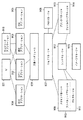
図11は、UI901におけるエラー表示処理を示すフローチャートである。まず、ステップS1101において、UI901にエラー発生が通知されると、そのエラーがコピーアプリケーション902、BOXアプリケーション904、PDLアプリケーション905などの各アプリケーションからのエラーイベントであるか否かを判定する。このエラーイベント情報には上記識別情報とテーブルに基づくファイル種別情報が含まれている。したがって、この判定処理により、エラーに係る画像ファイルの種別が、コピーアプリケーション902、BOXアプリケーション904、PDLアプリケーション905等により処理される画像印刷ファイルや、画像送信アプリケーション903により処理される画像送信ファイルであるかを判定することができる。
【0065】
ここで、これら各アプリケーションからのエラーイベントであれば、エラーに係るファイルの種別は送信またはプリント画像ファイルであるので、ステップS1102へ進み、サービスマンコールエラー(ディスクエラー)及び「電源をOFF/ONして下さい」というメッセージを表示し、使用者に電源のOFF/ONを促す。そして、使用者により電源OFFが指示されたら電源をOFFにする。
【0066】
一方、ステップS1101で、各アプリケーションからのエラーイベントでなく、UI901によるファイル読み出し時のエラーの場合はステップS1103へ進み、HDDから読み出したファイルの種別から表示画像の読み出しエラーか否かを判定する。ここで、表示画像の読み出しエラーであれば、ファイルの種別は表示用画像ファイルであるので、ステップS1104へ進み、「プレビュー画像を表示できません」というメッセージを表示する。この場合は、電源OFF/ONを行うような深刻なエラーとして処理する必要はない。また、ステップS1105で、表示画像の読み出しエラーでなければステップS1105へ進み、それ以外のサービスマンエラー(その他)表示を行う。この場合は、深刻なエラーであるサービスマンエラーとして、使用者に電源のOFF/ONを促す。そして、使用者により電源OFFが指示されたら電源をOFFにする。
【0067】
以上説明したように、本実施形態によれば、ハードディスク(HDD)に格納された画像を送信/プリント、或いはプレビュー表示するために、対応する形式のファイルを読み出し、エラーが発生した場合、そのファイルの種別に応じて、表示するエラーメッセージを変更することで、プレビュー画像のファイルを読み出す際のエラーなど深刻でないエラーが発生した場合、使用者はそのまま処理を続行することができる。
【0068】
また、エラーが発生した場合、そのファイルが、画像送信/印刷ファイルであれば、電源ON/OFFによるエラー制御を行い、ファイル表示処理であれば、エラー表示のみ行うので、エラー制御の柔軟性が向上し、エラー時の装置の処理効率の低下を最低限に抑えることができる。
【0069】
本実施形態では、ファイルの種別に基づいてエラー制御を変更しているが、本発明はこれに限るものではなく、ファイルの種別が何であるかにかかわらず、ファイル読み出しのエラーが生じた処理が送信処理、表示処理、又は印刷処理の何れかの処理であるかを判断し、直接、その判断結果に応じてエラー制御を変更するようにしてもよい。この場合の制御は、上述したフローチャートと同様に説明できる。
【0070】
尚、本実施形態では、ファイルエラーが生じた際に、図11のフローチャートの処理を開始するように制御したが、本発明はこれに限ることなく、ファイル読み出しが適正に行われなかった場合に広く適用なものである。また、本実施形態では、エラー報知の方法として、表示手段へのエラー表示を行うようにしているが、本発明はこれに限ることなく、例えば音声通知やプリント部による印刷通知等によるエラー報知の場合でも適用可能であることは言うまでもない。
【0071】
尚、本発明は複数の機器(例えば、ホストコンピュータ,インターフェース機器,リーダ,プリンタなど)から構成されるシステムに適用しても、1つの機器からなる装置(例えば、複写機,ファクシミリ装置など)に適用しても良い。
【0072】
また、本発明の目的は前述した実施形態の機能を実現するソフトウェアのプログラムコードを記録した記録媒体を、システム或いは装置に供給し、そのシステム或いは装置のコンピュータ(CPU若しくはMPU)が記録媒体に格納されたプログラムコードを読出し実行することによっても、達成されることは言うまでもない。
【0073】
この場合、記録媒体から読出されたプログラムコード自体が前述した実施形態の機能を実現することになり、そのプログラムコードを記憶した記録媒体は本発明を構成することになる。
【0074】
このプログラムコードを供給するための記録媒体としては、例えばフロッピー(登録商標)ディスク,ハードディスク,光ディスク,光磁気ディスク,CD−ROM,CD−R,磁気テープ,不揮発性のメモリカード,ROMなどを用いることができる。
【0075】
また、コンピュータが読出したプログラムコードを実行することにより、前述した実施形態の機能が実現されるだけでなく、そのプログラムコードの指示に基づき、コンピュータ上で稼働しているOS(オペレーティングシステム)などが実際の処理の一部又は全部を行い、その処理によって前述した実施形態の機能が実現される場合も含まれることは言うまでもない。
【0076】
更に、記録媒体から読出されたプログラムコードが、コンピュータに挿入された機能拡張ボードやコンピュータに接続された機能拡張ユニットに備わるメモリに書込まれた後、そのプログラムコードの指示に基づき、その機能拡張ボードや機能拡張ユニットに備わるCPUなどが実際の処理の一部又は全部を行い、その処理によって前述した実施形態の機能が実現される場合も含まれることは言うまでもない。
【0077】
【発明の効果】
以上説明したように本発明によれば、発生したエラーがファイルエラーの場合、ファイルの種別に応じて、表示するエラーメッセージを変更することが可能となる。
【図面の簡単な説明】
【図1】実施形態による画像形成システムの全体構成を示すブロック図である。
【図2】図1に示す画像形成装置の詳細な構成を示すブロック図である。
【図3】図2に示すスキャナ画像処理部213の構成を示すブロック図である。
【図4】本実施形態における画像形成装置の外観を示す図である。
【図5】図4に示す操作部112の構成を示す図である。
【図6】図2に示した画像形成装置の操作部の詳細な構成を示すブロック図である。
【図7】本実施形態の画像形成装置における初期画面である。
【図8】読込設定705を押下したときに表示されるポップアップウィンドウを示す図である。
【図9】画像形成装置におけるソフトウェア構成を示す図である。
【図10】本実施形態における画像処理の流れを示す図である。
【図11】UI901におけるエラー表示処理を示すフローチャートである。
【符号の説明】
100 LAN
101 パーソナルコンピュータ
102 公衆回線
110 画像形成装置
111 制御ユニット
112 操作部
113 スキャナ部
114 プリンタ部
120 画像形成装置
121 制御ユニット
122 操作部
123 スキャナ部
124 プリンタ部
130 画像形成装置
131 制御ユニット
132 操作部
133 スキャナ部
134 プリンタ部[0001]
BACKGROUND OF THE INVENTION
The present invention relates to an image processing apparatus and a processing method for storing an input image as a file of a file type corresponding to at least transmission processing, display processing, and printing processing, and reading and processing the stored file.
[0002]
[Prior art]
In recent years, with an increase in the capacity of memories and hard disks, for example, not only printing scanned images but also transmission via a network or a telephone line can be easily realized. In other words, such an apparatus having a large-capacity memory and hard disk stores images of a plurality of types of formats as files, from a single document image to a format suitable for transmission and a format suitable for image confirmation. It is possible to keep.
[0003]
[Problems to be solved by the invention]
However, in the above conventional example, when a desired file is transmitted / printed or when an image is confirmed, if a file read error is detected, the same error processing is performed. For this reason, the error rate increases by the number of files to be generated, and there is a problem that the power supply must be turned OFF / ON or a service person must be called each time. In particular, when displaying an image preview, even if a file error occurs, it is handled as a serious error even though it is not necessary to display a serious error message that prompts the user to turn off / on the power. It had been.
[0004]
The present invention has been made to solve the above-described problem, and provides an image processing apparatus and a processing method for changing an error message to be displayed according to a file type when an error that has occurred is a file error. For the purpose.
[0005]
[Means for Solving the Problems]
In order to achieve the above object, the present invention is an image processing apparatus that accumulates an input image as a file of a file type corresponding to at least transmission processing, display processing, and printing processing, and reads and processes the accumulated file. , When it is detected that the input image is not properly read when reading the stored file, and storage means for storing the input image as a file of a file type corresponding to at least transmission processing, display processing, and printing processing, And error processing means for controlling error notification according to the file type of the file.
In order to achieve the above object, the present invention converts an input image into a file of a predetermined format and stores it, reads the stored image file, and at least one of transmission processing, display processing, and printing processing. An image processing apparatus that performs processing, and stores an input image as a file for performing at least transmission processing, display processing, and printing processing Have When a file error is detected when reading the accumulated file And When the processing corresponding to the file is transmission processing or printing processing Dressed up Error processing by controlling the power supply of the device on / off Sase , A file error is detected when reading the accumulated file and Processing corresponding to the file display If it is a process D Error handling by error notification Show It is characterized by that.
[0006]
DETAILED DESCRIPTION OF THE INVENTION
Hereinafter, embodiments according to the present invention will be described in detail with reference to the drawings.
[0007]
FIG. 1 is a block diagram illustrating an overall configuration of an image forming system according to an embodiment. As shown in FIG. 1, the
[0008]
Further, other
[0009]
The personal computer (PC) 101 is connected to network transmission means such as the
[0010]
FIG. 2 is a block diagram showing a detailed configuration of the image forming apparatus shown in FIG. As shown in FIG. 2, the
[0011]
In the
[0012]
The operation unit I /
[0013]
A
[0014]
An image bus interface (Image Bus I / F) 205 is a bus bridge that connects a
[0015]
The following devices are arranged on the
[0016]
A scanner
[0017]
The
[0018]
Note that the
[0019]
FIG. 3 is a block diagram showing a configuration of the scanner
[0020]
Further, in order to determine whether the document is color or monochrome, the color
[0021]
Further, the character /
[0022]
On the other hand, the specific
[0023]
FIG. 4 is a diagram illustrating an appearance of the image forming apparatus according to the present embodiment. 4 scans an image on a document with a CCD line sensor (not shown), optically reads the image, generates raster image data, and outputs the raster image data. When the user sets an original on the
[0024]
The
[0025]
The
[0026]
FIG. 5 is a diagram showing the configuration of the
[0027]
A
[0028]
FIG. 6 is a block diagram showing a detailed configuration of the operation unit of the image forming apparatus shown in FIG. As described above, the
[0029]
In FIG. 6, user inputs from the
[0030]
Next, processing such as copy, transmission, and box in this embodiment will be described using a screen displayed on the
[0031]
FIG. 7 is an initial screen in the image forming apparatus of the present embodiment, and is also a standard screen displayed after setting each image forming function. In FIG. 7,
[0032]
A
[0033]
FIG. 8 is a diagram showing a pop-up window displayed when the read setting 705 is pressed. In FIG. 8,
[0034]
[0035]
Next, software executed by the
[0036]
FIG. 9 is a diagram illustrating a software configuration in the image forming apparatus. In FIG. 9,
[0037]
A
[0038]
Note that synchronization and image processing requests between the document processing units are performed via the
[0039]
First, local copy software processing in the above-described software configuration will be described. A copy setting is transmitted from the
[0040]
The
[0041]
Here, the completion of the scan image transfer is transmitted to the
[0042]
Further, when the
[0043]
On the other hand, the
[0044]
Here, the completion of the print image transfer is transmitted to the
[0045]
Next, in the case of a remote copy scan job or transmission job, the
[0046]
The
[0047]
Next, in the case of a remote copy print job, the
[0048]
A request for expanding the received image from the
[0049]
The
[0050]
Here, the completion of the print image transfer is transmitted to the
[0051]
Next, in the case of a PDL data development storage job, a request from the host PC that has input the PDL print is transmitted to the
[0052]
When the PDL is stored in the
[0053]
Next, for printing an image that has been developed and stored in PDL, the
[0054]
Next, at least an image file for transmission / printing and an image file for display to be displayed on the
[0055]
FIG. 10 is a diagram showing a flow of image processing in the present embodiment. As shown in the figure, the scanned or PDL developed image is processed from the left side to the right side shown in FIG. “◯” represents image processing, and “□” represents an image on the memory.
[0056]
First,
[0057]
Next, color space conversion processing (YUV → YCbCr) 1003 for the transmission image is performed. Then, when storing the converted image, a known JFIF header is described in advance in the
[0058]
Further, in order to display on the
[0059]
Next, when transmitting or printing, the stored transmission / print image file is read as an
[0060]
When the image is preview-displayed, the TIFF file of the stored image is read as an
[0061]
[Error display processing]
Next, in order to send / print or preview the image stored in the hard disk (HDD), a file in a corresponding format is read. If an error occurs, an error message is displayed according to the type of the file. The process of changing the will be described.
[0062]
In the above-described
[0063]
On the other hand, a TIFF file is directly read out by the
[0064]
FIG. 11 is a flowchart showing error display processing in the
[0065]
If it is an error event from each of these applications, the file type related to the error is a transmission or print image file, so the process proceeds to step S1102, and a serviceman call error (disk error) and “Power OFF / ON Message "and prompt the user to turn the power off / on. When the user instructs to turn off the power, the power is turned off.
[0066]
On the other hand, in step S1101, if it is not an error event from each application but an error at the time of file reading by the
[0067]
As described above, according to the present embodiment, in order to transmit / print or preview an image stored in a hard disk (HDD), a file in a corresponding format is read and an error occurs. By changing the error message to be displayed according to the type, if a non-serious error such as an error in reading a preview image file occurs, the user can continue the process.
[0068]
If an error occurs, if the file is an image transmission / print file, error control is performed by turning the power on / off. If the file display process, only error display is performed. It is possible to improve and minimize a decrease in processing efficiency of the apparatus at the time of error.
[0069]
In the present embodiment, the error control is changed based on the file type, but the present invention is not limited to this, and the process in which a file read error occurs regardless of what the file type is. It may be determined whether the process is a transmission process, a display process, or a printing process, and the error control may be changed directly according to the determination result. The control in this case can be explained in the same manner as the flowchart described above.
[0070]
In the present embodiment, control is performed so that the processing of the flowchart of FIG. 11 is started when a file error occurs. However, the present invention is not limited to this, and when the file is not read properly. Widely applicable. In this embodiment, error display is performed as an error notification method. However, the present invention is not limited to this. For example, error notification by voice notification or print notification by a printing unit is possible. Needless to say, this is applicable even in cases.
[0071]
Even if the present invention is applied to a system composed of a plurality of devices (for example, a host computer, an interface device, a reader, a printer, etc.), it is applied to an apparatus (for example, a copier, a facsimile machine, etc.) composed of a single device. It may be applied.
[0072]
Another object of the present invention is to supply a recording medium in which a program code of software realizing the functions of the above-described embodiments is recorded to a system or apparatus, and the computer (CPU or MPU) of the system or apparatus stores the recording medium in the recording medium. Needless to say, this can also be achieved by reading and executing the programmed program code.
[0073]
In this case, the program code itself read from the recording medium realizes the functions of the above-described embodiment, and the recording medium storing the program code constitutes the present invention.
[0074]
As a recording medium for supplying the program code, for example, a floppy (registered trademark) disk, a hard disk, an optical disk, a magneto-optical disk, a CD-ROM, a CD-R, a magnetic tape, a nonvolatile memory card, a ROM, or the like is used. be able to.
[0075]
Further, by executing the program code read by the computer, not only the functions of the above-described embodiments are realized, but also an OS (operating system) operating on the computer based on the instruction of the program code. It goes without saying that a case where the function of the above-described embodiment is realized by performing part or all of the actual processing and the processing is included.
[0076]
Further, after the program code read from the recording medium is written in a memory provided in a function expansion board inserted into the computer or a function expansion unit connected to the computer, the function expansion is performed based on the instruction of the program code. It goes without saying that the CPU or the like provided in the board or the function expansion unit performs part or all of the actual processing and the functions of the above-described embodiments are realized by the processing.
[0077]
【The invention's effect】
As described above, according to the present invention, when the error that has occurred is a file error, the error message to be displayed can be changed according to the type of the file.
[Brief description of the drawings]
FIG. 1 is a block diagram illustrating an overall configuration of an image forming system according to an embodiment.
FIG. 2 is a block diagram showing a detailed configuration of the image forming apparatus shown in FIG.
3 is a block diagram showing a configuration of a scanner
FIG. 4 is a diagram illustrating an appearance of an image forming apparatus according to the present embodiment.
5 is a diagram showing a configuration of an
6 is a block diagram illustrating a detailed configuration of an operation unit of the image forming apparatus illustrated in FIG. 2;
FIG. 7 is an initial screen in the image forming apparatus according to the present exemplary embodiment.
FIG. 8 is a diagram showing a pop-up window displayed when a read setting 705 is pressed.
FIG. 9 is a diagram illustrating a software configuration in the image forming apparatus.
FIG. 10 is a diagram showing a flow of image processing in the present embodiment.
FIG. 11 is a flowchart showing error display processing in a
[Explanation of symbols]
100 LAN
101 Personal computer
102 Public line
110 Image forming apparatus
111 Control unit
112 Operation unit
113 Scanner section
114 Printer
120 Image forming apparatus
121 Control unit
122 Operation unit
123 Scanner unit
124 Printer
130 Image forming apparatus
131 Control unit
132 Operation unit
133 Scanner section
134 Printer section
Claims (9)
入力画像を少なくとも送信処理、表示処理、及び印刷処理に対応するファイル種別のファイルとして蓄積する蓄積手段と、
前記蓄積したファイルを読み出す際に適正に読み出されなかったことが検出された場合、そのファイルのファイル種別に応じてエラー報知の制御を行うエラー処理手段とを有することを特徴とする画像処理装置。An image processing apparatus that stores an input image as a file of a file type corresponding to at least transmission processing, display processing, and printing processing, and reads and processes the stored file,
Storage means for storing an input image as a file of a file type corresponding to at least transmission processing, display processing, and printing processing;
An image processing apparatus comprising: error processing means for controlling error notification according to the file type of the file when it is detected that the stored file is not read properly when the stored file is read .
入力画像を少なくとも送信処理、表示処理、及び印刷処理を行うためのファイルとして蓄積する蓄積手段を有し、
前記蓄積したファイルを読み出す際にファイルエラーが検出された場合で且つ前記ファイルに対応する処理が送信処理または印刷処理である場合に装置の電源をON/OFF制御することによるエラー処理を行わせ、
前記蓄積したファイルを読み出す際にファイルエラーが検出された場合で且つ前記ファイルに対応する処理が表示処理である場合にエラー通知によるエラー処理を行わせることを特徴とする画像処理装置。An image processing apparatus that converts an input image into a file of a predetermined format and stores it, reads the stored image file, and performs at least one of transmission processing, display processing, and printing processing,
Has a storage means for storing the input image at least the transmission processing, as a file for performing display processing, and the printing process,
Line Align the error processing by the processing corresponding to and the file if the file error in reading the accumulated file is detected to control ON / OFF the power of the equipment in the case of transmission processing or printing process ,
The image processing apparatus according to claim processing and corresponding to the file when the file error is detected that causes I line error processing by the error notification when a display processing when reading the accumulated file.
入力画像を少なくとも送信処理、表示処理、及び印刷処理に対応するファイル種別のファイルとして蓄積する蓄積工程と、
前記蓄積したファイルを読み出す際に適正に読み出されなかったことが検出された場合、そのファイルのファイル種別に応じてエラー報知の制御を行うエラー処理工程とを有することを特徴とする画像処理装置の処理方法。A processing method of an image processing apparatus for storing an input image as a file of a file type corresponding to at least transmission processing, display processing, and printing processing, and reading and processing the stored file,
A storage step of storing the input image as a file of a file type corresponding to at least transmission processing, display processing, and printing processing;
An image processing apparatus comprising: an error processing step of controlling error notification according to a file type of the file when it is detected that the stored file is not read properly when the stored file is read Processing method.
入力画像を少なくとも送信処理、表示処理、及び印刷処理を行うためのファイルとして蓄積手段に蓄積させ、
前記蓄積したファイルを読み出す際にファイルエラーが検出された場合で且つ前記ファイルに対応する処理が送信処理または印刷処理である場合に装置の電源をON/OFF制御することによるエラー処理を行わせ、
前記蓄積したファイルを読み出す際にファイルエラーが検出された場合で且つ前記ファイルに対応する処理が表示処理である場合にエラー通知によるエラー処理を行わせることを特徴とする画像処理装置の処理方法。A processing method of an image processing apparatus that converts an input image into a file of a predetermined format and stores it, reads the stored image file, and performs at least one of transmission processing, display processing, and printing processing,
At least the transmission processing an input image, display processing, and is stored in the storage means as a file for printing process,
Line Align the error processing by the processing corresponding to and the file if the file error in reading the accumulated file is detected to control ON / OFF the power of the equipment in the case of transmission processing or printing process ,
Processing of the image processing apparatus according to claim processing and corresponding to the file when the file error is detected that causes I line error processing by the error notification when a display processing when reading the accumulated file Method.
Priority Applications (1)
| Application Number | Priority Date | Filing Date | Title |
|---|---|---|---|
| JP2002287057A JP3927894B2 (en) | 2002-09-30 | 2002-09-30 | Image processing apparatus and processing method thereof |
Applications Claiming Priority (1)
| Application Number | Priority Date | Filing Date | Title |
|---|---|---|---|
| JP2002287057A JP3927894B2 (en) | 2002-09-30 | 2002-09-30 | Image processing apparatus and processing method thereof |
Publications (3)
| Publication Number | Publication Date |
|---|---|
| JP2004128665A JP2004128665A (en) | 2004-04-22 |
| JP2004128665A5 JP2004128665A5 (en) | 2005-07-07 |
| JP3927894B2 true JP3927894B2 (en) | 2007-06-13 |
Family
ID=32279971
Family Applications (1)
| Application Number | Title | Priority Date | Filing Date |
|---|---|---|---|
| JP2002287057A Expired - Fee Related JP3927894B2 (en) | 2002-09-30 | 2002-09-30 | Image processing apparatus and processing method thereof |
Country Status (1)
| Country | Link |
|---|---|
| JP (1) | JP3927894B2 (en) |
Families Citing this family (4)
| Publication number | Priority date | Publication date | Assignee | Title |
|---|---|---|---|---|
| SE531071C2 (en) * | 2005-12-16 | 2008-12-09 | Delaval Holding Ab | Milking system and method for generating and communicating error messages in such a milking system |
| JP2007174068A (en) * | 2005-12-20 | 2007-07-05 | Ricoh Co Ltd | Image forming apparatus |
| JP7073790B2 (en) | 2018-03-07 | 2022-05-24 | 富士フイルムビジネスイノベーション株式会社 | Information processing equipment and programs |
| JP6746632B2 (en) * | 2018-06-07 | 2020-08-26 | キヤノン株式会社 | Image forming apparatus, control method of image forming apparatus, and program |
-
2002
- 2002-09-30 JP JP2002287057A patent/JP3927894B2/en not_active Expired - Fee Related
Also Published As
| Publication number | Publication date |
|---|---|
| JP2004128665A (en) | 2004-04-22 |
Similar Documents
| Publication | Publication Date | Title |
|---|---|---|
| US7414748B2 (en) | Image input/output apparatus, method of controlling image input/output apparatus, image input/output system, and storage media | |
| US7532348B2 (en) | Image input/output control method and image input/output apparatus | |
| US8004698B2 (en) | Image forming apparatus for combining a scanned image with other image data and printing the combined image in black and white or color based on a set mode | |
| JP3797669B2 (en) | Image forming apparatus and image forming method | |
| US20050286081A1 (en) | Image input/output apparatus, control method of image input/output apparatus, image input/output system, and storage medium thereof | |
| JP4147255B2 (en) | Image processing apparatus, image processing control method, program, and storage medium | |
| JP3927894B2 (en) | Image processing apparatus and processing method thereof | |
| US7072060B2 (en) | Print control apparatus, print control method, and memory medium | |
| JP2004090423A (en) | Image formation device and its processing method | |
| JP2006180343A (en) | Image input-output device | |
| JP2006211003A (en) | Image processor | |
| JP2004128882A (en) | Image input/output apparatus, and method therefor | |
| JP2003051951A (en) | Image input output device and control method therefor | |
| JP2006166134A (en) | Image communication equipment, its control method, program, and storage medium | |
| JP4078041B2 (en) | Image input / output device, image input / output method, image input / output system, and storage medium | |
| JP2006287707A (en) | Image processor | |
| JP2003110783A (en) | File managing apparatus, image forming device, method for deleting file, storage medium and program | |
| JP2004172744A (en) | Color image input/output apparatus | |
| JP2004032054A (en) | Image input/output device | |
| JP2004088417A (en) | Image processing device, image processing method, program for image processing device control, and recording medium | |
| JP2002290749A (en) | Image processing apparatus | |
| JPH10243229A (en) | Image-processing unit, electronic device and control method therefor | |
| JP2003330241A (en) | Color image input/output device | |
| JP2006165614A (en) | Multifunction system provided with automatic management function | |
| JP2006240151A (en) | Image output unit |
Legal Events
| Date | Code | Title | Description |
|---|---|---|---|
| A521 | Written amendment |
Free format text: JAPANESE INTERMEDIATE CODE: A523 Effective date: 20041026 |
|
| A621 | Written request for application examination |
Free format text: JAPANESE INTERMEDIATE CODE: A621 Effective date: 20041026 |
|
| A977 | Report on retrieval |
Free format text: JAPANESE INTERMEDIATE CODE: A971007 Effective date: 20060310 |
|
| A131 | Notification of reasons for refusal |
Free format text: JAPANESE INTERMEDIATE CODE: A131 Effective date: 20060508 |
|
| A521 | Written amendment |
Free format text: JAPANESE INTERMEDIATE CODE: A523 Effective date: 20060615 |
|
| TRDD | Decision of grant or rejection written | ||
| A01 | Written decision to grant a patent or to grant a registration (utility model) |
Free format text: JAPANESE INTERMEDIATE CODE: A01 Effective date: 20070219 |
|
| A61 | First payment of annual fees (during grant procedure) |
Free format text: JAPANESE INTERMEDIATE CODE: A61 Effective date: 20070305 |
|
| R150 | Certificate of patent or registration of utility model |
Free format text: JAPANESE INTERMEDIATE CODE: R150 |
|
| FPAY | Renewal fee payment (event date is renewal date of database) |
Free format text: PAYMENT UNTIL: 20100309 Year of fee payment: 3 |
|
| FPAY | Renewal fee payment (event date is renewal date of database) |
Free format text: PAYMENT UNTIL: 20110309 Year of fee payment: 4 |
|
| FPAY | Renewal fee payment (event date is renewal date of database) |
Free format text: PAYMENT UNTIL: 20120309 Year of fee payment: 5 |
|
| FPAY | Renewal fee payment (event date is renewal date of database) |
Free format text: PAYMENT UNTIL: 20130309 Year of fee payment: 6 |
|
| FPAY | Renewal fee payment (event date is renewal date of database) |
Free format text: PAYMENT UNTIL: 20140309 Year of fee payment: 7 |
|
| LAPS | Cancellation because of no payment of annual fees |