JP3906331B2 - RF-ID tag for baggage and manufacturing method thereof - Google Patents
RF-ID tag for baggage and manufacturing method thereof Download PDFInfo
- Publication number
- JP3906331B2 JP3906331B2 JP2002089089A JP2002089089A JP3906331B2 JP 3906331 B2 JP3906331 B2 JP 3906331B2 JP 2002089089 A JP2002089089 A JP 2002089089A JP 2002089089 A JP2002089089 A JP 2002089089A JP 3906331 B2 JP3906331 B2 JP 3906331B2
- Authority
- JP
- Japan
- Prior art keywords
- module
- sheet
- baggage
- tag
- antenna
- Prior art date
- Legal status (The legal status is an assumption and is not a legal conclusion. Google has not performed a legal analysis and makes no representation as to the accuracy of the status listed.)
- Expired - Fee Related
Links
Images


Landscapes
- Credit Cards Or The Like (AREA)
Description
【0001】
【発明の属する技術分野】
本発明は、託送される手荷物に取り付けられて、非接触で手荷物所有者等を特定させるための手荷物用RF−IDタグおよびその製造方法に関する。
【0002】
【従来の技術】
近年、RF−ID(Radio Frequency Identification)と称される非接触型ICメディア(非接触型ICカード等)に関する技術が急速に進歩してきており、これは、基材上に印刷工程等によりコイル状のアンテナが形成され、このアンテナの両端にICモジュール(ICベアチップ単体も含む)が実装されることで作製される。そして、その使用も多岐にわたっており、そのうち、託送される手荷物に取り付けられるRF−IDタグがある。このようなRF−IDタグは使用に際して利便性が要求されると共に、その製造においては量産性、低コスト化が望まれており、一方で使用環境によって耐久性に優れていることが必要である。
【0003】
従来、例えば空港での搭乗の際に託送される手荷物や、乗船の際に託送される手荷物に取り付けられるバッゲージICタグは、手荷物の提げ手等にループ状に接着される。このようなバッゲージICタグは、感熱シート、RF−IDモジュール、剥離紙とで形成された構成のものが殆どである。この場合、感熱タッグ紙には、託送する際の所定の情報がサーマルプリンタにより印字されて、視認情報とタグに記憶された電子的データとにより当該手荷物の所有者や行き先等を特定している。
【0004】
上記のようなバッゲージICタグの製造は、一方面に粘着剤が塗布された感熱タッグ紙と、RF−IDモジュールが形成されたフィルムと、剥離剤が全面に塗布された剥離紙とが用意され、上記感熱タッグ紙の粘着剤面にRF−IDモジュールのフィルムを貼り付け、さらに当該面に粘着剤を塗布し、当該粘着剤面に剥離剤面を対向させて剥離紙を剥離可能に接着させるものである。
【0005】
【発明が解決しようとする課題】
しかしながら、上記のようなバッゲージICタグは、剥離紙を剥離し、ループ状にして手荷物の提げて等に取り付ける場合、当該剥離紙が剥離された全面が粘着剤面となることから、ループの内側部分の粘着剤で当該提げ手等に接着されたり、取り外した際に粘着剤が残ることもあって、使用の利便性に欠けるという問題がある。また、上記バッゲージICタグを作製するに際して、RF−IDモジュールが形成されるフィルムが高価であると共に、これを貼着する工程や、その後の粘着剤塗布の工程が必要となって量産性に欠けるという問題がある。
【0006】
そこで、本発明は上記課題に鑑みなされたもので、使用の際の利便性、耐久性を向上させ、製造における量産性、低コスト化を図る手荷物用RF−IDタグおよびその製造方法を提供することを目的とする。
【0007】
【課題を解決するための手段】
上記課題を解決するために、請求項1の発明では、ICモジュール、または接続ランド部が形成された基材上に当該ICモジュールが実装されたICモジュールユニットを、アンテナ部に実装させたRF−IDモジュールを備え、ループ状にされて手荷物に取り付けられる手荷物用RF−IDタグであって、前記ICモジュールに記憶された情報と関連する情報が所定の印字手段により印字される情報表示シートと、前記情報表示シートと粘着剤により積層されるもので、長手方向の両端の少なくとも一方に、前記ループ状とさせる前記粘着剤を表出させるための剥離剤が形成され、当該剥離剤部分が剥離自在な保護シートと、前記情報表示シートと前記保護シートとの間に介在され、剥離性の樹脂がコーティングされた剥離機能シートの平面上に導電性インキにより形成した前記アンテナ部に前記ICモジュール若しくはICモジュールユニットを実装させて前記情報表示シート若しくは前記保護シート上に粘着剤で転写させることにより前記RF−ICモジュールを構成させ、または、剥離性の樹脂がコーティングされた剥離機能シートの平面上に導電性インキにより形成した前記アンテナ部を前記情報表示シート若しくは前記保護シート上に粘着剤で転写させて前記ICモジュール若しくはICモジュールユニットを実装させることにより前記RF−IDモジュールを構成させる転写RF−IDモジュールと、を有する構成とする。
【0008】
請求項2の発明では、前記ICモジュールに記憶され、前記情報表示シートに印字される情報は、少なくとも前記手荷物に関する一部または全部の情報である構成である。
【0009】
請求項3の発明では、ICモジュール、または接続ランド部が形成された基材上に当該ICモジュールが実装されたICモジュールユニットを、アンテナ部に実装させたRF−IDモジュールを備え、ループ状にされて手荷物に取り付けられる手荷物用RF−IDタグの製造方法であって、被形成物が剥離自在な剥離性の樹脂がコーティングされた剥離機能シートの平面上に、導電性インキにより前記アンテナ部が形成される工程と、前記アンテナ部に前記ICモジュールまたはICモジュールユニットが実装されることで前記RF−IDモジュールが形成される工程と、前記情報表示シート、または長手方向の両端の少なくとも一方に前記ループ状とさせる粘着剤を表出させるための剥離剤が形成されて当該剥離剤部分が剥離自在とされる保護シートで構成される転写シートに、前記RF−IDモジュールを粘着剤により接着させることで前記剥離機能シートより剥離させて転写させる工程と、前記転写シートにおける転写された前記RF−IDモジュール側に、当該転写シートが前記情報表示シートの場合には前記保護シートを、当該転写シートが前記保護シートの場合には前記情報表示シートを接着させる工程と、を含む構成とする。
【0010】
請求項4の発明では、ICモジュール、または接続ランド部が形成された基材上に当該ICモジュールが実装されたICモジュールユニットを、アンテナ部に実装させたRF−IDモジュールを備え、ループ状にされて手荷物に取り付けられる手荷物用RF−IDタグの製造方法であって、被形成物が剥離自在な剥離性の樹脂がコーティングされた剥離機能シートの平面上に、導電性インキにより前記アンテナ部が形成される工程と、前記情報表示シート、または長手方向の両端の少なくとも一方に前記ループ状とさせる粘着剤を表出させるための剥離剤が形成されて当該剥離剤部分が剥離自在とされる保護シートで構成される転写シートに、前記アンテナ部を粘着剤により接着させることで前記剥離機能シートより剥離させて転写させる工程と、前記転写シート上で、転写された前記アンテナ部に前記ICモジュールまたはICモジュールユニットが実装されることで前記RF−IDモジュールが形成される工程と、前記転写シートにおける転写された前記RF−IDモジュール側に、当該転写シートが前記情報表示シートの場合には前記保護シートを、当該転写シートが前記保護シートの場合には前記情報表示シートを接着させる工程と、を含む構成とする。
【0011】
請求項5の発明では、前記ICモジュールに記憶され、前記情報表示シートに印字される情報は、少なくとも前記手荷物に関する一部または全部の情報である構成である。
【0012】
このように、アンテナ部およびICモジュールを有する手荷物用RF−IDタグであって、剥離性の樹脂がコーティングされた剥離機能シートの平面上に導電性インキにより形成されたアンテナ部に実装される転写RF−IDモジュールが情報表示シートと保護シートとの間の何れかに転写によって介在され、長手方向の少なくとも一方端で剥離自在としてループ状とさせるための粘着剤を表出させる。すなわち、ループ状とさせるための粘着剤が接着させる部分のみで表出させることとなり、取り付け対象に当該粘着剤で付着することがなく、使用の際の利便性を向上させることが可能となる。また、転写RF−IDモジュールが感熱シートと保護シートとにより物理的、機械的ストレスに対して強度が増して耐久性を向上させることが可能となるものである。
【0013】
さらに、少なくともアンテナ部を剥離機能シート上に形成し、転写シートに転写させることで作製する。すなわち、製造工程における加熱や圧力印加の工程を剥離機能シート上で行わせることから、使用される基材が加熱や圧力を考慮せずともよく、量産性、低コスト化を図ることが可能となる。
【0014】
【発明の実施の形態】
以下、本発明の好ましい実施形態を図により説明する。図1に、本発明に係る手荷物用RF−IDタグの第1実施形態の構成図を示す。図1(A)は手荷物用RF−IDタグの縦側断面図、図1(B)は搭載される転写RF−IDモジュールの構成図、図1(C)は剥離シートの構成図である。
【0015】
図1(A)に示す手荷物用RF−IDタグ11は、情報表示シートである感熱シート12、アンテナ部とICモジュールとを備える転写RF−IDモジュール13および保護シート14が積層されて構成される。感熱シート12は、ICモジュールに記憶された情報と関連する情報が所定の印字手段により印字されるもので、感熱シート基材21の一方面に粘着剤22が塗布され、他方面に感熱発色剤が塗布された感熱剤層23が形成されたものである。感熱シート基材21は、例えば紙、樹脂フィルム等が使用できる。粘着剤22は、公知の粘着剤で十分であり、最終的な製品形態となったときに永久接着されるものが使用される。なお、情報表示シートとして、上記感熱剤層23を形成させないこととしてもよく、この場合には印字手段として例えばインクジェットプリンタ等で情報印字を行えばよい。
【0016】
上記保護シート14は、感熱シート12と粘着剤22により積層されるもので、長手方向の両端の少なくとも一方における剥離部14A,14Bが切取ライン15A,15Bにより分離自在となっており、図1(A)、(C)に示すように、当該剥離部14A,14Bの一方面(転写RF−IDモジュール13側)に、タグとしてループ状とさせるための上記粘着剤22の一部を表出させるための剥離剤16A,16Bが塗布されて形成され、当該剥離剤16A,16B部分で当該剥離部15A,15Bが剥離自在なっている。この保護シート14は、そのシート基材として紙が経済上最も好ましいが、ポリエチレンテレフタレート、ポリブチレンテレフタレート、ポリエチレンナフタレートのようなポリエステルフィルムや、公知の樹脂フィルムが使用される。また、剥離部14A,14Bに塗布される剥離剤16A,16Bとしては、例えばシリコーン剤等のような高分子物質の剥離剤がある。
【0017】
上記転写RF−IDモジュール13は、図1(B)に示すように、感熱シート12と保護シート14との間に介在され、後述する他部材上に導電性インキにより形成したアンテナ部31にICモジュール32を実装させて感熱シート12上に粘着剤22で転写させることにより形成したものである。アンテナ部31は、一例として平面コイル状に所定数巻回させたアンテナパターンであり、その両端がランド部31A,31Bとなる。このランド部31Aから内側方向のアンテナパターン上に絶縁剤層33が形成され、当該ランド部31Aより絶縁剤層33上を経由して短絡ライン34が形成される。この短絡ライン34の端部がランド部35となる。
【0018】
すなわち、上記アンテナパターン(ランド部31A,31Bを含む)、絶縁剤層33、短絡ライン34およびランド部35で上記アンテナ部31が構成される。アンテナパターンは、使用されるICモジュールやRF−IDタグとしての使用形態に応じて適宜設計されるものであり、ランド部31A,31B間の距離がICモジュール32の端子間距離に合致したり、1回のみの周回である場合等の設計されるパターンによっては絶縁剤層33および短絡ライン34(ランド部35)を省略することができる。
【0019】
また、上記アンテナ部31は、導電性インキを用いて例えばスクリーン印刷により上記アンテナパターン、短絡ライン34およびランド部35が形成され、絶縁性部材(絶縁性インキ)を用いて例えば上記同様のスクリーン印刷により絶縁剤層33が形成される。この導電性インキは、印刷後に熱、赤外線、紫外線、電子線等により固化されるもので、例えば、アサヒ化学研究所製LS−411AW(商品名)、藤倉化成製FA−353(商品名)、東洋紡績製DWP−026(商品名)を使用することができる。なお、絶縁剤層33の形成として、絶縁フィルムや紙類または絶縁テープ類を対応のアンテナパターン上に貼着させることとしてもよい。
【0020】
そして、ランド部31Bとランド部35と間にICモジュール(内部構成は図9で示す)32が少なくとも密着状態で電気的に接続されることで実装される。密着状態とさせる方法として、各ランド部31B,35とICモジュール32の端子間に異方性導電フィルム、異方性導電ペースト、絶縁樹脂、両面接着テープ等を介在させる方法がある。これらを塗布する方法としては、ディスペンス法、印刷法、スプレイ法等があるが、異方性導電ペーストや絶縁樹脂を用いる場合にはディスペンス法で塗布させることが好ましい。
【0021】
一方、ICモジュール32の接続端子部分は、必要に応じて金属電解メッキ、スタッド、無電解金属メッキ、導電性樹脂の固定化などによるバンプが形成される。このICモジュール32の実装の際には、必要な圧力を加えることとしてもよく、また接着テープによる実装する場合としてその材料に応じて熱、光、電磁波、超音波等のエネルギを加えることとしてもよい。また、実装後の接着部分の固定化を十分とさせるために後硬化を行ってもよい。なお、実装されたICモジュール32を保護するために、当該実装部分全体または一部分をグローブトップ材やアンダーフィル材で被覆保護してもよい。
【0022】
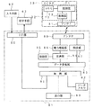
そこで、図2に、図1の手荷物用RF−IDタグ製造の概念図を示す。図2は、手荷物用RF−IDタグ製造システム41を示したもので、剥離機能シート42が例えばエンドレスで搬送される。この剥離機能シート42は、樹脂フィルムや不織布上にフッ素樹脂基材、フッ素樹脂、シリコーン等の剥離性部材をコーティングしたものや、不織布、各種の無機または有機の繊維(ガラス繊維、アルミナ繊維、ポリエステル繊維、ポリアミド繊等)で形成される織布、紙、またはこれらを組み合わせたシート上に剥離性の樹脂をコーティングしたものが適宜使用される。転写前のRF−IDモジュール13Aのアンテナ部31を高温処理すると導電性を向上させることができることを考慮すれば、剥離機能シート42のシート基材を、耐熱性を有するフッ素樹脂基材、シリコーンコートポリイミド基材、フッ素樹脂含有ガラス布を使用することが望ましい。この剥離機能シート42は、転写後にまた新たなアンテナ部31を形成することができ、低コスト化に貢献している。
【0023】
上記搬送される剥離機能シート42の上方には、搬送方向順に、導電性インキ印刷手段43、固化手段(ここでは加熱とする)44、絶縁性インキ印刷手段45、固化手段(ここでは加熱とする)46、導電性インキ印刷手段47、固化手段(ここでは加熱とする)48が配置される。導電性インキ印刷手段43は、上記アンテナパターンを上記導電性インキにより印刷して形成させるためのものであり、固化手段44は印刷されたアンテナパターンを加熱して固化するためのものである。
【0024】
また、絶縁性インキ印刷手段45は、アンテナパターンの所定部分上に上記絶縁剤層33を絶縁性インキにより印刷して形成させるためのものであり、固化手段46は印刷された絶縁剤層33を加熱して固化させるためのものである。さらに、導電性インキ印刷手段47は、上記絶縁剤層33上に短絡ライン34(ランド部35)を上記導電性インキにより印刷して形成させるためのものであり、固化手段48は印刷された短絡ライン34(ランド部35)を加熱して固化するためのものである。
【0025】
また、搬送される剥離機能シート42の上方であって、固化手段48の搬送方向後方にICモジュール実装手段49が配置される。このICモジュール実装手段49は、上記ICモジュール32の実装の方法に応じたもので、例えばその接続端子をバンプとした場合には当該ICモジュール32をアンテナ部31のランド部31Bと短絡ライン34のランド部35上に押圧して電気的接続させることで実装するものである。なお、上述のように、ICモジュール32が実装されたRF−IDモジュール13上に保護皮膜を形成させる場合には、当該ICモジュール実装手段49の後段にさらに、保護皮膜材印刷手段および固化手段が適宜配置される。
【0026】
一方、転写シートとなる上記粘着剤22が塗布された感熱シート12の連続体が、上記搬送される剥離機能シート42の搬送方向端部部分で重なるように転写シート連続体供給部50より供給されるもので、RF−IDモジュール13Aの転写後に上記保護シート14の連続体が当該転写側に重なるように保護シート連続体供給部51より供給される。そして、保護シート14が重ね接着された手荷物用RF−IDタグ11の連続体をRF−IDタグ連続体収納部52により巻取収納させる構成である。
【0027】
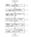
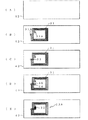
そこで、図3に図1の手荷物用RF−IDタグ製造のフローチャートを示すと共に、図4および図5に図3の手荷物用RF−IDタグ製造における各段階の説明図を示す。なお、図4および図5は単体のまたは一部分として図示してある。図3において、まず、図4(A)に示す剥離機能シート42上に、上記導電性インキ印刷手段43により、図4(B)に示すようなアンテナ部31の一部を構成するアンテナパターン(ランド部31A,31B)が印刷され、固化手段44により固化される(ステップ(S)1)。
【0028】
続いて、上記絶縁性インキ印刷手段45により、図4(C)に示すようなアンテナ部31の一部を構成する絶縁剤層33が上記アンテナパターンの所定部分上に印刷され、固化手段46により固化する(S2)。また、上記導電性インキ印刷手段47により、図4(D)に示すような短絡ライン34およびランド部35が印刷され、固化手段48により固化する(S3)。これによりアンテナ部31が形成されたことになる。そして、図4(E)に示すように、ICモジュール実装手段49において形成されたアンテナ部31のランド部31B,35間にICモジュール32を実装することによりRF−IDモジュール13Aが形成される(S4)。
【0029】
続いて、図5(A)に示すような剥離機能シート42上に形成されたRF−IDモジュール13Aを、転写シート連続体供給部50より供給される感熱シート12の粘着剤層22に接着させることで、図5(B)に示しように、当該RF−IDモジュール13Aを剥離機能シート42上より剥離させて感熱シート12に転写させる(S5)。そして、図5(C)に示すように、上記RF−IDモジュール13Aを転写した転写RF−IDモジュール13側の感熱シート12上に、保護シート連続体供給部51より供給される保護シート14を重ね合わせることにより接着させて手荷物用RF−IDタグ11の連続体とし、RF−IDタグ連続体収納部52に巻き取るものである(S6)。その後、使用形態に合わせて、手荷物用RF−IDタグ11は、単一毎あるいは所定の複数毎に切断されるものである。
【0030】
上記のような手荷物用RF−IDタグ11は、アンテナ部31およびICモジュール32を有する転写RF−IDモジュール13が感熱シート12と保護シート14との間に介在させ、長手方向の両端で剥離剤16A,16Bが塗布された剥離部14A,14Bを切取ライン15A,15Bで剥離自在とさせことでループ状とするための粘着剤22を表出させる。すなわち、ループ状とさせるための粘着剤22が接着させる部分のみで表出させることとなり、取り付け対象に当該粘着剤22で付着することがなく、使用の際の利便性を向上させることができるようになる。また、転写RF−IDモジュール13が感熱シート12と保護シート14とにより物理的、機械的ストレスに対して強度が増して耐久性を向上させることが可能となるものである。
【0031】
さらに、少なくともアンテナ部31を剥離機能シート42上に形成し、転写シートとなる感熱シート12に転写させることで作製する。すなわち、製造工程における加熱や圧力印加の工程を剥離機能シート上で行わせることから、使用される基材が加熱や圧力を考慮せずともよく、量産性、低コスト化がはかれるものである。
【0032】
なお、上記実施形態では、ICモジュール32の実装を転写シートとなる感熱シート12による転写前に行わせた場合を示しているが、転写後であって保護シート14の重ね合わせ前に実装してもよい。また、上記実施形態では、保護シート14の両端に剥離剤16A,16Bが塗布された剥離部14A,14Bを切取ライン15A,15Bで剥離自在とさせる場合を示したが、粘着剤22の粘着力によっては、剥離剤が塗布された剥離部を長手方向の一方端のみとすることもできる。これらのことは、以下の第2実施形態においても同様であり、そこではICモジュール32の実装に替えて、インターポーザ36の実装となる。
【0033】
一方、上記実施形態における手荷物用RF−IDタグ11を製造するに際して、図2における転写シート連続体供給部50より、一方面に粘着剤が塗布された保護シート14を供給することとして転写させ、上記保護シート連続体供給部51に替えて、感熱シート(この場合、粘着剤22は不要)12の連続体供給部として当該感熱シート12を供給させることとしてもよい。この場合、ICモジュール32の実装を、上記の方法以外に、当該上記保護シート14に塗布される粘着剤の粘着性を利用して固定化することも可能である。このことは、以下の第2実施形態においても同様である。
【0034】
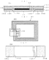
次に、図6に、本発明に係る手荷物用RF−IDタグの第2実施形態の構成図を示す。図6(A)は手荷物用RF−IDタグの縦側断面図、図6(B)は搭載される転写RF−IDモジュールの構成図、図6(C)は剥離シートの構成図である。そして、図6(A)および(C)に示す構成は図1(A)、(C)と同様である。すなわち、転写RF−IDモジュール13の構成を図1と異ならせたものである。
【0035】
そこで、図7に、図6のアンテナ部およびインターポーザの説明図を示す。図7(A)、(B)および図6(B)において、転写RF−IDモジュール13は、導電性インキによりアンテナ部31が形成され、ICモジュールユニットであるインターポーザ36が実装されたものである。アンテナ部31は、図7(A)に示すように、一例として平面コイル状に所定数巻回させたアンテナパターンであり、その両端がランド部31A,31Bとなる。
【0036】
上記アンテナパターンは、使用されるICモジュールやRF−IDタグとしての使用形態に応じて適宜設計されるものであり、アンテナ部31のランド部31A,31Bを共通化させることでこのインターポーザ32を共通化させることができる。このアンテナ部31は、上述のように、例えば、アサヒ化学研究所製LS−411AW(商品名)、藤倉化成製FA−353(商品名)、東洋紡績製DWP−026(商品名)の導電性インキを用いて例えばスクリーン印刷により上記アンテナパターンを形成し、印刷後に熱、赤外線、紫外線、電子線等により固化されるものである。
【0037】
上記インターポーザ32は、図7(B)に示すように、インターポーザ基材37上に、上記同様の導電性インキにより導電性パターン38が形成されたもので、接続ランド部38A,38Bと、接続ランド部38Cとが絶縁状態で離隔されて形成される。この接続ランド部38B,38C間にICモジュール32が実装される。また、接続ランド部38A,38B間の導電性パターン38上には絶縁剤層39が形成される。すなわち、接続ランド部38Aとアンテナ部31のランド部31Aとが電気的接続され、接続ランド部38Cとアンテナ部31のランド部31Bとが電気的接続される。この場合、絶縁材層39が導電性パターン38とアンテナパターンとの短絡を防止する。
【0038】
上記インターポーザ基材37としては、例えば、各種の無機または有機の繊維(ガラス繊維、アルミナ繊維、ポリエステル繊維、ポリアミド繊等)で形成される織布、不織布、マット、紙、またはこれらを組み合わせたシートや、またはこれらのシートに樹脂ワニスを含浸させて成形した複合基材のシート、ポリアミド系樹脂基材、ポリエステル系樹脂基材、ポリオレフィン系樹脂基材、ポリイミド系樹脂基材、エチレン・ビニルアルコール共重合体基材、ポリビニルアルコール系樹脂基材、ポリ塩化ビニル系樹脂基材、ポリ塩化ビニリデン系樹脂基材、ポリスチレン系樹脂基材、ポリカーボネート系樹脂基材、アクリロニトリルブタジエンスチレン共重合体系樹脂基材、ポリエーテルスルホン系樹脂基材等のプラスチック基材のシート、あるいはこれらにコロナ放電処理、プラズマ処理、紫外線照射処理、電子線照射処理、フレームプラズマ処理およびオゾン処理などの表面処理を施したシート等より適宜選択される。
【0039】
導電性パターン38は、金属エッチングや、導電性インキを用いた例えばスクリーン印刷により形成される。この導電性インキは、上記同様に、印刷後に熱、赤外線、紫外線、電子線等により固化されるもので、例えば、アサヒ化学研究所製LS−411AW(商品名)、藤倉化成製FA−353(商品名)、東洋紡績製DWP−026(商品名)を使用することができる。上記絶縁剤層39は、絶縁性部材(絶縁性インキ)を用いて例えば上記同様のスクリーン印刷により形成される。なお、絶縁剤層39の形成として、絶縁フィルムや紙類または絶縁テープ類を対応の導電性パターン38上に貼着させることとしてもよい。また、絶縁剤層39を、インターポーザ36側でなく、アンテナ部(アンテナパターン)31側に形成してもよく、一方でアンテナパターンの形状によっては当該絶縁剤層39を省略してもよい。
【0040】
そして、接続ランド部38Bと接続ランド部38Cと間にICモジュール32が少なくとも密着状態で電気的に接続されることで実装される。密着状態とさせる方法として、各接続ランド部38B,38CとICモジュール32の端子間に異方性導電フィルム、異方性導電ペースト、絶縁樹脂、両面接着テープ等を介在させる方法がある。これらを塗布する方法としては、ディスペンス法、印刷法、スプレイ法等があるが、異方性導電ペーストや絶縁樹脂を用いる場合にはディスペンス法で塗布させることが好ましい。
【0041】
一方、ICモジュール32の接続端子部分は、上記同様に、必要に応じて金属電解メッキ、スタッド、無電解金属メッキ、導電性樹脂の固定化などによるバンプが形成される。このICモジュール32の実装の際には、必要な圧力を加えることとしてもよく、また接着テープによる実装する場合としてその材料に応じて熱、光、電磁波、超音波等のエネルギを加えることとしてもよい。また、実装後の接着部分の固定化を十分とさせるために後硬化を行ってもよい。なお、実装されたICモジュール32を保護するために、当該実装部分全体または一部分をグローブトップ材やアンダーフィル材で被覆保護してもよいことも上記と同様である。
【0042】
ここで、上記インターポーザ36の製造を簡単に説明する。インターポーザ基材37に導電性インキにより接続ランド部38A,38Bを含むパターンが印刷されると共に、これと離隔させて接続ランド部38Cが印刷されて導電性パターン38が形成されて、固化手段により固化される。また、絶縁性インキにより接続ランド部38A,38B間のパターン上に絶縁剤層39が印刷されて形成されて、固化手段により固化される。そして、接続ランド部38B,38C間に、ICモジュール32が上述の何れかの手段で実装されることにより、インターポーザ36が製造されるものである。
【0043】
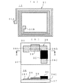
次に、図8に、本発明にかかる手荷物用RF−IDタグの使用例の説明図を示す。図8(A)に示す手荷物用RF−IDタグ11は、例えば空港での搭乗の際の託送荷物や乗船の際の託送荷物に取り付けられるバッゲージICタグとして上記のように作製されたものである。このような手荷物用RF−IDタグ11は、内包される転写RF−IDモジュール13に記憶された手荷物に関する情報のうち、一部または全部の、例えば行き先、便数、搭乗者番号等が感熱プリンタにより感熱シート12上に印字される。そして、当該手荷物用RF−IDタグ11より保護シート14の剥離部14A,14Bが切取ライン15A,15Bで分離されて剥離され、対象の手荷物の提げ手等にループ状とさせて粘着剤22同士を接着させて取り付けるものである。
【0044】
このような手荷物用RF−IDタグ11をバッゲージICタグとして使用することで、印字された手荷物情報で当該手荷物の所有者や行き先等を特定することができ、適宜ICモジュール32に記憶させたデータを読み込むことで当該手荷物の所有者や行き先等を特定することができるものである。
【0045】
そこで、図9に、本発明にかかる手荷物用RF−IDタグを使用するためのリーダライタのブロック構成図を示す。図9に示すリーダライタ61は、手荷物用RF−IDタグ(バッゲージICタグ)11の転写RF−IDモジュール13に対して手荷物に関する情報を記憶させ、少なくとも搬送途中に当該転写RF−IDモジュール13に記憶されている所定の情報を読み込むものである。また、リーダライタ61は、印字手段62および入力手段63と接続される。
【0046】
ここで、手荷物用RF−IDタグ(バッゲージICタグ)11は、処理部71、メモリ72および復調部73で構成されるICモジュール32が実装されたインターポーザ36と、アンテナ部31により構成される。アンテナ部31は、上述のように平面上でコイル状に巻回されたもので、リーダライタ61からの信号を受信し、または当該手荷物用RF−IDタグ(バッゲージICタグ)11よりリーダライタ61にデータを送信する役割をなす。
【0047】
上記インターポーザ36において、メモリ72は当該カードとしての種々の情報を記憶するためのものである。上記復調部73は、アンテナ部31で受信した電波から制御信号、データを復調し、適宜コード変換する。そして、処理部71は、プログラムにより、受信した制御信号、データをメモリ72に記憶させ、またメモリに記憶したデータを送信する処理を行う。
【0048】
リーダライタ61は、制御部81およびデータメモリ82を備え、データ変換部83、変調部84、発信部85、電力増幅部86、検波部87、アンテナ88、表示部89およびインターフェース(IF)部90を備える。上記制御部81は、このリーダライタ61の全体を統括制御するもので、これに応じたプログラムがセットされている。上記データメモリ83は、入力された託送荷物に関する種々のデータを記憶する。上記種々のデータには、例えば、荷物所有者の氏名、住所、電話番号、搭乗者番号、搭乗便名、行き先、座席番号等がある。
【0049】
上記データ変換部83は、当該手荷物用RF−IDタグ(バッゲージICタグ)11に対して情報を送信する場合の情報を例えば「1」、「0」に変換し、また当該手荷物用RF−IDタグ(バッゲージICタグ)11からの送信データを例えば「1」、「0」に変換する。上記変調部84は、発信部85からの発信出力に基づいて上記データ変換部83で変換された情報を例えばFSK(周波数偏位変調)変調波に変調する。上記電力増幅部86は、変調部84で変調された変調波を電力増幅するもので、この増幅された変調波がアンテナ88より送信されるものである。そして、検波部87は、アンテナ88で受信した当該手荷物用RF−IDタグ(バッゲージICタグ)11からの送信電波を検波して復調する。
【0050】
そして、表示部89は、適宜設けられるもので、取り扱うデータの表示を行う。また、IF部90は、印字部62に対して印字データを送信し、また入力手段63より入力データを取得する役割をなすものである。
【0051】
上記リーダライタ61は、例えば対象の手荷物用RF−IDタグ(バッゲージICタグ)11との通信と印字部62による印字とが同一ライン上で行うものとすると、まず、入力手段63より託送荷物に関する上記の荷物所有者の氏名、住所、電話番号、搭乗者番号、搭乗便名、行き先、座席番号等のデータが入力されることでデータメモリ82に記憶する。そして、当該記憶したデータのうち、所定のデータ(例えば搭乗者番号、搭乗便名、行き先)を手荷物用RF−IDタグ(バッゲージICタグ)11に送信してメモリ72に記憶させ、印字部62にも同様のデータを出力して当該手荷物用RF−IDタグ(バッゲージICタグ)11の感熱シート12部分に当該行き先、搭乗便名、搭乗者番号の印字を行わせるものである(図8参照)。
【0052】
このように、バッゲージICタグで使用される際に、剥離部14A,14Bによりループ状とさせるための粘着剤を表出させることにより、取り付け対象に当該粘着剤で付着することがなく、使用の際の利便性を向上させることができると共に、転写RF−IDモジュールが感熱シートと保護シートと間に介在されることにより、物理的、機械的ストレスに対して強度が増して耐久性を向上させることができる。また、このようなバッゲージICタグを、インターポーザ36を使用して作製することから、量産性の効率化、低コスト化を図ることができるものである。
【0053】
【発明の効果】
以上のように、本発明によれば、アンテナ部およびICモジュールを有する手荷物用RF−IDタグであって、剥離性の樹脂がコーティングされた剥離機能シートの平面上に導電性インキにより形成されたアンテナ部に実装される転写RF−IDモジュールが情報表示シートと保護シートとの間の何れかに転写によって介在され、長手方向の少なくとも一方端で剥離自在としてループ状とさせるための粘着剤を表出させることにより、当該粘着剤が付着することがなく、使用の際の利便性を向上させることができると共に、転写RF−IDモジュールが感熱シートと保護シートと間に介在されることにより、物理的、機械的ストレスに対して強度が増して耐久性を向上させることができる。
【0054】
また、少なくともアンテナ部を剥離機能シート上に形成し、転写シートに転写させることで作製することで製造工程における加熱や圧力印加の工程を剥離機能シート上で行わせることにより、使用される基材が加熱や圧力を考慮せずともよく、量産性、低コスト化を図ることができるものである。
【図面の簡単な説明】
【図1】本発明に係る手荷物用RF−IDタグの第1実施形態の構成図である。
【図2】図1の手荷物用RF−IDタグ製造の概念図である。
【図3】図1の手荷物用RF−IDタグ製造のフローチャートである。
【図4】図3の手荷物用RF−IDタグ製造における各段階の説明図(1)である。
【図5】図3の手荷物用RF−IDタグ製造における各段階の説明図(2)である。
【図6】本発明に係る手荷物用RF−IDタグの第2実施形態の構成図である。
【図7】図6のアンテナ部およびインターポーザの説明図である。
【図8】本発明にかかる手荷物用RF−IDタグの使用例の説明図である。
【図9】本発明にかかる手荷物用RF−IDタグを使用するためのリーダライタのブロック構成図である。
【符号の説明】
11 手荷物用RF−IDタグ
12 感熱シート
13 転写RF−IDモジュール
14 保護シート
15 切取ライン
16 剥離剤
21 感熱シート基材
22 粘着剤
23 感熱剤層
31 アンテナ部
32 ICモジュール
33,39 絶縁剤層
34 短絡ライン
35 ランド部
36 インターポーザ
37 インターポーザ基材
38 導電性パターン
41 RF−IDタグ製造システム
42 剥離機能シート
43,47 導電性インキ印刷手段
44,46,48 固化手段
45 絶縁性インキ印刷手段
49 ICモジュール実装手段
50 転写シート連続体供給部
51 保護シート連続体供給部
52 RF−IDタグ連続体収納部
61 リーダライタ[0001]
BACKGROUND OF THE INVENTION
The present invention relates to an RF-ID tag for baggage which is attached to a baggage to be sent and allows a baggage owner or the like to be identified in a non-contact manner and a manufacturing method thereof.
[0002]
[Prior art]
In recent years, a technology related to non-contact type IC media (non-contact type IC card, etc.) called RF-ID (Radio Frequency Identification) has been rapidly advanced. And an IC module (including a single IC bare chip) is mounted on both ends of the antenna. And the use is also various, and there is an RF-ID tag attached to the checked baggage. Such an RF-ID tag is required to be convenient for use, and mass production and cost reduction are desired in its manufacture, while it is required to have excellent durability depending on the use environment. .
[0003]
Conventionally, a baggage IC tag attached to a baggage that is sent when boarding at an airport or a baggage that is sent when boarding, for example, is adhered in a loop to a baggage hand. Most of such baggage IC tags are formed of a heat sensitive sheet, an RF-ID module, and a release paper. In this case, on the thermal tag paper, predetermined information at the time of consignment is printed by the thermal printer, and the owner and destination of the baggage are specified by the visual information and the electronic data stored in the tag. .
[0004]
For manufacturing the baggage IC tag as described above, a thermal tag paper having an adhesive applied on one side, a film on which an RF-ID module is formed, and a release paper having a release agent applied on the entire surface are prepared. Affix the film of the RF-ID module on the adhesive surface of the thermal tag paper, apply the adhesive to the surface, and make the release paper face the adhesive surface so that the release paper can be peeled off. Is.
[0005]
[Problems to be solved by the invention]
However, when the baggage IC tag as described above is peeled off the release paper and attached to a baggage, etc. in a loop shape, the entire surface from which the release paper is peeled becomes an adhesive surface. There is a problem in that it is not convenient to use because the adhesive may remain attached when the adhesive is attached to the litter or the like, or removed. Moreover, when producing the baggage IC tag, the film on which the RF-ID module is formed is expensive, and a step of attaching the film and a subsequent step of applying an adhesive are required, resulting in lack of mass productivity. There is a problem.
[0006]
Therefore, the present invention has been made in view of the above problems, and provides an RF-ID tag for baggage that improves convenience and durability during use, and is mass-productive and low in cost, and a method for manufacturing the tag. For the purpose.
[0007]
[Means for Solving the Problems]
In order to solve the above-mentioned problem, in the invention of
[0008]
According to a second aspect of the present invention, the information stored in the IC module and printed on the information display sheet is at least a part or all of information relating to the baggage.
[0009]
The invention of
[0010]
The invention of
[0011]
According to a fifth aspect of the present invention, the information stored in the IC module and printed on the information display sheet is at least a part or all of information relating to the baggage.
[0012]
Thus, an RF-ID tag for baggage having an antenna part and an IC module, on the plane of the release functional sheet coated with a peelable resin Mounted on the antenna part made of conductive ink The transfer RF-ID module is interposed between the information display sheet and the protective sheet by transfer, and exposes an adhesive for making it loopable at at least one end in the longitudinal direction. In other words, the adhesive for making the loop shape is exposed only at the part to be adhered, and the adhesive is not attached to the attachment target with the adhesive, and the convenience in use can be improved. In addition, the transfer RF-ID module can increase the strength against physical and mechanical stress by the heat-sensitive sheet and the protective sheet, thereby improving the durability.
[0013]
Furthermore, at least an antenna part is formed on a peeling functional sheet, and is produced by transferring it to a transfer sheet. That is, since the heating and pressure application steps in the manufacturing process are performed on the release function sheet, the substrate used does not need to consider heating and pressure, and mass productivity and cost reduction can be achieved. Become.
[0014]
DETAILED DESCRIPTION OF THE INVENTION
Hereinafter, preferred embodiments of the present invention will be described with reference to the drawings. FIG. 1 shows a configuration diagram of a first embodiment of an RF-ID tag for baggage according to the present invention. 1A is a longitudinal sectional view of an RF-ID tag for baggage, FIG. 1B is a configuration diagram of a transfer RF-ID module to be mounted, and FIG. 1C is a configuration diagram of a release sheet.
[0015]
The RF-
[0016]
The
[0017]
As shown in FIG. 1B, the transfer RF-
[0018]
That is, the
[0019]
The
[0020]
The IC module (internal structure is shown in FIG. 9) 32 is mounted between the land portion 31B and the
[0021]
On the other hand, bumps formed by metal electrolytic plating, studs, electroless metal plating, fixing of conductive resin, or the like are formed on the connection terminal portion of the
[0022]
FIG. 2 is a conceptual diagram for manufacturing the baggage RF-ID tag of FIG. FIG. 2 shows an RF-ID
[0023]
Above the conveyed release function sheet 42, in the order of conveyance, conductive ink printing means 43, solidifying means (here, heating) 44, insulating ink printing means 45, solidifying means (here, heating). ) 46, conductive ink printing means 47, and solidifying means (here, heating) 48 are disposed. The conductive ink printing means 43 is for forming the antenna pattern by printing with the conductive ink, and the solidifying
[0024]
The insulating ink printing means 45 is for forming the insulating layer 33 on the predetermined portion of the antenna pattern by printing with the insulating ink, and the solidifying means 46 forms the printed insulating layer 33. It is for heating and solidifying. Further, the conductive ink printing means 47 is for forming a short-circuit line 34 (land portion 35) on the insulating layer 33 by printing with the conductive ink, and the solidifying means 48 is a printed short-circuit. This is for heating and solidifying the line 34 (land portion 35).
[0025]
Further, an IC module mounting means 49 is disposed above the peeled functional sheet 42 to be conveyed and behind the solidifying means 48 in the conveying direction. The IC module mounting means 49 corresponds to the mounting method of the
[0026]
On the other hand, the continuous body of the heat sensitive sheet 12 coated with the pressure-
[0027]
Therefore, FIG. 3 shows a flowchart for manufacturing the RF-ID tag for baggage of FIG. 1, and FIGS. 4 and 5 are explanatory diagrams of each stage in manufacturing the RF-ID tag for baggage of FIG. 4 and 5 are shown as a single body or a part thereof. In FIG. 3, first, an antenna pattern (a part of the
[0028]
Subsequently, an insulating layer 33 constituting a part of the
[0029]
Subsequently, the RF-
[0030]
The RF-
[0031]
Further, at least the
[0032]
In the above embodiment, the
[0033]
On the other hand, when manufacturing the RF-
[0034]
Next, FIG. 6 shows a configuration diagram of a second embodiment of the RF-ID tag for baggage according to the present invention. 6A is a longitudinal sectional view of an RF-ID tag for baggage, FIG. 6B is a configuration diagram of a transfer RF-ID module to be mounted, and FIG. 6C is a configuration diagram of a release sheet. 6A and 6C is the same as that shown in FIGS. 1A and 1C. That is, the configuration of the transfer RF-
[0035]
FIG. 7 is an explanatory diagram of the antenna unit and the interposer shown in FIG. 7A, 7B, and 6B, the transfer RF-
[0036]
The antenna pattern is appropriately designed according to the IC module used and the usage pattern as an RF-ID tag, and the
[0037]
As shown in FIG. 7B, the
[0038]
As the
[0039]
The
[0040]
The
[0041]
On the other hand, the connection terminal portion of the
[0042]
Here, the manufacture of the
[0043]
Next, FIG. 8 shows an explanatory diagram of an example of use of the RF-ID tag for baggage according to the present invention. The baggage RF-
[0044]
By using such an RF-
[0045]
FIG. 9 is a block diagram of a reader / writer for using the baggage RF-ID tag according to the present invention. The reader / writer 61 shown in FIG. 9 stores information on baggage in the transfer RF-
[0046]
The baggage RF-ID tag (baggage IC tag) 11 includes an
[0047]
In the
[0048]
The reader / writer 61 includes a control unit 81 and a data memory 82, and includes a data conversion unit 83, a modulation unit 84, a transmission unit 85, a power amplification unit 86, a detection unit 87, an antenna 88, a
[0049]
The data conversion unit 83 converts information when transmitting information to the baggage RF-ID tag (baggage IC tag) 11 into, for example, “1” and “0”, and the baggage RF-ID. Transmission data from the tag (baggage IC tag) 11 is converted into, for example, “1” and “0”. The modulation unit 84 modulates the information converted by the data conversion unit 83 based on the transmission output from the transmission unit 85, for example, into an FSK (frequency shift keying) modulated wave. The power amplifying unit 86 amplifies the power of the modulated wave modulated by the modulating unit 84, and the amplified modulated wave is transmitted from the antenna 88. Then, the detector 87 detects and demodulates the transmission radio wave received from the RF-ID tag (baggage IC tag) 11 for the baggage received by the antenna 88.
[0050]
And the
[0051]
For example, when the reader / writer 61 performs communication with the RF-ID tag (baggage IC tag) 11 for the target baggage and printing by the printing unit 62 on the same line, the reader / writer 61 first relates to the consignment baggage from the input unit 63. Data such as the name, address, telephone number, passenger number, boarding flight name, destination, seat number, etc. of the above-mentioned luggage owner are inputted and stored in the data memory 82. Among the stored data, predetermined data (for example, passenger number, boarding flight name, destination) is transmitted to the RF-ID tag (baggage IC tag) 11 for baggage, stored in the memory 72, and printed. The same data is also output to print the destination, boarding flight name, and passenger number on the thermal sheet 12 portion of the baggage RF-ID tag (baggage IC tag) 11 (see FIG. 8). ).
[0052]
As described above, when the adhesive is used for the baggage IC tag, the adhesive for making the loop shape is exposed by the peeling portions 14A and 14B, so that the adhesive is not attached to the attachment target. In addition, the transfer RF-ID module is interposed between the heat-sensitive sheet and the protective sheet, thereby increasing the strength against physical and mechanical stress and improving the durability. be able to. Further, since such a baggage IC tag is manufactured using the
[0053]
【The invention's effect】
As described above, according to the present invention, an RF-ID tag for baggage having an antenna unit and an IC module, on the plane of a release functional sheet coated with a release resin. Mounted on the antenna part made of conductive ink The transfer RF-ID module is interposed between the information display sheet and the protective sheet by transfer, and exposes an adhesive for making it loopable at least at one end in the longitudinal direction. Adhesive is not attached and the convenience in use can be improved, and the transfer RF-ID module is interposed between the heat-sensitive sheet and the protective sheet, so that physical and mechanical stress can be prevented. On the other hand, the strength can be increased and the durability can be improved.
[0054]
In addition, by forming at least the antenna portion on the release function sheet and transferring it to the transfer sheet, the substrate used can be used by performing the heating and pressure application steps in the manufacturing process on the release function sheet. However, it is not necessary to consider heating and pressure, and mass production and cost reduction can be achieved.
[Brief description of the drawings]
FIG. 1 is a configuration diagram of a first embodiment of an RF-ID tag for baggage according to the present invention.
FIG. 2 is a conceptual diagram of manufacturing the RF-ID tag for baggage of FIG.
FIG. 3 is a flowchart for manufacturing the RF-ID tag for baggage of FIG. 1;
FIG. 4 is an explanatory diagram (1) of each stage in manufacturing the baggage RF-ID tag of FIG. 3;
FIG. 5 is an explanatory diagram (2) of each stage in the manufacture of the RF-ID tag for baggage of FIG.
FIG. 6 is a configuration diagram of a second embodiment of an RF-ID tag for baggage according to the present invention.
7 is an explanatory diagram of an antenna unit and an interposer in FIG. 6. FIG.
FIG. 8 is an explanatory diagram of a usage example of an RF-ID tag for baggage according to the present invention.
FIG. 9 is a block diagram of a reader / writer for using the baggage RF-ID tag according to the present invention.
[Explanation of symbols]
11 RF-ID tag for baggage
12 Thermal sheet
13 Transfer RF-ID module
14 Protection sheet
15 Cut line
16 Release agent
21 Thermal sheet base material
22 Adhesive
23 Heat-sensitive agent layer
31 Antenna section
32 IC module
33,39 Insulating agent layer
34 Short circuit line
35 Land
36 Interposer
37 Interposer base material
38 Conductive pattern
41 RF-ID tag manufacturing system
42 Peeling function sheet
43, 47 Conductive ink printing means
44, 46, 48 Solidification means
45 Insulating ink printing means
49 IC module mounting means
50 Transfer sheet continuum supply unit
51 Continuous protective sheet supply unit
52 RF-ID tag continuous body storage
61 Reader / Writer
Claims (5)
前記ICモジュールに記憶された情報と関連する情報が所定の印字手段により印字される情報表示シートと、
前記情報表示シートと粘着剤により積層されるもので、長手方向の両端の少なくとも一方に、前記ループ状とさせる前記粘着剤を表出させるための剥離剤が形成され、当該剥離剤部分が剥離自在な保護シートと、
前記情報表示シートと前記保護シートとの間に介在され、剥離性の樹脂がコーティングされた剥離機能シートの平面上に導電性インキにより形成した前記アンテナ部に前記ICモジュール若しくはICモジュールユニットを実装させて前記情報表示シート若しくは前記保護シート上に粘着剤で転写させることにより前記RF−ICモジュールを構成させ、または、剥離性の樹脂がコーティングされた剥離機能シートの平面上に導電性インキにより形成した前記アンテナ部を前記情報表示シート若しくは前記保護シート上に粘着剤で転写させて前記ICモジュール若しくはICモジュールユニットを実装させることにより前記RF−IDモジュールを構成させる転写RF−IDモジュールと、
を有することを特徴とする手荷物用RF−IDタグ。An IC module, or a baggage that is provided with an RF-ID module in which an IC module unit mounted on a base material on which a connection land portion is formed is mounted on an antenna, is looped and attached to the baggage RF-ID tag for use,
An information display sheet on which information related to the information stored in the IC module is printed by a predetermined printing means;
It is laminated with the information display sheet and an adhesive, and a release agent is formed on at least one of both ends in the longitudinal direction to expose the adhesive to be looped, and the release agent part can be peeled freely. Protective sheet,
The IC module or the IC module unit is mounted on the antenna portion that is interposed between the information display sheet and the protective sheet and is formed of a conductive ink on a plane of a release function sheet coated with a release resin. The RF-IC module is configured by transferring it with an adhesive onto the information display sheet or the protective sheet, or formed with a conductive ink on the plane of a release functional sheet coated with a release resin. A transfer RF-ID module that constitutes the RF-ID module by transferring the antenna unit onto the information display sheet or the protective sheet with an adhesive and mounting the IC module or IC module unit;
An RF-ID tag for baggage, comprising:
被形成物が剥離自在な剥離性の樹脂がコーティングされた剥離機能シートの平面上に、導電性インキにより前記アンテナ部が形成される工程と、
前記アンテナ部に前記ICモジュールまたはICモジュールユニットが実装されることで前記RF−IDモジュールが形成される工程と、
前記情報表示シート、または長手方向の両端の少なくとも一方に前記ループ状とさせる粘着剤を表出させるための剥離剤が形成されて当該剥離剤部分が剥離自在とされる保護シートで構成される転写シートに、前記RF−IDモジュールを粘着剤により接着させることで前記剥離機能シートより剥離させて転写させる工程と、
前記転写シートにおける転写された前記RF−IDモジュール側に、当該転写シートが前記情報表示シートの場合には前記保護シートを、当該転写シートが前記保護シートの場合には前記情報表示シートを接着させる工程と、
を含むことを特徴とする手荷物用RF−IDタグの製造方法。An IC module, or a baggage that is provided with an RF-ID module in which an IC module unit mounted on a base material on which a connection land portion is formed is mounted on an antenna, is looped and attached to the baggage A method of manufacturing an RF-ID tag for use,
On the plane of the release functional sheet coated with a releasable resin from which the object can be peeled, the step of forming the antenna portion with conductive ink;
A step of forming the RF-ID module by mounting the IC module or the IC module unit on the antenna unit;
Transfer composed of the information display sheet or a protective sheet on which at least one of both ends in the longitudinal direction is formed with a release agent for exposing the adhesive to be formed into the loop shape, and the release agent part can be peeled off. A step of causing the sheet to be peeled off and transferred from the peeling function sheet by bonding the RF-ID module with an adhesive;
When the transfer sheet is the information display sheet, the protective sheet is attached to the transferred RF-ID module side of the transfer sheet, and when the transfer sheet is the protection sheet, the information display sheet is attached. Process,
A method for manufacturing an RF-ID tag for baggage, comprising:
被形成物が剥離自在な剥離性の樹脂がコーティングされた剥離機能シートの平面上に、導電性インキにより前記アンテナ部が形成される工程と、
前記情報表示シート、または長手方向の両端の少なくとも一方に前記ループ状とさせる粘着剤を表出させるための剥離剤が形成されて当該剥離剤部分が剥離自在とされる保護シートで構成される転写シートに、前記アンテナ部を粘着剤により接着させることで前記剥離機能シートより剥離させて転写させる工程と、
前記転写シート上で、転写された前記アンテナ部に前記ICモジュールまたはICモジュールユニットが実装されることで前記RF−IDモジュールが形成される工程と、
前記転写シートにおける転写された前記RF−IDモジュール側に、当該転写シートが前記情報表示シートの場合には前記保護シートを、当該転写シートが前記保護シートの場合には前記情報表示シートを接着させる工程と、
を含むことを特徴とする手荷物用RF−IDタグの製造方法。An IC module, or a baggage that is provided with an RF-ID module in which an IC module unit mounted on a base material on which a connection land portion is formed is mounted on an antenna, is looped and attached to the baggage A method of manufacturing an RF-ID tag for use,
On the plane of the release functional sheet coated with a releasable resin from which the object can be peeled, the step of forming the antenna portion with conductive ink;
Transfer composed of the information display sheet or a protective sheet on which at least one of both ends in the longitudinal direction is formed with a release agent for exposing the adhesive to be formed into the loop shape, and the release agent part can be peeled off. A step of separating and transferring from the release functional sheet by bonding the antenna part to the sheet with an adhesive, and
On the transfer sheet, the RF-ID module is formed by mounting the IC module or IC module unit on the transferred antenna portion;
When the transfer sheet is the information display sheet, the protective sheet is attached to the transferred RF-ID module side of the transfer sheet, and when the transfer sheet is the protection sheet, the information display sheet is attached. Process,
A method for manufacturing an RF-ID tag for baggage, comprising:
Priority Applications (1)
| Application Number | Priority Date | Filing Date | Title |
|---|---|---|---|
| JP2002089089A JP3906331B2 (en) | 2002-03-27 | 2002-03-27 | RF-ID tag for baggage and manufacturing method thereof |
Applications Claiming Priority (1)
| Application Number | Priority Date | Filing Date | Title |
|---|---|---|---|
| JP2002089089A JP3906331B2 (en) | 2002-03-27 | 2002-03-27 | RF-ID tag for baggage and manufacturing method thereof |
Publications (2)
| Publication Number | Publication Date |
|---|---|
| JP2003288572A JP2003288572A (en) | 2003-10-10 |
| JP3906331B2 true JP3906331B2 (en) | 2007-04-18 |
Family
ID=29234772
Family Applications (1)
| Application Number | Title | Priority Date | Filing Date |
|---|---|---|---|
| JP2002089089A Expired - Fee Related JP3906331B2 (en) | 2002-03-27 | 2002-03-27 | RF-ID tag for baggage and manufacturing method thereof |
Country Status (1)
| Country | Link |
|---|---|
| JP (1) | JP3906331B2 (en) |
Families Citing this family (6)
| Publication number | Priority date | Publication date | Assignee | Title |
|---|---|---|---|---|
| JP2006131331A (en) * | 2004-11-05 | 2006-05-25 | Brother Ind Ltd | Tag tape roll, and radio tag circuit element cartridge |
| WO2006049107A1 (en) | 2004-11-05 | 2006-05-11 | Brother Kogyo Kabushiki Kaisha | Tag tape roll, tag tape, and wireless tag circuit element cartridge |
| CN100361150C (en) * | 2005-06-24 | 2008-01-09 | 清华大学 | Radio frequency identification marking card with silicon base integrated antenna |
| JP5050663B2 (en) * | 2007-05-31 | 2012-10-17 | 大日本印刷株式会社 | RFID tag for baggage |
| JP5018309B2 (en) * | 2007-07-23 | 2012-09-05 | 大日本印刷株式会社 | IC tag |
| JP5142867B2 (en) * | 2008-07-17 | 2013-02-13 | トッパン・フォームズ株式会社 | RFID label sheet and RFID label |
-
2002
- 2002-03-27 JP JP2002089089A patent/JP3906331B2/en not_active Expired - Fee Related
Also Published As
| Publication number | Publication date |
|---|---|
| JP2003288572A (en) | 2003-10-10 |
Similar Documents
| Publication | Publication Date | Title |
|---|---|---|
| US8162231B2 (en) | Noncontact IC tag label and method of manufacturing the same | |
| US20050046573A1 (en) | Selective metal removal process for metallized retro-reflective and holographic films and radio frequency devices made therewith | |
| JP2002298109A (en) | Contactless ic medium and manufacturing method thereof | |
| JP2005011330A (en) | Information carrier, information recording medium, sensor and article managment method | |
| US20010008684A1 (en) | Information recording tag | |
| WO2008056564A1 (en) | Non-contact ic tag label, airline luggage tag label, and method for producing non-contact ic tag label | |
| US20060290512A1 (en) | Methods and apparatus for RFID transponder fabrication | |
| JP3854124B2 (en) | Non-contact IC label | |
| JP3906331B2 (en) | RF-ID tag for baggage and manufacturing method thereof | |
| JP5088544B2 (en) | Manufacturing method of wireless IC device | |
| JP2000105807A (en) | Label type noncontact data carrier | |
| JP3839337B2 (en) | Non-contact type IC media and manufacturing method thereof | |
| JP4675184B2 (en) | IC tag | |
| WO2008063785A9 (en) | Radio frequency identification (rfid) tag lamination process | |
| JP2000105806A (en) | Label type noncontact data carrier | |
| JP2002352199A (en) | Wrist-worn type antenna for rfid tag communication | |
| JP3897160B2 (en) | Non-contact type IC media and manufacturing method thereof | |
| JP2003332714A (en) | Media equipped with conductive circuit and method of manufacturing same | |
| JP4526195B2 (en) | Baggage tag and its manufacturing method | |
| JP2004005260A (en) | Ic medium having electroluminescent display part and its manufacturing method | |
| JP2015060504A (en) | Non-contact ic label | |
| JP2004220413A (en) | Rfid inlet and device for working the same | |
| JP4693295B2 (en) | Circuit formation method | |
| JP2003006594A (en) | Formation method for rf-id medium using both-side tape | |
| JP2015210704A (en) | Ic tag built-in print sheet |
Legal Events
| Date | Code | Title | Description |
|---|---|---|---|
| A621 | Written request for application examination |
Free format text: JAPANESE INTERMEDIATE CODE: A621 Effective date: 20040527 |
|
| A977 | Report on retrieval |
Free format text: JAPANESE INTERMEDIATE CODE: A971007 Effective date: 20060208 |
|
| A131 | Notification of reasons for refusal |
Free format text: JAPANESE INTERMEDIATE CODE: A131 Effective date: 20060228 |
|
| A521 | Written amendment |
Free format text: JAPANESE INTERMEDIATE CODE: A523 Effective date: 20060412 |
|
| A131 | Notification of reasons for refusal |
Free format text: JAPANESE INTERMEDIATE CODE: A131 Effective date: 20060725 |
|
| A521 | Written amendment |
Free format text: JAPANESE INTERMEDIATE CODE: A523 Effective date: 20060905 |
|
| TRDD | Decision of grant or rejection written | ||
| A01 | Written decision to grant a patent or to grant a registration (utility model) |
Free format text: JAPANESE INTERMEDIATE CODE: A01 Effective date: 20061212 |
|
| A61 | First payment of annual fees (during grant procedure) |
Free format text: JAPANESE INTERMEDIATE CODE: A61 Effective date: 20061213 |
|
| R150 | Certificate of patent or registration of utility model |
Free format text: JAPANESE INTERMEDIATE CODE: R150 |
|
| FPAY | Renewal fee payment (event date is renewal date of database) |
Free format text: PAYMENT UNTIL: 20100126 Year of fee payment: 3 |
|
| FPAY | Renewal fee payment (event date is renewal date of database) |
Free format text: PAYMENT UNTIL: 20110126 Year of fee payment: 4 |
|
| FPAY | Renewal fee payment (event date is renewal date of database) |
Free format text: PAYMENT UNTIL: 20120126 Year of fee payment: 5 |
|
| FPAY | Renewal fee payment (event date is renewal date of database) |
Free format text: PAYMENT UNTIL: 20130126 Year of fee payment: 6 |
|
| FPAY | Renewal fee payment (event date is renewal date of database) |
Free format text: PAYMENT UNTIL: 20130126 Year of fee payment: 6 |
|
| FPAY | Renewal fee payment (event date is renewal date of database) |
Free format text: PAYMENT UNTIL: 20140126 Year of fee payment: 7 |
|
| R250 | Receipt of annual fees |
Free format text: JAPANESE INTERMEDIATE CODE: R250 |
|
| R250 | Receipt of annual fees |
Free format text: JAPANESE INTERMEDIATE CODE: R250 |
|
| R250 | Receipt of annual fees |
Free format text: JAPANESE INTERMEDIATE CODE: R250 |
|
| LAPS | Cancellation because of no payment of annual fees |