JP3887810B2 - Game device - Google Patents
Game device Download PDFInfo
- Publication number
- JP3887810B2 JP3887810B2 JP25667198A JP25667198A JP3887810B2 JP 3887810 B2 JP3887810 B2 JP 3887810B2 JP 25667198 A JP25667198 A JP 25667198A JP 25667198 A JP25667198 A JP 25667198A JP 3887810 B2 JP3887810 B2 JP 3887810B2
- Authority
- JP
- Japan
- Prior art keywords
- game
- display
- screen
- display magnification
- image
- Prior art date
- Legal status (The legal status is an assumption and is not a legal conclusion. Google has not performed a legal analysis and makes no representation as to the accuracy of the status listed.)
- Expired - Lifetime
Links
Images


Classifications
-
- A—HUMAN NECESSITIES
- A63—SPORTS; GAMES; AMUSEMENTS
- A63F—CARD, BOARD, OR ROULETTE GAMES; INDOOR GAMES USING SMALL MOVING PLAYING BODIES; VIDEO GAMES; GAMES NOT OTHERWISE PROVIDED FOR
- A63F2300/00—Features of games using an electronically generated display having two or more dimensions, e.g. on a television screen, showing representations related to the game
- A63F2300/30—Features of games using an electronically generated display having two or more dimensions, e.g. on a television screen, showing representations related to the game characterized by output arrangements for receiving control signals generated by the game device
- A63F2300/303—Features of games using an electronically generated display having two or more dimensions, e.g. on a television screen, showing representations related to the game characterized by output arrangements for receiving control signals generated by the game device for displaying additional data, e.g. simulating a Head Up Display
- A63F2300/307—Features of games using an electronically generated display having two or more dimensions, e.g. on a television screen, showing representations related to the game characterized by output arrangements for receiving control signals generated by the game device for displaying additional data, e.g. simulating a Head Up Display for displaying an additional window with a view from the top of the game field, e.g. radar screen
-
- A—HUMAN NECESSITIES
- A63—SPORTS; GAMES; AMUSEMENTS
- A63F—CARD, BOARD, OR ROULETTE GAMES; INDOOR GAMES USING SMALL MOVING PLAYING BODIES; VIDEO GAMES; GAMES NOT OTHERWISE PROVIDED FOR
- A63F2300/00—Features of games using an electronically generated display having two or more dimensions, e.g. on a television screen, showing representations related to the game
- A63F2300/60—Methods for processing data by generating or executing the game program
- A63F2300/66—Methods for processing data by generating or executing the game program for rendering three dimensional images
- A63F2300/6661—Methods for processing data by generating or executing the game program for rendering three dimensional images for changing the position of the virtual camera
- A63F2300/6669—Methods for processing data by generating or executing the game program for rendering three dimensional images for changing the position of the virtual camera using a plurality of virtual cameras concurrently or sequentially, e.g. automatically switching between fixed virtual cameras when a character change rooms
-
- A—HUMAN NECESSITIES
- A63—SPORTS; GAMES; AMUSEMENTS
- A63F—CARD, BOARD, OR ROULETTE GAMES; INDOOR GAMES USING SMALL MOVING PLAYING BODIES; VIDEO GAMES; GAMES NOT OTHERWISE PROVIDED FOR
- A63F2300/00—Features of games using an electronically generated display having two or more dimensions, e.g. on a television screen, showing representations related to the game
- A63F2300/60—Methods for processing data by generating or executing the game program
- A63F2300/66—Methods for processing data by generating or executing the game program for rendering three dimensional images
- A63F2300/6661—Methods for processing data by generating or executing the game program for rendering three dimensional images for changing the position of the virtual camera
- A63F2300/6676—Methods for processing data by generating or executing the game program for rendering three dimensional images for changing the position of the virtual camera by dedicated player input
-
- A—HUMAN NECESSITIES
- A63—SPORTS; GAMES; AMUSEMENTS
- A63F—CARD, BOARD, OR ROULETTE GAMES; INDOOR GAMES USING SMALL MOVING PLAYING BODIES; VIDEO GAMES; GAMES NOT OTHERWISE PROVIDED FOR
- A63F2300/00—Features of games using an electronically generated display having two or more dimensions, e.g. on a television screen, showing representations related to the game
- A63F2300/60—Methods for processing data by generating or executing the game program
- A63F2300/66—Methods for processing data by generating or executing the game program for rendering three dimensional images
- A63F2300/6661—Methods for processing data by generating or executing the game program for rendering three dimensional images for changing the position of the virtual camera
- A63F2300/6684—Methods for processing data by generating or executing the game program for rendering three dimensional images for changing the position of the virtual camera by dynamically adapting its position to keep a game object in its viewing frustrum, e.g. for tracking a character or a ball
-
- A—HUMAN NECESSITIES
- A63—SPORTS; GAMES; AMUSEMENTS
- A63F—CARD, BOARD, OR ROULETTE GAMES; INDOOR GAMES USING SMALL MOVING PLAYING BODIES; VIDEO GAMES; GAMES NOT OTHERWISE PROVIDED FOR
- A63F2300/00—Features of games using an electronically generated display having two or more dimensions, e.g. on a television screen, showing representations related to the game
- A63F2300/80—Features of games using an electronically generated display having two or more dimensions, e.g. on a television screen, showing representations related to the game specially adapted for executing a specific type of game
- A63F2300/8017—Driving on land or water; Flying
Description
【0001】
【産業上の利用分野】
本発明はゲーム装置に係り、仮想空間上に、例えば、車等を模したオブジェクトを配置し、当該オブジェクトを遊技者からの操作に応答して移動させた様子をディスプレイに表示してゲームをさせるプログラムを搭載したゲーム装置に関する。
【0002】
【従来の技術】
ゲーム装置は、コンピュータ技術の発達に伴い、家庭用あるいは業務用を問わず、より鮮明で、よりリアルな画像のものが求められている。ゲーム装置は、一般に、予め記憶したゲームプログラムを実行するコンピュータ装置を内蔵したゲーム装置本体と、ゲームで表現させるオブジェクトの移動やその他の指令を与えるための操作信号をコンピュータ装置に与える操作機と、コンピュータ装置でゲームプログラムが実行されることによるゲーム展開(game proceeding)に伴う画像を表示するディスプレイと、そのゲーム展開に伴う音響を発生させる音響装置とを備えている。
【0003】
このような構成のゲーム装置の一分野としてドライビングゲーム(オートレースゲーム)を扱うゲーム装置がある。
【0004】
また、仮想空間内を遊技者からの操作信号に基づいて、オブジェクトを自由に移動させながら、対戦格闘ゲームを進行させるものもある。
【0005】
このようなゲームでは、仮想空間内での遊技者の操作するオブジェクトや敵の位置を示したり、周囲の状況を、遊技者に分り易く示すために、ゲーム画面上に簡略化された地図や、敵・味方等のオブジェクトの配置を示すいわゆるレーダー画面等の補助情報画面が表示されている。
【0006】
【発明が解決しようとする課題】
しかしながら、遊技者の操作するオブジェクト(以下、自機という)の周囲を遠方まで見せるような補助情報画面を、ゲーム画面に重畳して表示した場合は、仮想空間の広い範囲を縮小表示することになる。すると、自機と自機の周囲の情報が相対的に小さく表示され、詳細な情報を得ることが難しい。
【0007】
上記の点に鑑み、詳細な周囲の補助情報を提供するために、オブジェクトの近傍のみを表示しようとした場合には、次に展開されるであろう状況(例えば、遠方に配置されていた、他の遊技者やコンピュータプログラムによって制御されるオブジェクト(以下、他機)が自機に向って突進している等)を把握しにくいので、高速での自機の移動やゲーム展開の予測が困難になるという問題があった。
【0008】
一方、レースコースを進行してゴールを目指し、かつ、他機との攻防をしながら、ゲームを展開するようなゲームの場合は、他機と自機との相対位置をより効果的に把握できるようにすべきである。また、必要に応じて、ゲームのその後の展開、例えば、レースコースをも、遊戯者が把握し易いようにすべきである。
【0009】
よって、本発明の第1の目的は、ゲーム画面中に、次に展開されるコースの詳しい形状を知ることができる補助画面を表示するゲーム装置を 提供する ことである。
【0010】
また、本発明の第2の目的は、自機と他機との相対的位置を把握し易いように表示する補助画面を備えるゲーム装置を提供することである。
【0011】
また、本発明の第3の目的は、自機の後方に存在する他機に関する情報を表示するようにしたゲーム装置を提供することである。
【0012】
【課題を解決するための手段】
上記目的を達成するため本発明のゲーム装置は、遊技者によって制御される第1のオブジェクトと、コンピュータ若しくは対戦者によって制御される第2のオブジェクトとが、仮想空間内で展開するゲームの様子をモニタ画面に表示するゲーム装置において、上記第1のオブジェクトの制御を支援する情報を表示(あるいは図示)する小画面を上記モニタ画面中に形成する支援画面形成手段(S210)と、上記仮想空間におけるゲームの展開において上記小画面の表示倍率を変更すべき所定の条件に該当するかどうかを判別する表示モード変更判別手段(S206)と、上記判別結果に基づいて上記小画面の表示倍率を設定する表示倍率設定手段(S208)と、を備える。
【0013】
例えば、上記所定の条件は、上記第1及び第2のオブジェクト相互間の離間距離が基準値を越えたかどうかである。
【0014】
例えば、上記所定の条件は、上記第1のオブジェクトの移動速度が基準値を越えたかどうかである。
【0015】
例えば、上記所定の条件は、上記第1のオブジェクトが上記仮想空間内の予め定められた場所に移動するかどうかである。
【0016】
例えば、上記所定の条件は、上記仮想空間内に予め定められたイベントが発生したかどうかである。
【0017】
本発明のゲーム装置は、遊技者によって制御される第1のオブジェクトと、コンピュータ若しくは対戦者によって制御される第2のオブジェクトと、が仮想空間内で展開するゲームの様子をモニタ画面に表示するゲーム装置において、上記第1のオブジェクトを中心とする周囲の状況を表す小画面を前記モニタ画面中に形成する支援画面形成手段(S210)と、上記仮想空間における第1のオブジェクトと第2のオブジェクトとの離間距離を計算する距離計算手段(S202)と、上記小画面について予め定められたの複数の表示倍率から前記離間距離に対応した表示倍率を設定する表示倍率設定手段(S208)と、上記設定に際し、上記表示倍率を現在値から増加する場合と減少する場合とで、上記離間距離と上記表示倍率との対応付けを異ならしめて上記表示倍率の設定に履歴動作を行わせる履歴動作手段(S208、図10)と、を備える。
【0018】
好ましくは、上記表示倍率設定手段は、上記表示倍率の設定に際し、上記表示倍率を現在値から設定すべき表示倍率に徐々に移行する(図11)。
【0019】
例えば、上記小画面にはコース図が含まれ、上記表示倍率設定手段は、上記離間距離に応じて前記コース図の縮尺を設定する(図7〜図9)。
【0020】
例えば、上記第2のオブジェクトは複数存在し、上記距離計算手段は、上記第1のオブジェクトと上記複数の第2のオブジェクト各々との各離間距離を計算し、そのうち最も最短の離間距離を出力する。
【0021】
かかる構成とすることによって、近くに第2のオブジェクトである他機(あるいは自車)が存在しないときは、小画面の表示縮尺(あるいは表示倍率)が大きく設定されるので、プレイヤが第1のオブジェクトである自機(あるいは自車)と上記他車との相対位置関係を把握し易いようになる。また、近くに他車がいないときは、小画面の表示縮尺が小に設定されるので、プレイヤがレースのコース形状を広範囲に見ることができるようになる。これは、闘いを行いながらレースを展開するゲームに好適なゲーム支援画面である。また、画面の切替が頻繁に起ることを回避可能である。
【0022】
本発明のゲーム装置は、遊技者によって制御される第1のオブジェクトと、コンピュータ若しくは対戦者によって制御される第2のオブジェクトと、が仮想空間内で展開するゲームの様子をモニタの画面に表示するゲーム装置において、上記仮想空間における第1のオブジェクト若しくは仮想カメラと、第1のオブジェクトの後方に位置する第2のオブジェクトとの離間距離を計算する距離計算手段(S306)と、上記第2のオブジェクトを上記離間距離に応じた大きさのシンボルで上記モニタの画面中に表示する後方オブジェクトのシンボル形成手段(S306)と、を備える。
【0023】
かかる構成とすることによって、ゲーム中の画面に表示されない、後方から接近してくる第2のオブジェクトである他機(あるいは他車)についてプレイヤの注意を喚起することが可能となる。
【0024】
本発明のゲーム装置は、遊技者によって制御される第1のオブジェクトと、コンピュータ若しくは対戦者によって制御される第2のオブジェクトとが、仮想空間内で展開するゲームの様子を仮想カメラによってモニタし、これをモニタの画面に表示するゲーム装置において、上記仮想カメラの位置を、上記第1のオブジェクトの前方をこのオブジェクトの位置又はこのオブジェクトの近傍の位置から見せる第1の位置と、上記第1のオブジェクトの後方から上記前方を見せる第2の位置とに切替える切替指令を発するカメラ位置切替指令手段(22)と、上記第1のオブジェクトの後方に上記第2のオブジェクトが存在するとき(S404)、上記仮想カメラの位置を上記第1の位置に切替える切替指令に対応して(S402)、上記第2のオブジェクトを表すシンボルを上記モニタの画面中に表示するシンボル表示手段(S406)と、を備える。
【0025】
また、本発明のゲーム装置は、遊技者によって制御される第1のオブジェクトと、コンピュータ若しくは対戦者によって制御される第2のオブジェクトとが、仮想空間内で展開するゲームの様子を仮想カメラによってモニタし、これをモニタの画面に表示するゲーム装置において、上記仮想カメラの位置を、上記第1のオブジェクトの前方を表示しかつその後方を表示しない第1の位置と、上記第1のオブジェクトの後方から上記前方を見せる第2の位置とに切替える切替指令を発するカメラ位置切替指令手段(22)と、上記第1のオブジェクトの後方に上記第2のオブジェクトが存在するとき(S404)、上記仮想カメラの位置を上記第1の位置に切替える切替指令に対応して(S402)、上記第2のオブジェクトを表すシンボルを上記モニタ画面中に表示するシンボル表示手段(S406)とを備える。
【0026】
好ましくは、上記シンボル表示手段は、上記仮想空間における上記第1のオブジェクト若しくは上記仮想カメラと、上記第1のオブジェクトの後方に存在する上記第2のオブジェクトと、の離間距離を計算する距離計算手段(S406)と、上記後方の第2のオブジェクトを上記離間距離に応じた大きさのシンボルで上記モニタ画面中に表示させるシンボル形成手段(S406)と、を含む。
【0027】
好ましくは、上記シンボル形成手段は、更に、上記シンボルの上記モニタ画面中の表示位置を上記後方の第2のオブジェクトの上記仮想空間内における位置に対応して定める。
【0028】
かかる構成とすることによって、カメラ視点を切替えることによってゲーム画面に見えなくなった後方のオブジェクトの情報を適宜にゲーム画面中に表示することが可能となる。
【0029】
本発明のゲーム装置の画像表示方法は、遊技者によって制御される第1のオブジェクトと、コンピュータ若しくは対戦者によって制御される第2のオブジェクトとが、仮想空間内で展開するゲームの様子をモニタ画面に表示するゲーム装置における画像表示方法において、上記仮想空間における上記第1のオブジェクトの周囲の様子を表示した小画面を上記モニタ画面中に形成する小画面形成過程(S210)と、上記仮想空間におけるゲームの展開において、上記小画面の表示を拡大表示叉は縮小表示とすべき条件に該当するかどうかを判別する判別過程(S206)と、上記条件に該当するときに、上記小画面の表示を拡大表示叉は縮小表示に変更する表示変更過程(S208)と、を含む。
【0030】
かかる構成とすることにより、ゲーム展開中に所定の条件に対応して、小画面に表示される内容が拡大あるいは縮小された適当な表示倍率(あるいは縮尺)で表示される。このため、表示面積の小さい小画面を全体的表示や部分的な表示として必要な情報を効果的に示すことが可能となる。
【0031】
好ましくは、上記所定の条件は、(a)上記第1及び第2のオブジェクト相互間の離間距離が基準値を越えること、(b)上記第1のオブジェクトの移動速度が基準値を越えること、 (c)上記第1のオブジェクトが上記仮想空間内の予め定められた場所に移動すること、(d)上記仮想空間内に予め定められたイベントが発生したかどうかであること、のうち少なくともいずれかである。
【0032】
好ましくは、上記表示変更過程は、更に、上記小画面の表示倍率を徐々に変えることによって、上記小画面全体の大きさを変えずに、上記小画面に表示される上記第1のオブジェクトを含む領域の外囲を緩やかに拡大叉は縮小する。
【0033】
好ましくは、上記小画面形成過程は、更に、ゲームのコース地図上に上記第1及び第2のオブジェクトをシンボルで表示し、上記表示変更過程は、更に、上記第1及び第2のオブジェクト相互間の離間距離に応じて上記コース地図の縮尺を設定する。
【0034】
本発明に係る情報記録媒体は、コンピュータシステムを上述したゲーム装置として機能させるコンピュータプログラムを記録している。
【0035】
また、本発明に係る情報記録媒体は、コンピュータシステムに上述した画像表示方法を方法を実行させるプログラムを記録している。
【0036】
【発明の実施の形態】
以下、本発明の実施の形態について図面を参照して説明する。図1は、本発明に係る、ドライビングゲーム用ゲーム装置の実施の形態の例を示す斜視図である。図2は、同オートバイ形状をした操作機のハンドル回りの平面図である。
【0037】
本願発明の実施の形態が適用されたゲーム装置1は、図に示すように、主に操作信号を形成しかつキックバック動作もするオートバイ形状に類似の操作機(以下、「オートバイ型操作機」という)2と、このオートバイ型操作機2の前面に設けたゲーム機本体3とから構成されている。このゲーム機本体3は、所定の大きさの直方体をした筐体5と、この筐体5の一面に設けたディスプレイ6と、この筐体5の内部に設けた音響装置の一部を構成するスピーカ7と、この筐体5の内部に設けた音響・ゲーム処理回路を搭載したマザーボード8と、図示しない電源装置やその他の装置とから構成されている。
【0038】
また、オートバイ型操作機2の前面には、ゲーム機本体3のディスプレイ6が配置されている。このディスプレイ6は、オートバイ型操作機2に遊技者が搭乗した際に遊技者の見やすい位置の筐体5の部分に配置されている。
【0039】
マザーボード8に搭載された音響・ゲーム処理回路の内のゲーム処理部は、予め記憶したゲームプログラムを実行するコンピュータ装置を内蔵したものである。ディスプレイ5は、ゲーム処理回路においてゲームプログラムが実行されることによるゲーム展開に伴う画像を表示する。音響装置は、スピーカ7と、マザーボード8に搭載された音響・ゲーム処理回路のうちの音響回路部とからなり、ゲーム処理部においてゲーム展開に伴う音響信号を発生し、これを音響回路部で増幅してスピーカ7、7に与えることにより音響を発生させる。
【0040】
オートバイ型操作機2はゲーム機本体3と図示しないケーブルを介して電気的に接続されており、ゲームで表現させるオブジェクトの移動やその他の指令を与えるための操作信号をオートバイ型操作機2からゲーム機本体3のゲーム処理部に与えることができ、かつゲーム機本体3からオートバイ型操作機2にキックバック駆動信号等を受信することができる。
【0041】
このオートバイ型操作機2は、大別すると、基台10と、この基台10の上に支持棒11、12を介して支持されオートバイの模擬車体13と、各種操作入力器と、キックバック機構(kick back mechanism)と、ランプ類とからなる。
【0042】
この模擬車体13はオートバイの外形に似せて構成してあり、ハンドル14、ガソリンタンク15、座席16、ステップ17、排気管18等の形状を備えている。また、模擬車体13は、通常直立の位置に常時保たれるようになっているが、遊技者が座席16に搭乗した状態で左右方向(矢印R、L方向)に傾けることができるようにもなっている。
【0043】
また、ハンドル14の右端部付近にはスロットルグリップ19、ブレーキレバー20が配置されており、ハンドル14の左端部付近にはパンチまたはキックボタン(以下、「キックボタン」と代表して呼ぶ)21が配置されている。さらに、ハンドル14の中央部分には、スタートボタンまたは視点切替(view change)ボタン(以下、「視点切替ボタン」と代表して呼ぶ)22が配置されている。また、模擬車体13の前側の支持棒11の横には操作盤23が配置されており、操作盤23のコイン投入口(図示せず)にコイン等を投入することによりゲームの開始準備が完了するようになっている。
【0044】
さらに、基台10の内部には、模擬車体13を矢印R、L方向に傾けた際の支持棒11、12の移動角度を検出するセンサーが設けられている。各スロットルグリップ19、ブレーキレバー20及び支持棒11、12の操作量はセンサーにより操作量信号として出力でき、かつキックボタン21及び視点切替ボタン22はスイッチによりオンオフ信号として出力でき、これら信号がゲーム機本体3に供給されるようになっている。スロットルグリップ19は加速・減速の操作信号を、ブレーキレバー20は減速・停止信号を、キックボタン21はパンチやキック等を繰り出すための信号を、視点切替ボタン22はゲーム中の視点を切り換える信号を、それぞれ出力できるようになっている。また、オートバイ型操作機2は、模擬車体13を図示矢印R方向に傾けることにより右に曲がる指令信号を形成でき、模擬車体13を図示矢印L方向に傾けることにより左に曲がる指令信号を形成できるようになっている。
【0045】
また、オートバイ型操作機2の模擬車体13は、図示しないキックバック機構によりキックバックされるようになっている。このキックバック機構は、ゲーム処理回路からの駆動信号によりキックバック動作をする機構である。
【0046】
図3は、本願発明に係るゲーム装置のゲーム処理回路の一構成例を示すブロック図である。このゲーム装置1は、基本的要素として、音響(audio)・ゲーム処理回路30を搭載したマザーボード8と、入力装置31を構成するとともに出力装置32が配置されているオートバイ型操作機2と、ディスプレイ6と、スピーカ7とを備えている。
【0047】
オートバイ型操作機2におけるスロットルグリップ19用操作検出センサ、ブレーキレバー20用操作検出センサ、キックボタン21用スイッチ、及び視点切替ボタン22用スイッチは、音響・ゲーム処理回路30の入出力インタフェース106にそれぞれ接続されている。この音響・ゲーム処理回路30の入出力インタフェース106には、出力装置32が接続されている。この出力装置32は、キックバック機構、各種ランプ類などを有している。なお、上記実施の形態において使用するディスプレイ6はドライビングゲームの画像を表示するテレビジョン受像機で構成したが、このテレビジョン受像機に換えてプロジェクタをディスプレイ6として使ってもよい。視点切替ボタン22は、ゲームフィールドをモニタに映し出す、仮想カメラの視点を変更するスイッチのアクチュエータとして動作する。このスイッチの操作により、例えば、模擬車体13の座席16に座っている運転者のドライバの視点若しくはドライバの近くの視点と、自車を斜め後方より見る客観視点とが遊技者に提供される。
【0048】
音響・ゲーム処理回路30の内のゲーム処理部は、CPU(中央演算処理装置)101を有するとともに、ROM102、RAM103、サウンド装置104、入出力インターフェース106、スクロールデータ(scroll data)演算装置107、コ・プロセッサ(補助演算処理装置)108、地形データROM109、ジオメタライザ110、形状データROM111、描画装置112、テクスチャデータ(texture data)ROM113、テクスチャマップRAM114、フレームバッファ115、画像合成装置116、D/A変換器117を備えている。なお、音響回路部は、サウンド装置104からの音響信号を電力増幅する電力増幅回路(AMP)105によって構成されている。
【0049】
CPU101は、バスラインを介して所定のプログラムなどを記憶したROM102、データを記憶するRAM103、サウンド装置104、入出力インターフェース106、スクロールデータ演算装置107、コ・プロセッサ108、及びジオメタライザ110に接続されている。RAM103はバッファ用として機能させるもので、ジオメタライザ110に対する各種コマンドの書込み(オブジェクトの表示など)、変換マトリクス演算時のマトリクス書込み(後述する砂煙のスケーリングなど)などが行われる。
【0050】
入出力インターフェース106は入力装置11及び出力装置12に接続されており、これにより入力装置11のハンドルなどの操作信号がデジタル量としてCPU101に取り込まれるとともに、CPU101などで生成された信号を出力装置32に出力できる。サウンド装置104の出力は、電力増幅回路(AMP)105を介してスピーカ7に接続されており、サウンド装置104で生成された音響信号が電力増幅の後にスピーカ7に与えられる。
【0051】
CPU101は、本実施の形態の例では、ROM102に内蔵したプログラムに基づいてオートバイ型操作機2からの操作信号及び地形データROM109からの地形データ、又は形状データROM111からの形状データ(「自車、敵車等のオブジェクト」、及び、「移動路、地形、空、観客、構造物等の背景」等の3次元データ)を読み込んで、地形と車との当たり(衝突)判定、スクロール面の疑似半透明処理、ロックオンの判定処理、車同士の衝突判定などの車の挙動計算(シミュレーション)、オブジェクト等の形状の変形処理、及び特殊効果としての砂煙等の軌道計算を少なくとも行うようになっている。
【0052】
オートバイの画像処理は、オートバイ型操作機2からの操作信号により仮想空間でのオートバイの動きをシミュレートするもので、3次元空間での座標値が決定され後、この座標値を視野座標系に変換するための変換マトリクスと、形状データ(オートバイ、他のオートバイ、地形など)とがジオメタライザ110に指定される。コ・プロセッサ108には地形データROM109が接続され、従って、予め定めた地形データがコ・プロセッサ108(及びCPU101)に渡される。コ・プロセッサ108は、主として、地形とオートバイとの当たりの判定を行うものであり、そして、この判定やオートバイの挙動計算時に、主に、浮動小数点の演算を引き受けるようになっている。この結果、コ・プロセッサ108によりオートバイと地形との当たり判定が実行されて、その判定結果がCPU101に与えられるようにされているから、CPUの計算負荷を低減して、この当たり判定がより迅速に実行される。
【0053】
ジオメタライザ110は形状データROM111及び描画装置112に接続されている。形状データROM111には予めポリゴンの形状データ(各頂点から成るオートバイ、地形、背景などの3次元データ)が記憶されており、この形状データがジオメタライザ110に渡される。ジオメタライザ110はCPU101から送られてくる変換マトリクスで指定された形状データを透視変換し、3次元仮想空間での座標系から視野座標系に変換したデータを得る。
【0054】
描画装置112は変換した視野座標系の形状データにテクスチャを貼り合わせフレームバッファ115に出力する。このテクスチャの貼り付けを行うため、描画装置112はテクスチャデータROM113及びテクスチャマップRAM114に接続されるとともに、フレームバッファ115に接続されている。なお、ポリゴンデータとは、複数の頂点の集合からなるポリゴン(多角形:主として3角形又は4角形)の各頂点の相対ないしは絶対座標のデータ群を云う。地形データROM109には、オートバイと地形との当たり判定を実行する上で足りる、比較的粗く設定されたポリゴンのデータが格納されている。これに対して、形状データROM111には、オートバイ、背景等の画面を構成する形状に関して、より緻密に設定されたポリゴンのデータが格納されている。
【0055】
スクロールデータ演算装置107は文字やシンボルなどのスクロール画面のデータを演算するもので、この演算装置107のデータとフレームバッファ115の画像データとが画像合成装置116で合成される。合成画像データは、D/A変換器117でビデオ信号に変換されてディスプレイ6に供給される。これにより、フレームバッファ115に一時記憶されたオートバイ、地形(背景)などのポリゴン画面(シミュレーション結果)と、スピード値、ラップタイム等の文字や、コースマップ、シンボル等の図形を二次元に表す、二次元情報のスクロール画面とが、指定されたプライオリティに従って合成され、最終的なフレーム画像データが生成される。この画像データには同期信号が付加され、D/A変換器117でアナログ信号に変換されてビデオ信号となる。このビデオ信号はディスプレイ6に供給され、ドライビングゲームの画像がリアルタイムに画面に表示される。
【0056】
図4乃至図6は、上述したドライビングゲーム装置のテレビモニタ6のゲーム画面60に表示される例を示している。
【0057】
各図において、画面60は、仮想三次元空間に配置されたプレイヤキャラクタ51の後方上部に配置された仮想カメラからの視点によって形成された二次元画像と支援情報の画像とを合成して構成されている。プレイヤのキャラクタ51は、オートバイ操作機2を操縦するプレイヤ(遊技者)によって制御される。支援情報は、プレイヤのゲームプレイを主としてゲームに関連する情報提供によって支援するものである。ゲームの支援情報として、例えば、コース一周のラップタイム62が画面の左上方に、ゲームの残り秒数(時間)63が画面中央の上方に、プレイヤの現在の順位64が画面の右上方に画像合成によって表示される。また、支援情報として、コース形状と、このコース上の自車及び敵車(他車)の位置関係とを示す小画面のレーダー画面65(補助画面)が画面の左中央に、エンジンのターボの働き具合を示すターボメータ67(半透明処理)が画面左下部に、自車の速度を示すスピードメータ66(半透明処理)が画面右下部に表示される。支援情報は上述したスクロール画面によって形成することができる。また、支援情報は背面のゲーム画像が見えるように、好ましくは、半透明で表示される。
【0058】
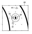
図4は、プレイヤが自車52を操縦してエネミー(敵車)61を追っている様子を示している。自車52と敵車61との最短距離dは、例えば、1000mであり、離れている状態にある。このとき、レーダー画面65の表示倍率は広い範囲の状況を示し、コース形状の確認などを容易にした、相対的に低い倍率m1(長距離モード)で表示されている。このレーダー画面65の拡大したものを図7に示す。レーダー画面65には、敵車61、自車52、コース壁が表示されている。この他に、図示しないチェックポイント、対戦モードにおける他のプレイヤ等を表すキャラクタも表示することが可能である。この表示は、通常、自車のキャラクタを中心として表示され、前後左右の所定範囲が表示される。ゲームの展開状況、例えば、敵車の配置(あるいは分布)状況や特にコースを先見させる必要がある場合等には、自車位置を適宜に画面の中心位置からずらして表示することができる。また、自車52を中心とする所定距離範囲が複数の同心円の距離マーカによって表示される。
【0059】
図5は、プレイヤが自車52を操縦して敵車61を追っている様子を示しており、自車51と敵車61との最短距離dは、例えば、300mである。図4の状態よりも敵車61に近づいている。このとき、レーダー画面65の表示倍率は、コース形状の確認と敵車との相対位置を示すべく中程度の表示倍率m2(中距離モード)に設定される。これを図8に示す。なお、同図において図7と対応する部分には同一符号を付し、かかる部分の説明は省略する。
【0060】
図6は、プレイヤが自車52を操縦して敵車61を追っている様子を示している。自車52と敵車61との最短距離は、50mであり、更に敵車61に接近している。この状態では、ゲームルール上、敵車61から攻撃を受ける可能性がある。このとき、レーダー画面65の表示倍率は、自車52と敵車61との相対位置や、自車の危険度を判断しやすくするために、相対的に高い表示倍率m3(近距離モード)に設定される。これを図9に示す。なお、同図においても図7と対応する部分には同一符号が付されている。
【0061】
図6の画面60の場面では、自車52の後方に敵車61が近づいている。この敵車61は、まだ仮想カメラの視野内に入っていないため画面60に映っていないが、レーダー表示範囲(領域)内に入ったため、レーダー画面65には、自車左後方に敵車61が表示されている(図9参照)。
【0062】
図10は、自車と他車との最短距離に応じて設定されるレーダー画面の表示倍率を切替える際の、履歴動作を説明する説明図である。
【0063】
図示の例では、例えば、レーダー画面の表示モードが自車と敵車との相互間の距離に応じた3つのモード、すなわち、接近モード1、中距離モード2、長距離モード3、に設定されている。接近モード1では、拡大・縮小の表示倍率はm3、中距離モードでは同m2、長距離モードでは同m1(m3>m2>m1)に設定される。
【0064】
そして、自車・敵車の離間距離が基準aを越えて広がると、基準aを所定値だけ更に越えた時点(例えば、基準値aの110%値)で、接近モード1から中距離モード2に移行する。また、中距離モード2において、離間距離が基準bを越えて広がると、基準bを所定値だけ更に越えた時点(例えば、基準値bの110%値)で、中距離モード2から遠距離モード3に移行する。逆に、遠距離モード3において、自車・敵車の離間距離が基準bを越えて減少すると、基準bから更に所定値だけ減少した時点(例えば、基準値bの90%値)で、遠距離モード3から中距離モード2に移行する。また、中距離モード2において、離間距離が基準aを越えて減少すると、基準値aから更に所定値だけ減少した時点(例えば、基準値aの90%値)で、中距離モード2から接近モード1に移行する。
【0065】
このように、離間距離の増加傾向と減少傾向とで表示モード切替の閾値をシフトすることにより、離間距離が閾値近傍で揺らいだ場合に生じ得る、頻繁なレーダー画面のモード切替による見難さを回避することが可能である。離間距離が増加傾向にあるか、減少傾向にあるかは、前回計算の離間距離と今回計算の離間距離とを比較することにより、判別可能である。
【0066】
図11は、レーダー画面の表示モード相互間の切替の際に、レーダー画面の表示倍率を一方値から他方値に連続的に変化して表示モードの移行を自然に見せる例を説明する説明図である。
【0067】
例えば、現在の表示モードが接近モード1であるときに、離間距離が増加して中距離モード2へのモード変更が決定されると、時刻t1から表示倍率m3を徐々に減少させ、時刻t2において規定の表示倍率m2になると、表示倍率の減少を停止する。逆に、現在のモードが中距離モード2であるときに、接近モードへ変更が決定されると、時刻t1から表示倍率m2を徐々に増加させ、時刻t2において規定の表示倍率m3になると、表示倍率の増加を停止する。
【0068】
図12は、レーダー画面の表示倍率切替の制御アルゴリズムを説明するフローチャートである。
【0069】
まず、CPU101は、レーダー画面の現在の表示モードに対応した表示倍率を内部の状態レジスタに設定することによって、レーダー画面形成ルーチン(図示せず)に自車の周囲の様子を表示倍率に対応した範囲のコース地図で表示させている。CPU101は、図示しない主制御プログラム中のレーダー画像形成の条件分岐においてレーダー画像を表示すべきことを判別し、図示のフローチャートの制御アルゴリズムを実行する。
【0070】
CPU101は、仮想三次元ゲーム空間において、自車と複数の敵車各々との各相互間の距離を計算する。これ等の複数の距離のうちの最短距離を抽出する(S202)。現在のレーダー画面の表示モードを内部の状態レジスタから読出す(S204)。この状態レジスタは、ゲーム進行において必要なパラメータを保持しており、その中には現在のレーダー画面の表示モードが含まれる。自車と敵車との相互間の距離と、現在のモードと、からレーダー画面の表示モードを切替えるかどうかを判断する(S206)。表示モードを切替えない場合(S206;No)、現在のままの拡大率でレーダー画像の形成を行う(S210)。
【0071】
表示モードを切替える場合(S206;Yes)、当該ビデオフレームにおけるレーダー画面の表示倍率を計算する(S208)。表示モードの切替の際には、図10を参照して説明した、履歴動作を行うのがよい。表示倍率の計算は、例えば、現在の表示モード(接近モード1、中距離モード2、遠距離モード3)と、自車及び最も近い敵車相互間の距離dとによって画面表示倍率D(=f(d))を定めた、図10の如きテーブルを予めメモリに記憶しておき、これを距離値dによって参照する。上記テーブルは、CD−ROMによって提供されるアプリケーションソフトのデータ読み込みの際にメモリに導入される。
【0072】
表示倍率の変更に際しては、上述した図11に示したように、表示倍率を緩やかに変更するのが望ましい。このようにする表示倍率計算の一例について説明する。
【0073】
ある画像のフレームにおける現在のレーダー画面の拡大率をWo、移行先のモードの拡大率をW’、拡大の程度を移行推進率α(例えば、0.05)として定めると、次のフレームのレーダー拡大率Wは、W=Wo+(W’−Wo)*αで表される。同様に、縮小率は、W=Wo−(Wo−W’)*αで表される。この拡大率若しくは縮小率を当該フレームにおける表示倍率として設定する(S208)。
【0074】
この表示倍率を画像形成のパラメータとして使用してレーダー画像を形成する(S210)。小画面に表示されるコースマップの表示範囲が設定された表示倍率に対応して変更される。
【0075】
なお、図10に、2点鎖線で示すように、表示倍率の関数D=f(d)の特性における表示モード切替区間を傾斜特性とすることによっても同様の効果が期待できる。
【0076】
画像形成後、主プログラムに戻る。形成されたレーダー画像はカメラ画像と合成されてモニタ画面6に表示される。この処理はビデオ信号のフレーム周期で繰返される。
【0077】
この実施の形態では、自車と他車との距離(車間距離パラメータ)をレーダー画面(小画面)の表示切替の契機としているが、これに限られるものではない。例えば、自車の速度の程度(速度パラメータ)によってレーダー画面の表示倍率を切替えることとしても良い。通常、高速で走る程、より先方のコース状況を知る必要がある。
【0078】
また、自車が進入するコース(マップ)の状態(コースの特徴パラメータ)に応じてレーダー画面の表示倍率を切替えることとしても良い。例えば、自車がコーナリングの難しいカーブに近づく場合、自車から該カーブの入口まで所定距離になると、遊技者に対して広範囲を表示するレーダー画面で早めにカーブの存在を示し、カーブの入口から出口までのカーブの全体形状を知らしめる。また、自車がカーブにさしかかったときは、狭い範囲を表示する、相対的に拡大されたレーダー画面で走行中のコーナー形状を詳しく知らしめる。
【0079】
また、ゲーム展開中に、ゲーム画面に表示されない位置で出来事(イベント)が発生した場合に、そのイベントが発生した場所と自車の場所との関係が分り易いようにするため、例えば、イベント発生点と自車位置との距離に基づいて小画面の表示縮尺を変更して、これ等の表示を行うようにすることが可能である。
【0080】
また、これ等レーダー画面の表示倍率を切り替える条件を組み合わせても良い。
【0081】
本発明の他の実施の形態について、図13乃至図16を参照して説明する。
【0082】
図13及び図14に示される例では、画面60の下方に、プレイヤ51の後方に迫ってくる敵車が、該敵車を表すシンボルとしての、「十字形」のチェックマーク68によって表示されている。各図中のレーダー画面65に自車と敵車の離間距離は示されるが、敵車を表すシンボルであるチェックマーク68はプレイヤ51からの距離に応じた大きさに設定される。すなわち、自車と敵車とが離れている場合には、マーク68の外形は小さく、近接した場合にはマーク68の外形は大きく表示される。また、チェックマーク68の画面60の水平方向の表示位置は、仮想空間内のレースコースの幅方向における位置に対応して表示される。チェックマーク68は、その存在がプレイヤの妨げにならないように背後を見せるべく半透明表示され、時計回り方向に回転して、プレイヤの後方への注意を喚起する。このチェックマークは、後方の状況を表示する後方レーダーとして機能する。チェックマークの回転の速さは、後方敵車の追い上げの度合いや敵の危険度に応じて設定することが可能である。
【0083】
なお、チェックマーク68の形状は、三角形、四角形等の多角形や、車両の形状、ゲームキャラクタの顔等種々の形状のものを使用することができ、後方から迫る車種や敵の種類に応じたデザインとすることができる。
【0084】
図15は、後方チェックマークの表示アルゴリズムを示している。図示しないメインプログラムにおいて、レースコースを複数の車両が走行しており、仮想カメラがプレイヤの後方位置(例えば、客観位置)から追跡している場合に、CPU101は同図に示すルーチンを実行する。
【0085】
まず、図16に点線で示すように、仮想カメラで捉えた画面(視野)の範囲内に、自車52の後方に位置する敵車61が存在するかどうかを判別する(S302)。既に、敵車61が画面60に映っている場合には、画像として敵車61を見ることができるので、敢て後方チェックマーク68を表示する必要はない。そこで、後方チェックマークの表示ルーチンを終了する(S302;Yes)。
【0086】
自車52後方の敵車61が画面に映っていない場合(S302;No)、仮想カメラ若しくは自車52から所定距離範囲内に敵車61が存在するどうかを判別する。所定距離としては、例えば、カメラの前方にlf[m](例えば、50m)、後方にlb[m](例えば、100m)とする(S304)。所定距離内に、敵車61が存在しない場合には(S304;No)、後方チェックマークの表示は必要ないので、本ルーチンを終了する。
【0087】
所定距離内に、敵車61が存在する場合には(S304;Yes)、自車52と、当該後方の敵車61との仮想空間における距離d2を計算する。なお、この距離は、仮想カメラ位置から該後方の敵者61との距離を求めることとしても良い。所定距離内に存在する複数の敵車61の各々について自車との離間距離d2を求める。各敵車61についてチェックマーク68を用意し、各チェックマーク68の大きさを当該離間距離d2に対応して定める。このチェックマークを所定角度回転する。また、各チェックマーク68の画面左右方向(水平方向)の表示位置を、該当する敵車61のレースコースの幅方向における位置に対応して定める。このように形成された各チェックマーク68は、画像合成装置116によって背景画像と合成される(S306)。その後、メインプログラムに戻る。
【0088】
このような処理を該当する場合に各フレーム毎に行って、自車52と敵車61との距離、位置に応じてそれぞれ大きさ及び表示位置が設定され、更に回転するチェックマーク68が追加された画像が表示される。
【0089】
ところで、通常、この種の3次元仮想空間内に配置したオブジェクトを遊技者が操作してゲームを展開するようなシステムにおいては、当該3次元空間内の仮想カメラから見た画像を表示装置にの画面に表示し、ゲームを進行させる。遊技者がゲームを行い易いようにするため、多くのゲームには、仮想カメラの位置を変更して、表示装置に表示する機能が付与されている。遊技者が選択した位置からの画像が提供できるようになっている。例えば、第1の視点位置としてのドライバ視点と、第2の視点位置としての客観視点位置である。勿論、第3の視点位置、あるいは任意の視点位置に仮想カメラを配置して車両の走行等を追跡することが可能である。
【0090】
一般的に、プレイヤがゲーム操作を行い易い仮想カメラの位置は、自機52の後方から少し離れた位置にカメラが位置する客観視点位置である。この場合、自機52の全体とその周辺の状況が表示装置、すなわち、モニタ6の画面60に表示される。一方、よりリアルにゲームを楽しみたい場合には、仮想空間内のプレイヤキャラクタ51の目の位置に仮想カメラを設定するドライバ視点位置が好まれる。このドライバ視点位置の場合は、基本的には自機52の前方のみがカメラに見えることとなり、プレイヤは自機52の後方の状態をゲーム画面60で知ることができない。特に、上述したような、後方から出現する他機61からの攻撃を受ける可能性のあるゲームの場合は、表示装置の画面上に表示されない後方からの攻撃を受けることとなり、遊技者にとっては、極めて不利益である。そこで、後方からの他機61の接近についてのインフォメーションを表示するのが望ましい。また、客観視点の場合は、自機52の周辺が既にある範囲内で表示されているので、むしろ、当該インフォメーションがないほうが良い場合もある。そこで、選択されたカメラの視点の位置に応じて当該インフォメーションの出現について制御する。
【0091】
図17は、このような場合の視点切替と連携する後方チェックマーク68の表示アルゴリズムを示している。
【0092】
遊技者によって視点切替スイッチ22が操作されると、入出力インタフェース106を介して図示しない状態レジスタに視点切替フラグが設定される。視点切替スイッチによって仮想空間における仮想カメラの位置データが変更されると、座標変換を行う変換マトリックスのパラメータが新たなカメラ位置のデータによって更新される。すなわち、仮想空間内に配置された各オブジェクトのデータは仮想カメラの変更後の位置に対応した視野の視点座標系(view coordinates)に変換され、更に透視変換(perspective transformation)によってスクリーン座標系に変換されてレンダリングが行われ、モニタ6のゲーム画面60が新たな仮想カメラの位置・視線ベクトルに対応した画像に切り替わる。なお、視点の切替は、視点切替スイッチ22の操作によるものに限られない。例えば、CPUが特定の胃弁の発生に対応して視点切替を行うこととしても良い。
【0093】
CPU101が、図示しないメインプログラムにおいて、上記視点切替フラグの設定を判別すると同図に示すルーチンを実行する。
【0094】
まず、視点切替によって指定された仮想カメラの視点位置がドライバ視点か、客観視点かを判別する(S402)。カメラ視点が客観視点であるとき、後方の敵車61をある程度ゲーム画面60に映すことが可能である(自車52の後方の、自車52に接近したある範囲内に存在する敵車61は、自車52の後上方に位置する仮想カメラの視野範囲内に入り、ゲーム画面60に映し出される)ので、後方チェックマーク68を形成することなくルーチンを終了する(S402;客観視点)。
【0095】
ドライバ視点である場合(S402;ドライバ視点)、自車52の後方はゲーム画面60に映らないので、自車52後方の所定距離範囲内に敵車が存在するかどうか、あるいは仮想カメラから所定距離範囲内に敵車が存在するどうかを判別する(S404)。所定距離内に、例えば、自車52の後方150m以内に、敵車61が存在しない場合には(S404;No)、後方チェックマーク68の表示は必要ないので、本ルーチンを終了する。
【0096】
所定距離内に、敵車が存在する場合には(S404;Yes)、自車51と、所定距離内に存在する当該後方の敵車61との仮想空間における離間距離d2を計算する。なお、この距離は、仮想カメラ位置から後方の敵車61との距離を求めることとしても良い。所定距離内に存在する各敵車61について離間距離d2を求める。各敵車61についてチェックマーク68を用意し、各チェックマーク68の大きさを当該距離に対応して定める。このチェックマーク68を時計回りに所定角度回転する。また、各チェックマーク68の画面左右方向(水平方向)の表示位置を各敵車61のレースコースの幅方向における位置、あるいは視点座標系における左右方向(x座標)の位置に対応して定める。このように形成された各チェックマークは、画像合成装置116によって背景画像と合成される(S406)。その後、CPU101の処理はメインプログラムに戻る。
【0097】
なお、ステップS404及びS406は、それぞれ既述したステップS304及びS306に対応するので、プログラムでは、ステップS402のドライバ視点選択からステップS302及びS304に移行することとしても良い。
【0098】
このような処理を該当する場合に各フレーム毎に行うことにより、ドライバ視点モードでゲームを展開すると、適宜に、自車と後方敵車との距離、位置を表すチェックマークがゲーム画面中に表示される。これにより、自車の後方が見えないドライバ視点モードにおける不利を軽減することが可能となる。ただし、本発明はドライバ視点モードに限定されるものではない。例えば、自車の前方がモニタに映るが、自車の後方はモニタに映らない(あるいは映り難い)ような、ドライバ視点以外のカメラ位置であっても良い。
【0099】
なお、上述した実施の形態では、オブジェクトとしてオートバイを例にして説明しているが、これに限られるものではない。例えば、図18(A)及び同(B)に示すように、遊技者が操縦するロボットP1とコンピュータ若しくは対戦相手が操縦するロボットP2であっても良い。この画面中に上述した小画面(図示せず)を表示する。更に、オブジェクトとしては、4輪車、戦車、戦闘機、ヘリコプタ、モータボート、ジェットスキー、スキー、スノーボード、ソリ、人、動物、ゲームキャラクタ等の種々のものが考えられる。
【0100】
実施例では、ゲーム装置のプログラムやデータはROMによって提供されているが、他の情報記録媒体、例えば、FDD、CD−ROM、DVD、HDDであっても良い。また、インターネット等の通信網その他の通信回線を通してプログラムやデータをダウンロードしても良い。
【0101】
【発明の効果】
以上説明したように、本発明のゲーム装置及びゲーム装置の画像表示方法によれば、自機の周囲の状況を表示するゲーム画面内の小画面が、自機と他機との距離等の種々の条件に応じた表示倍率あるいは縮尺でモニタの画面に表示されるので、コース状況や他機との位置関係を把握し易い小画面が得られて好ましい。
【0102】
また、画面に映らない自機の後方の他機が後方チェックマークでゲーム画面中に表示されるので、カメラ視点変更等によって後方が画面に映らない状態でゲームを行う場合等に具合がよい。
【図面の簡単な説明】
【図1】本発明の実施の形態に係るゲーム装置の概略を示す斜視図である。
【図2】同実施の形態におけるオートバイ型操作機の一部を示す平面図である。
【図3】同実施の形態のゲーム装置を示すブロック図である。
【図4】自車と敵車との距離が遠距離である場合の、画面表示例を示す説明図である。
【図5】自車と敵車との距離が中距離である場合の、画面表示例を示す説明図である。
【図6】自車と敵車との距離が近距離である場合の、画面表示例を示す説明図である。
【図7】遠距離モードにおけるレーダー画面65の表示例を示す説明図である。
【図8】中距離モードにおけるレーダー画面65の表示例を示す説明図である。
【図9】近距離(接近)モードにおけるレーダー画面65の表示例を示す説明図である。
【図10】自車と敵車との相互間の距離に応じてレーダー画面の表示倍率(拡大・縮小)を切替える際の工夫を説明する説明図である。
【図11】レーダー画面の表示切替の際に、表示倍率を徐々に変えて表示が違和感なく移行するようする例を説明する説明図である。
【図12】レーダー画像形成のアルゴリズムを説明するフローチャートである。
【図13】画面に後方の敵車の接近を知らせるチェックマークを表示するようにした例を示す説明図である。
【図14】画面に後方の敵車の接近を知らせるチェックマークを表示するようにした例を示す説明図である。図13の場合よりも、後方の敵車の接近している。
【図15】画面に後方チェックマークを表示するアルゴリズムを説明するフローチャートである。
【図16】仮想カメラ位置と後方の敵車との関係を説明する説明図である。
【図17】画面に後方チェックマークを表示する他のアルゴリズムを説明するフローチャートである。
【図18】他のオブジェクトの例を説明する説明図である。
【符号の説明】
1 ゲーム装置
2 オートバイ型操作機
3 ゲーム機本体
5 筐体
6 ディスプレイ
7 スピーカ
8 マザーボード
22 視点切替ボタン
30 音響・ゲーム処理回路
31 入力装置
32 出力装置
51 プレイヤ
61 敵車[0001]
[Industrial application fields]
The present invention relates to a game device, for example, an object that imitates a car or the like is placed in a virtual space, and a state in which the object is moved in response to an operation from a player is displayed on a display to play a game. The present invention relates to a game device equipped with a program.
[0002]
[Prior art]
With the development of computer technology, game devices are required to have clearer and more realistic images regardless of whether they are for home use or business use. A game apparatus generally includes a game apparatus main body including a computer apparatus that executes a pre-stored game program, an operating device that gives an operation signal to the computer apparatus to move an object to be expressed in the game and other commands, A display for displaying an image associated with game proceeding (game proceeding) by executing a game program on the computer device, and an acoustic device for generating sound associated with the game development are provided.
[0003]
There is a game device that handles a driving game (auto racing game) as one field of the game device having such a configuration.
[0004]
There is also a game in which a fighting fighting game is advanced while moving an object freely in a virtual space based on an operation signal from a player.
[0005]
In such a game, a simplified map on the game screen to show the player's manipulated objects and enemy positions in the virtual space, and to show the surrounding situation to the player easily, An auxiliary information screen such as a so-called radar screen showing the arrangement of objects such as enemies and allies is displayed.
[0006]
[Problems to be solved by the invention]
However, when an auxiliary information screen that allows the player to manipulate the object (hereinafter referred to as the player's own device) to be distantly displayed is superimposed on the game screen, a large range of the virtual space is reduced and displayed. Become. Then, the information on the own device and the surroundings of the own device are displayed relatively small, and it is difficult to obtain detailed information.
[0007]
In view of the above points, if only the vicinity of the object is to be displayed in order to provide detailed surrounding auxiliary information, the situation that will be developed next (for example, located far away, Since it is difficult to grasp the objects controlled by other players and computer programs (hereinafter referred to as other machines), etc., it is difficult to predict the movement of the own machine and the game development at high speed. There was a problem of becoming.
[0008]
On the other hand, in the case of a game in which a game is developed while aiming for a goal by progressing through a race course and attacking and defending with another machine, the relative position between the other machine and the own machine can be grasped more effectively. Should be. Further, if necessary, it should be easy for the player to grasp the subsequent development of the game, for example, the race course.
[0009]
Therefore, a first object of the present invention is to provide a game device that displays an auxiliary screen that allows the user to know the detailed shape of the course to be developed next in the game screen.
[0010]
A second object of the present invention is to provide a game device having an auxiliary screen for displaying the relative position between the own device and the other device so as to easily grasp the relative position.
[0011]
A third object of the present invention is to provide a game device that displays information related to other devices existing behind the player device.
[0012]
[Means for Solving the Problems]
In order to achieve the above object, the game device of the present invention shows a game in which a first object controlled by a player and a second object controlled by a computer or an opponent develop in a virtual space. In the game device displayed on the monitor screen, support screen forming means (S210) for forming a small screen in the monitor screen for displaying (or showing) information for supporting the control of the first object, and in the virtual space Display mode change determining means (S206) for determining whether or not a predetermined condition for changing the display magnification of the small screen in game development is satisfied, and setting the display magnification of the small screen based on the determination result Display magnification setting means (S208).
[0013]
For example, the predetermined condition is whether or not the distance between the first and second objects exceeds a reference value.
[0014]
For example, the predetermined condition is whether or not the moving speed of the first object exceeds a reference value.
[0015]
For example, the predetermined condition is whether or not the first object moves to a predetermined location in the virtual space.
[0016]
For example, the predetermined condition is whether or not a predetermined event has occurred in the virtual space.
[0017]
The game device of the present invention displays a game screen in which a first object controlled by a player and a second object controlled by a computer or an opponent are developed in a virtual space on a monitor screen. In the apparatus, support screen forming means (S210) for forming a small screen representing a surrounding situation centered on the first object in the monitor screen, the first object and the second object in the virtual space, A distance calculation means (S202) for calculating the separation distance, a display magnification setting means (S208) for setting a display magnification corresponding to the separation distance from a plurality of predetermined display magnifications for the small screen, and the setting When the display magnification is increased from the current value and when the display magnification is decreased, the correspondence between the separation distance and the display magnification is determined. The made different historical operating means (S208, FIG. 10) to perform the historical operating the setting of the display magnification provided with, the.
[0018]
Preferably, the display magnification setting means gradually shifts the display magnification from the current value to the display magnification to be set when setting the display magnification (FIG. 11).
[0019]
For example, the small screen includes a course diagram, and the display magnification setting means sets the scale of the course diagram according to the separation distance (FIGS. 7 to 9).
[0020]
For example, there are a plurality of the second objects, and the distance calculation means calculates each separation distance between the first object and each of the plurality of second objects, and outputs the shortest separation distance among them. .
[0021]
With this configuration, when there is no other device (or vehicle) that is the second object nearby, the display scale (or display magnification) of the small screen is set large, so that the player can It becomes easy to grasp the relative positional relationship between the own machine (or own vehicle) as an object and the other vehicle. Further, when there is no other vehicle nearby, the display scale of the small screen is set to be small, so that the player can see the course shape of the race in a wide range. This is a game support screen suitable for a game that develops a race while fighting. In addition, frequent switching of screens can be avoided.
[0022]
The game device of the present invention displays on a monitor screen the state of a game in which a first object controlled by a player and a second object controlled by a computer or an opponent develop in a virtual space. In the game device, distance calculation means (S306) for calculating a separation distance between the first object or virtual camera in the virtual space and a second object located behind the first object, and the second object A symbol forming means (S306) of a rear object that displays a symbol on the monitor screen with a symbol having a size corresponding to the separation distance.
[0023]
With such a configuration, it is possible to alert the player about another machine (or another car) that is a second object approaching from behind, which is not displayed on the screen during the game.
[0024]
The game device of the present invention monitors a state of a game in which a first object controlled by a player and a second object controlled by a computer or an opponent are developed in a virtual space by a virtual camera, In the game device that displays this on the screen of the monitor, the position of the virtual camera is the first position where the front of the first object can be seen from the position of the object or a position near the object, and the first Camera position switching command means (22) for issuing a switching command for switching to the second position where the front can be seen from behind the object, and when the second object exists behind the first object (S404), In response to the switching command to switch the position of the virtual camera to the first position (S402), the second The symbol representing the object comprises a symbol display means (S406) to be displayed on the screen of the monitor.
[0025]
In addition, the game device of the present invention uses a virtual camera to monitor the state of a game in which a first object controlled by a player and a second object controlled by a computer or an opponent are developed in a virtual space. In the game apparatus that displays this on the screen of the monitor, the position of the virtual camera is the first position that displays the front of the first object and does not display the back of the first object, and the rear of the first object. When the second object exists behind the first object (S404), the camera position switching command means (22) for issuing a switching command for switching from the first position to the second position where the front can be seen. In response to the switching command to switch the position of the second object to the first position (S402), a symbol representing the second object is Serial and a symbol display means for displaying in the monitor screen (S406).
[0026]
Preferably, the symbol display means calculates a distance between the first object or the virtual camera in the virtual space and the second object existing behind the first object. (S406) and symbol forming means (S406) for displaying the rear second object on the monitor screen with a symbol having a size corresponding to the separation distance.
[0027]
Preferably, the symbol forming means further determines a display position of the symbol on the monitor screen in correspondence with a position of the rear second object in the virtual space.
[0028]
By adopting such a configuration, it becomes possible to appropriately display the information of the rear object that is no longer visible on the game screen by switching the camera viewpoint on the game screen.
[0029]
According to the image display method of the game device of the present invention, a game screen in which a first object controlled by a player and a second object controlled by a computer or an opponent develop in a virtual space is displayed on a monitor screen. In the image display method in the game device to be displayed on the screen, a small screen forming process (S210) for forming a small screen displaying the state around the first object in the virtual space in the monitor screen, and in the virtual space In the game development, a determination process (S206) for determining whether or not the display of the small screen corresponds to a condition that should be an enlarged display or a reduced display, and when the above condition is satisfied, the display of the small screen is displayed. And a display change process (S208) for changing to enlarged display or reduced display.
[0030]
With this configuration, the content displayed on the small screen is displayed at an appropriate display magnification (or scale) that is enlarged or reduced in accordance with a predetermined condition during game development. For this reason, it becomes possible to effectively show necessary information as a whole display or a partial display of a small screen having a small display area.
[0031]
Preferably, the predetermined condition is that (a) the distance between the first and second objects exceeds a reference value, (b) the moving speed of the first object exceeds a reference value, (c) at least one of the first object moving to a predetermined location in the virtual space, and (d) whether a predetermined event has occurred in the virtual space. It is.
[0032]
Preferably, the display changing process further includes the first object displayed on the small screen without changing a size of the entire small screen by gradually changing a display magnification of the small screen. Gently enlarge or reduce the outer area of the area.
[0033]
Preferably, the small screen forming process further displays the first and second objects as symbols on a course map of the game, and the display changing process further includes a step between the first and second objects. The scale of the course map is set according to the distance between the course maps.
[0034]
An information recording medium according to the present invention records a computer program that causes a computer system to function as the above-described game device.
[0035]
The information recording medium according to the present invention records a program that causes a computer system to execute the above-described image display method.
[0036]
DETAILED DESCRIPTION OF THE INVENTION
Embodiments of the present invention will be described below with reference to the drawings. FIG. 1 is a perspective view showing an example of an embodiment of a game device for a driving game according to the present invention. FIG. 2 is a plan view around the handle of the motorcycle-like operating machine.
[0037]
As shown in the figure, the
[0038]
In addition, a display 6 of the game machine
[0039]
The game processing unit in the sound / game processing circuit mounted on the motherboard 8 has a built-in computer device for executing a game program stored in advance. The
[0040]
The motorcycle-
[0041]
The motorcycle-
[0042]
The
[0043]
A
[0044]
Further, a sensor for detecting the movement angle of the
[0045]
Further, the
[0046]
FIG. 3 is a block diagram showing a configuration example of the game processing circuit of the game device according to the present invention. The
[0047]
The operation detection sensor for the
[0048]
The game processing unit in the sound /
[0049]
The CPU 101 is connected to a
[0050]
The input /
[0051]
In the example of the present embodiment, the CPU 101 uses an operation signal from the motorcycle-
[0052]
The image processing of a motorcycle simulates the movement of a motorcycle in a virtual space by an operation signal from the motorcycle-
[0053]
The
[0054]
The
[0055]
The scroll
[0056]
4 to 6 show examples displayed on the
[0057]
In each figure, the
[0058]
FIG. 4 shows a state in which the player is following the enemy (enemy vehicle) 61 by manipulating the
[0059]
FIG. 5 shows a state in which the player steers the
[0060]
FIG. 6 shows a state where the player is driving the
[0061]
In the scene of the
[0062]
FIG. 10 is an explanatory diagram for explaining the history operation when the display magnification of the radar screen set according to the shortest distance between the own vehicle and the other vehicle is switched.
[0063]
In the illustrated example, for example, the display mode of the radar screen is set to three modes corresponding to the distance between the host vehicle and the enemy vehicle, that is, the
[0064]
When the separation distance between the host vehicle and the enemy vehicle increases beyond the reference a, when the reference a is further exceeded by a predetermined value (for example, 110% of the reference value a), the
[0065]
In this way, by shifting the display mode switching threshold according to the increasing tendency and decreasing tendency of the separation distance, the difficulty in viewing due to frequent mode switching of the radar screen that may occur when the separation distance fluctuates near the threshold value. It is possible to avoid it. Whether the separation distance tends to increase or decrease can be determined by comparing the separation distance calculated last time with the separation distance calculated this time.
[0066]
FIG. 11 is an explanatory diagram for explaining an example in which the display magnification of the radar screen is continuously changed from one value to the other value so that the transition of the display mode can be seen naturally when switching between the display modes of the radar screen. is there.
[0067]
For example, when the current display mode is the
[0068]
FIG. 12 is a flowchart illustrating a control algorithm for switching the display magnification of the radar screen.
[0069]
First, the CPU 101 sets the display magnification corresponding to the current display mode of the radar screen in the internal state register, so that the surroundings of the vehicle correspond to the display magnification in the radar screen formation routine (not shown). It is displayed on the course map of the range. The CPU 101 determines that a radar image should be displayed in a conditional branch for radar image formation in a main control program (not shown), and executes a control algorithm in the flowchart shown in the drawing.
[0070]
The CPU 101 calculates the distance between each of the own vehicle and each of the plurality of enemy vehicles in the virtual three-dimensional game space. The shortest distance among these plural distances is extracted (S202). The display mode of the current radar screen is read from the internal status register (S204). This status register holds parameters necessary for the progress of the game, and includes the current radar screen display mode. It is determined whether or not to switch the display mode of the radar screen from the distance between the host vehicle and the enemy vehicle and the current mode (S206). When the display mode is not switched (S206; No), a radar image is formed with the current enlargement ratio (S210).
[0071]
When the display mode is switched (S206; Yes), the display magnification of the radar screen in the video frame is calculated (S208). When the display mode is switched, the history operation described with reference to FIG. 10 is preferably performed. The display magnification is calculated by, for example, the screen display magnification D (= f) based on the current display mode (
[0072]
When changing the display magnification, it is desirable to change the display magnification gradually as shown in FIG. An example of display magnification calculation in this way will be described.
[0073]
If the enlargement rate of the current radar screen in a frame of an image is Wo, the enlargement rate of the transition mode is W ′, and the degree of enlargement is a transition promotion rate α (for example, 0.05), the radar of the next frame The enlargement ratio W is expressed by W = Wo + (W′−Wo) * α. Similarly, the reduction ratio is expressed by W = Wo− (Wo−W ′) * α. This enlargement ratio or reduction ratio is set as the display magnification in the frame (S208).
[0074]
A radar image is formed using the display magnification as an image formation parameter (S210). The course map display range displayed on the small screen is changed in accordance with the set display magnification.
[0075]
Note that, as shown by a two-dot chain line in FIG. 10, the same effect can be expected by setting the display mode switching section in the characteristic of the display magnification function D = f (d) to the inclination characteristic.
[0076]
After image formation, return to the main program. The formed radar image is combined with the camera image and displayed on the monitor screen 6. This process is repeated at the frame period of the video signal.
[0077]
In this embodiment, the distance (inter-vehicle distance parameter) between the own vehicle and another vehicle is used as an opportunity for switching the display of the radar screen (small screen), but the present invention is not limited to this. For example, the display magnification of the radar screen may be switched depending on the speed of the host vehicle (speed parameter). Usually, the faster you run, the more you need to know the course ahead.
[0078]
Also, the display magnification of the radar screen may be switched according to the state (course characteristic parameter) of the course (map) in which the host vehicle enters. For example, when the vehicle approaches a curve that is difficult to corner, when the vehicle reaches a predetermined distance from the entrance to the curve, the radar screen that displays a wide range for the player shows the existence of the curve earlier, and from the entrance of the curve Inform the entire shape of the curve to the exit. When the vehicle approaches a curve, the corner shape during traveling is informed in detail on a relatively enlarged radar screen that displays a narrow range.
[0079]
In addition, when an event occurs at a position that is not displayed on the game screen during game development, for example, an event occurs to make it easier to understand the relationship between the location where the event occurred and the location of the vehicle. It is possible to change the display scale of the small screen based on the distance between the point and the vehicle position, and to display these.
[0080]
Further, these conditions for switching the display magnification of the radar screen may be combined.
[0081]
Another embodiment of the present invention will be described with reference to FIGS.
[0082]
In the example shown in FIG. 13 and FIG. 14, an enemy vehicle approaching to the rear of the
[0083]
The
[0084]
FIG. 15 shows a display algorithm for the backward check mark. In a main program (not shown), when a plurality of vehicles are running on the race course and the virtual camera is tracking from the rear position (for example, objective position) of the player, the CPU 101 executes a routine shown in FIG.
[0085]
First, as shown by a dotted line in FIG. 16, it is determined whether or not the
[0086]
When the
[0087]
When the
[0088]
Such processing is performed for each frame, the size and display position are set according to the distance and position between the
[0089]
By the way, usually, in a system in which a player operates an object placed in this kind of three-dimensional virtual space and develops a game, an image viewed from the virtual camera in the three-dimensional space is displayed on a display device. Display on the screen and advance the game. In order to make it easier for players to play games, many games have a function of changing the position of a virtual camera and displaying it on a display device. An image from a position selected by the player can be provided. For example, the driver viewpoint as the first viewpoint position and the objective viewpoint position as the second viewpoint position. Of course, it is possible to track the running of the vehicle by arranging a virtual camera at the third viewpoint position or an arbitrary viewpoint position.
[0090]
In general, the position of the virtual camera at which the player can easily perform the game operation is an objective viewpoint position where the camera is located at a position slightly away from the rear of the
[0091]
FIG. 17 shows a display algorithm of the
[0092]
When the viewpoint switch 22 is operated by the player, a viewpoint switching flag is set in a state register (not shown) via the input /
[0093]
When the CPU 101 determines that the viewpoint switching flag is set in the main program (not shown), the routine shown in FIG.
[0094]
First, it is determined whether the viewpoint position of the virtual camera designated by viewpoint switching is a driver viewpoint or an objective viewpoint (S402). When the camera viewpoint is an objective viewpoint, it is possible to project the
[0095]
If it is the driver's viewpoint (S402; driver viewpoint), the rear of the
[0096]
If there is an enemy vehicle within the predetermined distance (S404; Yes), the distance d2 in the virtual space between the
[0097]
Note that steps S404 and S406 correspond to steps S304 and S306, respectively, so that the program may shift from the driver viewpoint selection in step S402 to steps S302 and S304.
[0098]
When such a process is performed for each frame, when the game is developed in the driver viewpoint mode, check marks indicating the distance and position between the host vehicle and the rear enemy vehicle are appropriately displayed on the game screen. Is done. Thereby, it becomes possible to reduce the disadvantage in the driver viewpoint mode in which the rear of the host vehicle is not visible. However, the present invention is not limited to the driver viewpoint mode. For example, it may be a camera position other than the driver's viewpoint such that the front of the own vehicle is reflected on the monitor but the rear of the own vehicle is not reflected on the monitor (or is difficult to be reflected).
[0099]
In the above-described embodiment, the motorcycle is described as an example of the object. However, the present invention is not limited to this. For example, as shown in FIGS. 18A and 18B, a robot P1 operated by a player and a robot P2 operated by a computer or an opponent may be used. The small screen (not shown) described above is displayed in this screen. Further, various objects such as four-wheeled vehicles, tanks, fighters, helicopters, motor boats, jet skis, skis, snowboards, sleds, people, animals, and game characters can be considered as objects.
[0100]
In the embodiment, the program and data of the game device are provided by the ROM, but other information recording media such as an FDD, a CD-ROM, a DVD, and an HDD may be used. Further, programs and data may be downloaded through a communication network such as the Internet or other communication lines.
[0101]
【The invention's effect】
As described above, according to the game device and the image display method of the game device of the present invention, the small screen in the game screen for displaying the situation around the player's own device has various distances such as the distance between the player's own device and the other device. Is displayed on the monitor screen at a display magnification or scale corresponding to the above conditions, and it is preferable that a small screen that allows easy understanding of the course status and the positional relationship with other machines can be obtained.
[0102]
In addition, since the other devices behind the device that is not displayed on the screen are displayed on the game screen with a backward check mark, it is preferable when the game is played in a state where the rear is not displayed on the screen due to a camera viewpoint change or the like.
[Brief description of the drawings]
FIG. 1 is a perspective view showing an outline of a game device according to an embodiment of the present invention.
FIG. 2 is a plan view showing a part of the motorcycle type operating device in the embodiment.
FIG. 3 is a block diagram showing the game device of the embodiment.
FIG. 4 is an explanatory diagram showing a screen display example when the distance between the host vehicle and the enemy vehicle is a long distance.
FIG. 5 is an explanatory diagram showing a screen display example when the distance between the host vehicle and the enemy vehicle is a medium distance.
FIG. 6 is an explanatory diagram showing a screen display example when the distance between the host vehicle and the enemy vehicle is a short distance.
FIG. 7 is an explanatory diagram showing a display example of a
FIG. 8 is an explanatory diagram showing a display example of a
FIG. 9 is an explanatory diagram showing a display example of a
FIG. 10 is an explanatory diagram for explaining a device for switching the display magnification (enlargement / reduction) of a radar screen according to the distance between a host vehicle and an enemy vehicle.
FIG. 11 is an explanatory diagram for explaining an example in which the display magnification is gradually changed when the display of the radar screen is switched so that the display shifts without a sense of incongruity.
FIG. 12 is a flowchart illustrating an algorithm for forming a radar image.
FIG. 13 is an explanatory diagram showing an example in which a check mark notifying the approach of an enemy vehicle behind is displayed on the screen.
FIG. 14 is an explanatory diagram showing an example in which a check mark notifying the approach of an enemy vehicle behind is displayed on the screen. The enemy vehicle behind is closer than in the case of FIG.
FIG. 15 is a flowchart illustrating an algorithm for displaying a backward check mark on a screen.
FIG. 16 is an explanatory diagram illustrating a relationship between a virtual camera position and a rear enemy vehicle.
FIG. 17 is a flowchart illustrating another algorithm for displaying a backward check mark on the screen.
FIG. 18 is an explanatory diagram illustrating an example of another object.
[Explanation of symbols]
1 Game device
2 Motorcycle-type controller
3 Game console
5 Case
6 Display
7 Speaker
8 Motherboard
22 Viewpoint switching button
30 Sound and game processing circuit
31 Input device
32 output device
51 players
61 Enemy vehicle
Claims (5)
前記ゲーム処理部が、前記第1のオブジェクトと、前記複数の第2のオブジェクトとの各相互間の離間距離を算出する算出過程と、
前記ゲーム処理部が、前記算出過程において算出した複数の離間距離のうちの最短離間距離を抽出する抽出過程と、
前記ゲーム処理部が、現在設定されている補助画像の表示倍率を読み取る読取過程と、
前記ゲーム処理部が、前記読取過程において読み取った補助画像の表示倍率と、抽出過程で抽出した最短離間距離とに基づいて、前記表示倍率を変更するか否かを判断する判断過程と、
前記判断過程において前記表示倍率を変更すべきと判断した場合には、前記ゲーム処理部が、前記最短離間距離に応じて表示倍率を再設定する再設定過程と
を含むことを特徴とするゲーム装置の画像表示方法。An input device, a game processing unit, and a display device for displaying an image generated in the game processing unit, a first object controlled by a player operating the input device, and a computer or an opponent For the plurality of second objects controlled by the above, the game processing unit generates an image according to the progress of the game developed in the virtual space, displays the generated image on the display device, and An image display method for a game device that displays an auxiliary image representing a state of a predetermined distance range centered on the object on the display device at a set display magnification,
A calculation process in which the game processing unit calculates a separation distance between each of the first object and the plurality of second objects;
An extraction process in which the game processing unit extracts a shortest separation distance among a plurality of separation distances calculated in the calculation process;
A reading process in which the game processing unit reads the display magnification of the currently set auxiliary image;
A determination process for determining whether or not to change the display magnification based on the display magnification of the auxiliary image read in the reading process and the shortest separation distance extracted in the extraction process;
A game apparatus comprising: a resetting process in which the game processing unit resets the display magnification according to the shortest separation distance when it is determined that the display magnification should be changed in the determination process; Image display method.
再設定する表示倍率に関し、前記ゲーム処理部が、前記補助画像全体の大きさを変えずに前記表示装置に表示される前記第1のオブジェクトを含む領域の外囲を緩やかに拡大または縮小するように、該表示倍率を徐々に変えることを特徴とする請求項1に記載のゲーム装置の画像表示方法。In the resetting process,
Regarding the display magnification to be reset, the game processing unit gradually enlarges or reduces the outer periphery of the area including the first object displayed on the display device without changing the size of the entire auxiliary image. 2. The image display method for a game apparatus according to claim 1, wherein the display magnification is gradually changed.
再設定する表示倍率に関し、前記ゲーム処理部が、前記表示倍率を現在値から増加する場合と減少する場合とで、前記最短離間距離と前記表示倍率との対応づけを異ならしめて前記表示倍率を再設定することを特徴とする請求項1に記載のゲーム装置の画像制御方法。In the resetting process,
Regarding the display magnification to be reset, the game processing unit re-establishes the display magnification by changing the correspondence between the shortest separation distance and the display magnification depending on whether the display magnification is increased or decreased from the current value. 2. The image control method for a game device according to claim 1, wherein the image control method is set.
再設定する表示倍率に関し、前記ゲーム処理部が、前記表示倍率を現在値から再設定すべき表示倍率に徐々に移行することを特徴とする請求項3に記載のゲーム装置の制御方法。In the resetting process,
The game apparatus control method according to claim 3, wherein the game processing unit gradually shifts the display magnification from a current value to a display magnification to be reset, with respect to the display magnification to be reset.
Priority Applications (1)
| Application Number | Priority Date | Filing Date | Title |
|---|---|---|---|
| JP25667198A JP3887810B2 (en) | 1997-09-12 | 1998-09-10 | Game device |
Applications Claiming Priority (3)
| Application Number | Priority Date | Filing Date | Title |
|---|---|---|---|
| JP9-248081 | 1997-09-12 | ||
| JP24808197 | 1997-09-12 | ||
| JP25667198A JP3887810B2 (en) | 1997-09-12 | 1998-09-10 | Game device |
Publications (2)
| Publication Number | Publication Date |
|---|---|
| JPH11146979A JPH11146979A (en) | 1999-06-02 |
| JP3887810B2 true JP3887810B2 (en) | 2007-02-28 |
Family
ID=26538575
Family Applications (1)
| Application Number | Title | Priority Date | Filing Date |
|---|---|---|---|
| JP25667198A Expired - Lifetime JP3887810B2 (en) | 1997-09-12 | 1998-09-10 | Game device |
Country Status (1)
| Country | Link |
|---|---|
| JP (1) | JP3887810B2 (en) |
Families Citing this family (10)
| Publication number | Priority date | Publication date | Assignee | Title |
|---|---|---|---|---|
| JP3126944B2 (en) | 1997-10-24 | 2001-01-22 | コナミ株式会社 | Video game system and computer-readable recording medium on which program for executing the game is recorded |
| JP3185795B2 (en) * | 1999-09-08 | 2001-07-11 | 株式会社ナムコ | Sports game equipment |
| JP3345600B2 (en) | 2000-04-10 | 2002-11-18 | コナミ株式会社 | Game system and computer-readable storage medium |
| JP3878426B2 (en) * | 2001-03-30 | 2007-02-07 | 本田技研工業株式会社 | Riding simulation equipment |
| CN100536970C (en) * | 2002-11-20 | 2009-09-09 | 世嘉股份有限公司 | Game image display control program, game device, and recording medium |
| JP4420730B2 (en) * | 2004-05-10 | 2010-02-24 | 株式会社バンダイナムコゲームス | Program, information storage medium and electronic device |
| AU2005202727A1 (en) * | 2004-07-01 | 2006-01-19 | Aruze Corp. | Game system |
| JP5072320B2 (en) * | 2006-11-02 | 2012-11-14 | 株式会社タイトー | Game device displaying brake point reduction map |
| JP2013013557A (en) * | 2011-07-04 | 2013-01-24 | Sophia Co Ltd | Game machine |
| JP5950701B2 (en) * | 2012-06-11 | 2016-07-13 | 任天堂株式会社 | Image display system, puzzle game system, image display method, puzzle game method, image display device, puzzle game device, image display program, and puzzle game program |
-
1998
- 1998-09-10 JP JP25667198A patent/JP3887810B2/en not_active Expired - Lifetime
Also Published As
| Publication number | Publication date |
|---|---|
| JPH11146979A (en) | 1999-06-02 |
Similar Documents
| Publication | Publication Date | Title |
|---|---|---|
| US6409596B1 (en) | Game device and image displaying method which displays a game proceeding in virtual space, and computer-readable recording medium | |
| US8197339B2 (en) | Video game processing apparatus, a method and a computer program product for processing a video game | |
| JP2005319220A (en) | Image processing program, game processing program, and game information processing device | |
| JP3887810B2 (en) | Game device | |
| EP0797172B1 (en) | Image processor and game apparatus equipped with the same | |
| EP0797172A3 (en) | Image processor and game apparatus equipped with the same | |
| JP2005185659A (en) | Game device and game program | |
| JP3765349B2 (en) | Game device | |
| JP3786670B1 (en) | Program, information storage medium, and image generation system | |
| JP4662271B2 (en) | Program, information storage medium, and image generation system | |
| JP2009213559A (en) | Game apparatus | |
| JP3583995B2 (en) | Entertainment device, storage medium, and object display method | |
| JP3786671B1 (en) | Program, information storage medium, and image generation system | |
| US7843453B2 (en) | Video generation device, load display method, recording medium, and program | |
| JP4560692B2 (en) | Game device and image processing method | |
| JP4318834B2 (en) | GAME DEVICE AND INFORMATION STORAGE MEDIUM | |
| JP3482017B2 (en) | 3D game device and 3D game image generation method | |
| JP5054908B2 (en) | Program, information storage medium, and image generation system | |
| JP2006263321A (en) | Program, information storage medium, and image generation system | |
| JP3583994B2 (en) | Entertainment device, storage medium, and object display method | |
| JP4826923B2 (en) | Game device | |
| JPH07155471A (en) | Starting method of drive game in electronic game apparatus | |
| JP2005316926A (en) | Image forming device, speed representing method and program | |
| JP4487270B2 (en) | Game device and image processing method | |
| JP4083286B2 (en) | Electronic play equipment |
Legal Events
| Date | Code | Title | Description |
|---|---|---|---|
| A521 | Written amendment |
Free format text: JAPANESE INTERMEDIATE CODE: A523 Effective date: 20050912 |
|
| A621 | Written request for application examination |
Free format text: JAPANESE INTERMEDIATE CODE: A621 Effective date: 20050912 |
|
| A131 | Notification of reasons for refusal |
Free format text: JAPANESE INTERMEDIATE CODE: A131 Effective date: 20060802 |
|
| A521 | Written amendment |
Free format text: JAPANESE INTERMEDIATE CODE: A523 Effective date: 20060929 |
|
| TRDD | Decision of grant or rejection written | ||
| A01 | Written decision to grant a patent or to grant a registration (utility model) |
Free format text: JAPANESE INTERMEDIATE CODE: A01 Effective date: 20061106 |
|
| A61 | First payment of annual fees (during grant procedure) |
Free format text: JAPANESE INTERMEDIATE CODE: A61 Effective date: 20061119 |
|
| R150 | Certificate of patent or registration of utility model |
Free format text: JAPANESE INTERMEDIATE CODE: R150 |
|
| FPAY | Renewal fee payment (event date is renewal date of database) |
Free format text: PAYMENT UNTIL: 20101208 Year of fee payment: 4 |
|
| FPAY | Renewal fee payment (event date is renewal date of database) |
Free format text: PAYMENT UNTIL: 20101208 Year of fee payment: 4 |
|
| FPAY | Renewal fee payment (event date is renewal date of database) |
Free format text: PAYMENT UNTIL: 20101208 Year of fee payment: 4 |
|
| FPAY | Renewal fee payment (event date is renewal date of database) |
Free format text: PAYMENT UNTIL: 20101208 Year of fee payment: 4 |
|
| FPAY | Renewal fee payment (event date is renewal date of database) |
Free format text: PAYMENT UNTIL: 20101208 Year of fee payment: 4 |
|
| FPAY | Renewal fee payment (event date is renewal date of database) |
Free format text: PAYMENT UNTIL: 20101208 Year of fee payment: 4 |
|
| FPAY | Renewal fee payment (event date is renewal date of database) |
Free format text: PAYMENT UNTIL: 20111208 Year of fee payment: 5 |
|
| FPAY | Renewal fee payment (event date is renewal date of database) |
Free format text: PAYMENT UNTIL: 20111208 Year of fee payment: 5 |
|
| FPAY | Renewal fee payment (event date is renewal date of database) |
Free format text: PAYMENT UNTIL: 20111208 Year of fee payment: 5 |
|
| FPAY | Renewal fee payment (event date is renewal date of database) |
Free format text: PAYMENT UNTIL: 20121208 Year of fee payment: 6 |
|
| FPAY | Renewal fee payment (event date is renewal date of database) |
Free format text: PAYMENT UNTIL: 20121208 Year of fee payment: 6 |
|
| FPAY | Renewal fee payment (event date is renewal date of database) |
Free format text: PAYMENT UNTIL: 20121208 Year of fee payment: 6 |
|
| FPAY | Renewal fee payment (event date is renewal date of database) |
Free format text: PAYMENT UNTIL: 20131208 Year of fee payment: 7 |
|
| R250 | Receipt of annual fees |
Free format text: JAPANESE INTERMEDIATE CODE: R250 |
|
| R250 | Receipt of annual fees |
Free format text: JAPANESE INTERMEDIATE CODE: R250 |
|
| R250 | Receipt of annual fees |
Free format text: JAPANESE INTERMEDIATE CODE: R250 |
|
| R250 | Receipt of annual fees |
Free format text: JAPANESE INTERMEDIATE CODE: R250 |
|
| EXPY | Cancellation because of completion of term |