JP3786670B1 - Program, information storage medium, and image generation system - Google Patents
Program, information storage medium, and image generation system Download PDFInfo
- Publication number
- JP3786670B1 JP3786670B1 JP2005086407A JP2005086407A JP3786670B1 JP 3786670 B1 JP3786670 B1 JP 3786670B1 JP 2005086407 A JP2005086407 A JP 2005086407A JP 2005086407 A JP2005086407 A JP 2005086407A JP 3786670 B1 JP3786670 B1 JP 3786670B1
- Authority
- JP
- Japan
- Prior art keywords
- virtual camera
- character object
- character
- moving object
- distance
- Prior art date
- Legal status (The legal status is an assumption and is not a legal conclusion. Google has not performed a legal analysis and makes no representation as to the accuracy of the status listed.)
- Active
Links
- 238000012545 processing Methods 0.000 claims abstract description 79
- 238000013459 approach Methods 0.000 claims abstract description 27
- 230000033001 locomotion Effects 0.000 claims description 89
- 230000008859 change Effects 0.000 claims description 29
- 230000000007 visual effect Effects 0.000 claims description 11
- 238000000034 method Methods 0.000 description 64
- 230000008569 process Effects 0.000 description 51
- 230000006870 function Effects 0.000 description 31
- 238000004364 calculation method Methods 0.000 description 14
- 230000009471 action Effects 0.000 description 10
- 238000004891 communication Methods 0.000 description 9
- 238000002156 mixing Methods 0.000 description 9
- 238000010586 diagram Methods 0.000 description 7
- 230000009466 transformation Effects 0.000 description 5
- 238000013507 mapping Methods 0.000 description 4
- 238000003825 pressing Methods 0.000 description 4
- 238000004088 simulation Methods 0.000 description 4
- 238000004422 calculation algorithm Methods 0.000 description 3
- 238000006243 chemical reaction Methods 0.000 description 3
- 238000013500 data storage Methods 0.000 description 3
- 239000011159 matrix material Substances 0.000 description 3
- 238000012546 transfer Methods 0.000 description 3
- 230000007423 decrease Effects 0.000 description 2
- 230000000694 effects Effects 0.000 description 2
- 238000001914 filtration Methods 0.000 description 2
- 210000003811 finger Anatomy 0.000 description 2
- 230000014509 gene expression Effects 0.000 description 2
- 210000004247 hand Anatomy 0.000 description 2
- 239000002184 metal Substances 0.000 description 2
- 229910052751 metal Inorganic materials 0.000 description 2
- 230000001133 acceleration Effects 0.000 description 1
- 230000005540 biological transmission Effects 0.000 description 1
- 238000007796 conventional method Methods 0.000 description 1
- 230000006837 decompression Effects 0.000 description 1
- 230000003247 decreasing effect Effects 0.000 description 1
- 230000007123 defense Effects 0.000 description 1
- 239000004615 ingredient Substances 0.000 description 1
- 239000004973 liquid crystal related substance Substances 0.000 description 1
- 238000012986 modification Methods 0.000 description 1
- 230000004048 modification Effects 0.000 description 1
- 230000003287 optical effect Effects 0.000 description 1
- 230000002250 progressing effect Effects 0.000 description 1
- 238000004080 punching Methods 0.000 description 1
- 238000009877 rendering Methods 0.000 description 1
- 238000012360 testing method Methods 0.000 description 1
- 210000003813 thumb Anatomy 0.000 description 1
Images


Abstract
【課題】視認性が高く迫力のある画像を実現する仮想カメラ制御処理を行う。
【解決手段】第1の移動オブジェクトCH1及び第2の移動オブジェクトCH2と、第1の移動オブジェクトCH1及び第2の移動オブジェクトCH2の位置情報に基づいて、仮想カメラ制御部が、第1の移動オブジェクトCH1の位置と第2の移動オブジェクトCH2の位置とが近づくにつれて、第1の移動オブジェクトCH1と仮想カメラとの距離である第1の距離d1と、第2の移動オブジェクトCH2と仮想カメラとの距離である第2の距離d2と、の差が小さくなるように仮想カメラの位置CMを変化させ、第1の移動オブジェクトCH1の位置と第2の移動オブジェクトCH2の位置とが離れるにつれて、第1の距離d1と第2の距離d2との差が大きくなるように仮想カメラの位置CMを変化させる。
【選択図】図4Virtual camera control processing for realizing a powerful image with high visibility.
Based on position information of a first moving object CH1 and a second moving object CH2, and a first moving object CH1 and a second moving object CH2, a virtual camera control unit performs the first moving object. As the position of CH1 approaches the position of the second moving object CH2, the first distance d1 that is the distance between the first moving object CH1 and the virtual camera, and the distance between the second moving object CH2 and the virtual camera. The position CM of the virtual camera is changed so that the difference between the second distance d2 and the first moving object CH1 is separated from the second moving object CH2. The position CM of the virtual camera is changed so that the difference between the distance d1 and the second distance d2 becomes large.
[Selection] Figure 4
Description
本発明は、プログラム、情報記憶媒体、及び画像生成システムに関する。 The present invention relates to a program, an information storage medium, and an image generation system.
従来より、キャラクタなどのオブジェクトが配置設定されるオブジェクト空間内(仮想的な3次元空間)において仮想カメラ(所与の視点)から見える画像を生成する画像生成システム(ゲームシステム)が知られており、いわゆる仮想現実を体験できるものとして人気が高い。 Conventionally, an image generation system (game system) that generates an image that can be viewed from a virtual camera (a given viewpoint) in an object space (virtual three-dimensional space) in which an object such as a character is set is known. It is popular as a place to experience so-called virtual reality.
このような画像生成システムでは、オブジェクト空間内を移動する複数のオブジェクトを仮想カメラの視野範囲に収めるために、仮想カメラの位置を制御する場合がある。このような仮想カメラの制御を行う技術としては例えば特開2001−25580号公報に開示される従来技術がある。しかしながら、従来の画像生成システムでは、オブジェクト間の距離が離れれば離れるほど、仮想カメラの位置を対象オブジェクトから遠ざかるように制御していたため、表示されるオブジェクトが小さくなり視認しにくくなるという問題があった。
本発明は、以上のような課題に鑑みてなされたものであり、その目的とするところは、視認性が高く迫力のある画像を実現する仮想カメラ制御処理を行うことができるプログラム、情報記憶媒体及び画像生成システムを提供することにある。 The present invention has been made in view of the problems as described above, and an object of the present invention is a program and an information storage medium capable of performing a virtual camera control process for realizing a powerful image with high visibility. And providing an image generation system.
(1)本発明は、画像を生成する画像生成システムであって、
第1の移動オブジェクト及び第2の移動オブジェクトの移動及び動作の少なくとも一方を演算する移動・動作処理部と、
第1の移動オブジェクト及び第2の移動オブジェクトの位置情報に基づいて、仮想カメラの位置、向き、画角の少なくとも1つの制御を行う仮想カメラ制御部と、
オブジェクト空間を仮想カメラから見た画像を生成する画像生成部と、
を含み、
前記仮想カメラ制御部が、
第1の移動オブジェクトの位置と第2の移動オブジェクトの位置とが近づくにつれて、第1の移動オブジェクトと仮想カメラとの距離である第1の距離と、第2の移動オブジェクトと仮想カメラとの距離である第2の距離と、の差が小さくなるように仮想カメラの位置を変化させ、
第1の移動オブジェクトの位置と第2の移動オブジェクトの位置とが離れるにつれて、前記第1の距離と前記第2の距離との差が大きくなるように仮想カメラの位置を変化させることを特徴とする画像生成システムに関係する。
(1) The present invention is an image generation system for generating an image,
A movement / motion processing unit that calculates at least one of movement and motion of the first moving object and the second moving object;
A virtual camera control unit that controls at least one of the position, orientation, and angle of view of the virtual camera based on the position information of the first moving object and the second moving object;
An image generator for generating an image of the object space viewed from a virtual camera;
Including
The virtual camera control unit is
As the position of the first moving object and the position of the second moving object approach, the first distance that is the distance between the first moving object and the virtual camera and the distance between the second moving object and the virtual camera Change the position of the virtual camera so that the difference between the second distance and
The position of the virtual camera is changed so that the difference between the first distance and the second distance increases as the position of the first moving object and the position of the second moving object increase. Related to the image generation system.
また本発明は、上記各部としてコンピュータを機能させるプログラムに関係する。また本発明は、コンピュータ読み取り可能な情報記憶媒体であって、上記各部としてコンピュータを機能させるプログラムを記憶(記録)した情報記憶媒体に関係する。 The present invention also relates to a program that causes a computer to function as each of the above-described units. The present invention also relates to a computer-readable information storage medium that stores (records) a program that causes a computer to function as each unit.
本発明において、第1の移動オブジェクト及び第2の移動オブジェクトとは、それぞれが1の移動オブジェクトから構成されていてもよいし、少なくとも一方が所定範囲内に配置された複数のオブジェクト群から構成されるようにしてもよい。 In the present invention, each of the first moving object and the second moving object may be composed of one moving object, or at least one of the plurality of object groups arranged within a predetermined range. You may make it do.
本発明によれば、第1の移動オブジェクトと第2の移動オブジェクトとの位置が近づくにつれて、第1の移動オブジェクト及び第2の移動オブジェクトの双方の仮想カメラに対する奥行き方向の距離の差を近づけることができ、第1の移動オブジェクトと第2の移動オブジェクトとの間の距離をわかりやすく表示させることができる。 According to the present invention, as the positions of the first moving object and the second moving object approach, the difference in the depth direction distance between the first moving object and the second moving object with respect to the virtual camera is reduced. The distance between the first moving object and the second moving object can be displayed in an easy-to-understand manner.
また、第1の移動オブジェクトと第2の移動オブジェクトとの位置が近づくにつれて、第1の移動オブジェクト及び第2の移動オブジェクトの双方に対して仮想カメラを近づけることができるので、第1の移動オブジェクト及び第2の移動オブジェクトの双方を画像において大きく表示させることができ、双方のオブジェクトの視認性を高めることができる。 Further, as the position of the first moving object and the second moving object approaches, the virtual camera can be brought closer to both the first moving object and the second moving object, so the first moving object In addition, both the second moving object and the second moving object can be displayed large in the image, and the visibility of both objects can be improved.
加えて、第1の移動オブジェクトと第2の移動オブジェクトとの位置が離れるにつれて、第1の移動オブジェクト又は第2の移動オブジェクトのいずれか一方に対しては仮想カメラを遠ざけつつも、他方に対しては仮想カメラを近づけたままとすることができる。 In addition, as the position of the first moving object and the second moving object increases, the virtual camera is moved away from either the first moving object or the second moving object, but the other The virtual camera can be kept close.
従って、第1の移動オブジェクトと第2の移動オブジェクトとの位置が離れたとしても、第1の移動オブジェクト又は第2の移動オブジェクトのいずれか一方を画像において大きく表示させることができ、いずれか一方のオブジェクトの視認性を高めることができる。 Therefore, even if the positions of the first moving object and the second moving object are separated from each other, either the first moving object or the second moving object can be displayed largely in the image. The visibility of the object can be improved.
(2)また本発明に係る画像生成システム、プログラム及び情報記憶媒体では、
前記仮想カメラ制御部が、
第1の移動オブジェクトの位置と第2の移動オブジェクトの位置とが近づくにつれて、第1の移動オブジェクトと第2の移動オブジェクトとを結ぶ方向と、仮想カメラの視線方向とのなす角が直角に近づくように仮想カメラの向きを変化させ、
第1の移動オブジェクトの位置と第2の移動オブジェクトの位置とが離れるにつれて、第1の移動オブジェクトと第2の移動オブジェクトとを結ぶ方向と、仮想カメラの視線方向とのなす角が直角から遠ざかるように仮想カメラの向きを変化させるようにしてもよい。
(2) In the image generation system, program, and information storage medium according to the present invention,
The virtual camera control unit is
As the position of the first moving object and the position of the second moving object approach, the angle formed between the direction connecting the first moving object and the second moving object and the line-of-sight direction of the virtual camera approaches a right angle. Change the orientation of the virtual camera so that
As the position of the first moving object and the position of the second moving object are separated, the angle formed by the direction connecting the first moving object and the second moving object and the line-of-sight direction of the virtual camera is moved away from the right angle. As described above, the orientation of the virtual camera may be changed.
本発明において、第1の移動オブジェクトと第2の移動オブジェクトとを結ぶ方向とは、例えば、それぞれのオブジェクトの代表点を結んだ線に沿う方向とすることができる。 In the present invention, the direction connecting the first moving object and the second moving object can be, for example, a direction along a line connecting the representative points of the respective objects.
本発明によれば、第1の距離と第2の距離との差が小さくなるように仮想カメラの位置を変化させても、また、第1の距離と第2の距離との差が大きくなるように仮想カメラの位置を変化させても、第1の移動オブジェクトと第2の移動オブジェクトとを仮想カメラの視野範囲内に収め、第1の移動オブジェクトと第2の移動オブジェクトの双方を表示させることができる。 According to the present invention, even if the position of the virtual camera is changed so that the difference between the first distance and the second distance is reduced, the difference between the first distance and the second distance is increased. Thus, even if the position of the virtual camera is changed, the first moving object and the second moving object are kept within the visual field range of the virtual camera, and both the first moving object and the second moving object are displayed. be able to.
(3)また本発明に係る画像生成システム、プログラム及び情報記憶媒体では、
第1の移動オブジェクト及び第2の移動オブジェクトの移動及び動作の少なくとも一方を演算する移動・動作処理部と、
第1の移動オブジェクト及び第2の移動オブジェクトの位置情報に基づいて、仮想カメラの位置、向き、画角の少なくとも1つの制御を行う仮想カメラ制御部と、
オブジェクト空間を仮想カメラから見た画像を生成する画像生成部と、
を含み、
前記仮想カメラ制御部が、
第1の移動オブジェクトの位置と第2の移動オブジェクトの位置とが近づくにつれて、第1の移動オブジェクトと仮想カメラとの距離である第1の距離と、第2の移動オブジェクトと仮想カメラとの距離である第2の距離と、の差が小さくなるように仮想カメラの位置を変化させるようにしてもよい。
(3) In the image generation system, the program, and the information storage medium according to the present invention,
A movement / motion processing unit that calculates at least one of movement and motion of the first moving object and the second moving object;
A virtual camera control unit that controls at least one of the position, orientation, and angle of view of the virtual camera based on the position information of the first moving object and the second moving object;
An image generator for generating an image of the object space viewed from a virtual camera;
Including
The virtual camera control unit is
As the position of the first moving object and the position of the second moving object approach, the first distance that is the distance between the first moving object and the virtual camera and the distance between the second moving object and the virtual camera The position of the virtual camera may be changed so that the difference from the second distance is small.
本発明によれば、第1の移動オブジェクトと第2の移動オブジェクトとの位置が近づくにつれて、第1の移動オブジェクト及び第2の移動オブジェクトの双方の仮想カメラに対する奥行き方向の距離の差を近づけることができ、第1の移動オブジェクトと第2の移動オブジェクトとの間の距離をわかりやすく表示させることができる。 According to the present invention, as the positions of the first moving object and the second moving object approach, the difference in the depth direction distance between the first moving object and the second moving object with respect to the virtual camera is reduced. The distance between the first moving object and the second moving object can be displayed in an easy-to-understand manner.
また、第1の移動オブジェクトと第2の移動オブジェクトとの位置が近づくにつれて、第1の移動オブジェクト及び第2の移動オブジェクトの双方に対して仮想カメラを近づけることができるので、第1の移動オブジェクト及び第2の移動オブジェクトの双方を画像において大きく表示させることができ、双方のオブジェクトの視認性を高めることができる。 Further, as the position of the first moving object and the second moving object approaches, the virtual camera can be brought closer to both the first moving object and the second moving object, so the first moving object In addition, both the second moving object and the second moving object can be displayed large in the image, and the visibility of both objects can be improved.
(4)また本発明に係る画像生成システム、プログラム及び情報記憶媒体では、
前記仮想カメラ制御部が、
第1の移動オブジェクトの位置と第2の移動オブジェクトの位置とが近づくにつれて、第1の移動オブジェクトと第2の移動オブジェクトとを結ぶ方向と、仮想カメラの視線方向とのなす角が直角に近づくように仮想カメラの向きを変化させるようにしてもよい。
(4) In the image generation system, the program, and the information storage medium according to the present invention,
The virtual camera control unit is
As the position of the first moving object and the position of the second moving object approach, the angle formed between the direction connecting the first moving object and the second moving object and the line-of-sight direction of the virtual camera approaches a right angle. As described above, the orientation of the virtual camera may be changed.
本発明によれば、第1の距離と第2の距離との差が小さくなるように仮想カメラの位置を変化させても、第1の移動オブジェクトと第2の移動オブジェクトとを仮想カメラの視野範囲内に収め、第1の移動オブジェクトと第2の移動オブジェクトの双方を表示させることができる。 According to the present invention, even if the position of the virtual camera is changed so that the difference between the first distance and the second distance is small, the first moving object and the second moving object are displayed in the field of view of the virtual camera. It is possible to display both the first moving object and the second moving object within the range.
(5)また本発明に係る画像生成システム、プログラム及び情報記憶媒体では、
第1の移動オブジェクト及び第2の移動オブジェクトの移動及び動作の少なくとも一方を演算する移動・動作処理部と、
第1の移動オブジェクト及び第2の移動オブジェクトの位置情報に基づいて、仮想カメラの位置、向き、画角の少なくとも1つの制御を行う仮想カメラ制御部と、
オブジェクト空間を仮想カメラから見た画像を生成する画像生成部と、
を含み、
前記仮想カメラ制御部が、
第1の移動オブジェクトの位置と第2の移動オブジェクトの位置とが離れるにつれて、前記第1の距離と前記第2の距離との差が大きくなるように仮想カメラの位置を変化させるようにしてもよい。
(5) In the image generation system, the program, and the information storage medium according to the present invention,
A movement / motion processing unit that calculates at least one of movement and motion of the first moving object and the second moving object;
A virtual camera control unit that controls at least one of the position, orientation, and angle of view of the virtual camera based on the position information of the first moving object and the second moving object;
An image generator for generating an image of the object space viewed from a virtual camera;
Including
The virtual camera control unit is
As the position of the first moving object and the position of the second moving object are separated, the position of the virtual camera may be changed so that the difference between the first distance and the second distance increases. Good.
本発明によれば、第1の移動オブジェクトと第2の移動オブジェクトとの位置が離れるにつれて、第1の移動オブジェクト又は第2の移動オブジェクトのいずれか一方に対しては仮想カメラを遠ざけつつも、他方に対しては仮想カメラを近づけたままとすることができる。 According to the present invention, as the position of the first moving object and the second moving object increases, the virtual camera is moved away from either the first moving object or the second moving object, The virtual camera can remain close to the other.
従って、第1の移動オブジェクトと第2の移動オブジェクトとの位置が離れたとしても、第1の移動オブジェクト又は第2の移動オブジェクトのいずれか一方を画像において大きく表示させることができ、いずれか一方のオブジェクトの視認性を高めることができる。 Therefore, even if the positions of the first moving object and the second moving object are separated from each other, either the first moving object or the second moving object can be displayed largely in the image. The visibility of the object can be improved.
(6)また本発明に係る画像生成システム、プログラム及び情報記憶媒体では、
前記仮想カメラ制御部が、
第1の移動オブジェクトの位置と第2の移動オブジェクトの位置とが離れるにつれて、第1の移動オブジェクトと第2の移動オブジェクトとを結ぶ方向と、仮想カメラの視線方向とのなす角が直角から遠ざかるように仮想カメラの向きを変化させるようにしてもよい。
(6) In the image generation system, the program, and the information storage medium according to the present invention,
The virtual camera control unit is
As the position of the first moving object and the position of the second moving object are separated, the angle formed by the direction connecting the first moving object and the second moving object and the line-of-sight direction of the virtual camera is moved away from the right angle. As described above, the orientation of the virtual camera may be changed.
本発明によれば、第1の距離と第2の距離との差が大きくなるように仮想カメラの位置を変化させても、第1の移動オブジェクトと第2の移動オブジェクトとを仮想カメラの視野範囲内に収め、第1の移動オブジェクトと第2の移動オブジェクトの双方を表示させることができる。 According to the present invention, even if the position of the virtual camera is changed so that the difference between the first distance and the second distance is increased, the first moving object and the second moving object are displayed in the field of view of the virtual camera. It is possible to display both the first moving object and the second moving object within the range.
(7)また本発明に係る画像生成システム、プログラム及び情報記憶媒体では、
前記仮想カメラ制御部が、
仮想カメラの位置を変化させる場合には、仮想カメラの視野範囲内に第1の移動オブジェクトと第2の移動オブジェクトとが入る範囲内で仮想カメラの位置を変化させるようにしてもよい。
(7) In the image generation system, the program, and the information storage medium according to the present invention,
The virtual camera control unit is
When changing the position of the virtual camera, the position of the virtual camera may be changed within a range where the first moving object and the second moving object fall within the visual field range of the virtual camera.
本発明において、仮想カメラの視野範囲内に第1の移動オブジェクトと第2の移動オブジェクトとが入る仮想カメラの位置とは、例えば、第1の移動オブジェクトの位置情報と第2の移動オブジェクトの位置情報とに基づき、或いは、第1の移動オブジェクトと第2の移動オブジェクトとの位置関係に基づき、所定の関数により演算するものであってもよいし、第1の移動オブジェクトと第2の移動オブジェクトとの位置関係に応じて予め定められているものであってもよい。 In the present invention, the position of the virtual camera where the first moving object and the second moving object fall within the visual field range of the virtual camera is, for example, the position information of the first moving object and the position of the second moving object. Based on the information or based on the positional relationship between the first moving object and the second moving object, it may be calculated by a predetermined function, or the first moving object and the second moving object It may be determined in advance according to the positional relationship.
本発明によれば、第1の移動オブジェクトと第2の移動オブジェクトとの位置が変化し、仮想カメラの位置を変化させる場合でも、第1の移動オブジェクトと第2の移動オブジェクトの双方を表示させることができる。 According to the present invention, both the first moving object and the second moving object are displayed even when the positions of the first moving object and the second moving object are changed and the position of the virtual camera is changed. be able to.
(8)また本発明に係る画像生成システム、プログラム及び情報記憶媒体では、
前記仮想カメラ制御部が、
仮想カメラの向きを変化させる場合には、仮想カメラの視野範囲内に第1の移動オブジェクトと第2の移動オブジェクトとが入る範囲内で仮想カメラの向きを変化させるようにしてもよい。
(8) In the image generation system, the program, and the information storage medium according to the present invention,
The virtual camera control unit is
When the orientation of the virtual camera is changed, the orientation of the virtual camera may be changed within a range in which the first moving object and the second moving object are within the visual field range of the virtual camera.
本発明において、仮想カメラの視野範囲内に第1の移動オブジェクトと第2の移動オブジェクトとが入る方向とは、例えば、第1の移動オブジェクトの位置情報と第2の移動オブジェクトの位置情報とに基づき、或いは、第1の移動オブジェクトと第2の移動オブジェクトとの位置関係に基づき、所定の関数により演算するものであってもよいし、第1の移動オブジェクトと第2の移動オブジェクトとの位置関係に応じて予め定められているものであってもよい。 In the present invention, the directions in which the first moving object and the second moving object enter the visual field range of the virtual camera are, for example, the position information of the first moving object and the position information of the second moving object. Or based on the positional relationship between the first moving object and the second moving object, it may be calculated by a predetermined function, or the position between the first moving object and the second moving object. It may be predetermined according to the relationship.
本発明によれば、第1の移動オブジェクトと第2の移動オブジェクトとの位置が変化し、仮想カメラの向きを変化させる場合でも、第1の移動オブジェクトと第2の移動オブジェクトの双方を表示させることができる。 According to the present invention, both the first moving object and the second moving object are displayed even when the positions of the first moving object and the second moving object are changed and the orientation of the virtual camera is changed. be able to.
(9)また本発明に係る画像生成システム、プログラム及び情報記憶媒体では、
前記仮想カメラ制御部が、
仮想カメラの向きを変化させる場合には、第1の移動オブジェクトと第2の移動オブジェクトとに対して所定の位置関係を有する点を向くように仮想カメラの向きを変化させるようにしてもよい。
(9) In the image generation system, the program, and the information storage medium according to the present invention,
The virtual camera control unit is
When the orientation of the virtual camera is changed, the orientation of the virtual camera may be changed so as to face a point having a predetermined positional relationship with the first moving object and the second moving object.
本発明において、第1の移動オブジェクトと第2の移動オブジェクトとに対して所定の位置関係を有する点とは、例えば、第1の移動オブジェクトの位置情報と第2の移動オブジェクトの位置情報とに基づき、或いは、第1の移動オブジェクトと第2の移動オブジェクトとの位置関係に基づき、所定の関数により演算するものであってもよいし、第1の移動オブジェクトと第2の移動オブジェクトとの位置関係に応じて予め定められているものであってもよい。 In the present invention, the point having a predetermined positional relationship with the first moving object and the second moving object is, for example, the position information of the first moving object and the position information of the second moving object. Or based on the positional relationship between the first moving object and the second moving object, it may be calculated by a predetermined function, or the position between the first moving object and the second moving object. It may be predetermined according to the relationship.
また、所定の位置関係を有する点は、例えば、第1の移動オブジェクトの代表点と第2の移動オブジェクトの代表点とを結ぶ線分上に設定することができ、視点に近い方の代表点と当該線分の中点との間に設定することができる。例えば、所定の位置関係を有する点を、第1の移動オブジェクトの代表点と視点と第2の移動オブジェクトの代表点とがなす角の二等分線と、第1の移動オブジェクトの代表点と第2の移動オブジェクトの代表点とを結ぶ線と、の交点とすることや、第1の移動オブジェクトの代表点と第2の移動オブジェクトの代表点とを結ぶ線分の中点、或いは、第1の移動オブジェクトの代表点と第2の移動オブジェクトの代表点とを結ぶ線分上であっていずれかのオブジェクトの代表点から所定距離にある点とすることができる。 The point having a predetermined positional relationship can be set on a line segment connecting the representative point of the first moving object and the representative point of the second moving object, for example, and the representative point closer to the viewpoint And the midpoint of the line segment. For example, a point having a predetermined positional relationship includes a bisector of an angle formed by the representative point of the first moving object, the viewpoint and the representative point of the second moving object, and the representative point of the first moving object. The intersection of the line connecting the representative point of the second moving object and the midpoint of the line connecting the representative point of the first moving object and the representative point of the second moving object, or the first The point may be a point on a line segment connecting the representative point of one moving object and the representative point of the second moving object and at a predetermined distance from the representative point of any object.
本発明によれば、仮想カメラの視野範囲内に第1の移動オブジェクトと第2の移動オブジェクトとが入る点を設定することにより、少ない演算量で仮想カメラの向きを制御することができる。 According to the present invention, by setting the point where the first moving object and the second moving object fall within the visual field range of the virtual camera, the direction of the virtual camera can be controlled with a small amount of calculation.
(10)また本発明に係る画像生成システム、プログラム及び情報記憶媒体では、
前記仮想カメラ制御部が、
第1の移動オブジェクトの位置と第2の移動オブジェクトの位置とが所与の距離まで近づいた場合に、前記第1の距離と前記第2の距離との差が0となるように仮想カメラの位置を変化させるようにしてもよい。
(10) In the image generation system, the program, and the information storage medium according to the present invention,
The virtual camera control unit is
When the position of the first moving object and the position of the second moving object are close to a given distance, the difference between the first distance and the second distance is zero so that the difference between the first distance and the second distance becomes zero. The position may be changed.
本発明によれば、第1の移動オブジェクトと第2の移動オブジェクトとの位置が所与の距離まで近づいた場合に、第1の移動オブジェクト及び第2の移動オブジェクトの双方の仮想カメラに対する奥行き方向の距離を同一にすることができる。 According to the present invention, when the position of the first moving object and the second moving object approaches a given distance, the depth direction of both the first moving object and the second moving object with respect to the virtual camera Can be made the same distance.
従って、第1の移動オブジェクトと第2の移動オブジェクトとの位置が所与の距離まで近づいた場合に、第1の移動オブジェクトと第2の移動オブジェクトとの間の距離をわかりやすく表示させることができる。 Therefore, when the positions of the first moving object and the second moving object are close to a given distance, the distance between the first moving object and the second moving object can be displayed in an easy-to-understand manner. it can.
(11)また本発明に係る画像生成システム、プログラム及び情報記憶媒体では、
前記仮想カメラ制御部が、
第1の移動オブジェクトの位置と第2の移動オブジェクトの位置、第1の移動オブジェクトと第2の移動オブジェクトとの距離、の少なくとも一方を変数とした所定の関数に基づいて、仮想カメラの位置を変化させるようにしてもよい。
(11) In the image generation system, the program, and the information storage medium according to the present invention,
The virtual camera control unit is
Based on a predetermined function using at least one of the position of the first moving object and the position of the second moving object and the distance between the first moving object and the second moving object as a variable, the position of the virtual camera is determined. It may be changed.
本発明によれば、予め設定された関数により、第1の移動オブジェクトと第2の移動オブジェクトの位置、及び第1の移動オブジェクトと第2の移動オブジェクトとの距離、の少なくとも一方に応じた適切な視点位置を演算することができる。 According to the present invention, an appropriate function corresponding to at least one of the positions of the first moving object and the second moving object and the distance between the first moving object and the second moving object is determined by a preset function. It is possible to calculate a correct viewpoint position.
(12)また本発明に係る画像生成システム、プログラム及び情報記憶媒体では、
前記仮想カメラ制御部が、
前記移動オブジェクトに設定された属性データに応じて、仮想カメラの位置を変化させるようにしてもよい。
(12) In the image generation system, the program, and the information storage medium according to the present invention,
The virtual camera control unit is
You may make it change the position of a virtual camera according to the attribute data set to the said moving object.
本発明において、移動オブジェクトに設定された属性データとは、移動オブジェクトのキャラクタ種類に応じて変化するキャラクタ属性データとすることや、移動オブジェクトが取得したアイテム種類に応じて変化するアイテム属性データとすることや、キャラクタ属性データとアイテム属性データの組み合わせにより変化する属性データとすることができる。これら各種属性データは、例えば、属性データ記憶部に各キャラクタの属性データ、各アイテムの属性データを記憶させておくことができる。そして、移動オブジェクトに設定された属性データに基づき、例えば、仮想カメラの位置を演算するための関数の係数を変更するようにしてもよい。 In the present invention, the attribute data set for the moving object is character attribute data that changes according to the character type of the moving object, or item attribute data that changes according to the item type acquired by the moving object. Or attribute data that changes depending on the combination of character attribute data and item attribute data. For example, the attribute data storage unit can store the attribute data of each character and the attribute data of each item. Then, based on the attribute data set for the moving object, for example, the coefficient of the function for calculating the position of the virtual camera may be changed.
本発明によれば、移動オブジェクトに設定された属性データに応じて、仮想カメラの位置の移動速度、移動軌跡等の移動態様を変化させることができる。従って、移動オブジェクトに設定された属性データに応じた種々の画像を生成することができる。 According to the present invention, it is possible to change the movement mode such as the movement speed and movement locus of the position of the virtual camera according to the attribute data set for the moving object. Therefore, various images can be generated according to the attribute data set for the moving object.
(13)また本発明に係る画像生成システム、プログラム及び情報記憶媒体では、
第1の移動オブジェクトの移動及び動作の少なくとも一方が、操作部からの入力信号に基づき操作可能に形成され、
前記仮想カメラ制御部が、
第1の移動オブジェクトの位置と第2の移動オブジェクトの位置とが離れるにつれて、前記第2の距離に対する前記第1の距離の比が小さくなるように仮想カメラの位置を変化させるようにしてもよい。
(13) In the image generation system, the program, and the information storage medium according to the present invention,
At least one of movement and movement of the first moving object is formed to be operable based on an input signal from the operation unit,
The virtual camera control unit is
As the position of the first moving object and the position of the second moving object are separated, the position of the virtual camera may be changed so that the ratio of the first distance to the second distance decreases. .
本発明によれば、第1の移動オブジェクトと第2の移動オブジェクトとの位置が離れるにつれて、プレーヤが操作しない第2の移動オブジェクトに対しては仮想カメラを遠ざけつつ、プレーヤが操作可能な第1の移動オブジェクトに対しては仮想カメラを近づけたままとすることができる。 According to the present invention, as the position of the first moving object and the second moving object increases, the first camera that can be operated by the player while moving the virtual camera away from the second moving object that is not operated by the player. The moving camera can be kept close to the moving object.
従って、第1の移動オブジェクトと第2の移動オブジェクトとの位置が離れたとしても、プレーヤが操作可能な第1の移動オブジェクトを画像において大きく表示させることができ、プレーヤが操作可能なオブジェクトの視認性を高めることができる。 Therefore, even if the positions of the first moving object and the second moving object are separated from each other, the first moving object that can be operated by the player can be displayed large in the image, and the object that can be operated by the player can be visually recognized. Can increase the sex.
(14)また本発明に係る画像生成システム、プログラム及び情報記憶媒体では、
第1〜第N(N≧3)の移動オブジェクトを前記オブジェクト空間に設定するオブジェクト空間設定部と、
第1の移動オブジェクトを除くN−1個の移動オブジェクトから1の移動オブジェクトを選択するオブジェクト選択部と、
を更に含み、
前記仮想カメラ制御部が、
前記オブジェクト選択部により選択された移動オブジェクトを第2の移動オブジェクトとして、仮想カメラの位置を変化させるようにしてもよい。
(14) In the image generation system, the program, and the information storage medium according to the present invention,
An object space setting unit for setting first to Nth (N ≧ 3) moving objects in the object space;
An object selection unit that selects one moving object from N-1 moving objects excluding the first moving object;
Further including
The virtual camera control unit is
You may make it change the position of a virtual camera by making the moving object selected by the said object selection part into a 2nd moving object.
本発明において、オブジェクト選択部は、操作部からの入力情報に基づいて1の移動オブジェクトを選択するようにしてもよいし、所与のプログラムに基づいて1の移動オブジェクトを選択するようにしてもよい。 In the present invention, the object selection unit may select one moving object based on input information from the operation unit, or may select one moving object based on a given program. Good.
本発明によれば、仮想カメラの位置を制御するための基準となる第2の移動オブジェクトが、オブジェクト選択部により選択された移動オブジェクトに変更される。従って、第1の移動オブジェクトの位置と選択された1の移動オブジェクトの位置に応じた仮想カメラの位置の制御を自動的に行うことができる。 According to the present invention, the second moving object serving as a reference for controlling the position of the virtual camera is changed to the moving object selected by the object selection unit. Therefore, it is possible to automatically control the position of the virtual camera in accordance with the position of the first moving object and the position of the selected one moving object.
(15)また本発明に係る画像生成システム、プログラム及び情報記憶媒体では、
前記仮想カメラ制御部が、
前記オブジェクト選択部により1の移動オブジェクトが選択された場合には、選択された移動オブジェクトを第2の移動オブジェクトとして仮想カメラの位置を変化させ、
前記オブジェクト選択部により移動オブジェクトが選択されていない場合には、操作部からの入力信号に基づき仮想カメラの位置及び向きの少なくとも一方を変化させるようにしてもよい。
(15) In the image generation system, the program, and the information storage medium according to the present invention,
The virtual camera control unit is
When one moving object is selected by the object selection unit, the position of the virtual camera is changed with the selected moving object as the second moving object,
When no moving object is selected by the object selection unit, at least one of the position and orientation of the virtual camera may be changed based on an input signal from the operation unit.
本発明によれば、オブジェクト選択部により1の移動オブジェクトが選択された場合には、プレーヤが操作可能な第1の移動オブジェクトと選択された移動オブジェクトの位置に応じた仮想カメラの位置の制御を自動的に行い、1の移動オブジェクトが選択されていない場合には、操作部により仮想カメラの位置、向きの制御を操作することができる。従って、オブジェクト空間の状況に合わせた最適な仮想カメラ制御処理を行うことができる。 According to the present invention, when one moving object is selected by the object selection unit, the position of the virtual camera according to the position of the first moving object that can be operated by the player and the selected moving object is controlled. This is performed automatically, and when one moving object is not selected, the control of the position and orientation of the virtual camera can be operated by the operation unit. Therefore, it is possible to perform an optimal virtual camera control process according to the state of the object space.
(16)また本発明に係る画像生成システム、プログラム及び情報記憶媒体では、
第1の移動オブジェクト及び第2の移動オブジェクトの移動及び動作の少なくとも一方を演算する移動・動作処理部と、
第1の移動オブジェクト及び第2の移動オブジェクトの位置情報に基づいて、仮想カメラの位置、向き、画角の少なくとも1つの制御を行う仮想カメラ制御部と、
オブジェクト空間を仮想カメラから見た画像を生成する画像生成部と、
第1の条件又は第2の条件のいずれかが満たされたか否かを判定する判定部と、
を含み、
前記仮想カメラ制御部が、
第1の条件が満たされた場合に、第1の移動オブジェクトと仮想カメラとの距離である第1の距離と、第2の移動オブジェクトと仮想カメラとの距離である第2の距離と、の差が小さくなるように仮想カメラの位置を変化させ、
第2の条件が満たされた場合に、前記第1の距離と前記第2の距離との差が大きくなるように仮想カメラの位置を変化させるようにしてもよい。
(16) In the image generation system, the program, and the information storage medium according to the present invention,
A movement / motion processing unit that calculates at least one of movement and motion of the first moving object and the second moving object;
A virtual camera control unit that controls at least one of the position, orientation, and angle of view of the virtual camera based on the position information of the first moving object and the second moving object;
An image generator for generating an image of the object space viewed from a virtual camera;
A determination unit that determines whether either the first condition or the second condition is satisfied;
Including
The virtual camera control unit is
A first distance that is a distance between the first moving object and the virtual camera and a second distance that is a distance between the second moving object and the virtual camera when the first condition is satisfied; Change the position of the virtual camera so that the difference is small,
When the second condition is satisfied, the position of the virtual camera may be changed so that the difference between the first distance and the second distance is increased.
本発明において、第1の条件として、例えば、サッカーゲームにおいてプレーヤが操作する移動オブジェクトがボールを受け取ったことや、アドベンチャーゲームにおいてプレーヤが操作する移動オブジェクトが敵と遭遇したことなど、所与のイベントの発生を条件とすることができる。また、第2の条件として、発生したイベントの終了や、他のイベントの発生を条件とすることができる。 In the present invention, as a first condition, for example, a given event such as a moving object operated by a player in a soccer game receiving a ball or a moving object operated by a player in an adventure game encounters an enemy. Can be a condition. In addition, as the second condition, the end of the event that has occurred or the occurrence of another event can be set as a condition.
本発明によれば、第1の条件が満たされた場合に、第1の移動オブジェクト及び第2の移動オブジェクトの双方に対して仮想カメラを近づけることができ、第2の条件が満たされた場合に、第1の移動オブジェクト又は第2の移動オブジェクトのいずれか一方に対しては仮想カメラを遠ざけつつも、他方に対しては仮想カメラを近づけたままとすることができる。 According to the present invention, when the first condition is satisfied, the virtual camera can be brought close to both the first moving object and the second moving object, and the second condition is satisfied. In addition, the virtual camera can be kept away from one of the first moving object and the second moving object while the virtual camera is kept close to the other.
従って、第1の条件が満たされた場合に、第1の移動オブジェクト及び第2の移動オブジェクトの双方を画像において大きく表示させることができ、双方のオブジェクトの視認性を高めることができ、第2の条件が満たされた場合に、第1の移動オブジェクト又は第2の移動オブジェクトのいずれか一方を画像において大きく表示させることができ、いずれか一方のオブジェクトの視認性を高めることができる。 Therefore, when the first condition is satisfied, both the first moving object and the second moving object can be displayed large in the image, the visibility of both objects can be improved, and the second When the above condition is satisfied, either the first moving object or the second moving object can be displayed large in the image, and the visibility of either one of the objects can be improved.
以下、本実施形態について説明する。なお、以下に説明する本実施形態は、特許請求の範囲に記載された本発明の内容を不当に限定するものではない。また本実施形態で説明される構成の全てが、本発明の必須構成要件であるとは限らない。 Hereinafter, this embodiment will be described. In addition, this embodiment demonstrated below does not unduly limit the content of this invention described in the claim. In addition, all the configurations described in the present embodiment are not necessarily essential configuration requirements of the present invention.
1.構成
図1に本実施形態の画像生成システム(ゲームシステム)の機能ブロック図の例を示す。なお本実施形態の画像生成システムは図1の構成要素(各部)の一部を省略した構成としてもよい。
1. Configuration FIG. 1 shows an example of a functional block diagram of an image generation system (game system) of the present embodiment. Note that the image generation system of the present embodiment may have a configuration in which some of the components (each unit) in FIG. 1 are omitted.
操作部160は、プレーヤが操作データを入力するためのものであり、その機能は、レバー、ボタン、ステアリング、マイク、タッチパネル型ディスプレイ、或いは筺体などにより実現できる。
The
記憶部170は、処理部100や通信部196などのワーク領域となるもので、その機能はRAM(VRAM)などにより実現できる。例えば、処理部100が取得した情報を一時的に保留記憶する保留記憶部として機能する。
The
情報記憶媒体180(コンピュータにより読み取り可能な媒体)は、プログラムやデータなどを格納するものであり、その機能は、光ディスク(CD、DVD)、ハードディスク、メモリーカード、メモリーカセット、磁気ディスク、或いはメモリ(ROM)などにより実現できる。処理部100は、情報記憶媒体180に格納されるプログラム(データ)に基づいて本実施形態の種々の処理を行う。即ち情報記憶媒体180には、本実施形態の各部としてコンピュータを機能させるためのプログラム(各部の処理をコンピュータに実行させるためのプログラム)が記憶される。
The information storage medium 180 (computer-readable medium) stores programs, data, and the like, and functions as an optical disk (CD, DVD), hard disk, memory card, memory cassette, magnetic disk, or memory ( ROM) or the like. The
表示部190は、本実施形態により生成された画像を出力するものであり、その機能は、CRT、LCD(液晶表示装置)、タッチパネル型ディスプレイ、或いはHMD(ヘッドマウントディスプレイ)などにより実現できる。音出力部192は、本実施形態により生成された音を出力するものであり、その機能は、スピーカ、或いはヘッドフォンなどにより実現できる。
The
携帯型情報記憶装置194は、プレーヤの個人データやゲームのセーブデータなどが記憶されるものであり、この携帯型情報記憶装置194としては、メモリカードや携帯型ゲーム装置などがある。通信部196は外部(例えばホスト装置や他の画像生成システム)との間で通信を行うための各種制御を行うものであり、その機能は、各種プロセッサ又は通信用ASICなどのハードウェアや、プログラムなどにより実現できる。
The portable
なお本実施形態の各部としてコンピュータを機能させるためのプログラム(データ)は、ホスト装置(サーバー)が有する情報記憶媒体からネットワーク及び通信部196を介して情報記憶媒体180(記憶部170)に配信してもよい。このようなホスト装置(サーバー)の情報記憶媒体の使用も本発明の範囲内に含めることができる。
Note that a program (data) for causing a computer to function as each unit of this embodiment is distributed from the information storage medium of the host device (server) to the information storage medium 180 (storage unit 170) via the network and
処理部100(プロセッサ)は、操作部160からの操作データ(入力情報)やプログラムなどに基づいて、ゲーム処理、画像生成処理、或いは音生成処理などの処理を行う。ここでゲーム処理としては、ゲーム開始条件が満たされた場合にゲームを開始する処理、ゲームを進行させる処理、キャラクタやマップなどのオブジェクトを配置する処理、オブジェクトを表示する処理、ゲーム結果を演算する処理、或いはゲーム終了条件が満たされた場合にゲームを終了する処理などがある。この処理部100は記憶部170をワーク領域として各種処理を行う。処理部100の機能は各種プロセッサ(CPU、DSP等)、ASIC(ゲートアレイ等)などのハードウェアや、プログラムにより実現できる。
The processing unit 100 (processor) performs processing such as game processing, image generation processing, or sound generation processing based on operation data (input information) from the
処理部100は、オブジェクト空間設定部110、移動・動作処理部112、仮想カメラ制御部114、ゲーム演算処理部116、条件判定部118、オブジェクト選択部119、描画部120、音生成部130を含む。なおこれらの一部を省略する構成としてもよい。
The
オブジェクト空間設定部110は、キャラクタ、車、戦車、ボール、被投てき体、建物、樹木、柱、壁、マップ(地形)などの表示物を表す各種オブジェクト(ポリゴン、自由曲面又はサブディビジョンサーフェスなどのプリミティブ面で構成されるオブジェクト)をオブジェクト空間に配置設定する処理を行う。即ちワールド座標系でのオブジェクト(モデルオブジェクト)の位置や回転角度(向き、方向と同義)を決定し、その位置(X、Y、Z)にその回転角度(X、Y、Z軸回りでの回転角度)でオブジェクトを配置する。特に、本実施の形態では、第1〜第N(N≧3)の移動オブジェクトをオブジェクト空間に配置設定する処理を行う。
The object
移動・動作処理部112は、オブジェクト(キャラクタ、車、ボール、被投てき体等)の移動・動作演算(移動・動作シミュレーション)を行う。即ち操作部160によりプレーヤが入力した操作データ(入力情報)や、プログラム(移動・動作アルゴリズム)や、各種データ(モーションデータ)などに基づいて、オブジェクト(移動オブジェクト)をオブジェクト空間内で移動させたり、オブジェクトを動作(モーション、アニメーション)させる処理を行う。具体的には、オブジェクトの移動情報(位置、回転角度、速度、或いは加速度)や動作情報(各パーツオブジェクトの位置、或いは回転角度)を、1フレーム(1/60秒)毎に順次求めるシミュレーション処理を行う。なおフレームは、オブジェクトの移動・動作処理(シミュレーション処理)や画像生成処理を行う時間の単位である。
The movement /
仮想カメラ制御部114は、オブジェクト空間内の所与(任意)の視点から見える画像を生成するための仮想カメラ(視点)の制御処理を行う。具体的には、操作部160からの入力情報、移動オブジェクトの位置情報、所与のプログラム(移動・回転アルゴリズム)、各種データ(仮想カメラ制御データ)などに基づいて、仮想カメラの位置(X、Y、Z)、向き(X、Y、Z軸回りでの回転角度)、画角(視野範囲)を制御する処理を行う。
The virtual
ここで、仮想カメラの向きの制御として、仮想カメラが見る点である注視点をオブジェクト空間内に設定し、設定された注視点を向くように仮想カメラの回転角度を制御するようにしてもよい。また、仮想カメラの画角は、画角を拡大、縮小させることにより制御してもよいし、オブジェクトを投影するスクリーン(仮想スクリーン)と仮想カメラとの距離を変化させることにより制御してもよい。なお、仮想カメラの画角を狭くする又はスクリーンと仮想カメラの距離を遠ざけることにより対象オブジェクトをズームアップする画像を生成することができ、仮想カメラの画角を広くする又はスクリーンと仮想カメラの距離を近づけることにより対象オブジェクトからズームバックする画像を生成することができる。 Here, as control of the orientation of the virtual camera, a gazing point that is a point seen by the virtual camera may be set in the object space, and the rotation angle of the virtual camera may be controlled so as to face the set gazing point. . The angle of view of the virtual camera may be controlled by enlarging or reducing the angle of view, or may be controlled by changing the distance between the screen (virtual screen) on which the object is projected and the virtual camera. . Note that it is possible to generate an image that zooms in on the target object by reducing the angle of view of the virtual camera or increasing the distance between the screen and the virtual camera, and widen the angle of view of the virtual camera or the distance between the screen and the virtual camera. It is possible to generate an image to be zoomed back from the target object by approaching.
ここで、仮想カメラによりオブジェクト(例えばキャラクタ、ボール、車)を撮影する場合には、オブジェクトの位置又は回転の変化に仮想カメラが追従するように、仮想カメラの位置、向き、画角を制御する。この場合には、移動・動作処理部112で得られたオブジェクトの位置、回転角度又は速度などの情報に基づいて、仮想カメラを制御できる。
Here, when shooting an object (for example, a character, a ball, or a car) with a virtual camera, the position, orientation, and angle of view of the virtual camera are controlled so that the virtual camera follows changes in the position or rotation of the object. . In this case, the virtual camera can be controlled based on information such as the position, rotation angle, or speed of the object obtained by the movement /
また、例えば、撮影対象とするオブジェクトが複数ある場合には、複数のオブジェクトのそれぞれの位置情報、或いは、位置関係情報(距離、角度等)に基づき、所定の関数により仮想カメラの位置、向きを演算することにより仮想カメラを制御できる。 For example, when there are a plurality of objects to be photographed, the position and orientation of the virtual camera are determined by a predetermined function based on the position information of each of the objects or the positional relationship information (distance, angle, etc.). The virtual camera can be controlled by calculating.
そして、本実施の形態では、仮想カメラ制御部114が、仮想カメラの撮影対象となる第1の移動オブジェクトと第2の移動オブジェクトが設定された場合に、第1の移動オブジェクトと第2の移動オブジェクトの位置が近づくにつれて、第1の移動オブジェクトと仮想カメラとの距離である第1の距離と、第2の移動オブジェクトと仮想カメラとの距離である第2の距離と、の差が小さくなるように仮想カメラの位置を変化させるとともに、第1の移動オブジェクトと第2の移動オブジェクトとを結ぶ方向と、仮想カメラの視線方向と、がなす角が直角に近づくように仮想カメラの向きを変化させる仮想カメラ制御処理を行う。
In the present embodiment, when the first moving object and the second moving object to be imaged by the virtual camera are set, the virtual
また、第1の移動オブジェクトと第2の移動オブジェクトとの位置が離れるにつれて、前記第1の距離と前記第2の距離との差が大きくなるように仮想カメラの位置を変化させるとともに、第1の移動オブジェクトと第2の移動オブジェクトとを結ぶ方向と、仮想カメラの視線方向と、がなす角が直角から遠ざかるように仮想カメラの向きを変化させる仮想カメラ制御処理を行う。 In addition, as the position of the first moving object and the second moving object increases, the position of the virtual camera is changed so that the difference between the first distance and the second distance increases. Virtual camera control processing is performed to change the direction of the virtual camera so that the angle formed by the direction connecting the moving object and the second moving object and the line-of-sight direction of the virtual camera is away from the right angle.
この場合、仮想カメラ制御部114は、第1の移動オブジェクトの位置情報と第2の移動オブジェクトとの位置情報とに基づき、或いは、第1の移動オブジェクトと第2の移動オブジェクトとの距離に基づき、仮想カメラの位置、向きを1フレームごとに演算する処理を行う。
In this case, the virtual
また、仮想カメラを、予め決められた回転角度で回転させたり、予め決められた移動経路で移動させる制御を行ってもよい。この場合には、仮想カメラの位置(移動経路)又は回転角度を特定するための仮想カメラデータに基づいて仮想カメラを制御することができる。ここで、仮想カメラデータは、記憶部170の仮想カメラデータ記憶部172に複数種類記憶させておくことができ、ゲーム状況に応じて選択されるようにしてもよい。
Further, the virtual camera may be controlled to rotate at a predetermined rotation angle or to move along a predetermined movement route. In this case, the virtual camera can be controlled based on virtual camera data for specifying the position (movement path) or rotation angle of the virtual camera. Here, a plurality of types of virtual camera data can be stored in the virtual camera
ゲーム演算処理部116は、操作部160からの入力信号、所与のプログラムに基づき、ゲームに関する各種の条件設定や所定のゲームの進行等の種々のゲーム処理を行う。
The game
条件判定部118は、操作部160からの入力信号、所与のプログラムに基づき、ゲームに関する各種の条件が満たされたか否かを判定するための処理を行う。
The
オブジェクト選択部119は、操作部160からの入力信号、所与のプログラムに基づき、本実施の形態に特徴的な仮想カメラ制御処理を行う対象となる第2の移動オブジェクトを選択するための処理を行う。ここで、第2の移動オブジェクトは、プレーヤが操作部160を操作することにより選択されるようにしてもよいし、所与のアルゴリズムに従って自動的に選択されるようにしてもよい。
The
描画部120は、処理部100で行われる種々の処理(ゲーム処理)の結果に基づいて描画処理を行い、これにより画像を生成し、表示部190に出力する。いわゆる3次元ゲーム画像を生成する場合には、まず、座標変換(ワールド座標変換、カメラ座標変換)、クリッピング処理、或いは透視変換等のジオメトリ処理が行われ、その処理結果に基づいて、描画データ(プリミティブ面の頂点の位置座標、テクスチャ座標、色データ、法線ベクトル或いはα値等)が作成される。そして、この描画データ(プリミティブ面データ)に基づいて、透視変換後(ジオメトリ処理後)のオブジェクト(1又は複数プリミティブ面)を描画バッファ174(フレームバッファ、ワークバッファなどのピクセル単位で画像情報を記憶できるバッファ。VRAM)に描画する。これにより、オブジェクト空間内において仮想カメラ(所与の視点)から見える画像が生成される。
The
また、描画部120は、テクスチャマッピング処理や隠面消去処理やαブレンディング処理を行うことができる。
The
ここでテクスチャマッピング処理は、テクスチャ記憶部175に記憶されるテクスチャ(テクセル値)をオブジェクトにマッピングする処理である。具体的には、オブジェクト(プリミティブ面)の頂点に設定(付与)されるテクスチャ座標等を用いてテクスチャ記憶部175からテクスチャ(色、α値などの表面プロパティ)を読み出す。そして、2次元の画像又はパターンであるテクスチャをオブジェクトにマッピングする。この場合に、ピクセルとテクセルとを対応づける処理やバイリニア補間(テクセル補間)などを行う。
Here, the texture mapping process is a process of mapping a texture (texel value) stored in the
また隠面消去処理は、例えば、各ピクセルのZ値(奥行き情報)が格納されるZバッファ176(奥行きバッファ)を用いるZバッファ法(奥行き比較法、Zテスト)により実現される。即ちオブジェクトのプリミティブ面の各ピクセルを描画する際に、Zバッファ176に格納されるZ値を参照する。そして参照されたZバッファ176のZ値と、プリミティブ面の描画対象ピクセルでのZ値とを比較し、描画対象ピクセルでのZ値が、仮想カメラから見て手前側となるZ値(例えば小さなZ値)である場合には、そのピクセルの描画処理を行うと共にZバッファ176のZ値を新たなZ値に更新する。
The hidden surface removal process is realized, for example, by a Z buffer method (depth comparison method, Z test) using a Z buffer 176 (depth buffer) in which the Z value (depth information) of each pixel is stored. That is, when drawing each pixel of the primitive surface of the object, the Z value stored in the
またαブレンディング処理は、α値(A値)に基づいて行う処理であり、通常αブレンディング、α加算ブレンディング或いはα減算ブレンディングなどがある。例えば通常αブレンディングの場合には下式の処理を行う。 The α blending process is a process performed based on the α value (A value), and includes normal α blending, α addition blending, α subtraction blending, and the like. For example, in the case of normal α blending, the following processing is performed.
RQ=(1−α)×R1+α×R2
GQ=(1−α)×G1+α×G2
BQ=(1−α)×B1+α×B2
一方、加算αブレンディングの場合には下式の処理を行う。
R Q = (1−α) × R 1 + α × R 2
G Q = (1−α) × G 1 + α × G 2
B Q = (1−α) × B 1 + α × B 2
On the other hand, in the case of addition α blending, the following processing is performed.
RQ=R1+α×R2
GQ=G1+α×G2
BQ=B1+α×B2
ここで、R1、G1、B1は、描画バッファ174に既に描画されている画像(元画像)
のRGB成分であり、R2、G2、B2は、描画バッファ174に描画すべき画像のRGB
成分である。また、RQ、GQ、BQは、αブレンディングにより得られる画像のRGB成
分である。なおα値は、各ピクセル(テクセル、ドット)に関連づけて記憶できる情報であり、例えば色情報以外のプラスアルファの情報である。α値は、半透明度(透明度、不透明度と等価)情報、マスク情報、或いはバンプ情報などとして使用できる。
R Q = R 1 + α × R 2
G Q = G 1 + α × G 2
B Q = B 1 + α × B 2
Here, R 1 , G 1 , and B 1 are images (original images) already drawn in the
R 2 , G 2 , and B 2 are RGB components of the image to be drawn in the
It is an ingredient. R Q , G Q , and B Q are RGB components of an image obtained by α blending. The α value is information that can be stored in association with each pixel (texel, dot), for example, plus alpha information other than color information. The α value can be used as translucency (equivalent to transparency and opacity) information, mask information, or bump information.
音生成部130は、処理部100で行われる種々の処理の結果に基づいて音処理を行い、BGM、効果音、又は音声などのゲーム音を生成し、音出力部192に出力する。
The
なお、本実施形態の画像生成システムは、1人のプレーヤのみがプレイできるシングルプレーヤモード専用のシステムにしてもよいし、複数のプレーヤがプレイできるマルチプレーヤモードも備えるシステムにしてもよい。また複数のプレーヤがプレイする場合に、これらの複数のプレーヤに提供するゲーム画像やゲーム音を、1つの端末を用いて生成してもよいし、ネットワーク(伝送ライン、通信回線)などで接続された複数の端末(ゲーム機、携帯電話)を用いて分散処理により生成してもよい。 Note that the image generation system of the present embodiment may be a system dedicated to the single player mode in which only one player can play, or may be a system having a multiplayer mode in which a plurality of players can play. Further, when a plurality of players play, game images and game sounds to be provided to the plurality of players may be generated using one terminal, or connected via a network (transmission line, communication line) or the like. Alternatively, it may be generated by distributed processing using a plurality of terminals (game machine, mobile phone).
2.本実施形態の手法
次に本実施形態の特徴について図面を用いて説明する。なお、以下では、アクションゲームに本実施形態を適用した場合を主に例にとり説明するが、本実施形態は、アクションゲーム以外にもサッカーゲーム等のスポーツゲームなど、2以上の移動オブジェクトがオブジェクト空間内を移動する種々の画像生成システムにも広く適用できる。
2. Next, the features of this embodiment will be described with reference to the drawings. In the following, the case where the present embodiment is applied to an action game will be mainly described as an example. However, in the present embodiment, two or more moving objects such as a soccer game or the like other than the action game are represented in the object space. The present invention can be widely applied to various image generation systems that move in the interior.
2−1:ゲームの概要
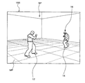
本実施の形態のアクションゲームシステムは、図2に示すように、プレーヤオブジェクト12、敵オブジェクト14、他の敵オブジェクト16と、マップ(床)MPとが配置された仮想3次元オブジェクト空間SPを表示部190に表示させる。そして、プレーヤは、表示部190を見ながら、操作部160を用いてプレーヤオブジェクト12の移動・動作を操作して、所与のプログラムにより移動・動作を行う複数の敵である敵オブジェクト14、他の敵オブジェクト16と格闘を行うゲームを楽しむ。
2-1: Outline of Game As shown in FIG. 2, the action game system of this embodiment is a virtual game in which a
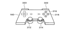
図3には、操作部160の一例が示されている。本実施の形態の操作部160は、プレーヤが両手で操作部160の左右を把持し、操作部160に配置された複数の操作子を左右の手の親指、人差し指、中指で操作可能に形成されている。
FIG. 3 shows an example of the
この操作部160の中央下部には、左レバー312、右レバー314が設けられている。これら左レバー312、右レバー314は、レバー部分を全方向に倒すことができ、レバー部分を倒した量と方向の変化量と変化速度をアナログ的に検出可能に形成されている。そして、本実施の形態では、左レバー312を倒した方向に応じて、プレーヤオブジェクト12をマップ(床)MP上で移動させる。また、右レバー314を倒した方向に応じて、オブジェクト空間SPを撮影する仮想カメラの位置、向きをオブジェクト空間SP内で変化させる。従って、本実施の形態のアクションゲームシステムでは、プレーヤオブジェクト12の位置、回転角度と、仮想カメラの位置、向きをアナログ的(連続的に)に操作することができる。
A
また、操作部160の右側中央部には、ON/OFFを検出可能に形成された4つのボタンが設けられており、本実施の形態では、△ボタン316を押下することによりプレーヤオブジェクト12が所与のオブジェクト(例えば槍や金属バット等)を投げる動作を行い、○ボタン318を押下することによりプレーヤオブジェクト12がパンチやキック等の打撃攻撃動作を行うように形成されている。
In addition, four buttons formed so as to be able to detect ON / OFF are provided in the center on the right side of the
また、操作部160の左右上部には、ON/OFFを検出可能に形成された左ボタン320と右ボタン322が設けられており、本実施の形態では、左ボタン320を押下することによりプレーヤオブジェクト12が投げる対象となる所与のオブジェクトを拾う動作を行うように形成されている。また、右ボタン322を押下することにより、プレーヤオブジェクト12を追従する仮想カメラ制御処理を行うモードと、本実施の形態に特徴的な、移動オブジェクト間の距離に応じた仮想カメラ制御処理を行うモードとを切替えるように形成されている。そして、本実施の形態では、移動オブジェクト間の距離に応じた仮想カメラ制御処理を行うモードが設定されている場合には、右レバー314を倒すことにより、移動オブジェクト間の距離に応じた仮想カメラ制御処理を行う対象であるターゲットオブジェクトを複数の敵オブジェクトから選択することができる。
Further, a
2−2:移動オブジェクト間の距離に応じた仮想カメラ制御処理
本実施の形態では、初期状態では、プレーヤオブジェクト12を追従するように視点位置、視線方向を制御する。そして、本実施の形態の特徴的な処理として、敵オブジェクト14、16から1の敵オブジェクトがターゲットオブジェクトとして選択された場合には、プレーヤオブジェクト12とターゲットオブジェクトとして選択された敵オブジェクトとが、仮想カメラの視野範囲に入るように所定の視点位置、視線方向の制御を行う。
2-2: Virtual Camera Control Processing According to Distance Between Moving Objects In this embodiment, the viewpoint position and the line-of-sight direction are controlled so as to follow the
具体的には、プレーヤキャラクタ12を第1の移動オブジェクトCH1として、選択された敵オブジェクトを第2の移動オブジェクトCH2として設定し、第1の移動オブジェクトCH1と第2の移動オブジェクトCH2との位置が近づくにつれて、第1の移動オブジェクトCH1と仮想カメラとの距離である第1の距離と、第2の移動オブジェクトCH2と仮想カメラとの距離である第2の距離と、の差が小さくなるように仮想カメラの位置を変化させるとともに、第1の移動オブジェクトCH1と第2の移動オブジェクトCH2とを結ぶ方向と、仮想カメラの視線方向と、がなす角が直角に近づくように仮想カメラの向きを変化させる仮想カメラ制御処理を行う。
Specifically, the
また、第1の移動オブジェクトCH1と第2の移動オブジェクトCH2との位置が離れるにつれて、前記第1の距離と前記第2の距離との差が大きくなるように仮想カメラの位置を変化させるとともに、第1の移動オブジェクトCH1と第2の移動オブジェクトCH2とを結ぶ方向と、仮想カメラの視線方向と、がなす角が直角から遠ざかるように仮想カメラの向きを変化させる仮想カメラ制御処理を行う。以下、本実施の形態に特徴的な移動オブジェクト間の距離に応じた仮想カメラ制御処理について説明する。 In addition, as the position of the first moving object CH1 and the second moving object CH2 increases, the position of the virtual camera is changed so that the difference between the first distance and the second distance increases. A virtual camera control process is performed to change the orientation of the virtual camera so that the angle formed by the direction connecting the first moving object CH1 and the second moving object CH2 and the viewing direction of the virtual camera is away from the right angle. Hereinafter, virtual camera control processing according to the distance between moving objects, which is characteristic of the present embodiment, will be described.
図4(A)〜(E)は、第1の移動オブジェクトCH1、第2の移動オブジェクトCH2、視点CMが配置されたオブジェクト空間SPをXZ平面で表現した(真上から見た)図である。なお、第1の移動オブジェクトCH1、第2の移動オブジェクトCH2、視点CMには、それぞれ任意のY座標が与えられている。また、図2、図5〜図8は、視点位置、視線方向が、図4(A)〜(E)にあるときに生成される画像を示す図である。 FIGS. 4A to 4E are diagrams (viewed from directly above) representing the object space SP in which the first moving object CH1, the second moving object CH2, and the viewpoint CM are arranged on the XZ plane. . Arbitrary Y coordinates are given to the first moving object CH1, the second moving object CH2, and the viewpoint CM, respectively. 2 and 5 to 8 are diagrams illustrating images generated when the viewpoint position and the line-of-sight direction are in FIGS. 4 (A) to 4 (E).
まず、ゲーム開始時には初期状態として、図4(A)のように、仮想カメラの注視点EPがプレーヤオブジェクト12に設定されており、図2に示すように、プレーヤオブジェクト12を中心とした画像が生成される。そして、移動オブジェクト間の距離に応じた仮想カメラ制御処理を行うモードが設定されると、図4(B)のように、第1の移動オブジェクトCH1(プレーヤキャラクタ12)と視点CMとの距離である第1の距離d1が、第2の移動オブジェクトCH2(敵キャラクタ14)と視点CMとの距離である第2の距離d2よりも若干小さくなるように、視点CMを連続的に移動させる。そして、仮想カメラの注視点EPを、第1の移動オブジェクトCH1と第2の移動オブジェクトCH2の間に連続的に移動させ、視線方向EDが注視点EPを向くように仮想カメラの向きを制御する。
First, as an initial state at the start of the game, the gazing point EP of the virtual camera is set to the
すると、図5のように、やや第1の移動オブジェクトCH1寄りの横側から、第1の移動オブジェクトCH1と第2の移動オブジェクトCH2の間を中心として見る画像が生成される。なお、第2の移動オブジェクトCH2の頭上のマーク18は、敵オブジェクトが第2の移動オブジェクトCH2として選択されていることを示すためのものである。
Then, as shown in FIG. 5, an image viewed between the first moving object CH1 and the second moving object CH2 as a center is generated from a side slightly closer to the first moving object CH1. The
そして、図4(C)のように、第1の移動オブジェクトCH1の位置と第2の移動オブジェクトCH2の位置とが離れると、第2の距離d2に対する第1の距離d1の比が小さくなるように視点CMの位置を制御し、第1の移動オブジェクトCH1の代表点と第2の移動オブジェクトCH2の代表点とを結ぶ方向CCと、視線方向EDとのなす角が直角から遠ざかるように仮想カメラの向きを制御する。すると、図6のように、第1の移動オブジェクトCH1寄りの斜め後ろ側から、第1の移動オブジェクトCH1と第2の移動オブジェクトCH2の間を中心として見る画像が生成される。 As shown in FIG. 4C, when the position of the first moving object CH1 and the position of the second moving object CH2 are separated, the ratio of the first distance d1 to the second distance d2 is decreased. The virtual camera controls the position of the viewpoint CM so that the angle formed between the direction CC connecting the representative point of the first moving object CH1 and the representative point of the second moving object CH2 and the line-of-sight direction ED is away from the right angle. Control the direction of the. Then, as shown in FIG. 6, an image viewed between the first moving object CH <b> 1 and the second moving object CH <b> 2 as a center is generated from an oblique rear side near the first moving object CH <b> 1.
そして、図4(D)、(E)のように、第1の移動オブジェクトCH1の位置と第2の移動オブジェクトCH2の位置とが更に離れると、第2の距離d2に対する第1の距離d1の比が更に小さくなるように視点CMの位置を制御し、方向CCと視線方向EDとのなす角が直角から更に遠ざかるように仮想カメラの向きを制御する。すると、図4(D)の状態では、図7のように、第1の移動オブジェクトCH1寄りの更に斜め後ろ側から、第1の移動オブジェクトCH1と第2の移動オブジェクトCH2の間を中心として見る画像が生成される。そして、図4(E)の状態では、図8のように、第1の移動オブジェクトCH1のほぼ後ろ側から第2の移動オブジェクトCH2を奥行き方向に見る画像が生成される。 Then, as shown in FIGS. 4D and 4E, when the position of the first moving object CH1 and the position of the second moving object CH2 are further separated, the first distance d1 with respect to the second distance d2 The position of the viewpoint CM is controlled so that the ratio is further reduced, and the direction of the virtual camera is controlled so that the angle formed by the direction CC and the line-of-sight direction ED is further away from the right angle. Then, in the state of FIG. 4D, as shown in FIG. 7, the first moving object CH1 and the second moving object CH2 are viewed from the diagonally rear side near the first moving object CH1 as the center. An image is generated. In the state of FIG. 4E, as shown in FIG. 8, an image is generated in which the second moving object CH2 is viewed in the depth direction from substantially the rear side of the first moving object CH1.
なお、本実施の形態では、図4(E)の状態まで方向CCと視線方向EDとのなす角が直角から遠ざかると、第1の移動オブジェクトCH1の位置と第2の移動オブジェクトCH2の位置とが更に離れても、それ以上方向CCと視線方向EDとのなす角が変化しないように制御する。すなわち、方向CCに対する視線方向EDの角度の最小値が、図中の角度に設定されている。これにより、第1の移動オブジェクトCH1の位置と第2の移動オブジェクトCH2の位置とが更に離れた場合に、第2の移動オブジェクトCH2が第1の移動オブジェクトCH1の陰に隠れて表示されなくなってしまうことを防止することができる。 In the present embodiment, when the angle formed by the direction CC and the line-of-sight direction ED moves away from a right angle until the state shown in FIG. 4E, the position of the first moving object CH1 and the position of the second moving object CH2 Control is performed so that the angle formed by the direction CC and the line-of-sight direction ED does not change even if the distance further increases. That is, the minimum value of the viewing direction ED with respect to the direction CC is set to the angle in the figure. As a result, when the position of the first moving object CH1 and the position of the second moving object CH2 are further away, the second moving object CH2 is hidden behind the first moving object CH1 and is not displayed. Can be prevented.
一方、図4(E)の状態から図4(B)の状態まで、第1の移動オブジェクトCH1の位置と第2の移動オブジェクトCH2の位置とが近づいていくと、第1の距離d1と第2の距離d2との差が小さくなるように視点CMの位置を制御し、方向CCと視線方向EDとのなす角が直角に近づくように仮想カメラの向きを制御する。 On the other hand, when the position of the first moving object CH1 approaches the position of the second moving object CH2 from the state of FIG. 4E to the state of FIG. 4B, the first distance d1 and the second distance The position of the viewpoint CM is controlled so that the difference from the distance d2 of 2 becomes small, and the direction of the virtual camera is controlled so that the angle formed by the direction CC and the line-of-sight direction ED approaches a right angle.
こうして、本実施の形態では、移動オブジェクト間の距離に応じた仮想カメラ制御処理を行うことにより、第1の移動オブジェクトCH1と第2の移動オブジェクトCH2との位置が離れたとしても、第1の移動オブジェクトCH1を画像において大きく表示させることができ、プレーヤが操作可能なプレーヤキャラクタ12の視認性を高め、迫力ある画像を表示させることができる。
Thus, in the present embodiment, even if the positions of the first moving object CH1 and the second moving object CH2 are separated by performing the virtual camera control process according to the distance between the moving objects, The moving object CH1 can be displayed large in the image, the visibility of the
しかも、本実施の形態では、第1の移動オブジェクトCH1と第2の移動オブジェクトCH2との位置が近づくにつれて、第1の移動オブジェクトCH1及び第2の移動オブジェクトCH2の双方の視点CMに対する奥行き方向の距離の差を近づけることにより、第1の移動オブジェクトCH1と第2の移動オブジェクトCH2との間の距離をわかりやすく表示させることができる。特に、本実施の形態のようなアクションゲームシステムにおいては、接近戦となった場合には、プレーヤキャラクタ12と敵キャラクタ14との間合いをわかりやすく表示させることができ、プレーヤが攻撃動作や防御動作のための操作を適切に行うことができる。
Moreover, in the present embodiment, as the positions of the first moving object CH1 and the second moving object CH2 approach, the depth direction relative to the viewpoint CMs of both the first moving object CH1 and the second moving object CH2 is increased. By reducing the difference in distance, the distance between the first moving object CH1 and the second moving object CH2 can be displayed in an easily understandable manner. In particular, in the action game system as in the present embodiment, in the case of a close battle, the
加えて、第1の移動オブジェクトCH1と第2の移動オブジェクトCH2との位置が離れるにつれて、第2の移動オブジェクトCH2の視点CMに対する奥行き方向の距離を遠ざけることにより、第1の移動オブジェクトCH1と第2の移動オブジェクトCH2との位置が離れていることを表現することができる。 In addition, as the position of the first moving object CH1 and the second moving object CH2 increases, the distance between the first moving object CH1 and the second moving object CH2 is increased by increasing the distance in the depth direction from the viewpoint CM of the second moving object CH2. It can be expressed that the position of the second moving object CH2 is separated.
従って、第1の移動オブジェクトCH1と第2の移動オブジェクトCH2との位置が離れた場合に、第1の移動オブジェクトCH1を画像において大きく表示させても、第1の移動オブジェクトCH1及び第2の移動オブジェクトCH2の双方を仮想カメラの視野範囲内に収め、双方のオブジェクトを表示させることができる。 Therefore, even when the first moving object CH1 and the second moving object CH2 are separated from each other, even if the first moving object CH1 is displayed largely in the image, the first moving object CH1 and the second moving object CH1 are displayed. Both objects CH2 can be accommodated within the visual field range of the virtual camera, and both objects can be displayed.
特に、本実施の形態のアクションゲームでは、プレーヤキャラクタ12の位置と敵キャラクタ14の位置とが離れている場合でも、槍や金属バット等の所与のオブジェクトを投げることにより攻撃を行うことができるが、本実施の形態では、このような離れた位置における被投てき体による攻撃動作を、適切にかつ迫力ある画像として表示させることができる。
In particular, in the action game of this embodiment, even when the position of the
なお、第1の移動オブジェクトCH1の位置と第2の移動オブジェクトCH2の位置との距離が所定の距離以下となった場合には、視点CMを、第1の距離d1と第2の距離d2との差がほぼ0となる位置から変化しないように制御し、視線方向EDを、方向CCと視線方向EDとがほぼ直角に交わる方向から変化しないように制御してもよい。 Note that when the distance between the position of the first moving object CH1 and the position of the second moving object CH2 is equal to or less than a predetermined distance, the viewpoint CM is defined as the first distance d1 and the second distance d2. The line-of-sight direction ED may be controlled so as not to change from the direction in which the direction CC and the line-of-sight direction ED intersect at a substantially right angle.
2−3:移動オブジェクト間の距離に応じた仮想カメラ制御処理の具体的手法
以下、図面を用いて、移動オブジェクト間の距離に応じた仮想カメラ制御処理の具体的な処理の一例を説明する。
2-3: Specific Method of Virtual Camera Control Processing According to Distance Between Moving Objects Hereinafter, an example of specific processing of virtual camera control processing according to the distance between moving objects will be described using the drawings.
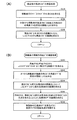
図9は、移動オブジェクト間の距離に応じた仮想カメラ制御処理の概要を示したフローチャートであり、図10(A)、(B)は、図9の処理の詳細を示したフローチャートである。また、図11〜図13は、第1の移動オブジェクトCH1、第2の移動オブジェクトCH2、視点CMが配置されたオブジェクト空間SPをXZ平面で表現した(真上から見た)図であり、第1の移動オブジェクトCH1、第2の移動オブジェクトCH2、視点CMには、それぞれ任意のY座標が与えられている。 FIG. 9 is a flowchart showing an overview of the virtual camera control process according to the distance between moving objects, and FIGS. 10A and 10B are flowcharts showing details of the process of FIG. FIGS. 11 to 13 are views showing the object space SP in which the first moving object CH1, the second moving object CH2, and the viewpoint CM are arranged on the XZ plane (viewed from directly above). An arbitrary Y coordinate is given to each of the first moving object CH1, the second moving object CH2, and the viewpoint CM.
まず、図9のステップS12において、フレーム更新が行われたか否かを判断し、フレーム更新が行われた場合には(ステップS12のY)、ステップS14において、前フレームの視点CMが、第1の移動オブジェクトCH1と第2の移動オブジェクトCH2とを結ぶ方向CCに対していずれの位置にあるかを判定する。 First, in step S12 of FIG. 9, it is determined whether or not the frame has been updated. If the frame has been updated (Y in step S12), the viewpoint CM of the previous frame is the first frame in step S14. It is determined which position is located with respect to the direction CC connecting the moving object CH1 and the second moving object CH2.
具体的には、図11(A)、(B)に示すように、Z軸方向に平行に任意に設定される基準軸Zに対する前フレームの視線方向EDのY軸周りの回転角度θ1と方向CCのY軸周りの回転角度θ2の差θ3が0未満か否かを判定する。例えば、図11(A)のように、θ3<0の場合には、視点CMは、第1の移動オブジェクトCH1を左側に見る位置にある。一方、θ3<0でない場合には、図11(B)のように、視点CMは、第1の移動オブジェクトCH1を右側に見る位置にある。なお、フレームごとに視点CMを保留記憶部に記憶しておき、これを参照することにより前フレームの視点CMがいずれの位置にあるか判定してもよい。 Specifically, as shown in FIGS. 11A and 11B, the rotation angle θ1 and the direction around the Y axis of the line-of-sight direction ED of the previous frame with respect to the reference axis Z arbitrarily set in parallel to the Z-axis direction. It is determined whether or not the difference θ3 in the rotation angle θ2 around the Y axis of CC is less than zero. For example, as shown in FIG. 11A, when θ3 <0, the viewpoint CM is at a position where the first moving object CH1 is seen on the left side. On the other hand, when θ3 <0 is not satisfied, the viewpoint CM is at a position where the first moving object CH1 is viewed to the right as shown in FIG. Note that the viewpoint CM may be stored in the holding storage unit for each frame, and the position of the viewpoint CM of the previous frame may be determined by referring to the viewpoint CM.
そして、ステップS16において、前フレームの第1の移動オブジェクトCH1の位置座標CH1と第2の移動オブジェクトCH2の位置座標CH2の移動演算を行い、移動後の第1の移動オブジェクトCH1´の位置座標CH1´(x1、z1)と第2の移動オブジェクトCH2´の位置座標CH2´(x2、z2)を求める。すると、ステップS18において、移動後の視点CM´の位置を求める演算処理を行い、ステップS20において、移動後の視線方向ED´を求める演算処理を行う。 In step S16, the movement calculation of the position coordinate CH1 of the first moving object CH1 and the position coordinate CH2 of the second moving object CH2 in the previous frame is performed, and the position coordinate CH1 of the first moving object CH1 ′ after the movement is calculated. '(X1, z1) and the position coordinate CH2' (x2, z2) of the second moving object CH2 'are obtained. Then, in step S18, a calculation process for obtaining the position of the viewpoint CM ′ after movement is performed, and in step S20, a calculation process for obtaining the line-of-sight direction ED ′ after movement is performed.
なお、ステップS18とステップS20で行う演算処理は、本実施の形態では、所定の関数を用いて行われる。ここで、所定の関数は2種類用意されており、ステップS14で判定した前フレームの視点CMの位置に応じた関数を用いて、それぞれの演算処理を行う。 In the present embodiment, the arithmetic processing performed in step S18 and step S20 is performed using a predetermined function. Here, two types of predetermined functions are prepared, and each calculation process is performed using a function corresponding to the position of the viewpoint CM of the previous frame determined in step S14.
そして、ステップS22において、移動後の第1の移動オブジェクトCH1´と第2の移動オブジェクトCH2´とを、移動後の視点CM´、視線方向ED´により撮影した現在フレームの画像を描画する処理を行う。 Then, in step S22, a process of drawing an image of the current frame obtained by capturing the first moving object CH1 ′ and the second moving object CH2 ′ after the movement with the viewpoint CM ′ and the line-of-sight direction ED ′ after the movement. Do.
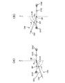
図10(A)には、移動後の視点CM´を求める演算処理の詳細のフローチャートが示されている。本実施の形態では、まず、ステップS24において、移動後のCH1´(x1、z1)とCH2´(x2、z2)の中点CE(x3、z3)を求める。そして、ステップS26において、中点CE(x3、z3)と移動後の視点CM´(cx、cz)とを結ぶ方向DD0の、基準軸Zに対するY軸周りの回転角度θ4を、所定の関数により求める。 FIG. 10A shows a detailed flowchart of the calculation process for obtaining the viewpoint CM ′ after movement. In the present embodiment, first, in step S24, the midpoint CE (x3, z3) of CH1 ′ (x1, z1) and CH2 ′ (x2, z2) after movement is obtained. In step S26, the rotation angle θ4 around the Y axis with respect to the reference axis Z in the direction DD0 connecting the midpoint CE (x3, z3) and the moved viewpoint CM ′ (cx, cz) is determined by a predetermined function. Ask.
本実施の形態では、Y軸周りの回転角度90°=0.25、移動後の第1の移動オブジェクトCH1´と第2の移動オブジェクトCH2´との距離=L1、所定の係数=A、L2=L1/Aとして、図9のステップS14においてθ3<0と判定された場合には、下記の式A1を用いて、図12(A)のようにしてθ4を求める。 In the present embodiment, the rotation angle around the Y axis is 90 ° = 0.25, the distance between the first moving object CH1 ′ and the second moving object CH2 ′ after movement is L1, and the predetermined coefficients are A and L2. = L1 / A, and if θ3 <0 is determined in step S14 of FIG. 9, θ4 is obtained as shown in FIG. 12A by using the following formula A1.
θ4=θ2+0.25−L2・・・・・・・(式A1)
なお、値Aは、L1/A<0.25となる値であり、Aの値が大きくなればなるほど、L1の変化に対する変化率が小さくなり、第1の移動オブジェクトCH1と第2の移動オブジェクトCH2との距離の変化に対して視点CMが相対的にゆっくりと変化することとなる。また、L2には所定の最大値が設定されており、方向CCに対する視線方向EDの角度の最小値が図4(E)の角度となる値が設定されている。
θ4 = θ2 + 0.25−L2 (formula A1)
The value A is a value satisfying L1 / A <0.25. The larger the value of A, the smaller the rate of change with respect to the change in L1, and the first moving object CH1 and the second moving object. The viewpoint CM changes relatively slowly with respect to the change in the distance to CH2. In addition, a predetermined maximum value is set for L2, and a value is set such that the minimum value of the angle of the line-of-sight direction ED with respect to the direction CC is the angle shown in FIG.
そして、ステップS28において、視点CM´と中点CEとの距離をL3とし、θ4とL3とから移動後の視点CM´(cx、cz)を求める。本実施の形態では、L3=L1×B+Cとして、下記の式A2、A3を用いて求める。 In step S28, the distance between the viewpoint CM ′ and the midpoint CE is set to L3, and the moved viewpoint CM ′ (cx, cz) is obtained from θ4 and L3. In the present embodiment, L3 = L1 × B + C is obtained using the following formulas A2 and A3.
cx=x3−sin(θ4)×L3・・・・(式A2)
cz=z3−cos(θ4)×L3・・・・(式A3)
なお、値Bと値Cは、移動後の仮想カメラの視野範囲に、第1の移動オブジェクトCH1と第2の移動オブジェクトCH2とが入り、かつ、第1の移動オブジェクトCH1と第2の移動オブジェクトCH2を最適な大きさで表示させる任意の値とすることができる。また、L3には所定の最大値が設定されており、L1が大きくなったときでも、視点CM´が第1の移動オブジェクトCH1から離れすぎないようにする値が設定されている。
cx = x3-sin (θ4) × L3 (Expression A2)
cz = z3-cos (θ4) × L3 (formula A3)
Note that the values B and C are the first moving object CH1 and the second moving object CH2 in the visual field range of the moved virtual camera, and the first moving object CH1 and the second moving object. It is possible to set an arbitrary value for displaying CH2 in an optimum size. In addition, a predetermined maximum value is set in L3, and a value is set so that the viewpoint CM ′ is not too far from the first moving object CH1 even when L1 becomes large.
一方、図9のステップS14において、θ3<0でないと判定された場合には、下記の式B1を用いて、図12(B)のようにしてθ4を求める。 On the other hand, if it is determined in step S14 of FIG. 9 that θ3 <0 is not satisfied, θ4 is obtained as shown in FIG.
θ4=θ2−0.25+L2・・・・・・・(式B1)
また、移動後の視点CM´(cx、cz)を、下記の式B2、B3
cx=x3−sin(θ4)×L3・・・・(式B2)
cz=z3+cos(θ4)×L3・・・・(式B3)
を用いて求める。
θ4 = θ2−0.25 + L2 (Equation B1)
Further, the viewpoint CM ′ (cx, cz) after movement is expressed by the following equations B2, B3.
cx = x3-sin (θ4) × L3 (formula B2)
cz = z3 + cos (θ4) × L3 (formula B3)
Find using.
図10(B)には、移動後の視線方向ED´を求める演算処理の詳細のフローチャートが示されている。ここでは、図12(A)で示した、式A2、A3により求められた移動後の視点CM´についての視線方向ED´を求める例を挙げて説明する。 FIG. 10B shows a detailed flowchart of the calculation process for obtaining the line-of-sight direction ED ′ after movement. Here, an example in which the line-of-sight direction ED ′ is obtained for the viewpoint CM ′ after movement obtained by the expressions A2 and A3 shown in FIG.
本実施の形態では、まず、ステップS30において、図13(A)のように、視点CM´(cx、cz)とCH1´(x1、z1)とを結ぶ方向DD1の基準軸Zに対するY軸周りの回転角度θ5と、視点CM´(cx、cz)とCH2´(x2´、z2´)とを結ぶ方向DD2の基準軸Zに対するY軸周りの回転角度θ6とから、∠CH1´CM´CH2´を二等分する角度θ7を、θ7=(θ6−θ5)/2のようにして求め、ステップS32において、移動後の視線方向ED´の基準軸Zに対するY軸周りの回転角度θ7´を所定の関数式C1を用いて求める。 In this embodiment, first, in step S30, as shown in FIG. 13A, around the Y axis with respect to the reference axis Z in the direction DD1 connecting the viewpoints CM ′ (cx, cz) and CH1 ′ (x1, z1). And the rotation angle θ6 around the Y axis with respect to the reference axis Z in the direction DD2 connecting the viewpoints CM ′ (cx, cz) and CH2 ′ (x2 ′, z2 ′), ∠CH1′CM′CH2 An angle θ7 that bisects ′ is obtained as θ7 = (θ6-θ5) / 2, and in step S32, a rotation angle θ7 ′ around the Y axis with respect to the reference axis Z in the line-of-sight direction ED ′ after movement is obtained. It is determined using a predetermined function formula C1.
θ7´=θ7×D+θ5・・・・・・・・・(式C1)
なお、値Dは、移動後の視線方向ED´を∠CH1´CM´CH2´の二等分線に沿う方向DVよりも若干第1の移動オブジェクトCH1寄りにして、第1の移動オブジェクトCH1´を中央寄りに表示させる任意の値とすることができる。
θ7 ′ = θ7 × D + θ5 (formula C1)
Note that the value D is set so that the line-of-sight direction ED ′ after movement is slightly closer to the first moving object CH1 than the direction DV along the bisector of ∠CH1′CM′CH2 ′. Can be set to any value that is displayed closer to the center.
すると、ステップS34において、図面13(B)のように、視点CM´と仮の注視点IEとの距離をL3とし、θ7´とL3とから仮の注視点IE(x4、z4)を求める。本実施の形態では、L3=L1×B+Cとして、下記の式C2、C3
x4=cx+sin(θ7´)×L3・・・(式C2)
z4=cz+cos(θ7´)×L3・・・(式C3)
を用いて求める。
Then, in step S34, as shown in FIG. 13B, the distance between the viewpoint CM ′ and the temporary gaze point IE is set to L3, and the temporary gaze point IE (x4, z4) is obtained from θ7 ′ and L3. In this embodiment, L3 = L1 × B + C, and the following formulas C2 and C3
x4 = cx + sin (θ7 ′) × L3 (formula C2)
z4 = cz + cos (θ7 ′) × L3 (formula C3)
Find using.
そして、ステップS36において、方向CCと、視点CM´と仮の注視点IEとを結ぶ方向ED´との交点を求めることにより、移動後の注視点EP´の座標(ix、iz)を求める。 Then, in step S36, the coordinates (ix, iz) of the moved gazing point EP ′ are obtained by obtaining the intersection of the direction CC and the direction ED ′ connecting the viewpoint CM ′ and the temporary gazing point IE.
本実施の形態では、CH1´とCH2´の座標が同じ場合には、下記の式D1、D2
ix=x1 ・・・(式D1)
iz=(z4−cz)×(ix−cx)/(x4−cx)+cz・・(式D2)
を用いて求める。
In the present embodiment, when the coordinates of CH1 ′ and CH2 ′ are the same, the following equations D1 and D2
ix = x1 (Formula D1)
iz = (z4-cz) * (ix-cx) / (x4-cx) + cz .. (formula D2)
Find using.
また、x4=cxの場合には、下記の式E1、E2
ix=x4 ・・・(式E1)
iz=(z2−z1)×(ix−x1)/(x2−x1)+z1・・(式E2)
を用いて求める。
When x4 = cx, the following equations E1, E2
ix = x4 (formula E1)
iz = (z2−z1) × (ix−x1) / (x2−x1) + z1 (Equation E2)
Find using.
また、その他の場合には、下記の式F1、F2
ix={(z2−z1)×x1/(x2−x1)−(x4−cz)×cx/(x4−cx)+cz−z1}/{(z2−z1)/(x2−x1)−(z4−cz)/(x4−cx)} ・・・(式F1)
iz=(z2−z1)×(ix−x1)/(x2−x1)+z1・・(式F2)
を用いて求める。
In other cases, the following formulas F1 and F2
ix = {(z2-z1) * x1 / (x2-x1)-(x4-cz) * cx / (x4-cx) + cz-z1} / {(z2-z1) / (x2-x1)-(z4 -Cz) / (x4-cx)} (Formula F1)
iz = (z2-z1) * (ix-x1) / (x2-x1) + z1 (Formula F2)
Find using.
そして、ステップS38において、移動後の注視点EP´(ix、iz)を見るように仮想カメラの回転角度を制御する。 In step S38, the rotation angle of the virtual camera is controlled so that the watch point EP ′ (ix, iz) after the movement is viewed.
こうして、図13(B)に示すように、第2の移動オブジェクトCH2が第1の移動オブジェクトCH1に対して、CH2の位置からCH2´の位置まで離れると、仮想カメラの位置をCMからCM´に移動させ、注視点をEPからEP´に移動させる。そして、視線方向をEDからED´に変化させる。一方、第2の移動オブジェクトCH2が第1の移動オブジェクトCH1に対して、CH2´の位置からCH2の位置まで近づくと、仮想カメラの位置をCM´からCMに移動させ、注視点をEP´からEPに移動させる。そして、視線方向をED´からEDに変化させる。 Thus, as shown in FIG. 13B, when the second moving object CH2 moves away from the position of CH2 to the position of CH2 ′ with respect to the first moving object CH1, the position of the virtual camera is changed from CM to CM ′. And the point of sight is moved from EP to EP ′. Then, the line-of-sight direction is changed from ED to ED ′. On the other hand, when the second moving object CH2 approaches the first moving object CH1 from the position of CH2 ′ to the position of CH2, the position of the virtual camera is moved from CM ′ to CM, and the gazing point is changed from EP ′. Move to EP. Then, the line-of-sight direction is changed from ED ′ to ED.
このように、本実施の形態では、予め設定された関数により、1フレームごとに第1の移動オブジェクトCH1と第2の移動オブジェクトCH2との距離に応じた適切な視点位置、視線方向を演算することができる。 As described above, in the present embodiment, an appropriate viewpoint position and line-of-sight direction corresponding to the distance between the first moving object CH1 and the second moving object CH2 are calculated for each frame using a preset function. be able to.
なお、移動オブジェクト間の距離に応じた仮想カメラ制御処理は、上記手法以外の手法によっても実現することができる。例えば、移動後の注視点EP´を求める際には、仮の注視点IEを設定せずに、図10(B)のステップS32で求めた移動後の視線方向ED´の角度θ7´から視線方向ED´に沿う線の方程式を求め、方向CCに沿う線の方程式から交点座標を求めることにより移動後の注視点EP´を求めてもよい。 Note that the virtual camera control process according to the distance between moving objects can also be realized by a method other than the above method. For example, when determining the gazing point EP ′ after movement, the temporary gazing point IE is not set, and the line of sight is viewed from the angle θ7 ′ of the line-of-sight direction ED ′ after movement obtained in step S32 of FIG. The gazing point EP ′ after the movement may be obtained by obtaining an equation of a line along the direction ED ′ and obtaining an intersection coordinate from the equation of the line along the direction CC.
また、第1の移動オブジェクトCH1及び第2の移動オブジェクトCH2の少なくとも一方に設定された属性データに基づき、上記関数の係数を変更するようにしてもよい。この場合には、移動オブジェクトに設定された属性データに応じて、視点、視線方向の移動速度、移動軌跡等の移動態様を変化させることができる。従って、移動オブジェクトに設定された属性データに応じた種々の画像を生成することができる。 Further, the coefficient of the function may be changed based on attribute data set in at least one of the first moving object CH1 and the second moving object CH2. In this case, according to the attribute data set for the moving object, the movement mode such as the viewpoint, the moving speed in the line-of-sight direction, and the moving locus can be changed. Therefore, various images can be generated according to the attribute data set for the moving object.
ここで、属性データは、記憶部170の属性データ記憶部173に各キャラクタの属性データ、各アイテムの属性データとして記憶され、ゲーム演算処理部116がゲーム状況に応じた属性データを読み出し、移動オブジェクトごとに設定する処理を行う。
Here, the attribute data is stored in the attribute
2−4:複数の移動オブジェクトとの間の距離に応じた仮想カメラ制御処理
また、本実施の形態では、移動オブジェクト間の距離に応じた仮想カメラ制御処理を行うモードが設定されている場合には、操作部160の右レバー314を倒すことにより、移動オブジェクト間の距離に応じた仮想カメラ制御処理を行う対象であるターゲットオブジェクトを複数の敵オブジェクトから選択することができる。そして、他の敵オブジェクトがターゲットオブジェクトとして選択された場合には、選択された他の敵オブジェクトを第2の移動オブジェクトとして変更設定し、第1の移動オブジェクトと変更後の第2の移動オブジェクトとの距離に応じた仮想カメラ制御処理を行う。
2-4: Virtual camera control processing according to the distance between a plurality of moving objects Also, in the present embodiment, when the mode for performing the virtual camera control processing according to the distance between the moving objects is set. By selecting the
図14は、複数の移動オブジェクトとの間の距離に応じた仮想カメラ制御処理の処理の流れを示すフローチャートである。また、図15は、プレーヤオブジェクト12、敵オブジェクト14、敵オブジェクト16、視点CMが配置されたオブジェクト空間SPをXZ平面で表現した(真上から見た)図である。
FIG. 14 is a flowchart showing the flow of the virtual camera control process according to the distance between a plurality of moving objects. FIG. 15 shows the object space SP in which the
まず、ステップS58において、図15のように、敵オブジェクト14が第2の移動オブジェクトCH2として設定されている場合には、視点の位置をCM1、注視点をEP1として移動オブジェクト間の距離に応じた仮想カメラ制御処理を行う。すると、ステップS60において、ターゲットオブジェクトが変更されたか否かを判断する。ここで、ターゲットオブジェクトが変更されたと判断した場合には(ステップS60のY)、ステップS62において、変更後の敵オブジェクト16を第2の移動オブジェクトCH2´として設定する。
First, in step S58, when the
そして、ステップS64において、第1の移動オブジェクトCH1の位置と変更後の第2の移動オブジェクトCH2´の位置とに基づき、所定の関数により、ターゲットオブジェクト変更後の視点CM2とターゲットオブジェクト変更後の注視点EP2とを求める。すると、ステップS66において、視点の位置を、敵キャラクタ14との距離に応じたCM1から、敵キャラクタ16との距離に応じたCM2に連続的に変更させる。そして、仮想カメラの注視点を、敵キャラクタ14との距離に応じたEP1から、敵キャラクタ16との距離に応じたEP2に連続的に変更させる。そして、ステップS68において、プレーヤオブジェクト12(第1の移動オブジェクトCH1)と敵オブジェクト16(第2の移動オブジェクトCH2´)との間の距離に応じた仮想カメラ制御処理を行う。
In step S64, based on the position of the first moving object CH1 and the changed position of the second moving object CH2 ′, the viewpoint CM2 after the change of the target object and the note after the change of the target object are determined by a predetermined function. The viewpoint EP2 is obtained. Then, in step S66, the position of the viewpoint is continuously changed from CM1 corresponding to the distance to the
このように、本実施の形態では、第2の移動オブジェクトとして設定されている敵オブジェクトが、他の敵オブジェクトに変更された場合には、変更後の敵オブジェクトとの位置に応じた視点位置の制御を自動的に行うことができる。なお、ターゲットオブジェクトの選択は、所与のプログラムに基づいて1の移動オブジェクトを自動的に選択してもよい。この場合、プレーヤオブジェクトと複数の敵オブジェクトとの距離を判定し、最も近い敵オブジェクトをターゲットオブジェクトとして選択し、移動オブジェクト間の距離に応じた仮想カメラ制御処理を行うように構成してもよい。 Thus, in this embodiment, when the enemy object set as the second moving object is changed to another enemy object, the viewpoint position corresponding to the position with the changed enemy object is changed. Control can be performed automatically. In selecting the target object, one moving object may be automatically selected based on a given program. In this case, the distance between the player object and a plurality of enemy objects may be determined, the closest enemy object may be selected as the target object, and virtual camera control processing may be performed according to the distance between the moving objects.
なお、ステップS64において、第1の移動オブジェクトCH1の位置と変更後の第2の移動オブジェクトCH2´の位置とに基づき、所定の関数により、ターゲットオブジェクト変更後の視点として、図中のCM3を求めるようにしてもよい。この場合には、ステップS66において、視点の位置を、敵キャラクタ14との距離に応じたCM1から、敵キャラクタ16との距離に応じたCM3に連続的に変更させればよい。
In step S64, CM3 in the figure is obtained as a viewpoint after changing the target object by a predetermined function based on the position of the first moving object CH1 and the position of the second moving object CH2 ′ after the change. You may do it. In this case, in step S66, the viewpoint position may be continuously changed from CM1 corresponding to the distance to the
3.他の実施の形態
また、本発明を適用することができる他の実施の形態として、第1の移動オブジェクトの位置と第2の移動オブジェクトの位置との距離にかかわらず、第1の視点位置変更条件又は第2の視点位置変更条件のいずれかが満たされたか否かを判定し、仮想カメラ制御部114が、第1の視点位置変更条件が満たされた場合に、第1の移動オブジェクトと仮想カメラとの距離である第1の距離と、第2の移動オブジェクトと仮想カメラとの距離である第2の距離と、の差が小さくなるように視点の位置を変化させ、第2の視点位置変更条件が満たされた場合に、第1の距離と第2の距離との差が大きくなるように視点の位置を変化させるように構成してもよい。
3. Other Embodiments As another embodiment to which the present invention can be applied, the first viewpoint position change is performed regardless of the distance between the position of the first moving object and the position of the second moving object. It is determined whether either the condition or the second viewpoint position change condition is satisfied, and the virtual
この実施の形態では、例えば、サッカーゲームを例に挙げると、ボールを第1の移動オブジェクトCH1として設定し、プレーヤキャラクタを第2の移動オブジェクトCH2として設定することができる。そして、図16(A)のように、プレーヤキャラクタ20がボール22をキープしていると条件判定部118が判定した場合、すなわち、第1の視点位置変更条件が満たされた場合には、第1の距離d1と第2の距離d2との差が小さくなるように、視点CMをCM1の位置に設定する。そして、注視点EP1を第1の移動オブジェクトCH1と第2の移動オブジェクトCH2とを結ぶ線分CCの中点付近に設定する。すると、ボール22をキープしているプレーヤキャラクタ20を横方向から見る画像を描画することができる。
In this embodiment, for example, taking a soccer game as an example, the ball can be set as the first moving object CH1, and the player character can be set as the second moving object CH2. Then, as shown in FIG. 16A, when the
一方、図16(B)のように、プレーヤキャラクタ20がボール22をキープしていないと条件判定部118が判定した場合、すなわち、第2の視点位置変更条件が満たされた場合には、第1の距離d1に対する第2の距離d2の比が小さくなるように、視点CMをCM2に設定し、CM1からCM2に連続的に移動させる。そして、注視点を、線分CC上であって、線分CCの中点よりも第2の移動オブジェクトCH2よりのEP2に設定し、EP1からEP2に連続的に移動させる。すると、ボール22をキープしていないプレーヤキャラクタ20のほぼ後ろ側から、プレーヤキャラクタ20を手前側に大きく見て、ボール22を奥行き方向に見る画像を描画することができる。
On the other hand, as shown in FIG. 16B, when the
また、この実施の形態においても、第1の移動オブジェクトCH1(ボール)を除くN−1個の移動オブジェクト(プレーヤキャラクタ)から1の移動オブジェクトを選択可能に構成し、仮想カメラ制御部114が、選択された移動オブジェクトを第2の移動オブジェクトCH2として、視点位置を変化させるようにしてもよい。この場合には、11人のプレーヤキャラクタの中から、操作部160により操作を行う1のプレーヤキャラクタをプレーヤが選択し、選択したプレーヤキャラクタがボール22をキープしているか否かにより、視点位置、視線方向の制御を行う。
Also in this embodiment, one moving object can be selected from N-1 moving objects (player characters) excluding the first moving object CH1 (ball), and the virtual
こうして、この実施の形態によれば、プレーヤキャラクタ20がボール22をキープしている場合に、ボール22及びプレーヤキャラクタ20を横方向から見た画像を表示させることができ、例えば、プレーヤキャラクタ20がボール22をキープする様子をわかりやすく表示させることができる。また、プレーヤキャラクタ20がボール22をキープしていない場合でも、プレーヤが選択したプレーヤキャラクタ20を手前側に大きく表示させつつ奥行き方向にボール22を表示させることができ、例えば、奥行き方向から飛んでくるロングパスを受け取る様子を迫力のある画像として表示させることができる。
Thus, according to this embodiment, when the
4.ハードウェア構成
図17に本実施形態を実現できるハードウェア構成の例を示す。メインプロセッサ900は、CD982(情報記憶媒体)に格納されたプログラム、通信インターフェース990を介してダウンロードされたプログラム、或いはROM950に格納されたプログラムなどに基づき動作し、ゲーム処理、画像処理、音処理などを実行する。コプロセッサ902は、メインプロセッサ900の処理を補助するものであり、マトリクス演算(ベクトル演算)を高速に実行する。例えばオブジェクトを移動させたり動作(モーション)させる物理シミュレーションに、マトリクス演算処理が必要な場合には、メインプロセッサ900上で動作するプログラムが、その処理をコプロセッサ902に指示(依頼)する。
4). Hardware Configuration FIG. 17 shows an example of a hardware configuration capable of realizing this embodiment. The
ジオメトリプロセッサ904は、メインプロセッサ900上で動作するプログラムからの指示に基づいて、座標変換、透視変換、光源計算、曲面生成などのジオメトリ処理を行うものであり、マトリクス演算を高速に実行する。データ伸張プロセッサ906は、圧縮された画像データや音データのデコード処理を行ったり、メインプロセッサ900のデコード処理をアクセレートする。これにより、オープニング画面やゲーム画面において、MPEG方式等で圧縮された動画像を表示できる。
The
描画プロセッサ910は、ポリゴンや曲面などのプリミティブ面で構成されるオブジェクトの描画(レンダリング)処理を実行する。オブジェクトの描画の際には、メインプロセッサ900は、DMAコントローラ970を利用して、描画データを描画プロセッサ910に渡すと共に、必要であればテクスチャ記憶部924にテクスチャを転送する。すると描画プロセッサ910は、描画データやテクスチャに基づいて、Zバッファなどを利用した隠面消去を行いながら、オブジェクトをフレームバッファ922に描画する。また描画プロセッサ910は、αブレンディング(半透明処理)、デプスキューイング、ミップマッピング、フォグ処理、バイリニア・フィルタリング、トライリニア・フィルタリング、アンチエリアシング、シェーディング処理なども行う。1フレーム分の画像がフレームバッファ922に書き込まれるとその画像はディスプレイ912に表示される。
The drawing
サウンドプロセッサ930は、多チャンネルのADPCM音源などを内蔵し、BGM、効果音、音声などのゲーム音を生成し、スピーカ932を介して出力する。ゲームコントローラ942やメモリカード944からのデータはシリアルインターフェース940を介して入力される。
The
ROM950にはシステムプログラムなどが格納される。業務用ゲームシステムの場合にはROM950が情報記憶媒体として機能し、ROM950に各種プログラムが格納される。なおROM950の代わりにハードディスクを利用してもよい。RAM960は各種プロセッサの作業領域となる。DMAコントローラ970は、プロセッサ、メモリ間でのDMA転送を制御する。CDドライブ980は、プログラム、画像データ、或いは音データなどが格納されるCD982にアクセスする。通信インターフェース990はネットワーク(通信回線、高速シリアルバス)を介して外部との間でデータ転送を行う。
The
なお本実施形態の各部(各手段)の処理は、その全てをハードウェアのみにより実現してもよいし、情報記憶媒体に格納されるプログラムや通信インターフェースを介して配信されるプログラムにより実現してもよい。或いは、ハードウェアとプログラムの両方により実現してもよい。 The processing of each unit (each unit) in this embodiment may be realized entirely by hardware, or may be realized by a program stored in an information storage medium or a program distributed via a communication interface. Also good. Alternatively, it may be realized by both hardware and a program.
そして本実施形態の各部の処理をハードウェアとプログラムの両方により実現する場合には、情報記憶媒体には、ハードウェア(コンピュータ)を本実施形態の各部として機能させるためのプログラムが格納される。より具体的には、上記プログラムが、ハードウェアである各プロセッサ902、904、906、910、930に処理を指示すると共に、必要であればデータを渡す。そして、各プロセッサ902、904、906、910、930は、その指示と渡されたデータとに基づいて本発明の各部の処理を実現する。
When the processing of each part of this embodiment is realized by both hardware and a program, a program for causing the hardware (computer) to function as each part of this embodiment is stored in the information storage medium. More specifically, the program instructs the
なお本発明は、上記実施形態で説明したものに限らず、種々の変形実施が可能である。例えば、明細書又は図面中の記載において広義や同義な用語(描画領域、ピクセル値、変換テーブル等)として引用された用語(フレームバッファ・ワークバッファ、α値、ルックアップテーブル等)は、明細書又は図面中の他の記載においても広義や同義な用語に置き換えることができる。 The present invention is not limited to that described in the above embodiment, and various modifications can be made. For example, terms (frame buffer / work buffer, α value, lookup table, etc.) cited as broad or synonymous terms (drawing area, pixel value, conversion table, etc.) in the description or drawings are not Alternatively, in other descriptions in the drawings, terms can be replaced with terms having a broad meaning or the same meaning.
また本発明は種々のゲームに適用できる。また本発明は、業務用ゲームシステム、家庭用ゲームシステム、多数のプレーヤが参加する大型アトラクションシステム、シミュレータ、マルチメディア端末、ゲーム画像を生成するシステムボード、携帯電話等の種々の画像生成システムに適用できる。 The present invention can be applied to various games. Further, the present invention is applied to various image generation systems such as a business game system, a home game system, a large attraction system in which a large number of players participate, a simulator, a multimedia terminal, a system board for generating a game image, and a mobile phone. it can.
CM 視点
ED 視線方向
EP 注視点
CH1 第1の移動オブジェクト
CH2 第2の移動オブジェクト
d1 第1の距離
d2 第2の距離
100 処理部
110 オブジェクト空間設定部
112 移動・動作処理部
114 仮想カメラ制御部
120 描画部
160 操作部
170 記憶部
180 情報記憶媒体
190 表示部
CM viewpoint ED line-of-sight direction EP gazing point CH1 first moving object CH2 second moving object d1 first distance d2
Claims (16)
第1〜第N(N≧3)のキャラクタオブジェクトをオブジェクト空間に設定するオブジェクト空間設定部と、
記憶部に記憶されたモーションデータに基づいて、第1〜第Nのキャラクタオブジェクトの移動及び動作の少なくとも一方を演算する移動・動作処理部と、
第1のキャラクタオブジェクトを除くN−1のキャラクタオブジェクトから1のキャラクタオブジェクトを第2のキャラクタオブジェクトとして設定するオブジェクト選択部と、
第1のキャラクタオブジェクト及び第2のキャラクタオブジェクトの位置情報に基づいて、仮想カメラの位置、向き、画角の少なくとも1つの制御を行う仮想カメラ制御部と、
オブジェクト空間を仮想カメラから見た画像を生成する画像生成部として、
コンピュータを機能させ、
前記仮想カメラ制御部が、
第1のキャラクタオブジェクトの位置と第2のキャラクタオブジェクトの位置とが近づくにつれて、第1のキャラクタオブジェクトと仮想カメラとの距離である第1の距離と、第2のキャラクタオブジェクトと仮想カメラとの距離である第2の距離と、の差が小さくなるように仮想カメラの位置を変化させ、
第1のキャラクタオブジェクトの位置と第2のキャラクタオブジェクトの位置とが離れるにつれて、前記第1の距離と前記第2の距離との差が大きくなるように仮想カメラの位置を変化させ、
前記オブジェクト選択部が、
操作部からの入力信号に基づき、前記第2のキャラクタオブジェクトとして設定されたキャラクタオブジェクトを除くN−2のキャラクタオブジェクトから1のキャラクタオブジェクトを第2のキャラクタオブジェクトとして変更設定し、
前記画像生成部が、
前記第2のキャラクタオブジェクトとして選択されたキャラクタオブジェクトに対応する位置に、該キャラクタオブジェクトが前記第2のキャラクタオブジェクトとして選択されていることを示すためのマークを表示させることを特徴とするプログラム。 A program for generating a game image of a game in which a plurality of character objects attack each other,
An object space setting unit for setting the first to Nth (N ≧ 3) character objects in the object space;
A movement / motion processing unit that calculates at least one of movement and motion of the first to Nth character objects based on the motion data stored in the storage unit;
An object selection unit for setting one character object as a second character object from N-1 character objects excluding the first character object;
A virtual camera control unit that controls at least one of the position, orientation, and angle of view of the virtual camera based on the position information of the first character object and the second character object;
As an image generator that generates an image of the object space viewed from a virtual camera,
Make the computer work,
The virtual camera control unit is
As the position of the first character object and the position of the second character object approach, the first distance that is the distance between the first character object and the virtual camera, and the distance between the second character object and the virtual camera Change the position of the virtual camera so that the difference between the second distance and
As the position of the first character object and the position of the second character object are separated, the position of the virtual camera is changed so that the difference between the first distance and the second distance increases.
The object selection unit is
Based on an input signal from the operation unit, one character object is changed and set as a second character object from N-2 character objects excluding the character object set as the second character object ,
The image generator
A program for displaying a mark for indicating that the character object is selected as the second character object at a position corresponding to the character object selected as the second character object .
前記仮想カメラ制御部が、
第1のキャラクタオブジェクトの位置と第2のキャラクタオブジェクトの位置とが近づくにつれて、第1のキャラクタオブジェクトと第2のキャラクタオブジェクトとを結ぶ方向と、仮想カメラの視線方向とのなす角が直角に近づくように仮想カメラの向きを変化させ、
第1のキャラクタオブジェクトの位置と第2のキャラクタオブジェクトの位置とが離れるにつれて、第1のキャラクタオブジェクトと第2のキャラクタオブジェクトとを結ぶ方向と、仮想カメラの視線方向とのなす角が直角から遠ざかるように仮想カメラの向きを変化させることを特徴とするプログラム。 In claim 1,
The virtual camera control unit is
As the position of the first character object and the position of the second character object approach, the angle formed between the direction connecting the first character object and the second character object and the line-of-sight direction of the virtual camera approaches a right angle. Change the orientation of the virtual camera so that
As the position of the first character object and the position of the second character object are separated, the angle formed between the direction connecting the first character object and the second character object and the line-of-sight direction of the virtual camera is moved away from the right angle. A program characterized by changing the orientation of the virtual camera.
第1〜第N(N≧3)のキャラクタオブジェクトをオブジェクト空間に設定するオブジェクト空間設定部と、
記憶部に記憶されたモーションデータに基づいて、第1〜第Nのキャラクタオブジェクトの移動及び動作の少なくとも一方を演算する移動・動作処理部と、
第1のキャラクタオブジェクトを除くN−1のキャラクタオブジェクトから1のキャラクタオブジェクトを第2のキャラクタオブジェクトとして設定するオブジェクト選択部と、
第1のキャラクタオブジェクト及び第2のキャラクタオブジェクトの位置情報に基づいて、仮想カメラの位置、向き、画角の少なくとも1つの制御を行う仮想カメラ制御部と、
オブジェクト空間を仮想カメラから見た画像を生成する画像生成部として、
コンピュータを機能させ、
前記仮想カメラ制御部が、
第1のキャラクタオブジェクトの位置と第2のキャラクタオブジェクトの位置とが近づくにつれて、第1のキャラクタオブジェクトと仮想カメラとの距離である第1の距離と、第2のキャラクタオブジェクトと仮想カメラとの距離である第2の距離と、の差が小さくなるように仮想カメラの位置を変化させ、
前記オブジェクト選択部が、
操作部からの入力信号に基づき、前記第2のキャラクタオブジェクトとして設定されたキャラクタオブジェクトを除くN−2のキャラクタオブジェクトから1のキャラクタオブジェクトを第2のキャラクタオブジェクトとして変更設定し、
前記画像生成部が、
前記第2のキャラクタオブジェクトとして選択されたキャラクタオブジェクトに対応する位置に、該キャラクタオブジェクトが前記第2のキャラクタオブジェクトとして選択されていることを示すためのマークを表示させることを特徴とするプログラム。 A program for generating a game image of a game in which a plurality of character objects attack each other,
An object space setting unit for setting the first to Nth (N ≧ 3) character objects in the object space;
A movement / motion processing unit that calculates at least one of movement and motion of the first to Nth character objects based on the motion data stored in the storage unit;
An object selection unit for setting one character object as a second character object from N-1 character objects excluding the first character object;
A virtual camera control unit that controls at least one of the position, orientation, and angle of view of the virtual camera based on the position information of the first character object and the second character object;
As an image generator that generates an image of the object space viewed from a virtual camera,
Make the computer work,
The virtual camera control unit is
As the position of the first character object and the position of the second character object approach, the first distance that is the distance between the first character object and the virtual camera, and the distance between the second character object and the virtual camera Change the position of the virtual camera so that the difference between the second distance and
The object selection unit is
Based on an input signal from the operation unit, one character object is changed and set as a second character object from N-2 character objects excluding the character object set as the second character object ,
The image generator
A program for displaying a mark for indicating that the character object is selected as the second character object at a position corresponding to the character object selected as the second character object .
前記仮想カメラ制御部が、
第1のキャラクタオブジェクトの位置と第2のキャラクタオブジェクトの位置とが近づくにつれて、第1のキャラクタオブジェクトと第2のキャラクタオブジェクトとを結ぶ方向と、仮想カメラの視線方向とのなす角が直角に近づくように仮想カメラの向きを変化させることを特徴とするプログラム。 In claim 3,
The virtual camera control unit is
As the position of the first character object and the position of the second character object approach, the angle formed between the direction connecting the first character object and the second character object and the line-of-sight direction of the virtual camera approaches a right angle. A program characterized by changing the orientation of the virtual camera.
第1〜第N(N≧3)のキャラクタオブジェクトをオブジェクト空間に設定するオブジェクト空間設定部と、
記憶部に記憶されたモーションデータに基づいて、第1〜第Nのキャラクタオブジェクトの移動及び動作の少なくとも一方を演算する移動・動作処理部と、
第1のキャラクタオブジェクトを除くN−1のキャラクタオブジェクトから1のキャラクタオブジェクトを第2のキャラクタオブジェクトとして設定するオブジェクト選択部と、
第1のキャラクタオブジェクト及び第2のキャラクタオブジェクトの位置情報に基づいて、仮想カメラの位置、向き、画角の少なくとも1つの制御を行う仮想カメラ制御部と、
オブジェクト空間を仮想カメラから見た画像を生成する画像生成部として、
コンピュータを機能させ、
前記仮想カメラ制御部が、
第1のキャラクタオブジェクトの位置と第2のキャラクタオブジェクトの位置とが離れるにつれて、第1のキャラクタオブジェクトと仮想カメラとの距離である第1の距離と、第2のキャラクタオブジェクトと仮想カメラとの距離である第2の距離との差が大きくなるように仮想カメラの位置を変化させ、
前記オブジェクト選択部が、
操作部からの入力信号に基づき、前記第2のキャラクタオブジェクトとして設定されたキャラクタオブジェクトを除くN−2のキャラクタオブジェクトから1のキャラクタオブジェクトを第2のキャラクタオブジェクトとして変更設定し、
前記画像生成部が、
前記第2のキャラクタオブジェクトとして選択されたキャラクタオブジェクトに対応する位置に、該キャラクタオブジェクトが前記第2のキャラクタオブジェクトとして選択されていることを示すためのマークを表示させることを特徴とするプログラム。 A program for generating a game image of a game in which a plurality of character objects attack each other,
An object space setting unit for setting the first to Nth (N ≧ 3) character objects in the object space;
A movement / motion processing unit that calculates at least one of movement and motion of the first to Nth character objects based on the motion data stored in the storage unit;
An object selection unit for setting one character object as a second character object from N-1 character objects excluding the first character object;
A virtual camera control unit that controls at least one of the position, orientation, and angle of view of the virtual camera based on the position information of the first character object and the second character object;
As an image generator that generates an image of the object space viewed from a virtual camera,
Make the computer work,
The virtual camera control unit is
As the position of the first character object and the position of the second character object are separated, the first distance that is the distance between the first character object and the virtual camera, and the distance between the second character object and the virtual camera. Change the position of the virtual camera so that the difference from the second distance is larger,
The object selection unit is
Based on an input signal from the operation unit, one character object is changed and set as a second character object from N-2 character objects excluding the character object set as the second character object ,
The image generator
A program for displaying a mark for indicating that the character object is selected as the second character object at a position corresponding to the character object selected as the second character object .
前記仮想カメラ制御部が、
第1のキャラクタオブジェクトの位置と第2のキャラクタオブジェクトの位置とが離れるにつれて、第1のキャラクタオブジェクトと第2のキャラクタオブジェクトとを結ぶ方向と、仮想カメラの視線方向とのなす角が直角から遠ざかるように仮想カメラの向きを変化させることを特徴とするプログラム。 In claim 5,
The virtual camera control unit is
As the position of the first character object and the position of the second character object are separated, the angle formed between the direction connecting the first character object and the second character object and the line-of-sight direction of the virtual camera is moved away from the right angle. A program characterized by changing the orientation of the virtual camera.
前記仮想カメラ制御部が、
仮想カメラの位置を変化させる場合には、仮想カメラの視野範囲内に第1のキャラクタオブジェクトと第2のキャラクタオブジェクトとが入る範囲内で仮想カメラの位置を変化させることを特徴とするプログラム。 In any one of Claims 1-6,
The virtual camera control unit is
When changing the position of a virtual camera, the program which changes the position of a virtual camera within the range where a 1st character object and a 2nd character object enter in the visual field range of a virtual camera.
前記仮想カメラ制御部が、
仮想カメラの向きを変化させる場合には、仮想カメラの視野範囲内に第1のキャラクタオブジェクトと第2のキャラクタオブジェクトとが入る範囲内で仮想カメラの向きを変化させることを特徴とするプログラム。 In any one of Claims 1-7,
The virtual camera control unit is
A program for changing the orientation of a virtual camera within a range in which the first character object and the second character object fall within the visual field range of the virtual camera when the orientation of the virtual camera is changed.
前記仮想カメラ制御部が、
仮想カメラの向きを変化させる場合には、第1のキャラクタオブジェクトと第2のキャラクタオブジェクトとに対して所定の位置関係を有する点を向くように仮想カメラの向きを変化させることを特徴とするプログラム。 In any one of Claims 1-7,
The virtual camera control unit is
When changing the orientation of the virtual camera, the program changes the orientation of the virtual camera so that it faces a point having a predetermined positional relationship with the first character object and the second character object. .
前記仮想カメラ制御部が、
第1のキャラクタオブジェクトの位置と第2のキャラクタオブジェクトの位置とが所与の距離まで近づいた場合に、前記第1の距離と前記第2の距離との差が0となるように仮想カメラの位置を変化させることを特徴とするプログラム。 In any one of Claims 1-9,
The virtual camera control unit is
When the position of the first character object and the position of the second character object are close to a given distance, the virtual camera is set such that the difference between the first distance and the second distance becomes zero. A program characterized by changing the position.
前記仮想カメラ制御部が、
第1のキャラクタオブジェクトの位置と第2のキャラクタオブジェクトの位置、第1のキャラクタオブジェクトと第2のキャラクタオブジェクトとの距離、の少なくとも一方を変数とした所定の関数に基づいて、仮想カメラの位置を変化させることを特徴とするプログラム。 In any one of Claims 1-10,
The virtual camera control unit is
Based on a predetermined function using at least one of the position of the first character object and the position of the second character object and the distance between the first character object and the second character object as a variable, the position of the virtual camera is determined. A program characterized by changing.
前記仮想カメラ制御部が、
前記キャラクタオブジェクトに設定された属性データに応じて、仮想カメラの位置を変化させることを特徴とするプログラム。 In any one of Claims 1-11,
The virtual camera control unit is
A program for changing a position of a virtual camera according to attribute data set for the character object.
第1のキャラクタオブジェクトの移動及び動作の少なくとも一方が、操作部からの入力信号に基づき操作可能に形成され、
前記仮想カメラ制御部が、
第1のキャラクタオブジェクトの位置と第2のキャラクタオブジェクトの位置とが離れるにつれて、前記第2の距離に対する前記第1の距離の比が小さくなるように仮想カメラの位置を変化させることを特徴とするプログラム。 In any one of Claims 1-12,
At least one of movement and movement of the first character object is formed to be operable based on an input signal from the operation unit,
The virtual camera control unit is
The position of the virtual camera is changed so that the ratio of the first distance to the second distance becomes smaller as the position of the first character object and the position of the second character object are separated from each other. program.
前記仮想カメラ制御部が、
前記オブジェクト選択部により1のキャラクタオブジェクトが選択された場合には、選択されたキャラクタオブジェクトを第2のキャラクタオブジェクトとして仮想カメラの位置を変化させ、
前記オブジェクト選択部によりキャラクタオブジェクトが選択されていない場合には、操作部からの入力信号に基づき仮想カメラの位置及び向きの少なくとも一方を変化させることを特徴とするプログラム。 In any one of Claims 1-13,
The virtual camera control unit is
When one character object is selected by the object selection unit, the position of the virtual camera is changed with the selected character object as the second character object,
A program for changing at least one of a position and an orientation of a virtual camera based on an input signal from an operation unit when a character object is not selected by the object selection unit.
第1〜第N(N≧3)のキャラクタオブジェクトを前記オブジェクト空間に設定するオブジェクト空間設定部と、
記憶部に記憶されたモーションデータに基づいて、第1〜第Nのキャラクタオブジェクトの移動及び動作の少なくとも一方を演算する移動・動作処理部と、
第1のキャラクタオブジェクトを除くN−1のキャラクタオブジェクトから1のキャラクタオブジェクトを第2のキャラクタオブジェクトとして設定するオブジェクト選択部と、
第1のキャラクタオブジェクト及び第2のキャラクタオブジェクトの位置情報に基づいて、仮想カメラの位置、向き、画角の少なくとも1つの制御を行う仮想カメラ制御部と、
オブジェクト空間を仮想カメラから見た画像を生成する画像生成部と、
を含み、
前記仮想カメラ制御部が、
第1のキャラクタオブジェクトの位置と第2のキャラクタオブジェクトの位置とが近づくにつれて、第1のキャラクタオブジェクトと仮想カメラとの距離である第1の距離と、第2のキャラクタオブジェクトと仮想カメラとの距離である第2の距離と、の差が小さくなるように仮想カメラの位置を変化させ、
第1のキャラクタオブジェクトの位置と第2のキャラクタオブジェクトの位置とが離れるにつれて、前記第1の距離と前記第2の距離との差が大きくなるように仮想カメラの位置を変化させ、
前記オブジェクト選択部が、
操作部からの入力信号に基づき、前記第2のキャラクタオブジェクトとして設定されたキャラクタオブジェクトを除くN−2のキャラクタオブジェクトから1のキャラクタオブジェクトを第2のキャラクタオブジェクトとして変更設定し、
前記画像生成部が、
前記第2のキャラクタオブジェクトとして選択されたキャラクタオブジェクトに対応する位置に、該キャラクタオブジェクトが前記第2のキャラクタオブジェクトとして選択されていることを示すためのマークを表示させることを特徴とする画像生成システム。 An image generation system for generating a game image of a game in which a plurality of character objects attack each other,
An object space setting unit for setting first to Nth (N ≧ 3) character objects in the object space;
A movement / motion processing unit that calculates at least one of movement and motion of the first to Nth character objects based on the motion data stored in the storage unit;
An object selection unit for setting one character object as a second character object from N-1 character objects excluding the first character object;
A virtual camera control unit that controls at least one of the position, orientation, and angle of view of the virtual camera based on the position information of the first character object and the second character object;
An image generator for generating an image of the object space viewed from a virtual camera;
Including
The virtual camera control unit is
As the position of the first character object and the position of the second character object approach, the first distance that is the distance between the first character object and the virtual camera, and the distance between the second character object and the virtual camera Change the position of the virtual camera so that the difference between the second distance and
As the position of the first character object and the position of the second character object are separated, the position of the virtual camera is changed so that the difference between the first distance and the second distance increases.
The object selection unit is
Based on an input signal from the operation unit, one character object is changed and set as a second character object from N-2 character objects excluding the character object set as the second character object ,
The image generator
An image generation system for displaying a mark for indicating that the character object is selected as the second character object at a position corresponding to the character object selected as the second character object .
Priority Applications (1)
| Application Number | Priority Date | Filing Date | Title |
|---|---|---|---|
| JP2005086407A JP3786670B1 (en) | 2005-03-24 | 2005-03-24 | Program, information storage medium, and image generation system |
Applications Claiming Priority (1)
| Application Number | Priority Date | Filing Date | Title |
|---|---|---|---|
| JP2005086407A JP3786670B1 (en) | 2005-03-24 | 2005-03-24 | Program, information storage medium, and image generation system |
Related Child Applications (1)
| Application Number | Title | Priority Date | Filing Date |
|---|---|---|---|
| JP2005271841A Division JP5054908B2 (en) | 2005-09-20 | 2005-09-20 | Program, information storage medium, and image generation system |
Publications (2)
| Publication Number | Publication Date |
|---|---|
| JP3786670B1 true JP3786670B1 (en) | 2006-06-14 |
| JP2006268511A JP2006268511A (en) | 2006-10-05 |
Family
ID=36635824
Family Applications (1)
| Application Number | Title | Priority Date | Filing Date |
|---|---|---|---|
| JP2005086407A Active JP3786670B1 (en) | 2005-03-24 | 2005-03-24 | Program, information storage medium, and image generation system |
Country Status (1)
| Country | Link |
|---|---|
| JP (1) | JP3786670B1 (en) |
Cited By (2)
| Publication number | Priority date | Publication date | Assignee | Title |
|---|---|---|---|---|
| JP2006268818A (en) * | 2005-09-20 | 2006-10-05 | Namco Bandai Games Inc | Program, information storage medium and image generation system |
| CN115460342A (en) * | 2022-07-29 | 2022-12-09 | 浙江大华技术股份有限公司 | Service setting method and device of camera equipment and multi-path camera linkage system |
Families Citing this family (4)
| Publication number | Priority date | Publication date | Assignee | Title |
|---|---|---|---|---|
| US8619080B2 (en) | 2008-09-08 | 2013-12-31 | Disney Enterprises, Inc. | Physically present game camera |
| JP5614211B2 (en) | 2010-09-30 | 2014-10-29 | 株式会社セガ | Image processing program and computer-readable recording medium |
| JP6598522B2 (en) | 2015-06-12 | 2019-10-30 | 任天堂株式会社 | Information processing apparatus, information processing system, information processing method, and information processing program |
| JP7401196B2 (en) * | 2019-05-23 | 2023-12-19 | キヤノン株式会社 | Information processing device, information processing method, and program |
-
2005
- 2005-03-24 JP JP2005086407A patent/JP3786670B1/en active Active
Cited By (3)
| Publication number | Priority date | Publication date | Assignee | Title |
|---|---|---|---|---|
| JP2006268818A (en) * | 2005-09-20 | 2006-10-05 | Namco Bandai Games Inc | Program, information storage medium and image generation system |
| CN115460342A (en) * | 2022-07-29 | 2022-12-09 | 浙江大华技术股份有限公司 | Service setting method and device of camera equipment and multi-path camera linkage system |
| CN115460342B (en) * | 2022-07-29 | 2024-02-27 | 浙江大华技术股份有限公司 | Service setting method and device of camera equipment and multi-path camera linkage system |
Also Published As
| Publication number | Publication date |
|---|---|
| JP2006268511A (en) | 2006-10-05 |
Similar Documents
| Publication | Publication Date | Title |
|---|---|---|
| JP5507893B2 (en) | Program, information storage medium, and image generation system | |
| KR100463906B1 (en) | Image processing apparatus, game machine and image processing method and medium using the processing apparatus | |
| US7312804B2 (en) | Program product, image generation method and image generation system | |
| JP3747050B1 (en) | Program, information storage medium, and image generation system | |
| US20070082742A1 (en) | Storage medium having game program stored thereon and game apparatus | |
| JP3786670B1 (en) | Program, information storage medium, and image generation system | |
| US6878058B1 (en) | Image processor and game device with image processor | |
| JP4707080B2 (en) | Image generation system, program, and information storage medium | |
| EP0797172A3 (en) | Image processor and game apparatus equipped with the same | |
| JP4508918B2 (en) | Image generation system and information storage medium | |
| JP4662271B2 (en) | Program, information storage medium, and image generation system | |
| JP2009213559A (en) | Game apparatus | |
| JP5054908B2 (en) | Program, information storage medium, and image generation system | |
| JP3786671B1 (en) | Program, information storage medium, and image generation system | |
| JP4508719B2 (en) | Program, information storage medium, and game system | |
| JP2009129167A (en) | Program, information storage medium, and image generation system | |
| JP4187192B2 (en) | Image generation system, program, and information storage medium | |
| JP2008067853A (en) | Program, information storage medium and image generation system | |
| JP4698701B2 (en) | Image generation system, program, and information storage medium | |
| JP2006263321A (en) | Program, information storage medium, and image generation system | |
| JP4114824B2 (en) | Image generating apparatus and information storage medium | |
| JP2006318196A (en) | Program, information storage medium and image generation system | |
| JP3827054B2 (en) | Image processing apparatus and game apparatus having the same | |
| JP6931723B2 (en) | Game consoles, game systems and programs | |
| JP2005319108A (en) | Program, information storage medium, and image forming system |
Legal Events
| Date | Code | Title | Description |
|---|---|---|---|
| TRDD | Decision of grant or rejection written | ||
| A01 | Written decision to grant a patent or to grant a registration (utility model) |
Free format text: JAPANESE INTERMEDIATE CODE: A01 Effective date: 20060308 |
|
| A61 | First payment of annual fees (during grant procedure) |
Free format text: JAPANESE INTERMEDIATE CODE: A61 Effective date: 20060320 |
|
| R150 | Certificate of patent or registration of utility model |
Free format text: JAPANESE INTERMEDIATE CODE: R150 Ref document number: 3786670 Country of ref document: JP Free format text: JAPANESE INTERMEDIATE CODE: R150 |
|
| S531 | Written request for registration of change of domicile |
Free format text: JAPANESE INTERMEDIATE CODE: R313531 |
|
| S533 | Written request for registration of change of name |
Free format text: JAPANESE INTERMEDIATE CODE: R313533 |
|
| R350 | Written notification of registration of transfer |
Free format text: JAPANESE INTERMEDIATE CODE: R350 |
|
| FPAY | Renewal fee payment (event date is renewal date of database) |
Free format text: PAYMENT UNTIL: 20090331 Year of fee payment: 3 |
|
| S531 | Written request for registration of change of domicile |
Free format text: JAPANESE INTERMEDIATE CODE: R313531 |
|
| FPAY | Renewal fee payment (event date is renewal date of database) |
Free format text: PAYMENT UNTIL: 20090331 Year of fee payment: 3 |
|
| R350 | Written notification of registration of transfer |
Free format text: JAPANESE INTERMEDIATE CODE: R350 |
|
| FPAY | Renewal fee payment (event date is renewal date of database) |
Free format text: PAYMENT UNTIL: 20100331 Year of fee payment: 4 |
|
| R250 | Receipt of annual fees |
Free format text: JAPANESE INTERMEDIATE CODE: R250 |
|
| FPAY | Renewal fee payment (event date is renewal date of database) |
Free format text: PAYMENT UNTIL: 20100331 Year of fee payment: 4 |
|
| FPAY | Renewal fee payment (event date is renewal date of database) |
Free format text: PAYMENT UNTIL: 20100331 Year of fee payment: 4 |
|
| FPAY | Renewal fee payment (event date is renewal date of database) |
Free format text: PAYMENT UNTIL: 20110331 Year of fee payment: 5 |
|
| R250 | Receipt of annual fees |
Free format text: JAPANESE INTERMEDIATE CODE: R250 |
|
| FPAY | Renewal fee payment (event date is renewal date of database) |
Free format text: PAYMENT UNTIL: 20110331 Year of fee payment: 5 |
|
| FPAY | Renewal fee payment (event date is renewal date of database) |
Free format text: PAYMENT UNTIL: 20120331 Year of fee payment: 6 |
|
| R250 | Receipt of annual fees |
Free format text: JAPANESE INTERMEDIATE CODE: R250 |
|
| FPAY | Renewal fee payment (event date is renewal date of database) |
Free format text: PAYMENT UNTIL: 20120331 Year of fee payment: 6 |
|
| FPAY | Renewal fee payment (event date is renewal date of database) |
Free format text: PAYMENT UNTIL: 20130331 Year of fee payment: 7 |
|
| R250 | Receipt of annual fees |
Free format text: JAPANESE INTERMEDIATE CODE: R250 |
|
| FPAY | Renewal fee payment (event date is renewal date of database) |
Free format text: PAYMENT UNTIL: 20130331 Year of fee payment: 7 |
|
| FPAY | Renewal fee payment (event date is renewal date of database) |
Free format text: PAYMENT UNTIL: 20140331 Year of fee payment: 8 |
|
| R250 | Receipt of annual fees |
Free format text: JAPANESE INTERMEDIATE CODE: R250 |
|
| R250 | Receipt of annual fees |
Free format text: JAPANESE INTERMEDIATE CODE: R250 |
|
| R250 | Receipt of annual fees |
Free format text: JAPANESE INTERMEDIATE CODE: R250 |
|
| S533 | Written request for registration of change of name |
Free format text: JAPANESE INTERMEDIATE CODE: R313533 |
|
| R350 | Written notification of registration of transfer |
Free format text: JAPANESE INTERMEDIATE CODE: R350 |
|
| S531 | Written request for registration of change of domicile |
Free format text: JAPANESE INTERMEDIATE CODE: R313531 |
|
| R250 | Receipt of annual fees |
Free format text: JAPANESE INTERMEDIATE CODE: R250 |
|
| R360 | Written notification for declining of transfer of rights |
Free format text: JAPANESE INTERMEDIATE CODE: R360 |
|
| R370 | Written measure of declining of transfer procedure |
Free format text: JAPANESE INTERMEDIATE CODE: R370 |
|
| S531 | Written request for registration of change of domicile |
Free format text: JAPANESE INTERMEDIATE CODE: R313531 |
|
| R350 | Written notification of registration of transfer |
Free format text: JAPANESE INTERMEDIATE CODE: R350 |
|
| R250 | Receipt of annual fees |
Free format text: JAPANESE INTERMEDIATE CODE: R250 |
|
| R250 | Receipt of annual fees |
Free format text: JAPANESE INTERMEDIATE CODE: R250 |
|
| R250 | Receipt of annual fees |
Free format text: JAPANESE INTERMEDIATE CODE: R250 |
|
| R250 | Receipt of annual fees |
Free format text: JAPANESE INTERMEDIATE CODE: R250 |
|
| R250 | Receipt of annual fees |
Free format text: JAPANESE INTERMEDIATE CODE: R250 |
|
| R250 | Receipt of annual fees |
Free format text: JAPANESE INTERMEDIATE CODE: R250 |
|
| R250 | Receipt of annual fees |
Free format text: JAPANESE INTERMEDIATE CODE: R250 |
|
| R250 | Receipt of annual fees |
Free format text: JAPANESE INTERMEDIATE CODE: R250 |