JP3827054B2 - Image processing apparatus and game apparatus having the same - Google Patents
Image processing apparatus and game apparatus having the same Download PDFInfo
- Publication number
- JP3827054B2 JP3827054B2 JP16877599A JP16877599A JP3827054B2 JP 3827054 B2 JP3827054 B2 JP 3827054B2 JP 16877599 A JP16877599 A JP 16877599A JP 16877599 A JP16877599 A JP 16877599A JP 3827054 B2 JP3827054 B2 JP 3827054B2
- Authority
- JP
- Japan
- Prior art keywords
- display
- polygon
- image processing
- display body
- polygons
- Prior art date
- Legal status (The legal status is an assumption and is not a legal conclusion. Google has not performed a legal analysis and makes no representation as to the accuracy of the status listed.)
- Expired - Lifetime
Links
Images


Landscapes
- Processing Or Creating Images (AREA)
Description
【0001】
【産業上の利用分野】
本発明は画像処理装置及びこの画像処理装置を備えたゲーム装置に関するものであり、詳しくは、格闘技ゲームのようなゲームのための画像処理を行う画像処理装置およびこのゲームを実施するためのゲーム装置に関するものである。
【0002】
【従来の技術】
近年のコンピュ−タグラフィックス技術の発達に伴い、ゲーム装置やシミュレ−ション装置などの画像処理装置が広く一般に普及するようになっている。例えばゲーム装置は、ジョイスティック(操作桿のこと。)、ボタン、モニタ等のペリフェラル(周辺機器)と、このペリフェラルとのデータ通信や、画像処理、音響処理などを実行するゲーム装置本体とを備えている。このゲーム装置における画像処理は、商品価値を高めるうえで非常に大きなウエイトを占めるので、近年では動画再生の技術も精細化してきている。
【0003】
このゲーム装置の一例として、「(株)セガ・エンタ−プライゼス製「タイトルファイト(商標」)」が知られている。このものは、キャラクタ(闘士)をスプライト(一枚の絵)から構成し、背景等をスクロール画面から構成している。
【0004】
しかしながら、これでは視点を変えてキャラクターを3次元的に表現することができない。そこで、3次元的な形状を複数のポリゴンから構成し、このポリゴンにテクスチャー(模様)をマッピングしてキャラクターを所定の視点から見ても表示することができるようにすることが近年行われている。
【0005】
このような例として、3次元的キャラクタにテクスチャマッピングを施したポリゴンデータで描画するとともに、キャラクタの動作や視点の変更に順じた動きが求められる特別な背景部分もテクスチャ付きのポリゴンデータで描画し、それ以外の背景をスクロール画面で描画するTVゲーム装置が知られている(例えば(株)セガ・エンタ−プライゼス製「バ−チャファイタ−(TM)」の格闘技ゲーム)。この場合、キャラクタの動きや視点の変更に応じて、キャラクタとその背景の特別な一部とを成すテクスチャ付きのポリゴンデータの座標変換と透視変換が行われ、フレーム毎の描画が行われている。
【0006】
これにより、キャラクタをスプライトやスクロール画面で構成する場合に比べ、キャラクタ(例えば前述の闘士)と、キャラクタの動きに密接に関連する背景の特別な一部画面(例えば前述の闘士用リング)を所定の視点から見て3次元的に表現できる。
【0007】
【発明が解決しようとする課題】
上述した従来のTVゲーム装置などの画像処理装置においては、キャラクタの動きや視点の変更に伴うフレーム毎の座標変換、テクスチャマッピングのデータ処理量が膨大になり、TVゲーム装置本体などのデータ処理装置本体のCPUの演算負荷が著しく大きくなっていた。この演算負荷の増大に対処するには高い演算能力のCPUが必要になり、製造コストの上昇の一因になっていた。
【0008】
一方、妥協し得る処理能力のCPUを使って、しかもある程度高速に画像データを処理しようとすると、例えば、キャラクタ数やテクスチャマッピングの処理量を制限する必要があり、これによりソフトウエアの制作の自由度が抑えられ、画質向上も難しいという現状にあり、しかも制作の自由度が抑えられることによりゲームとしての面白さを表現するのに不十分になるという不都合もあった。
【0009】
そこで、ポリゴンを使用した従来のゲーム装置にあっては、この種の問題を解決するために、妥協し得る能力のCPUを利用しながら、画像処理プログラムの作成上使用できるポリゴン数を規制することがこころみられている。この従来例では、ポリゴンから構成する表示体の一部に、例えば、キャラクター全体あるいはキャラクターの頭部等必要な部分に、より多くのポリゴンを割り当てて規制されたポリゴン数を有効に利用することが考えられている。しかしながら、この従来技術にあっては、より多くのポリゴンを割り当てた部分のポリゴン数を画像処理の全般に渡ってそのまま維持していることから、ポリゴン数を常に有効に利用しているとは云い難いという問題があった。
【0010】
また、従来のゲーム装置にあっては、操作機構を動かして闘士の動きを制御しているため、操作機構を見境なく頻繁に作動させるだけで、相手の闘士に対して高い得点が得られたと判断されることがあり、現実とはかけ離れた状態が生じ、現実感溢れるゲーム環境を提供できない欠点があった。一方、この操作機構の動作が効果的なものであれば、高得点を与える必要がある。しかしながら、従来のゲーム装置では、操作機構の動きがゲーム進行上効果的なものかあるいは無秩序で見境無いものかの区別が困難であった。
【0011】
また、従来のゲーム装置においては、複数のキャラクターをそれぞれポリゴンから構成し、複数のキャラクターが視点に対して重なった場合、視点に対して手前側のポリゴンにより高い優先度を与えてこの手前側のポリゴンを他のポリゴンに対して優先的に表示することが行われていた。この結果、複数の闘士が登場する格闘技ゲームの場合、画面上手前側の闘士の背部が表示されその先の闘士が表示されないという不都合がある。手前側のキャラクターである闘士が遊技者にとっての操作対象となっている場合、対戦側の闘士の映像が表示されないと操作対象の制御が十分有効になされない虞がある。勢い、この場合、対戦相手のキャラクターのポリゴンにより高い表示優先度を与えることも考えられるが、遊技者にとって操作対象となっている手前側の闘士が表示されないことも、この闘士の操作を困難にする。
【0012】
加えて、従来のゲーム装置にあっては、表示体である闘士の存命をソフト的にライフカウンタ(存命計量計)としてディスプレイ上の一部に表示し、遊技者に提供していた。このライフカウンタが所定値以下になったときに、ゲーム装置におけるゲームを終了するようにしていた。例えば上記バ−チャファイタ−(TM)の場合には、一つの格闘場面が終了して新たな格闘場面が展開される場合、前の画面と同じ量(長さ)のライフカウント値が用意されていた。しかしながら、実際に格闘する場合、闘士に与えられるダメージは、格闘場面が更新されてもそのまま蓄積されるため、この実態が正確にゲーム装置に反映されていないという欠点があった。
【0013】
要するに、従来のこの種のゲーム装置等の画像処理装置にあっては、例えば格闘技のような現実を模擬した遊技を達成するに当たり、効果的な画像処理が達成できないと云う問題がある。
【0014】
そこで、この発明はこの課題を解決するために成されたものである。この発明の第1の目的は、制限されたポリゴン数を有効に利用できる画像処理装置を提供することにある。
【0015】
この発明の第2の目的は、例えば、闘士に与えられるダメージや疲労が現実では蓄積されることに鑑みて、このような現実感がより反映された画像処理装置を提供することを目的とする。
【0016】
この発明の第3の目的は、複数のキャラクター等の表示体を相互に関連して画像処理する場合、視点に対して複数の表示体が重なっている場合でも、複数の表示体を同時に表示して表示体を効果的に制御できるようにした画像処理装置を提供することを目的とする。
【0017】
この発明の第4の目的は、操作機構を見境無いなく頻繁に操作することと有効に操作機構を操作していることとの区別を有効に行い、もって操作機構の無秩序な操作によって高い評価が与えられるようなことを防止する画像処理装置を提供することにある。
【0018】
本発明はさらにこのような目的を達成する画像処理装置を備えたゲーム装置を提供することも併せてその第5の目的とするものである。
【0019】
【課題を解決するための手段】
上記第1の目的を達成するために、本発明に係わる画像処理装置は、表示手段に表われる表示体を操作する操作信号を出力する操作手段と、この操作信号に基づいて前記表示体を前記表示手段に表示するための画像処理を行う画像処理手段と、この画像処理手段からの画像処理結果に基づいて映像信号を形成し、これを前記表示手段に出力する映像手段とを備えたデータ処理装置において、前記画像処理手段は、前記表示体を変形して表示させる際に、表示体を構成するポリゴン数を増加させることを特徴とする。
【0020】
本発明の好適な実施形態においては、この画像処理手段が、前記表示体の少なくとも一部を最小限の数のポリゴンから構成するポリゴン構成手段と、最小限の数のポリゴンから構成された表示体の部分を変形して表示させる際に、この部分を構成するためのポリゴン数を増加させるポリゴン数増加手段と、この増加されたポリゴン数に基づいて最小限のポリゴン数から構成された前記表示体の一部の変形を表す画像処理を実行する変形処理手段と、を備えることを特徴とする。
【0021】
本発明の好適な実施形態においては、前記ポリゴン構成手段は、表示体の一部を、各面がそれぞれ一つのポリゴンから構成される多面体に形成する第1の手段を備え、かつ、前記ポリゴン数増加手段は、前記表示体の一部を変形して表示するときには、前記多面体の各面を複数のポリゴンに増加させる第2の手段を備えることを特徴とする。
【0022】
本発明の好適な実施形態においては、前記画像処理手段は、前記表示体をそれぞれ身体を模擬した第1のキャラクターと第2のキャラクターとを含んで構成するとともに、この第1のキャラクターの頭部と第2のキャラクターとの衝突を判定する衝突判定手段を備え、前記ポリゴン構成手段は、第1のキャラクターの頭部を各面が一つのポリゴンから構成される6面体として構成し、さらに、前記衝突判定手段における衝突判定が肯定されたときに、前記ポリゴン数増加手段は、この6面体の各面のポリゴン数を増加させ、前記変形処理手段は、増加されたポリゴン数に基づいて前記頭部の変形のための画像処理を実行することを特徴とする。
【0023】
本発明の好適な実施形態においては、前記頭部の各面を一つのポリゴンから構成可能な矩形状に形成したことを特徴とする。
【0024】
上記第2の目的を達成するために、本発明に係わる画像処理装置は、表示手段に表れる表示体を操作する操作信号を出力する操作手段と、この操作信号に基づいて表示体を前記表示手段に表示するための画像処理を行う画像処理手段と、この画像処理手段からの画像処理結果に基づいて映像信号を形成し、これを前記表示手段に出力する映像手段と、表示体に与えられる画像処理の余力を映像にして表示する画像処理余力表示手段とを備えたデータ処理装置において、この画像処理余力表示手段は、全余力量を表示する全余力表示手段と、全余力量に対する残存余力量表示手段と、画像処理の進行に伴って全余力を順次変化させる全余力変化手段と、を備えることを特徴とする。
【0025】
本発明の好適な実施形態においては、全余力量を段階的に減少させた値を記憶する記憶手段をさらに備え、前記全余力変化手段は、画像処理状況に応じて前記記憶手段から該当する値の全余力量を順次読み出すことにより全余力量を減少させることを特徴とする。
【0026】
本発明の好適な実施形態においては、前記画像処理の全余力は、前記表示体としてのキャラクターに対して与えられたライフカウント値であることを特徴とする。
【0027】
上記第3の目的を達成するために、本発明に係る画像処理装置は、表示手段に表れる複数の表示体を操作する操作信号を出力する操作手段と、この操作信号に基づいて前記表示体を前記表示手段に表示するための画像処理を行う画像処理手段と、この画像処理手段からの画像処理結果に基づいて映像信号を形成し、これを前記表示手段に出力する映像手段とを備えたデータ処理装置において、前記画像処理手段は、前記表示体をポリゴンから構成するポリゴン構成手段と、所定の視点から見た表示体の画像を形成する画像形成手段と、前記視点の手前側にある表示体のポリゴンについて、その一部を透視化する処理を実行する透視化処理手段と、ことを特徴とする。
【0028】
本発明の好適な実施形態においては、前記透視化処理手段は該当するポリゴンについてメッシュ化処理を施すことを特徴とする。
【0029】
上記第4の目的を達成するために、本発明に係る画像処理装置は、表示手段に表れる表示体を操作する操作信号を出力する操作手段と、この操作信号に基づいて表示体を前記表示手段に表示するための画像処理を行う画像処理手段と、この画像処理手段からの画像処理結果に基づいて映像信号を形成し、これを前記表示手段に出力する映像手段とを備えたデータ処理装置において、前記画像処理手段は、予定されている規則に沿った操作が操作手段に入力されているか否かを判定する判定手段と、前記判定手段における判定結果が、規則に沿った操作が与えられていないと判定したときには、表示体に与えられる画像処理の程度を抑制する抑制手段と、を備えることを特徴とする。
【0030】
本発明に係わる画像処理装置においては、画像処理手段により表示体を変形して表示させる際に、表示体を構成するポリゴン数を増加させる。このため、請求項2記載の画像処理装置のように、ポリゴン構成手段が、表示体の少なくとも一部を最小限の数のポリゴンから構成し、最小限の数のポリゴンから構成された表示体の部分を変形して表示する必要が無い場合は、そのポリゴン数を維持し、これを変形する必要がある場合は、ポリゴン数増加手段によりこの部分のポリゴン数を増加させる。したがって、この部分を変形する必要が無い場合、例えば、余分のポリゴン数を他の表示体表示に適用することができるため、制限されたポリゴン数の有効利用を図ることができる。
【0031】
さらに、ポリゴン数を増加させることによってこのような変形の表示が可能になりあるいはより詳細の変形画像を構成することができる。なお、この部分を変形する必要がある場合は、この部分のポリゴン数が増加される結果、他の表示体のポリゴン数が制約されるが、視聴者の注目がこの変形部分に注がれるため、この制約による不都合は低減されるものと考えられる。
【0032】
ポリゴン構成手段は、表示体の一部を、各面がそれぞれ一つのポリゴンから構成される多面体に形成し、ポリゴン数増加手段は、表示体の一部を変形して表示するときには、多面体の各面を複数のポリゴンに増加させる。このように多面体を利用することによりポリゴン数を極力低減でき、多面体を変形して表示することが必要なときに、各面のポリゴン数を増加させる。
【0033】
画像処理手段は、前記表示体をそれぞれ身体を模擬した第1と第2のキャラクターとを含んで構成し、この第1のキャラクターの頭部と第2のキャラクターとの衝突を判定して、この頭部の変形が必要な場合を確実に把握する。ポリゴン構成手段は、第1のキャラクターの頭部を各面が一つのポリゴンから構成される6面体として構成し、さらに、衝突判定が肯定された時に、ポリゴン数増加手段より、この6面体の各面のポリゴン数を増加させて頭部の変形表示を可能にする。
【0034】
キャラクターの頭部の各面を一つのポリゴンから構成可能な矩形状に形成することにより、頭部の変形を要しない場合、頭部の各面のポリゴン数を最も最小にする。
【0035】
画像処理余力表示手段により、画像処理の進行に伴って全余力を順次変化させて、画像処理の結果が画像処理の余力に反映される。ここで、この全余力が順次減少されることにより、例えば格闘ゲームにおける画像処理に際し、表示体に実際には蓄積されるダメージを正確に再現することができる。
【0036】
記憶手段は全余力量を段階的に減少させた値を記憶する。全余力変化手段は、画像処理状況に応じてこの記憶手段から該当する値の全余力量を順次読み出してこれを表示手段に出力する。故に、画像処理の状況に応じて全余力量を確実に変化させることができる。
【0037】
画像処理の全余力は、表示体としてのキャラクターに対してライフカウント値として提供され、視聴者は自己が制御できるキャラクターの残存寿命を事前に知ることができる。
【0038】
表示体はポリゴンから構成され、所定の視点から見た表示体の画像を形成する際、視点の手前側にある表示体のポリゴンの一部についてこれを透視化する処理が実行される。すると、3次元座標上、視点に対して重なって複数の表示体が存在する場合でも、視点の手前にあるポリゴンの一部を透視化することにより、手前側のポリゴンの存在を維持しつつ、残りの表示体を表示手段に表示する。故に、複数の表示体を所望の視点から見て自由に表示手段に表示できるようにしながら、視聴者は視点に対して重なった複数のポリゴンからなる表示体を確認することができるため、操作手段の操作を確実に行うことができる。この透視化処理は請求項10記載のメッシュ化処理によって実現される。
【0039】
格闘技ゲームの場合のルールのように、予定されている規則に沿った操作が操作手段に入力されているか否かが判定され、この判定結果が、規則に沿った操作が与えられていないと判定したときには、表示体に与えられる画像処理の程度を抑制される。この抑制の結果、一部又は全部の画像処理が無効化され、あるいは操作対象となっている表示体に与えられる前記残存画像処理余力を低減する等の処理が実現される。故に、操作機構の無秩序な操作によって高い評価が与えられるようなことを防止する。
【0040】
【実施例】
以下、本発明の一実施例を図1乃至図9を参照しながら説明する。この実施例は、本発明の画像処理装置を格闘ゲームの一種としての拳闘型対戦ゲーム装置に適用した場合について説明する。
【0041】
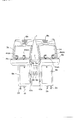
図1はこのゲーム装置の外観を示す。この図において、符号1は、ゲーム装置本体を示している。このゲーム装置本体1は箱状をしており、その下部にはキャスター2a、2b、2c、2dが設けられている。このゲーム装置本体1の二つの面には、それぞれ表示手段としてのディスプレイ3a及び3bが設けられている。これらディスプレイ3a、3bの下部の前面には、操作パネル4a及び4bが設けられている。また、ゲーム装置本体1の各操作パネル4a、4bの間の面には、硬貨投入口5a及び5bと、硬貨取り出し口6a及び6bとが設けられている。
【0042】
これら操作パネル4a、4bの間には、例えば強度的な観点から両者を連結する丸棒7が設けられている。前記各ディスプレイ3a、3bの上には、スピーカ取付孔8a及び8bが設けられており、これら孔8a、8bの内部には、スピーカ(図示せず)が設けられている。各操作パネル4a、4bの下部には開閉板9a及び9bが設けられており、内部機構を露出させることができるようになっている。
【0043】
このゲーム装置本体1の内部には、各ゲーム処理ボード10a及び10bが設けられている。なお、各ディスプレイ3a、3b、操作パネル4a、4bの操作機構、及びスピーカは図示しないがゲーム処理ボード10a、10bに接続されている。このような構造としたことにより、このゲーム装置本体1は、ディスプレイ3aまたはディスプレイ3bを単独で使用して、あるいは両ディスプレイ3a、3bを同時に使用して通信対戦形式でゲームを楽しむことができる。
【0044】
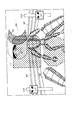
図2は、上記ゲーム装置本体で使用する操作パネルを示す斜視図である。これら操作パネル4a、4bは全く同一構成であるので、一方を説明し、他方の説明を省略する。
【0045】
この操作パネル4aは、二つのジョイステック41am及び41ahと、二つの押ボタン42am及び42ahとからなる。これらジョイステック41am、41ahは、操作パネル4a、4b上で一定の間隔で配置されている。これらのジョイステッィク及びボタンを操作することによって、遊技者は自身側のキャラクター(拳闘士)の動きを制御できる。各ジョイステック41am、41ahの前には、一定の間隔で押ボタン42am、42ahが配置されている。ジョイステック41am、41ahには、相手の闘士にパンチを繰り出せることの案内、相手の闘士からの攻撃を防御できることの案内、あるいはキャラクターを前進・後退させたりするための案内43am、43ahが表示されている。このガイダンス(案内)43am、43ahは、例えば、ストレート、アッパー、フック等のパンチの種類や、前進、後退、挑発、等の闘士の動き、その他ゲーム進行上必要な事項を含んでいる。
【0046】
図3は、同実施例のデータ処理装置が適用されたゲーム装置を示すブロック図である。このゲーム装置は、既述のディスプレイ3a、3b並びに操作パネル4a、4bの他、ゲーム処理ボード10a及び10bと、スピーカ11a及び11bとを備えている。このゲーム装置は、単独で使用するときには、ディスプレイ3a、操作パネル4a、ゲーム処理ボード10a、及びスピーカ11aからなる一つの処理系12aとして機能する。
【0047】
同様に、ディスプレイ3b、操作パネル4b、ゲーム処理ボード10b、及びスピーカ11bからなる他の一つの処理系12bも使用することができる。処理系12a、12bの双方とも、同時に、単独で使用できる。この場合には、遊戯者側の闘士の対戦相手はゲーム装置側が設定する拳闘士である。
【0048】
一方、このゲーム装置は、処理系12aと12bとを連係させることにより、通信対戦形式でゲームを楽しむことができる。この場合には、遊戯者側の闘士の対戦相手は、各操作パネル4a、4bを操作する各遊技者がそれぞれ操作する闘士である。
【0049】
これら処理系12a、12bは、全く同一構成をしているので、処理系12aのみを説明し、他の処理系12bについての説明を省略する。
【0050】
この処理系12aは、装置全体の制御を行うCPUブロック20a、ゲーム画面の表示制御を行うビデオブロック21a、効果音等を生成するサウンドブロック22a等により構成される。なお、各ブロックには符号にアルファベット「a」を付して説明するが、それらブロックを構成する各要素には符号の後にアルファベット「a」を付すことなく説明する。CPUブロック20aは、SCU(System Control Unit)200、メインCPU201、RAM202、ROM203、サブCPU204、そしてCPUバス205等により構成されている。メインCPU201は、装置全体の制御を行うものである。このメインCPU201は、内部にDSP(DigitalSignal Processor)と同様の演算機能を備え、アプリケーションソフトを高速に実行可能になっている。
【0051】
RAM202は、メインCPU201のワークエリアとして使用されるものである。また、RAM202には、この実施例では記憶エリア202C1、202C2が設けられている。これら記憶エリア202C1、202C2は例えば二つのキャラクターが対戦する拳闘ゲームの場合に、各キャラクターのもつ全余力を段階的に減少させたときの値を記憶する手段として用いるためのものである。
【0052】
ROM203には、初期化処理用のイニシャルプログラム、及びゲーム全体の内容(プログラム)等が書き込まれている。SCU200は、バス205、206、207を制御することにより、メインCPU201、VDP(VideoDisplayProcessor)220,VDP220及び230、DSP240、CPU241などの相互間のデータ入出力を円滑に行う。
【0053】
また、SCU200は、内部にDMAコントロ−ラを備え、ゲーム中のキャラクタデータ(ポリゴンデータ)をビデオブロック21a内のVRAMに転送することができる。これにより、ゲーム等のアプリケーションソフトを高速に実行することができる。サブCPU204は、SMPC(System Manager &PeripheralControl)と呼ばれるもので、メインCPU201からの要求に応じて、操作パネル4aのジョイステック41am、41ah及び押ボタン42am、42ahからの操作データを入力ポート208を介して収集し、かつパンチの種類等操作内容の判定処理を行う機能等を備えている。メインCPU201はサブCPU204から受け取った操作データに基づき、例えばゲーム画面中のキャラクタの回転変換や透視変換などの画像制御を行う。
【0054】
ビデオブロック21aは、ポリゴンデータからなるキャラクタ及び背景像に上書きするポリゴン画面の描画を行う第1のVDP(Video Display Processor)220と、スクロール背景画面の描画、プライオリティ(表示優先順位)に基づくポリゴン画像データとスクロール画像データとの画像合成、クリッピングなどを行う第2のVDP230とを備えている。
【0055】
この内、第1のVDP220はシステムレジスタ220aを内蔵するとともに、VRAM(DRAM)221及び2面のフレームバッファ222、223に接続されている。ゲームのキャラクタを表すポリゴンの描画データはメインCPU201からSCU200を介して第1のVDP220に送られ、VRAM221に書き込まれる。VRAM221に書き込まれた描画データは、例えば、16又は8ビット/pixelの形式で描画用のフレームバッファ222(又は223)に描画される。描画されたフレームバッファ222(又は223)のデータは、表示モード時に第2のVDP230送られる。このようにフレームバッファには2面のバッファ222、223が使われており、描画と表示がフレーム毎に切り替わるダブルバッファ構造を成している。さらに、描画を制御する情報は、メインCPU201からSCU200を介して第1のVDP220のシステムレジスタ220aに設定される。このシステムレジスタ220aに設定された指示にしたがって第1のVDP220が描画と表示を制御する。
【0056】
一方、第2のVDP230はレジスタ230a及びカラーRAM230bを内蔵するとともに、VRAM231に接続されている。また第2のVDP230はバス206を介して第1のVDP220及びSCU200に接続されるとともに、エンコーダ260を介してディスプレイ3aに接続されている。
【0057】
この第2のVDP230に対して、スクロール画像データはメインCPU201からSCU200を介してVRAM231及びカラーRAM230bに定義される。画像表示を制御する情報も同様にして第2のVDP230のレジスタ230aに設定される。VRAM231に定義されたデータは、第2のVDP230によりレジスタ230aに設定されている内容にしたがって読み出され、キャラクタに対する背景を表す各スクロール画面の画像データになる。各スクロール画面の画像データと第1のVDP220から送られてきたテクスチャマッピングが施されたポリゴンデータの画像データは、レジスタ230aにおける設定にしたがって表示優先順位(プライオリティ)が決められ、最終的な表示画像データに合成される。
【0058】
この表示画像データがパレット形式の場合、第2のVDP230によって、その値にしたがってカラーRAM230bに定義されているカラーデータが読み出され、表示カラーデータが生成される。また表示画像データがRGB形式の場合、表示画像データがそのまま表示カラーデータとなる。この表示カラーデータはメモリ232に蓄えられた後にD/Aコバータ260に出力される。D/Aコバータ260は、この画像データに同期信号等を付加することにより映像信号を生成し、ディスプレイ3aに出力する。これにより、ディスプレイ3aにゲーム画面が表示される。このビデオブロック21aにより映像手段が構成される。
【0059】
サウンドブロック22aは、PCM方式あるいはFM方式に従い音声合成を行うDSP240と、このDSP240の制御等を行うCPU241とを備えている。DSP240により生成された音声データは、D/Aコンバ−タ270により音声信号に変換された後にスピーカ11aに出力される。
【0060】
本実施例のゲーム装置で処理されるゲーム内容は、前述した「バ−チャファイタ−(TM)」と同様に、ステージ上で複数の闘士が格闘技(拳闘)を繰り広げる内容とする。また、対戦相手は装置側で制御する拳闘士であるとして説明する。
【0061】
続いて、メインCPU201で実施される、ポリゴンによる3次元データで表されるキャラクタ(闘士)C1,C2、ロープ等の画面(以下、ポリゴン画面という。)と、拳闘士が上るリング、拳闘士のライフカウント値、そして観客等のその他の背景等のスクロール画面との同期表示制御の処理について説明する。このうちリングは回転スクロールによって構成される。全体的な動作の説明を図4及び図5に示すメイン処理フローチャートを使用してまず説明し、例えばポリゴン構成手段、ポリゴン数増加手段、変形処理手段、及び画像処理余力表示手段等の詳細な動作については図6以降を用いて説明する。
【0062】
メインCPU201は、コインの投入がない場合には、例えばゲームの内容のダイジェスト版を表示するとともにコイン投入のガイダンス画面を表示し、これに伴う音声を出力させる(図5のステップ(S)301、ステップ302;NO)。
【0063】
コインの投入があったときには(ステップ302;YES)、メインCPU201は、例えば押ボタン42amをスタートボタンとして押下するようにガイダンス画面を表示する(S303、S304;NO)。ここで、スタートボタンが押下されたとすると(S304;YES)、自分の能力の設定をする(S305)。これは、例えば処理系12aに数人分のキャラクタの能力が設定されており、これらのキャラクタがディスプレイ3aに表示されるので、これらの中から自分の好みのキャラクタを適宜選択する。これにより、パンチ力、パンチ速度、ダメージに対する耐性、ステミナ等、そのキャラクターのもつ能力が設定されることになる。なお、キャラクターの構成は、図6を参照されたい。
【0064】
次いで、メインCPU201は対戦相手のキャラクタを設定する旨の表示をディスプレイ3aに表示するので、遊技者はこれらの中から対戦相手を適宜選択する(S306)。これにより、対戦相手のキャラクターの能力も設定される。
【0065】
ここで、メインCPU201は、ステップ307で、視点変更の表示データと、最終的にはキャラクターC1の一部(例えば、頭部、要部、上腕部等)を透視化する処理も行う。これは、まず、メインCPU201がROM203の所定の番地から表示データを読出して、これを視点変更の表示データに変換する。これにより、ディスプレイ3aには、当初、図6(a)に示すように、キャラクタ(闘士)C1、C2が相対した状態を真横から見た形態で表示される。この場合、図6では、C1、C2はキャラクター(闘士)、RPはロープ、RGはリング、LCa、LCbはライフカウンタ、BHはその他の背景である。また、この実施例では、闘士C1、C2及びロープRPをポリゴンデータで、リングRGを回転スクロールデータで、見物人等の背景BHはスクロールデータで表示されるようにしている。
【0066】
そして、対戦可能な状態になったかを判定する(S308)。この対戦状態とは、ディスプレイ3a上において自分のキャラクタ(闘士)C1が画面手前に表示されるとともに例えば頭部、腰部、上腕部等の闘士C1の一部が透明処理され、しかも、相手のキャラクタ(闘士)C2が画面の正面に向いた状態に表示されるように画像処理されることをいう。
【0067】
ここでは、いまだ対戦状態でないので(ステップ308;NO)、ROM203の番地を変更し(ステップ309)、さらに視点変更の表示処理を行う(ステップ307)。これを繰り返すことにより、図6(a)に示すように闘士C1、C2を真横から見た状態から、図6(c)に示されるように闘士C1が手前に表示されるように視点を回転させる。このように回転した表示状態の途中を表示すると、例えば図6(b)に示すように、対峙した闘士C1、C2が斜めで表示された状態になる。
【0068】
図6(a)〜(c)への移行を含む、キャラクターを画面に表示するための視点変更を伴う画像処理は、例えば図5に示すフローチャートのように動作されればよい。すなわち、メインCPU201は、まず図5のステップS401で、ROM203から読み出したデータに呼応して視点の移動座標並びにテクスチャ付きのポリゴンデータで表される闘士C1、C2、ロープRP等のポリゴンから構成される表示体の移動座標を計算する。この移動座標の計算は平行移動、回転変換、各軸に対する拡大(縮小)を1つの操作で行うことができる、従来より周知のアフィン変換を用いて行われる。
【0069】
次いで、ステップS402にて、透視変換によって、座標変換された3次元のポリゴンデータ(闘士C2、一部が透視化された闘士C1、ロープRP)が表示されるスクリーン(画面)内の位置データ(スクリーン座標)を計算し、これを第1のVDP220に送る。
【0070】
次いで、ステップS403に移行し、回転スクロール画面の回転や倒し込みに必要なパラメ−タを計算する。ここで、回転スクロール画面の「回転」とは、スクロール座標系における回転であり、3軸のいずれかを中心とする座標系全体の回転をいう。また、「倒し込み」はスクリーン画面自体の回転をいい、具体的には、遊技者から見て遠方の側のリングRG部分を縮小表示し、あるいは遊技者側のリングRG部分を拡大表示するか、又は両方の処理を同時に成すことをいう。
【0071】
次いで、メインCPU201はステップS404で前記ポリゴンデータの描画用の所定タイミングか否かを判断しつつ待機する。そして、例えば、所定のタイミングになると、ステップS405で、それまでメモリに記憶していた回転スクロール画面の回転、倒し込みの処理に必要なパラメ−タ、すなわち回転マトリクスパラメ−タ、移動量(視点の移動によるスクロール画面のX、Y移動量)、及び倍率が第2のVDP230に転送される。そして、ステップS206で、メインCPU201は表示あるいは描画の指令を実行する。
【0072】
メインCPU201は上述したステップS401〜S406の処理を定期的に繰り返す。メインCPU201で計算されたポリゴンデータは第1のVDP220に接続されたVRAM121に書き込まれ、ダブルバッファ構成に係る2枚の描画用フレームバッファ222(又は223)、表示用フレームバッファ223(又は222)によって描画及び表示が繰り返される。つまり、描画用フレームバッファ222(又は223)にテクスチャマッピングされたポリゴンデータが描画されている間に、表示用フレームバッファ223(又は222)のポリゴンデータが第2のVDP230に送られ、表示される。一方、第2のVDP230では、メインCPU201から転送されてきたパラメ−タ及びデータを使って回転スクロール画面の3軸回転及びスクリーン画面の回転(倒し込み)を計算する。
【0073】
回転スクロール画面の表示画面は、中心点を基準に視点及びスクリーン画面(TV画面)を回転変換(平行移動も含む)させ、変換後の視点から変換後のスクリーン画面を通った視線が、固定されたスクロールマップと交差する点を集めたものである。
【0074】
このように図5のフローチャートが実行されることにより、ディスプレイ3aには、図6(a)…図6(b)…図6(c)というように画面が表示されることになる。すなわち、図6(a)に示すように対峙する闘士C1、C2を真横から見た状態から、闘士C1が手前に闘士C2が後ろ側に表示されるように順次視点が移動して行くことになる。その他のシーンにおける視点移動に伴う処理も図5のフローチャートにしたがって実行される。視点の移動の途中では、図6(b)に示すように闘士C1、C2を斜めから見た状態に表示される。最終的には、ディスプレイ3aには、図6(c)に示すように、遊技者側の闘士C1が画面手前にかつ透視化状態に表示され、しかも、対戦相手側の闘士C2が画面の正面に向いた状態に表示される。
【0075】
このように自分の闘士C1が画面手前でかつ透視化状態に表示され、しかも、対戦相手側の闘士C2が画面の正面に向いた状態に表示された場合には、対戦状態になり(ステップ308;YES)、以後対戦状態のフローチャートに移行する。
【0076】
次に、対戦状態のフローチャート(ステップ310)以降に移行すると、まず、メインCPU201は、ステップ310で対戦状態のデータをROM203から読み出す。また、メインCPU201は、ステップ311でサブCPU204から操作データを取り込むとともに、ステップ312で無効操作度データの処理を行う。ここで無効操作度は、前記請求項記載の抑制手段に含まれるものである。
【0077】
このステップ312における無効操作度は、例えば拳闘の規則に沿って操作データがジョイステック41am、41ah等から入力されていないときに生じる。この無効操作度を上昇させる要因は、例えば単位時間当たり所定の回数以上ジョイステック41am、41ahを操作したり、ジョイステック41am、41ahを防御コマンド位置に一定時間入れ続ける場合である。また、無効操作度を低下させる要因は、例えばジョイステック41am、41ahから制御コマンドが入力されたり、あるいはキャラクターの移動コマンドが入力された場合である。
【0078】
また、この無効操作度を例えばRAM202等に記憶させておき、次の対戦表示データ作成画像処理を行うときに、その画像処理の程度を抑制するように反映させる。例えば、以後に説明する画像処理余力表示手段の余力量の表示に反映させたり、あるいはパンチがあたっても相手に与えるとするダメージをキャンセルあるいは低減する画像処理を実行することが考えられる。
【0079】
次いで、メインCPU201は、上述したように取り込んだ対戦データと操作データとを基に対戦表示データの作成処理を実行する(ステップ313)。
【0080】
このステップ313で形成される対戦表示データは、例えば、対戦相手の闘士C2がアッパーカットを繰り出したときに、操作パネル4aのジョイステック41am、41ah等を防御操作することにより闘士C1を防御動作させたり、あるいは、操作パネル4aのジョイステック41am、41ah等を繰り出し操作をして相手闘士C2にパンチを当てたりするための表示用データである。これにより、対戦相手の闘士C2は、パンチが当たったときに、そのパンチの種類(ストレート、ジャブ、フック、アッパーカット等)により闘士C2の顔(頭部)の変形方向を変え、パンチの強さにより闘士C2の顔(頭部)の変形量を変える。
【0081】
また、対戦相手の闘士C2から繰り出されたパンチが闘士C1に当たったときには、闘士C1の移動処理もされる。さらに、このステップ313では、闘士C1の背後側も表示させるようにし、しかも闘士C1の一部(例えば頭部、胸部、腰部、上腕部等)が透視化して表示されるようにしている。
【0082】
次いで、メインCPU201はステップ314で残存余力量表示手段に関する処理を実行する。すなわち、このステップ314では、闘士C1、C2の余力を映像にして表示できるように処理している。これは、第1に、ステップ312で得られた無効操作度を、余力(ライフカウント値)を減少させる表示として反映させる。第2に、闘士(相手側C2、自分側(遊技者側)C1)のダメージを演算し、これを余力を減少させる表示として反映させる。
【0083】
また、ダメージが所定値を超えたときには闘士をダウンさせる処理を実行させる。このように処理が行われることにより、闘士C1、C2の全余力量を表示する全余力表示手段と、闘士C1、C2の全余力量に対する残存余力量を表示する残存余力量表示手段とが実現される。また、RAM202の一部エリアに、余力量を複数記憶する記憶手段を設けており、この記憶手段内に記憶されている全余力を必要に応じて読み出すことにより全余力量を順次低減させることができる。そして、これらの画像処理を実行することにより、各闘士C1、C2が受けたダメージをライフカウンタとしてディスプレイ3a上に表示でき、かつそのダメージが各ラウンド毎に累計されるようにしている。
【0084】
このようにステップ313で得られた対戦表示データと、ステップ314で得られたライフカウンタに関するデータは表示データ作成処理(ステップ315)に渡される。ステップ315ではメインCPU201が前記ステップ313で形成した対戦表示データ、及びステップ314で形成したライフカウンタに関するデータを用いて例えば図5に示すフローチャートを実行する。これにより、ディスプレイ3a上に闘士C1、C2の対戦状態が表示される。そして、メインCPU201は、ステップ316でゲームアウトの処理を実行する。これは、闘士C1、C2のダメージを演算し、一方が3回ダウンしたときのように、ダメージが所定値を超えたときにダウン等の指令を行う。
【0085】
メインCPU201はステップ317でダウン等があったゲーム終了か否かを判断する。終了でないときは、再びステップ310に移行する。
【0086】
このようなステップ310〜ステップ317の処理を繰り返すことにより、ポリゴンによる闘士C1、C2がスクロール画面からなるリングRG上に重畳表示される。このリングRGの端部上側にはその縁に沿って細長くポリゴンデータのロープRPが上書きされている。
【0087】
そして、ゲームの進行に伴い、闘士C1、C2や視点が移動すると、闘士C1、C2の動きとスクロール画面及びその端部の上書きされたポリゴンデータからなるロープRPとが同期して表示されるため、両者がジョイステック41am、41ah等からの入力に合わせて正確に一致した動きとなって確認される。これにより、闘士C1、C2の移動、動きや視点の変化に伴う情景全体が極めて自然なものとなり、リアルな臨場感を醸し出すことができる。
【0088】
また、メインCPU201は、ステップ317で検出結果を判断し、終了のときには、ステップ318でゲーム終了の表示処理を実行する。
【0089】
次に、上記フローチャートにおける所定のステップの詳細な動作について図7以降の図面を参照して説明する。
【0090】
〔無効操作度を得る処理につて〕次に、図7〜図8を用いて無効操作度を得る処理について説明する。ここで、図7は無効操作度を得るためのフローチャートである。図8は無効操作度のグラフを示し、横軸に時間を、縦軸に無効操作度をとっている。
【0091】
この無効操作度は、例えば拳闘の規則に沿ったジョイステック41am、41ah等の操作入力がない場合に生じる度数である。この無効操作度は、単位時間当たりの連続パンチコマンドの入力回数が所定値以上であるときに得られる。また、コマンド入力のパターンが一定な場合にも、無効操作度が増加するようにしている。
【0092】
まず、拳闘の規則に沿ったジョイステック41am、41ah等の操作入力がない場合の処理について説明する。この処理は、図4のステップ312の処理に移行することにより実行される。すなわち、メインCPU201は、ステップ451において、メインCPU201は、サブCPU204から操作データが得られるか否かを判定する。ここで、操作データが得られるときには(ステップ451;YES)、メインCPU201はステップ452でこの操作データが防御コマンドか判定する。ここで、防御コマンドでないと判定されたときには(ステップ452;NO)、メインCPU201はステップ453で闘士C1の移動コマンドか判定する。このような判定する理由は、ジョイステック41am、41ahを連続的操作し、連続してパンチコマンドが入力されているか否かを判定するためである。
【0093】
闘士C1の移動コマンドでないとき(ステップ453;NO)、拳闘の規則に従った有効なパンチではなく、ただパンチを振り回しているだけとし、メインCPU201はステップ454でレジスタK3に操作データの回数を次々と加算させる。このレジスタK3は、例えばRAM202の一定のエリアに設ければよい。また、レジスタK3は、操作パネル4a、4bが連続して操作されたたことによるパンチコマンドが累計されてゆくことになる。
【0094】
次いで、メインCPU201は、一定時間x〔秒〕経過したかを判定する(ステップ455)。この判断は、単位時間x〔秒〕当たりに、何発のパンチコマンドが入力されたかを判定するためのものである。そして、一定時間x〔秒〕経過しないときには(ステップ455;NO)、この処理ルーチンを抜ける。
【0095】
一方、一定時間x〔秒〕経過したときには(ステップ455;YES)、メインCPU201はステップ456でレジスタK3のデータを読み込む。この読み込んだデータは、単位時間(x〔秒〕)当たりのパンチの数yとなる。
【0096】
また、メインCPU201は、レジスタK3のデータが1y発以上であれば(ステップ457;NO)、すなわち、拳闘の規則に沿った操作が与えられていないと判断し、RAM202の所定のエリアに設けた無効操作度記憶エリアに、無効操作度が一つ加算されたように記憶させる(ステップ312 )。この記憶エリアに記憶された無効操作度の値は、図8に示すように、時刻x1で無効操作度が1つ上がった状態となっている。そして、メインCPU201は次の処理に備え前の内容の影響を与えないようにするためにステップ459でレジスタK1〜K3をリセットし、この処理を抜ける。
【0097】
また、同様に、ステップ451〜455の処理を実行し、時刻x2においてステップ456〜457の処理を実行して2y発が得られたときには、無効操作度記憶エリアに、前の値にさらに2個累計されたように記憶させる(ステップ458)。この記憶エリアの値は、図8に示すように、時刻x2で無効操作度かさらに2つ加算された値となっている。そして、メインCPU201は次の処理のためにステップ459でレジスタK3をリセットし、この処理を抜ける。
【0098】
さらに、同様に、ステップ451〜455の処理を実行し、時刻x3においてステップ456〜457の処理を実行して1y発が得られたときには、無効操作度記憶エリアに、前の値にさらに2個累計されたように記憶させる(ステップ458)。この記憶エリアの値は、図8に示すように、時刻x3で無効操作度がさらに1つ加算された状態となる。そして、メインCPU201は次の処理のためにステップ459でレジスタK3をリセットし、この処理を抜ける。
【0099】
同様に、ステップ451〜455の処理を実行し、時刻x4においてステップ456〜457の処理を実行して1y発が得られたときには、無効操作度記憶エリアに、前の値にさらに2個累計されたように記憶させる(ステップ458)。この記憶エリアの値は、図8に示すように、時刻x4で無効操作度がさらに1つ加算された状態となる。そして、メインCPU201は次の処理のためにステップ459でレジスタK3をリセットし、この処理を抜ける。
【0100】
このように拳闘の規則に沿ったジョイステック41am、41ahの操作がないときには、無効操作度がますます高い値となる。
【0101】
次に、無効操作度が低下する場合について説明する。コマンドが入力されると(ステップ451;YES)、メインCPU201はステップ452で防御コマンドか判定する。防御コマンドのときには(ステップ452;YES)、メインCPU201は、ステップ460で防御コマンドが短時間で他のコマンド等(あるいは中立位置)に変更されたか判定する。これは、拳闘の規則に沿った操作であるかを判定するためである。
【0102】
防御コマンドが短時間で他のコマンド等に変更されたときには(ステップ460;YES)、メインCPU201はステップ461で無効操作度記憶エリアの無効操作度から1つ引いた値とする。この記憶エリアの値は、図8に示すように、時刻x5で無効操作度が1つ下がった状態となる。なお、この処理を通過した後には、メインCPU201は次の処理のためにステップ462でレジスタK1〜K3をリセットする。
【0103】
次に、ノーコマンドの場合の動作説明をする。コマンド入力がないとき(ステップ451;NO)、メインCPU201はステップ471で例えばレジスタK1=K1+1の処理をする。これは、一定時間の間に、ノーコマンドであることを検出するために行う加算である。また、このレジスタK1は、例えばRAM202の所定のエリアに設けたものを使用すればよい。
【0104】
次いで、一定時間α(秒)経過したか判定する(ステップ472)。この時間の判定は、一定期間継続してノーコマンドであることを検出するための判断である。一定時間α(秒)経過しない場合(ステップ472;NO)、この処理を抜ける。
【0105】
一方、一定時間α(秒)経過した場合(ステップ472;YES)、メインCPU201はステップ473でレジスタK1の値を読み込む。このレジスタK1の値は一定時間ノーコマンドである場合の値であり、この値が所定値より大きければ(ステップ474;YES)、一定時間ノーコマンドであるので、メインCPU201はステップ475で無効操作度記憶エリアから無効操作度を1つ減算する。これにより、この記憶エリアの値は、図8に示すように時刻x7で無効操作度が1つ低下した状態になる。そして、ステップ476で次の処理のために各レジスタK1〜K3をリセットする。なお、レジスタK1の値が一定の値未満のときには(ステップ474;NO)、ステップ476で各レジスタK1〜K3をリセットし、この処理を抜ける。
【0106】
さらに、防御コマンドを入れ続けた場合の動作について説明する。この場合、メインCPU201は、ステップ451、452、460を通過し、ステップ481で例えばレジスタK2=K2+1とする。このレジスタK2は、例えばRAM202の所定の記憶エリアを使用すればよい。また、このレジスタK2は、防御コマンドの入力が継続していることを測定するためのものである。
【0107】
次いで、メインCPU201はステップ482で一定時間経過したか判断する。この時間判定は、一定時間の間、防御コマンドが入りっぱなしになることを判定するためのものである。一定時間経過していないときには(ステップ482;NO)、この処理を抜ける。
【0108】
一方、一定時間経過したときには(ステップ482;YES)、メインCPU201はステップ483でレジスタK2の値を読み取る。ここで、メインCPU201は、レジスタK2の値が所定の値より大きいときには(ステップ484;YES)、防御コマンドが入れっぱなしの状態であるから、ステップ485で無効操作度記憶エリアの、無効操作度を一つ加算する。この記憶エリアの値は、図8に示すように、時刻x9で無効操作度が1つ上がた状態になる。この処理が終了した後に、後の処理のためにステップ486でレジスタK1〜K3をリセットする。このように防御コマンドを入れっぱなしにすると、無効操作度が上昇する原因となる。
【0109】
なお、その他無効操作度が低下する場合の動作について説明する。これは、闘士C1の移動コマンドが入力されたときに動作するものである。すなわち、闘士C1の移動コマンドが入力されたときに(ステップ453;YES)、メインCPU201はステップ441で無効操作度記憶エリアの無効操作度を1つ減算する。この後に、後の処理のために、ステップ442でレジスタK1〜K3をリセットする。
【0110】
上述したように上記各ステップ451〜492では、拳闘の規則に沿った操作がジョイステック41am、41ah等から入力されているか否かを判定する。この無効操作度記憶エリアに記憶された無効操作度を、後の処理において画像処理の程度を抑制するために使用する。例えば、ライフカウンタの値を減少させる処理に反映し、あるいはパンチ等が相手の闘士C2に当たっても、これの有効性を小さくする、あるいはこの有効性を否定するようにする。
【0111】
このようにすることにより、ジョイステック41am、41ah等の確実な操作を遊技者に促すとともに、例えば拳闘の場合の実際の動きを遊戯者に提供して、かつそのようにジョイステック41am、41ah等が遊技者に操作できるようにする。
【0112】
〔ポリゴン構成手段、ポリゴン数増加手段の動作〕次に、通常の表示状態では、闘士C2の顔(頭部)を最小限の数のポリゴンから構成し、この顔(頭部)を変形して表示させる際に、この顔(頭部)を構成するためのポリゴン数を増加させた後、この増加されたポリゴン数に基づいて顔(頭部)の変形させる画像処理について、図9〜図11を参照して説明する。
【0113】
まず、メインCPU201は、ステップ500でフラッグFLGが0か否かを判定する。この判定は、変形処理のためのテーブルデータの読出し処理を行うかか否かを判定するためのものである。読出しを行っている場合は特定の処理フローチャートに、読出しを行っていないときには通常の判断処理を行う。
【0114】
ここで、フラッグFLGは当初は0に設定されているので、メインCPU201はステップ501で闘士C2の顔(頭部)を最小限の数のポリゴンから構成する画像処理を行う。この画像処理は、例えば、闘士C2の顔(頭部)の各面を一つの正方形のポリゴンから構成する。これにより、例えば図10(a)に示すように、闘士C2の顔(頭部)C2fが6つのポリゴンからなる立方体(6面体)に形成される。つまり、一つのポリゴンを3次元座標における4頂点を指定することにより配置し、各面は4頂点のうち2頂点を共有させることにより、闘士C2の顔(頭部)C2fを六面体となるポリゴンの集合から表現している。
【0115】
実際の闘士の各種表情を構成する、正面部、背面部、左右の側面部、平面部、そして底面部の各模様(テクスチャー)を、予めビデオカメラ等によって撮影するかあるいは別に構成し、これらをROM203に記憶させておく。
【0116】
そこで、ステップ502では、この表情のテクスチャーや、各右側面、左側面、背面、頭頂部等のテクスチャーを、該当するアドレスのポリゴンにマッピングする。また、このステップでは、全てのポリゴンについて、この場合は6面について、テクスチャーのマッピングが終了したかの判断も行う。これにより、図10(b)に示すように、表情が現れた闘士C2の頭部が形成される。なお、ここでは図面の表現を簡単にするために、頭部の正面のポリゴンにのみテクスチャー(顔の模様)を貼り付けた場合を示しており、その他の面へのテクスチャーの図示を省略する。
【0117】
次に、メインCPU201は、サブCPU204から操作データを取り込み、操作データの有無を判定する(ステップ503)。操作データがあるときには(ステップ503;YES)、メインCPU201はステップ504で操作データの方向、強さ、速さ等からパンチコマンドの内容等(防御コマンドもある)を特定する。そして、その処理(ステップ504)の結果から攻撃であると判定されると(ステップ505;YES)、メインCPU201はステップ506で闘士C1のパンチの座標を読む。つづいて、メインCPU201はステップ507で対戦相手の闘士C2の頭部の座標を読む。これら座標が一致したか否かを判定する(ステップ508)。この判定は、闘士C1、C2の衝突判定を行っていることに相当する。
【0118】
これら座標が一致した時点で(ステップ508;YES)、闘士C1、C2の衝突判定が肯定されたことになり、闘士C1(遊戯者側のキャラクター)のパンチが闘士C2(対戦相手側のキャラクター)の顔面にあたったことになる。そこで、変形処理に移行するためにフラッグFLGに“1”を設定する(ステップ509)。
【0119】
メインCPU201はステップ509で第1のパンチと第2のパンチとの判定をする。この実施例では、説明を簡略化するため、2種類のパンチのみとして説明する。また、この実施例では、無効操作度の反映をパンチの効力を減少させるようにして処理するものとして説明する。もちろん、このようにパンチの効力が減少させるようにせず、ライフカウンタの値が低下するようにしてもよい。
【0120】
まず、第1のパンチの場合には(ステップ510;1P)、ステップ511において無効操作度記憶エリアの値が一定値以下なら、ジョイステック41am、41ah等の操作が拳闘の規則にない動きをしていることが少ないと判定し、ステップ512以降の処理に移行する。
【0121】
このステップ512では、最小限の数のポリゴンから構成された闘士C2の顔(頭部)C2fについて、この部分の各面を構成するポリゴン数を増加させる。これにより、図11(a)に示すように、それぞれ矩形(四角形)が割り当てられた6つのポリゴンから構成された顔(頭部)C2fの各面において、一つのポリゴンから8(列)×8(行)に配列された複数のポリゴンに変更される。
【0122】
また、各面の複数のポリゴンの一つ一つのアドレスは指定されており、これらアドレスとポリゴンの変形用データとがパンチ(パンチの方向、パンチの種類、パンチの強弱)毎にテーブル化されていて、これらテーブルの多数がROM203に格納されているものとする。また、このステップ512以降に入ると、どのテーブルから変形データを取り込むかがパンチの種類、パンチの方向、強さ、闘士Cの種類等により指定されている。
【0123】
次に、メインCPU201は、顔(頭部)C2fの部分が多数のポリゴンで構成されていて、各ポリゴンの各アドレスについて変形用のテーブルからポリゴンの変形データを取り出し、このアドレスに相当する部分の顔の表情のテクスチャーを変形し、当該アドレスに該当するポリゴンにマッピングする(ステップ513)。ポリゴンの変形は、矩形のポリゴンの4頂点を設定することにより可能になる。この場合は、6面体の各面に、単に4頂点のあるポリゴンの多数が配置されたような変形データが得られることになる。
【0124】
そして、上記変形データを基に顔(頭部)C2fの全てのポリゴンについてマッピングが終了したか判定する(ステップ514)。全てのポリゴンにテクスチャーのマッピングが終了しないときには(ステップ514;NO)、マッピング処理を続行する(ステップ513、514)。また、全てのポリゴンにテクスチャーのマッピングが終了したときには(ステップ514;YES)、図11(b)に示すように6面体の部分に通常の顔が表示される。ついで、メインCPU201は、ステップ515で闘士C2用のライフカウンタのデータを所定の値だけで減少させた後、ステップ516でROM203の読出し番地やテーブル読出し番地を更新して、この処理を抜ける。
【0125】
再び、このルーチンに入ると、フラッグFLGが“1”となっているので、メインCPU201は、ステップ520にて所定の変形用テーブルの所定の番地から変形データを読み出してくる。この変形データは、図12(a)に示すように、最小単位の各ポリゴンの各番地P11,P12,P21,P22,…,P81,P82,P91,P92,…,P18,P19,P28,P29,…,P88,P89,P98,P99として得られることになる。
【0126】
そこで、メインCPU201は、ステップ521で、このパンチに伴う表情のテクスチャーを選び、かつこれを変形し、各テクスチャーを該当する各番地P11,P12,P21,P22,…,P81,P82,P91,P92,…,P18,P19,P28,P29,…,P88,P89,P98,P99にマッピングする。これにより、図11(b)に示すように、多数のポリゴンによって構成される6面体が歪んだ変形を呈することになる。
【0127】
これらの各番地に全てテクスチャーがマッピングが完了したか判定する(ステップ522)。全てのテクスチャーのマッピングが完了したときには(ステップ522;YES)、当該変形テーブルの全データを読み出したか判定する(ステップ522)。読み出していない場合には(ステップ523;NO)、ROM203と変形テーブルの読出し番地の更新をする(ステップ516)。
【0128】
このルーチンを通る度に、変形テーブルのデータが番地更新した状態で読み出され(ステップ500、S520、S521、S522)、次々と変形データが得られることになり、歪んだ顔(頭部)C2fが表示できることになる。これにより、図12(b)に示すように歪んだ形状となった頭部と、表情が表示されるようになる。
【0129】
なお、変形テーブルの変形データを全て読み終わったときには(ステップ523;YES)、顔(頭部)C2fの変形が終了し、元の状態に戻ったときであるので、フラッグFLGに“0”を設定してステップ516に進む。
【0130】
一方、パンチが第1のパンチであって(ステップ510;1P)、かつ無効操作度が大きい場合には(ステップ511;YES)、変形量が少ない第2の変形テーブルのデータを読み出す処理に移行する(ステップ525)。
【0131】
ステップ525で最小限の数のポリゴンから構成された闘士C2の顔(頭部)C2fを、多数のポリゴンで構成されるように増加させる。これにより、図11(a)に示すように、6面体で構成されたポリゴンの各面は、多数のポリゴンに変更される。次に、ステップ526で、表情のテクスチャーを各ポリゴンの変形データをマッピングする。そして、全ポリゴンについてマッピングが終了したかを判定する(ステップ527)。これにより、図11(b)に示すように6面体の部分に通常の顔で表示される。
【0132】
そして、メインCPU201は闘士C2用のライフカウンタのデータを通常値で減少させて、ステップ516でROM203の読出し番地及び第2の変形テーブルの読出し番地を更新し、この処理を抜ける。
【0133】
このように第1のパンチであって、本来なら闘士C2に大きなダメージを与えられる場合でも、無効操作度が大きいと、通常のパンチの扱いとなってしまう。
【0134】
また、パンチが第2のパンチであって(ステップ510;2P)、かつ無効操作度が小さい場合には(ステップ529;YES)、ステップ525〜ステップ528、ステップ500、ステップ520〜ステップ534の処理を実行する。これにより、図11(a)に示すように、6面体で構成されたポリゴンの各面は、多数のポリゴンに変更された後、図11(b)に示すように6面体の部分に通常の顔が表示される。多数のポリゴンによって構成される6面体の顔(頭部)C2fが歪み、歪みに伴った表情が表示されるようになる。なお、この場合、第2の変形テーブルであったので、変形の程度が図12より少ない。
【0135】
なお、上記処理では、闘士C2の処理についてのみ説明していたが、ディスプレイ3a上には、図13に示すように、闘士C1の頭部、胸部が透視化処理され、かつ闘士C1の腕等は通常のポリゴン処理で表示される。もちろん、腕等が闘士C2にかかる場合には、この腕についても透視化処理を施しても良い。この透視化処理の一つとしてメッシュ化処理がある。このメッシュ化処理は、図18に示すように、例えば4頂点のポリゴン90が、XY軸について例えば9ドットで構成されているとし、X軸の座標値+Y軸の座標値=Sの値が偶数のピクセルのみ描画され、Sの値が奇数のときには描画をスキップし、書き込みをしないようにしている。このようにすることにより、メッシュ化したポリゴンが得られる。
【0136】
また、各闘士C1、C2等の表示については、ポリゴンの優先順位の判定でディスプレイ3aの一番手前に表示されることになる。また、闘士C2はポリゴンの優先度が2番目であるので、闘士C1の後ろであって、かつロープRPの手前に表示される。また、闘士C1の頭部や胸部がメッシュ処理されているので、闘士C1が画面手前に表示されていても、闘士C2は形状、表情とも見えることになる。また、ロープRPはポリゴンの優先度が3番目であるので、一番後ろ側に表示されることになる。さらに、リングRGは、回転スクロールで表示されている。また、ライフカウンタLCa、LCbはスクロールで表示されているので、何時もディスプレイ3aの画面の左右に表示されている。図示しないが、見物客等を背景BHとして表示させている。
【0137】
次に、パンチが第2のパンチで(ステップ509;2P)、かつ無効操作度が大きい場合には(ステップ529;NO)、ROM203の読出し番地を更新し(ステップ516)、この処理を抜ける。つまり、無効操作度が大きいときには、拳闘の規則に従った操作が入力されていないものとし、有効なパンチを繰り出し当たっても、これを無効あるいはその威力を低減するようにしている。
【0138】
一方、ステップ508で不一致になったとき(ステップ508;NO)、メインCPU201は、ステップ531で対戦相手の闘士C2の他の座標を読み出す。
【0139】
そして、メインCPU201は、ステップ532でこの闘士C2の座標と闘士C1のパンチの座標とを比較する。一致していれば、対戦相手の闘士C2の体に当たったので(ステップ532;YES)、この場合は変形等はせず、単にダメージを相手に与えたものと扱う。そして、メインCPU201はステップ533で闘士C2用のライフカウンタのデータを通常値で減少させて、ROM203の読出し番地を更新し(ステップ516)、この処理を抜ける。
【0140】
また、防御の場合には(ステップ505;防御)、メインCPU201はステップ541で対戦相手の闘士C2のパンチの座標をよむ。また、メインCPU201は、ステップ542で闘士C1の手の座標を読む。そして、一致したときには(ステップ543;YES)、防御が成功したものとして処理が実行される(ステップ544)。
【0141】
一方、防御で両座標が不一致のとき(ステップ543;NO)、メインCPU201は、ステップ545で闘士C1の他の部分の座標を読む。対戦相手の闘士C2のパンチの座標と、闘士C1の他の部分の座標とが一致したときには、対戦相手の闘士C2のパンチが当たったので、ステップ547で、対戦相手のパンチ力に応じて例えば闘士C1を例えばダウン状態に移動させたりする。
【0142】
そして、メインCPU201は、ステップ548で闘士C1のライフカウンタの値を対戦相手のパンチの有効性に応じて減少させる。そして、ROM203の読出し番地を更新し(ステップ518)、この処理を抜ける。
【0143】
なお、操作データがない場合でも(ステップ503;NO)、対戦相手の闘士C2がパンチを繰り出してくれば(ステップ550;YES)、ステップ541〜ステップ548の処理に移行して処理される。
【0144】
また、操作データがなく(ステップ503;NO)、対戦相手の闘士C2がパンチの繰り出しがないときには(ステップ550;YES)、何の処理も行わず、ROM203の読出し番地を更新し(ステップ518)、この処理を抜ける。
【0145】
上述したような各処理ステップを処理することにより、通常は、少ないポリゴンで表示を行うことにより処理負荷を軽くし、闘士C1のパンチが闘士C2の顔面等に当たって表情を変化させたいときには6面体からなるポリゴンを多数のポリゴンで構成し、これらを変形させている。これにより、面白いゲーム環境を提供することができる。また、通常の表示の場合、顔(頭部)C2fを6面体で構成したので、パンチの当たっていないときには、最小限のポリゴンで済む。
【0146】
なお、上記実施例では、各ポリゴンのアドレスが指定されており、これらアドレスとポリゴンの変形データがテーブル化したものから、パンチの種類に対する変形データを得ることにより、闘士C2の頭部等の変形データを得ていたが、もちろん計算によって変形データを求めるようにしてもよい。
【0147】
〔画像処理余力表示手段の動作〕次に、闘士C1、C2のライフカウンタLCa、LCb(図13参照)の表示処理や、この表示に必要なデータ処理について、図14〜図17を参照して説明する。図14は画像処理余力表示処理についてのフローチャートである。また、図15〜図17はライフカウンタLCa、LCbの表示状態の例を示す説明図である。また、図15〜図17において、ライフカウンタLCaのみ表示されているが、もちろん、ライフカウンタLCbも同様に表示される。説明を簡単にするため、図15〜図17ではライフカウンタLCaのみを表示して説明する。なお、図15〜図17において、ライフカウンタLCaは、全余力量を示すメータMと、全余力量に対する残存余力量を表示する手段としての顔Fと、ラウンドを表す数字(「1」、「2」、「3」)と、これら数字の上で点滅あるいは点灯させる表示体とから構成されている。
【0148】
最初に、ゲームが開始されたときには、闘士C1用の全余力量が記憶エリア202C1に記憶されているので、ステップ601で、この記憶エリア202C1からのデータを読み出す。
【0149】
次に、上記ステップ313の処理により闘士C1がパンチを食らって(画像処理の進行に伴って)ライフカウンタに関するデータが低下すると、この値に基づいてステップ602で残存余力量を減少させる。
【0150】
ステップ603では、前のステップのメータMのデータと、残存余力量のデータとから表示データを作成する。これにより、メータMを表示するデータが形成され、かつ全余力量に対する残存余力量のデータが形成される。最初は、メータMのデータと残存余力量のデータは同一だから、ライフカウンタLCaは、メータMと顔Fとが同一位置で表示される(図15のゲームスタート(時刻t1))。
【0151】
そして、ステップ604において、メータM(全余力量)に対して顔F(現存余力)の関係を判定する(ステップ604)。
【0152】
メータM(全余力量)の底に顔F(現存余力量)が達しない場合には(ステップ604;NO)、この処理を抜ける。したがって、単に残存余力量が減少してゆくように表示される。すなわち、ステップ601〜604の処理を繰り返すと、顔Fのみが単に低下してゆく表示とする(図15時刻t1、t2)。
【0153】
メータM(全余力量)の底に顔F(現存余力量)が達したときには(ステップ604;YES)、ステップ605で3回目のダウンか判断する。3回目のダウンでない場合には(ステップ605;NO)、ライフカウンタLCaの数字「1」の部分を点滅させる(ステップ606)。これにより、闘士C1は1stダウンしたことになる。また、ライフカウンタLCaは、図15(t3)に示すように、1stダウンしたことになり、数字「1」の上が点滅状態に表示され、かつ顔Fが一番下に位置して表示される。
【0154】
レフリーカウントが入る前に、ステップ607において、記憶エリア202C1の値を一定量減少させる。また、このステップで、記憶エリア202C1の値を読出し、ノックアウト回避点(KO)のデータを作成あるいは該当するデータをメモリから読み出し、顔Fの位置をメータMから話した状態の表示されるようなデータを形成する。このデータが表示されることにより、図15(t4)に示すように、顔FがメータMから離れた位置で表示される。また、同図に示すように、メータMには、Aポイントが表示され、矢印Yに示すようにBポイントの表示がされる。このBポイントは時刻t1のときより短くなっている(メータMが短く表示される)。そして、Cポイントがソフト的に設定あるいは決定され、ノックアウト回避点(KO)が表示される。
【0155】
また、闘士C1の体力は、ステップ608において所定の回復条件により回復される。カウント終了条件は、カウント「10」以内に顔FがAポイントに到達した場合である。また、Cポイントはモーション強制発生点である。そこで、体力回復に従って、残存余力量を回復させる(ステップ608)。また、顔Fを上昇させる表示をする(ステップ608)。これにより、図15(t5)に示すように、ライフカウンタLCaの顔Fが矢印Yのように上昇する。そして、9カウントでBポイントあるいは、A〜Bポイントのエリアに入ると(ステップ609)、再び、次のラウンド目の処理に入る指令を入力する(ステップ610)。なお、9カウントでBポイントあるいは、A〜Bポイントのエリアに入らないと(ステップ609;NO)、例えばゲームオバーの処理にする(ステップ611)。
【0156】
2ラウンド目に入ると、ステップ601でメータMのデータが読み出される。また、ステップ602で残存余力量を減少させる。これらのデータをステップ603で表示処理すると、ディスプレイ3aには、図16(t6)に示すように、顔Fが矢印Yの方向に低下する状態で表示される。
【0157】
そして、ステップ604、605を通過し、かつ残存余力量が全くなくなると、ライフカウンタLCaは、図16(t7)に示すように、2回目のダウンしたことになり、数字「2」の上が点滅状態に表示され、かつ顔Fが一番下に位置して表示される(ステップ606)。
【0158】
レフリーカウントが入る前に、ステップ607において、ライフカウンタLCaの全体量を減少させ、ノックアウト回避点(KO)が出力させ、かつ顔Fの位置を変更する。これにより、図16(t8)に示すように、顔Fが離れた位置で表示される。
【0159】
また、闘士C1の体力が回復されたときに、顔Fを上昇させる表示をする(ステップ608)。これにより、図16(t9)に示すように、ライフカウンタLCaの顔Fが矢印Yのように上昇させる。そして、回復すると(ステップ609)、再び、次のラウンド目に入る指令をする(ステップ610)。
【0160】
3ラウンド目に入ると、再び、ステップ601〜604の処理を行う。これにより、ディスプレイ3aには、図17(t10)に示すように、顔Fが矢印Yの方向低下する状態で表示される。
【0161】
そして、残存量がなくなると(ステップ604)、ライフカウンタLCaは、図17(t11)に示すように、3回ダウンしたことになり、数字「3」の上が点滅状態に表示され、かつ顔Fが一番下に位置して表示されて、ステップ612でゲームオバー表示をする。なお、残存余力があるときには、何も処理をせずに、この処理を抜けてゆく。
【0162】
このように処理ステップが実行されると画像処理余力表示手段の処理が行われることになる。この処理は、全余力表示手段による全余力量の表示処理と、残存余力量表示手段による全余力量に対する残存余力量の表示処理と、全余力変化手段による画像処理の進行に伴って全余力を順次減少させる処理とである。
【0163】
ライフカウンタLCaの表示処理については、上述したものであるから、各闘士C1、C2のダメージ等について現実味の有るゲーム展開を味わうことができる。
【0164】
なお、この実施例では本発明のデ−タ処理装置を適用する機器としてゲーム装置を挙げたが、本発明のデ−タ処理装置は必ずしもそれに限定されるものではなく、データ処理装置単独で実施してもよいし、またシミュレーションシステムなどに一体的に搭載することもでき、より少ない演算量で臨場感溢れる画像を提供することができる。
【0165】
【発明の効果】
以上説明したように本発明によれば、画像処理手段により表示体を変形して表示させる際に、表示体を構成するポリゴン数を増加させているために、請求項2記載の発明のように、表示体の少なくとも一部を最小限の数のポリゴンから構成し、表示体の部分を変形して表示する必要が無い場合は、そのポリゴン数を維持し、これを変形する必要がある場合は、この部分のポリゴン数を増加させるので、この部分を変形する必要が無い場合、余分のポリゴン数を他の表示体表示に適用することができる。したがって、制限されたポリゴン数の有効利用が図られる。
【0166】
さらに、ポリゴン数を増加させることによってこのような変形の表示が可能になりあるいはより詳細の変形画像を構成することができる。また、表示体の変形が不用なときには、画像処理負荷を小さくでき、かつ、必要に応じて多くのポリゴン数で表示体を構成でき表示の態様を多様化できる。
【0167】
本によれば、表示体の一部を、各面がそれぞれ一つのポリゴンから構成される多面体に形成し、表示体の一部を変形して表示するときには、多面体の各面を複数のポリゴンに増加させているので、簡単な多面体を構成するようにしてポリゴン数を極力低減でき、多面体を変形して表示することが必要なときに、各面のポリゴン数を増加させて表示の多様化を図っている。
【0168】
本発明によれば、表示体をそれぞれ身体を模擬した第1と第2のキャラクターとを含んで構成し、この第1のキャラクターの頭部と第2のキャラクターとの衝突を判定して、この頭部の変形が必要な場合を確実に把握し、第1のキャラクターの頭部を各面が一つのポリゴンから構成される6面体として構成し、さらに、衝突判定が肯定された時に、この6面体の各面のポリゴン数を増加させて頭部の変形表示を可能しているので、表示の多様化を図ることができる。
【0169】
本によれば、キャラクターの頭部の各面を一つのポリゴンから構成可能な矩形状に形成することにより、頭部の変形を要しない場合、頭部の各面のポリゴン数を最も最小にすることができる。
【0170】
本によれば、画像処理の進行に伴って全余力を順次変化させて、画像処理の結果が画像処理の余力に反映させ、この全余力が順次減少されることにより、例えば格闘ゲームにおける画像処理に際し、表示体に実際には蓄積されるダメージを正確に再現することができ、現実感溢れる画像処理を提供することができる。
【0171】
本発明によれば、記憶手段に全余力量を段階的に減少させた値を記憶し、画像処理状況に応じてこの記憶手段から該当する値の全余力量を順次読み出しているので、画像処理の状況に応じて全余力量を確実に変化させることができ、例えば現実感に溢れるゲーム環境を提供できる。
【0172】
本発明によれば、画像処理の全余力は、表示体としてのキャラクターに対してライフカウント値として提供され、視聴者は自己が制御できるキャラクターの残存寿命を事前に知ることができるため、例えば現実感に溢れるゲーム環境を楽しむことができる。
【0173】
本発明によれば、表示体はポリゴンから構成され、所定の視点から見た表示体の画像を形成する際、視点の手前側にある表示体のポリゴンの一部についてこれを透視化する処理が実行されているので、手前の表示体が透けて操作者に見えることから、3次元座標系に表示体を構成しても、相手側の表示体と操作者や遊技者側の表示体とを同時に確認しながら、確実な操作と現実味溢れる画像処理環境を実現することができる。
【0174】
本発明によれば、メッシュ化処理によってこの透視化が確実に実現される。
【0175】
本発明によれば、格闘技ゲームの場合のルールのように、予定されている規則に沿った操作が操作手段に入力されているか否かが判定され、表示体に与えられる画像処理の程度を抑制されるようにしたので、あらかじめ決められた規則にない操作手段の操作を防止し、現実感溢れるゲーム環境のような画像処理環境を提供することができる。
【図面の簡単な説明】
【図1】本発明に係るデータ処理装置を適用したゲーム装置の一実施例の全体斜視図である。
【図2】同実施例の操作パネル部分の詳細を示す斜視図である。
【図3】同実施例の処理系を示すブロック図である。
【図4】同実施例の全体的な処理ステップを示すフローチャートである。
【図5】同実施例の表示処理の具体的動作を示すフローチャートである。
【図6】同実施例で対戦する二つの闘士が対面している状態から回転して対戦状態に表示される動作を説明するための図である。
【図7】同実施例の無効操作度処理手段の動作を説明するためのフローチャートである。
【図8】同実施例の無効操作度の状態を示すグラフである。
【図9】同実施例のポリゴン構成手段、ポリゴン数増加手段の動作を説明するためのフローチャートである。
【図10】同実施例のポリゴン構成手段の動作の説明図である。
【図11】同実施例のポリゴン数増加手段の動作の説明図である。
【図12】同実施例のポリゴン数増加手段の動作の説明図である。
【図13】同実施例のポリゴン構成手段、ポリゴン数増加手段の動作により表示される画面を示す図である。
【図14】同実施例の画像処理余力表示手段の動作を説明するためのフローチャートである。
【図15】同実施例の画像処理余力表示手段により得られるライフカウンタの表示例を示す説明図である。
【図16】同実施例の画像処理余力表示手段により得られるライフカウンタの表示例を示す説明図である。
【図17】同実施例の画像処理余力表示手段により得られるライフカウンタの表示例を示す説明図である。
【図18】同実施例のメッシュ処理の動作を説明するための説明図である。
【符号の説明】
1 ゲーム装置本体(データ処理装置)
3a、3b ディスプレイ
4a、4b 操作パネル
5a、5b 硬貨投入口
6a、6b 硬貨取り出し口
8a、8b スピーカ取付孔
10a、10b ゲーム処理ボード
11a、11b スピーカ
12a、12b 処理系
20a CPUブロック
21a ビデオブロック
200 SCU
201 メインCPU
204 サブCPU
220 第1のVDP
220a システムレジスタ
221 VRAM
222,223 フレームバッファ
230 第2のVDP
230a レジスタ
230b カラーRAM
231 VRAM
232 フレームメモリ
260 エンコーダ[0001]
[Industrial application fields]
The present invention relates to an image processing apparatus and a game apparatus including the image processing apparatus, and more particularly, to an image processing apparatus that performs image processing for a game such as a martial arts game and a game apparatus for executing the game It is about.
[0002]
[Prior art]
With the development of computer graphics technology in recent years, image processing devices such as game devices and simulation devices have become widely popular. For example, a game device includes a peripheral (peripheral device) such as a joystick (an operation stick), a button, a monitor, and the like, and a game device main body that executes data communication, image processing, acoustic processing, and the like with the peripheral. Yes. Image processing in this game apparatus occupies a very large weight in increasing the commercial value, and in recent years, the technology for reproducing moving images has also been refined.
[0003]
As an example of the game apparatus, “Title Fight (trademark)” manufactured by SEGA ENTERPRISES is known. In this case, a character (combatant) is composed of sprites (one picture), and a background is composed of a scroll screen.
[0004]
However, this makes it impossible to change the viewpoint and represent the character in three dimensions. Therefore, in recent years, a three-dimensional shape is composed of a plurality of polygons, and textures (patterns) are mapped to the polygons so that characters can be displayed even when viewed from a predetermined viewpoint. .
[0005]
As an example of this, while drawing with polygon data with texture mapping on a three-dimensional character, drawing a special background part that requires movement according to the character's movement or changing the viewpoint with polygon data with texture However, a TV game apparatus that draws a background other than that on a scroll screen is known (for example, a martial art game of “Burcha Fighter (TM)” manufactured by SEGA ENTERPRISE). In this case, coordinate conversion and perspective conversion of textured polygon data that forms a special part of the character and its background are performed according to changes in the character's movement and viewpoint, and rendering is performed for each frame. .
[0006]
As a result, compared to the case where the character is composed of a sprite or a scroll screen, the character (for example, the above-mentioned warrior) and a special partial screen (for example, the above-mentioned warrior ring) for the background closely related to the movement of the character Can be expressed three-dimensionally from the viewpoint of
[0007]
[Problems to be solved by the invention]
In the above-described image processing apparatus such as the conventional TV game apparatus, the amount of data processing for coordinate conversion and texture mapping for each frame accompanying the movement of the character and the change of the viewpoint becomes enormous, and the data processing apparatus such as the TV game apparatus main body. The computation load on the CPU of the main body was significantly increased. In order to cope with this increase in calculation load, a CPU with high calculation capability is required, which has been a cause of an increase in manufacturing cost.
[0008]
On the other hand, when trying to process image data at a certain high speed using a CPU with a processing capacity that can be compromised, for example, it is necessary to limit the number of characters and the amount of texture mapping processing. The current situation is that it is difficult to improve the image quality and the degree of freedom of production is limited, and there is also a disadvantage that it becomes insufficient for expressing the fun as a game.
[0009]
Therefore, in a conventional game device using polygons, in order to solve this type of problem, the number of polygons that can be used in creating an image processing program is restricted while utilizing a CPU with the ability to compromise. Is sought after. In this conventional example, it is possible to effectively use the restricted number of polygons by assigning more polygons to a part of the display body composed of polygons, for example, the entire character or a necessary part such as the head of the character. It is considered. However, in this prior art, the number of polygons to which more polygons are allocated is maintained as it is throughout the entire image processing, so the number of polygons is always used effectively. There was a problem that it was difficult.
[0010]
In addition, in the conventional game device, since the movement of the warrior is controlled by moving the operation mechanism, a high score can be obtained for the opponent's warrior only by frequently operating without operating the operation mechanism. In some cases, the situation is far from reality, and there is a disadvantage that a realistic game environment cannot be provided. On the other hand, if the operation of the operation mechanism is effective, it is necessary to give a high score. However, in the conventional game device, it is difficult to distinguish whether the movement of the operation mechanism is effective in the progress of the game or is chaotic and unforeseen.
[0011]
Further, in the conventional game device, when a plurality of characters are respectively composed of polygons and the plurality of characters overlap with the viewpoint, the near side polygon is given higher priority with respect to the viewpoint and the near side is given. Displaying a polygon with priority over other polygons has been performed. As a result, in the case of a martial art game in which a plurality of warriors appear, there is a disadvantage that the back of the warrior on the front side of the screen is displayed and the warriors ahead of it are not displayed. When the warrior who is the character on the near side is the operation target for the player, the control of the operation target may not be sufficiently effective unless the video of the battlefighter is displayed. Momentum, in this case, it may be possible to give higher priority to the opponent's character's polygon, but it is difficult for the player to operate this warrior because the player's front side warrior is not displayed. To do.
[0012]
In addition, in the conventional game apparatus, the life of the warrior as a display body is displayed on a part of the display as a life counter (life meter) in software and provided to the player. When the life counter becomes a predetermined value or less, the game in the game device is ended. For example, in the case of the above-mentioned Virtua Fighter (TM), when one fighting scene is finished and a new fighting scene is developed, a life count value of the same amount (length) as the previous screen is prepared. It was. However, when actually fighting, the damage given to the warrior is accumulated as it is even if the fighting scene is updated, so that the actual situation is not accurately reflected in the game device.
[0013]
In short, a conventional image processing apparatus such as this type of game apparatus has a problem that effective image processing cannot be achieved in achieving a game simulating reality such as martial arts.
[0014]
Therefore, the present invention has been made to solve this problem. A first object of the present invention is to provide an image processing apparatus capable of effectively using a limited number of polygons.
[0015]
A second object of the present invention is to provide an image processing apparatus in which such a sense of reality is more reflected in view of the fact that damage and fatigue given to a warrior are actually accumulated. .
[0016]
A third object of the present invention is to display a plurality of display bodies simultaneously even when a plurality of display bodies are overlapped with respect to the viewpoint when image processing is performed on display bodies such as a plurality of characters in relation to each other. An object of the present invention is to provide an image processing apparatus capable of effectively controlling a display body.
[0017]
The fourth object of the present invention is to effectively distinguish between frequently operating the operation mechanism without observing the operation mechanism and effectively operating the operation mechanism, and thus highly evaluated by the disorderly operation of the operation mechanism. An object of the present invention is to provide an image processing apparatus that prevents such a situation.
[0018]
A fifth object of the present invention is to provide a game device including an image processing device that achieves such an object.
[0019]
[Means for Solving the Problems]
In order to achieve the first object, An image processing apparatus according to the present invention includes: Operation means for outputting an operation signal for operating the display body appearing on the display means, image processing means for performing image processing for displaying the display body on the display means based on the operation signal, and the image processing means In a data processing apparatus comprising a video means for forming a video signal based on an image processing result from and outputting the video signal to the display means, when the image processing means deforms and displays the display body The number of polygons constituting the display body is increased.
[0020]
In a preferred embodiment of the present invention When the image processing means deforms and displays a polygon constructing means for constructing at least a part of the display body from a minimum number of polygons and a part of the display body composed of the minimum number of polygons. In addition, a polygon number increasing means for increasing the number of polygons for constituting this portion, and image processing representing a deformation of a part of the display body composed of a minimum number of polygons based on the increased number of polygons And a deformation processing means for executing.
[0021]
In a preferred embodiment of the present invention The polygon constructing means includes first means for forming a part of the display body into a polyhedron composed of one polygon for each surface, and the polygon number increasing means is a part of the display body. When the portion is deformed and displayed, a second means for increasing each surface of the polyhedron to a plurality of polygons is provided.
[0022]
In a preferred embodiment of the present invention The image processing means includes the display body including a first character and a second character simulating the body, and detects a collision between the head of the first character and the second character. A collision determining means for determining, wherein the polygon forming means configures the head of the first character as a hexahedron in which each face is composed of one polygon, and the collision determination in the collision determining means is affirmed; The polygon number increasing means increases the number of polygons of each face of the hexahedron, and the deformation processing means executes image processing for deforming the head based on the increased number of polygons. It is characterized by doing.
[0023]
In a preferred embodiment of the present invention Each surface of the head is formed in a rectangular shape that can be composed of one polygon.
[0024]
In order to achieve the second object, According to the present invention The image processing apparatus includes: an operation unit that outputs an operation signal for operating a display body that appears on the display unit; an image processing unit that performs image processing for displaying the display body on the display unit based on the operation signal; A video means for forming a video signal based on an image processing result from the image processing means and outputting the video signal to the display means; and an image processing capacity display means for displaying the image processing power given to the display body as a video. In this data processing apparatus, the image processing remaining power display means sequentially displays the total remaining power display means for displaying the total remaining power, the remaining remaining power display means for the total remaining power, and the total remaining power as the image processing proceeds. And a total remaining power changing means for changing.
[0025]
In a preferred embodiment of the present invention , Further comprising storage means for storing a value obtained by gradually reducing the total remaining power amount, wherein the total remaining power changing means sequentially reads out the total remaining power amount of the corresponding value from the storage means according to the image processing situation. It is characterized by reducing the total remaining power.
[0026]
In a preferred embodiment of the present invention The total remaining power of the image processing is a life count value given to the character as the display body.
[0027]
In order to achieve the third object, The present invention An image processing apparatus according to the present invention includes an operation unit that outputs an operation signal for operating a plurality of display bodies appearing on the display unit, and an image that performs image processing for displaying the display body on the display unit based on the operation signal. A data processing apparatus comprising: a processing unit; and a video unit that forms a video signal based on an image processing result from the image processing unit and outputs the video signal to the display unit. The image processing unit includes the display body Polygon forming means for forming a polygon, image forming means for forming an image of a display body viewed from a predetermined viewpoint, and processing for making a part of the polygon of the display body in front of the viewpoint transparent. And a fluoroscopy processing means to be executed.
[0028]
In a preferred embodiment of the present invention The see-through processing means performs meshing processing on the corresponding polygon.
[0029]
In order to achieve the fourth object, The present invention An image processing apparatus according to the present invention includes an operation unit that outputs an operation signal for operating a display body appearing on the display unit, and an image processing unit that performs image processing for displaying the display body on the display unit based on the operation signal. In the data processing apparatus comprising the video means for forming a video signal based on the image processing result from the image processing means and outputting the video signal to the display means, the image processing means conforms to a predetermined rule. A determination unit that determines whether or not an operation along the line is input to the operation unit, and an image process that is given to the display when the determination result in the determination unit determines that the operation according to the rule is not given Suppression means for suppressing the degree of the above.
[0030]
According to the present invention In the image processing apparatus, when the display body is deformed and displayed by the image processing means, the number of polygons constituting the display body is increased. For this reason, as in the image processing apparatus according to
[0031]
Further, by increasing the number of polygons, such deformation can be displayed or a more detailed deformed image can be constructed. If this part needs to be deformed, the number of polygons in this part is increased. As a result, the number of polygons in other display bodies is limited, but the viewer's attention is focused on this deformed part. The inconvenience due to this restriction is considered to be reduced.
[0032]
Polygon construction means When a part of the display body is formed into a polyhedron composed of one polygon for each surface, and the polygon number increasing means deforms and displays a part of the display body, each surface of the polyhedron is divided into a plurality of polygons. Increase to. By using the polyhedron in this way, the number of polygons can be reduced as much as possible, and when the polyhedron needs to be deformed and displayed, the number of polygons on each surface is increased.
[0033]
The image processing means The display body includes first and second characters simulating the body, and a collision between the head of the first character and the second character is determined. Make sure you know when you need it. The polygon constructing means configures the head of the first character as a hexahedron composed of one polygon for each face, and when the collision determination is affirmed, each polygon of the hexahedron is created by the polygon number increasing means. The number of polygons on the surface is increased to enable the deformation display of the head.
[0034]
character By forming each face of the head in a rectangular shape that can be composed of one polygon, the number of polygons on each face of the head is minimized when no deformation of the head is required.
[0035]
By image processing surplus display means As the image processing proceeds, the total remaining power is sequentially changed, and the result of the image processing is reflected in the remaining image processing power. Here, by sequentially reducing the total remaining power, for example, in image processing in a fighting game, it is possible to accurately reproduce damage actually accumulated in the display body.
[0036]
Memory means The value obtained by gradually reducing the total remaining power is stored. The total remaining power changing means sequentially reads out the total remaining power amount of the corresponding value from the storage means according to the image processing situation and outputs it to the display means. Therefore, the total amount of remaining power can be reliably changed according to the situation of image processing.
[0037]
Full power of image processing Is provided as a life count value to the character as a display body, and the viewer can know in advance the remaining life of the character that can be controlled by the viewer.
[0038]
The display is When forming an image of a display body that is composed of polygons and viewed from a predetermined viewpoint, a process of making a part of the polygon of the display body on the near side of the viewpoint transparent is executed. Then, even if there are a plurality of display objects overlapping with the viewpoint on the three-dimensional coordinates, by transparentizing a part of the polygon in front of the viewpoint, while maintaining the presence of the polygon on the front side, The remaining display body is displayed on the display means. Therefore, since the viewer can check the display body composed of a plurality of polygons overlapping with the viewpoint while allowing the display body to freely display the display body on the display means from a desired viewpoint, the operation means Can be reliably performed. This transparency processing is realized by the mesh processing according to claim 10.
[0039]
Like the rules for martial arts games It is determined whether or not an operation according to a scheduled rule is input to the operation means, and when it is determined that an operation according to the rule is not given, an image given to the display body The degree of processing is suppressed. As a result of this suppression, some or all of the image processing is invalidated, or processing such as reducing the remaining image processing surplus capacity given to the display object to be operated is realized. Therefore, it is prevented that high evaluation is given by the disorderly operation of the operation mechanism.
[0040]
【Example】
An embodiment of the present invention will be described below with reference to FIGS. In this embodiment, a case where the image processing apparatus of the present invention is applied to a fighting type battle game apparatus as a kind of fighting game will be described.
[0041]
FIG. 1 shows the appearance of this game apparatus. In this figure,
[0042]
Between these
[0043]
Inside the game apparatus
[0044]
FIG. 2 is a perspective view showing an operation panel used in the game apparatus body. Since these
[0045]
The
[0046]
FIG. 3 is a block diagram showing a game device to which the data processing device of the embodiment is applied. This game apparatus includes game processing boards 10a and 10b and speakers 11a and 11b in addition to the above-described
[0047]
Similarly, another
[0048]
On the other hand, this game apparatus can enjoy a game in a communication battle format by linking the
[0049]
Since these
[0050]
The processing system 12a includes a CPU block 20a that controls the entire apparatus, a
[0051]
The RAM 202 is used as a work area for the
[0052]
In the
[0053]
Further, the
[0054]
The
[0055]
Among these, the
[0056]
On the other hand, the
[0057]
For the
[0058]
When the display image data is in the palette format, the
[0059]
The sound block 22a includes a DSP 240 that performs voice synthesis in accordance with the PCM method or the FM method, and a
[0060]
The content of the game processed by the game apparatus of the present embodiment is the content in which a plurality of fighters develop a martial art (fist fight) on the stage, as in the above-described “Burcha Fighter (TM)”. Also, the description will be given assuming that the opponent is a fighter controlled on the device side.
[0061]
Subsequently, the
[0062]
When there is no coin inserted, the
[0063]
When a coin is inserted (
[0064]
Next, the
[0065]
Here, in
[0066]
Then, it is determined whether or not a battle is possible (S308). In this battle state, one's own character (combatant) C1 is displayed in front of the screen on the
[0067]
Here, since it is not yet in a battle state (step 308; NO), the address of the
[0068]
Image processing involving a change in viewpoint for displaying the character on the screen, including the transition to FIGS. 6A to 6C, may be performed as shown in the flowchart of FIG. 5, for example. That is, the
[0069]
Next, in step S402, the position data (screen) on the screen (screen) on which the three-dimensional polygon data (the warrior C2, the warrior C1 partially transparentized, and the rope RP) transformed by the perspective transformation are displayed. Screen coordinates) and send it to the
[0070]
Next, the process proceeds to step S403, and parameters necessary for rotation and tilting of the rotary scroll screen are calculated. Here, “rotation” of the rotary scroll screen refers to rotation in the scroll coordinate system, and refers to rotation of the entire coordinate system centered on one of the three axes. In addition, “falling down” refers to rotation of the screen screen itself. Specifically, whether the ring RG portion on the far side as viewed from the player is reduced or the ring RG portion on the player side is enlarged or displayed. Or that both processes are performed simultaneously.
[0071]
Next, the
[0072]
The
[0073]
The display screen of the rotary scroll screen rotates and converts the viewpoint and the screen screen (TV screen) (including translation) based on the center point, and the line of sight passing through the converted screen screen from the converted viewpoint is fixed. This is a collection of points that intersect the scroll map.
[0074]
By executing the flowchart of FIG. 5 as described above, the screen is displayed on the
[0075]
In this way, when the warrior C1 is displayed in front of the screen and in a transparent state, and the warrior C2 on the opponent side is displayed facing the front of the screen, the battle state is entered (step 308). ; YES), and then the process proceeds to the battle state flowchart.
[0076]
Next, when proceeding to the battle state flowchart (step 310) and subsequent steps, first, the
[0077]
The invalid operation degree in
[0078]
Further, the invalid operation degree is stored in, for example, the RAM 202 and reflected so as to suppress the degree of the image processing when the next battle display data creation image processing is performed. For example, it is conceivable to perform image processing for reflecting or canceling the damage to be given to the other party even if a punch is applied, or to reflect on the display of the remaining power amount of the image processing remaining power display means described later.
[0079]
Next, the
[0080]
The battle display data formed in this
[0081]
In addition, when the punch drawn out from the opponent's warrior C2 hits the warrior C1, the movement process of the warrior C1 is also performed. Further, in
[0082]
Next, in step 314, the
[0083]
Further, when the damage exceeds a predetermined value, a process for bringing down the warrior is executed. By performing the processing in this way, the total remaining power display means for displaying the total remaining power amount of the fighters C1 and C2 and the remaining remaining capacity display means for displaying the remaining remaining power amount with respect to the total remaining power amounts of the fighters C1 and C2 are realized. Is done. In addition, a storage unit for storing a plurality of remaining power amounts is provided in a partial area of the RAM 202, and the total remaining power amount can be sequentially reduced by reading out the total remaining power stored in the storage unit as necessary. it can. By executing these image processes, the damage received by the fighters C1 and C2 can be displayed on the
[0084]
Thus, the battle display data obtained in
[0085]
The
[0086]
By repeating the processing of
[0087]
As the fighters C1 and C2 and the viewpoint move with the progress of the game, the movements of the fighters C1 and C2 and the scroll screen and the rope RP composed of overwritten polygon data at the end thereof are displayed in synchronization. Both of them are confirmed as movements that exactly match the inputs from the joystick 41am, 41ah, etc. As a result, the entire scene accompanying the movement, movement, and change in viewpoint of the fighters C1 and C2 becomes extremely natural, and a realistic sense of reality can be brought about.
[0088]
Further, the
[0089]
Next, detailed operations of the predetermined steps in the flowchart will be described with reference to FIG. 7 and subsequent drawings.
[0090]
[Processing for Obtaining Invalid Operation Degree] Next, the process for obtaining the invalid operation degree will be described with reference to FIGS. Here, FIG. 7 is a flowchart for obtaining the invalid operation degree. FIG. 8 shows a graph of the invalid operation level, where the horizontal axis represents time and the vertical axis represents the invalid operation level.
[0091]
This invalid operation degree is, for example, a frequency generated when there is no operation input such as joystick 41am, 41ah in accordance with the rules of fist fighting. This invalid operation degree is obtained when the number of continuous punch commands input per unit time is equal to or greater than a predetermined value. Also, the invalid operation degree is increased when the command input pattern is constant.
[0092]
First, processing when there is no operation input such as joysticks 41am and 41ah in accordance with the rules of fighting will be described. This process is executed by shifting to the process of
[0093]
When it is not a movement command of the warrior C1 (step 453; NO), it is assumed that the punch is not merely an effective punch according to the rules of the fighting, but only the punch is being swung. And add. The register K3 may be provided in a certain area of the RAM 202, for example. In the register K3, the punch commands due to the continuous operation of the
[0094]
Next, the
[0095]
On the other hand, when the predetermined time x [second] has elapsed (
[0096]
Further, if the data in the register K3 is 1y or more (step 457; NO), the
[0097]
Similarly, when the processing of steps 451 to 455 is executed and the processing of steps 456 to 457 is executed at time x2 and 2y shots are obtained, two more are added to the previous value in the invalid operation degree storage area. It is stored as accumulated (step 458). As shown in FIG. 8, the value in this storage area is a value obtained by adding two more invalid operations at time x2. Then, the
[0098]
Similarly, when the processing of steps 451 to 455 is executed and the processing of steps 456 to 457 is executed at time x3 and 1y is obtained, two more are added to the previous value in the invalid operation degree storage area. It is stored as accumulated (step 458). As shown in FIG. 8, the value of this storage area is in a state in which one more invalid operation degree is added at time x3. Then, the
[0099]
Similarly, when the process of steps 451 to 455 is executed and the process of steps 456 to 457 is executed at time x4 and 1y is obtained, two more are accumulated in the invalid operation degree storage area to the previous value. (Step 458). As shown in FIG. 8, the value of this storage area is in a state where one more invalid operation degree is added at time x4. Then, the
[0100]
As described above, when there is no operation of the joysticks 41am and 41ah in accordance with the rules of fighting, the invalid operation degree becomes higher and higher.
[0101]
Next, a case where the invalid operation degree decreases will be described. When a command is input (step 451; YES), the
[0102]
When the defense command is changed to another command or the like in a short time (step 460; YES), the
[0103]
Next, the operation in the case of no command will be described. When there is no command input (step 451; NO), the
[0104]
Next, it is determined whether a fixed time α (second) has elapsed (step 472). This determination of time is a determination for detecting a no command continuously for a certain period. When the fixed time α (second) has not elapsed (step 472; NO), this process is exited.
[0105]
On the other hand, when the predetermined time α (second) has elapsed (step 472; YES), the
[0106]
Further, the operation when the defense command is continuously input will be described. In this case, the
[0107]
Next, the
[0108]
On the other hand, when the predetermined time has elapsed (step 482; YES), the
[0109]
The operation when the invalid operation degree is reduced will be described. This operates when the movement command of the warrior C1 is input. That is, when the movement command of the warrior C1 is input (step 453; YES), the
[0110]
As described above, in each of the above steps 451 to 492, it is determined whether or not an operation in accordance with the fighting rules is input from the joystick 41am, 41ah or the like. The invalid operation degree stored in the invalid operation degree storage area is used to suppress the degree of image processing in later processing. For example, it is reflected in the process of decreasing the value of the life counter, or even if a punch hits the opponent's warrior C2, its effectiveness is reduced or this effectiveness is denied.
[0111]
By doing so, the player is encouraged to perform a reliable operation of the joystick 41am, 41ah, etc., for example, the player is provided with the actual movement in the case of fist fighting, and the joystick 41am, 41ah, etc. Can be operated by the player.
[0112]
[Operation of Polygon Constructing Means and Polygon Number Increasing Means] Next, in a normal display state, the face (head) of the warrior C2 is composed of a minimum number of polygons, and this face (head) is deformed. When displaying, image processing for increasing the number of polygons constituting the face (head) and then deforming the face (head) based on the increased number of polygons will be described with reference to FIGS. Will be described with reference to FIG.
[0113]
First, in
[0114]
Here, since the flag FLG is initially set to 0, in step 501, the
[0115]
Each pattern (texture) of the front part, back part, left and right side parts, plane part, and bottom part, which constitutes various expressions of the actual warrior, is photographed with a video camera or the like in advance or configured separately. It is stored in the
[0116]
Therefore, in
[0117]
Next, the
[0118]
When these coordinates match (
[0119]
In
[0120]
First, in the case of the first punch (step 510; 1P), if the value of the invalid operation degree storage area is equal to or smaller than a predetermined value in step 511, the operation of the joystick 41am, 41ah, etc. moves not in the rules of the fighting. Therefore, the process proceeds to step 512 and subsequent steps.
[0121]
In this step 512, for the face (head) C2f of the warrior C2 composed of a minimum number of polygons, the number of polygons constituting each face of this portion is increased. As a result, as shown in FIG. 11A, each face of the face (head) C2f made up of six polygons each assigned a rectangle (quadrangle) is 8 (column) × 8 from one polygon. It is changed to a plurality of polygons arranged in (row).
[0122]
In addition, each address of a plurality of polygons on each surface is specified, and these addresses and polygon deformation data are tabulated for each punch (punch direction, punch type, punch strength). It is assumed that many of these tables are stored in the
[0123]
Next, the
[0124]
Then, it is determined whether mapping has been completed for all polygons of the face (head) C2f based on the deformation data (step 514). If the texture mapping is not completed for all the polygons (step 514; NO), the mapping process is continued (
[0125]
When this routine is entered again, since the flag FLG is “1”, the
[0126]
In step 521, the
[0127]
It is determined whether the texture has been completely mapped to each of these addresses (step 522). When mapping of all the textures is completed (step 522; YES), it is determined whether all the data of the deformation table has been read (step 522). If not read (step 523; NO), the read addresses of the
[0128]
Each time this routine is passed, the deformation table data is read out with the address updated (
[0129]
When all the deformation data of the deformation table has been read (step 523; YES), since the deformation of the face (head) C2f is completed and returned to the original state, “0” is set in the flag FLG. Set and proceed to step 516.
[0130]
On the other hand, when the punch is the first punch (step 510; 1P) and the invalid operation degree is large (step 511; YES), the process proceeds to a process of reading data of the second deformation table with a small deformation amount. (Step 525).
[0131]
In step 525, the face (head) C2f of the warrior C2 composed of a minimum number of polygons is increased so as to be composed of a large number of polygons. As a result, as shown in FIG. 11A, each surface of the polygon constituted by the hexahedron is changed to a large number of polygons. In step 526, the expression data is mapped to the deformation data of each polygon. Then, it is determined whether mapping has been completed for all polygons (step 527). As a result, a normal face is displayed on the hexahedron portion as shown in FIG.
[0132]
Then, the
[0133]
As described above, even if the first punch is originally able to give a great deal of damage to the warrior C2, if the degree of invalid operation is large, the punch is handled as a normal punch.
[0134]
Further, when the punch is the second punch (step 510; 2P) and the invalid operation degree is small (step 529; YES), the processing of step 525 to step 528,
[0135]
In the above process, only the process of the warrior C2 has been described. However, on the
[0136]
Further, the display of each warrior C1, C2, etc. is displayed at the forefront of the
[0137]
Next, when the punch is the second punch (
[0138]
On the other hand, when there is a mismatch at step 508 (
[0139]
In step 532, the
[0140]
In the case of defense (
[0141]
On the other hand, when the coordinates do not match in the defense (step 543; NO), the
[0142]
In step 548, the
[0143]
Even if there is no operation data (
[0144]
Further, when there is no operation data (
[0145]
By processing each of the processing steps as described above, the processing load is usually reduced by displaying with a small number of polygons, and when it is desired to change the expression when the punch of the warrior C1 hits the face of the warrior C2, etc. This polygon is composed of a large number of polygons, and these are deformed. Thereby, an interesting game environment can be provided. Further, in the case of normal display, the face (head) C2f is composed of a hexahedron, so that a minimum number of polygons is sufficient when no punch is hit.
[0146]
In the above embodiment, the address of each polygon is specified, and the deformation of the head of the warrior C2 is obtained by obtaining the deformation data for the punch type from the table of the addresses and the deformation data of the polygon. Although data has been obtained, of course, deformation data may be obtained by calculation.
[0147]
[Operation of Image Processing Remaining Power Display Means] Next, display processing of the life counters LCa and LCb (see FIG. 13) of the fighters C1 and C2 and data processing necessary for this display will be described with reference to FIGS. explain. FIG. 14 is a flowchart of the image processing remaining power display process. 15 to 17 are explanatory diagrams showing examples of display states of the life counters LCa and LCb. 15 to 17, only the life counter LCa is displayed. Of course, the life counter LCb is also displayed in the same manner. In order to simplify the description, only the life counter LCa is displayed and described in FIGS. 15 to 17, the life counter LCa includes a meter M indicating the total remaining power amount, a face F as a means for displaying the remaining remaining power amount with respect to the total remaining power amount, and numbers representing rounds (“1”, “ 2 ”and“ 3 ”) and a display body that blinks or lights up on these numbers.
[0148]
Initially, when the game is started, the total surplus capacity for the warrior C1 is stored in the storage area 202C1, so in step 601, data from the storage area 202C1 is read.
[0149]
Next, when the warrior C1 is punched by the processing in
[0150]
In step 603, display data is created from the data of the meter M in the previous step and the remaining remaining capacity data. As a result, data for displaying the meter M is formed, and data for the remaining amount of remaining power with respect to the total amount of remaining force is formed. At first, since the data of the meter M and the data of the remaining remaining capacity are the same, the life counter LCa displays the meter M and the face F at the same position (game start (time t1) in FIG. 15).
[0151]
In step 604, the relationship between the face F (existing remaining power) and the meter M (total remaining power) is determined (step 604).
[0152]
If the face F (existing surplus energy) does not reach the bottom of the meter M (total surplus energy) (step 604; NO), this process is exited. Accordingly, the remaining remaining capacity is displayed so as to decrease. That is, when the processing in steps 601 to 604 is repeated, only the face F is displayed to be lowered (time t1, t2 in FIG. 15).
[0153]
When the face F (existing remaining power) reaches the bottom of the meter M (total remaining power) (step 604; YES), it is determined in step 605 whether it is the third time down. If it is not the third time down (step 605; NO), the number “1” portion of the life counter LCa is blinked (step 606). As a result, the warrior C1 is down by 1st. In addition, as shown in FIG. 15 (t3), the life counter LCa is down by 1st, the number “1” is displayed in a blinking state, and the face F is displayed at the bottom. The
[0154]
Before the referee count is entered, in step 607, the value in the storage area 202C1 is decreased by a certain amount. Also, in this step, the value in the storage area 202C1 is read, knockout avoidance point (KO) data is created or the corresponding data is read from the memory, and the position of the face F spoken from the meter M is displayed. Form data. By displaying this data, the face F is displayed at a position away from the meter M as shown in FIG. Further, as shown in the figure, the meter M displays the A point, and as shown by the arrow Y, the B point is displayed. This B point is shorter than at time t1 (meter M is displayed shorter). Then, C point is set or determined by software, and a knockout avoidance point (KO) is displayed.
[0155]
Further, the physical strength of the warrior C1 is recovered in step 608 according to a predetermined recovery condition. The count end condition is when the face F reaches the A point within the count “10”. The C point is a motion forced generation point. Therefore, the remaining remaining capacity is recovered in accordance with the recovery of physical strength (step 608). Further, a display for raising the face F is performed (step 608). As a result, the face F of the life counter LCa rises as shown by an arrow Y as shown in FIG. When entering the area of B point or A to B point with 9 counts (step 609), an instruction to enter the process of the next round is input again (step 610). In addition, if it does not enter the area of B points or A to B points in 9 counts (step 609; NO), for example, the game is over (step 611).
[0156]
In the second round, meter M data is read in step 601. In step 602, the remaining remaining power is reduced. When these data are displayed in step 603, the face F is displayed on the
[0157]
Then, after passing through steps 604 and 605 and there is no remaining residual capacity, the life counter LCa is down for the second time as shown in FIG. The flashing state is displayed, and the face F is displayed at the bottom (step 606).
[0158]
Before the referee count is entered, in step 607, the total amount of the life counter LCa is decreased, the knockout avoidance point (KO) is output, and the position of the face F is changed. Thereby, as shown in FIG. 16 (t8), the face F is displayed at a distant position.
[0159]
Further, when the physical strength of the warrior C1 is recovered, a display for raising the face F is displayed (step 608). Thereby, the face F of the life counter LCa is raised as shown by an arrow Y as shown in FIG. When recovered (step 609), a command is entered again to enter the next round (step 610).
[0160]
When entering the third round, the processing of steps 601 to 604 is performed again. Accordingly, the face F is displayed on the
[0161]
When there is no remaining amount (step 604), the life counter LCa has been down three times as shown in FIG. 17 (t11), the number “3” is displayed in a blinking state, and the face is displayed. F is displayed at the bottom, and a game over display is performed at step 612. If there is a remaining capacity, the process is terminated without performing any process.
[0162]
When the processing steps are executed in this way, the image processing remaining power display means is processed. This process includes a display process of the total remaining power amount by the total remaining power display means, a display process of the remaining remaining power amount with respect to the total remaining power amount by the remaining remaining power amount display means, and the total remaining power as the image processing by the total remaining power changing means proceeds. This is a process of decreasing sequentially.
[0163]
Since the display process of the life counter LCa is as described above, it is possible to enjoy a realistic game development with respect to the damage of the fighters C1 and C2.
[0164]
In this embodiment, a game device is cited as an apparatus to which the data processing device of the present invention is applied. However, the data processing device of the present invention is not necessarily limited to this, and the data processing device is implemented alone. Alternatively, it can be integrated into a simulation system or the like, and an image full of realism can be provided with a smaller amount of calculation.
[0165]
【The invention's effect】
As explained above Book According to the invention, since the number of polygons constituting the display body is increased when the display body is deformed and displayed by the image processing means, at least one of the display bodies as in the invention according to
[0166]
Further, by increasing the number of polygons, such deformation can be displayed or a more detailed deformed image can be constructed. In addition, when the display body is not required to be deformed, the image processing load can be reduced, and the display body can be configured with a large number of polygons as required, and the display mode can be diversified.
[0167]
Book According to the above, when a part of the display body is formed into a polyhedron each of which is composed of one polygon, and each part of the display body is deformed and displayed, each surface of the polyhedron is increased to a plurality of polygons. Therefore, it is possible to reduce the number of polygons as much as possible by constructing a simple polyhedron, and when it is necessary to deform and display the polyhedron, the number of polygons on each side is increased to diversify the display. ing.
[0168]
Book According to the invention, the display body includes the first and second characters simulating the body, respectively, and the collision between the head of the first character and the second character is determined. When the deformation of the part is necessary, the first character's head is configured as a hexahedron composed of one polygon for each face, and when the collision determination is affirmed, this hexahedron Since the number of polygons on each surface is increased and the head can be deformed and displayed, the display can be diversified.
[0169]
Book According to the above, by forming each face of the character's head into a rectangular shape that can be composed of one polygon, the number of polygons on each face of the head is minimized when no deformation of the head is required. Can do.
[0170]
Book According to the image processing, the total remaining power is sequentially changed as the image processing progresses, and the result of the image processing is reflected in the remaining power of the image processing, and the total remaining power is sequentially reduced, for example, in image processing in a fighting game. The damage actually accumulated in the display body can be accurately reproduced, and image processing full of reality can be provided.
[0171]
The present invention According to the above, the storage unit stores a value obtained by gradually reducing the total remaining power amount, and sequentially reads the total remaining power amount corresponding to the value from the storage unit according to the image processing status. Accordingly, it is possible to reliably change the total remaining capacity, and for example, it is possible to provide a game environment full of realism.
[0172]
Book According to the invention, the total remaining power of the image processing is provided as a life count value to the character as the display body, and the viewer can know in advance the remaining life of the character that he can control. You can enjoy a game environment overflowing with.
[0173]
The present invention According to the present invention, the display body is composed of polygons, and when forming an image of the display body viewed from a predetermined viewpoint, a process of making a part of the polygon of the display body on the near side of the viewpoint transparent is executed. Therefore, even if the display body is configured in the three-dimensional coordinate system, the display body on the other side and the display body on the operator or player side can be checked at the same time. However, a reliable operation and a realistic image processing environment can be realized.
[0174]
Book According to the invention, the transparency is surely realized by the meshing process.
[0175]
Book According to the invention, as in the case of a martial arts game, it is determined whether or not an operation according to a scheduled rule is input to the operation means, and the degree of image processing given to the display body is suppressed. Therefore, it is possible to provide an image processing environment such as a realistic game environment by preventing the operation of the operation means not in the predetermined rule.
[Brief description of the drawings]
FIG. 1 is an overall perspective view of an embodiment of a game device to which a data processing device according to the present invention is applied.
FIG. 2 is a perspective view showing details of an operation panel portion of the embodiment.
FIG. 3 is a block diagram showing a processing system of the same embodiment;
FIG. 4 is a flowchart showing overall processing steps of the embodiment.
FIG. 5 is a flowchart showing a specific operation of display processing according to the embodiment.
FIG. 6 is a diagram for explaining an operation of rotating from a state where two fighters who face each other in the embodiment face each other and displayed in a battle state;
FIG. 7 is a flowchart for explaining the operation of invalid operation degree processing means of the embodiment;
FIG. 8 is a graph showing a state of an invalid operation degree in the embodiment.
FIG. 9 is a flowchart for explaining operations of a polygon constructing unit and a polygon number increasing unit of the same embodiment;
FIG. 10 is an explanatory diagram of the operation of the polygon constructing means of the same embodiment.
FIG. 11 is an explanatory diagram of the operation of the polygon number increasing means of the same embodiment.
FIG. 12 is an explanatory diagram of the operation of the polygon number increasing means of the same embodiment.
FIG. 13 is a diagram showing a screen displayed by the operations of the polygon constructing unit and the polygon number increasing unit of the embodiment.
FIG. 14 is a flowchart for explaining the operation of the image processing remaining power display unit of the embodiment;
FIG. 15 is an explanatory diagram illustrating a display example of a life counter obtained by the image processing remaining power display unit according to the embodiment;
FIG. 16 is an explanatory diagram illustrating a display example of a life counter obtained by the image processing remaining power display unit according to the embodiment;
FIG. 17 is an explanatory diagram showing a display example of a life counter obtained by the image processing remaining power display unit of the embodiment.
FIG. 18 is an explanatory diagram for explaining the mesh processing operation of the embodiment;
[Explanation of symbols]
1 Game console (data processing device)
3a, 3b display
4a, 4b Operation panel
5a, 5b Coin slot
6a, 6b coin outlet
8a, 8b Speaker mounting hole
10a, 10b Game processing board
11a, 11b Speaker
12a, 12b treatment system
20a CPU block
21a video block
200 SCU
201 Main CPU
204 Sub CPU
220 First VDP
220a System register
221 VRAM
222,223 frame buffer
230 Second VDP
230a register
230b Color RAM
231 VRAM
232 frame memory
260 Encoder
Claims (8)
前記画像処理手段は、
前記表示体をポリゴンから構成するポリゴン構成手段と、
所定の視点から見た前記表示体の画像を形成する画像形成手段と、
前記所定の視点が移動され、前記表示手段の画面において、前記表示体のうち遊戯者が操作する表示体のポリゴンが、前記表示体のうち別の表示体の手前に表示されたときに、該遊戯者が操作する表示体のポリゴンの一部を透視化する処理を実行する透視化処理手段と、
前記遊戯者が操作する表示体のポリゴンの一部が透視化され、かつ、該遊戯者が操作する表示体のポリゴンが前記視点の最終的な位置から見た状態で表示されたときに、該遊戯者が操作する表示体と前記別の表示体とが対戦可能になったと判定し、該対戦処理を実行する対戦処理実行手段と、
を有する画像処理装置。From the operation means for outputting an operation signal for operating the display body appearing on the display means, an image processing means for performing image processing for displaying the display body on the display means based on the operation signal, and the image processing means An image processing apparatus comprising a video means for forming a video signal based on the image processing result of the image processing and outputting the video signal to the display means,
The image processing means includes
Polygon forming means for forming the display body from polygons;
Image forming means for forming an image of said display member as viewed from a predetermined viewpoint,
When the predetermined viewpoint is moved and a polygon of a display body operated by a player among the display bodies is displayed in front of another display body of the display bodies on the screen of the display means, Fluoroscopy processing means for performing a process of fluoroscopying a part of a polygon of a display body operated by a player;
When a part of the polygon of the display body operated by the player is made transparent and the polygon of the display body operated by the player is displayed in a state viewed from the final position of the viewpoint , A battle process execution means for determining that the display body operated by the player and the other display body can be played, and executing the battle process;
An image processing apparatus.
前記対戦処理実行手段は、前記対戦相手のキャラクタが前記画面の正面を向いた状態に表示されたときに、前記遊戯者が操作するキャラクタと前記対戦相手のキャラクタとが対戦可能になったと判定し、該対戦処理を実行するものである、
請求項1記載の画像処理装置。The display body is a virtual space and a character existing in the virtual space, the display body operated by the player is a character operated by the player among the characters, and the other display body is Of the characters, the opponent's character of the character operated by the player,
The match process execution means, said when opponent character is displayed in a state of facing the front of the screen, it is determined that a character that the player operates the character of the opponent is ready for battle , Executing the battle process,
The image processing apparatus according to claim 1 .
前記ポリゴン構成手段が、前記表示体の少なくとも一部を、少なくとも一の所定数のポリゴンから構成するものであり、
前記所定数のポリゴンから構成された表示体を変形して表示させる際に、該表示体のポリゴンの領域を複数に分割することにより該表示体の変形する部分を構成するポリゴンの数を該所定数よりも増加させる第1のポリゴン数増加手段と、
前記第1のポリゴン数増加手段により増加された数のポリゴンを用いて前記表示体が変形した状態を表す画像処理を実行する第1の変形処理手段と、を備える、
請求項1又は2記載の画像処理装置。The image processing means includes
The polygon constituting means comprises at least a part of the display body from at least one predetermined number of polygons ;
When the display body composed of the predetermined number of polygons is deformed and displayed, the polygon area of the display body is divided into a plurality of parts to determine the number of polygons constituting the deformable portion of the display body. First polygon number increasing means for increasing the number than the number;
And a first transformation processing means for performing image processing to represent a state where the display body is deformed by using the number of polygons is increased by the first polygon number increasing means,
The image processing apparatus according to claim 1 or 2 .
前記第1のポリゴン数増加手段は、前記多面体の各面を複数のポリゴンで構成することにより前記ポリゴンの数を増加させるものである、
請求項3記載の画像処理装置。The polygon constructing means configures at least a part of the display body as a polyhedron composed of one polygon for each surface,
The first polygon number increasing means increases the number of polygons by configuring each surface of the polyhedron with a plurality of polygons.
The image processing apparatus according to claim 3 .
前記ポリゴン構成手段は、前記遊戯者が操作するキャラクタ及び前記対戦相手のキャラクタのうち少なくとも一方のキャラクタの頭部を各面が一つのポリゴンから構成される多面体として構成するものであり、
前記画像処理手段は、
前記遊戯者が操作するキャラクタと前記対戦相手のキャラクタとの衝突を判定する衝突判定手段と、
前記衝突判定手段により前記一方のキャラクタの頭部が他方のキャラクタと衝突したと判定されたときに、前記多面体の各面を複数のポリゴンで構成することにより前記ポリゴンの数を増加させる第2のポリゴン数増加手段と、
前記第2のポリゴン数増加手段により増加された数のポリゴンを用いて前記頭部が変形した状態を表す画像処理を実行する第2の変形処理手段と、を備える、
請求項2記載の画像処理装置。The character operated by the player and the character of the opponent are characters simulating the body,
The polygon composing means configures the head of at least one of the character operated by the player and the character of the opponent as a polyhedron each surface comprising one polygon,
The image processing means includes
A collision determination means for determining a collision between the character operated by the player and the opponent character ;
When the collision determination means determines that the head of the one character has collided with the other character, the second surface increases the number of polygons by configuring each surface of the polyhedron with a plurality of polygons . Means for increasing the number of polygons ;
Second deformation processing means for executing image processing representing a state in which the head is deformed using the number of polygons increased by the second polygon number increasing means ,
The image processing apparatus according to claim 2 .
前記ポリゴン構成手段により、前記表示体をポリゴンから構成するポリゴン構成ステップと、
前記画像形成手段により、所定の視点から見た前記表示体の画像を形成する画像形成ステップと、
前記透視化処理手段により、前記所定の視点を移動し、前記表示手段の画面において、前記表示体のうち遊戯者が操作する表示体のポリゴンを、前記表示体のうち別の表示体の手前に表示したときに、該遊戯者が操作する表示体のポリゴンの一部を透視化する透視化処理ステップと、
前記対戦処理実行手段により、前記遊戯者が操作する表示体のポリゴンの一部が透視化され、かつ、該遊戯者が操作する表示体のポリゴンが前記視点の最終的な位置から見た状態で表示されたときに、該遊戯者が操作する表示体と前記別の表示体とが対戦可能になったと判定し、該対戦処理を実行する対戦処理実行ステップと、
を有する画像処理方法。An operation means for outputting an operation signal for operating a display body appearing on the display means, and performing image processing for displaying the display body on the display means based on the operation signal, comprising a polygon construction means, an image An image processing means having a forming means, a fluoroscopy processing means, and a battle processing execution means; and a video means for forming a video signal based on an image processing result from the image processing means and outputting the video signal to the display means; An image processing method using an image processing apparatus comprising :
A polygon constructing step of constructing the display body from polygons by the polygon constructing means ;
An image forming step of forming an image of the display body viewed from a predetermined viewpoint by the image forming means ;
The fluoroscopic processing means moves the predetermined viewpoint, and on the screen of the display means, the polygon of the display body operated by the player among the display bodies is placed in front of another display body of the display bodies. A fluoroscopy processing step for fluoroscopying a part of the polygon of the display body operated by the player when displayed;
A part of the polygon of the display body operated by the player is made transparent by the battle processing execution means , and the polygon of the display body operated by the player is viewed from the final position of the viewpoint. when displayed, and the match process execution step in which the display body in which the player operates the said another of the display is determined to become possible match, executes the pair against process,
An image processing method.
前記対戦処理実行ステップにおいては、前記対戦相手のキャラクタが前記画面の正面を向いた状態に表示されたときに、前記遊戯者が操作するキャラクタと前記対戦相手のキャラクタとが対戦可能になったと判定し、該対戦処理を実行する、
請求項6記載の画像処理方法。As the display body, using the characters existing in the virtual space and the virtual space, a display body in which the player is operated, a character that the player operates one of the characters, the another display body, Of the characters, the opponent's character of the character operated by the player,
Determined that in the battle processing execution step, the character of the opponent when displayed in a state of facing the front of the screen, a character which the player operates the character of the opponent is ready for battle And execute the battle process,
The image processing method according to claim 6 .
前記ポリゴン構成ステップにおいては、前記表示体の少なくとも一部を、少なくとも一の所定数のポリゴンから構成し、
前記所定数のポリゴンから構成された表示体を変形して表示する際に、前記ポリゴン数増加手段が、該表示体のポリゴンの領域を複数に分割することにより該表示体の変形する部分を構成するポリゴンの数を該所定数よりも増加させるポリゴン数増加ステップと、
前記変形処理手段により、前記ポリゴン数増加ステップで増加された数のポリゴンを用いて前記表示体が変形した状態を表す画像処理を実行する変形処理ステップと、
を有する、
請求項6又は7記載の画像処理方法。 The image processing means includes polygon number increasing means and deformation processing means,
In the polygon composition step, at least a part of the display body is composed of at least one predetermined number of polygons,
When you display by modifying the display body which is composed of the predetermined number of polygons, the number of polygons increase means, a portion of the deformation of the display body by dividing the area of the polygons of the display body into a plurality A polygon number increasing step for increasing the number of polygons constituting the predetermined number;
A deformation processing step for executing an image process representing a state in which the display body is deformed using the number of polygons increased in the polygon number increasing step by the deformation processing means ;
Having
The image processing method according to claim 6 or 7 .
Priority Applications (1)
| Application Number | Priority Date | Filing Date | Title |
|---|---|---|---|
| JP16877599A JP3827054B2 (en) | 1999-06-15 | 1999-06-15 | Image processing apparatus and game apparatus having the same |
Applications Claiming Priority (1)
| Application Number | Priority Date | Filing Date | Title |
|---|---|---|---|
| JP16877599A JP3827054B2 (en) | 1999-06-15 | 1999-06-15 | Image processing apparatus and game apparatus having the same |
Related Parent Applications (1)
| Application Number | Title | Priority Date | Filing Date |
|---|---|---|---|
| JP7113465A Division JPH08305892A (en) | 1995-05-11 | 1995-05-11 | Image processor and game device equipped with the same |
Related Child Applications (1)
| Application Number | Title | Priority Date | Filing Date |
|---|---|---|---|
| JP2006151550A Division JP4069459B2 (en) | 2006-05-31 | 2006-05-31 | GAME DEVICE AND ITS CONTROL METHOD |
Publications (2)
| Publication Number | Publication Date |
|---|---|
| JP2000030083A JP2000030083A (en) | 2000-01-28 |
| JP3827054B2 true JP3827054B2 (en) | 2006-09-27 |
Family
ID=15874241
Family Applications (1)
| Application Number | Title | Priority Date | Filing Date |
|---|---|---|---|
| JP16877599A Expired - Lifetime JP3827054B2 (en) | 1999-06-15 | 1999-06-15 | Image processing apparatus and game apparatus having the same |
Country Status (1)
| Country | Link |
|---|---|
| JP (1) | JP3827054B2 (en) |
Families Citing this family (3)
| Publication number | Priority date | Publication date | Assignee | Title |
|---|---|---|---|---|
| KR20020088353A (en) | 2001-05-18 | 2002-11-27 | 아르재 가부시키가이샤 | Game Method Using Network, Server Executing The Game Method, and Storage Medium Storing Program Executing The Game Method |
| JP3790126B2 (en) * | 2001-05-30 | 2006-06-28 | 株式会社東芝 | Spatiotemporal domain information processing method and spatiotemporal domain information processing system |
| JP5899364B1 (en) * | 2015-09-17 | 2016-04-06 | 株式会社Cygames | PROGRAM, ELECTRONIC DEVICE, SYSTEM, AND METHOD FOR DETERMINING RESOURCE ALLOCATION FOR PREDICTING AND Rendering Player Intent |
-
1999
- 1999-06-15 JP JP16877599A patent/JP3827054B2/en not_active Expired - Lifetime
Also Published As
| Publication number | Publication date |
|---|---|
| JP2000030083A (en) | 2000-01-28 |
Similar Documents
| Publication | Publication Date | Title |
|---|---|---|
| JP3372832B2 (en) | GAME DEVICE, GAME IMAGE PROCESSING METHOD, AND COMPUTER-READABLE RECORDING MEDIUM CONTAINING GAME IMAGE PROCESSING PROGRAM | |
| EP0797172B1 (en) | Image processor and game apparatus equipped with the same | |
| JP3747050B1 (en) | Program, information storage medium, and image generation system | |
| JP7426462B2 (en) | Programs, game devices, server devices and game systems | |
| JP2003067779A (en) | Image generation system, program and information storage medium | |
| EP0797172A3 (en) | Image processor and game apparatus equipped with the same | |
| JP7216493B2 (en) | game system and program | |
| JP3786670B1 (en) | Program, information storage medium, and image generation system | |
| JP3990648B2 (en) | Program, information storage medium, and image generation apparatus | |
| JP4662271B2 (en) | Program, information storage medium, and image generation system | |
| JP3245142B2 (en) | Game system and information storage medium | |
| JP3786671B1 (en) | Program, information storage medium, and image generation system | |
| JP3827054B2 (en) | Image processing apparatus and game apparatus having the same | |
| JP4069459B2 (en) | GAME DEVICE AND ITS CONTROL METHOD | |
| JP5054908B2 (en) | Program, information storage medium, and image generation system | |
| JP3482017B2 (en) | 3D game device and 3D game image generation method | |
| JP2006263321A (en) | Program, information storage medium, and image generation system | |
| JP3420987B2 (en) | GAME SYSTEM AND INFORMATION STORAGE MEDIUM | |
| JP4114824B2 (en) | Image generating apparatus and information storage medium | |
| JP6931723B2 (en) | Game consoles, game systems and programs | |
| JP4093620B2 (en) | 3D game device and information storage medium | |
| JP4033477B2 (en) | Image generating apparatus and information storage medium | |
| JP2006252292A (en) | Program, information storage medium and image generation system | |
| JP2006079637A (en) | Image generation device and image storage medium | |
| JP2006218309A (en) | Game device and information storage medium |
Legal Events
| Date | Code | Title | Description |
|---|---|---|---|
| A131 | Notification of reasons for refusal |
Free format text: JAPANESE INTERMEDIATE CODE: A131 Effective date: 20051228 |
|
| A521 | Written amendment |
Free format text: JAPANESE INTERMEDIATE CODE: A523 Effective date: 20060227 |
|
| A131 | Notification of reasons for refusal |
Free format text: JAPANESE INTERMEDIATE CODE: A131 Effective date: 20060406 |
|
| A521 | Written amendment |
Free format text: JAPANESE INTERMEDIATE CODE: A523 Effective date: 20060531 |
|
| TRDD | Decision of grant or rejection written | ||
| A01 | Written decision to grant a patent or to grant a registration (utility model) |
Free format text: JAPANESE INTERMEDIATE CODE: A01 Effective date: 20060615 |
|
| A61 | First payment of annual fees (during grant procedure) |
Free format text: JAPANESE INTERMEDIATE CODE: A61 Effective date: 20060628 |
|
| R150 | Certificate of patent or registration of utility model |
Free format text: JAPANESE INTERMEDIATE CODE: R150 |
|
| FPAY | Renewal fee payment (event date is renewal date of database) |
Free format text: PAYMENT UNTIL: 20100714 Year of fee payment: 4 |
|
| FPAY | Renewal fee payment (event date is renewal date of database) |
Free format text: PAYMENT UNTIL: 20100714 Year of fee payment: 4 |
|
| FPAY | Renewal fee payment (event date is renewal date of database) |
Free format text: PAYMENT UNTIL: 20110714 Year of fee payment: 5 |
|
| FPAY | Renewal fee payment (event date is renewal date of database) |
Free format text: PAYMENT UNTIL: 20120714 Year of fee payment: 6 |
|
| FPAY | Renewal fee payment (event date is renewal date of database) |
Free format text: PAYMENT UNTIL: 20120714 Year of fee payment: 6 |
|
| FPAY | Renewal fee payment (event date is renewal date of database) |
Free format text: PAYMENT UNTIL: 20120714 Year of fee payment: 6 |
|
| FPAY | Renewal fee payment (event date is renewal date of database) |
Free format text: PAYMENT UNTIL: 20120714 Year of fee payment: 6 |
|
| FPAY | Renewal fee payment (event date is renewal date of database) |
Free format text: PAYMENT UNTIL: 20130714 Year of fee payment: 7 |
|
| FPAY | Renewal fee payment (event date is renewal date of database) |
Free format text: PAYMENT UNTIL: 20130714 Year of fee payment: 7 |
|
| R250 | Receipt of annual fees |
Free format text: JAPANESE INTERMEDIATE CODE: R250 |
|
| R250 | Receipt of annual fees |
Free format text: JAPANESE INTERMEDIATE CODE: R250 |
|
| EXPY | Cancellation because of completion of term |