JP3870193B2 - Encoder, decoder, method and computer program used for high frequency reconstruction - Google Patents
Encoder, decoder, method and computer program used for high frequency reconstruction Download PDFInfo
- Publication number
- JP3870193B2 JP3870193B2 JP2003548234A JP2003548234A JP3870193B2 JP 3870193 B2 JP3870193 B2 JP 3870193B2 JP 2003548234 A JP2003548234 A JP 2003548234A JP 2003548234 A JP2003548234 A JP 2003548234A JP 3870193 B2 JP3870193 B2 JP 3870193B2
- Authority
- JP
- Japan
- Prior art keywords
- signal
- frequency
- encoded
- band
- spectral
- Prior art date
- Legal status (The legal status is an assumption and is not a legal conclusion. Google has not performed a legal analysis and makes no representation as to the accuracy of the status listed.)
- Expired - Lifetime
Links
Images


Classifications
-
- G—PHYSICS
- G10—MUSICAL INSTRUMENTS; ACOUSTICS
- G10L—SPEECH ANALYSIS OR SYNTHESIS; SPEECH RECOGNITION; SPEECH OR VOICE PROCESSING; SPEECH OR AUDIO CODING OR DECODING
- G10L19/00—Speech or audio signals analysis-synthesis techniques for redundancy reduction, e.g. in vocoders; Coding or decoding of speech or audio signals, using source filter models or psychoacoustic analysis
- G10L19/02—Speech or audio signals analysis-synthesis techniques for redundancy reduction, e.g. in vocoders; Coding or decoding of speech or audio signals, using source filter models or psychoacoustic analysis using spectral analysis, e.g. transform vocoders or subband vocoders
- G10L19/0204—Speech or audio signals analysis-synthesis techniques for redundancy reduction, e.g. in vocoders; Coding or decoding of speech or audio signals, using source filter models or psychoacoustic analysis using spectral analysis, e.g. transform vocoders or subband vocoders using subband decomposition
- G10L19/0208—Subband vocoders
-
- G—PHYSICS
- G10—MUSICAL INSTRUMENTS; ACOUSTICS
- G10L—SPEECH ANALYSIS OR SYNTHESIS; SPEECH RECOGNITION; SPEECH OR VOICE PROCESSING; SPEECH OR AUDIO CODING OR DECODING
- G10L19/00—Speech or audio signals analysis-synthesis techniques for redundancy reduction, e.g. in vocoders; Coding or decoding of speech or audio signals, using source filter models or psychoacoustic analysis
- G10L19/02—Speech or audio signals analysis-synthesis techniques for redundancy reduction, e.g. in vocoders; Coding or decoding of speech or audio signals, using source filter models or psychoacoustic analysis using spectral analysis, e.g. transform vocoders or subband vocoders
-
- G—PHYSICS
- G10—MUSICAL INSTRUMENTS; ACOUSTICS
- G10L—SPEECH ANALYSIS OR SYNTHESIS; SPEECH RECOGNITION; SPEECH OR VOICE PROCESSING; SPEECH OR AUDIO CODING OR DECODING
- G10L19/00—Speech or audio signals analysis-synthesis techniques for redundancy reduction, e.g. in vocoders; Coding or decoding of speech or audio signals, using source filter models or psychoacoustic analysis
- G10L19/0017—Lossless audio signal coding; Perfect reconstruction of coded audio signal by transmission of coding error
-
- G—PHYSICS
- G10—MUSICAL INSTRUMENTS; ACOUSTICS
- G10L—SPEECH ANALYSIS OR SYNTHESIS; SPEECH RECOGNITION; SPEECH OR VOICE PROCESSING; SPEECH OR AUDIO CODING OR DECODING
- G10L19/00—Speech or audio signals analysis-synthesis techniques for redundancy reduction, e.g. in vocoders; Coding or decoding of speech or audio signals, using source filter models or psychoacoustic analysis
- G10L19/02—Speech or audio signals analysis-synthesis techniques for redundancy reduction, e.g. in vocoders; Coding or decoding of speech or audio signals, using source filter models or psychoacoustic analysis using spectral analysis, e.g. transform vocoders or subband vocoders
- G10L19/0204—Speech or audio signals analysis-synthesis techniques for redundancy reduction, e.g. in vocoders; Coding or decoding of speech or audio signals, using source filter models or psychoacoustic analysis using spectral analysis, e.g. transform vocoders or subband vocoders using subband decomposition
-
- G—PHYSICS
- G10—MUSICAL INSTRUMENTS; ACOUSTICS
- G10L—SPEECH ANALYSIS OR SYNTHESIS; SPEECH RECOGNITION; SPEECH OR VOICE PROCESSING; SPEECH OR AUDIO CODING OR DECODING
- G10L19/00—Speech or audio signals analysis-synthesis techniques for redundancy reduction, e.g. in vocoders; Coding or decoding of speech or audio signals, using source filter models or psychoacoustic analysis
- G10L19/02—Speech or audio signals analysis-synthesis techniques for redundancy reduction, e.g. in vocoders; Coding or decoding of speech or audio signals, using source filter models or psychoacoustic analysis using spectral analysis, e.g. transform vocoders or subband vocoders
- G10L19/028—Noise substitution, i.e. substituting non-tonal spectral components by noisy source
-
- G—PHYSICS
- G10—MUSICAL INSTRUMENTS; ACOUSTICS
- G10L—SPEECH ANALYSIS OR SYNTHESIS; SPEECH RECOGNITION; SPEECH OR VOICE PROCESSING; SPEECH OR AUDIO CODING OR DECODING
- G10L19/00—Speech or audio signals analysis-synthesis techniques for redundancy reduction, e.g. in vocoders; Coding or decoding of speech or audio signals, using source filter models or psychoacoustic analysis
- G10L19/04—Speech or audio signals analysis-synthesis techniques for redundancy reduction, e.g. in vocoders; Coding or decoding of speech or audio signals, using source filter models or psychoacoustic analysis using predictive techniques
- G10L19/06—Determination or coding of the spectral characteristics, e.g. of the short-term prediction coefficients
- G10L19/07—Line spectrum pair [LSP] vocoders
-
- G—PHYSICS
- G10—MUSICAL INSTRUMENTS; ACOUSTICS
- G10L—SPEECH ANALYSIS OR SYNTHESIS; SPEECH RECOGNITION; SPEECH OR VOICE PROCESSING; SPEECH OR AUDIO CODING OR DECODING
- G10L19/00—Speech or audio signals analysis-synthesis techniques for redundancy reduction, e.g. in vocoders; Coding or decoding of speech or audio signals, using source filter models or psychoacoustic analysis
- G10L19/04—Speech or audio signals analysis-synthesis techniques for redundancy reduction, e.g. in vocoders; Coding or decoding of speech or audio signals, using source filter models or psychoacoustic analysis using predictive techniques
- G10L19/08—Determination or coding of the excitation function; Determination or coding of the long-term prediction parameters
- G10L19/093—Determination or coding of the excitation function; Determination or coding of the long-term prediction parameters using sinusoidal excitation models
-
- G—PHYSICS
- G10—MUSICAL INSTRUMENTS; ACOUSTICS
- G10L—SPEECH ANALYSIS OR SYNTHESIS; SPEECH RECOGNITION; SPEECH OR VOICE PROCESSING; SPEECH OR AUDIO CODING OR DECODING
- G10L19/00—Speech or audio signals analysis-synthesis techniques for redundancy reduction, e.g. in vocoders; Coding or decoding of speech or audio signals, using source filter models or psychoacoustic analysis
- G10L19/04—Speech or audio signals analysis-synthesis techniques for redundancy reduction, e.g. in vocoders; Coding or decoding of speech or audio signals, using source filter models or psychoacoustic analysis using predictive techniques
- G10L19/16—Vocoder architecture
- G10L19/167—Audio streaming, i.e. formatting and decoding of an encoded audio signal representation into a data stream for transmission or storage purposes
-
- G—PHYSICS
- G10—MUSICAL INSTRUMENTS; ACOUSTICS
- G10L—SPEECH ANALYSIS OR SYNTHESIS; SPEECH RECOGNITION; SPEECH OR VOICE PROCESSING; SPEECH OR AUDIO CODING OR DECODING
- G10L19/00—Speech or audio signals analysis-synthesis techniques for redundancy reduction, e.g. in vocoders; Coding or decoding of speech or audio signals, using source filter models or psychoacoustic analysis
- G10L19/04—Speech or audio signals analysis-synthesis techniques for redundancy reduction, e.g. in vocoders; Coding or decoding of speech or audio signals, using source filter models or psychoacoustic analysis using predictive techniques
- G10L19/16—Vocoder architecture
- G10L19/18—Vocoders using multiple modes
- G10L19/24—Variable rate codecs, e.g. for generating different qualities using a scalable representation such as hierarchical encoding or layered encoding
-
- G—PHYSICS
- G10—MUSICAL INSTRUMENTS; ACOUSTICS
- G10L—SPEECH ANALYSIS OR SYNTHESIS; SPEECH RECOGNITION; SPEECH OR VOICE PROCESSING; SPEECH OR AUDIO CODING OR DECODING
- G10L19/00—Speech or audio signals analysis-synthesis techniques for redundancy reduction, e.g. in vocoders; Coding or decoding of speech or audio signals, using source filter models or psychoacoustic analysis
- G10L19/04—Speech or audio signals analysis-synthesis techniques for redundancy reduction, e.g. in vocoders; Coding or decoding of speech or audio signals, using source filter models or psychoacoustic analysis using predictive techniques
- G10L19/26—Pre-filtering or post-filtering
- G10L19/265—Pre-filtering, e.g. high frequency emphasis prior to encoding
-
- G—PHYSICS
- G10—MUSICAL INSTRUMENTS; ACOUSTICS
- G10L—SPEECH ANALYSIS OR SYNTHESIS; SPEECH RECOGNITION; SPEECH OR VOICE PROCESSING; SPEECH OR AUDIO CODING OR DECODING
- G10L21/00—Processing of the speech or voice signal to produce another audible or non-audible signal, e.g. visual or tactile, in order to modify its quality or its intelligibility
- G10L21/02—Speech enhancement, e.g. noise reduction or echo cancellation
- G10L21/038—Speech enhancement, e.g. noise reduction or echo cancellation using band spreading techniques
Abstract
Description
本発明はスペクトル帯域複製SBR[WO98/57436]などの高周波再構成(HFR)を利用するソース符号化システム又は関連方法に関する。本発明は低品質のコピーアップ方法[米国特許第5,127,054号]の性能のみならず、高品質の方法(SBR)の性能をも改善する。本発明はスピーチ符号化システムとナチュラルオーディオ符号化システムの両方に適用することができる。 The present invention relates to a source coding system or related method that utilizes high frequency reconstruction (HFR), such as spectral band replication SBR [WO 98/57436]. The present invention improves not only the performance of the low quality copy-up method [US Pat. No. 5,127,054], but also the performance of the high quality method (SBR). The present invention can be applied to both speech coding systems and natural audio coding systems.
発明の背景
高周波再構成(HFR)は、オーディオアルゴリズム及びスピーチ符号化アルゴリズムの品質を向上させる比較的新しい技術である。今日まで、それは、第三世代セルラシステム用の広帯域AMRコーダなどのスピーチコーデック用、及び従来の波形コーデックに高周波再構成アルゴリズムSBRが補足された(結果としてMP3PRO又はAAC+SBRが得られる)MP3又はAACなどのオーディオコーダ用に導入されてきた。
BACKGROUND OF THE INVENTION High frequency reconstruction (HFR) is a relatively new technique that improves the quality of audio and speech coding algorithms. To date, it is used for speech codecs such as wideband AMR coders for third generation cellular systems, and conventional waveform codecs supplemented with a high frequency reconstruction algorithm SBR (resulting in MP3PRO or AAC + SBR), etc. Has been introduced for audio coder.
高周波再構成は、オーディオ信号及びスピーチ信号の高周波を符号化する非常に効率的な方法である。それは、独力では符号化を実行することができないので、常に通常の波形をベースとするオーディオコーダ(例えばAAC、mp3)又はスピーチコーダと組み合わせて使用される。これらはスペクトルの低周波を符号化する役割を担う。高周波再構成の基本概念は、高周波数を符号化し送信するのではなく、別個に又はベースコーダの補助データとして送信することができる、低ビットレートのビットストリームで送信される幾つかの追加パラメータ(主にオーディオ信号の高周波スペクトル包絡を記述するデータ)の助けを借りて、低部スペクトルに基づき復号器内で再構成するというものである。追加パラメータは省略することもできるが、現時点では、そのような方法により到達可能な品質は、追加パラメータを使用するシステムに比較して低劣である。 High frequency reconstruction is a very efficient way to encode the high frequencies of audio and speech signals. It is always used in combination with a normal waveform-based audio coder (eg AAC, mp3) or a speech coder, since it cannot perform the encoding by itself. These are responsible for encoding the low frequencies of the spectrum. The basic concept of high-frequency reconstruction consists of several additional parameters transmitted in a low bit-rate bitstream that can be transmitted separately or as ancillary data for the base coder, rather than encoding and transmitting high frequencies ( The data is mainly reconstructed in the decoder based on the lower spectrum with the help of data describing the high frequency spectral envelope of the audio signal. Additional parameters can be omitted, but at present the quality that can be achieved by such a method is poor compared to systems that use additional parameters.
特にオーディオ符号化の場合、HFRは特に「よく聞こえるが、明瞭でない」品質範囲の符号化効率を著しく改善する。これには主に次の二つの理由がある。
・ mp3など従来の波形コーデックは、非常に低いビットレートの場合、オーディオ帯域幅を低減する必要がある。さもなければスペクトルにおけるアーチファクトレベルが高くなりすぎるためである。HFRはこれらの高周波を非常に低いコストで、かつ良好な品質で再生する。HFRは低コストで高周波成分を生成することができるので、オーディオコーダによって符号化されるオーディオ帯域幅をさらに低減することができ、結果的にトータルシステムのアーチファクトがより少なくなり、最悪時の挙動が良くなる。
・ HFRは符号器におけるダウンサンプリング/復号器におけるアップサンプリングと組み合わせて使用することができる。この頻繁に使用されるシナリオでは、HFR符号器は全帯域幅のオーディオ信号を解析するが、オーディオコーダに送り込まれる信号はより低いサンプリングレートにダウンサンプリングされる。典型的な例では、HFRのレートが44.1kHzであり、オーディオコーダのレートが22.05kHzである。オーディオ符号器は通常サンプリングレートが低い方がより効率的であるので、オーディオ符号器を低サンプリングレートで作動させることは有利である。復号側では、復号された低サンプリングレートのオーディオ信号がアップサンプリングされ、HFR部が加えられる。こうして、オーディオコーダは例えば半分のサンプリングレートで動作するが、元のナイキスト周波数まで周波数を生成することができる。
Especially in the case of audio coding, HFR significantly improves coding efficiency, especially in the “sounding but not clear” quality range. There are two main reasons for this.
• Conventional waveform codecs such as mp3 need to reduce the audio bandwidth at very low bit rates. Otherwise, the artifact level in the spectrum will be too high. HFR reproduces these high frequencies at very low cost and with good quality. Since HFR can generate high frequency components at low cost, it can further reduce the audio bandwidth encoded by the audio coder, resulting in fewer total system artifacts and worst-case behavior. Get better.
HFR can be used in combination with downsampling at the encoder / upsampling at the decoder. In this frequently used scenario, the HFR encoder analyzes the full bandwidth audio signal, but the signal fed into the audio coder is downsampled to a lower sampling rate. In a typical example, the HFR rate is 44.1 kHz and the audio coder rate is 22.05 kHz. Since audio encoders are usually more efficient at lower sampling rates, it is advantageous to operate the audio encoder at a lower sampling rate. On the decoding side, the decoded low sampling rate audio signal is upsampled and an HFR section is added. Thus, the audio coder operates at a half sampling rate, for example, but can generate frequencies up to the original Nyquist frequency.
HFRを使用するシステムの基本パラメータはいわゆるクロスオーバ周波数(COF)、すなわち通常の波形符号化が停止し、HFR周波数範囲が始まる周波数である。最も簡単な構成は、一定周波数のCOFを持つことである。すでに導入されているより高度な解決法は、符号化される信号の特性にCOFを動的に適合させることである。 The basic parameter of a system using HFR is the so-called crossover frequency (COF), ie the frequency at which normal waveform coding stops and the HFR frequency range starts. The simplest configuration is to have a constant frequency COF. A more advanced solution that has already been introduced is to dynamically adapt the COF to the characteristics of the signal to be encoded.
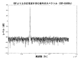
HFRの主要な問題は、オーディオ信号が、現行のHFR法では再構成することが難しいが、他の手段、例えば波形符号化法によって、又は合成信号生成によってより容易に再生することのできる、より高い周波数の成分を含むことがあることである。簡単な例として、COFより上の一つの正弦波からのみ成る信号の符号化がある(図1)。ここでCOFは5.5kHzである。低周波には利用可能な有用な信号が無いので、低帯域の外挿に基づいて広帯域を得るHFR法では、いかなる信号も生成されない。したがって、正弦波信号を再構成することができない。この信号を有効に符号化するために他の手段が必要である。この単純な例では、COFの柔軟な調整を達成するHFRシステムが、すでに該問題をある程度解決することができている。COFを正弦波の周波数より上に設定すると、コアコーダを使用して信号を非常に効率的に符号化することができる。しかし、これは、そうすることが可能であることを前提としており、いつもそうであるとは限らない。先に述べた通り、HFRをオーディオ符号化と組み合わせる利点は、コアコーダを半分のサンプリングレートで動作することができる(より高い圧縮効果をもたらす)ということである。コアが22.05kHzで動作する44.1kHzのシステムなどの現実的なシナリオでは、そのようなコアコーダは約10.5kHzまでの信号しか符号化することができない。しかし、それとは別に、該問題は、より多くの複素信号を考慮する場合には、コアコーダの範囲内のスペクトルの部分に対してさえも相当複雑になる。現実の信号は、例えば複素スペクトル内の高周波の可聴正弦波状成分(例えば小さいベル)を含むことがある(図2)。この場合、HFR法によって達成される利得の大半は、スペクトルのずっと大きい部分にコアコーダを使用することによって減殺されるので、COFの調整は解決にならない。 A major problem with HFR is that the audio signal is more difficult to reconstruct with current HFR methods, but can be more easily reproduced by other means such as waveform coding or by synthetic signal generation. It may contain high frequency components. A simple example is the encoding of a signal consisting only of one sine wave above the COF (FIG. 1). Here, the COF is 5.5 kHz. Since there is no useful signal available at low frequencies, the HFR method, which obtains a wide band based on extrapolation of the low band, does not generate any signal. Therefore, the sine wave signal cannot be reconstructed. Other means are required to effectively encode this signal. In this simple example, an HFR system that achieves flexible adjustment of COF has already been able to solve the problem to some extent. If the COF is set above the frequency of the sine wave, the core coder can be used to encode the signal very efficiently. However, this assumes that it is possible to do so and is not always so. As mentioned earlier, the advantage of combining HFR with audio coding is that the core coder can operate at half the sampling rate (providing a higher compression effect). In realistic scenarios, such as a 44.1 kHz system where the core operates at 22.05 kHz, such a core coder can only encode signals up to about 10.5 kHz. Apart from that, however, the problem becomes considerably more complex even for parts of the spectrum within the core coder when more complex signals are considered. Real signals may include, for example, high frequency audible sinusoidal components (eg, small bells) in the complex spectrum (FIG. 2). In this case, the COF adjustment is not a solution because most of the gain achieved by the HFR method is attenuated by using a core coder for a much larger portion of the spectrum.
発明の要約
したがって、上述した問題の解決策及び本発明の主題は、COFを変更させることができるだけでなく、異なる方法の周波数選択的複合によって復号化/再構成されたスペクトルをずっと柔軟に複合することもできる、非常に柔軟なHFRシステムの概念である。
SUMMARY OF THE INVENTION Therefore, the solution to the above-mentioned problem and the subject matter of the present invention not only can change the COF, but also much more flexibly compound the spectrum decoded / reconstructed by different methods of frequency selective combining. It is also a very flexible HFR system concept.
本発明の基本は、異なる符号化又は再構成方法を周波数に依存して選択することを可能にするHFRシステムのメカニズムである。これは、例えばSBRで使用されるような64帯域フィルタバンク解析/合成システムにより行なうことができる。エイリアスの無い等化機能を達成する複素フィルタバンクは特に有益になり得る。 The basis of the present invention is the mechanism of the HFR system that allows different coding or reconstruction methods to be selected depending on the frequency. This can be done, for example, by a 64-band filter bank analysis / synthesis system such as that used in SBR. Complex filter banks that achieve an alias-free equalization function can be particularly beneficial.
主要な進歩性は、フィルタバンクが今やCOFや次に続く包絡調整のためのフィルタとして働くだけではないことにある。それはまた、各々のフィルタバンクチャネルの入力を以下のソースから非常に柔軟に選択するためにも使用される。
波形符号化(コアコーダを使用する);
転置(次に続く包絡調整による);
波形符号化(ナイキストを超えた追加符号化を使用する);
パラメータ符号化;
スペクトルの特定部分で適用可能ないずれかの他の符号化/再構成方法;
又は、それらの任意の組合せ。
The main inventive step is that the filter bank now not only acts as a filter for COF and subsequent envelope adjustment. It is also used to select the input of each filter bank channel very flexibly from the following sources:
Waveform coding (using a core coder);
Transpose (by subsequent envelope adjustment);
Waveform coding (use additional coding over Nyquist);
Parameter encoding;
Any other encoding / reconstruction method applicable in a specific part of the spectrum;
Or any combination thereof.
したがって、今や、最高の可能な品質及び符号化利得を達成するために、任意のスペクトル構成において波形符号化、他の符号化方法及びHFR再構成を使用することができる。しかし、本発明がサブバンドフィルタバンクの使用に限定されず、言うまでもなく任意の周波数選択的フィルタリングでも使用できることは明白である。 Thus, waveform coding, other coding methods and HFR reconstruction can now be used in any spectral configuration to achieve the highest possible quality and coding gain. However, it is obvious that the present invention is not limited to the use of a subband filter bank, and of course can be used with any frequency selective filtering.
本発明は次の特徴を含む。
復号器で利用可能な低帯域を利用して高帯域を外挿するHFR方法;
符号器側で、COFより低い周波数範囲に基づいては、HFR方法が原信号の単一又は複数のスペクトル線と同様の単一又は複数のスペクトル線を正しく生成しない異なる周波数領域内で、評価するためにHFR方法を使用すること;
その異なる周波数領域に対して、単一又は複数のスペクトル線を符号化すること;
その異なる周波数領域に対し符号化された単一又は複数のスペクトル線を符号器から復号器へ送信すること;
その単一又は複数のスペクトル線を復号すること;
復号された単一又は複数のスペクトル線を復号器におけるHFR方法からの出力の各周波数領域に加えること;
その符号化は前記単一又は複数のスペクトル線のパラメータ符号化である;
その符号化は前記単一又は複数のスペクトル線の波形符号化である;
パラメータ符号化された単数又は複数のスペクトル線がサブバンドフィルタバンクを用いて合成される;
単一又は複数のスペクトル線の波形符号化は、ソース符号化システムの基礎を成すコアコーダによって行なわれる;
単数又は複数のスペクトル線の波形符号化は、任意の波形コーダによって行なわれる。
The present invention includes the following features.
An HFR method for extrapolating the high band using the low band available at the decoder;
On the encoder side, based on a frequency range below the COF, the HFR method evaluates in different frequency regions that do not correctly generate single or multiple spectral lines similar to the single or multiple spectral lines of the original signal Using the HFR method for;
Encoding single or multiple spectral lines for the different frequency regions;
Transmitting from the encoder to the decoder single or multiple spectral lines encoded for the different frequency domains;
Decoding the single or multiple spectral lines;
Applying the decoded single or multiple spectral lines to each frequency domain of the output from the HFR method at the decoder;
The encoding is a parameter encoding of the single or multiple spectral lines;
The encoding is a waveform encoding of the single or multiple spectral lines;
One or more spectrally encoded spectral lines are synthesized using a subband filter bank;
Waveform coding of single or multiple spectral lines is performed by the core coder underlying the source coding system;
The waveform encoding of one or more spectral lines is performed by an arbitrary waveform coder.
本発明を今から、発明の範囲又は精神を限定するのではなく、例証として、添付の図面に関連して説明する。 The present invention will now be described, by way of example, with reference to the accompanying drawings, rather than limiting the scope or spirit of the invention.
好適な実施形態の説明
以下で述べる実施形態は、高周波再構成システムの改善のための本発明の原理の単なる例証である。ここに記載する構成及び詳細の修正及び変形が当業者には明白であることが理解される。したがって、本発明は本書に記載する特許請求の範囲によってのみ限定されるものであって、本書で実施形態の記述及び説明によって提示する特定の詳細によって限定するつもりはない。
DESCRIPTION OF THE PREFERRED EMBODIMENTS The embodiments described below are merely illustrative of the principles of the present invention for improving a high frequency reconstruction system. It will be understood that modifications and variations in the arrangements and details described herein will be apparent to those skilled in the art. Accordingly, the present invention is limited only by the claims set forth herein, and is not intended to be limited by the specific details presented herein by the description and description of the embodiments.
図9は本発明の符号器を示す。符号器はコアコーダ702を含む。ここで、本発明の方法は、既存のコアコーダ用のいわゆるアドオンモジュールとして使用することもできることに留意されたい。この場合、本発明の符号器は、別個の独立コアコーダ702によって出力される符号化された入力信号を受け取るための入力を含む。
FIG. 9 shows the encoder of the present invention. The encoder includes a
図9の本発明の符号器はさらに高周波再生ブロック703c、差検出器703a、差記述装置ブロック703b、及びコンバイナ705を含む。
The encoder of the present invention of FIG. 9 further includes a high
以下では、上述した手段の機能的相互依存関係について説明する。 Below, the functional interdependence of the above-mentioned means will be described.
特に、本発明の符号器は、オーディオ信号入力900に入力されるオーディオ信号を符号化して符号化信号を得るためのものである。その符号化信号は、予め定められた周波数より低い周波数成分に基づき、クロスオーバ周波数とも呼ばれる予め定められた周波数より上の周波数成分を生成するのに適した高周波再生技術を使用して復号するように意図されている。
In particular, the encoder of the present invention is for encoding an audio signal input to the
ここで、高周波再生技術として、最近公知となった広範囲の様々な技術を使用できることに留意されたい。これに関して、用語「周波数成分」は広い意味に理解されたい。この用語は少なくとも、FFT、MDCT、又は何か別のものなどの時間領域/周波数領域変換によって得られるスペクトル係数を含む。また、用語「周波数成分」は帯域通過信号、すなわち低域通過フィルタ、帯域通過フィルタ、又は高域通過フィルタなどの周波数選択フィルタの出力で得られる信号をも含む。 It should be noted here that a wide variety of techniques that have recently become known can be used as the high-frequency reproduction technique. In this regard, the term “frequency component” should be understood in a broad sense. The term includes at least spectral coefficients obtained by time domain / frequency domain transforms such as FFT, MDCT, or something else. The term “frequency component” also includes a band-pass signal, that is, a signal obtained at the output of a frequency selective filter such as a low-pass filter, a band-pass filter, or a high-pass filter.
コアコーダ702が本発明の符号器の一部であるか否か、あるいは本発明の符号器が既存のコアコーダのアドオンモジュールとして使用されるか否かの事実に関係なく、本発明の符号器は、入力信号の符号化表現でありかつ符号化アルゴリズムを用いて符号化された、符号化入力信号を提供するための手段を含む。これに関連して、入力信号は予め定められた周波数より低い、すなわちいわゆるクロスオーバ周波数より低いオーディオ信号の周波数成分を表わすことに注意されたい。入力信号の周波数成分がオーディオ信号の低域部だけを含むことを示すために、図9には低域通過フィルタ902が示されている。本発明の符号器は実際、そのような低域通過フィルタを持つことができる。また、そのような低域通過フィルタはコアコーダ702内に含めることができる。また、コアコーダは他の公知の手段によってオーディオ信号の周波数帯域を廃棄する機能を実行することができる。
Regardless of whether the
コアコーダ702の出力には、符号化された入力信号が存在し、それは、その周波数成分に関して入力信号に似ているが、符号化入力信号が予め定められた周波数より上の周波数成分を含まない点で、オーディオ信号とは異なる。
There is an encoded input signal at the output of the
高周波再生ブロック703cは、入力信号、すなわちコアコーダ702に入力された信号に対し、又はその符号化されかつ再び復号された信号に対し、高周波再生技術を実行するためのものである。上記の復号された信号を選択する場合、本発明の符号器は、コアコーダから符号化入力信号を受け取り、かつ、低ビットレートで送信された符号化信号に対してオーディオ帯域幅に向上させる高周波再生技術が実行される復号器/受信器側に存在するのと全く同じ状況が得られるように、この信号を復号するコア復号器903をも含む。
The high
HFRブロック702は、予め定められた周波数より上の周波数成分を含む再生信号を出力する。
The
図9に示す通り、HFRブロック703cによって出力される再生信号は、差検出手段703aに入力される。他方、差検出手段は、オーディオ信号入力900に入力される原オーディオ信号をも受け取る。HFRブロック703cからの再生信号と入力900からのオーディオ信号との間の差を検出するための該手段は、予め定められた有意しきい値を超えるこれらの信号間の差を検出するように構成されている。有意しきい値として機能する好適なしきい値の幾つかの例については後述する。
As shown in FIG. 9, the reproduction signal output by the
差検出器の出力は、差記述装置ブロック703bの入力に接続される。差記述装置ブロック703bは、検出された差を特定の方法で記述して検出された差に関する追加情報を得るためのものである。これらの追加情報はコンバイナ手段705に入力するのに適したものであり、コンバイナ手段705は符号化入力信号、その追加情報、及び受信器へ送信されるかあるいは記憶媒体に格納される符号化信号を得るために生成することのできる幾つかの他の信号を結合する。追加情報の顕著な一例は、スペクトル包絡推定器704によって生成されるスペクトル包絡情報である。スペクトル包絡推定器704は、予め定められた周波数より上、すなわちクロスオーバ周波数より上のオーディオ信号のスペクトル包絡情報を提供するために構成されている。このスペクトル包絡情報は、復号器側のHFRモジュールで、予め定められた周波数より上の復号オーディオ信号のスペクトル成分を合成するために使用される。
The output of the difference detector is connected to the input of the difference
本発明の好適な実施形態では、スペクトル包絡推定器704は、スペクトル包絡の粗な表現のみを提供するために構成されている。特に、各スケールファクタ帯域に対しスペクトル包絡値を一つだけ提供することが好ましい。スケールファクタ帯域の使用は当業者には公知である。MP3又はMPEG−AACなどの変換コーダに関しては、スケールファクタ帯域はいくつかのMDCT線を含む。どのスペクトル線がどのスケールファクタ帯域に属するかの詳細な編成は標準化されているが、変更することができる。一般的に、スケールファクタ帯域は幾つかのスペクトル線(例えばMDCT線;ここでMDCTとは変形離散コサイン変換の略である)、又は帯域通過信号を含み、その数はスケールファクタ帯域毎に異なる。一般的に、一つのスケールファクタ帯域は少なくとも3つ以上、通常は10又は20を超えるスペクトル線又は帯域通過信号を含む。
In the preferred embodiment of the present invention, the
本発明の好適な実施形態では、本発明の符号器はさらに可変クロスオーバ周波数を含む。クロスオーバ周波数の制御は本発明の差検出器703aによって行なわれる。制御は、より高いクロスオーバ周波数がHFRによって生成されるアーチファクトを低減するのに非常に貢献するという結論に差検出器が達した場合に、差検出器が符号化入力信号の帯域幅を拡張するためにコアコーダ702のみならず低域通過フィルタ902及びスペクトル包絡推定器704にもクロスオーバ周波数をより高い周波数にするように指示することができるように構成されている。
In a preferred embodiment of the present invention, the encoder of the present invention further includes a variable crossover frequency. The control of the crossover frequency is performed by the
他方、検出器は、クロスオーバ周波数より低い特定の帯域幅が音響的に重要でなく、かつ、したがってコアコーダによって直接符号化しなければならないというよりむしろ、復号器でHFR合成によって容易に生成することができることが判明した場合、クロスオーバ周波数を低減するように構成することもできる。 On the other hand, the detector can be easily generated by HFR synthesis at the decoder, rather than having a specific bandwidth below the crossover frequency acoustically insignificant and therefore must be encoded directly by the core coder. If found to be possible, it can also be configured to reduce the crossover frequency.
クロスオーバ周波数を低下することによって節約されるビットは、他方ではクロスオーバ周波数を増加しなければならない場合に使用することができるので、心理音響コーティング法に対して知られている一種のビット節約オプションを得ることができる。これらの方法では、符号化しやすい、すなわちアーチファクト無しで符号化するために低い数のビットしか必要でない白ノイズ信号部分も信号に存在し、かつ白ノイズ信号部分は特定のビット節約制御によって認識される場合には、他方では、符号化することが難しい、すなわちアーチファクトなしに符号化するために多数のビットを必要とする主にトーナルな成分により多くのビットを使用することができる。 A bit saving option known for psychoacoustic coating methods, since the bits saved by lowering the crossover frequency can be used on the other hand if the crossover frequency has to be increased Can be obtained. In these methods, there is also a white noise signal part that is easy to encode, i.e., only a low number of bits are required to encode without artifacts, and the white noise signal part is recognized by a specific bit saving control. In some cases, on the other hand, more bits can be used for primarily tonal components that are difficult to encode, ie, require a large number of bits to encode without artifacts.
要約すると、クロスオーバ周波数制御は、差検出器によって行なわれる検出結果に応じて、予め定められた周波数すなわちクロスオーバ周波数を増加又は減少するように構成される。差検出器は、一般に、復号器における実際の状況をシミュレートするために、HFRブロック703cの効率及び性能を評価する。
In summary, the crossover frequency control is configured to increase or decrease a predetermined frequency, ie, the crossover frequency, depending on the detection result performed by the difference detector. The difference detector typically evaluates the efficiency and performance of the
差検出器703aは、再生信号に含まれないオーディオ信号のスペクトル線を検出するように構成されることが好ましい。これを行なうために、差検出器は、再生信号及びオーディオ信号について予測動作を実行するための予測器と、再生信号及びオーディオ信号に対して得られた予測利得における差を決定するための手段とを含むことが好ましい。特に、再生信号又はオーディオ信号の周波数関連部分のうち、予測器利得における差がこの好適な実施形態における有意しきい値である利得しきい値より大きいものを決定する。
The
ここで、差検出器703aは好ましくは、一方で再生信号及び他方でオーディオ信号において対応する周波数帯域を評価するという意味で、周波数選択的要素として働くことに注意されたい。このために、差検出器は、オーディオ信号及び再生信号を変換するための時間−周波数変換要素を含むことができる。本発明に適用される好適な高周波再生方法の場合のように、HFRブロック703cによって生成される再生信号がすでに周波数関連表現として存在する場合、そのような時間領域/周波数領域変換手段は必要ない。
It should be noted here that the
通常時間領域信号であるオーディオ信号を変換する場合のように、時間領域−周波数領域変換要素を使用しなければならない場合、フィルタバンク手法が好適である。解析フィルタバンクは適切な寸法の隣接帯域通過フィルタの列を含み、各帯域通過フィルタはそれぞれの帯域通過フィルタの帯域幅によって定義される帯域幅を有する帯域通過信号を出力する。帯域通過フィルタ信号は、その導出元の信号に比較して制限帯域幅を有する時間領域信号と解釈することができる。帯域通過信号の中心周波数は、当業界で既知の通り、解析フィルタバンクのそれぞれの帯域通過フィルタの位置によって定義される。 The filter bank approach is preferred when time domain-frequency domain transform elements must be used, such as when transforming audio signals that are normally time domain signals. The analysis filter bank includes a series of appropriately sized adjacent bandpass filters, each bandpass filter outputting a bandpass signal having a bandwidth defined by the bandwidth of the respective bandpass filter. The bandpass filter signal can be interpreted as a time domain signal having a limited bandwidth compared to the signal from which it is derived. The center frequency of the bandpass signal is defined by the position of each bandpass filter in the analysis filter bank, as is known in the art.
後述する通り、有意しきい値を超える差を決定するための好適な方法は、トーナリティ尺度と、特にトーナル対雑音比に基づく決定である。そのような方法は信号におけるスペクトル線、又は信号における雑音部分を安定かつ効率的に見つけ出すのに適しているからである。 As will be described later, the preferred method for determining the difference above the significance threshold is a determination based on the tonality measure and in particular the tonal-to-noise ratio. This is because such a method is suitable for finding a spectral line in a signal or a noise portion in a signal stably and efficiently.
符号化すべきスペクトル線の検出
HFR後に復号された出力で紛失しているスペクトル線を符号化することができるようにするために、符号器でこれらを検出することが不可欠である。これを達成するために、後続復号器HFRの適切な合成を符号器で実行する必要がある。これは、この合成の出力が復号器のそれと同様の時間領域出力信号である必要があることを意味しない。復号器でHFRの絶対スペクトル表現を観察しかつ合成すれば十分である。これは、QMFフィルタバンクにおける予測と、その後の原信号とHFR対応物との間の予測利得における差のピーク選定を使用することによって達成することができる。予測利得における差のピーク選定の代わりに、絶対スペクトルの差も使用できる。どちらの方法の場合も、成分の周波数分布についてHFRが復号器で行なうものと同様の再構成を単に行なうことによって、HFRの周波数依存性予測利得又は絶対スペクトルが合成される。
Detection of spectral lines to be encoded In order to be able to encode missing spectral lines in the output decoded after HFR, it is essential to detect these at the encoder. In order to achieve this, an appropriate synthesis of the subsequent decoder HFR needs to be performed at the encoder. This does not mean that the output of this synthesis needs to be a time domain output signal similar to that of the decoder. It is sufficient to observe and synthesize the absolute spectral representation of the HFR at the decoder. This can be achieved by using prediction in the QMF filter bank and subsequent peak selection of the difference in prediction gain between the original signal and the HFR counterpart. Instead of differential peak selection in the predicted gain, absolute spectral differences can also be used. In both methods, the frequency dependent prediction gain or absolute spectrum of the HFR is synthesized by simply performing a reconstruction similar to that performed by the HFR on the frequency distribution of the components.
ひとたび原信号及び合成HFR信号という二つの表現が得られると、幾つかの方法で検出を行なうことができる。 Once two representations are obtained, the original signal and the synthesized HFR signal, detection can be performed in several ways.
QMFフィルタバンクでは、様々なチャネルに対して低次の線形予測、例えば二次LPC(LPC-order 2)を実行することができる。予測された信号のエネルギ及び信号の総エネルギが与えられると、次式に従ってトーナル対雑音比を定義することができる。

上記の検出は、原信号の任意のスペクトル表現と合成HFR出力、例えば絶対スペクトルのピーク選定[「Extraction of spectral peak parameters using a short-time Fourier transform modeling [sic] and no sidelobe windows」,Ph Depalle, T Helie, IRCAM]又は同様の方法を、使用し、次いで原信号で検出されたトーナル成分と合成HFR出力で検出された成分とを比較して実行することもできる。 The above detection involves arbitrary spectral representation of the original signal and synthesized HFR output, eg peak selection of the absolute spectrum ["Extraction of spectral peak parameters using a short-time Fourier transform modeling [sic] and no sidelobe windows", Ph Depalle, T Helie, IRCAM] or similar method can be used, and then performed by comparing the tonal component detected in the original signal with the component detected in the synthesized HFR output.
HFR出力からスペクトル線が紛失していると思われる場合、効率的に符号化し、復号器に送信し、HFR出力に追加する必要がある。インタリーブ波形符号化、又は例えばスペクトル線のパラメータ符号化など、幾つかの手法を使用することができる。 If spectral lines appear to be missing from the HFR output, they need to be efficiently encoded, transmitted to the decoder, and added to the HFR output. Several approaches can be used, such as interleaved waveform coding or, for example, spectral line parameter coding.
QMF/ハイブリッドフィルタバンク、インタリーブ波形符号化
符号化すべきスペクトル線がコアコーダのFS/2より下にある場合、そのスペクトル線はそのコアコーダによって符号化することができる。これは、コアコーダがCOFまでの周波数範囲全体、及び復号器でHFRによって再生されないトーナル成分の周囲の定義された周波数範囲を符号化することを意味する。また、トーナル成分は任意の波形コーダによって符号化することができ、この方法では、システムはコアコーダのFS/2によって制限されず、原信号の周波数範囲全体に対して動作することができる。
QMF / Hybrid filter bank, interleaved waveform coding If the spectral line to be encoded is below the FS / 2 of the core coder, the spectral line can be encoded by the core coder. This means that the core coder encodes the entire frequency range up to the COF and the defined frequency range around the tonal component that is not reproduced by the HFR at the decoder. Also, the tonal component can be encoded by an arbitrary waveform coder, and in this way the system is not limited by the FS / 2 of the core coder and can operate over the entire frequency range of the original signal.
この目的のために、コアコーダ制御装置910が本発明の符号器に設けられる。差検出器703aが、予め定められた周波数より上であるがサンプリング周波数の値の半分(FS/2)より下の有意のピークを確定する場合、コアコーダ制御装置910がコアコーダ702にオーディオ信号から導出された帯域通過信号をコア符号化させる。その帯域通過信号の周波数帯域はそのスペクトル線が検出された周波数を含み、実際の実現によっては、その検出されたスペクトル線を埋め込む特定の周波数帯域をも含む。この目的のために、コアコーダ702自体又はコアコーダ内の制御可能な帯域通過フィルタが、破線912によって示されるようにコアコーダに直接送られるオーディオ信号から関連部分をフィルタリングする。
For this purpose, a
この場合、コアコーダ702は、差検出器によって検出されたクロスオーバ周波数を超えるスペクトル線を符号化するという意味で、差記述装置703bとして働く。したがって、差記述装置703bによって得られる追加情報は、予め定められた周波数より上であるがサンプリング周波数の値の半分(FS/2)より低いオーディオ信号の特定の帯域に関連する、コアコーダ702によって出力される符号化信号に対応する。
In this case, the
前述した周波数スケジューリングをより分かりやすく解説するために、図11を参照して説明する。図11は、0の周波数から始まり、図11の右に向かって伸びる周波数スケールを示す。特定の周波数値で、クロスオーバ周波数とも呼ばれる予め定められた周波数1100を見ることができる。この周波数より下では、図9のコアコーダ702が符号化入力信号を生成するように作動する。その予め定められた周波数より上では、スペクトル包絡推定器704だけが作動して、例えば各スケールファクタ帯域に一つのスペクトル包絡が得られる。図11から、スケールファクタ帯域は、公知の変換コーダの場合、周波数係数又は帯域通過信号に対応する幾つかのチャネルを含むことが明らかになる。図11はまた、後述する図12の合成フィルタバンクからの合成フィルタバンクチャネルを示すのにも有用である。また、サンプリング周波数の値の半分FS/2も示されており、それは図11の場合、その予め定められた周波数より上にある。
In order to explain the above-described frequency scheduling more easily, it will be described with reference to FIG. FIG. 11 shows a frequency scale that starts at a frequency of 0 and extends to the right of FIG. At a particular frequency value, a
検出されたスペクトル線がFS/2より上にある場合、コアコーダ702は差記述装置703bとして働くことができない。この場合、上述した通り、差記述装置では、オーディオ信号のうち通常のHFR技法では再生されないスペクトル線に関する追加情報を符号化/獲得するために、完全に異なる符号化アルゴリズムを適用しなければならない。
If the detected spectral line is above FS / 2, the
以下では、図10を参照しながら、符号化信号を復号するための本発明の復号器について説明する。符号化信号は入力1000でデータストリームデマルチプレクサ801に入力される。特に、符号化信号は、原オーディオ信号(図9の入力900に入力されたもの)の予め定められた周波数より下の周波数成分を表わす符号化入力信号(図9のコアコーダ702から出力されたもの)を含む。原信号の符号化は、特定の既知の符号化アルゴリズムを使用してコアコーダ702で実行された。入力1000の符号化信号は、再生信号と原オーディオ信号との間の検出された差を記述する追加情報を含む。その再生信号とは入力信号又はその符号化され復号された信号(図9のコアデコーダ903による実施形態)から高周波再生技術(図9のHFRブロック703cに実現される)によって生成されたものである。
Hereinafter, the decoder of the present invention for decoding an encoded signal will be described with reference to FIG. The encoded signal is input to
特に、本発明の復号器は、符号化アルゴリズムに従って符号化入力信号を復号することによって生成される復号入力信号を得るための手段を含む。この目的のために、本発明の復号器は、図10に示すようにコアデコーダ803を含むことができる。また、本発明の復号器は、復号入力信号を得るための手段が図10に示すようにその後に配置されたHFRブロック804の特定の入力を使用することによって実現されるように、既存のコアコーダへのアドオンモジュールとして使用することもできる。本発明の復号器はまた、図9に示した差記述装置703bによって生成された追加情報に基づいて、検出された差を再構成するための再構成装置をも含む。
In particular, the decoder of the present invention includes means for obtaining a decoded input signal generated by decoding the encoded input signal according to an encoding algorithm. For this purpose, the decoder of the present invention can include a
主要構成要素として、本発明の復号器はさらに、図9に示すようにHFRブロック703cによって実現された高周波再生技術と同様の高周波再生技術を実行するための高周波再生手段を含む。高周波再生ブロックは再生信号を出力し、それは通常のHFR復号器において、符号器で廃棄されたオーディオ信号のスペクトル部分を合成するために使用される。
As a main component, the decoder of the present invention further includes a high frequency reproduction means for executing a high frequency reproduction technique similar to the high frequency reproduction technique realized by the
本発明では、図8のブロック806及び807の機能性を含む生成装置を設けるので、生成装置によって出力されるオーディオ信号は、高周波再構成部分を含むだけでなく、検出された差、好ましくは、HFRブロック804では合成することができないが原オーディオ信号に存在していたスペクトル線をも含む。
In the present invention, a generator is provided that includes the functionality of
後述するように、生成装置806、807は、HFRブロック804によって出力された再生信号を使用し、それを単に、コアコーダ803によって出力された低帯域復号信号と結合し、次いで追加情報に基づいてスペクトル線を挿入することができる。また、好ましくは、生成装置は、図12に関連して概説するように、HFR生成スペクトル線の多少の操作をも行なう。一般的に、生成装置は単にスペクトル線をHFRスペクトルの特定の周波数位置に挿入するだけでなく、挿入されるスペクトル線付近の減衰HFR再生スペクトル線における挿入スペクトル線のエネルギをも考慮する。
As will be described later, the
上記の処置は、符号器で実行されるスペクトル包絡パラメータ推定に基づく。スペクトル線が配置される予め定められた周波数すなわちクロスオーバ周波数より上のスペクトル帯域で、スペクトル包絡推定器はこの帯域のエネルギを推定する。そのような帯域は例えばスケールファクタ帯域である。スペクトル包絡推定器は、エネルギが雑音性スペクトル線又は特定の顕著なピークすなわちトーナルスペクトル線のどちらに由来するかに関係なく、この帯域のエネルギを蓄積するので、所定のスケールファクタ帯域のスペクトル包絡推定は、所定のスケールファクタ帯域の「雑音性」スペクトル線のエネルギのみならず、スペクトル線のエネルギをも含む。 The above procedure is based on spectral envelope parameter estimation performed at the encoder. In a spectral band above the predetermined frequency at which the spectral line is located, ie the crossover frequency, the spectral envelope estimator estimates the energy in this band. Such a band is, for example, a scale factor band. The spectral envelope estimator accumulates energy in this band regardless of whether the energy originates from a noisy spectral line or a particular prominent peak or tonal spectral line, so that a spectral envelope estimate for a given scale factor band Includes not only the energy of “noisy” spectral lines of a given scale factor band, but also the energy of spectral lines.
符号化信号に関連して送信されるスペクトルエネルギ推定情報をできるだけ正確に使用するために、本発明の復号器は、所定のスケールファクタ帯域における付近の「雑音性」スペクトル線のみならず挿入スペクトル線をも調整することによって符号器におけるエネルギ蓄積方法を考慮するので、総エネルギすなわちこの帯域の全ての線のエネルギが、このスケールファクタ帯域の送信スペクトル包絡の推定によって決定されるエネルギに対応する。 In order to use the spectral energy estimation information transmitted in association with the encoded signal as accurately as possible, the decoder of the present invention uses not only the nearby “noisy” spectral lines in a given scale factor band, but also the inserted spectral lines. The total energy, ie the energy of all lines in this band, corresponds to the energy determined by the estimation of the transmission spectrum envelope of this scale factor band.
図12は、解析フィルタバンク1200及び合成フィルタバンク1202に基づく好適なHFR再構成のための略図を示す。解析フィルタバンクは合成フィルタバンクと同様に、スケールファクタ帯域及び予め定められた周波数に関連して図11に示した通り、幾つかのフィルタバンクチャネルから構成される。図12に1204で示した予め定められた周波数より上のフィルタバンクチャネルは、フィルタバンク信号、すなわち図12に線1206で示す通り、予め定められた周波数より下のフィルタバンクチャネルによって再構成しなければならない。ここで、各フィルタバンクチャネルには、複素帯域通過信号サンプルを有する帯域通過信号が存在することに注目されたい。図10の高周波再構成ブロック804は、かつ図9のHFRブロック703cも、特定のHFRアルゴリズムに関連してHFRを行なうように構成された転置/包絡調整モジュール1208を含む。符号器側のブロックは必ずしも包絡調整モジュールを含む必要がないことに注目されたい。トーナリティ尺度は周波数の関数として推定することが好ましい。そうすると、トーナリティの差が大きすぎるときに、絶対スペクトル包絡の差は無関係である。
FIG. 12 shows a schematic diagram for a preferred HFR reconstruction based on
HFRアルゴリズムは純調波又は近似調波HFRアルゴリズムとすることができ、あるいは、予め定められ周波数より下の幾つかの連続解析フィルタバンクチャネルから予め定められた周波数より上の特定の連続合成フィルタバンクチャネルへの転置を含む、低複雑性HFRアルゴリズムとすることができる。さらに、ブロック1208は、一つのスケールファクタ帯域における調整スペクトル線の蓄積エネルギが例えばそのスケールファクタ帯域のスペクトル包絡値と一致するように、転置されるスペクトル線の大きさを調整するように包絡調整関数を含むことが好ましい。
The HFR algorithm can be a pure harmonic or an approximate harmonic HFR algorithm, or a specific continuous synthesis filter bank above a predetermined frequency from several continuous analysis filter bank channels below a predetermined frequency. It can be a low complexity HFR algorithm that includes transposition to a channel. Further,
図12から、一つのスケールファクタ帯域が幾つかのフィルタバンクチャネルを含むことが明らかになる。一例のスケールファクタ帯域はフィルタバンクチャネルllowからフィルタバンクチャネルlupまで広がる。 From FIG. 12, it becomes clear that one scale factor band includes several filter bank channels. An example scale factor band extends from filter bank channel l low to filter bank channel l up .
その後の適応/正弦波挿入法に関して、ここで、この適応又は「操作」が、HFR生成帯域通過信号を操作するためのマニピュレータ1210を含む図10の生成装置806、807によって行なわれることに留意されたい。このマニピュレータ1210は、入力として、図10の再構成装置805から少なくとも線の位置、すなわち好ましくは、合成される正弦波が配置される番号lsを受け取る。さらに、マニピュレータ1210はこのスペクトル線(正弦波)に対する適切なレベル、及び好ましくは所定のスケールファクタ帯域sfb1212の総エネルギに関する情報をも受け取ることが好ましい。
Regarding the subsequent adaptive / sinusoidal insertion method, it is noted here that this adaptation or “manipulation” is performed by the
ここで、合成正弦波信号が挿入される特定のチャネルlsが、後述するように所定のスケールファクタ帯域1212の他のチャネルとは異なる処理を受けることに注目されたい。ブロック1208によって出力されるHFR再生チャネル信号の「処理」は、上述したように、図10の生成装置806、807の一部であるマニピュレータ1210によって行なわれる。
Here, it should be noted that the specific channel l s into which the synthesized sine wave signal is inserted is subjected to processing different from other channels of the predetermined
スペクトル線のパラメータ符号化
紛失スペクトル線のパラメータ符号化を使用するフィルタバンクをベースとするシステムの一例を以下で概説する。
Spectral Line Parameter Coding An example of a filter bank based system that uses missing spectral line parameter coding is outlined below.
システムが[PCT/SE00/00159]による適応ノイズフロア追加を使用するHFR法を使用する場合、スペクトル線のレベルは包絡データ及びノイズフロアデータによって与えられるので、紛失スペクトル線の周波数位置だけを符号化する必要がある。所定のスケールファクタ帯域の総エネルギはエネルギデータによって与えられ、トーナル/雑音エネルギ比はノイズフロアレベルのデータによって与えられる。さらに、ヒトの聴覚系の周波数分解能は高い周波数では粗くなるので、高周波領域ではスペクトル線の厳密な位置はあまり重要でない。これは、各スケールファクタ帯域について復号器でその特定の帯域に正弦波を加えるべきかどうかを示すベクトルは必須であるが、それにより、スペクトル線を非常に効率的に符号化できることを暗に示している。 When the system uses the HFR method with adaptive noise floor addition according to [PCT / SE00 / 00159], the spectral line level is given by the envelope data and noise floor data, so only the frequency position of the missing spectral line is encoded. There is a need to. The total energy for a given scale factor band is given by the energy data and the tonal / noise energy ratio is given by the noise floor level data. Furthermore, since the frequency resolution of the human auditory system is coarse at high frequencies, the exact position of the spectral lines is not very important in the high frequency region. This implies that for each scale factor band, a vector indicating whether the decoder should add a sine wave to that particular band is mandatory, but that it can encode spectral lines very efficiently. ing.
復号器でスペクトル線は数通りの方法で生成することができる。一つの手法は、HFR信号の包絡調整にすでに使用されているQMFフィルタバンクを利用する。隣接チャネルにエイリアシングを発生させないためにサブバンドフィルタバンクをフィルタチャネルの真ん中に配置することを前提として、サブバンドフィルタバンクで正弦波を生成することが簡単なので、この手法は非常に効率的である。スペクトル線の周波数位置は通常粗く量子化されるので、これは厳しい制約ではない。 Spectral lines can be generated by the decoder in several ways. One approach utilizes a QMF filter bank that has already been used to adjust the envelope of the HFR signal. This technique is very efficient because it is easy to generate a sine wave in the subband filter bank, assuming that the subband filter bank is placed in the middle of the filter channel to avoid aliasing in adjacent channels . This is not a hard constraint since the frequency position of the spectral line is usually coarsely quantized.
符号器から復号器へ送られるスペクトル包絡データが時間的及び周波数的に、グループ化されたサブバンドフィルタバンクエネルギによって表わされる場合、所定の時間におけるスペクトル包絡ベクトルは、
![]()
![]()
![]()
![]()
ここで、エネルギ及びノイズフロアデータは、ベクトル
![]()
![]()
![]()
![]()
![]()
![]()
合成正弦波が一つのフィルタバンクチャネルで生成されると、これを、その特定のスケールファクタ帯域に含まれる全てのサブバンドフィルタバンクチャネルに対して考慮する必要がある。これがその周波数範囲のスペクトル包絡の最高周波数分解能であるためである。この周波数分解能はまた、HFRから紛失しているスペクトル線の周波数位置を指定するためにも使用され、出力に加える必要がある場合、これらの合成正弦波の生成及び補償は以下に従って行なうことができる。 When a composite sine wave is generated in one filter bank channel, this needs to be considered for all subband filter bank channels included in that particular scale factor band. This is because this is the highest frequency resolution of the spectral envelope in that frequency range. This frequency resolution is also used to specify the frequency position of the missing spectral line from the HFR, and if it needs to be added to the output, these composite sine waves can be generated and compensated according to the following: .
最初に、現行スケールファクタ帯域内の全てのサブバンドチャネルを、その帯域に対する平均エネルギが
ここで注目すべきことは、上の式が、番号lsを持つチャネルの帯域通過信号を除き、llowからlupまで広がる所定のスケールファクタ帯域のチャネルに対してのみ有効であるということである。番号lsの信号は以下の方程式グループによって処理される。 It should be noted here that the above equation is valid only for channels of a predetermined scale factor band extending from l low to l up except for the bandpass signal of the channel having the number l s. is there. Signal number l s is processed by the following equation group.
マニピュレータ1210は、チャネル番号lsを有するチャネルに対し、以下の式を実行する。すなわち、合成正弦波を表わす複素変調信号によって、チャネルlsの帯域通過信号を変調する。さらに、マニピュレータ1210は、合成正弦波調整係数gsineによって合成正弦波のレベルを決定するとともに、HFRブロック1208から出力されるスペクトル線の加重を実行する。したがって、以下の式は、正弦波が配置されるフィルタバンクチャネルlsに対してのみ有効である。
したがって、正弦波は、
上記のことは図4〜6に示されている。原信号のスペクトルが図4に示され、上記処理がある場合とない場合の出力のスペクトルが図5〜6に示されている。図5では、8kHz範囲のトーンが広帯域雑音によって置き換えられている。図6では、8kHz範囲のスケールファクタ帯域の真ん中に正弦波が挿入され、そのスケールファクタ帯域の正しい平均エネルギが維持されるように、スケールファクタ帯域全体のエネルギが調整されている。 The above is illustrated in FIGS. The spectrum of the original signal is shown in FIG. 4, and the spectrum of the output with and without the above processing is shown in FIGS. In FIG. 5, the tones in the 8 kHz range have been replaced by broadband noise. In FIG. 6, the energy of the entire scale factor band is adjusted so that a sine wave is inserted in the middle of the scale factor band in the 8 kHz range and the correct average energy of that scale factor band is maintained.
実用的実現
本発明は、任意のコーデックを使用するアナログ又はデジタルの信号の記憶又は送信用の様々な種類のシステム用に、ハードウェアチップ及びDSPのどちらでも実現することができる。図7に、本発明の可能な符号器の実現を示す。アナログ入力信号はデジタル信号に変換され(701)、HFR用のパラメータ抽出モジュール704のみならずコア符号器702にも送られる。復号器で高周波再構成後にどのスペクトル線が紛失するかを決定するために、解析が実施される(703)。これらのスペクトル線は適切な方法で符号化され、残りの符号化データと共にビットストリームに多重化される(705)。図8は、本発明の可能な復号器の実現を示す。ビットストリームは分離され(801)、低帯域がコア復号器803によって復号され、高帯域は適切なHFR装置804を用いて再構成され、HFR後に紛失するスペクトル線に関する追加情報が復号され(805)、紛失成分を再生するために使用される(806)。高帯域のスペクトル包絡は復号され(802)、再構築された広帯域のスペクトル包絡を調整するために使用される(807)。低帯域は、再構築された広帯域との正しい時間同期を確実にするために遅延され(808)、二つが共に加算される。デジタル広帯域信号がアナログ広帯域信号に変換される(809)。
Practical implementation The present invention can be implemented in both hardware chips and DSPs for various types of systems for storing or transmitting analog or digital signals using any codec. FIG. 7 shows a possible encoder implementation of the present invention. The analog input signal is converted into a digital signal (701) and sent to the
実現の細部において、符号化又は復号のための本発明の方法は、ハードウェア又はソフトウェアで実現することができる。実現は、対応する方法を実行するようにプログラム可能なコンピュータシステムと協調することのできる、電子的に読取可能な制御信号によりデジタル記憶媒体、特にディスク、CD上で行なうことができる。一般的に、本発明は、プログラム製品がコンピュータ上で作動するときに、本発明の方法を実行するために機械可読担体に格納されたプログラムコードを持つコンピュータプログラム製品にも関する。言い換えると、本発明はしたがって、コンピュータプログラムがコンピュータ上で作動するときに、符号化又は復号の本発明の方法を実行するためのプログラムコードを持つコンピュータプログラムである。 In implementation details, the inventive method for encoding or decoding can be implemented in hardware or software. Implementation can be performed on a digital storage medium, in particular a disc, CD, by means of electronically readable control signals that can be coordinated with a programmable computer system to carry out the corresponding method. In general, the invention also relates to a computer program product having program code stored on a machine-readable carrier for performing the method of the invention when the program product runs on a computer. In other words, the present invention is therefore a computer program having program code for executing the inventive method of encoding or decoding when the computer program runs on a computer.
上記の説明は複素システムに関係することに注意されたい。しかし、本発明の復号器の実現は、実数値システムでも有効である。この場合、マニピュレータ1210によって実行される方程式は実数部分の式だけを含む。
Note that the above description relates to complex systems. However, the realization of the decoder of the present invention is also effective in a real value system. In this case, the equations executed by
Claims (31)
符号化アルゴリズムを使用して符号化される入力信号の符号化された表現であり、かつ前記予め定められた周波数より下のオーディオ信号の周波数成分を表わす符号化入力信号を提供するための手段(702)と、
前記入力信号又はその符号化されかつ復号された信号に前記高周波再生技術を実行して、前記予め定められた周波数より上の周波数成分を持つ再生信号を得るための高周波再生装置(703c)と、
有意しきい値を超える、前記再生信号と前記オーディオ信号との間の差を検出するための検出器(703a)と、
検出された差を記述して追加情報を得るための記述装置(703b)と、
前記符号化入力信号及び前記追加情報を結合して前記符号化信号を生成するためのコンバイナ(705)と、
を備えた符号器。 An encoded signal intended to be decoded using a high frequency reproduction technique suitable for generating a frequency component above the predetermined frequency based on a frequency component below the predetermined frequency An encoder for encoding the audio signal so as to obtain
Means for providing an encoded input signal that is an encoded representation of an input signal that is encoded using an encoding algorithm and that represents a frequency component of an audio signal below said predetermined frequency. 702),
A high frequency reproduction device (703c) for performing the high frequency reproduction technique on the input signal or an encoded and decoded signal thereof to obtain a reproduction signal having a frequency component above the predetermined frequency;
A detector (703a) for detecting a difference between the reproduced signal and the audio signal exceeding a significance threshold;
A description device (703b) for describing the detected difference to obtain additional information;
A combiner (705) for combining the encoded input signal and the additional information to generate the encoded signal;
Encoder with
前記再生信号及び前記オーディオ信号に予測を実行するための予測装置と、
前記予測装置によって得られる予測利得の差において、前記有意しきい値を形成する利得しきい値より大きいものを検出するための検出器と、
を含む請求項1ないし6のいずれかに記載の符号器。 The detector (703a)
A prediction device for performing prediction on the playback signal and the audio signal;
A detector for detecting a difference in prediction gain obtained by the prediction device that is greater than a gain threshold value forming the significant threshold value;
The encoder according to claim 1, comprising:
前記予め定められた周波数が前記サンプリング周波数の値の2分の1より小さく、
前記検出器(703a)は、前記予め定められた周波数帯域より上の特定周波数帯域に対して差を決定するように構成され、前記特定周波数帯域の中心周波数が前記サンプリング周波数の値の2分の1より小さく、
該符号器は、前記決定された差を記述するために、前記符号化入力信号を生成するエンコーダを制御して、前記符号化アルゴリズムに従って前記特定周波数に関して前記オーディオ信号をさらに符号化するための制御装置(910)をさらに含み、前記特定周波数帯域に対する前記コーダ(702)の出力が前記追加情報の代用となる請求項1ないし10のいずれかに記載の符号器。 The audio signal is a discrete audio signal sampled using a sampling frequency;
The predetermined frequency is less than half of the value of the sampling frequency;
The detector (703a) is configured to determine a difference with respect to a specific frequency band above the predetermined frequency band, and a center frequency of the specific frequency band is a half of a value of the sampling frequency Less than 1,
The encoder controls an encoder that generates the encoded input signal to describe the determined difference and further encodes the audio signal for the specific frequency according to the encoding algorithm. The encoder according to any of claims 1 to 10, further comprising a device (910), wherein the output of the coder (702) for the specific frequency band is substituted for the additional information.
前記記述装置(703b)は前記帯域通過フィルタの出力を符号化して前記追加信号を得るために、前記符号化入力信号を符号化する符号化アルゴリズムとは異なる符号化アルゴリズムを使用する符号器を含む請求項1ないし10のいずれかに記載の符号器。 The description device (703b) includes a band-pass filter for band-pass filtering the audio signal, and the band-pass filter is set to a specific frequency band including the detected difference;
The description device (703b) includes an encoder that uses an encoding algorithm different from the encoding algorithm for encoding the encoded input signal to encode the output of the bandpass filter to obtain the additional signal. The encoder according to any one of claims 1 to 10.
前記記述装置は前記検出されたスペクトル線の周波数位置に関する情報を生成するように構成された請求項1ないし11のいずれかに記載の符号器。 The detector for detecting a difference is configured to detect a spectral line;
The encoder according to any one of claims 1 to 11, wherein the description device is configured to generate information relating to a frequency position of the detected spectral line.
前記符号化アルゴリズムに従って前記符号化入力信号を復号することによって生成される復号入力信号を得るための手段(803)と、
前記追加情報に基づいて前記検出された差を再構成するための再構成装置(805)と、
前記検出された差を得るための前記高周波再生技術と同様の高周波再生技術を実行して前記再生信号を得るための高周波再生装置(804)と、
前記復号入力信号、前記再構築された差、及び前記再生信号に基づいて、高周波再生オーディオ信号を生成するための生成装置(806、807)と、
を備えた復号器。 An encoded input signal representing a frequency component of an original audio signal below a predetermined frequency, encoded using an encoding algorithm, and a high frequency reproduction from said input signal or its encoded and decoded signal A decoder for decoding an encoded signal comprising additional information describing the detected difference between the reproduced signal generated by the technique and the original audio signal,
Means (803) for obtaining a decoded input signal generated by decoding the encoded input signal according to the encoding algorithm;
A reconstruction device (805) for reconstructing the detected difference based on the additional information;
A high frequency reproduction device (804) for performing the same high frequency reproduction technique as the high frequency reproduction technique for obtaining the detected difference to obtain the reproduction signal;
A generator (806, 807) for generating a high frequency playback audio signal based on the decoded input signal, the reconstructed difference, and the playback signal;
A decoder comprising:
前記再構築装置(805)が前記追加情報に応じて前記指定領域のスペクトル線を生成するように構成されている請求項22に記載の復号器。 The detected difference includes a spectral line in a specified frequency region, and the additional information relates to the specific frequency region;
The decoder according to claim 22, wherein the reconstruction device (805) is configured to generate a spectral line of the designated region in response to the additional information.
前記符号化信号が、前記予め定められた周波数より上のオーディオ信号のスペクトル部分を記述するためのスペクトル包絡データをさらに含み、
前記生成装置(806、807)が前記スケールファクタ帯域にスペクトル線を生成するように構成され、
前記生成されたスペクトル線を含む前記スケールファクタ帯域の所定のエネルギが維持されるように、前記生成装置(806、807)がさらに前記スケールファクタ帯域のスペクトル線を調整するように構成されている請求項22又は23に記載の復号器。 The additional information specifies a scale factor band to reconstruct the spectral line;
The encoded signal further comprises spectral envelope data for describing a spectral portion of the audio signal above the predetermined frequency;
The generator (806, 807) is configured to generate a spectral line in the scale factor band;
The generator (806, 807) is further configured to adjust the spectral lines of the scale factor band such that a predetermined energy of the scale factor band including the generated spectral line is maintained. Item 24. The decoder according to item 22 or 23.
前記符号化信号がスペクトル包絡ベクトル及びノイズフロアレベルベクトルをさらに含み、
前記再構成装置(805)は、前記再構成されたスペクトル線のレベルを前記スペクトル包絡ベクトルに基づいて計算するように構成されている請求項22ないし24のいずれかに記載の復号器。 The high frequency regenerator (804) includes a synthesis filter bank (1203) having a synthesis filter bank channel, and the synthesis filter bank includes a filter bank channel having a scale factor band of two or more,
The encoded signal further comprises a spectral envelope vector and a noise floor level vector;
25. Decoder according to any of claims 22 to 24, wherein the reconstructor (805) is configured to calculate the level of the reconstructed spectral line based on the spectral envelope vector.
式中、lはフィルタバンクチャネル番号であり、l1は前記スケールファクタ帯域の最低フィルタバンクチャネル番号であり、luは前記スケールファクタ帯域の最高フィルタバンクチャネルであり、xreはHFRブロック(804)によって出力される帯域通過信号サンプルの実数部であり、ximはHFRブロック(804)によって出力される帯域通過信号サンプルの虚数部であり、yre及びyimはフィルタバンクチャネルに対して調整された帯域通過信号の実数部及び虚数部であり、ghfrは前記ノイズフロアレベルベクトルから導出される利得調整係数である請求項25に記載の復号器。 The generating device (806, 807) has the following formula:
Where l is the filter bank channel number, l 1 is the lowest filter bank channel number of the scale factor band, l u is the highest filter bank channel of the scale factor band, and x re is the HFR block (804). ) Is the real part of the bandpass signal sample output by x, x im is the imaginary part of the bandpass signal sample output by the HFR block (804), and y re and y im are adjusted for the filter bank channel 26. The decoder of claim 25, wherein the decoder is a real part and an imaginary part of the bandpass signal, and ghr is a gain adjustment coefficient derived from the noise floor level vector.
挿入される合成正弦波のレベルが次の通り、
前記生成装置は、次式:
The level of the synthetic sine wave to be inserted is as follows:
The generating device has the following formula:
符号化アルゴリズムを使用して符号化される入力信号の符号化された表現であり、かつ前記予め定められた周波数より下のオーディオ信号の周波数成分を表わす符号化入力信号を提供するステップと、
前記入力信号又はその符号化されかつ復号された信号に前記高周波再生技術を実行して、前記予め定められた周波数より上の周波数成分を持つ再生信号を得るステップと、
前記再生信号と前記オーディオ信号との間の差であって、有意しきい値を超えるものを検出するステップ(703a)と、
追加情報を得るために検出された差を記述するステップ(703b)と、
前記符号化信号を生成するために前記符号化入力信号及び前記追加情報を結合するステップと、
を含む方法。 An encoded signal intended to be decoded using a high frequency reproduction technique suitable for generating a frequency component above a predetermined frequency based on a frequency component below the predetermined frequency. A method for encoding an audio signal to obtain,
Providing an encoded input signal that is an encoded representation of an input signal that is encoded using an encoding algorithm and that represents a frequency component of an audio signal below the predetermined frequency;
Performing the high frequency reproduction technique on the input signal or the encoded and decoded signal to obtain a reproduction signal having a frequency component above the predetermined frequency;
Detecting a difference (703a) between the reproduced signal and the audio signal that exceeds a significant threshold;
Describing the detected difference (703b) to obtain additional information;
Combining the encoded input signal and the additional information to generate the encoded signal;
Including methods.
前記符号化アルゴリズムに従って前記符号化入力信号を復号することによって生成される復号入力信号を得るステップと、
前記追加情報に基づいて前記検出された差を再構成するステップと、
前記再生信号を得るために、前記検出された差を得るための前記高周波再生技術と同様の高周波再生技術を実行するステップと、
前記復号入力信号、前記再構築された差、及び前記再生信号に基づいて、高周波再生オーディオ信号を生成するステップと、
を含む方法。 An encoded input signal representing a frequency component of an original audio signal below a predetermined frequency, encoded using an encoding algorithm, and a high frequency reproduction from said input signal or its encoded and decoded signal A method for decoding an encoded signal comprising additional information describing a reproduced signal generated by a technique and a detected difference between said original audio signal,
Obtaining a decoded input signal generated by decoding the encoded input signal according to the encoding algorithm;
Reconstructing the detected difference based on the additional information;
Performing a high frequency reproduction technique similar to the high frequency reproduction technique for obtaining the detected difference to obtain the reproduction signal;
Generating a high frequency playback audio signal based on the decoded input signal, the reconstructed difference, and the playback signal;
Including methods.
Applications Claiming Priority (2)
| Application Number | Priority Date | Filing Date | Title |
|---|---|---|---|
| SE0104004 | 2001-11-29 | ||
| PCT/EP2002/013462 WO2003046891A1 (en) | 2001-11-29 | 2002-11-28 | Methods for improving high frequency reconstruction |
Publications (2)
| Publication Number | Publication Date |
|---|---|
| JP2005510772A JP2005510772A (en) | 2005-04-21 |
| JP3870193B2 true JP3870193B2 (en) | 2007-01-17 |
Family
ID=20286143
Family Applications (1)
| Application Number | Title | Priority Date | Filing Date |
|---|---|---|---|
| JP2003548234A Expired - Lifetime JP3870193B2 (en) | 2001-11-29 | 2002-11-28 | Encoder, decoder, method and computer program used for high frequency reconstruction |
Country Status (12)
| Country | Link |
|---|---|
| US (15) | US7469206B2 (en) |
| EP (1) | EP1423847B1 (en) |
| JP (1) | JP3870193B2 (en) |
| KR (1) | KR100648760B1 (en) |
| CN (1) | CN1279512C (en) |
| AT (1) | ATE288617T1 (en) |
| AU (1) | AU2002352182A1 (en) |
| DE (1) | DE60202881T2 (en) |
| ES (1) | ES2237706T3 (en) |
| HK (1) | HK1062350A1 (en) |
| PT (1) | PT1423847E (en) |
| WO (1) | WO2003046891A1 (en) |
Families Citing this family (130)
| Publication number | Priority date | Publication date | Assignee | Title |
|---|---|---|---|---|
| CN1279512C (en) | 2001-11-29 | 2006-10-11 | 编码技术股份公司 | Methods for improving high frequency reconstruction |
| KR100602975B1 (en) * | 2002-07-19 | 2006-07-20 | 닛본 덴끼 가부시끼가이샤 | Audio decoding apparatus and decoding method and computer-readable recording medium |
| SE0202770D0 (en) * | 2002-09-18 | 2002-09-18 | Coding Technologies Sweden Ab | Method of reduction of aliasing is introduced by spectral envelope adjustment in real-valued filterbanks |
| FR2852172A1 (en) * | 2003-03-04 | 2004-09-10 | France Telecom | Audio signal coding method, involves coding one part of audio signal frequency spectrum with core coder and another part with extension coder, where part of spectrum is coded with both core coder and extension coder |
| JP2005024756A (en) * | 2003-06-30 | 2005-01-27 | Toshiba Corp | Decoding process circuit and mobile terminal device |
| KR100513729B1 (en) * | 2003-07-03 | 2005-09-08 | 삼성전자주식회사 | Speech compression and decompression apparatus having scalable bandwidth and method thereof |
| ATE354160T1 (en) * | 2003-10-30 | 2007-03-15 | Koninkl Philips Electronics Nv | AUDIO SIGNAL ENCODING OR DECODING |
| JP4741476B2 (en) * | 2004-04-23 | 2011-08-03 | パナソニック株式会社 | Encoder |
| JP4810422B2 (en) * | 2004-05-14 | 2011-11-09 | パナソニック株式会社 | Encoding device, decoding device, and methods thereof |
| BRPI0510400A (en) * | 2004-05-19 | 2007-10-23 | Matsushita Electric Ind Co Ltd | coding device, decoding device and method thereof |
| WO2006048814A1 (en) * | 2004-11-02 | 2006-05-11 | Koninklijke Philips Electronics N.V. | Encoding and decoding of audio signals using complex-valued filter banks |
| US8082156B2 (en) | 2005-01-11 | 2011-12-20 | Nec Corporation | Audio encoding device, audio encoding method, and audio encoding program for encoding a wide-band audio signal |
| US7536304B2 (en) * | 2005-05-27 | 2009-05-19 | Porticus, Inc. | Method and system for bio-metric voice print authentication |
| JP4899359B2 (en) * | 2005-07-11 | 2012-03-21 | ソニー株式会社 | Signal encoding apparatus and method, signal decoding apparatus and method, program, and recording medium |
| FR2888699A1 (en) * | 2005-07-13 | 2007-01-19 | France Telecom | HIERACHIC ENCODING / DECODING DEVICE |
| KR101171098B1 (en) * | 2005-07-22 | 2012-08-20 | 삼성전자주식회사 | Scalable speech coding/decoding methods and apparatus using mixed structure |
| CN101273404B (en) * | 2005-09-30 | 2012-07-04 | 松下电器产业株式会社 | Audio encoding device and audio encoding method |
| WO2007099580A1 (en) * | 2006-02-28 | 2007-09-07 | Matsushita Electric Industrial Co., Ltd. | Multimedia data reproducing apparatus and method |
| US20080109215A1 (en) * | 2006-06-26 | 2008-05-08 | Chi-Min Liu | High frequency reconstruction by linear extrapolation |
| ATE463028T1 (en) * | 2006-09-13 | 2010-04-15 | Ericsson Telefon Ab L M | METHOD AND ARRANGEMENTS FOR A VOICE/AUDIOS TRANSMITTER AND RECEIVER |
| JP4918841B2 (en) * | 2006-10-23 | 2012-04-18 | 富士通株式会社 | Encoding system |
| KR101565919B1 (en) | 2006-11-17 | 2015-11-05 | 삼성전자주식회사 | Method and apparatus for encoding and decoding high frequency signal |
| JP5103880B2 (en) * | 2006-11-24 | 2012-12-19 | 富士通株式会社 | Decoding device and decoding method |
| JP4967618B2 (en) * | 2006-11-24 | 2012-07-04 | 富士通株式会社 | Decoding device and decoding method |
| DE102007003187A1 (en) * | 2007-01-22 | 2008-10-02 | Fraunhofer-Gesellschaft zur Förderung der angewandten Forschung e.V. | Apparatus and method for generating a signal or a signal to be transmitted |
| US20100280830A1 (en) * | 2007-03-16 | 2010-11-04 | Nokia Corporation | Decoder |
| KR101355376B1 (en) | 2007-04-30 | 2014-01-23 | 삼성전자주식회사 | Method and apparatus for encoding and decoding high frequency band |
| KR101411900B1 (en) * | 2007-05-08 | 2014-06-26 | 삼성전자주식회사 | Method and apparatus for encoding and decoding audio signal |
| CN101939782B (en) | 2007-08-27 | 2012-12-05 | 爱立信电话股份有限公司 | Adaptive transition frequency between noise fill and bandwidth extension |
| KR101373004B1 (en) * | 2007-10-30 | 2014-03-26 | 삼성전자주식회사 | Apparatus and method for encoding and decoding high frequency signal |
| US9177569B2 (en) | 2007-10-30 | 2015-11-03 | Samsung Electronics Co., Ltd. | Apparatus, medium and method to encode and decode high frequency signal |
| KR101238239B1 (en) * | 2007-11-06 | 2013-03-04 | 노키아 코포레이션 | An encoder |
| WO2009059631A1 (en) * | 2007-11-06 | 2009-05-14 | Nokia Corporation | Audio coding apparatus and method thereof |
| WO2009059632A1 (en) * | 2007-11-06 | 2009-05-14 | Nokia Corporation | An encoder |
| CN102568489B (en) * | 2007-11-06 | 2015-09-16 | 诺基亚公司 | Scrambler |
| EP2224432B1 (en) * | 2007-12-21 | 2017-03-15 | Panasonic Intellectual Property Corporation of America | Encoder, decoder, and encoding method |
| EP2077551B1 (en) * | 2008-01-04 | 2011-03-02 | Dolby Sweden AB | Audio encoder and decoder |
| RU2562395C2 (en) * | 2008-03-04 | 2015-09-10 | Фраунхофер-Гезелльшафт цур Фёрдерунг дер ангевандтен Форшунг Е.Ф. | Mixing input information streams |
| CN101281748B (en) * | 2008-05-14 | 2011-06-15 | 武汉大学 | Method for filling opening son (sub) tape using encoding index as well as method for generating encoding index |
| MX2011000370A (en) * | 2008-07-11 | 2011-03-15 | Fraunhofer Ges Forschung | An apparatus and a method for decoding an encoded audio signal. |
| ES2539304T3 (en) * | 2008-07-11 | 2015-06-29 | Fraunhofer-Gesellschaft zur Förderung der angewandten Forschung e.V. | An apparatus and a method to generate output data by bandwidth extension |
| CA2730198C (en) * | 2008-07-11 | 2014-09-16 | Frederik Nagel | Audio signal synthesizer and audio signal encoder |
| PL2346030T3 (en) * | 2008-07-11 | 2015-03-31 | Fraunhofer Ges Forschung | Audio encoder, method for encoding an audio signal and computer program |
| ES2684297T3 (en) | 2008-07-11 | 2018-10-02 | Fraunhofer-Gesellschaft zur Förderung der angewandten Forschung e.V. | Method and discriminator to classify different segments of an audio signal comprising voice and music segments |
| JP5203077B2 (en) * | 2008-07-14 | 2013-06-05 | 株式会社エヌ・ティ・ティ・ドコモ | Speech coding apparatus and method, speech decoding apparatus and method, and speech bandwidth extension apparatus and method |
| WO2010028301A1 (en) * | 2008-09-06 | 2010-03-11 | GH Innovation, Inc. | Spectrum harmonic/noise sharpness control |
| US8532983B2 (en) * | 2008-09-06 | 2013-09-10 | Huawei Technologies Co., Ltd. | Adaptive frequency prediction for encoding or decoding an audio signal |
| WO2010028299A1 (en) * | 2008-09-06 | 2010-03-11 | Huawei Technologies Co., Ltd. | Noise-feedback for spectral envelope quantization |
| US8532998B2 (en) | 2008-09-06 | 2013-09-10 | Huawei Technologies Co., Ltd. | Selective bandwidth extension for encoding/decoding audio/speech signal |
| WO2010031049A1 (en) * | 2008-09-15 | 2010-03-18 | GH Innovation, Inc. | Improving celp post-processing for music signals |
| WO2010031003A1 (en) | 2008-09-15 | 2010-03-18 | Huawei Technologies Co., Ltd. | Adding second enhancement layer to celp based core layer |
| CN101685637B (en) * | 2008-09-27 | 2012-07-25 | 华为技术有限公司 | Audio frequency coding method and apparatus, audio frequency decoding method and apparatus |
| EP4224474B1 (en) | 2008-12-15 | 2023-11-01 | Fraunhofer-Gesellschaft zur Förderung der angewandten Forschung e.V. | Audio bandwidth extension decoder, corresponding method and computer program |
| AU2013203159B2 (en) * | 2008-12-15 | 2015-09-17 | Fraunhofer-Gesellschaft Zur Foerderung Der Angewandten Forschung E.V. | Audio encoder and bandwidth extension decoder |
| JP5423684B2 (en) * | 2008-12-19 | 2014-02-19 | 富士通株式会社 | Voice band extending apparatus and voice band extending method |
| MY180550A (en) | 2009-01-16 | 2020-12-02 | Dolby Int Ab | Cross product enhanced harmonic transposition |
| PL3751570T3 (en) | 2009-01-28 | 2022-03-07 | Dolby International Ab | Improved harmonic transposition |
| CA3107567C (en) | 2009-01-28 | 2022-08-02 | Dolby International Ab | Improved harmonic transposition |
| US8805694B2 (en) * | 2009-02-16 | 2014-08-12 | Electronics And Telecommunications Research Institute | Method and apparatus for encoding and decoding audio signal using adaptive sinusoidal coding |
| WO2010098112A1 (en) * | 2009-02-26 | 2010-09-02 | パナソニック株式会社 | Encoder, decoder, and method therefor |
| MX2011009660A (en) | 2009-03-17 | 2011-09-30 | Dolby Int Ab | Advanced stereo coding based on a combination of adaptively selectable left/right or mid/side stereo coding and of parametric stereo coding. |
| RU2452044C1 (en) | 2009-04-02 | 2012-05-27 | Фраунхофер-Гезелльшафт цур Фёрдерунг дер ангевандтен Форшунг Е.Ф. | Apparatus, method and media with programme code for generating representation of bandwidth-extended signal on basis of input signal representation using combination of harmonic bandwidth-extension and non-harmonic bandwidth-extension |
| EP2239732A1 (en) * | 2009-04-09 | 2010-10-13 | Fraunhofer-Gesellschaft zur Förderung der Angewandten Forschung e.V. | Apparatus and method for generating a synthesis audio signal and for encoding an audio signal |
| JP4932917B2 (en) * | 2009-04-03 | 2012-05-16 | 株式会社エヌ・ティ・ティ・ドコモ | Speech decoding apparatus, speech decoding method, and speech decoding program |
| CO6440537A2 (en) * | 2009-04-09 | 2012-05-15 | Fraunhofer Ges Forschung | APPARATUS AND METHOD TO GENERATE A SYNTHESIS AUDIO SIGNAL AND TO CODIFY AN AUDIO SIGNAL |
| US11657788B2 (en) | 2009-05-27 | 2023-05-23 | Dolby International Ab | Efficient combined harmonic transposition |
| TWI556227B (en) | 2009-05-27 | 2016-11-01 | 杜比國際公司 | Systems and methods for generating a high frequency component of a signal from a low frequency component of the signal, a set-top box, a computer program product and storage medium thereof |
| KR101701759B1 (en) * | 2009-09-18 | 2017-02-03 | 돌비 인터네셔널 에이비 | A system and method for transposing an input signal, and a computer-readable storage medium having recorded thereon a coputer program for performing the method |
| US8781844B2 (en) * | 2009-09-25 | 2014-07-15 | Nokia Corporation | Audio coding |
| JP5754899B2 (en) | 2009-10-07 | 2015-07-29 | ソニー株式会社 | Decoding apparatus and method, and program |
| WO2011048010A1 (en) | 2009-10-19 | 2011-04-28 | Dolby International Ab | Metadata time marking information for indicating a section of an audio object |
| WO2011048741A1 (en) * | 2009-10-20 | 2011-04-28 | 日本電気株式会社 | Multiband compressor |
| BR122020007866B1 (en) * | 2009-10-21 | 2021-06-01 | Dolby International Ab | SYSTEM CONFIGURED TO GENERATE A HIGH FREQUENCY COMPONENT OF AN AUDIO SIGNAL, METHOD FOR GENERATING A HIGH FREQUENCY COMPONENT OF AN AUDIO SIGNAL AND METHOD FOR DESIGNING A HARMONIC TRANSPOSITOR |
| US8326607B2 (en) * | 2010-01-11 | 2012-12-04 | Sony Ericsson Mobile Communications Ab | Method and arrangement for enhancing speech quality |
| WO2011114192A1 (en) * | 2010-03-19 | 2011-09-22 | Nokia Corporation | Method and apparatus for audio coding |
| JP5609737B2 (en) | 2010-04-13 | 2014-10-22 | ソニー株式会社 | Signal processing apparatus and method, encoding apparatus and method, decoding apparatus and method, and program |
| JP5850216B2 (en) | 2010-04-13 | 2016-02-03 | ソニー株式会社 | Signal processing apparatus and method, encoding apparatus and method, decoding apparatus and method, and program |
| EP2559032B1 (en) * | 2010-04-16 | 2019-01-30 | Fraunhofer-Gesellschaft zur Förderung der angewandten Forschung e.V. | Apparatus, method and computer program for generating a wideband signal using guided bandwidth extension and blind bandwidth extension |
| US8538035B2 (en) | 2010-04-29 | 2013-09-17 | Audience, Inc. | Multi-microphone robust noise suppression |
| US8473287B2 (en) | 2010-04-19 | 2013-06-25 | Audience, Inc. | Method for jointly optimizing noise reduction and voice quality in a mono or multi-microphone system |
| US8798290B1 (en) | 2010-04-21 | 2014-08-05 | Audience, Inc. | Systems and methods for adaptive signal equalization |
| US8781137B1 (en) | 2010-04-27 | 2014-07-15 | Audience, Inc. | Wind noise detection and suppression |
| US9245538B1 (en) * | 2010-05-20 | 2016-01-26 | Audience, Inc. | Bandwidth enhancement of speech signals assisted by noise reduction |
| US8958510B1 (en) * | 2010-06-10 | 2015-02-17 | Fredric J. Harris | Selectable bandwidth filter |
| US8447596B2 (en) | 2010-07-12 | 2013-05-21 | Audience, Inc. | Monaural noise suppression based on computational auditory scene analysis |
| CA3203400C (en) * | 2010-07-19 | 2023-09-26 | Dolby International Ab | Processing of audio signals during high frequency reconstruction |
| JP5707842B2 (en) | 2010-10-15 | 2015-04-30 | ソニー株式会社 | Encoding apparatus and method, decoding apparatus and method, and program |
| JP5743137B2 (en) | 2011-01-14 | 2015-07-01 | ソニー株式会社 | Signal processing apparatus and method, and program |
| JP5704397B2 (en) * | 2011-03-31 | 2015-04-22 | ソニー株式会社 | Encoding apparatus and method, and program |
| US9117440B2 (en) | 2011-05-19 | 2015-08-25 | Dolby International Ab | Method, apparatus, and medium for detecting frequency extension coding in the coding history of an audio signal |
| ES2568640T3 (en) * | 2012-02-23 | 2016-05-03 | Dolby International Ab | Procedures and systems to efficiently recover high frequency audio content |
| RU2610293C2 (en) * | 2012-03-29 | 2017-02-08 | Телефонактиеболагет Лм Эрикссон (Пабл) | Harmonic audio frequency band expansion |
| EP2682941A1 (en) * | 2012-07-02 | 2014-01-08 | Technische Universität Ilmenau | Device, method and computer program for freely selectable frequency shifts in the sub-band domain |
| ES2549953T3 (en) * | 2012-08-27 | 2015-11-03 | Fraunhofer-Gesellschaft zur Förderung der angewandten Forschung e.V. | Apparatus and method for the reproduction of an audio signal, apparatus and method for the generation of an encoded audio signal, computer program and encoded audio signal |
| CN105551497B (en) | 2013-01-15 | 2019-03-19 | 华为技术有限公司 | Coding method, coding/decoding method, encoding apparatus and decoding apparatus |
| EP2950308B1 (en) * | 2013-01-22 | 2020-02-19 | Panasonic Corporation | Bandwidth expansion parameter-generator, encoder, decoder, bandwidth expansion parameter-generating method, encoding method, and decoding method |
| EP3067890B1 (en) * | 2013-01-29 | 2018-01-03 | Fraunhofer-Gesellschaft zur Förderung der angewandten Forschung e.V. | Audio encoder, audio decoder, method for providing an encoded audio information, method for providing a decoded audio information, computer program and encoded representation using a signal-adaptive bandwidth extension |
| CN105122357B (en) | 2013-01-29 | 2019-04-23 | 弗劳恩霍夫应用研究促进协会 | The low frequency enhancing encoded in frequency domain based on LPC |
| TWI546799B (en) | 2013-04-05 | 2016-08-21 | 杜比國際公司 | Audio encoder and decoder |
| BR122020020698B1 (en) * | 2013-04-05 | 2022-05-31 | Dolby International Ab | Decoding method, non-transient computer readable medium for decoding, decoder, and audio coding method for interleaved waveform encoding |
| EP2830065A1 (en) | 2013-07-22 | 2015-01-28 | Fraunhofer-Gesellschaft zur Förderung der angewandten Forschung e.V. | Apparatus and method for decoding an encoded audio signal using a cross-over filter around a transition frequency |
| TWI557726B (en) * | 2013-08-29 | 2016-11-11 | 杜比國際公司 | System and method for determining a master scale factor band table for a highband signal of an audio signal |
| WO2015041070A1 (en) | 2013-09-19 | 2015-03-26 | ソニー株式会社 | Encoding device and method, decoding device and method, and program |
| CN108172239B (en) * | 2013-09-26 | 2021-01-12 | 华为技术有限公司 | Method and device for expanding frequency band |
| CN105761723B (en) | 2013-09-26 | 2019-01-15 | 华为技术有限公司 | A kind of high-frequency excitation signal prediction technique and device |
| CN105765655A (en) * | 2013-11-22 | 2016-07-13 | 高通股份有限公司 | Selective phase compensation in high band coding |
| US20150170655A1 (en) * | 2013-12-15 | 2015-06-18 | Qualcomm Incorporated | Systems and methods of blind bandwidth extension |
| KR20230042410A (en) | 2013-12-27 | 2023-03-28 | 소니그룹주식회사 | Decoding device, method, and program |
| US20150194157A1 (en) * | 2014-01-06 | 2015-07-09 | Nvidia Corporation | System, method, and computer program product for artifact reduction in high-frequency regeneration audio signals |
| WO2015136078A1 (en) * | 2014-03-14 | 2015-09-17 | Telefonaktiebolaget L M Ericsson (Publ) | Audio coding method and apparatus |
| RU2689181C2 (en) * | 2014-03-31 | 2019-05-24 | Фраунхофер-Гезелльшафт Цур Фердерунг Дер Ангевандтен Форшунг Е.Ф. | Encoder, decoder, encoding method, decoding method and program |
| EP2980792A1 (en) | 2014-07-28 | 2016-02-03 | Fraunhofer-Gesellschaft zur Förderung der angewandten Forschung e.V. | Apparatus and method for generating an enhanced signal using independent noise-filling |
| CA2964906A1 (en) | 2014-10-20 | 2016-04-28 | Audimax, Llc | Systems, methods, and devices for intelligent speech recognition and processing |
| TWI758146B (en) | 2015-03-13 | 2022-03-11 | 瑞典商杜比國際公司 | Decoding audio bitstreams with enhanced spectral band replication metadata in at least one fill element |
| EP3182411A1 (en) * | 2015-12-14 | 2017-06-21 | Fraunhofer-Gesellschaft zur Förderung der angewandten Forschung e.V. | Apparatus and method for processing an encoded audio signal |
| CA2985019C (en) * | 2016-02-17 | 2022-05-03 | Fraunhofer-Gesellschaft Zur Foerderung Der Angewandten Forschung E.V. | Post-processor, pre-processor, audio encoder, audio decoder and related methods for enhancing transient processing |
| DE102016104665A1 (en) * | 2016-03-14 | 2017-09-14 | Ask Industries Gmbh | Method and device for processing a lossy compressed audio signal |
| US9666191B1 (en) * | 2016-03-17 | 2017-05-30 | Vocalzoom Systems Ltd. | Laser-based system and optical microphone having increased bandwidth |
| JP6763194B2 (en) * | 2016-05-10 | 2020-09-30 | 株式会社Jvcケンウッド | Encoding device, decoding device, communication system |
| EP3288031A1 (en) * | 2016-08-23 | 2018-02-28 | Fraunhofer-Gesellschaft zur Förderung der angewandten Forschung e.V. | Apparatus and method for encoding an audio signal using a compensation value |
| JP6769299B2 (en) * | 2016-12-27 | 2020-10-14 | 富士通株式会社 | Audio coding device and audio coding method |
| TW202341126A (en) | 2017-03-23 | 2023-10-16 | 瑞典商都比國際公司 | Backward-compatible integration of harmonic transposer for high frequency reconstruction of audio signals |
| KR20180002888U (en) | 2017-03-29 | 2018-10-10 | 박미숙 | Athlete's Prevention Foot Socks |
| US20190051286A1 (en) * | 2017-08-14 | 2019-02-14 | Microsoft Technology Licensing, Llc | Normalization of high band signals in network telephony communications |
| US11315584B2 (en) * | 2017-12-19 | 2022-04-26 | Dolby International Ab | Methods and apparatus for unified speech and audio decoding QMF based harmonic transposer improvements |
| KR102474146B1 (en) | 2018-04-25 | 2022-12-06 | 돌비 인터네셔널 에이비 | Integration of high frequency reconstruction techniques with reduced post-processing delay |
| BR112020021832A2 (en) | 2018-04-25 | 2021-02-23 | Dolby International Ab | integration of high-frequency reconstruction techniques |
| CN111766443B (en) * | 2020-06-02 | 2022-11-01 | 江苏集萃移动通信技术研究所有限公司 | Distributed broadband electromagnetic signal monitoring method and system based on narrow-band spectrum stitching |
| CN111916090B (en) * | 2020-08-17 | 2024-03-05 | 北京百瑞互联技术股份有限公司 | LC3 encoder near Nyquist frequency signal detection method, detector, storage medium and device |
| CN117275446B (en) * | 2023-11-21 | 2024-01-23 | 电子科技大学 | Interactive active noise control system and method based on sound event detection |
Family Cites Families (213)
| Publication number | Priority date | Publication date | Assignee | Title |
|---|---|---|---|---|
| US36478A (en) * | 1862-09-16 | Improved can or tank for coal-oil | ||
| US3947827A (en) | 1974-05-29 | 1976-03-30 | Whittaker Corporation | Digital storage system for high frequency signals |
| US4053711A (en) | 1976-04-26 | 1977-10-11 | Audio Pulse, Inc. | Simulation of reverberation in audio signals |
| US4166924A (en) | 1977-05-12 | 1979-09-04 | Bell Telephone Laboratories, Incorporated | Removing reverberative echo components in speech signals |
| FR2412987A1 (en) | 1977-12-23 | 1979-07-20 | Ibm France | PROCESS FOR COMPRESSION OF DATA RELATING TO THE VOICE SIGNAL AND DEVICE IMPLEMENTING THIS PROCEDURE |
| US4330689A (en) | 1980-01-28 | 1982-05-18 | The United States Of America As Represented By The Secretary Of The Navy | Multirate digital voice communication processor |
| GB2100430B (en) | 1981-06-15 | 1985-11-27 | Atomic Energy Authority Uk | Improving the spatial resolution of ultrasonic time-of-flight measurement system |
| DE3171311D1 (en) | 1981-07-28 | 1985-08-14 | Ibm | Voice coding method and arrangment for carrying out said method |
| US4700390A (en) | 1983-03-17 | 1987-10-13 | Kenji Machida | Signal synthesizer |
| US4667340A (en) | 1983-04-13 | 1987-05-19 | Texas Instruments Incorporated | Voice messaging system with pitch-congruent baseband coding |
| US4672670A (en) | 1983-07-26 | 1987-06-09 | Advanced Micro Devices, Inc. | Apparatus and methods for coding, decoding, analyzing and synthesizing a signal |
| US4700362A (en) | 1983-10-07 | 1987-10-13 | Dolby Laboratories Licensing Corporation | A-D encoder and D-A decoder system |
| DE3374109D1 (en) | 1983-10-28 | 1987-11-19 | Ibm | Method of recovering lost information in a digital speech transmission system, and transmission system using said method |
| US4706287A (en) | 1984-10-17 | 1987-11-10 | Kintek, Inc. | Stereo generator |
| US4885790A (en) | 1985-03-18 | 1989-12-05 | Massachusetts Institute Of Technology | Processing of acoustic waveforms |
| US4748669A (en) | 1986-03-27 | 1988-05-31 | Hughes Aircraft Company | Stereo enhancement system |
| EP0243562B1 (en) | 1986-04-30 | 1992-01-29 | International Business Machines Corporation | Improved voice coding process and device for implementing said process |
| JPH0690209B2 (en) | 1986-06-13 | 1994-11-14 | 株式会社島津製作所 | Stirrer for reaction tube |
| US4776014A (en) * | 1986-09-02 | 1988-10-04 | General Electric Company | Method for pitch-aligned high-frequency regeneration in RELP vocoders |
| GB8628046D0 (en) | 1986-11-24 | 1986-12-31 | British Telecomm | Transmission system |
| US5054072A (en) | 1987-04-02 | 1991-10-01 | Massachusetts Institute Of Technology | Coding of acoustic waveforms |
| US5285520A (en) | 1988-03-02 | 1994-02-08 | Kokusai Denshin Denwa Kabushiki Kaisha | Predictive coding apparatus |
| FR2628918B1 (en) | 1988-03-15 | 1990-08-10 | France Etat | ECHO CANCELER WITH FREQUENCY SUBBAND FILTERING |
| US5127054A (en) | 1988-04-29 | 1992-06-30 | Motorola, Inc. | Speech quality improvement for voice coders and synthesizers |
| JPH0212299A (en) | 1988-06-30 | 1990-01-17 | Toshiba Corp | Automatic controller for sound field effect |
| JPH02177782A (en) | 1988-12-28 | 1990-07-10 | Toshiba Corp | Monaural tv sound demodulation circuit |
| US5297236A (en) | 1989-01-27 | 1994-03-22 | Dolby Laboratories Licensing Corporation | Low computational-complexity digital filter bank for encoder, decoder, and encoder/decoder |
| DE68916944T2 (en) | 1989-04-11 | 1995-03-16 | Ibm | Procedure for the rapid determination of the basic frequency in speech coders with long-term prediction. |
| CA2014935C (en) | 1989-05-04 | 1996-02-06 | James D. Johnston | Perceptually-adapted image coding system |
| US5309526A (en) | 1989-05-04 | 1994-05-03 | At&T Bell Laboratories | Image processing system |
| US5434948A (en) | 1989-06-15 | 1995-07-18 | British Telecommunications Public Limited Company | Polyphonic coding |
| US5261027A (en) | 1989-06-28 | 1993-11-09 | Fujitsu Limited | Code excited linear prediction speech coding system |
| US4974187A (en) | 1989-08-02 | 1990-11-27 | Aware, Inc. | Modular digital signal processing system |
| US5054075A (en) | 1989-09-05 | 1991-10-01 | Motorola, Inc. | Subband decoding method and apparatus |
| US4969040A (en) | 1989-10-26 | 1990-11-06 | Bell Communications Research, Inc. | Apparatus and method for differential sub-band coding of video signals |
| JPH03214956A (en) | 1990-01-19 | 1991-09-20 | Mitsubishi Electric Corp | Video conference equipment |
| JPH03217782A (en) | 1990-01-19 | 1991-09-25 | Matsushita Refrig Co Ltd | Rack device for refrigerator |
| JPH0685607B2 (en) | 1990-03-14 | 1994-10-26 | 関西電力株式会社 | Chemical injection protection method |
| JP2906646B2 (en) | 1990-11-09 | 1999-06-21 | 松下電器産業株式会社 | Voice band division coding device |
| US5293449A (en) | 1990-11-23 | 1994-03-08 | Comsat Corporation | Analysis-by-synthesis 2,4 kbps linear predictive speech codec |
| US5632005A (en) | 1991-01-08 | 1997-05-20 | Ray Milton Dolby | Encoder/decoder for multidimensional sound fields |
| JP3158458B2 (en) | 1991-01-31 | 2001-04-23 | 日本電気株式会社 | Coding method of hierarchically expressed signal |
| GB9104186D0 (en) | 1991-02-28 | 1991-04-17 | British Aerospace | Apparatus for and method of digital signal processing |
| US5235420A (en) | 1991-03-22 | 1993-08-10 | Bell Communications Research, Inc. | Multilayer universal video coder |
| JP2990829B2 (en) | 1991-03-29 | 1999-12-13 | ヤマハ株式会社 | Effect giving device |
| JP3050978B2 (en) | 1991-12-18 | 2000-06-12 | 沖電気工業株式会社 | Audio coding method |
| JPH05191885A (en) | 1992-01-10 | 1993-07-30 | Clarion Co Ltd | Acoustic signal equalizer circuit |
| JP3500633B2 (en) * | 1992-02-07 | 2004-02-23 | セイコーエプソン株式会社 | Microelectronic device emulation method, emulation apparatus and simulation apparatus |
| US5559891A (en) | 1992-02-13 | 1996-09-24 | Nokia Technology Gmbh | Device to be used for changing the acoustic properties of a room |
| US5765127A (en) | 1992-03-18 | 1998-06-09 | Sony Corp | High efficiency encoding method |
| GB9211756D0 (en) | 1992-06-03 | 1992-07-15 | Gerzon Michael A | Stereophonic directional dispersion method |
| US5278909A (en) | 1992-06-08 | 1994-01-11 | International Business Machines Corporation | System and method for stereo digital audio compression with co-channel steering |
| US5436940A (en) | 1992-06-11 | 1995-07-25 | Massachusetts Institute Of Technology | Quadrature mirror filter banks and method |
| IT1257065B (en) | 1992-07-31 | 1996-01-05 | Sip | LOW DELAY CODER FOR AUDIO SIGNALS, USING SYNTHESIS ANALYSIS TECHNIQUES. |
| JPH0685607A (en) | 1992-08-31 | 1994-03-25 | Alpine Electron Inc | High band component restoring device |
| US5408580A (en) | 1992-09-21 | 1995-04-18 | Aware, Inc. | Audio compression system employing multi-rate signal analysis |
| JP2779886B2 (en) | 1992-10-05 | 1998-07-23 | 日本電信電話株式会社 | Wideband audio signal restoration method |
| FR2696874B1 (en) | 1992-10-13 | 1994-12-09 | Thomson Csf | Electromagnetic wave modulator with quantum wells. |
| JP3191457B2 (en) | 1992-10-31 | 2001-07-23 | ソニー株式会社 | High efficiency coding apparatus, noise spectrum changing apparatus and method |
| CA2106440C (en) | 1992-11-30 | 1997-11-18 | Jelena Kovacevic | Method and apparatus for reducing correlated errors in subband coding systems with quantizers |
| US5455888A (en) | 1992-12-04 | 1995-10-03 | Northern Telecom Limited | Speech bandwidth extension method and apparatus |
| JPH06202629A (en) | 1992-12-28 | 1994-07-22 | Yamaha Corp | Effect granting device for musical sound |
| JPH06215482A (en) | 1993-01-13 | 1994-08-05 | Hitachi Micom Syst:Kk | Audio information recording medium and sound field generation device using the same |
| JP3496230B2 (en) | 1993-03-16 | 2004-02-09 | パイオニア株式会社 | Sound field control system |
| US5664059A (en) * | 1993-04-29 | 1997-09-02 | Panasonic Technologies, Inc. | Self-learning speaker adaptation based on spectral variation source decomposition |
| JP3685812B2 (en) | 1993-06-29 | 2005-08-24 | ソニー株式会社 | Audio signal transmitter / receiver |
| US5463424A (en) | 1993-08-03 | 1995-10-31 | Dolby Laboratories Licensing Corporation | Multi-channel transmitter/receiver system providing matrix-decoding compatible signals |
| US5581653A (en) | 1993-08-31 | 1996-12-03 | Dolby Laboratories Licensing Corporation | Low bit-rate high-resolution spectral envelope coding for audio encoder and decoder |
| DE4331376C1 (en) | 1993-09-15 | 1994-11-10 | Fraunhofer Ges Forschung | Method for determining the type of encoding to selected for the encoding of at least two signals |
| US5533052A (en) | 1993-10-15 | 1996-07-02 | Comsat Corporation | Adaptive predictive coding with transform domain quantization based on block size adaptation, backward adaptive power gain control, split bit-allocation and zero input response compensation |
| JPH08506465A (en) | 1993-11-26 | 1996-07-09 | フィリップス エレクトロニクス ネムローゼ フェン ノートシャップ | Transmission system, transmitter and receiver for the system |
| JPH07160299A (en) | 1993-12-06 | 1995-06-23 | Hitachi Denshi Ltd | Sound signal band compander and band compression transmission system and reproducing system for sound signal |
| JP3404837B2 (en) | 1993-12-07 | 2003-05-12 | ソニー株式会社 | Multi-layer coding device |
| JP2616549B2 (en) | 1993-12-10 | 1997-06-04 | 日本電気株式会社 | Voice decoding device |
| KR960012475B1 (en) | 1994-01-18 | 1996-09-20 | 대우전자 주식회사 | Digital audio coder of channel bit |
| DE4409368A1 (en) | 1994-03-18 | 1995-09-21 | Fraunhofer Ges Forschung | Method for encoding multiple audio signals |
| KR960003455A (en) | 1994-06-02 | 1996-01-26 | 윤종용 | LCD shutter glasses for stereoscopic images |
| US5787387A (en) | 1994-07-11 | 1998-07-28 | Voxware, Inc. | Harmonic adaptive speech coding method and system |
| KR100372905B1 (en) | 1994-09-13 | 2003-05-01 | 애질런트 테크놀로지스, 인크. | A device and method of manufacture for frotection against plasma charging damage in advanced mos technologies |
| US6141446A (en) * | 1994-09-21 | 2000-10-31 | Ricoh Company, Ltd. | Compression and decompression system with reversible wavelets and lossy reconstruction |
| JP3483958B2 (en) | 1994-10-28 | 2004-01-06 | 三菱電機株式会社 | Broadband audio restoration apparatus, wideband audio restoration method, audio transmission system, and audio transmission method |
| US5839102A (en) | 1994-11-30 | 1998-11-17 | Lucent Technologies Inc. | Speech coding parameter sequence reconstruction by sequence classification and interpolation |
| JPH08162964A (en) | 1994-12-08 | 1996-06-21 | Sony Corp | Information compression device and method therefor, information elongation device and method therefor and recording medium |
| FR2729024A1 (en) | 1994-12-30 | 1996-07-05 | Matra Communication | ACOUSTIC ECHO CANCER WITH SUBBAND FILTERING |
| US5701390A (en) | 1995-02-22 | 1997-12-23 | Digital Voice Systems, Inc. | Synthesis of MBE-based coded speech using regenerated phase information |
| JP2956548B2 (en) | 1995-10-05 | 1999-10-04 | 松下電器産業株式会社 | Voice band expansion device |
| JP3139602B2 (en) | 1995-03-24 | 2001-03-05 | 日本電信電話株式会社 | Acoustic signal encoding method and decoding method |
| US5915235A (en) | 1995-04-28 | 1999-06-22 | Dejaco; Andrew P. | Adaptive equalizer preprocessor for mobile telephone speech coder to modify nonideal frequency response of acoustic transducer |
| JP3416331B2 (en) | 1995-04-28 | 2003-06-16 | 松下電器産業株式会社 | Audio decoding device |
| US5692050A (en) | 1995-06-15 | 1997-11-25 | Binaura Corporation | Method and apparatus for spatially enhancing stereo and monophonic signals |
| DE19526366A1 (en) * | 1995-07-20 | 1997-01-23 | Bosch Gmbh Robert | Redundancy reduction method for coding multichannel signals and device for decoding redundancy-reduced multichannel signals |
| JPH0946233A (en) | 1995-07-31 | 1997-02-14 | Kokusai Electric Co Ltd | Sound encoding method/device and sound decoding method/ device |
| JPH0955778A (en) | 1995-08-15 | 1997-02-25 | Fujitsu Ltd | Bandwidth widening device for sound signal |
| US5774837A (en) | 1995-09-13 | 1998-06-30 | Voxware, Inc. | Speech coding system and method using voicing probability determination |
| JP3301473B2 (en) | 1995-09-27 | 2002-07-15 | 日本電信電話株式会社 | Wideband audio signal restoration method |
| US5956674A (en) | 1995-12-01 | 1999-09-21 | Digital Theater Systems, Inc. | Multi-channel predictive subband audio coder using psychoacoustic adaptive bit allocation in frequency, time and over the multiple channels |
| US5687191A (en) | 1995-12-06 | 1997-11-11 | Solana Technology Development Corporation | Post-compression hidden data transport |
| US5732189A (en) | 1995-12-22 | 1998-03-24 | Lucent Technologies Inc. | Audio signal coding with a signal adaptive filterbank |
| TW307960B (en) | 1996-02-15 | 1997-06-11 | Philips Electronics Nv | Reduced complexity signal transmission system |
| JP3519859B2 (en) | 1996-03-26 | 2004-04-19 | 三菱電機株式会社 | Encoder and decoder |
| JP3529542B2 (en) | 1996-04-08 | 2004-05-24 | 株式会社東芝 | Signal transmission / recording / receiving / reproducing method and apparatus, and recording medium |
| EP0798866A2 (en) | 1996-03-27 | 1997-10-01 | Kabushiki Kaisha Toshiba | Digital data processing system |
| US5848164A (en) | 1996-04-30 | 1998-12-08 | The Board Of Trustees Of The Leland Stanford Junior University | System and method for effects processing on audio subband data |
| DE19628292B4 (en) | 1996-07-12 | 2007-08-02 | Fraunhofer-Gesellschaft zur Förderung der angewandten Forschung e.V. | Method for coding and decoding stereo audio spectral values |
| DE19628293C1 (en) | 1996-07-12 | 1997-12-11 | Fraunhofer Ges Forschung | Encoding and decoding audio signals using intensity stereo and prediction |
| US5951235A (en) * | 1996-08-08 | 1999-09-14 | Jerr-Dan Corporation | Advanced rollback wheel-lift |
| CA2184541A1 (en) | 1996-08-30 | 1998-03-01 | Tet Hin Yeap | Method and apparatus for wavelet modulation of signals for transmission and/or storage |
| GB2317537B (en) | 1996-09-19 | 2000-05-17 | Matra Marconi Space | Digital signal processing apparatus for frequency demultiplexing or multiplexing |
| JP3707153B2 (en) * | 1996-09-24 | 2005-10-19 | ソニー株式会社 | Vector quantization method, speech coding method and apparatus |
| JPH10124088A (en) | 1996-10-24 | 1998-05-15 | Sony Corp | Device and method for expanding voice frequency band width |
| US5875122A (en) | 1996-12-17 | 1999-02-23 | Intel Corporation | Integrated systolic architecture for decomposition and reconstruction of signals using wavelet transforms |
| US5886276A (en) | 1997-01-16 | 1999-03-23 | The Board Of Trustees Of The Leland Stanford Junior University | System and method for multiresolution scalable audio signal encoding |
| US6345246B1 (en) | 1997-02-05 | 2002-02-05 | Nippon Telegraph And Telephone Corporation | Apparatus and method for efficiently coding plural channels of an acoustic signal at low bit rates |
| JP4326031B2 (en) | 1997-02-06 | 2009-09-02 | ソニー株式会社 | Band synthesis filter bank, filtering method, and decoding apparatus |
| US5862228A (en) | 1997-02-21 | 1999-01-19 | Dolby Laboratories Licensing Corporation | Audio matrix encoding |
| US6236731B1 (en) | 1997-04-16 | 2001-05-22 | Dspfactory Ltd. | Filterbank structure and method for filtering and separating an information signal into different bands, particularly for audio signal in hearing aids |
| IL120788A (en) * | 1997-05-06 | 2000-07-16 | Audiocodes Ltd | Systems and methods for encoding and decoding speech for lossy transmission networks |
| US6370504B1 (en) | 1997-05-29 | 2002-04-09 | University Of Washington | Speech recognition on MPEG/Audio encoded files |
| SE512719C2 (en) | 1997-06-10 | 2000-05-02 | Lars Gustaf Liljeryd | A method and apparatus for reducing data flow based on harmonic bandwidth expansion |
| WO1999003096A1 (en) | 1997-07-11 | 1999-01-21 | Sony Corporation | Information decoder and decoding method, information encoder and encoding method, and distribution medium |
| DE19730129C2 (en) * | 1997-07-14 | 2002-03-07 | Fraunhofer Ges Forschung | Method for signaling noise substitution when encoding an audio signal |
| US5890125A (en) | 1997-07-16 | 1999-03-30 | Dolby Laboratories Licensing Corporation | Method and apparatus for encoding and decoding multiple audio channels at low bit rates using adaptive selection of encoding method |
| US6144937A (en) | 1997-07-23 | 2000-11-07 | Texas Instruments Incorporated | Noise suppression of speech by signal processing including applying a transform to time domain input sequences of digital signals representing audio information |
| US6124895A (en) | 1997-10-17 | 2000-09-26 | Dolby Laboratories Licensing Corporation | Frame-based audio coding with video/audio data synchronization by dynamic audio frame alignment |
| KR100335611B1 (en) | 1997-11-20 | 2002-10-09 | 삼성전자 주식회사 | Scalable stereo audio encoding/decoding method and apparatus |
| KR100335609B1 (en) * | 1997-11-20 | 2002-10-04 | 삼성전자 주식회사 | Scalable audio encoding/decoding method and apparatus |
| US20010040930A1 (en) | 1997-12-19 | 2001-11-15 | Duane L. Abbey | Multi-band direct sampling receiver |
| KR100304092B1 (en) | 1998-03-11 | 2001-09-26 | 마츠시타 덴끼 산교 가부시키가이샤 | Audio signal coding apparatus, audio signal decoding apparatus, and audio signal coding and decoding apparatus |
| JPH11262100A (en) | 1998-03-13 | 1999-09-24 | Matsushita Electric Ind Co Ltd | Coding/decoding method for audio signal and its system |
| US6351730B2 (en) | 1998-03-30 | 2002-02-26 | Lucent Technologies Inc. | Low-complexity, low-delay, scalable and embedded speech and audio coding with adaptive frame loss concealment |
| KR100474826B1 (en) | 1998-05-09 | 2005-05-16 | 삼성전자주식회사 | Method and apparatus for deteminating multiband voicing levels using frequency shifting method in voice coder |
| US6782132B1 (en) * | 1998-08-12 | 2004-08-24 | Pixonics, Inc. | Video coding and reconstruction apparatus and methods |
| JP3354880B2 (en) | 1998-09-04 | 2002-12-09 | 日本電信電話株式会社 | Information multiplexing method, information extraction method and apparatus |
| JP3352406B2 (en) * | 1998-09-17 | 2002-12-03 | 松下電器産業株式会社 | Audio signal encoding and decoding method and apparatus |
| US7272556B1 (en) * | 1998-09-23 | 2007-09-18 | Lucent Technologies Inc. | Scalable and embedded codec for speech and audio signals |
| JP2000099061A (en) | 1998-09-25 | 2000-04-07 | Sony Corp | Effect sound adding device |
| JP4193243B2 (en) * | 1998-10-07 | 2008-12-10 | ソニー株式会社 | Acoustic signal encoding method and apparatus, acoustic signal decoding method and apparatus, and recording medium |
| US6353808B1 (en) * | 1998-10-22 | 2002-03-05 | Sony Corporation | Apparatus and method for encoding a signal as well as apparatus and method for decoding a signal |
| CA2252170A1 (en) * | 1998-10-27 | 2000-04-27 | Bruno Bessette | A method and device for high quality coding of wideband speech and audio signals |
| GB2344036B (en) | 1998-11-23 | 2004-01-21 | Mitel Corp | Single-sided subband filters |
| SE9903552D0 (en) | 1999-01-27 | 1999-10-01 | Lars Liljeryd | Efficient spectral envelope coding using dynamic scalefactor grouping and time / frequency switching |
| US6507658B1 (en) | 1999-01-27 | 2003-01-14 | Kind Of Loud Technologies, Llc | Surround sound panner |
| SE9903553D0 (en) | 1999-01-27 | 1999-10-01 | Lars Liljeryd | Enhancing conceptual performance of SBR and related coding methods by adaptive noise addition (ANA) and noise substitution limiting (NSL) |
| US6496795B1 (en) | 1999-05-05 | 2002-12-17 | Microsoft Corporation | Modulated complex lapped transform for integrated signal enhancement and coding |
| JP2000267699A (en) | 1999-03-19 | 2000-09-29 | Nippon Telegr & Teleph Corp <Ntt> | Acoustic signal coding method and device therefor, program recording medium therefor, and acoustic signal decoding device |
| US6363338B1 (en) | 1999-04-12 | 2002-03-26 | Dolby Laboratories Licensing Corporation | Quantization in perceptual audio coders with compensation for synthesis filter noise spreading |
| US6937665B1 (en) | 1999-04-19 | 2005-08-30 | Interuniversitaire Micron Elektronica Centrum | Method and apparatus for multi-user transmission |
| US6539357B1 (en) | 1999-04-29 | 2003-03-25 | Agere Systems Inc. | Technique for parametric coding of a signal containing information |
| US6298322B1 (en) * | 1999-05-06 | 2001-10-02 | Eric Lindemann | Encoding and synthesis of tonal audio signals using dominant sinusoids and a vector-quantized residual tonal signal |
| US6426977B1 (en) | 1999-06-04 | 2002-07-30 | Atlantic Aerospace Electronics Corporation | System and method for applying and removing Gaussian covering functions |
| US6226616B1 (en) | 1999-06-21 | 2001-05-01 | Digital Theater Systems, Inc. | Sound quality of established low bit-rate audio coding systems without loss of decoder compatibility |
| KR100749291B1 (en) | 1999-07-27 | 2007-08-14 | 코닌클리케 필립스 일렉트로닉스 엔.브이. | Filtering device |
| JP4639441B2 (en) | 1999-09-01 | 2011-02-23 | ソニー株式会社 | Digital signal processing apparatus and processing method, and digital signal recording apparatus and recording method |
| DE19947098A1 (en) | 1999-09-30 | 2000-11-09 | Siemens Ag | Engine crankshaft position estimation method |
| US6978236B1 (en) * | 1999-10-01 | 2005-12-20 | Coding Technologies Ab | Efficient spectral envelope coding using variable time/frequency resolution and time/frequency switching |
| DE19947877C2 (en) * | 1999-10-05 | 2001-09-13 | Fraunhofer Ges Forschung | Method and device for introducing information into a data stream and method and device for encoding an audio signal |
| JP5220254B2 (en) * | 1999-11-16 | 2013-06-26 | コーニンクレッカ フィリップス エレクトロニクス エヌ ヴィ | Wideband audio transmission system |
| CA2290037A1 (en) * | 1999-11-18 | 2001-05-18 | Voiceage Corporation | Gain-smoothing amplifier device and method in codecs for wideband speech and audio signals |
| US6947509B1 (en) | 1999-11-30 | 2005-09-20 | Verance Corporation | Oversampled filter bank for subband processing |
| JP2001184090A (en) | 1999-12-27 | 2001-07-06 | Fuji Techno Enterprise:Kk | Signal encoding device and signal decoding device, and computer-readable recording medium with recorded signal encoding program and computer-readable recording medium with recorded signal decoding program |
| EP1114814A3 (en) * | 1999-12-29 | 2003-01-22 | Haldor Topsoe A/S | Method for the reduction of iodine compounds from a process stream |
| KR100359821B1 (en) * | 2000-01-20 | 2002-11-07 | 엘지전자 주식회사 | Method, Apparatus And Decoder For Motion Compensation Adaptive Image Re-compression |
| US6732070B1 (en) | 2000-02-16 | 2004-05-04 | Nokia Mobile Phones, Ltd. | Wideband speech codec using a higher sampling rate in analysis and synthesis filtering than in excitation searching |
| EP1139336A3 (en) * | 2000-03-30 | 2004-01-02 | Matsushita Electric Industrial Co., Ltd. | Determination of quantizaion coefficients for a subband audio encoder |
| US7742927B2 (en) * | 2000-04-18 | 2010-06-22 | France Telecom | Spectral enhancing method and device |
| SE0001926D0 (en) * | 2000-05-23 | 2000-05-23 | Lars Liljeryd | Improved spectral translation / folding in the subband domain |
| US6718300B1 (en) | 2000-06-02 | 2004-04-06 | Agere Systems Inc. | Method and apparatus for reducing aliasing in cascaded filter banks |
| US6879652B1 (en) | 2000-07-14 | 2005-04-12 | Nielsen Media Research, Inc. | Method for encoding an input signal |
| EP2299735B1 (en) | 2000-07-19 | 2014-04-23 | Koninklijke Philips N.V. | Multi-channel stereo-converter for deriving a stereo surround and/or audio center signal |
| US20020040299A1 (en) * | 2000-07-31 | 2002-04-04 | Kenichi Makino | Apparatus and method for performing orthogonal transform, apparatus and method for performing inverse orthogonal transform, apparatus and method for performing transform encoding, and apparatus and method for encoding data |
| CN1470147A (en) | 2000-08-07 | 2004-01-21 | �µ��ǿƼ��ɷ���������˾ | Method and apparatus for filtering & compressing sound signals |
| US6674876B1 (en) * | 2000-09-14 | 2004-01-06 | Digimarc Corporation | Watermarking in the time-frequency domain |
| SE0004163D0 (en) * | 2000-11-14 | 2000-11-14 | Coding Technologies Sweden Ab | Enhancing perceptual performance or high frequency reconstruction coding methods by adaptive filtering |
| SE0004187D0 (en) * | 2000-11-15 | 2000-11-15 | Coding Technologies Sweden Ab | Enhancing the performance of coding systems that use high frequency reconstruction methods |
| EP1211636A1 (en) | 2000-11-29 | 2002-06-05 | STMicroelectronics S.r.l. | Filtering device and method for reducing noise in electrical signals, in particular acoustic signals and images |
| JP4649735B2 (en) | 2000-12-14 | 2011-03-16 | ソニー株式会社 | Encoding apparatus and method, and recording medium |
| US7930170B2 (en) | 2001-01-11 | 2011-04-19 | Sasken Communication Technologies Limited | Computationally efficient audio coder |
| US6931373B1 (en) | 2001-02-13 | 2005-08-16 | Hughes Electronics Corporation | Prototype waveform phase modeling for a frequency domain interpolative speech codec system |
| SE0101175D0 (en) | 2001-04-02 | 2001-04-02 | Coding Technologies Sweden Ab | Aliasing reduction using complex-exponential-modulated filter banks |
| US6722114B1 (en) * | 2001-05-01 | 2004-04-20 | James Terry Poole | Safe lawn mower blade alternative system |
| CN100380441C (en) | 2001-05-11 | 2008-04-09 | 皇家菲利浦电子有限公司 | Estimating signal power in compressed audio |
| US6473013B1 (en) | 2001-06-20 | 2002-10-29 | Scott R. Velazquez | Parallel processing analog and digital converter |
| US6879955B2 (en) * | 2001-06-29 | 2005-04-12 | Microsoft Corporation | Signal modification based on continuous time warping for low bit rate CELP coding |
| SE0202159D0 (en) | 2001-07-10 | 2002-07-09 | Coding Technologies Sweden Ab | Efficientand scalable parametric stereo coding for low bitrate applications |
| CA2354755A1 (en) | 2001-08-07 | 2003-02-07 | Dspfactory Ltd. | Sound intelligibilty enhancement using a psychoacoustic model and an oversampled filterbank |
| CA2354808A1 (en) | 2001-08-07 | 2003-02-07 | King Tam | Sub-band adaptive signal processing in an oversampled filterbank |
| CA2354858A1 (en) | 2001-08-08 | 2003-02-08 | Dspfactory Ltd. | Subband directional audio signal processing using an oversampled filterbank |
| EP1292036B1 (en) * | 2001-08-23 | 2012-08-01 | Nippon Telegraph And Telephone Corporation | Digital signal decoding methods and apparatuses |
| US7362818B1 (en) | 2001-08-30 | 2008-04-22 | Nortel Networks Limited | Amplitude and phase comparator for microwave power amplifier |
| US6895375B2 (en) | 2001-10-04 | 2005-05-17 | At&T Corp. | System for bandwidth extension of Narrow-band speech |
| US6988066B2 (en) | 2001-10-04 | 2006-01-17 | At&T Corp. | Method of bandwidth extension for narrow-band speech |
| DE60204038T2 (en) | 2001-11-02 | 2006-01-19 | Matsushita Electric Industrial Co., Ltd., Kadoma | DEVICE FOR CODING BZW. DECODING AN AUDIO SIGNAL |
| CN1279512C (en) | 2001-11-29 | 2006-10-11 | 编码技术股份公司 | Methods for improving high frequency reconstruction |
| US7095907B1 (en) | 2002-01-10 | 2006-08-22 | Ricoh Co., Ltd. | Content and display device dependent creation of smaller representation of images |
| US6771177B2 (en) | 2002-01-14 | 2004-08-03 | David Gene Alderman | Warning device for food storage appliances |
| US20100042406A1 (en) | 2002-03-04 | 2010-02-18 | James David Johnston | Audio signal processing using improved perceptual model |
| US20030215013A1 (en) * | 2002-04-10 | 2003-11-20 | Budnikov Dmitry N. | Audio encoder with adaptive short window grouping |
| US6904146B2 (en) | 2002-05-03 | 2005-06-07 | Acoustic Technology, Inc. | Full duplex echo cancelling circuit |
| KR100602975B1 (en) | 2002-07-19 | 2006-07-20 | 닛본 덴끼 가부시끼가이샤 | Audio decoding apparatus and decoding method and computer-readable recording medium |
| EP1527442B1 (en) | 2002-08-01 | 2006-04-05 | Matsushita Electric Industrial Co., Ltd. | Audio decoding apparatus and audio decoding method based on spectral band replication |
| JP3861770B2 (en) * | 2002-08-21 | 2006-12-20 | ソニー株式会社 | Signal encoding apparatus and method, signal decoding apparatus and method, program, and recording medium |
| US6792057B2 (en) | 2002-08-29 | 2004-09-14 | Bae Systems Information And Electronic Systems Integration Inc | Partial band reconstruction of frequency channelized filters |
| SE0202770D0 (en) | 2002-09-18 | 2002-09-18 | Coding Technologies Sweden Ab | Method of reduction of aliasing is introduced by spectral envelope adjustment in real-valued filterbanks |
| US7069212B2 (en) | 2002-09-19 | 2006-06-27 | Matsushita Elecric Industrial Co., Ltd. | Audio decoding apparatus and method for band expansion with aliasing adjustment |
| US7191136B2 (en) * | 2002-10-01 | 2007-03-13 | Ibiquity Digital Corporation | Efficient coding of high frequency signal information in a signal using a linear/non-linear prediction model based on a low pass baseband |
| US7191235B1 (en) * | 2002-11-26 | 2007-03-13 | Cisco Technology, Inc. | System and method for communicating data in a loadbalancing environment |
| US20040252772A1 (en) | 2002-12-31 | 2004-12-16 | Markku Renfors | Filter bank based signal processing |
| US20040162866A1 (en) | 2003-02-19 | 2004-08-19 | Malvar Henrique S. | System and method for producing fast modulated complex lapped transforms |
| FR2852172A1 (en) * | 2003-03-04 | 2004-09-10 | France Telecom | Audio signal coding method, involves coding one part of audio signal frequency spectrum with core coder and another part with extension coder, where part of spectrum is coded with both core coder and extension coder |
| US7318035B2 (en) | 2003-05-08 | 2008-01-08 | Dolby Laboratories Licensing Corporation | Audio coding systems and methods using spectral component coupling and spectral component regeneration |
| US7447317B2 (en) * | 2003-10-02 | 2008-11-04 | Fraunhofer-Gesellschaft Zur Foerderung Der Angewandten Forschung E.V | Compatible multi-channel coding/decoding by weighting the downmix channel |
| US6982377B2 (en) | 2003-12-18 | 2006-01-03 | Texas Instruments Incorporated | Time-scale modification of music signals based on polyphase filterbanks and constrained time-domain processing |
| JP5754899B2 (en) * | 2009-10-07 | 2015-07-29 | ソニー株式会社 | Decoding apparatus and method, and program |
-
2002
- 2002-11-28 CN CNB028208404A patent/CN1279512C/en not_active Expired - Lifetime
- 2002-11-28 ES ES02787866T patent/ES2237706T3/en not_active Expired - Lifetime
- 2002-11-28 PT PT02787866T patent/PT1423847E/en unknown
- 2002-11-28 WO PCT/EP2002/013462 patent/WO2003046891A1/en active Application Filing
- 2002-11-28 EP EP02787866A patent/EP1423847B1/en not_active Expired - Lifetime
- 2002-11-28 US US10/497,450 patent/US7469206B2/en active Active
- 2002-11-28 AT AT02787866T patent/ATE288617T1/en active
- 2002-11-28 JP JP2003548234A patent/JP3870193B2/en not_active Expired - Lifetime
- 2002-11-28 DE DE60202881T patent/DE60202881T2/en not_active Expired - Lifetime
- 2002-11-28 KR KR1020047007036A patent/KR100648760B1/en active IP Right Grant
- 2002-11-28 AU AU2002352182A patent/AU2002352182A1/en not_active Abandoned
-
2004
- 2004-07-16 HK HK04105234A patent/HK1062350A1/en not_active IP Right Cessation
-
2008
- 2008-11-19 US US12/273,782 patent/US8112284B2/en not_active Expired - Fee Related
-
2009
- 2009-06-29 US US12/494,085 patent/US8019612B2/en not_active Expired - Fee Related
-
2011
- 2011-08-09 US US13/206,440 patent/US8447621B2/en not_active Expired - Lifetime
-
2013
- 2013-04-18 US US13/865,450 patent/US9431020B2/en not_active Expired - Lifetime
-
2016
- 2016-04-20 US US15/133,410 patent/US9818417B2/en not_active Expired - Lifetime
- 2016-08-18 US US15/240,727 patent/US10403295B2/en not_active Expired - Fee Related
-
2017
- 2017-03-08 US US15/452,954 patent/US9761237B2/en not_active Expired - Lifetime
- 2017-03-08 US US15/452,890 patent/US9761234B2/en not_active Expired - Lifetime
- 2017-03-08 US US15/452,909 patent/US9812142B2/en not_active Expired - Lifetime
- 2017-03-08 US US15/452,948 patent/US9761236B2/en not_active Expired - Lifetime
- 2017-03-08 US US15/452,936 patent/US9792923B2/en not_active Expired - Lifetime
- 2017-03-08 US US15/452,897 patent/US9818418B2/en not_active Expired - Lifetime
- 2017-03-08 US US15/452,918 patent/US9779746B2/en not_active Expired - Lifetime
-
2019
- 2019-08-29 US US16/556,016 patent/US11238876B2/en not_active Expired - Lifetime
Also Published As
Similar Documents
| Publication | Publication Date | Title |
|---|---|---|
| JP3870193B2 (en) | Encoder, decoder, method and computer program used for high frequency reconstruction | |
| JP3954495B2 (en) | A method for enhancing the perceptual performance of high-frequency reconstruction coding methods using adaptive filtering | |
| KR101373004B1 (en) | Apparatus and method for encoding and decoding high frequency signal | |
| EP1157374B1 (en) | Enhancing perceptual performance of sbr and related hfr coding methods by adaptive noise-floor addition and noise substitution limiting | |
| US20110173006A1 (en) | Audio Signal Synthesizer and Audio Signal Encoder | |
| US9177569B2 (en) | Apparatus, medium and method to encode and decode high frequency signal | |
| CN102144259A (en) | An apparatus and a method for generating bandwidth extension output data | |
| KR20050058024A (en) | Audio signal coding device and coding method thereof |
Legal Events
| Date | Code | Title | Description |
|---|---|---|---|
| A131 | Notification of reasons for refusal |
Free format text: JAPANESE INTERMEDIATE CODE: A131 Effective date: 20060530 |
|
| A521 | Request for written amendment filed |
Free format text: JAPANESE INTERMEDIATE CODE: A523 Effective date: 20060626 |
|
| A131 | Notification of reasons for refusal |
Free format text: JAPANESE INTERMEDIATE CODE: A131 Effective date: 20060815 |
|
| A521 | Request for written amendment filed |
Free format text: JAPANESE INTERMEDIATE CODE: A523 Effective date: 20060818 |
|
| A521 | Request for written amendment filed |
Free format text: JAPANESE INTERMEDIATE CODE: A523 Effective date: 20060912 |
|
| TRDD | Decision of grant or rejection written | ||
| A01 | Written decision to grant a patent or to grant a registration (utility model) |
Free format text: JAPANESE INTERMEDIATE CODE: A01 Effective date: 20061003 |
|
| A61 | First payment of annual fees (during grant procedure) |
Free format text: JAPANESE INTERMEDIATE CODE: A61 Effective date: 20061016 |
|
| R150 | Certificate of patent or registration of utility model |
Ref document number: 3870193 Country of ref document: JP Free format text: JAPANESE INTERMEDIATE CODE: R150 Free format text: JAPANESE INTERMEDIATE CODE: R150 |
|
| FPAY | Renewal fee payment (event date is renewal date of database) |
Free format text: PAYMENT UNTIL: 20091020 Year of fee payment: 3 |
|
| FPAY | Renewal fee payment (event date is renewal date of database) |
Free format text: PAYMENT UNTIL: 20101020 Year of fee payment: 4 |
|
| R250 | Receipt of annual fees |
Free format text: JAPANESE INTERMEDIATE CODE: R250 |
|
| FPAY | Renewal fee payment (event date is renewal date of database) |
Free format text: PAYMENT UNTIL: 20111020 Year of fee payment: 5 |
|
| R250 | Receipt of annual fees |
Free format text: JAPANESE INTERMEDIATE CODE: R250 |
|
| FPAY | Renewal fee payment (event date is renewal date of database) |
Free format text: PAYMENT UNTIL: 20121020 Year of fee payment: 6 |
|
| R250 | Receipt of annual fees |
Free format text: JAPANESE INTERMEDIATE CODE: R250 |
|
| FPAY | Renewal fee payment (event date is renewal date of database) |
Free format text: PAYMENT UNTIL: 20121020 Year of fee payment: 6 |
|
| S531 | Written request for registration of change of domicile |
Free format text: JAPANESE INTERMEDIATE CODE: R313531 |
|
| S533 | Written request for registration of change of name |
Free format text: JAPANESE INTERMEDIATE CODE: R313533 |
|
| FPAY | Renewal fee payment (event date is renewal date of database) |
Free format text: PAYMENT UNTIL: 20121020 Year of fee payment: 6 |
|
| R360 | Written notification for declining of transfer of rights |
Free format text: JAPANESE INTERMEDIATE CODE: R360 |
|
| R360 | Written notification for declining of transfer of rights |
Free format text: JAPANESE INTERMEDIATE CODE: R360 |
|
| R371 | Transfer withdrawn |
Free format text: JAPANESE INTERMEDIATE CODE: R371 |
|
| FPAY | Renewal fee payment (event date is renewal date of database) |
Free format text: PAYMENT UNTIL: 20121020 Year of fee payment: 6 |
|
| S531 | Written request for registration of change of domicile |
Free format text: JAPANESE INTERMEDIATE CODE: R313531 |
|
| S533 | Written request for registration of change of name |
Free format text: JAPANESE INTERMEDIATE CODE: R313533 |
|
| R360 | Written notification for declining of transfer of rights |
Free format text: JAPANESE INTERMEDIATE CODE: R360 |
|
| FPAY | Renewal fee payment (event date is renewal date of database) |
Free format text: PAYMENT UNTIL: 20121020 Year of fee payment: 6 |
|
| S531 | Written request for registration of change of domicile |
Free format text: JAPANESE INTERMEDIATE CODE: R313531 |
|
| S533 | Written request for registration of change of name |
Free format text: JAPANESE INTERMEDIATE CODE: R313533 |
|
| FPAY | Renewal fee payment (event date is renewal date of database) |
Free format text: PAYMENT UNTIL: 20121020 Year of fee payment: 6 |
|
| R370 | Written measure of declining of transfer procedure |
Free format text: JAPANESE INTERMEDIATE CODE: R370 |
|
| FPAY | Renewal fee payment (event date is renewal date of database) |
Free format text: PAYMENT UNTIL: 20121020 Year of fee payment: 6 |
|
| R360 | Written notification for declining of transfer of rights |
Free format text: JAPANESE INTERMEDIATE CODE: R360 |
|
| FPAY | Renewal fee payment (event date is renewal date of database) |
Free format text: PAYMENT UNTIL: 20121020 Year of fee payment: 6 |
|
| R370 | Written measure of declining of transfer procedure |
Free format text: JAPANESE INTERMEDIATE CODE: R370 |
|
| FPAY | Renewal fee payment (event date is renewal date of database) |
Free format text: PAYMENT UNTIL: 20121020 Year of fee payment: 6 |
|
| FPAY | Renewal fee payment (event date is renewal date of database) |
Free format text: PAYMENT UNTIL: 20131020 Year of fee payment: 7 |
|
| R250 | Receipt of annual fees |
Free format text: JAPANESE INTERMEDIATE CODE: R250 |
|
| S531 | Written request for registration of change of domicile |
Free format text: JAPANESE INTERMEDIATE CODE: R313531 |
|
| S533 | Written request for registration of change of name |
Free format text: JAPANESE INTERMEDIATE CODE: R313533 |
|
| R350 | Written notification of registration of transfer |
Free format text: JAPANESE INTERMEDIATE CODE: R350 |
|
| R250 | Receipt of annual fees |
Free format text: JAPANESE INTERMEDIATE CODE: R250 |
|
| R250 | Receipt of annual fees |
Free format text: JAPANESE INTERMEDIATE CODE: R250 |
|
| R250 | Receipt of annual fees |
Free format text: JAPANESE INTERMEDIATE CODE: R250 |
|
| R250 | Receipt of annual fees |
Free format text: JAPANESE INTERMEDIATE CODE: R250 |
|
| R250 | Receipt of annual fees |
Free format text: JAPANESE INTERMEDIATE CODE: R250 |
|
| R250 | Receipt of annual fees |
Free format text: JAPANESE INTERMEDIATE CODE: R250 |
|
| R250 | Receipt of annual fees |
Free format text: JAPANESE INTERMEDIATE CODE: R250 |
|
| R250 | Receipt of annual fees |
Free format text: JAPANESE INTERMEDIATE CODE: R250 |
|
| R250 | Receipt of annual fees |
Free format text: JAPANESE INTERMEDIATE CODE: R250 |
|
| R250 | Receipt of annual fees |
Free format text: JAPANESE INTERMEDIATE CODE: R250 |
|
| EXPY | Cancellation because of completion of term |