JP4193243B2 - Acoustic signal encoding method and apparatus, acoustic signal decoding method and apparatus, and recording medium - Google Patents
Acoustic signal encoding method and apparatus, acoustic signal decoding method and apparatus, and recording medium Download PDFInfo
- Publication number
- JP4193243B2 JP4193243B2 JP28562498A JP28562498A JP4193243B2 JP 4193243 B2 JP4193243 B2 JP 4193243B2 JP 28562498 A JP28562498 A JP 28562498A JP 28562498 A JP28562498 A JP 28562498A JP 4193243 B2 JP4193243 B2 JP 4193243B2
- Authority
- JP
- Japan
- Prior art keywords
- amplitude
- signal
- time
- series signal
- amplitude operation
- Prior art date
- Legal status (The legal status is an assumption and is not a legal conclusion. Google has not performed a legal analysis and makes no representation as to the accuracy of the status listed.)
- Expired - Fee Related
Links
Images


Classifications
-
- G—PHYSICS
- G10—MUSICAL INSTRUMENTS; ACOUSTICS
- G10L—SPEECH ANALYSIS OR SYNTHESIS; SPEECH RECOGNITION; SPEECH OR VOICE PROCESSING; SPEECH OR AUDIO CODING OR DECODING
- G10L19/00—Speech or audio signals analysis-synthesis techniques for redundancy reduction, e.g. in vocoders; Coding or decoding of speech or audio signals, using source filter models or psychoacoustic analysis
- G10L19/02—Speech or audio signals analysis-synthesis techniques for redundancy reduction, e.g. in vocoders; Coding or decoding of speech or audio signals, using source filter models or psychoacoustic analysis using spectral analysis, e.g. transform vocoders or subband vocoders
- G10L19/032—Quantisation or dequantisation of spectral components
-
- G—PHYSICS
- G10—MUSICAL INSTRUMENTS; ACOUSTICS
- G10L—SPEECH ANALYSIS OR SYNTHESIS; SPEECH RECOGNITION; SPEECH OR VOICE PROCESSING; SPEECH OR AUDIO CODING OR DECODING
- G10L19/00—Speech or audio signals analysis-synthesis techniques for redundancy reduction, e.g. in vocoders; Coding or decoding of speech or audio signals, using source filter models or psychoacoustic analysis
- G10L19/02—Speech or audio signals analysis-synthesis techniques for redundancy reduction, e.g. in vocoders; Coding or decoding of speech or audio signals, using source filter models or psychoacoustic analysis using spectral analysis, e.g. transform vocoders or subband vocoders
- G10L19/0204—Speech or audio signals analysis-synthesis techniques for redundancy reduction, e.g. in vocoders; Coding or decoding of speech or audio signals, using source filter models or psychoacoustic analysis using spectral analysis, e.g. transform vocoders or subband vocoders using subband decomposition
-
- G—PHYSICS
- G10—MUSICAL INSTRUMENTS; ACOUSTICS
- G10L—SPEECH ANALYSIS OR SYNTHESIS; SPEECH RECOGNITION; SPEECH OR VOICE PROCESSING; SPEECH OR AUDIO CODING OR DECODING
- G10L19/00—Speech or audio signals analysis-synthesis techniques for redundancy reduction, e.g. in vocoders; Coding or decoding of speech or audio signals, using source filter models or psychoacoustic analysis
- G10L19/02—Speech or audio signals analysis-synthesis techniques for redundancy reduction, e.g. in vocoders; Coding or decoding of speech or audio signals, using source filter models or psychoacoustic analysis using spectral analysis, e.g. transform vocoders or subband vocoders
- G10L19/022—Blocking, i.e. grouping of samples in time; Choice of analysis windows; Overlap factoring
Abstract
Description
【0001】
【発明の属する技術分野】
本発明は、音響信号を符号化及び/又は復号化する音響信号符号化及び/又は復号化方法及び装置、音響信号を復号化する音響信号符号化方法及び装置、およびこれらについてのプログラムや信号が記録された記録媒体に関する。
【0002】
【従来の技術】
オーディオ或いは音声等の信号の高能率符号化の手法には種々あるが、例えば、時間軸上のオーディオ信号等をブロック化しないで、複数の周波数帯域に分割して符号化する非ブロック化周波数帯域分割方式である、帯域分割符号化(sub band coding; SBC)や、時間軸の信号を周波数軸上の信号に変換(スペクトル変換)して複数の周波数帯域に分割し、各帯域毎に符号化するブロック化周波数帯域分割方式、いわゆる変換符号化等を挙げることができる。また、上述の帯域分割符号化と変換符号化とを組み合わせた高能率符号化の手法も考えられており、この場合には、例えば、上記帯域分割符号化で帯域分割を行った後、該各帯域毎の信号を周波数軸上の信号にスペクトル変換し、このスペクトル変換された各帯域毎に符号化が施される。ここで上述した周波数帯域分割を行うフィルターとしては、例えばクアドラチュア鏡映フィルター(quadrature mirror filter;QMF)があり、“Digital coding of speech in subbands”, R.E.Crochiere, Bell Syst.Tech. J. Vol.55,No.8 1976に、述べられている。また、“Polyphase Quadrature filters -A new subband coding technique”, Joseph H. Rothweiler, ICASSP 83, BOSTON には多相クアドラチュアフィルター(polyphase quadrature filter; PQF)と呼ばれる等バンド幅のフィルター分割手法が述べられている。
【0003】
ここで、上述したスペクトル変換としては、例えば、入力オーディオ信号を所定単位時間のフレームでブロック化し、当該ブロック毎に離散フーリエ変換(discrete fourier transformation;DFT)、離散コサイン変換(discrete cosine transformation;DCT)、変形離散コサイン変換(modified discrete cosine transformation;MDCT)等を行うことで時間軸を周波数軸に変換するようなスペクトル変換がある。MDCTについては“Subband/Transform Coding Using Filter Bank Designs Based on Time Domain Aliasing Cancellation”, J.P.Princen & A.B.Bradley, ICASSP 1987, Univ. of Surrey Royal Melbourne Inst.of Tech. に述べられている。
【0004】
このようにフィルターやスペクトル変換によって帯域毎に分割された信号を量子化することにより、量子化雑音が発生する帯域を制御することができ、マスキング効果などの性質を利用して聴覚的により高能率な符号化を行なうことができる。また、ここで量子化を行なう前に、各帯域毎に、例えばその帯域における信号成分の絶対値の最大値で正規化を行なうようにすれば、さらに高能率な符号化を行なうことができる。
【0005】
周波数帯域分割された各周波数成分を量子化する周波数分割幅としては、例えば人間の聴覚特性を考慮した帯域分割が行われる。すなわち、一般に臨界帯域(クリティカルバンド)と呼ばれている高域程帯域幅が広くなるような帯域幅で、オーディオ信号を例えば32バンドのような複数の帯域に分割することがある。また、この時の各帯域毎のデータを符号化する際には、各帯域毎に所定のビット配分或いは、各帯域毎に適応的なビットアロケーションすなわちビット割当てによる符号化が行われる。例えば、上記MDCT処理されて得られた係数データを上記ビットアロケーションによって符号化する際には、上記各ブロック毎のMDCT処理により得られる各帯域毎のMDCT係数データに対して、適応的な割当てビット数で符号化が行われることになる。ビット割当手法としては、次の2手法が知られている。
【0006】
IEEE Transactions of Accoustics, Speech,and Signal Processing, vol. ASSP-25, No.4, August 1977 では、各帯域毎の信号の大きさをもとに、ビット割当を行なっている。この方式では、量子化雑音スペクトルが平坦となり、雑音エネルギー最小となるが、聴感覚的にはマスキング効果が利用されていないために実際の雑音感は最適ではない。また、M.A.Kransner, “The critical band coder--digital encoding of the perceptual requirements of the auditory system”, ICASSP 1980, MIT では、聴覚マスキングを利用することで、各帯域毎に必要な信号対雑音比を得て固定的なビット割当を行なう手法が述べられている。しかしこの手法ではサイン波入力で特性を測定する場合でも、ビット割当が固定的であるために特性値がそれほど良い値とならない。これらの問題を解決するために、ビット割当に使用できる全ビットが、各小ブロック毎にあらかじめ定められた固定ビット割当パターン分と、各ブロックの信号の大きさに依存させ、前記信号のスペクトルが滑らかなほど前記固定ビット割当パターン分への分割比率を大きくする高能率符号化が提案されている。
【0007】
この方法によれば、サイン波入力のように、特定のスペクトルにエネルギーが集中する場合にはそのスペクトルを含むブロックに多くのビットを割り当てる事により、全体の信号対雑音特性を著しく改善することができる。一般に、急峻なスペクトル成分をもつ信号に対して人間の聴覚は極めて敏感であるため、このような方法を用いる事により、信号対雑音特性を改善することは、単に測定上の数値を向上させるばかりでなく、聴感上、音質を改善するのに有効である。
【0008】
ビット割り当ての方法にはこの他にも数多くのやり方が提案されており、さらに聴覚に関するモデルが精緻化され、符号化装置の能力があがれば聴覚的にみてより高能率な符号化が可能になる。
【0009】
このように、信号をいったん周波数成分に分解し、その周波数成分を量子化して符号化する方法を用いると、その周波数成分を復号化して合成して得られた波形信号にも量子化雑音が発生するが、もし、元々の信号成分が急激に変化する場合には、波形信号上の量子化雑音は必ずしも元の信号波形が大きくない部分でも大きくなってしまい、このプリ/ポストエコーと呼ばれる量子化雑音が同時マスキングによって隠蔽されないため聴感上の障害になる。特にスペクトル変換を使用して多数の周波数成分に分解した場合には時間分解能が悪くなり、長い期間にわたって大きな量子化雑音が発生してしまう。ここで、スペクトル変換の変換長を短くすれば上記の量子化雑音の発生期間も短くなるが、そうすると周波数分解能が悪くなり、準定常的な部分における符号化効率が悪くなってしまう。このような問題を解決する手段として、信号の周波数分解能を犠牲にして変換長を短くするという方法が提案されているが、変換長を短くすることで1つの変換ブロックに対するビットが減少してしまい、十分な量子化精度が得られないために音質上大きな障害となる場合もある。
【0010】
その対策として、変換フレーム長を固定としたままにプリ/ポストエコーを抑制することのできる音響時系列信号の復号化/符号化のために、符号化装置においては音響時系列信号がブロック内で時間的に大きく変化する場合にも変換ブロック長は固定のままで、微小振幅領域の振幅を増加するように信号を操作してから周波数スペクトルに変換/量子化を行い、また操作された振幅情報も符号化列中に記録する方法が提案されている。
【0011】
復号化装置においては符号化装置の逆操作を行い、周波数スペクトルから復元された音響時系列信号に対し、符号化列に記録された振幅情報により符号化装置と逆の振幅情報操作を行う。
【0012】
上記操作により、音響時系列信号がブロック内で大きく変化する場合の微小振幅領域に発生するプリ/ポストエコーを効果的に抑制することが可能となる。また上記振幅情報操作は、音響時系列信号を帯域分割フィルタを用いて帯域分割を行い、各帯域毎に振幅情報操作を行うことでより効果的にプリ/ポストエコーを効果的に抑制することが可能となることも示されている。
【0013】
【発明が解決しようとする課題】
しかしながら、聴感上障害となるのはプリ/ポストエコーのみではなかった。特に問題となるのは、変換符号化方法において、フレーム長を特に長めに設定した場合である。ブロック長を長くすればするほど周波数分解能が向上するので符号化効率は向上するが、本来の音響時系列信号ではある局所的時間に発生したある特定の周波数成分の時系列信号が、復号化された音響時系列信号においてはブロック内に拡散してしまい聴感上障害となってしまう場合がある。この現象は本来の音響時系列信号がブロック内で大きく変化しない場合にも発生することがあり、従来のプリ/ポストエコーを抑制する装置では解決可能な問題ではなかった。
【0014】
本発明は、上述の実情に鑑みてなされるものであって、局所的時間に発生したある特定の周波数成分の時系列信号が、復号化された音響時系列信号において拡散することによる聴覚上の障害を抑制するような、音響信号符号化方法および装置、音響信号復号化方法および装置並びに記録媒体を提供することを目的とする。
【0015】
【課題を解決するための手段】
上述の課題を解決するために、本発明に係る音響信号符号化方法は、時系列信号を符号化するものであって、上記時系列信号を複数の周波数帯域に分割する周波数帯域分割工程と、上記時系列信号の符号化の区間長であるブロック長を複数に分割したサブブロック長単位で、上記複数の周波数帯域に分割されたそれぞれの帯域の時系列信号の振幅を検出する振幅検出工程と、上記振幅検出工程で検出された複数の周波数帯域の振幅を解析することにより得られた振幅操作情報に基づいて、上記時系列信号の振幅を操作する振幅操作工程と、上記振幅操作工程において振幅を操作された時系列信号を周波数成分に変換する周波数成分変換工程と、上記周波数成分変換工程からの周波数成分に正規化/量子化を施す正規化/量子化工程とを有し、上記振幅操作工程は、振幅操作を行う数を制限し、振幅操作量が小さいものから制限を行い、振幅操作量が所定値より小さいと、隣接する振幅操作情報と合成を行うことにより振幅操作数の制限を行うものである。
【0016】
本発明に係る音響信号符号化装置は、時系列信号を符号化するものであって、上記時系列信号を複数の周波数帯域に分割する周波数帯域分割手段と、上記時系列信号の符号化の区間長であるブロック長を複数に分割したサブブロック長単位で、上記複数の周波数帯域に分割されたそれぞれの帯域の時系列信号の振幅を検出する振幅検出手段と、上記振幅検出手段で検出された複数の周波数帯域の振幅を解析することにより得られた振幅操作情報に基づいて、上記時系列信号の振幅を操作する振幅操作手段と、上記振幅操作手段において振幅を操作された時系列信号を周波数成分に変換する周波数成分変換手段と、上記周波数成分変換手段からの周波数成分に正規化/量子化を施す正規化/量子化手段とを有し、上記振幅操作手段は、振幅操作を行う数を制限し、振幅操作量が小さいものから制限を行い、振幅操作量が所定値より小さいと、隣接する振幅操作情報と合成を行うことにより振幅操作数の制限を行うものである。
【0017】
本発明に係る音響信号復号化方法は、時系列信号の符号化の区間長であるブロック長を複数に分割したサブブロック長について、周波数帯域に分割された複数の周波数帯域の振幅を解析することにより得られた振幅操作情報に基づいて、上記時系列信号の振幅を操作した後、この時系列信号を周波数成分に変換して各周波数成分について符号化/量子化を施して符号化してなる符号列が入力され、この符号列を復号する音響信号復号化方法であって、上記符号列を分解する分解工程と、上記分解工程からの信号に逆量子化/逆正規化を施して周波数成分とする逆量子化/逆正規化工程と、上記逆量子化/逆正規化工程からの周波数成分を時系列信号に合成する合成工程と、上記合成工程で合成された時系列信号の符号化の区間長であるブロック長を複数に分割したサブブロック長について、この時系列信号の振幅を操作する振幅操作工程とを有し、上記時系列信号の振幅操作の際には、振幅操作を行う数を制限し、振幅操作量が小さいものから制限を行い、振幅操作量が所定値より小さいと、隣接する振幅操作情報と合成を行うことにより振幅操作数の制限を行うものである。
【0018】
本発明に係る音響信号復号化装置は、時系列信号の符号化の区間長であるブロック長を複数に分割したサブブロック長について、周波数帯域に分割された複数の周波数帯域の振幅を解析することにより得られた振幅操作情報に基づいて、上記時系列信号の振幅を操作した後、この時系列信号を周波数成分に変換して各周波数成分について符号化/量子化を施して符号化してなる符号列が入力され、この符号列を復号する音響信号復号化装置であって、上記符号列を分解する分解手段と、上記分解手段からの信号に逆量子化/逆正規化を施して周波数成分とする逆量子化/逆正規化手段と、上記逆量子化/逆正規化手段からの周波数成分を時系列信号に合成する合成手段と、上記合成手段で合成された時系列信号の符号化の区間長であるブロック長を複数に分割したサブブロック長について、この時系列信号の振幅を操作する振幅操作手段とを有し、上記時系列信号の振幅操作の際には、振幅操作を行う数を制限し、振幅操作量が小さいものから制限を行い、振幅操作量が所定値より小さいと、隣接する振幅操作情報と合成を行うことにより振幅操作数の制限を行うものである。
【0019】
本発明に係る記録媒体は、時系列信号を複数の周波数帯域に分割する周波数帯域分割処理と、上記時系列信号の符号化の区間長であるブロック長を複数に分割したサブブロック長単位で、上記複数の周波数帯域に分割されたそれぞれの帯域の時系列信号の振幅を検出する振幅検出処理と、上記振幅検出処理で検出された複数の周波数帯域の振幅を解析することにより得られた振幅操作情報に基づいて、上記時系列信号の振幅を操作する振幅操作処理と、上記振幅操作処理において振幅を操作された時系列信号を周波数成分に分解する周波数成分変換処理と、上記周波数成分変換処理からの周波数成分に正規化/量子化を施す正規化/量子化処理との各処理を有し、上記振幅操作処理では、振幅操作を行う数を制限し、振幅操作量が小さいものから制限を行い、振幅操作量が所定値より小さいと、隣接する振幅操作情報と合成を行うことにより振幅操作数の制限を行う、時系列信号を符号化する音響信号符号化のプログラムが記録されてなるものである。
【0022】
以上において述べたような構成により、本発明では、局所的時間に発生した周波数成分がフレーム内に拡散する現象を抑制するために、音響時系列信号を複数の帯域に分割して解析を行い、局所的に発生している周波数成分の時系列信号を検出し高精度に振幅情報操作を行うことによって周波数分解能の向上による符号化効率の向上、および局所的に発生した周波数成分がフレーム内に拡散する現象の抑制を可能とした。
【0023】
【発明の実施の形態】
以下、本発明の実施の形態について、図面を参照して説明する。
【0024】
すなわち、この実施の形態は、先ずオーディオ/音声などの音響信号をスペクトルに変換してのち符号化処理を施して符号列を生成する符号化方法および装置、符号列を分解して復号化処理を施してスペクトルに再構成してのち音響信号に逆変換を行う復号化方法および装置、音響信号の符号化および復号化を行う符号化/復号化装置、ならびに音響信号の符号化および復号化の手順等を記録した記録媒体についての実施の形態について説明する。
【0025】
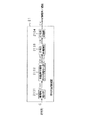
まず、音響信号符号化装置の実施の形態としては、図1に示すような構成のものを挙げることができる。
【0026】
この音響信号符号化装置1は、時系列信号Sを振幅操作情報Gによって振幅操作を行った後にスペクトルFに分解するスペクトル変換部101と、そのスペクトルFを正規化情報Nによって正規化する正規化部102と、正規化されたスペクトルFNを量子化情報Qによって量子化する量子化部103と、量子化されたスペクトルFQ、振幅操作情報G、正規化情報Nおよび量子化情報をもとに符号列Cを生成する符号列生成部104とを有している。
【0027】
スペクトル変換部101は、この符号化装置1に入力する時系列信号Sに振幅操作を施した後に周波数成分であるスペクトルFに分解する。そして、スペクトルFを正規化部102に、振幅操作情報Gを符号列生成部104に、それぞれ出力する。
【0028】
正規化部102は、スペクトル変換部101から入力するスペクトルFに正規化を施す。そして、正規化されたスペクトルFNを量子化部103に、正規化情報Nを符号列生成部104に、それぞれ出力する。
【0029】
量子化部103は、正規化部103から入力する正規化されたスペクトルFNに量子化を施す。そして、量子化されたスペクトルFQおよび量子化情報Qを符号列生成部104に出力する。
【0030】
符号列生成部104は、スペクトル変換部101からの振幅操作情報G、正規化部102からの正規化情報N、量子化部103からの量子化情報Qに基づいて、量子化部103からの量子化されたスペクトルFQを符号化して、符号列Cを出力する。
【0031】
この符号化装置1のスペクトル変換部101は、図2に示すような構成のスペクトル変換部2として具体化することができる。
【0032】
このスペクトル変換部2は、入力される時系列信号Sをブロック化してブロック化信号SBとするブロック化部201と、ブロック化信号SBに振幅操作を施して振幅操作されたブロック信号SBCとするとともに振幅操作情報Gを外部に出力する振幅処理部202と、振幅操作されたブロック化信号SBCに窓関数Wを作用させて窓関数Wを作用させたブロック化信号SBGWとする窓関数作用部203と、窓関数Wを作用させたブロック化信号SBGWにスペクトル変換を施してスペクトルFを出力するスペクトル変換手段204とを有している。
【0033】
スペクトル変換部2に入力する時系列信号Sは、ブロック化部201によってある長さの時区間にブロック化されてブロック化信号SBとされる。ブロック化信号SBは、振幅処理部202によって後述の部分に使用するために振幅操作を受けて振幅操作されたブロック化信号SBGとされる。振幅操作されたブロック化信号SBGは、周波数分解能向上のために窓関数作用部203によって適切な窓関数Wを作用させ窓関数Wを作用させたブロック化信号SBGWとされる。窓関数Wを作用させたブロック化信号SBGWは、スペクトル変換手段204によってスペクトル変換を施されてスペクトルFとなされる。
【0034】
上記符号化装置1のスペクトル変換部101は、図3に示すような構成のスペクトル変換部3としても構成することができる。
【0035】
このスペクトル変換部3は、入力される時系列信号Sをブロック化してブロック化信号SBとするブロック化部201と、ブロック化信号SBに窓関数Wを作用させて窓関数Wを作用させたブロック化信号とする窓関数作用部302と、窓関数Wを作用させたブロック化信号SBWに振幅操作を施し振幅操作されたブロック化信号SBWとするとともに外部に振幅操作情報Gを出力する振幅処理部303と、振幅操作されたブロック化信号SBGWにスペクトル変換を施してスペクトルFとするスペクトル変換手段304とを有している。
【0036】
スペクトル変換部3に入力する時系列信号Sは、ブロック化部301によってある長さの時区間にブロック化される。ブロック化部301からのブロック化信号SBは、このブロック化信号SBの前後に生成されるブロック化信号との整合性を持たせるために窓関数作用部302によって適切な窓関数Wを作用させた窓関数Wを作用させたブロック化信号WSBとなされる。この窓関数Wを作用させたブロック化信号WBSは、後述する部分に使用するため振幅処理部303によって振幅操作Gを受ける。この振幅操作されたブロック化信号SBWGをスペクトル変換手段304によってスペクトルFに変換する。
【0037】
上述した符号化装置1のスペクトル変換部を具体化した、スペクトル変換部2と、スペクトル変換部3との信号処理の違いは、窓関数Wを振幅操作前に作用させるか後に作用させるかの違いである。すなわち、前後のブロック化信号との整合性を重視するか、または振幅操作を重視するかの違いではある。したがって、適切な窓関数Wの選択によりどちらの方法を用いても後述する部分に使用することが可能である。
【0038】
スペクトル変換部3の操作は、図4に示すように具体化することができる。
【0039】
図4中の(a)に示す原信号Sを、一定の時区間のブロックBで分割しブロック化を行う。この際ブロックBは前後のブロックBと半分の領域を共有して持つ。すなわち、図4中の(b)に示す窓関数W1の時区間の後半は(c)に示す窓関数W2の時区間の前半と共通している。また、窓関数W2の時区間の後半は、図4中の(d)に示す窓関数W3の時区間の前半と共通している。そして、共有される領域の合成振幅が原信号に等しくなるような窓関数W1から窓関数W3を作用させることによって、図4中の(e)に示すブロック化信号SBW1、(f)に示すブロック化信号SBW2および(g)に示すブロック化信号SBW3を得る。これらブロック毎に振幅操作Gを行い、スペクトルFに変換を行う。今後、簡単化のためSBWをSBと表すことにする。
【0040】
続いて、ブロック化信号SBに対して振幅を操作しないでスペクトル変換を行う場合についての問題を図5以降を参照しながら説明する。
【0041】
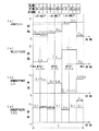
図5は、後述する音響信号の処理の前提となる技術を説明するために、特徴のあるブロック化信号である原信号SBを考え、この原信号SBについて行う波形操作についてしめすものである。
【0042】
このブロック化信号SBは周波数が1KHzと一定で、ある領域毎に振幅のみが変化する信号である。信号の振幅を検出するためには1つのブロックBを一定の小領域毎にサブブロックBsと呼ぶ小ブロック毎に分割し解析を行う。図5中の(a)に示すブロック化信号SBの振幅変化は、このサブブロックBs毎に規則的に生じているものとする。
【0043】
このブロック化信号SBをスペクトル変換することを考えると、信号の周波数は一定ではあるが、サブブロックBs毎に振幅が変化しているので、スペクトル変換によって得られるスペクトルFの分布は図5中の(b)に示すように1KHzに最大振幅をもつものの、他の周波数成分をも持つ分布になってしまい、符号化効率は悪化する。
【0044】
スペクトル成分Fを逆スペクトル変換によってブロック化信号SBに戻すことを考える。その場合は、図6中の(a)に示す振幅特性を逆スペクトル変換すれば本来の信号Sが復元されるはずではあるが、正規化/量子化の精度が十分でない符号化/復号化スペクトルに逆スペクトル変換を施した場合には図6中の(b)に示すように振幅変化の肩が鈍った復元信号SB’となる。このような信号波形の変化は聴感上の障害になることが経験上知られており、対策を必要とする。
【0045】
スペクトル変換を行う長さをブロックBからサブブロックBsに変更すると、図7中の(a)に示す原信号をスペクトル変換した理想振幅特性は(b)に示すようになる。即ち振幅が変化しないサブブロック毎にスペクトル変換を行えば、どの時間においてもスペクトルの成分は1KHzのみであるということになる。
【0046】
この場合、前後のサブブロックとの整合性が完全であれば符号化効率は飛躍的に向上し振幅変化も高精度に保存されるが、変換のブロック長を切り替える手段が必要となり符号化装置の規模が大きく複雑になってしまう。またブロック長を分割することによって、1つのサブブロックに対するビット量も分割されることになり、こと高能率に符号化を行おうとする場合には変換ブロック内でのビット配分が大きく減少するのでビット割当アルゴリズムも複雑/困難なものとなる。
【0047】
本実施の形態では、ブロックBを一定としたままでブロックB内の振幅を一定に保つ操作を行うもとする。このような振幅操作を行う振幅操作部の構成を、図8に示す。
【0048】
この振幅処理部8は、入力されたブロック化信号SBの振幅を解析して振幅操作情報GBを出力する振幅解析部801と、上記ブロック化信号SBおよび振幅情報GBに基づいて振幅操作情報SBGを出力する振幅操作部806とを有している。振幅処理部8においては、ブロック化信号SBを2分配し、その一方を振幅解析部801によって振幅を解析し、振幅操作情報を得る。
【0049】
振幅解析部801は、ブロック化信号SBをサブブロック信号SBsに分割するサブブロック分割部802と、サブブロック毎の振幅情報GBsを検出する振幅変化検出部803と、1つ前のブロックのサブブロックの振幅操作情報GBs−1を保持しておく振幅変化情報保持部804と、振幅情報GBs,GBs−1から振幅操作情報GBを生成する振幅操作情報生成部805から構成される。
【0050】
振幅解析部801に入力したブロック化信号SBは、サブブロック分割部802にてサブブロック信号SBsに分割される。サブブロック分割部802からのサブブロック信号SBsは、振幅変化検出部803で検出された振幅情報GBsは、振幅変化情報保持部804および振幅操作情報生成部805にそれぞれ出力される。振幅変化情報保持部804では、振幅変化検出部803からの振幅情報GBsを1ブロック遅延させる。振幅操作情報生成部805では、振幅変化検出部803からの振幅情報GBsおよび振幅変化情報保持部804からの1ブロック遅延された振幅情報GBs−1をもとに、振幅操作情報GBを生成する。
【0051】
振幅操作部806は、振幅操作情報生成部805からの振幅操作情報GBをもとブロック化信号SBに対して実際に振幅操作を施して、振幅操作信号SBGを出力する。
【0052】
振幅操作情報生成部805では、サブブロック毎の振幅を検出して振幅操作情報GBを作成するが、サブブロック毎に非連続に振幅操作を行うとギブス現象が発生して周波数分解能を悪化させる場合があるので、振幅操作は図9中の(a)に示すように過渡部を設けるようにする。
【0053】
また前後のブロックの整合性を計るために図9中の(a)に示すようなブロック1の振幅操作情報1とブロック2の振幅操作情報2の連結部の差分を吸収し(b)の実線で示すように振幅操作量を一致させることで前後ブロックの整合性を確保する。この場合にも振幅操作はサブブロック毎に行なわれる。サブブロック間の振幅操作情報を接続する場合には、図9中の(b)の実線で示す直線補間よりも点線で示すように滑らかな曲線によって振幅操作情報を補間したほうが、不連続性によって発生するギブス現象を少なくすることが可能である。
【0054】
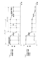
続いて、実際の振幅操作の方法について、図10に示す具体例を参照して説明する。
【0055】
図10中の(a)は図5中の(a)に示した信号と同一のものである。この信号に対して振幅操作を行うが、振幅操作は説明の簡単化のため1つのブロックBのみを対象とし、また振幅操作量はサブブロックBs毎に一定に変化するものとする。即ち図10(a)に示すように振幅変化はサブブロックBs毎に非連続的に検出を行うこととすることを注意されたい。
【0056】
図10中の(a)においては、原信号の振幅はサブブロックBs毎にGa,Gb,Gc,Gd,Ge,Gfと徐々に増加している。この振幅をブロックB内で一定に保つように、振幅操作情報を図10中の(b)に示すように振幅情報生成部によって作成する。
【0057】
作成された振幅操作情報は、ブロックB内の振幅を一定のGfに保つため、それぞれGf/Ga,Gf/Gb,Gf/Gc,Gf/Gd,Gf/Ge,Gf/Gf=1と振幅操作量が決定され、振幅操作部によって図10中の(a)に対して振幅操作を行いって(c)を得る。
【0058】
図10(c)は、振幅はGfと一定の1KHzの信号であるから、その理想振幅特性は図10(d)の実線で示すように振幅Gfの単スペクトルとなる。ただしブロックBの長さは有限であるので実際の振幅特性は図10中の(d)の点線で示すように幾分拡がった分布になるが、図5中の(b)に示した振幅特性と比較した場合には遥かに高い符号化効率を得ることが可能となる。
【0059】
図10中の(a)に示した振幅特性が理想的なスペクトル変換を行ったものであるとして、図11中の(a)に示すように単スペクトルになった場合を仮定し、この単スペクトルを逆スペクトル変換すると図11中の(b)に示すような振幅Gfが一定の信号を得る。
【0060】
この図11中の(b)に対して、スペクトル変換前に行った図10中の(b)の振幅操作と逆の振幅操作である図11中の(c)の逆振幅操作を行うと、復元信号(d)を得ることができる。この図11中の(d)に示した復元信号は、図6中の(b)に示した復元信号SB’と比較した場合、原信号である図10中の(a)により忠実なものとなる。
【0061】
このように、スペクトル変換前と逆スペクトル変換後の信号に対して振幅操作を行うことで、高能率かつ高精度に信号波形の符号化が可能となる。そして、聴感上の障害となりうるブロック内での振幅の変化を最小限に抑制することができる。
【0062】
さて今までは単周波数成分しか持たない理想的な条件の下で説明してきたが、今度は一般的な例を用いて解説する。
【0063】
図12中の(a)は、様々な周波数成分をもった信号である。この信号を符号化/復号化を行うとその信号波形は(b)のように変化してしまう現象が生じる場合がある。このような信号の振幅変化は聴感上の障害となる。
【0064】
図12において符号化前/復号化後の信号の振幅が変化してしまう原因は、原信号を幾つかの帯域に分割することで詳しく解析可能となる。図12中の(a)に示す原信号を図13中の(a)に示す低周波数成分信号及び図13中の(b)に示す高周波成分信号に分割して解析を行うと、低周波数成分信号の振幅変化と比較して高周波数成分信号の振幅変化が大きいことがわかる。
【0065】
振幅変化の少ない低周波数成分は図13中の(c)に示すように図13中の(a)に示した原信号高精度に復元されているが、振幅変化の大きい高周波数成分は図13中の(d)に示すように本来の図13中の(b)に示した原信号とは大きく変化していることがわかる。この高周波数成分の信号の変化が、復元信号の振幅変化となり聴感上の障害となる。
【0066】
即ち、原信号の振幅変化よりも帯域分割された信号毎の振幅変化が大きい場合があり、原信号の振幅を一定に操作しただけでは図10、図11に示したように、原信号を精度よく復元することはできない。
【0067】
上述のような前提の下に、以下では、本発明の実施の形態について説明する。以下で述べる実施の形態により、上述したような課題が解決される。
【0068】
本実施の形態における符号化装置においては、音響信号を複数の帯域に分割し、その音響信号のサブブロック単位で上記複数の周波数帯域に分割されたそれぞれの帯域の信号の振幅を検出し、少なくとも一つの振幅情報に基づいて上記音響信号の振幅を操作するものである。
【0069】
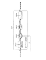
この符号化装置は、図14に示すような構成に具体化することができる。
【0070】
この符号化装置14は、入力信号を複数Mの帯域信号SD1からSDMに分割する帯域フィルタバンク部1401と、帯域フィルタバンク部1401からの帯域信号SD1からSDMについてそれぞれスペクトル変換を行いスペクトルFD1からFDMとするとともに振幅操作情報Gを生成するスペクトル変換部1402と、スペクトル変換部1402からのスペクトルFD1からFDMのそれぞれについて正規化を行い正規化スペクトルFN1からFNMとするとともに正規化情報Nを生成する正規化部1403と、正規化部1403からの正規化スペクトルFN1からFNMのそれぞれの帯域について量子化を行い量子化スペクトルFQ1からFQMとするとともに量子化情報Qを生成する量子化部1404と、スペクトル変換部1402からの振幅操作情報G、正規化部1403からの正規化情報N、および量子化部1404からの量子化情報Q、量子化部1404からの量子化スペクトルFQ1からFQMについて符号列を生成する符号生成部1403とを有している。
【0071】
この符号化装置14に入力する原信号Sは、帯域分割フィルタバンク部1401によって複数Mの帯域信号SD1からSDMに分割される。この時用いられる分割フィルタバンク1401には、前述したQMFフィルタバンクやPQFフィルタバンクなどが用いられる。帯域信号SD1からSDMは、それぞれの帯域のスペクトル変換部1402によってスペクトル変換される。このスペクトル変換部1402は、振幅操作を行う図2または図3、及び図8に示したような部分を有しており、SD1からSDMを振幅操作情報Gによって振幅操作を施してスペクトルFD1からFDMに変換を行う。
【0072】
ここで、帯域フィルタバンク部1401によって、各帯域に分割された原信号は、スペクトル変換部1402にて各帯域毎に振幅を検出される。そして、少なくとも一つの周波数帯域の振幅情報に基づいて振幅操作が施された後にスペクトル変換が施される。
【0073】
スペクトルFD1からFDMは正規化情報Nによって正規化部1403で正規化され正規化スペクトルFN1からFDMとなる。正規化スペクトルFN1からFDMは量子化情報Qによって量子化部1404で量子化され量子化スペクトルFQ1からFQMとなり、G,N、Qとともに符号列生成部1405によってそれぞれ符号CFQ1〜CFQM、CG、CN、CQに変換され、これらが多重化された符号列Cが出力される。
【0074】
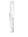
符号化装置14から出力される符号列Cは、この符号列Cの単位であるフレーム毎に、図15に示すように構成されている。すなわち、1フレーム分の符号列は、振幅操作情報CG1からCGM、正規化情報CN、量子化情報CQおよび量子化スペクトルCFQ1からCFQMの順序で配列して構成されている。
【0075】
この符号化装置は、原信号をある帯域毎に分割してその分割された信号毎に対して図10、図11に示したような振幅操作を行うことにより符号化を行うものである。この符号化装置は、帯域に分割した信号に対して上述した振幅操作を行うことにより、図12、図13に示したような符号化前/復号化後の信号の振幅変化を抑制することが可能とするものである。
【0076】
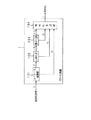
続いて、上記符号化装置14において、帯域分割数Mを2に設定した例について、図16を参照して説明する。
【0077】
図12中の(a)に示す原信号を、帯域分割フィルタ1401によって図16中の(a)に示す低周波数成分信号と(c)に示す高周波数成分信号に分割する。これら信号に対して、図10に示したような振幅操作を行ことによって図16中の(b)の振幅操作低周波数信号及び図16中の(d)の振幅操作高周波数信号へ振幅操作を行ったのちにスペクトル変換を施すことで、高能率かつ高精度に信号波形の符号化を可能とし、復元信号の振幅変化による聴感上の障害を最小限に抑制することができる。
【0078】
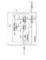
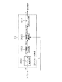
続いて、原信号を帯域分割したそれぞれの帯域の振幅情報のみを利用する符号化装置について、図17を参照して説明する。この符号化装置16は、図13に示した復元信号の振幅変化による聴感上の障害の抑制のために、帯域分割した振幅情報のみを利用するものである。
【0079】
この符号化装置16は、入力された原信号Sを複数Mの帯域信号SD1からSDMに分割する帯域分割フィルタバンク1601と、帯域信号SD1からSDMおよび原信号Sをもとに振幅解析およびスペクトル変換を行い振幅操作情報GおよびスペクトルFを生成するスペクトル変換部1602と、スペクトルFを正規化して正規化スペクトルFNとするとともに正規化情報Nを生成する正規化部1606と、正規化スペクトルFNを量子化する量子化して量子化スペクトルFQとするとともに量子化情報Qを生成する量子化部1607と、振幅操作信号G、正規化情報Nおよび量子化情報Q、量子化スペクトルFQに基づいて符号列Cを生成する符号生成部1608とを有している。
【0080】
上記スペクトル変換部1602は、帯域分割フィルタバンク1601からの帯域信号SD1からSDMをそれぞれ振幅解析して振幅解析情報GBおよび振幅操作情報Gを生成する振幅解析部1603と、原信号Sおよび振幅解析情報GBに基づいて振幅操作を行い振幅操作された信号SBCを出力する振幅操作部1604と、振幅操作された信号SBCにスペクトル変換を施してスペクトルFを出力するスペクトル変換手段1605とを有している。
【0081】
まず入力信号である原信号Sは2分配され、一方の信号を帯域分割フィルタバンク部1601によって複数の帯域信号SD1からSDMに分割し、それぞれの帯域信号毎に振幅解析部1603によって振幅情報を解析し振幅操作情報GBを得る。振幅操作部1604では、振幅操作情報GBによって原信号Sを振幅操作部1604によって振幅を操作を行って振幅操作された信号SBGとし、スペクトル変換手段1605によってスペクトルFに変換が施される。
【0082】
スペクトルFは、正規化情報Nによって正規化部1606で正規化され正規化スペクトルFNとなる。正規化スペクトルFNは量子化情報Qによって量子化部1607で量子化され量子化スペクトルFQとなり、G、N、Qとともに符号列生成部1608によって符号CFQ,CG,CN,CQに変換され、これらが多重化されて符号列Cとして出力される。
【0083】
符号化装置16から出力される符号列Cは、この符号列Cの単位であるフレーム毎に、図18に示すように構成されている。すなわち、1フレーム分の符号列は、振幅操作情報CG、正規化情報CN、量子化情報CQおよび量子化スペクトルCFQの順序で配列して構成されている。
【0084】
続いて、上記符号化装置16において、帯域分割数Mを2に設定した例について、図19を参照して説明する。
【0085】
図19中の(a)に示す原信号は、帯域分割フィルタ1601によって図17中の(b)の低周波数成分信号と(c)の高周波数成分信号に分割される。符号化装置16は、これらの信号を解析し、振幅変化量が大きい帯域の振幅情報のみを使用して原信号に対して振幅操作を行うので、図19中の(d)の振幅操作信号は振幅が一定になっていないため、高能率かつ高精度に信号波形の符号化を可能とすることは保証できないが、振幅変化の大きい高周波数成分の復元信号の振幅変化による聴感上の障害を抑制することは可能である。
【0086】
ブロック内をサブブロックに分割し振幅操作を行うことが音質上有効であることを示してきたが、サブブロック毎の振幅情報をすべて符号化して記録することは情報量の増加を意味し、高能率符号化と相反するものである。このため、振幅情報の制限を行い、振幅操作にかかる情報の削減を行う手法について説明する。
【0087】
実査にゲインコントロールを行う変化点を設定し、変化点から次の変化点を一つの領域として、各領域毎に最大振幅値がGfになるようにゲインコントロールを行う。
【0088】
図20中の(a)は原信号SBの振幅情報を示したものである。先頭のサブブロックから振幅量を検出し、変化量及び変化量の順序が示されている。ここで聴感上の障害がなるべく発生しないように振幅変化量が少ない順に制限を行うことで振幅操作情報の増加を抑制する。
【0089】
図20中の(b)は振幅操作を行うサブブロックを変化量の大きい順から3つに限定したものである。ここでは図に示したように実際にゲインコントロールを行う変化点を設定し、変化点から次の変化点までを一つの領域として、各領域毎に最大振幅値がGfになるようにゲインコントロールを行う例を示す。
【0090】
図20中の(c)は図20中の(b)から導出した振幅操作情報GBであり、この振幅操作情報GBを原信号SBに対して操作させたものが図20中の(d)の振幅操作信号SBGとなる。
【0091】
図20中の(d)の振幅はブロック内で一定ではないが、振幅変化の大きいサブブロックに関して振幅操作を行い、振幅変化の少ないサブブロックの情報を削減しており、符号化/復号化による信号波形上の振幅変化が大きく現れやすい部分に関して確実に操作を行うことで、復号化信号に現れる聴感上の障害を抑制することが可能である。
【0092】
図21も振幅操作にかかる情報量の削減を行う手法を示したものである。
【0093】
図21中の(a)には原信号SBの振幅情報を示したものである。先頭のサブブロックから振幅量を検出し、変化量及び変化量の順序が示されている。ここで聴感上の障害がなるべく発生しないように振幅変化量がある一定のしきい値より少ない場合に制限を行うことで振幅操作情報の増加を抑制する。
【0094】
図21中の(b)は振幅操作を行うサブブロック間の振幅変化量がしきい値以下の場合、隣接するサブブロックと合成することで振幅情報を削減している。ここでは、各変化点において検出された変化量がしきい値以下の場合、その変化点に隣接するサブブロックの振幅が大きい方の最大振幅値がGfになるように振幅操作を行う例である。
【0095】
図21中の(c)は、図21中の(b)から導出した振幅操作情報GBであり、この振幅操作情報GBを原信号SBに対して操作させたものが図21中の(d)の振幅操作信号SBGとなる。
【0096】
図21中の(d)の振幅はブロック内で一定ではないが、振幅変化の大きいサブブロックに関して振幅操作を行い、振幅変化の少ないサブブロックの情報を削減しており、符号化/復号化による信号波形上の振幅変化が大きく現れやすい部分に関して確実に操作を行うことで、復号化信号に現れる聴感上の障害を抑制することが可能である。
【0097】
次に、逆正規化されたスペクトルを時系列信号に合成するための逆スペクトル変換部について説明する。
【0098】
逆スペクトル変換部29は、図22に示すような構成に具体化される。この逆スペクトル変換部29は、入力されたスペクトルFに逆スペクトル変換を施して復元ブロック信号SBとする逆スペクトル変換手段2901と、復元ブロック信号SBおよび外部から入力された振幅操作情報Gに基づいて逆振幅操作を施してSB/Gとする逆振幅操作部2902と、SB/Gに窓関数Wを作用させてSBW/Gとする窓関数作用部2903と、SBW/Gに逆ブロック化を施して時系列信号S’とする逆ブロック化部2904とから構成されている。
【0099】
この逆スペクトル変換部29においては、まず復号化されたスペクトルFを逆スペクトル変換手段2901によって逆スペクトル変換を施し復元ブロック化信号SBを得る。この復元ブロック化信号SBに対し符号化装置によって行われた振幅操作Gと逆の振幅操作を逆振幅操作部2902によって施す。逆振幅操作が施された復元ブロック化信号SBは、前後のブロックとの整合性を保つために窓関数作用部2903によって窓関数Wを作用させ、逆ブロック化部2904によって前後のブロックとの合成が行われれ、復元された時系列信号S’を得る。
【0100】
逆スペクトル変換部は、図23に示すような構成としても具体化される。
【0101】
この逆スペクトル変換部30は、入力されたスペクトルFに逆スペクトル変換を施して復元ブロック信号SBとする逆スペクトル変換手段3001と、復元ブロック化信号SBに窓関数Wを作用させてSBWとする窓関数作用部3002と、SBWおよび外部から入力された振幅操作情報Gに基づいて逆振幅操作を施してSBW/Gとする逆振幅操作部3003と、SBW/Gに逆ブロック化を施して時系列信号S’とする逆ブロック化部3004とを有している。
【0102】
この逆スペクトル変換部30においては、まず復号化されたスペクトルFを逆スペクトル変換手段3001によって逆スペクトル変換を施し復元ブロック化信号SBを得る。この復元ブロック化信号SBに前後のブロックとの整合性を保つために窓関数作用部3002によって窓関数を作用させ、さらに符号化装置によって行われた振幅操作Gと逆の振幅操作を逆振幅操作部3003によって施す。逆振幅操作が施された復元ブロック化信号SBは、逆ブロック化部3004によって前後のブロックとの合成が行われ、復元信号S’を得る。
【0103】
続いて、図22に示した逆ブロック化部29における操作は、図24に示すように具体化することができる。
【0104】
図24において、図中の(a)に示す各ブロック毎に逆スペクトル変換された復元ブロック化信号SB/G1、図中の(b)に示す復元ブロック化信号SB/G2、および図中の(c)に示す復元ブロック化信号SB/G3(c)は、前後のブロックと半分の領域を共有して持ち、共有される領域の合成振幅が原信号に等しくなるように、図中の(d)に示す窓関数W1、図中の(e)に示す窓関数W2、および図中の(f)に示す窓関数W3(f)を作用させることによって、図中の(g)に示す復元信号S’を得る。
【0105】
図24に示した逆スペクトル変換部29の逆振幅操作部2902は、図25の逆振幅操作部32に示すように具体化することができる。
【0106】
この逆振幅操作部32は、入力された振幅操作情報Gから振幅を復元する振幅復元部3201と、入力された振幅操作信号SBおよび振幅復元部3201からの逆振幅操作情報1/GBをもとに復元ブロック化信号SB/Gを生成する逆振幅操作部3204とを有している。
【0107】
振幅復元部3201は、振幅操作情報Gを保持して1ブロック遅延させる振幅操作情報保持部3202と、振幅操作情報保持部3202からの遅延された振幅操作情報および振幅操作情報Gに基づいて逆振幅操作情報を生成する逆振幅操作情報生成部3203とを有している。
【0108】
この逆振幅操作部32においては、まず振幅操作情報Gを用いて振幅復元部3201によって、符号化装置で行った振幅操作と逆の振幅操作情報1/GBを生成し、復元ブロック化信号SBに対して逆振幅操作部3204によって振幅操作を行い、復元ブロック化信号SB/Gを得る。
【0109】
振幅復元部3201の内部では、前のブロックの振幅操作情報を保持しておく振幅変化情報保持部3202からの振幅情報G−1及び現在のブロックの振幅情報Gから逆振幅操作情報生成部3203によっによって逆振幅操作情報1/GBを生成する。
【0110】
逆振幅情報生成部3204では、図26に示すようにサブブロック毎の振幅を復元して振幅操作を行う逆振幅操作情報1/GBを作成する。符号化装置においてサブブロック間の振幅操作量を曲線によって補間されている場合には、逆振幅操作信号の振幅を正確に復元するため復号化装置においても曲線補間する必要がある。
【0111】
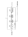
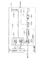
符号化装置において帯域分割フィルタを用いて帯域毎信号に分割し、帯域毎に振幅操作を行って符号化された符号列に対する復号化装置は図27に示すように具体化される。
【0112】
この復号化装置34は、入力された符号列Cを複数Mの量子化スペクトルFQ1からFQMに分解する符号分解部3401と、符号分解部3401からの量子化スペクトルFQ1からFQMに逆量子化を施して正規化スペクトルFN1からFNMとする逆量子化部3402と、逆量子化部3402からの正規化スペクトルFN1からFNMに逆正規化を施してスペクトルFD1からFDMとする逆正規化部3493と、逆正規化部3403からのスペクトルFN1からFNMに逆スペクトル変換を施して復元信号SD1からSDMとする逆スペクトル変換部3404と、復元信号SD1からSDMを帯域合成して時系列信号SD’とする帯域合成フィルタバンク部3405とを有している。
【0113】
この符号化復号化装置においては、符号列Cは符号列分解部3401によって帯域毎に量子化スペクトルFQ1からFQMに分解されるとともに、符号列Cから量子化情報Q、正規化情報Nおよび振幅操作情報Nが抽出される。
【0114】
符号分解部3401による分解により得られたFQ1からFQMまでの量子化スペクトルは、量子化情報Qを用いて逆量子化部3402によって正規化スペクトルFN1からFNMに逆量子化され、正規化情報Nを用いて逆正規化部3403によってスペクトルFD1からFDMに逆正規化され、逆スペクトル変換部3404によって帯域毎の復元信号SD1からSDMに合成される。帯域毎の復元信号SD1からSDMは帯域合成フィルタバンク部3405によってすべての帯域信号を含む復元信号S’に復元される。
【0115】
逆スペクトル変換部は図22に示した逆スペクトル変換部29、図23に示した逆スペクトル変換部30のように構成され、逆振幅操作はGをもとに行われる。
【0116】
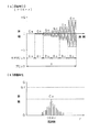
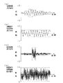
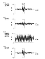
図28は振幅操作を行わずに符号化/復号化を行った場合と振幅操作を行い符号化/復号化を行った場合の結果を比較したものである。
【0117】
図28中の(a)に示す波形は、図12中の(a)に示した原信号の波形の高周波数成分信号であり、これを振幅操作しないで符号化/復号化した場合には復元信号は図28中の(b)に示す波形のようになり、原信号に比較して復元信号の振幅が大きく変化しており聴感上障害が発生する。
【0118】
一方、図28中の(c)に示す波形は図28中の(a)示す波形に対して、図10に示したように符号化装置においてブロック内の振幅が一定になるように振幅操作を行った信号である。この図28中の(c)示す波形を符号化し復号化時に逆の振幅操作を行うことで図28中の(a)に示す波形に忠実な振幅を持つ図28中の(d)に示す波形の復元信号を得ることができる。
【0119】
符号化装置において帯域分割フィルタを用いて帯域毎信号に分割し、各帯域の振幅情報のみを利用して符号化された符号列に対する復号化装置36は図29に示すように具体化される。
【0120】
この復号化装置36は、入力された符号列Cを、量子化スペクトルFQ、量子化情報Q、正規化情報N、および振幅操作情報Gに分解する符号分解部3601と、符号列分解部3601からの量子化スペクトルFQおよび量子化情報Qに基づいて正規化スペクトルFNを生成する逆量子化部3602と、逆量子化部3602からの正規化スペクトルFNおよび符号分解部3601からの正規化情報に基づいてスペクトルFを復元する逆正規化部3603と、逆正規化部3603からのスペクトルFからのスペクトルFおよび符号分解部3601からの振幅操作情報Gに基づいて逆スペクトル変換を施して時系列信号G’を復元する逆スペクトル変換部3606とを有している。
【0121】
この符号化装置36においては、帯域毎の振幅情報を得るために帯域分割フィルタを必要としたが、復号化装置では帯域分割されていない信号の逆振幅操作のみを行えば良いので、図27に示した符号化復号化装置34のような帯域合成フィルタ3405は必要としないため、後述する図34に示す基本的な復号化装置24と同じ構成となり、構造が簡単になるという利点がある。
【0122】
図30は振幅操作を行わずに符号化/復号化を行った場合と振幅操作を行い符号化/復号化を行った結果を比較したものである。図30中の(a)に示す波形は図12に示した高周波数成分信号であり、これを振幅操作しないで符号化/復号化した場合には復元信号は図30中の(b)に示す波形のようになり、原信号に比較して復元信号の振幅が大きく変化しており聴感上障害が発生する。
【0123】
一方、図30中の(c)に示す波形は図30中の(a)に示した原信号の波形に対して、図17に示したように符号化装置において高周波数成分の信号がブロック内の振幅が一定になるように振幅操作を行った信号である。この図30中の(c)に示す波形を符号化し復号化時に逆の振幅操作を行うことで図30中の(c)に示す波形に忠実な振幅を持つ図30中の(c)に示す復元信号を得ることができる。
【0124】
次に、上述のように振幅操作が施された後に符号化された符号化データを復号化する復号化装置について説明する。
【0125】
まず、符号化装置によって生成された符号列Cを、記録媒体に記録、または通信によって伝送を行うような符号列記録装置について説明する。
【0126】
この符号列記録装置21は、図31に示すように、入力される符号列Cに暗号化を施すための鍵情報Kを選択する鍵情報選択部2101と、鍵情報Kによって振幅操作情報符号列CGに足対して暗号化を施す振幅操作情報符号列暗号化部2102と、暗号化された振幅情報暗号化符号列CKとそれ以外の符号列C−CGを一つの符号列に再構築した符号列CRを出力する符号列再構築部2103と、符号列再構築部2103にて再構築された符号列CRを実際に記録する符号列記録部2104を有してなる。
【0127】
図31に示した符号列記録装置21の振幅操作情報符号列暗号化部2102は、図32に示すように具体化することができる。
【0128】
この振幅操作情報符号列暗号化部22は、入力された符号列Cから振幅操作情報符号列CGの抽出を行うとともに振幅操作情報以外の符号列C−CGを出力する振幅操作情報符号列の抽出部2201と、振幅操作情報符号列の抽出部2201からの振幅操作情報符号列CGおよび入力された鍵情報Kに基づいて符号列を暗号化して振幅操作情報暗号化符号列を出力する符号列暗号化部2202とを有している。
【0129】
この振幅操作情報符号列暗号化部22においては、符号列Cから振幅情操作情報のみを振幅操作情報符号列抽出部2201によって抽出した振幅操作情報符号列CGに対し鍵情報Kを用いて符号列暗号化部2202によって暗号化を行う。振幅操作情報符号列暗号化部22は鍵情報K、振幅情報暗号化符号列CKおよび振幅情報以外の符号列C−CGを出力する。
【0130】
符号列記録装置21によって記録/伝送される符号列CRでは、図33に示すように、振幅操作情報に関する符号列がフレーム毎の符号列の先頭部に記録される。このように記録することで、復号化装置においては符号列の先頭を検査しただけで、その符号列が暗号化されてるかいないかを判定可能となる。無論、符号列の先頭以外に記録しても一向に問題はない。
【0131】
符号列記録装置によって記録/伝送された符号列CRを復元する復号化装置は、図34に示すように、記録/伝送されてきた符号列CRを復号化装置に取り込むために符号列読出部2401、符号列Cを分解する符号列分解部2402、分解された符号列Qを基に逆量子化を行う逆量子化部2403、逆量子化されたスペクトルFQに対して逆正規化を行う逆正規化2404、及び逆正規化されたスペクトルFを復元信号S’に合成する逆スペクトル変換部2405を有してなる。
【0132】
符号列読み出し部2401は、記録媒体または通信回線からの符号列CRおよび鍵情報Kに基づいて符号列の読み出しを行い、符号列Cを出力する。
【0133】
符号列分解部2402は、符号列Cを分解して量子化スペクトルFQ、量子化情報Q、正規化情報および振幅操作情報Gを得る。
【0134】
逆量子化部2403は、量子化スペクトルFQおよび量子化情報Qをもとに逆量子化を行い、正規化スペクトルFNを出力する。
【0135】
逆量子化部2404は、正規化スペクトルFNおよび正規化情報Nをもとに逆正規化を行い、スペクトルFを出力する。
【0136】
逆スペクトル変換部2405は、スペクトルFおよび振幅操作情報Gをもとに、逆スペクトル変換を行い、時系列信号S’を出力する。
【0137】
図34に示した復号化装置24の符号列読出部2401は、図35の符号列読出部25に示すように具体化することができる。
【0138】
この符号列読出部25においては、符号列CRに暗号化され記録されている振幅操作情報暗号化符号列CKを解読し振幅操作情報CGを得る振幅操作情報符号列解読部2501と、符号列Cを再構築する符号列再構築部2502によって構成される。
【0139】
記録媒体/通信から入力される符号列CRは、振幅操作情報符号列解読部2501にて、別途入手される鍵情報Kにより、振幅操作情報CGに解読される。そして、符号列再構築部2502により符号列Cに再構築される。
【0140】
図35に示した符号列読出部25に備えられる振幅操作情報符号列解読部2501は、図36に示す振幅操作情報符号列解読部26にに示すように具体化することができる。
【0141】
この振幅操作符号列解読部26は、入力される符号列を分割し、暗号化符号列CKおよび振幅操作情報以外の符号列CR−CGを出力する符号列分割部2602と、別途入手された鍵情報Kを検査し、偽の場合には振幅操作情報なし、すなわちCG=0を出力し、真の場合には符号列解読部に入力する鍵情報検査部2601と、符号列分割部2602からの暗号化符号列CKおよび鍵情報検査部2601からの情報を入力され、振幅操作情報符号列CGを出力する符号列解読部2603とを有している。
【0142】
この振幅操作符号列解読部26においては、まず符号列CRを符号列分割部2602によって暗号化されている振幅操作情報暗号化符号列CK及びその他符号列CR−CGに分割する。暗号化されている振幅操作情報暗号化符号列CKを符号列解読部2603によって解読するには、暗号化に用いたものと同じ鍵情報Kを必要とする。鍵情報を入手するためには符号列の著作者に対し、許可を受けることによって鍵情報Kを入手するものとする。
【0143】
入手した鍵情報Kを鍵情報検査部2601よって検査し、暗号化された鍵情報Kに等しい場合は符号列解読部2603によって解読を行い振幅操作情報符号列CGを得ることが可能であるが、鍵情報Kが一致しない場合には振幅操作情報は0として出力される。このため、復号化装置では正しい復号化を行うことができなくなり、本来の信号に比較して振幅が大きく異なる信号となってしまう。
【0144】
符号列CRには、予め解読に必要な初期鍵情報KIを図37に示すように埋め込むことも可能である。すなわち、図37に示す符号列CRにおいては、先頭の振幅操作情報暗号化符号列に、初期鍵情報KIが続いている。
【0145】
また図38に示すように復号化装置では鍵情報がない場合でも、ある一定期間Dは鍵情報を必要としないでも暗号化された符号列の解読を可能とし、ある一定期間D後には解読が不可能になるように記録装置及び復号化装置を構成することも可能である。この機能を初期鍵情報KIにも適用することが可能であり、一定期間D後には初期鍵情報KIを使用不可とすることで、正しい復号化をできなくすることも可能である。
【0146】
即ち、ある一定期間Dのみ無償で記録された音楽などを聞くことが可能であるが、一定期間D後は使用料を支払わなければ正しい復号化が行えずに悪い音質の音楽しか聞くことができなくなる。
【0147】
このように振幅操作情報のみをを暗号化することで、符号列が何の音楽を記録しているかはわかるが、実際に音楽としては楽しむことができないようにすることで、著作権保護や課金システムとして利用可能である。
【0148】
次に、本発明に係る記録媒体の実施の形態について説明する。
【0149】
この記録媒体としては、時系列信号を複数の周波数帯域に分割する周波数帯域分割処理と、上記時系列信号の符号化の区間長であるブロック長を複数に分割したサブブロック長単位で、上記複数の周波数帯域に分割されたそれぞれの帯域の時系列信号の振幅を検出する振幅検出処理と、上記振幅検出工程で検出された少なくとも一つの周波数帯域の振幅情報に基づいて、上記時系列信号の振幅を操作する振幅操作処理と、上記振幅操作処理において振幅を操作された時系列信号を周波数成分に分解する周波数成分変換処理と、上記周波数成分変換処理からの周波数成分に正規化/量子化を施す正規化/量子化処理との各処理を有する、時系列信号を符号化する音響信号符号化のプログラムが記録されてなる記録媒体を挙げることができる。
【0150】
また、この記録媒体としては、符号列を分解する分解処理と、上記分解処理からの信号に逆量子化/逆正規化を施して周波数成分とする逆量子化/逆正規化処理と、上記逆量子化/逆正規化処理からの周波数成分を時系列信号に合成する合成処理と、上記合成処理で合成された時系列信号の符号化の区間長であるブロック長を複数に分割したサブブロック長について、この時系列信号の振幅を操作する振幅操作処理との各処理を有する、時系列信号の符号化の区間長であるブロック長を複数に分割したサブブロック長について、周波数帯域に分割された上記時系列信号の各帯域毎の振幅情報に基づいて、この時系列信号の振幅を操作した後、この時系列信号を周波数成分に分解して各周波数成分について符号化/量子化を施して符号化してなる符号列が入力し、この符号列を復号する復号化方法のプログラムが記録されてなる記録媒体を挙げることができる。
【0151】
そして、この記録媒体としては、時系列信号を複数の周波数帯域に分割する周波数帯域分割工程と、上記時系列信号の符号化の区間長であるブロック長を複数に分割したサブブロック単位で、上記複数の周波数帯域に分割されたそれぞれの帯域の時系列信号の振幅を検出する振幅検出工程と、上記振幅検出処理にて検出された少なくとも一つの周波数帯域の振幅情報に基づいて、上記時系列信号の振幅を操作する振幅操作工程と、上記振幅操作工程において振幅を操作された時系列信号を周波数成分に分解する周波数成分変換工程と、上記周波数成分変換工程からの周波数成分に正規化/量子化を施す正規化/量子化工程とを有し、時系列信号を符号化する音響信号符号化方法において上記時系列信号が符号化された符号列が記録されてなる記録媒体を挙げることができる。
【0152】
このような記録媒体は、例えば、いわゆるCD−ROM等のディスク媒体として提供される。また、この記録媒体は、例えばマルチメディア通信回線としても提供される。
【0153】
以上説明したように、本発明では、スペクトル変換を施す場合に、変換フレーム内に局所的に発生する特定の周波数成分の時系列信号の拡散を抑制するために、入力信号を複数の帯域に分割して解析を行って、信号の振幅を操作することによって信号の拡散を効果的に抑制するものである。
【0154】
【発明の効果】
上述のように、本発明においてはブロック内の振幅操作を行うことで、符号化効率が高くかつ高精度な符号化を可能とした。特に本発明では原信号を帯域毎に分割することで最適な振幅操作を行うことで、より符号化効率及び符号化精度の向上が可能となった。
【図面の簡単な説明】
【図1】符号化装置の構成を示すブロック図である。
【図2】スペクトル変換部の構成を示すブロック図である。
【図3】スペクトル変換部の構成を示すブロック図である。
【図4】スペクトル変換部における操作を示す図である。
【図5】ブロック化信号に対して振幅を操作しないで変換する場合についての問題を説明する図である。
【図6】スペクトル成分を逆スペクトル変換によってブロック化信号に戻すことを説明する図である。
【図7】スペクトル変換を行う長さをブロックからサブブロックに変更することを説明する図である。
【図8】振幅操作部の構成を示すブロック図である。
【図9】振幅操作に過渡期を設けることを説明する図である。
【図10】実際の振幅操作を説明する具体例である。
【図11】単スペクトルである場合の具体例を説明する図である。
【図12】複数の周波数成分を含む場合の具体例を説明する図である。
【図13】原信号を帯域に分割することによる解析を説明する図である。
【図14】符号化装置の構成を示すブロック図である。
【図15】フレームのデータ構成を示す図である。
【図16】原信号を帯域分割してそれぞれの帯域の振幅情報のみを利用する方法を説明する図である。
【図17】符号化装置の構成を示す図である。
【図18】フレームのデータ構成を示す図である。
【図19】符号化装置において帯域分割数を2とした場合を説明する図である。
【図20】振幅操作にかかる情報量の削減を行う手法を示す図である。
【図21】振幅操作にかかる情報量の削減を行う手法を示す図である。
【図22】逆スペクトル変換部の構成を示すブロック図である。
【図23】逆スペクトル変換部の構成を示すブロック図である。
【図24】逆ブロック化部における操作を説明する図である。
【図25】逆振幅操作部における構成を示すブロック図である。
【図26】サブブロック毎の振幅を復元して行う振幅操作を説明する図である。
【図27】符号化復号化装置の構成を示すブロック図である。
【図28】振幅操作を行わずに符号化/復号化を行った場合と、帯域別に振幅操作を行って符号化/復号化を行った場合の結果を比較する図である。
【図29】復号化装置の構成を示すブロック図である。
【図30】振幅操作を行わずに符号化/復号化を行った場合と、帯域別に振幅操作を行って符号化/復号化を行った場合の結果を比較する図である。
【図31】符号列記録装置の構成を示すブロック図である。
【図32】振幅操作情報符号列暗号化部の構成を示すブロック図である。
【図33】符号列のデータ構成を示す図である。
【図34】復号化装置の構成を示すブロック図である。
【図35】符号列読出部の構成を示すブロック図である。
【図36】振幅操作情報符号列解読部の構成を示すブロック図である。
【図37】符号列に含まれる初期鍵情報を説明する図である。
【図38】初期化鍵情報の有効期限を説明する図である。
【符号の説明】
1 符号化装置、24 復号化装置、34 符号化復号化装置、101 スペクトル変換部、102 正規化部、103 量子化部、104 符号列生成部、C 符号列、F スペクトル、G 振幅操作情報、N 正規化情報、Q 量子化情報、S 時系列信号[0001]
BACKGROUND OF THE INVENTION
The present invention relates to an acoustic signal encoding and / or decoding method and apparatus for encoding and / or decoding an acoustic signal, an acoustic signal encoding method and apparatus for decoding an acoustic signal, and programs and signals for these. The present invention relates to a recorded recording medium.
[0002]
[Prior art]
There are various techniques for high-efficiency encoding of signals such as audio or voice. For example, non-blocking frequency band that divides and encodes audio signals on the time axis into multiple frequency bands without blocking them Sub-band coding (SBC), which is a division method, and time-domain signals are converted to signals on the frequency axis (spectral conversion) and divided into multiple frequency bands, and each band is encoded. Blocked frequency band division methods, so-called transform coding, and the like can be mentioned. In addition, a high-efficiency coding method combining the above-described band division coding and transform coding is also considered. In this case, for example, after performing band division by the above band division coding, The signal for each band is spectrally converted into a signal on the frequency axis, and encoding is performed for each spectrum-converted band. For example, a quadrature mirror filter (QMF) is used as a filter for performing the frequency band division described above, and “Digital coding of speech in subbands”, RECrochiere, Bell Syst.Tech. J. Vol.55. , No.8 1976. In addition, “Polyphase Quadrature filters -A new subband coding technique”, Joseph H. Rothweiler, ICASSP 83, BOSTON, describes an equal-bandwidth filter division technique called polyphase quadrature filter (PQF). Yes.
[0003]
Here, as the above-described spectral transformation, for example, the input audio signal is blocked in a frame of a predetermined unit time, and discrete Fourier transform (DFT), discrete cosine transformation (DCT) is performed for each block. There is a spectral transformation that transforms the time axis into the frequency axis by performing modified discrete cosine transformation (MDCT) or the like. MDCT is described in “Subband / Transform Coding Using Filter Bank Designs Based on Time Domain Aliasing Cancellation”, JPPrincen & ABBradley, ICASSP 1987, Univ. Of Surrey Royal Melbourne Inst. Of Tech.
[0004]
By quantizing the signal divided for each band by the filter and spectrum conversion in this way, it is possible to control the band where the quantization noise occurs, and using the properties such as the masking effect, it is more efficient auditory. Encoding can be performed. If the normalization is performed for each band, for example, with the maximum absolute value of the signal component in that band before quantization, higher-efficiency encoding can be performed.
[0005]
As a frequency division width for quantizing each frequency component obtained by frequency band division, for example, band division considering human auditory characteristics is performed. In other words, the audio signal may be divided into a plurality of bands such as 32 bands, for example, in such a band that the bandwidth becomes wider as the high band is generally called a critical band. In addition, when encoding data for each band at this time, encoding is performed by predetermined bit allocation for each band or adaptive bit allocation, that is, bit allocation for each band. For example, when the coefficient data obtained by the MDCT processing is encoded by the bit allocation, adaptive allocation bits are assigned to the MDCT coefficient data for each band obtained by the MDCT processing for each block. Encoding is performed with numbers. The following two methods are known as bit allocation methods.
[0006]
According to IEEE Transactions of Accoustics, Speech, and Signal Processing, vol. ASSP-25, No. 4, August 1977, bit allocation is performed based on the signal size for each band. In this method, the quantization noise spectrum is flattened and the noise energy is minimized. However, since the masking effect is not utilized in the sense of hearing, the actual noise feeling is not optimal. MAKransner, “The critical band coder--digital encoding of the perceptual requirements of the auditory system”, ICASSP 1980, MIT uses auditory masking to obtain the required signal-to-noise ratio for each band. A technique for performing fixed bit allocation is described. However, in this method, even when the characteristic is measured with a sine wave input, the characteristic value is not so good because the bit allocation is fixed. In order to solve these problems, all the bits that can be used for bit allocation depend on the fixed bit allocation pattern predetermined for each small block and the signal size of each block, and the spectrum of the signal is There has been proposed a high-efficiency coding in which the division ratio into the fixed bit allocation patterns increases as the smoothness increases.
[0007]
According to this method, when energy is concentrated on a specific spectrum, such as a sine wave input, the overall signal-to-noise characteristics can be significantly improved by assigning many bits to a block including that spectrum. it can. In general, human hearing is very sensitive to signals with steep spectral components, so using this method to improve signal-to-noise characteristics simply improves the numerical value of the measurement. Rather, it is effective in improving sound quality in terms of hearing.
[0008]
Many other bit allocation methods have been proposed, and the auditory model has been further refined, and if the coding device's ability is improved, more efficient coding can be achieved by hearing. .
[0009]
In this way, if a method is used in which a signal is once decomposed into frequency components and the frequency components are quantized and encoded, quantization noise is also generated in the waveform signal obtained by decoding and synthesizing the frequency components. However, if the original signal component changes abruptly, the quantization noise on the waveform signal becomes large even if the original signal waveform is not large, and this quantization called pre / post echo Since noise is not concealed by simultaneous masking, it becomes an obstacle to hearing. In particular, when the spectral transformation is used to decompose the signal into a large number of frequency components, the time resolution is deteriorated and a large quantization noise is generated over a long period. Here, if the conversion length of the spectral conversion is shortened, the generation period of the above-described quantization noise is also shortened. However, in this case, the frequency resolution is degraded, and the coding efficiency in the quasi-stationary part is degraded. As a means for solving such a problem, a method of shortening the transform length at the expense of the frequency resolution of the signal has been proposed. However, reducing the transform length reduces the number of bits for one transform block. In some cases, sufficient quantization accuracy cannot be obtained, which may be a major obstacle in sound quality.
[0010]
As a countermeasure, in order to decode / encode an acoustic time-series signal that can suppress pre / post-echo while keeping the conversion frame length fixed, the encoding apparatus uses an acoustic time-series signal within the block. The transform block length remains fixed even when it changes greatly over time, and the signal is manipulated to increase the amplitude in the minute amplitude region, then converted / quantized to the frequency spectrum, and the manipulated amplitude information In addition, a method of recording in a coded sequence has been proposed.
[0011]
In the decoding apparatus, the inverse operation of the encoding apparatus is performed, and the amplitude information operation opposite to that of the encoding apparatus is performed on the acoustic time-series signal restored from the frequency spectrum by the amplitude information recorded in the encoded sequence.
[0012]
By the above operation, it is possible to effectively suppress the pre / post echo generated in the minute amplitude region when the acoustic time-series signal greatly changes in the block. In the amplitude information operation, the acoustic time-series signal is band-divided using a band division filter, and the amplitude information operation is performed for each band, so that the pre / post echo can be effectively suppressed more effectively. It has also been shown to be possible.
[0013]
[Problems to be solved by the invention]
However, pre- / post-echo was not the only obstacle to hearing. A particular problem arises when the frame length is set to be particularly long in the transform coding method. The longer the block length, the higher the frequency resolution and the higher the coding efficiency, but the original acoustic time-series signal is decoded as a time-series signal of a specific frequency component generated at a certain local time. In some cases, the acoustic time-series signal is diffused in the block, resulting in an audible disturbance. This phenomenon may occur even when the original acoustic time-series signal does not change greatly in the block, and this is not a problem that can be solved by a conventional apparatus for suppressing pre / post echo.
[0014]
The present invention has been made in view of the above circumstances, and it is an auditory sense that a time-series signal of a specific frequency component generated in local time is diffused in a decoded acoustic time-series signal. It is an object of the present invention to provide an acoustic signal encoding method and apparatus, an acoustic signal decoding method and apparatus, and a recording medium that suppress a failure.
[0015]
[Means for Solving the Problems]
In order to solve the above-described problem, an acoustic signal encoding method according to the present invention encodes a time-series signal, and a frequency band dividing step of dividing the time-series signal into a plurality of frequency bands; An amplitude detection step of detecting the amplitude of each time-series signal divided into the plurality of frequency bands in units of sub-block lengths obtained by dividing the block length, which is a section length of the time-series signal encoding, into a plurality of sub-block lengths; An amplitude operation step for manipulating the amplitude of the time-series signal based on amplitude operation information obtained by analyzing amplitudes of a plurality of frequency bands detected in the amplitude detection step; and an amplitude in the amplitude operation step A frequency component converting step for converting the time-series signal operated to frequency components, and a normalizing / quantizing step for normalizing / quantizing the frequency components from the frequency component converting step. In the amplitude operation step, the number of amplitude operations is limited, the amplitude operation amount is limited from the smallest, and when the amplitude operation amount is smaller than a predetermined value, the amplitude operation step is combined with the adjacent amplitude operation information. Limit the number of operations Is.
[0016]
An acoustic signal encoding apparatus according to the present invention encodes a time-series signal, and includes a frequency band dividing unit that divides the time-series signal into a plurality of frequency bands, and a section for encoding the time-series signal. Amplitude detection means for detecting the amplitude of each time-series signal divided into the plurality of frequency bands in units of sub-block lengths obtained by dividing the block length, which is a long block, and detected by the amplitude detection means Based on the amplitude operation information obtained by analyzing the amplitudes of a plurality of frequency bands, the amplitude operation means for operating the amplitude of the time series signal, and the time series signal whose amplitude has been operated by the amplitude operation means as a frequency A frequency component converting means for converting into a component, and a normalizing / quantizing means for normalizing / quantizing the frequency component from the frequency component converting means. Then, the amplitude operation means limits the number of amplitude operations, limits the amplitude operation amount from a small one, and if the amplitude operation amount is smaller than a predetermined value, the amplitude operation means performs synthesis with adjacent amplitude operation information. Limit the number of operations Is.
[0017]
The acoustic signal decoding method according to the present invention analyzes amplitudes of a plurality of frequency bands divided into frequency bands for a sub-block length obtained by dividing a block length, which is a section length of time-series signal encoding, into a plurality. A code obtained by manipulating the amplitude of the time series signal based on the amplitude manipulation information obtained by the above, then converting the time series signal to a frequency component and performing coding / quantization on each frequency component. An acoustic signal decoding method for decoding a code sequence by inputting a sequence and decomposing the code sequence, and applying a dequantization / denormalization to the signal from the decomposition step to obtain a frequency component An inverse quantization / inverse normalization step, a synthesis step for synthesizing frequency components from the inverse quantization / inverse normalization step into a time series signal, the above An amplitude operation step for manipulating the amplitude of the time-series signal for the sub-block length obtained by dividing the block length, which is the section length of the time-series signal encoded in the synthesis step, into a plurality of blocks. When the amplitude operation of the time series signal is performed, the number of amplitude operations is limited, the amplitude operation amount is limited from the smallest, and if the amplitude operation amount is smaller than a predetermined value, adjacent amplitude operation information and Limit the number of amplitude operations by combining Is.
[0018]
The acoustic signal decoding apparatus according to the present invention analyzes amplitudes of a plurality of frequency bands divided into frequency bands for a sub-block length obtained by dividing a block length, which is a section length of time-series signal encoding, into a plurality of blocks. A code obtained by manipulating the amplitude of the time series signal based on the amplitude manipulation information obtained by the above, then converting the time series signal to a frequency component and performing coding / quantization on each frequency component. An acoustic signal decoding apparatus that receives a sequence and decodes the code sequence, a decomposing unit that decomposes the code sequence, and a frequency component obtained by performing inverse quantization / denormalization on a signal from the decomposing unit Dequantizing / denormalizing means for synthesizing, synthesizing means for synthesizing the frequency components from the dequantizing / inverse normalizing means into a time series signal, and an encoding interval of the time series signal synthesized by the synthesizing means Blot that is long For sub-block length obtained by dividing the length into a plurality of organic and amplitude operation means for operating the amplitude of the time-series signal When the amplitude operation of the time series signal is performed, the number of amplitude operations is limited, the amplitude operation amount is limited from the smallest, and if the amplitude operation amount is smaller than a predetermined value, adjacent amplitude operation information and Limit the number of amplitude operations by combining Is.
[0019]
The recording medium according to the present invention is a frequency band dividing process for dividing a time series signal into a plurality of frequency bands, and a sub block length unit obtained by dividing a block length, which is a section length of the encoding of the time series signal, into a plurality of parts. Amplitude detection processing for detecting the amplitude of each time-series signal divided into the plurality of frequency bands, and amplitude operation obtained by analyzing the amplitudes of the plurality of frequency bands detected by the amplitude detection processing Based on the information, the amplitude operation process for manipulating the amplitude of the time series signal, the frequency component conversion process for decomposing the time series signal whose amplitude has been manipulated in the amplitude operation process into frequency components, and the frequency component conversion process Has normalization / quantization processing to normalize / quantize frequency components of In the amplitude operation processing, the number of amplitude operations is limited, the amplitude operation amount is limited from the smallest, and if the amplitude operation amount is smaller than a predetermined value, the amplitude operation is performed by combining with adjacent amplitude operation information. Limit the number of operations, An acoustic signal encoding program for encoding a time-series signal is recorded.
[0022]
With the configuration described above, in the present invention, in order to suppress the phenomenon that the frequency component generated in the local time is diffused in the frame, the acoustic time-series signal is divided into a plurality of bands and analyzed. By detecting time-series signals of locally generated frequency components and performing amplitude information operations with high accuracy, the encoding efficiency is improved by improving the frequency resolution, and the locally generated frequency components are spread in the frame. It was possible to suppress this phenomenon.
[0023]
DETAILED DESCRIPTION OF THE INVENTION
Embodiments of the present invention will be described below with reference to the drawings.
[0024]
That is, in this embodiment, an audio signal such as audio / speech is first converted into a spectrum, and then an encoding process and an apparatus for generating a code string by performing an encoding process. Decoding method and apparatus for performing inverse transform on acoustic signal after performing reconstruction to spectrum, encoding / decoding apparatus for encoding and decoding acoustic signal, and procedure for encoding and decoding acoustic signal An embodiment of a recording medium on which etc. are recorded will be described.
[0025]
First, as an embodiment of the acoustic signal encoding apparatus, a configuration as shown in FIG. 1 can be mentioned.
[0026]
The acoustic
[0027]
The spectrum conversion unit 101 performs an amplitude operation on the time-series signal S input to the
[0028]
The
[0029]
The
[0030]
Based on the amplitude operation information G from the spectrum conversion unit 101, the normalization information N from the
[0031]
The spectrum conversion unit 101 of the
[0032]
The
[0033]
The time-series signal S input to the
[0034]
The spectrum conversion unit 101 of the
[0035]
The
[0036]
The time-series signal S input to the
[0037]
The difference in signal processing between the
[0038]
The operation of the
[0039]
The original signal S shown in (a) in FIG. 4 is divided into blocks B in a certain time interval, and is blocked. At this time, the block B shares a half area with the preceding and following blocks B. That is, the second half of the time interval of the window function W1 shown in FIG. 4B is common to the first half of the time interval of the window function W2 shown in FIG. 4C. The second half of the time interval of the window function W2 is common to the first half of the time interval of the window function W3 shown in (d) of FIG. Then, by applying the window function W3 to the window function W3 so that the combined amplitude of the shared area becomes equal to the original signal, the blocked signals SBW1 and (f) shown in FIG. Signal SBW2 and block signal SBW3 shown in (g) are obtained. Amplitude operation G is performed for each block, and conversion to spectrum F is performed. In the future, for simplification, SBW will be expressed as SB.
[0040]
Next, a problem in the case of performing spectrum conversion without manipulating the amplitude of the blocked signal SB will be described with reference to FIG.
[0041]
FIG. 5 shows a waveform operation performed on the original signal SB in consideration of the original signal SB, which is a characteristic blocked signal, in order to explain a technique which is a premise of processing of an acoustic signal to be described later.
[0042]
This blocked signal SB is a signal whose frequency is constant at 1 KHz, and only the amplitude changes for each region. In order to detect the amplitude of the signal, analysis is performed by dividing one block B into small blocks called sub-blocks Bs for each fixed small region. It is assumed that the amplitude change of the blocked signal SB shown in (a) in FIG. 5 occurs regularly for each sub-block Bs.
[0043]
Considering the spectral conversion of this blocked signal SB, the frequency of the signal is constant, but the amplitude changes for each sub-block Bs, so the distribution of the spectrum F obtained by the spectral conversion is shown in FIG. As shown in (b), although it has a maximum amplitude at 1 KHz, the distribution also has other frequency components, and the coding efficiency deteriorates.
[0044]
Consider that the spectral component F is returned to the blocked signal SB by inverse spectral transformation. In this case, the original signal S should be restored if the amplitude characteristic shown in (a) of FIG. 6 is subjected to inverse spectrum conversion, but the encoding / decoding spectrum whose normalization / quantization accuracy is not sufficient. When reverse spectrum conversion is applied to the signal, a restored signal SB ′ having a dull amplitude change is obtained as shown in FIG. It is known from experience that such a change in signal waveform is an obstacle to hearing, and countermeasures are required.
[0045]
When the length for performing the spectrum conversion is changed from the block B to the sub-block Bs, the ideal amplitude characteristic obtained by performing the spectrum conversion on the original signal shown in FIG. 7A becomes as shown in FIG. That is, if spectrum conversion is performed for each sub-block whose amplitude does not change, the spectrum component is only 1 KHz at any time.
[0046]
In this case, if the consistency with the preceding and succeeding sub-blocks is perfect, the coding efficiency is dramatically improved and the amplitude change is saved with high accuracy. However, a means for switching the block length of the conversion is required, and the coding apparatus The scale becomes large and complicated. Also, by dividing the block length, the amount of bits for one sub-block is also divided, and when trying to perform coding with high efficiency, the bit allocation in the transform block is greatly reduced. The allocation algorithm is also complex / difficult.
[0047]
In the present embodiment, it is assumed that an operation for keeping the amplitude in the block B constant while keeping the block B constant is performed. FIG. 8 shows the configuration of an amplitude operation unit that performs such an amplitude operation.
[0048]
The
[0049]
The
[0050]
The blocked signal SB input to the
[0051]
The
[0052]
In the amplitude operation
[0053]
Further, in order to measure the consistency of the preceding and succeeding blocks, the difference between the connecting portions of the
[0054]
Next, an actual amplitude operation method will be described with reference to a specific example shown in FIG.
[0055]
(A) in FIG. 10 is the same as the signal shown in (a) in FIG. An amplitude operation is performed on this signal, but the amplitude operation is intended for only one block B for simplification of description, and the amplitude operation amount is assumed to change constantly for each sub-block Bs. That is, it should be noted that the amplitude change is detected discontinuously for each sub-block Bs as shown in FIG.
[0056]
In (a) in FIG. 10, the amplitude of the original signal gradually increases to Ga, Gb, Gc, Gd, Ge, and Gf for each sub-block Bs. In order to keep this amplitude constant in the block B, the amplitude operation information is created by the amplitude information generation unit as shown in (b) of FIG.
[0057]
The created amplitude operation information is Gf / Ga, Gf / Gb, Gf / Gc, Gf / Gd, Gf / Ge, Gf / Gf = 1 and amplitude operation in order to keep the amplitude in the block B at a constant Gf. The amount is determined, and the amplitude operation unit performs amplitude operation on (a) in FIG. 10 to obtain (c).
[0058]
Since FIG. 10C is a signal having a constant amplitude of 1 kHz and Gf, its ideal amplitude characteristic is a single spectrum of amplitude Gf as shown by the solid line in FIG. However, since the length of the block B is finite, the actual amplitude characteristic has a distribution slightly expanded as indicated by the dotted line (d) in FIG. 10, but the amplitude characteristic shown in (b) in FIG. Much higher coding efficiency can be obtained.
[0059]
Assuming that the amplitude characteristic shown in (a) in FIG. 10 is obtained by performing ideal spectral conversion, this single spectrum is assumed assuming a single spectrum as shown in (a) in FIG. Is subjected to inverse spectrum conversion, a signal having a constant amplitude Gf as shown in FIG. 11B is obtained.
[0060]
When (b) in FIG. 11 is subjected to the inverse amplitude operation of (c) in FIG. 11 which is an amplitude operation opposite to the amplitude operation of (b) in FIG. 10 performed before spectrum conversion, A restoration signal (d) can be obtained. The restored signal shown in (d) of FIG. 11 is more faithful to the original signal (a) of FIG. 10 when compared with the restored signal SB ′ shown in (b) of FIG. Become.
[0061]
As described above, by performing the amplitude operation on the signal before the spectrum conversion and after the inverse spectrum conversion, the signal waveform can be encoded with high efficiency and high accuracy. And the change of the amplitude in the block which may become an audible obstacle can be suppressed to the minimum.
[0062]
Up to now, the explanation has been made under ideal conditions having only a single frequency component, but now it will be explained using a general example.
[0063]
(A) in FIG. 12 is a signal having various frequency components. When this signal is encoded / decoded, the signal waveform may change as shown in (b). Such a change in the amplitude of the signal is an obstacle to hearing.
[0064]
The cause of the change in the amplitude of the signal before / after decoding in FIG. 12 can be analyzed in detail by dividing the original signal into several bands. When the original signal shown in (a) of FIG. 12 is divided into a low frequency component signal shown in (a) of FIG. 13 and a high frequency component signal shown in (b) of FIG. It can be seen that the amplitude change of the high frequency component signal is larger than the signal amplitude change.
[0065]
A low frequency component with a small amplitude change is restored to the original signal high accuracy shown in (a) of FIG. 13 as shown in (c) of FIG. 13, but a high frequency component with a large amplitude change is restored in FIG. As shown in (d) of the figure, it can be seen that the original signal shown in (b) of FIG. This change in the signal of the high frequency component becomes a change in the amplitude of the restored signal, which is an obstacle to hearing.
[0066]
That is, there may be a case where the amplitude change for each of the divided signals is larger than the amplitude change of the original signal. If the amplitude of the original signal is operated to be constant, the original signal is not accurate as shown in FIGS. It cannot be restored well.
[0067]
Based on the above assumptions, embodiments of the present invention will be described below. The problems described above are solved by the embodiments described below.
[0068]
In the encoding apparatus according to the present embodiment, the acoustic signal is divided into a plurality of bands, and the amplitude of each band signal divided into the plurality of frequency bands is detected in units of sub-blocks of the acoustic signal, and at least The amplitude of the acoustic signal is manipulated based on one piece of amplitude information.
[0069]
This encoding apparatus can be embodied in a configuration as shown in FIG.
[0070]
The
[0071]
The original signal S input to the
[0072]
Here, the amplitude of the original signal divided into each band by the band
[0073]
The spectra FD1 to FDM are normalized by the
[0074]
The code sequence C output from the
[0075]
This encoding apparatus performs encoding by dividing the original signal into certain bands and performing amplitude operations as shown in FIGS. 10 and 11 for each of the divided signals. This encoding apparatus suppresses a change in amplitude of a signal before / after encoding as shown in FIGS. 12 and 13 by performing the above-described amplitude operation on a signal divided into bands. It is possible.
[0076]
Next, an example in which the band division number M is set to 2 in the
[0077]
The original signal shown in (a) in FIG. 12 is divided into a low frequency component signal shown in (a) in FIG. 16 and a high frequency component signal shown in (c) by the
[0078]
Next, an encoding apparatus that uses only the amplitude information of each band obtained by band-dividing the original signal will be described with reference to FIG. This
[0079]
The
[0080]
The
[0081]
First, the original signal S which is an input signal is divided into two, one of the signals is divided into a plurality of band signals SD1 to SDM by the band division
[0082]
The spectrum F is normalized by the
[0083]
The code string C output from the
[0084]
Next, an example in which the band division number M is set to 2 in the
[0085]
The original signal shown in (a) of FIG. 19 is divided into a low frequency component signal (b) and a high frequency component signal (c) in FIG. Since the
[0086]
It has been shown that it is effective in terms of sound quality to divide the block into sub-blocks and perform the amplitude operation, but encoding and recording all the amplitude information for each sub-block means an increase in the amount of information, which is high. This is contrary to efficiency coding. Therefore, a method for limiting the amplitude information and reducing the information related to the amplitude operation will be described.
[0087]
A change point for gain control is set in the actual inspection, and the next change point from the change point is set as one region, and gain control is performed so that the maximum amplitude value becomes Gf for each region.
[0088]
(A) in FIG. 20 shows amplitude information of the original signal SB. The amplitude amount is detected from the first sub-block, and the change amount and the order of the change amount are shown. Here, an increase in amplitude operation information is suppressed by limiting in order of decreasing amplitude variation so as not to cause audible disturbance as much as possible.
[0089]
(B) in FIG. 20 is obtained by limiting the number of sub-blocks for amplitude operation to three in descending order of variation. Here, as shown in the figure, the change point where gain control is actually performed is set, and the gain control is performed so that the maximum amplitude value becomes Gf in each region from the change point to the next change point as one region. An example is shown.
[0090]
(C) in FIG. 20 is amplitude operation information GB derived from (b) in FIG. 20, and this amplitude operation information GB is operated on the original signal SB as shown in (d) in FIG. The amplitude operation signal SBG is obtained.
[0091]
The amplitude of (d) in FIG. 20 is not constant in the block, but the amplitude operation is performed on the sub-block having a large amplitude change, and the information on the sub-block having the small amplitude change is reduced. It is possible to suppress audible obstacles appearing in the decoded signal by reliably performing the operation on the portion where the amplitude change on the signal waveform is likely to appear large.
[0092]
FIG. 21 also shows a technique for reducing the amount of information related to the amplitude operation.
[0093]
(A) in FIG. 21 shows amplitude information of the original signal SB. The amplitude amount is detected from the first sub-block, and the change amount and the order of the change amount are shown. Here, an increase in amplitude operation information is suppressed by limiting when the amount of amplitude change is smaller than a certain threshold value so as not to cause an audible disturbance as much as possible.
[0094]
(B) in FIG. 21 reduces amplitude information by combining with adjacent sub-blocks when the amplitude change amount between sub-blocks for which amplitude operations are performed is less than or equal to a threshold value. In this example, when the amount of change detected at each change point is equal to or smaller than the threshold value, the amplitude operation is performed so that the maximum amplitude value of the larger subblock adjacent to the change point becomes Gf. .
[0095]
(C) in FIG. 21 is the amplitude operation information GB derived from (b) in FIG. 21, and this amplitude operation information GB is operated on the original signal SB (d) in FIG. Amplitude operation signal SBG.
[0096]
The amplitude of (d) in FIG. 21 is not constant in the block, but the amplitude operation is performed on the sub-block having a large amplitude change, and the information on the sub-block having the small amplitude change is reduced. It is possible to suppress audible obstacles appearing in the decoded signal by reliably performing the operation on the portion where the amplitude change on the signal waveform is likely to appear large.
[0097]
Next, an inverse spectrum conversion unit for combining a denormalized spectrum with a time series signal will be described.
[0098]
The
[0099]
In the inverse
[0100]
The inverse spectrum conversion unit is also embodied as a configuration as shown in FIG.
[0101]
The inverse
[0102]
In the inverse
[0103]
Subsequently, the operation in the
[0104]
In FIG. 24, the restored blocked signal SB / G1 obtained by inverse spectrum conversion for each block shown in FIG. 24A, the restored blocked signal SB / G2 shown in FIG. 24B, and ( The restored blocked signal SB / G3 (c) shown in c) shares half the area with the preceding and following blocks, and (d) in the figure so that the combined amplitude of the shared area is equal to the original signal. ), A window function W2 shown in (e) in the figure, and a window function W3 (f) shown in (f) in the figure, thereby causing a restoration signal shown in (g) in the figure. S 'is obtained.
[0105]
The inverse
[0106]
The inverse
[0107]
The
[0108]
In the inverse
[0109]
Inside the
[0110]
As shown in FIG. 26, the reverse amplitude
[0111]
A decoding apparatus for a code string that is divided into band-by-band signals using a band division filter and encoded by performing an amplitude operation for each band in the encoding apparatus is embodied as shown in FIG.
[0112]
The decoding apparatus 34 performs a dequantization on the input code string C from a plurality of M quantized spectra FQ1 to FQM and an inverse quantization on the quantized spectra FQ1 to FQM from the
[0113]
In this encoding / decoding apparatus, the code string C is decomposed into quantized spectra FQ1 to FQM for each band by the code
[0114]
The quantization spectrum from FQ1 to FQM obtained by the decomposition by the
[0115]
The inverse spectrum conversion unit is configured as an inverse
[0116]
FIG. 28 compares the results when encoding / decoding is performed without performing an amplitude operation and when encoding / decoding is performed by performing an amplitude operation.
[0117]
The waveform shown in (a) of FIG. 28 is a high-frequency component signal of the waveform of the original signal shown in (a) of FIG. 12, and is restored when it is encoded / decoded without amplitude manipulation. The signal has a waveform as shown in (b) of FIG. 28, and the amplitude of the restored signal is greatly changed as compared with the original signal, causing a disturbance in hearing.
[0118]
On the other hand, the waveform shown in (c) of FIG. 28 is different from the waveform shown in (a) of FIG. 28 in that the amplitude operation is performed in the encoding apparatus so that the amplitude in the block becomes constant as shown in FIG. It is the signal made. The waveform shown in (d) of FIG. 28 has an amplitude faithful to the waveform shown in (a) of FIG. 28 by encoding the waveform shown in (c) of FIG. 28 and performing the reverse amplitude operation at the time of decoding. Can be obtained.
[0119]
A
[0120]
The
[0121]
In this
[0122]
FIG. 30 shows a comparison between the case where encoding / decoding is performed without performing the amplitude operation and the result of performing encoding / decoding by performing the amplitude operation. The waveform shown in (a) in FIG. 30 is the high-frequency component signal shown in FIG. 12, and when this is encoded / decoded without amplitude operation, the restored signal is shown in (b) in FIG. It becomes like a waveform, and the amplitude of the restored signal is greatly changed as compared with the original signal, causing a disturbance in hearing.
[0123]
On the other hand, the waveform shown in (c) of FIG. 30 is the same as the waveform of the original signal shown in (a) of FIG. Is a signal obtained by performing an amplitude operation so that the amplitude of is constant. The waveform shown in (c) of FIG. 30 is encoded and the reverse amplitude operation is performed at the time of decoding, so that the waveform shown in (c) of FIG. 30 has an amplitude faithful to the waveform shown in (c) of FIG. A restoration signal can be obtained.
[0124]
Next, a decoding apparatus that decodes encoded data that has been encoded after the amplitude operation as described above will be described.
[0125]
First, a code string recording apparatus that records the code string C generated by the encoding apparatus on a recording medium or transmits it by communication will be described.
[0126]
As shown in FIG. 31, the code
[0127]
The amplitude operation information code
[0128]
The amplitude operation information code
[0129]
The amplitude operation information code
[0130]
In the code string CR recorded / transmitted by the code
[0131]
As shown in FIG. 34, the decoding apparatus that restores the code string CR recorded / transmitted by the code string recording apparatus receives the code string CR that has been recorded / transmitted into the decoding apparatus. , A code
[0132]
The code
[0133]
The code
[0134]
The
[0135]
The
[0136]
The inverse
[0137]
The code
[0138]
The code
[0139]
The code string CR input from the recording medium / communication is decoded by the amplitude operation information code
[0140]
The amplitude operation information code
[0141]
The amplitude operation code
[0142]
In the amplitude operation code
[0143]
The obtained key information K is inspected by the key
[0144]
In the code string CR, initial key information KI necessary for decryption can be embedded in advance as shown in FIG. That is, in the code string CR shown in FIG. 37, the initial key information KI follows the first amplitude operation information encrypted code string.
[0145]
As shown in FIG. 38, even when there is no key information in the decryption device, the encrypted code string can be decrypted without requiring the key information for a certain period D, and the decryption is possible after a certain period D. It is also possible to configure the recording device and the decoding device so as to make it impossible. This function can also be applied to the initial key information KI, and it is possible to disable correct decryption by disabling the initial key information KI after a certain period D.
[0146]
That is, it is possible to listen to music recorded free of charge only for a certain period D, but after a certain period D, you can only listen to music with bad sound quality without correct decoding unless you pay the usage fee. Disappear.
[0147]
By encrypting only the amplitude operation information in this way, it is possible to know what music is recorded in the code string, but by making it impossible to actually enjoy it as music, copyright protection and billing It can be used as a system.
[0148]
Next, an embodiment of a recording medium according to the present invention will be described.
[0149]
The recording medium includes a frequency band dividing process for dividing a time-series signal into a plurality of frequency bands, and a plurality of the sub-block length units obtained by dividing a block length that is a section length of the time-series signal encoding into a plurality of sub-block length units. The amplitude of the time-series signal based on amplitude detection processing for detecting the amplitude of the time-series signal of each band divided into the frequency bands and the amplitude information of at least one frequency band detected in the amplitude detection step Operation processing, frequency component conversion processing for decomposing time-series signals whose amplitude has been operated in the amplitude operation processing into frequency components, and normalization / quantization of frequency components from the frequency component conversion processing Examples thereof include a recording medium on which an audio signal encoding program for encoding a time-series signal having each processing of normalization / quantization processing is recorded.
[0150]
Further, the recording medium includes a decomposition process for decomposing the code string, an inverse quantization / inverse normalization process in which a signal from the decomposition process is subjected to inverse quantization / inverse normalization to obtain a frequency component, and the inverse process described above. A sub-block length obtained by dividing a block length, which is a section length of a coding process of a time-series signal synthesized by the synthesizing process and the above-described synthesizing process, into a plurality of times, by synthesizing a frequency component from quantization / denormalization processing. The sub-block length obtained by dividing the block length, which is the section length of the time-series signal encoding, into each of the amplitude operation processing for manipulating the amplitude of the time-series signal is divided into frequency bands. After manipulating the amplitude of the time series signal based on the amplitude information for each band of the time series signal, the time series signal is decomposed into frequency components, and each frequency component is encoded / quantized to be encoded. Turn into Code sequence is input, the program of decoding method for decoding the code string can be mentioned recording medium comprising recorded.
[0151]
And, as this recording medium, the frequency band dividing step of dividing the time series signal into a plurality of frequency bands, and the block length which is the section length of the time series signal encoding is divided into a plurality of sub blocks, An amplitude detection step of detecting the amplitude of each time-series signal divided into a plurality of frequency bands, and the time-series signal based on amplitude information of at least one frequency band detected by the amplitude detection process An amplitude operation step for manipulating the amplitude of the signal, a frequency component conversion step for decomposing the time series signal whose amplitude has been manipulated in the amplitude operation step into frequency components, and normalization / quantization to the frequency components from the frequency component conversion step In the acoustic signal encoding method for encoding a time series signal, a code string obtained by encoding the time series signal is recorded. Mention may be made of the recording media.
[0152]
Such a recording medium is provided as a disk medium such as a so-called CD-ROM. The recording medium is also provided as a multimedia communication line, for example.
[0153]
As described above, in the present invention, when spectrum conversion is performed, an input signal is divided into a plurality of bands in order to suppress spreading of a time-series signal of a specific frequency component generated locally in a conversion frame. Thus, the signal diffusion is effectively suppressed by analyzing and manipulating the amplitude of the signal.
[0154]
【The invention's effect】
As described above, in the present invention, the amplitude operation in the block is performed, so that encoding with high encoding efficiency and high accuracy is possible. In particular, according to the present invention, it is possible to further improve the encoding efficiency and the encoding accuracy by performing the optimum amplitude operation by dividing the original signal for each band.
[Brief description of the drawings]
FIG. 1 is a block diagram illustrating a configuration of an encoding device.
FIG. 2 is a block diagram showing a configuration of a spectrum conversion unit.
FIG. 3 is a block diagram showing a configuration of a spectrum conversion unit.
FIG. 4 is a diagram illustrating operations in a spectrum conversion unit.
FIG. 5 is a diagram for explaining a problem in the case of converting a blocked signal without manipulating the amplitude.
FIG. 6 is a diagram for explaining how a spectral component is returned to a blocked signal by inverse spectral transformation;
FIG. 7 is a diagram for explaining changing a length for performing spectrum conversion from a block to a sub-block.
FIG. 8 is a block diagram illustrating a configuration of an amplitude operation unit.
FIG. 9 is a diagram for explaining the provision of a transition period in amplitude operation.
FIG. 10 is a specific example for explaining an actual amplitude operation.
FIG. 11 is a diagram illustrating a specific example in the case of a single spectrum.
FIG. 12 is a diagram illustrating a specific example when a plurality of frequency components are included.
FIG. 13 is a diagram for explaining analysis by dividing an original signal into bands.
FIG. 14 is a block diagram illustrating a configuration of an encoding device.
FIG. 15 is a diagram illustrating a data structure of a frame.
FIG. 16 is a diagram illustrating a method of dividing an original signal into bands and using only amplitude information of each band.
FIG. 17 is a diagram illustrating a configuration of an encoding device.
FIG. 18 is a diagram illustrating a data structure of a frame.
FIG. 19 is a diagram illustrating a case where the number of band divisions is 2 in the encoding device.
FIG. 20 is a diagram illustrating a technique for reducing the amount of information related to an amplitude operation.
FIG. 21 is a diagram illustrating a technique for reducing the amount of information related to an amplitude operation.
FIG. 22 is a block diagram illustrating a configuration of an inverse spectrum conversion unit.
FIG. 23 is a block diagram illustrating a configuration of an inverse spectrum conversion unit.
FIG. 24 is a diagram illustrating an operation in a deblocking unit.
FIG. 25 is a block diagram illustrating a configuration of a reverse amplitude operation unit.
FIG. 26 is a diagram illustrating an amplitude operation performed by restoring the amplitude for each sub-block.
FIG. 27 is a block diagram illustrating a configuration of an encoding / decoding device.
FIG. 28 is a diagram comparing results when encoding / decoding is performed without performing an amplitude operation and when encoding / decoding is performed by performing an amplitude operation for each band.
FIG. 29 is a block diagram illustrating a configuration of a decoding device.
FIG. 30 is a diagram comparing results when encoding / decoding is performed without performing an amplitude operation and when encoding / decoding is performed by performing an amplitude operation for each band.
FIG. 31 is a block diagram illustrating a configuration of a code string recording device.
FIG. 32 is a block diagram illustrating a configuration of an amplitude operation information code string encryption unit.
FIG. 33 is a diagram illustrating a data configuration of a code string.
FIG. 34 is a block diagram illustrating a configuration of a decoding device.
FIG. 35 is a block diagram illustrating a configuration of a code string reading unit.
FIG. 36 is a block diagram showing a configuration of an amplitude operation information code string decoding unit.
FIG. 37 is a diagram illustrating initial key information included in a code string.
FIG. 38 is a diagram for explaining an expiration date of initialization key information.
[Explanation of symbols]
DESCRIPTION OF
Claims (11)
上記時系列信号を複数の周波数帯域に分割する周波数帯域分割工程と、
上記時系列信号の符号化の区間長であるブロック長を複数に分割したサブブロック長単位で、上記複数の周波数帯域に分割されたそれぞれの帯域の時系列信号の振幅を検出する振幅検出工程と、
上記振幅検出工程で検出された複数の周波数帯域の振幅を解析することにより得られた振幅操作情報に基づいて、上記時系列信号の振幅を操作する振幅操作工程と、
上記振幅操作工程において振幅を操作された時系列信号を周波数成分に変換する周波数成分変換工程と、
上記周波数成分変換工程からの周波数成分に正規化/量子化を施す正規化/量子化工程とを有し、
上記振幅操作工程は、振幅操作を行う数を制限し、振幅操作量が小さいものから制限を行い、振幅操作量が所定値より小さいと、隣接する振幅操作情報と合成を行うことにより振幅操作数の制限を行う
音響信号符号化方法。In an acoustic signal encoding method for encoding a time-series signal,
A frequency band dividing step of dividing the time series signal into a plurality of frequency bands;
An amplitude detection step of detecting the amplitude of each time-series signal divided into the plurality of frequency bands in units of sub-block lengths obtained by dividing the block length, which is a section length of the time-series signal encoding, into a plurality of sub-block lengths; ,
Based on the amplitude operation information obtained by analyzing the amplitude of a plurality of frequency bands detected in the amplitude detection step, an amplitude operation step of operating the amplitude of the time series signal,
A frequency component conversion step for converting the time series signal whose amplitude is manipulated in the amplitude manipulation step into a frequency component;
Have a normalized / quantized step of applying normalization / quantization on the frequency components from the frequency component conversion step,
In the amplitude operation step, the number of amplitude operations is limited, the amplitude operation amount is limited from the smallest, and if the amplitude operation amount is smaller than a predetermined value, the number of amplitude operations is synthesized by combining with adjacent amplitude operation information. Audio signal encoding method for restricting
請求項1記載の音響信号符号化方法。The frequency component conversion step, the acoustic signal coding method according to claim 1 that converts the time-series signal into frequency components by spectrum transform.
請求項2記載の音響信号符号化方法。When performing the above-described spectrum transform, block length indicating the section length of the time-series signal is a constant, the block length audio signal coding method of claim 2 wherein intends overlapping engagement with the block length before and after in the time-series signal .
請求項1記載の音響信号符号化方法。In the amplitude operation step, when a fluctuation of a predetermined value or more is detected in the time series signal of a specific frequency component in the block length by the amplitude detection step, the amplitude of the time series signal of the specific frequency component is kept constant. as such, the acoustic signal encoding method according to claim 1, wherein you manipulate the amplitude of the time-series signal before said frequency band division.
請求項4記載の音響信号符号化方法。The band in the dividing step, the acoustic signal encoding method according to claim 4, wherein the Ru using band division filter for the detection of the amplitude information.
請求項5記載の音響信号符号化方法。Said amplitude operation step performs the amplitude operation for each time series signal is band-divided, the frequency component conversion step sound signal according to claim 5, wherein you spectrum transform each time-series signal amplitude operated by said amplitude operating steps Encoding method.
上記時系列信号を複数の周波数帯域に分割する周波数帯域分割手段と、
上記時系列信号の符号化の区間長であるブロック長を複数に分割したサブブロック長単位で、上記複数の周波数帯域に分割されたそれぞれの帯域の時系列信号の振幅を検出する振幅検出手段と、
上記振幅検出手段で検出された複数の周波数帯域の振幅を解析することにより得られた振幅操作情報に基づいて、上記時系列信号の振幅を操作する振幅操作手段と、
上記振幅操作手段において振幅を操作された時系列信号を周波数成分に変換する周波数成分変換手段と、
上記周波数成分変換手段からの周波数成分に正規化/量子化を施す正規化/量子化手段とを有し、
上記振幅操作手段は、振幅操作を行う数を制限し、振幅操作量が小さいものから制限を行い、振幅操作量が所定値より小さいと、隣接する振幅操作情報と合成を行うことにより振幅操作数の制限を行う
音響信号符号化装置。In an acoustic signal encoding device that encodes a time-series signal,
Frequency band dividing means for dividing the time series signal into a plurality of frequency bands;
Amplitude detection means for detecting the amplitude of each time-series signal divided into the plurality of frequency bands in units of sub-block lengths obtained by dividing the block length, which is a section length of the time-series signal encoding, into a plurality of frequency bands; ,
Based on amplitude operation information obtained by analyzing the amplitudes of a plurality of frequency bands detected by the amplitude detection means, amplitude operation means for operating the amplitude of the time series signal,
A frequency component converting means for converting a time-series signal whose amplitude has been operated in the amplitude operating means into a frequency component;
Have a normalized / quantization means for performing normalization / quantization on the frequency components from the frequency component conversion means,
The amplitude operation means restricts the number of amplitude operations, and limits the amplitude operation amount from a small one. When the amplitude operation amount is smaller than a predetermined value, the amplitude operation number is combined with adjacent amplitude operation information. An audio signal encoding device that limits the above .
上記符号列を分解する分解工程と、
上記分解工程からの信号に逆量子化/逆正規化を施して周波数成分とする逆量子化/逆正規化工程と、
上記逆量子化/逆正規化工程からの周波数成分を時系列信号に合成する合成工程と、
上記合成工程で合成された時系列信号の符号化の区間長であるブロック長を複数に分割したサブブロック長について、この時系列信号の振幅を操作する振幅操作工程とを有し、
上記時系列信号の振幅操作の際には、振幅操作を行う数を制限し、振幅操作量が小さいものから制限を行い、振幅操作量が所定値より小さいと、隣接する振幅操作情報と合成を行うことにより振幅操作数の制限を行う
音響信号復号化方法。Based on the amplitude operation information obtained by analyzing the amplitude of a plurality of frequency bands divided into frequency bands for the sub-block length obtained by dividing the block length, which is the section length of time-series signal encoding, After manipulating the amplitude of the time-series signal, a code string obtained by converting the time-series signal into frequency components and encoding / quantizing each frequency component is input, and this code string is decoded. An acoustic signal decoding method comprising:
A decomposition step of decomposing the code string;
An inverse quantization / inverse normalization step in which a frequency component is obtained by applying inverse quantization / inverse normalization to the signal from the decomposition step;
A synthesis step of synthesizing the frequency components from the dequantization / denormalization step into a time-series signal;
For sub-block length obtained by dividing the block length into a plurality a section length of the coded time series signal synthesized by the synthesis process, possess an amplitude operation step of operating the amplitude of the time-series signal,
When the amplitude operation of the time series signal is performed, the number of amplitude operations is limited, the amplitude operation amount is limited from the smallest, and if the amplitude operation amount is smaller than a predetermined value, the adjacent amplitude operation information is combined. An acoustic signal decoding method for limiting the number of amplitude operations by performing .
請求項8記載の音響信号復号化方法。The code string is obtained by detecting only the amplitude of each time-series signal band-divided using the band-splitting filter, and performing amplitude conversion on the time-series signal that has not been band-divided and then performing spectrum conversion. was a obtained by converting a time series signal frequency components, intends row inverse amplitude operation on said amplitude operation process with respect to time-series signals obtained by performing inverse orthogonal transform at the synthesis step 8. The described acoustic signal decoding method.
上記符号列を分解する分解手段と、
上記分解手段からの信号に逆量子化/逆正規化を施して周波数成分とする逆量子化/逆正規化手段と、
上記逆量子化/逆正規化手段からの周波数成分を時系列信号に合成する合成手段と、
上記合成手段で合成された時系列信号の符号化の区間長であるブロック長を複数に分割したサブブロック長について、この時系列信号の振幅を操作する振幅操作手段とを有し、
上記時系列信号の振幅操作の際には、振幅操作を行う数を制限し、振幅操作量が小さいものから制限を行い、振幅操作量が所定値より小さいと、隣接する振幅操作情報と合成を行うことにより振幅操作数の制限を行う
音響信号復号化装置。Based on the amplitude operation information obtained by analyzing the amplitude of a plurality of frequency bands divided into frequency bands for the sub-block length obtained by dividing the block length, which is the section length of time-series signal encoding, After manipulating the amplitude of the time-series signal, a code string obtained by converting the time-series signal into frequency components and encoding / quantizing each frequency component is input, and this code string is decoded. An acoustic signal decoding device comprising:
Decomposition means for decomposing the code string;
An inverse quantization / inverse normalization means that performs inverse quantization / inverse normalization on the signal from the decomposition means to obtain a frequency component;
Synthesizing means for synthesizing the frequency components from the dequantization / denormalization means into a time-series signal;
For sub-block length divided into a plurality of block length is an interval length of the code of the time series signal synthesized by said synthesizing means, possess an amplitude operation means for operating the amplitude of the time-series signal,
When the amplitude operation of the time series signal is performed, the number of amplitude operations is limited, the amplitude operation amount is limited from the smallest, and if the amplitude operation amount is smaller than a predetermined value, the adjacent amplitude operation information is combined. An acoustic signal decoding apparatus that limits the number of amplitude operations by performing .
上記時系列信号の符号化の区間長であるブロック長を複数に分割したサブブロック長単位で、上記複数の周波数帯域に分割されたそれぞれの帯域の時系列信号の振幅を検出する振幅検出処理と、
上記振幅検出処理で検出された複数の周波数帯域の振幅を解析することにより得られた振幅操作情報に基づいて、上記時系列信号の振幅を操作する振幅操作処理と、
上記振幅操作処理において振幅を操作された時系列信号を周波数成分に分解する周波数成分変換処理と、
上記周波数成分変換処理からの周波数成分に正規化/量子化を施す正規化/量子化処理と
の各処理を有し、
上記振幅操作処理では、振幅操作を行う数を制限し、振幅操作量が小さいものから制限を行い、振幅操作量が所定値より小さいと、隣接する振幅操作情報と合成を行うことにより振幅操作数の制限を行う、
時系列信号を符号化する音響信号符号化のプログラムが記録されてなる記録媒体。A frequency band dividing process for dividing a time-series signal into a plurality of frequency bands;
Amplitude detection processing for detecting the amplitude of each time-series signal divided into the plurality of frequency bands in units of sub-block lengths obtained by dividing the block length, which is a section length of the time-series signal encoding, into a plurality of frequency bands; ,
Amplitude manipulation processing for manipulating the amplitude of the time-series signal based on amplitude manipulation information obtained by analyzing the amplitude of a plurality of frequency bands detected by the amplitude detection processing;
A frequency component conversion process for decomposing the time series signal whose amplitude has been manipulated in the amplitude manipulation process into frequency components;
Have a respective process with the normalization / quantization process for performing normalization / quantization on the frequency components from the frequency component conversion process,
In the above amplitude operation processing, the number of amplitude operations is limited, the amplitude operation amount is limited from the smallest, and if the amplitude operation amount is smaller than a predetermined value, the number of amplitude operations is synthesized by combining with adjacent amplitude operation information. Limit the
A recording medium on which an acoustic signal encoding program for encoding a time-series signal is recorded.
Priority Applications (2)
| Application Number | Priority Date | Filing Date | Title |
|---|---|---|---|
| JP28562498A JP4193243B2 (en) | 1998-10-07 | 1998-10-07 | Acoustic signal encoding method and apparatus, acoustic signal decoding method and apparatus, and recording medium |
| US09/412,556 US7580893B1 (en) | 1998-10-07 | 1999-10-05 | Acoustic signal coding method and apparatus, acoustic signal decoding method and apparatus, and acoustic signal recording medium |
Applications Claiming Priority (1)
| Application Number | Priority Date | Filing Date | Title |
|---|---|---|---|
| JP28562498A JP4193243B2 (en) | 1998-10-07 | 1998-10-07 | Acoustic signal encoding method and apparatus, acoustic signal decoding method and apparatus, and recording medium |
Publications (3)
| Publication Number | Publication Date |
|---|---|
| JP2000114975A JP2000114975A (en) | 2000-04-21 |
| JP2000114975A5 JP2000114975A5 (en) | 2005-11-10 |
| JP4193243B2 true JP4193243B2 (en) | 2008-12-10 |
Family
ID=17693950
Family Applications (1)
| Application Number | Title | Priority Date | Filing Date |
|---|---|---|---|
| JP28562498A Expired - Fee Related JP4193243B2 (en) | 1998-10-07 | 1998-10-07 | Acoustic signal encoding method and apparatus, acoustic signal decoding method and apparatus, and recording medium |
Country Status (2)
| Country | Link |
|---|---|
| US (1) | US7580893B1 (en) |
| JP (1) | JP4193243B2 (en) |
Families Citing this family (12)
| Publication number | Priority date | Publication date | Assignee | Title |
|---|---|---|---|---|
| JP4508490B2 (en) * | 2000-09-11 | 2010-07-21 | パナソニック株式会社 | Encoding device and decoding device |
| JP4548444B2 (en) * | 2000-12-14 | 2010-09-22 | ソニー株式会社 | Encoding apparatus and method, decoding apparatus and method, and recording medium |
| JP4265401B2 (en) * | 2001-06-15 | 2009-05-20 | ソニー株式会社 | Encoding apparatus and encoding method |
| JP2003110429A (en) * | 2001-09-28 | 2003-04-11 | Sony Corp | Coding method and device, decoding method and device, transmission method and device, and storage medium |
| EP1423847B1 (en) * | 2001-11-29 | 2005-02-02 | Coding Technologies AB | Reconstruction of high frequency components |
| JP4626261B2 (en) * | 2004-10-21 | 2011-02-02 | カシオ計算機株式会社 | Speech coding apparatus and speech coding method |
| JP4899359B2 (en) | 2005-07-11 | 2012-03-21 | ソニー株式会社 | Signal encoding apparatus and method, signal decoding apparatus and method, program, and recording medium |
| JP4876574B2 (en) * | 2005-12-26 | 2012-02-15 | ソニー株式会社 | Signal encoding apparatus and method, signal decoding apparatus and method, program, and recording medium |
| US8015002B2 (en) | 2007-10-24 | 2011-09-06 | Qnx Software Systems Co. | Dynamic noise reduction using linear model fitting |
| US8326617B2 (en) * | 2007-10-24 | 2012-12-04 | Qnx Software Systems Limited | Speech enhancement with minimum gating |
| US8606566B2 (en) * | 2007-10-24 | 2013-12-10 | Qnx Software Systems Limited | Speech enhancement through partial speech reconstruction |
| CN102208188B (en) | 2011-07-13 | 2013-04-17 | 华为技术有限公司 | Audio signal encoding-decoding method and device |
Family Cites Families (16)
| Publication number | Priority date | Publication date | Assignee | Title |
|---|---|---|---|---|
| US5095392A (en) * | 1988-01-27 | 1992-03-10 | Matsushita Electric Industrial Co., Ltd. | Digital signal magnetic recording/reproducing apparatus using multi-level QAM modulation and maximum likelihood decoding |
| DE3925663A1 (en) * | 1989-08-03 | 1991-02-07 | Thomson Brandt Gmbh | DIGITAL SIGNAL PROCESSING SYSTEM |
| US5687281A (en) * | 1990-10-23 | 1997-11-11 | Koninklijke Ptt Nederland N.V. | Bark amplitude component coder for a sampled analog signal and decoder for the coded signal |
| US6400996B1 (en) * | 1999-02-01 | 2002-06-04 | Steven M. Hoffberg | Adaptive pattern recognition based control system and method |
| JP3123286B2 (en) * | 1993-02-18 | 2001-01-09 | ソニー株式会社 | Digital signal processing device or method, and recording medium |
| US6681029B1 (en) * | 1993-11-18 | 2004-01-20 | Digimarc Corporation | Decoding steganographic messages embedded in media signals |
| US7171016B1 (en) * | 1993-11-18 | 2007-01-30 | Digimarc Corporation | Method for monitoring internet dissemination of image, video and/or audio files |
| US5731767A (en) * | 1994-02-04 | 1998-03-24 | Sony Corporation | Information encoding method and apparatus, information decoding method and apparatus, information recording medium, and information transmission method |
| TW295747B (en) * | 1994-06-13 | 1997-01-11 | Sony Co Ltd | |
| US5654952A (en) * | 1994-10-28 | 1997-08-05 | Sony Corporation | Digital signal encoding method and apparatus and recording medium |
| JPH08190764A (en) * | 1995-01-05 | 1996-07-23 | Sony Corp | Method and device for processing digital signal and recording medium |
| JPH08223049A (en) * | 1995-02-14 | 1996-08-30 | Sony Corp | Signal coding method and device, signal decoding method and device, information recording medium and information transmission method |
| US5956674A (en) * | 1995-12-01 | 1999-09-21 | Digital Theater Systems, Inc. | Multi-channel predictive subband audio coder using psychoacoustic adaptive bit allocation in frequency, time and over the multiple channels |
| JP4326031B2 (en) * | 1997-02-06 | 2009-09-02 | ソニー株式会社 | Band synthesis filter bank, filtering method, and decoding apparatus |
| US6064954A (en) * | 1997-04-03 | 2000-05-16 | International Business Machines Corp. | Digital audio signal coding |
| SE512719C2 (en) * | 1997-06-10 | 2000-05-02 | Lars Gustaf Liljeryd | A method and apparatus for reducing data flow based on harmonic bandwidth expansion |
-
1998
- 1998-10-07 JP JP28562498A patent/JP4193243B2/en not_active Expired - Fee Related
-
1999
- 1999-10-05 US US09/412,556 patent/US7580893B1/en not_active Expired - Fee Related
Also Published As
| Publication number | Publication date |
|---|---|
| JP2000114975A (en) | 2000-04-21 |
| US7580893B1 (en) | 2009-08-25 |
Similar Documents
| Publication | Publication Date | Title |
|---|---|---|
| US7627482B2 (en) | Methods, storage medium, and apparatus for encoding and decoding sound signals from multiple channels | |
| KR100402189B1 (en) | Audio signal compression method | |
| US6240380B1 (en) | System and method for partially whitening and quantizing weighting functions of audio signals | |
| US6253165B1 (en) | System and method for modeling probability distribution functions of transform coefficients of encoded signal | |
| JP4864201B2 (en) | System and method for masking quantization noise in speech signals | |
| JP4296752B2 (en) | Encoding method and apparatus, decoding method and apparatus, and program | |
| JP4193243B2 (en) | Acoustic signal encoding method and apparatus, acoustic signal decoding method and apparatus, and recording medium | |
| JPH09204197A (en) | Perceptual noise shaping in time area by lps prediction in frequency area | |
| WO1995021489A1 (en) | Data encoding method and apparatus, data decoding method and apparatus, data recording medium, and data transmission method | |
| JP4622164B2 (en) | Acoustic signal encoding method and apparatus | |
| JPH1084284A (en) | Signal reproducing method and device | |
| KR20070051857A (en) | Scalable audio coding | |
| JP2002372996A5 (en) | ||
| US7363216B2 (en) | Method and system for parametric characterization of transient audio signals | |
| JPH0846518A (en) | Information coding and decoding method, information coder and decoder and information recording medium | |
| KR20050074501A (en) | Music information encoding device and method, and music information decoding device and method | |
| JP3557674B2 (en) | High efficiency coding method and apparatus | |
| KR100952065B1 (en) | Coding method, apparatus, decoding method, and apparatus | |
| WO1999044291A1 (en) | Coding device and coding method, decoding device and decoding method, program recording medium, and data recording medium | |
| JPH09135176A (en) | Information coder and method, information decoder and method and information recording medium | |
| US7266700B2 (en) | Code-string encryption method and apparatus, decryption method and apparatus, and recording medium | |
| JPH07168593A (en) | Signal encoding method and device, signal decoding method and device, and signal recording medium | |
| JP2005284301A (en) | Method and device for decoding, and program | |
| Wang et al. | Time-varying MMSE modulated lapped transform and its applications to transform coding for speech and audio signals | |
| JP3263881B2 (en) | Information encoding method and apparatus, information decoding method and apparatus, information recording medium, and information transmission method |
Legal Events
| Date | Code | Title | Description |
|---|---|---|---|
| A521 | Request for written amendment filed |
Free format text: JAPANESE INTERMEDIATE CODE: A523 Effective date: 20050921 |
|
| A621 | Written request for application examination |
Free format text: JAPANESE INTERMEDIATE CODE: A621 Effective date: 20050921 |
|
| A977 | Report on retrieval |
Free format text: JAPANESE INTERMEDIATE CODE: A971007 Effective date: 20071108 |
|
| A131 | Notification of reasons for refusal |
Free format text: JAPANESE INTERMEDIATE CODE: A131 Effective date: 20071113 |
|
| A521 | Request for written amendment filed |
Free format text: JAPANESE INTERMEDIATE CODE: A523 Effective date: 20080115 |
|
| A02 | Decision of refusal |
Free format text: JAPANESE INTERMEDIATE CODE: A02 Effective date: 20080603 |
|
| A521 | Request for written amendment filed |
Free format text: JAPANESE INTERMEDIATE CODE: A523 Effective date: 20080804 |
|
| A911 | Transfer to examiner for re-examination before appeal (zenchi) |
Free format text: JAPANESE INTERMEDIATE CODE: A911 Effective date: 20080815 |
|
| TRDD | Decision of grant or rejection written | ||
| A01 | Written decision to grant a patent or to grant a registration (utility model) |
Free format text: JAPANESE INTERMEDIATE CODE: A01 Effective date: 20080902 |
|
| A01 | Written decision to grant a patent or to grant a registration (utility model) |
Free format text: JAPANESE INTERMEDIATE CODE: A01 |
|
| A61 | First payment of annual fees (during grant procedure) |
Free format text: JAPANESE INTERMEDIATE CODE: A61 Effective date: 20080915 |
|
| FPAY | Renewal fee payment (event date is renewal date of database) |
Free format text: PAYMENT UNTIL: 20111003 Year of fee payment: 3 |
|
| FPAY | Renewal fee payment (event date is renewal date of database) |
Free format text: PAYMENT UNTIL: 20121003 Year of fee payment: 4 |
|
| FPAY | Renewal fee payment (event date is renewal date of database) |
Free format text: PAYMENT UNTIL: 20131003 Year of fee payment: 5 |
|
| LAPS | Cancellation because of no payment of annual fees |