JP5704397B2 - Encoding apparatus and method, and program - Google Patents
Encoding apparatus and method, and program Download PDFInfo
- Publication number
- JP5704397B2 JP5704397B2 JP2011078874A JP2011078874A JP5704397B2 JP 5704397 B2 JP5704397 B2 JP 5704397B2 JP 2011078874 A JP2011078874 A JP 2011078874A JP 2011078874 A JP2011078874 A JP 2011078874A JP 5704397 B2 JP5704397 B2 JP 5704397B2
- Authority
- JP
- Japan
- Prior art keywords
- high frequency
- frequency
- low
- code amount
- encoding
- Prior art date
- Legal status (The legal status is an assumption and is not a legal conclusion. Google has not performed a legal analysis and makes no representation as to the accuracy of the status listed.)
- Active
Links
Images


Classifications
-
- G—PHYSICS
- G10—MUSICAL INSTRUMENTS; ACOUSTICS
- G10L—SPEECH ANALYSIS OR SYNTHESIS; SPEECH RECOGNITION; SPEECH OR VOICE PROCESSING; SPEECH OR AUDIO CODING OR DECODING
- G10L21/00—Processing of the speech or voice signal to produce another audible or non-audible signal, e.g. visual or tactile, in order to modify its quality or its intelligibility
- G10L21/04—Time compression or expansion
-
- G—PHYSICS
- G10—MUSICAL INSTRUMENTS; ACOUSTICS
- G10L—SPEECH ANALYSIS OR SYNTHESIS; SPEECH RECOGNITION; SPEECH OR VOICE PROCESSING; SPEECH OR AUDIO CODING OR DECODING
- G10L19/00—Speech or audio signals analysis-synthesis techniques for redundancy reduction, e.g. in vocoders; Coding or decoding of speech or audio signals, using source filter models or psychoacoustic analysis
- G10L19/008—Multichannel audio signal coding or decoding using interchannel correlation to reduce redundancy, e.g. joint-stereo, intensity-coding or matrixing
-
- G—PHYSICS
- G10—MUSICAL INSTRUMENTS; ACOUSTICS
- G10L—SPEECH ANALYSIS OR SYNTHESIS; SPEECH RECOGNITION; SPEECH OR VOICE PROCESSING; SPEECH OR AUDIO CODING OR DECODING
- G10L19/00—Speech or audio signals analysis-synthesis techniques for redundancy reduction, e.g. in vocoders; Coding or decoding of speech or audio signals, using source filter models or psychoacoustic analysis
- G10L19/002—Dynamic bit allocation
-
- G—PHYSICS
- G10—MUSICAL INSTRUMENTS; ACOUSTICS
- G10L—SPEECH ANALYSIS OR SYNTHESIS; SPEECH RECOGNITION; SPEECH OR VOICE PROCESSING; SPEECH OR AUDIO CODING OR DECODING
- G10L19/00—Speech or audio signals analysis-synthesis techniques for redundancy reduction, e.g. in vocoders; Coding or decoding of speech or audio signals, using source filter models or psychoacoustic analysis
- G10L19/02—Speech or audio signals analysis-synthesis techniques for redundancy reduction, e.g. in vocoders; Coding or decoding of speech or audio signals, using source filter models or psychoacoustic analysis using spectral analysis, e.g. transform vocoders or subband vocoders
-
- G—PHYSICS
- G10—MUSICAL INSTRUMENTS; ACOUSTICS
- G10L—SPEECH ANALYSIS OR SYNTHESIS; SPEECH RECOGNITION; SPEECH OR VOICE PROCESSING; SPEECH OR AUDIO CODING OR DECODING
- G10L19/00—Speech or audio signals analysis-synthesis techniques for redundancy reduction, e.g. in vocoders; Coding or decoding of speech or audio signals, using source filter models or psychoacoustic analysis
- G10L19/04—Speech or audio signals analysis-synthesis techniques for redundancy reduction, e.g. in vocoders; Coding or decoding of speech or audio signals, using source filter models or psychoacoustic analysis using predictive techniques
- G10L19/16—Vocoder architecture
- G10L19/18—Vocoders using multiple modes
- G10L19/24—Variable rate codecs, e.g. for generating different qualities using a scalable representation such as hierarchical encoding or layered encoding
-
- G—PHYSICS
- G10—MUSICAL INSTRUMENTS; ACOUSTICS
- G10L—SPEECH ANALYSIS OR SYNTHESIS; SPEECH RECOGNITION; SPEECH OR VOICE PROCESSING; SPEECH OR AUDIO CODING OR DECODING
- G10L19/00—Speech or audio signals analysis-synthesis techniques for redundancy reduction, e.g. in vocoders; Coding or decoding of speech or audio signals, using source filter models or psychoacoustic analysis
- G10L19/02—Speech or audio signals analysis-synthesis techniques for redundancy reduction, e.g. in vocoders; Coding or decoding of speech or audio signals, using source filter models or psychoacoustic analysis using spectral analysis, e.g. transform vocoders or subband vocoders
- G10L19/0204—Speech or audio signals analysis-synthesis techniques for redundancy reduction, e.g. in vocoders; Coding or decoding of speech or audio signals, using source filter models or psychoacoustic analysis using spectral analysis, e.g. transform vocoders or subband vocoders using subband decomposition
Landscapes
- Engineering & Computer Science (AREA)
- Physics & Mathematics (AREA)
- Human Computer Interaction (AREA)
- Signal Processing (AREA)
- Health & Medical Sciences (AREA)
- Audiology, Speech & Language Pathology (AREA)
- Computational Linguistics (AREA)
- Acoustics & Sound (AREA)
- Multimedia (AREA)
- Quality & Reliability (AREA)
- Mathematical Physics (AREA)
- Spectroscopy & Molecular Physics (AREA)
- Compression, Expansion, Code Conversion, And Decoders (AREA)
- Compression Or Coding Systems Of Tv Signals (AREA)
Description
本技術は符号化装置および方法、並びにプログラムに関し、特に、音質を向上させるとともに、より効率的に音声の符号化を行なうことができるようにした符号化装置および方法、並びにプログラムに関する。 The present technology relates to an encoding apparatus, method, and program, and more particularly, to an encoding apparatus, method, and program that can improve sound quality and can more efficiently encode speech.
従来、音声信号の符号化手法として、HE-AAC(High Efficiency MPEG(Moving Picture Experts Group)4 AAC(Advanced Audio Coding))(国際標準規格ISO/IEC14496-3)が知られている。 Conventionally, HE-AAC (High Efficiency MPEG (Moving Picture Experts Group) 4 AAC (Advanced Audio Coding)) (international standard ISO / IEC14496-3) is known as a coding method of an audio signal.
この符号化手法では、高域の信号成分から特徴的な情報が抽出され、低域の信号成分と併せて符号化される(例えば、特許文献1参照)。また、復号の際には低域の信号成分が高域へ写像され、符号列に含まれる高域の情報をもとに周波数包絡の調整が行なわれる。このような符号化手法では、高域の信号成分の特徴的な情報だけを高域の信号成分に関する情報として符号化するので、音質の劣化を抑えつつ、符号化効率を向上させることができる。 In this encoding method, characteristic information is extracted from high-frequency signal components and encoded together with low-frequency signal components (see, for example, Patent Document 1). At the time of decoding, the low frequency signal component is mapped to the high frequency, and the frequency envelope is adjusted based on the high frequency information included in the code string. In such an encoding method, only characteristic information of the high-frequency signal component is encoded as information on the high-frequency signal component, so that encoding efficiency can be improved while suppressing deterioration in sound quality.
一般的に、高域成分に関する情報として、高域の特徴的な情報だけを符号化する符号化方式を採用する符号化装置では、低域に比べて高域の符号量が極端に小さく、かつ高域の符号量の調整の自由度が小さい場合が多い。そのため、まず高域の信号成分に関する情報を符号化し、次に、余った符号量で低域の信号成分を符号化する方法がとられている。また、こうした構成をとることで、符号化装置の構成の複雑化を避けるだけでなく、計算量の肥大化を防ぐこともできる。 In general, in an encoding apparatus that employs an encoding method that encodes only high-frequency characteristic information as information about a high-frequency component, the code amount of the high frequency is extremely small compared to the low frequency, and In many cases, the degree of freedom in adjusting the code amount in the high frequency band is small. For this reason, first, information relating to a high frequency signal component is encoded, and then a low frequency signal component is encoded with a remaining code amount. In addition, by adopting such a configuration, it is possible not only to avoid the complexity of the configuration of the encoding device, but also to prevent an increase in the amount of calculation.
しかしながら、上述した技術では、音質を向上させつつ、充分効率的に音声の符号化を行なうことができなかった。具体的には、例えば符号化時において、低域の信号成分の符号列の符号量と、高域の特徴的な情報の符号量とを適切に制御することができなかった。 However, with the above-described technology, it has not been possible to encode speech sufficiently efficiently while improving sound quality. Specifically, at the time of encoding, for example, the code amount of the low-frequency signal component code string and the code amount of the high-frequency characteristic information cannot be appropriately controlled.
本技術は、このような状況に鑑みてなされたものであり、音質を向上させるとともに、より効率的に音声の符号化を行なうことができるようにするものである。 The present technology has been made in view of such a situation, and improves the sound quality and enables more efficient speech coding.
本技術の一側面の符号化装置は、音声信号の低域成分と高域成分に基づいて、前記高域成分を得るための高域符号列の符号量である高域符号量を算出する第一高域符号化部と、前記音声信号の前記低域成分を符号化し、低域符号列を生成する低域符号化部と、前記低域符号列を復号する低域復号部と、前記高域符号列の符号量が前記高域符号量以下の符号量となるように、前記低域符号列の復号で得られた復号低域成分と、前記高域成分とに基づいて、前記高域符号列を生成する第二高域符号化部と、前記低域符号列と前記高域符号列とを多重化して出力符号列を生成する多重化部とを備える。 An encoding apparatus according to an aspect of the present technology calculates a high frequency code amount that is a code amount of a high frequency code string for obtaining the high frequency component based on a low frequency component and a high frequency component of a speech signal . A high frequency encoding unit, a low frequency encoding unit that encodes the low frequency component of the speech signal to generate a low frequency code sequence, a low frequency decoding unit that decodes the low frequency code sequence, and the high frequency encoding unit Based on the decoded low frequency component obtained by decoding the low frequency code sequence and the high frequency component so that the code amount of the high frequency code sequence is equal to or less than the high frequency code amount, the high frequency band A second high frequency encoding unit that generates a code string; and a multiplexing unit that multiplexes the low frequency code string and the high frequency code string to generate an output code string.
前記第一高域符号化部には、前記低域成分を構成する複数のサブバンドの低域サブバンド信号と、前記高域成分を構成する複数のサブバンドの高域サブバンド信号とに基づいて、前記高域符号量を算出させ、前記第二高域符号化部には、前記復号低域成分を構成する複数のサブバンドの復号低域サブバンド信号と、前記高域サブバンド信号とに基づいて前記高域符号列を生成させることができる。 The first highband encoding unit is based on a plurality of subband lowband subband signals constituting the lowband component and a plurality of subband highband subband signals constituting the highband component. The high frequency code amount is calculated, and the second high frequency encoding unit has a plurality of subband decoded low frequency subband signals constituting the decoded low frequency component, and the high frequency subband signal, The high-frequency code string can be generated based on
符号化装置には、前記第二高域符号化部に入力される前記高域符号量、前記復号低域成分、および前記高域成分を遅延させる遅延部をさらに設けることができる。 The encoding device may further include a delay unit that delays the high-frequency code amount input to the second high-frequency encoding unit, the decoded low-frequency component, and the high-frequency component.
符号化装置には、前記第二高域符号化部で得られた前記高域符号列の符号量が、前記高域符号量より少ない場合、前記高域符号列の符号量と前記高域符号量の差分を、次回以降の処理において使用可能な剰余符号量として前記剰余符号量の蓄積を制御する符号量調整部をさらに設けることができる。 In the encoding device, when the code amount of the high frequency code string obtained by the second high frequency encoding unit is smaller than the high frequency code amount, the code amount of the high frequency code string and the high frequency code It is possible to further provide a code amount adjusting unit that controls the accumulation of the remainder code amount by using the difference in amount as a remainder code amount that can be used in subsequent processes.
前記剰余符号量は、前記高域符号列または前記低域符号列の少なくとも何れかの符号量の調整に用いることができる。 The residual code amount can be used to adjust the code amount of at least one of the high-frequency code sequence or the low-frequency code sequence.
本技術の一側面の符号化方法またはプログラムは、音声信号の低域成分と高域成分に基づいて、前記高域成分を得るための高域符号列の符号量である高域符号量を算出し、前記音声信号の前記低域成分を符号化し、低域符号列を生成し、前記低域符号列を復号し、前記高域符号列の符号量が前記高域符号量以下の符号量となるように、前記低域符号列の復号で得られた復号低域成分と、前記高域成分とに基づいて、前記高域符号列を生成し、前記低域符号列と前記高域符号列とを多重化して出力符号列を生成するステップを含む。 An encoding method or program according to an aspect of the present technology calculates a high frequency code amount that is a code amount of a high frequency code string for obtaining the high frequency component based on a low frequency component and a high frequency component of a speech signal. And encoding the low frequency component of the speech signal , generating a low frequency code string, decoding the low frequency code string, and a code amount of the high frequency code string equal to or less than the high frequency code amount The high-frequency code sequence is generated based on the decoded low-frequency component obtained by decoding the low-frequency code sequence and the high-frequency component, and the low-frequency code sequence and the high-frequency code sequence And generating an output code string.
本技術の一側面においては、音声信号の低域成分と高域成分に基づいて、前記高域成分を得るための高域符号列の符号量である高域符号量が算出され、前記音声信号の前記低域成分が符号化されて低域符号列が生成され、前記低域符号列が復号され、前記高域符号列の符号量が前記高域符号量以下の符号量となるように、前記低域符号列の復号で得られた復号低域成分と、前記高域成分とに基づいて、前記高域符号列が生成され、前記低域符号列と前記高域符号列とが多重化されて出力符号列が生成される。 In one aspect of the present technology, based on the low frequency components and high frequency components of the audio signal, the high frequency encoding amount is a code amount of the high band code sequence for obtaining the high frequency component is calculated, the voice signal The low-frequency component is encoded to generate a low-frequency code sequence, the low-frequency code sequence is decoded, and the code amount of the high-frequency code sequence is equal to or less than the high-frequency code amount. The high frequency code sequence is generated based on the decoded low frequency component obtained by decoding the low frequency code sequence and the high frequency component, and the low frequency code sequence and the high frequency code sequence are multiplexed. Thus, an output code string is generated.
本技術の一側面によれば、音質を向上させるとともに、より効率的に音声の符号化を行なうことができる。 According to one aspect of the present technology, it is possible to improve sound quality and more efficiently encode speech.
以下、図面を参照して、本技術を適用した実施の形態について説明する。 Hereinafter, embodiments to which the present technology is applied will be described with reference to the drawings.
〈第1の実施の形態〉
[符号化装置の構成例]
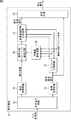
図1は、本技術を適用した符号化装置の一実施の形態の構成例を示す図である。
<First Embodiment>
[Configuration Example of Encoding Device]
FIG. 1 is a diagram illustrating a configuration example of an embodiment of an encoding device to which the present technology is applied.
この符号化装置11は、音声信号である入力信号を符号化し、その結果得られた出力符号列を出力する。
The
符号化装置11は、サブバンド分割回路21、第一高域符号化回路22、低域通過フィルタ23、低域符号化回路24、低域復号回路25、サブバンド分割回路26、遅延回路27、遅延回路28、遅延回路29、第二高域符号化回路30、符号量調整回路31、符号量一時蓄積回路32、遅延回路33、および多重化回路34から構成される。
The
サブバンド分割回路21は、入力信号を複数のサブバンド信号に分割し、得られた低域サブバンド信号を第一高域符号化回路22へ供給するとともに、高域サブバンド信号を第一高域符号化回路22、および遅延回路29へ供給する。
The
例えば、入力信号全体の周波数帯域が、帯域幅の等しい複数の周波数帯域(以下、サブバンドと称する)に分割されて、入力信号が各サブバンドの信号(以下、サブバンド信号と称する)に分割される。そして、サブバンド信号のうち、高域側の所定のサブバンドのサブバンド信号が高域サブバンド信号とされ、高域側よりも周波数の低い低域側の所定のサブバンドのサブバンド信号が低域サブバンド信号とされる。 For example, the frequency band of the entire input signal is divided into a plurality of frequency bands (hereinafter referred to as subbands) having the same bandwidth, and the input signal is divided into signals of each subband (hereinafter referred to as subband signals). Is done. Of the subband signals, the subband signal of the predetermined subband on the high frequency side is the high frequency subband signal, and the subband signal of the predetermined subband on the low frequency side having a lower frequency than the high frequency side is the subband signal. A low-frequency subband signal is used.
第一高域符号化回路22は、サブバンド分割回路21から供給された低域サブバンド信号から得られる特徴量に基づき、高域サブバンド信号のパワーを推定するために用いられる推定係数を符号化し、その符号量(以下、高域符号量と称する)を低域符号化回路24、および遅延回路28へ供給する。
The first high
低域通過フィルタ23は、供給された入力信号をフィルタリングして、その結果得られた、入力信号の低域成分である低域信号を低域符号化回路24へ供給する。この低域信号は、低域側の各低域サブバンド信号からなる信号である。
The low-
低域符号化回路24は、入力信号の処理フレームで使用可能な符号量から、第一高域符号化回路22から供給された高域符号量を減じた符号量で、低域通過フィルタ23からの低域信号を符号化する。低域符号化回路24は、低域信号の符号化により得られた低域符号列を低域復号回路25、および遅延回路33へ供給する。
The low-
低域復号回路25は、低域符号化回路24から供給された低域符号列の復号を行い、その結果得られた復号低域信号をサブバンド分割回路26へ供給する。サブバンド分割回路26は、低域復号回路25から供給された復号低域信号を、低域側の複数のサブバンドのサブバンド信号(以下、復号低域サブバンド信号と称する)に分割し、遅延回路27へ供給する。ここで、復号低域サブバンド信号のサブバンドのそれぞれは、低域サブバンド信号のサブバンドのそれぞれと同じ周波数帯域とされる。
The low
遅延回路27は、サブバンド分割回路26からの復号低域サブバンド信号を遅延させ、第二高域符号化回路30へ供給する。遅延回路28は、第一高域符号化回路22からの高域符号量を一定の処理フレームだけ遅延させ、第二高域符号化回路30へ供給する。遅延回路29は、サブバンド分割回路21からの高域サブバンド信号を遅延させ、第二高域符号化回路30へ供給する。
The delay circuit 27 delays the decoded low band subband signal from the
第二高域符号化回路30は、遅延回路27から出力される復号低域サブバンド信号から得られる特徴量に基づき、遅延回路28で得られた高域符号量により定まる符号量以下になるように、遅延回路29からの高域サブバンド信号のパワーの推定係数を符号化する。第二高域符号化回路30は、推定係数を符号化して得られた高域符号列を多重化回路34へ供給するとともに、高域符号列の高域符号量を、符号量調整回路31へ供給する。
The second high
符号量調整回路31は、第二高域符号化回路30で得られた高域符号量が、遅延回路28を通して得られる第一高域符号化回路22の高域符号量未満であった場合、その剰余符号量を符号量一時蓄積回路32へ供給する。符号量一時蓄積回路32は、剰余符号量の蓄積を行なう。この剰余符号量は、次回以降の処理フレームで適宜使用される。
When the high frequency code amount obtained by the second high
遅延回路33は、低域符号化回路24で得られた低域符号列を一定の処理フレームだけ遅延させ、多重化回路34へ供給する。多重化回路34は、遅延回路33からの低域符号列と、第二高域符号化回路30からの高域符号列を多重化し、その結果得られた出力符号列を出力する。
The
[音質の向上について]
ところで、符号化装置11における符号化方式や、HE-AACといった符号化方式では、音声信号の高域成分の特徴的な情報が極めて少ない符号量で符号化され、人間の聴覚上歪が知覚されやすい周波数帯域である低域に、多くの符号量が割り当てられる。また、符号化装置11は、高域成分の信号の状態に応じて積極的に符号量を調整するため、高域符号量は処理フレームによって大きく変動することが多い。
[Improvement of sound quality]
By the way, in the encoding method in the
このような理由から、上述の符号化方式では、まず高域信号の符号化を行い、余った符号量で低域信号の符号化を行うのが一般的な構成とされている。 For this reason, in the above-described encoding method, it is a general configuration to first encode a high-frequency signal and encode a low-frequency signal with a surplus code amount.
また一方で、低域成分を用いて高域成分の符号化を行う符号化手法では、符号化装置11で扱う低域信号と、復号装置で扱う低域信号とが異なるという点が、高域信号の音質劣化の原因の一つになる。
On the other hand, in the encoding method for encoding the high frequency component using the low frequency component, the low frequency signal handled by the
すなわち、入力信号に対するサブバンド分割により、例えば図2に示すように、入力信号が低域と高域の各サブバンドに分割されたとする。なお、図2では、入力信号の各サブバンドのパワーが示されている。また、図中、横軸は周波数を示し、縦軸は各サブバンドのサブバンド信号のパワーを示している。 In other words, it is assumed that the input signal is divided into low-band and high-band sub-bands as shown in FIG. In FIG. 2, the power of each subband of the input signal is shown. In the figure, the horizontal axis indicates the frequency, and the vertical axis indicates the power of the subband signal of each subband.
図2の例では、入力信号の低域成分はサブバンドsb-3乃至サブバンドsbの4つのサブバンドに分割され、入力信号の高域成分は、サブバンドsb+1乃至サブバンドsb+12の12のサブバンドに分割されている。また、低域側の最も周波数の高いサブバンドsbの高域側に隣接するサブバンドが、高域側の最も周波数の低いサブバンドsb+1とされている。 In the example of FIG. 2, the low frequency component of the input signal is divided into four subbands of subbands sb-3 to sb, and the high frequency component of the input signal is subband sb + 1 to subband sb + 12. Are divided into 12 subbands. In addition, the subband adjacent to the high frequency side of the subband sb having the highest frequency on the low frequency side is the subband sb + 1 having the lowest frequency on the high frequency side.
ここで、各サブバンドにおける図中、横方向の実線が、それらのサブバンドのサブバンド信号(低域サブバンド信号または高域サブバンド信号)のパワーを示している。 Here, in the drawing for each subband, the solid line in the horizontal direction indicates the power of the subband signals (low band subband signal or high band subband signal) of those subbands.
このような入力信号の低域成分が符号化されて、符号化により得られる低域符号列が復号装置で復号されたとする。この場合、低域符号列を復号して得られる復号低域信号に対してサブバンド分割を行なうと、復号低域信号は、例えば図3に示すように、サブバンドsb-3乃至サブバンドsbの4つのサブバンドに分割される。 It is assumed that such a low frequency component of the input signal is encoded and a low frequency code string obtained by the encoding is decoded by the decoding device. In this case, when subband division is performed on a decoded lowband signal obtained by decoding a lowband code string, the decoded lowband signal is subband sb-3 to subband sb as shown in FIG. 3, for example. Are divided into four subbands.
なお、図3において、横軸は周波数を示し、縦軸は各サブバンドのサブバンド信号のパワーを示している。また、各サブバンドの横方向の実線は、入力信号の符号化前の各サブバンド信号のパワーを示しており、各サブバンドの横方向の一点鎖線は、復号装置で得られた復号低域信号を構成する復号低域サブバンド信号のパワーを示している。 In FIG. 3, the horizontal axis indicates the frequency, and the vertical axis indicates the power of the subband signal of each subband. In addition, the horizontal solid line of each subband indicates the power of each subband signal before encoding of the input signal, and the horizontal alternate long and short dash line of each subband indicates the decoding low band obtained by the decoding device. The power of the decoded low-frequency subband signal that constitutes the signal is shown.
図3に示されるように、復号装置において得られる復号低域信号は、符号化誤差を含んだものであるため、結果として、復号低域サブバンド信号のパワーは、符号化装置11における低域サブバンド信号のパワーと異なるものとなる。
As shown in FIG. 3, since the decoded low frequency signal obtained in the decoding device includes an encoding error, as a result, the power of the decoded low frequency subband signal is low in the
そのため、例えば低域サブバンド信号のパワーを特徴量として、複数の推定係数のうち、特徴量と高域サブバンド信号とから、最も高精度に高域サブバンド信号のパワーを推定できる推定係数を選択し、復号装置に出力すると音質の劣化が生じる恐れがある。 Therefore, for example, using the power of a low-frequency subband signal as a feature quantity, among the multiple estimation coefficients, an estimation coefficient that can estimate the power of the high-frequency subband signal with the highest accuracy from the feature quantity and the high-frequency subband signal. If selected and output to a decoding device, there is a risk of sound quality degradation.
すなわち、符号化側では、復号装置で得られる復号低域サブバンド信号とは異なる低域サブバンド信号と、高域サブバンド信号および推定係数とが用いられて高域サブバンド信号のパワーが推定され、その推定結果から、最も適切な推定係数が選択される。したがって、このように選択された推定係数を用いても、符号化側と復号側とで高域サブバンド信号のパワーの推定に用いられる低域成分が異なれば、高精度に高域サブバンド信号のパワーを推定できるとは限らない。 That is, on the encoding side, the power of the high frequency subband signal is estimated by using the low frequency subband signal different from the decoded low frequency subband signal obtained by the decoding device, the high frequency subband signal, and the estimation coefficient. The most appropriate estimation coefficient is selected from the estimation result. Therefore, even if the estimation coefficient selected in this way is used, if the low-frequency component used for estimating the power of the high-frequency subband signal differs between the encoding side and the decoding side, the high-frequency subband signal is accurately detected. It is not always possible to estimate the power of.
そこで、より正確な推定を行うことによって音質を向上させるためには、符号化装置にも低域符号列を復号する復号装置を内蔵し、そこで得られる復号低域信号を用いて高域の符号化を行うことが必要である。 Therefore, in order to improve sound quality by performing more accurate estimation, the encoding device also includes a decoding device that decodes the low-frequency code string, and the decoded low-frequency signal obtained there is used to encode the high-frequency code. It is necessary to make it.
符号化装置11では、低域復号回路25が設けられており、この低域復号回路25により低域符号列が復号され、これにより得られた復号低域サブバンド信号が用いられて高域の符号化が行なわれるため、復号により得られる音声の音質を向上させることができる。
The
[符号化処理の説明]
次に、符号化装置11の動作について説明する。符号化装置11に入力信号が供給され、入力信号の符号化が指示されると、符号化装置11は符号化処理を行って、入力信号を符号化する。以下、図4のフローチャートを参照して、符号化装置11による符号化処理について説明する。
[Description of encoding process]
Next, the operation of the
ステップS11において、サブバンド分割回路21は、供給された入力信号を、所定の帯域幅を持つ複数のサブバンド信号に等分割する。ここで得られたサブバンド信号のうちの低域側の特定の範囲のサブバンド信号が低域サブバンド信号とされ、高域側の特定の範囲のサブバンド信号が高域サブバンド信号とされる。
In step S11, the
サブバンド分割回路21は、サブバンド分割により得られた低域サブバンド信号を第一高域符号化回路22に供給し、高域サブバンド信号を第一高域符号化回路22および遅延回路29に供給する。
The
例えば、高域サブバンド信号のサブバンドの範囲は、入力信号の性質やビットレートなどに応じて符号化装置11側で設定される。また、低域サブバンド信号のサブバンドの範囲は、高域サブバンド信号の最低域のサブバンドより一つ低域側のサブバンドを、低域サブバンド信号の最高域のサブバンドとした、一定サブバンド数からなる周波数帯域とされる。このように、低域サブバンド信号と高域サブバンド信号がカバーするサブバンドの範囲は、符号化装置11と復号装置で同一である。
For example, the subband range of the high frequency subband signal is set on the
ステップS12において、第一高域符号化回路22は、サブバンド分割回路21から供給された低域サブバンド信号からの推定に基づき高域の符号化を行なって、高域符号量を算出し、高域符号量を低域符号化回路24および遅延回路28に供給する。
In step S12, the first high
例えば、第一高域符号化回路22は、サブバンド分割回路21から供給された各サブバンドの低域サブバンド信号のパワー(以下、低域サブバンドパワーと称する)を特徴量として算出する。また、第一高域符号化回路22は、複数の推定係数ごとに、低域サブバンドパワーと推定係数とから高域の各サブバンドの高域サブバンド信号のパワーの推定値(以下、擬似高域サブバンドパワーと称する)を算出する。具体的には、サブバンドごとの推定係数が用いられて各サブバンドの低域サブバンドパワーが線形結合されて、所定のサブバンドの擬似高域サブバンドパワーとされる。
For example, the first high
そして、第一高域符号化回路22は、擬似高域サブバンドパワーと、実際の高域サブバンド信号のパワー(以下、高域サブバンドパワーと称する)とを比較して、複数の推定係数のうち、最も精度よく入力信号の高域を推定できる推定係数を選択する。第一高域符号化回路22は、選択された推定係数を特定する係数インデックスの符号量を、符号化された高域成分の符号量、つまり高域符号量とする。
Then, the first high
なお、低域信号を用いて高域の符号化を行う符号化手法であれば、符号化手法は様々な手法をとることが可能である。また、ステップS12における高域符号化処理では、高域符号量の算出ができれば、実際の符号化は行わなくともよい。さらに、計算処理量を低減させたい場合は、処理の一部を省略して高域符号量の見積もり値を取得するような構成もとることができる。 Note that various encoding methods can be used as long as the encoding method performs high-frequency encoding using low-frequency signals. In the high frequency encoding process in step S12, actual encoding may not be performed if the high frequency code amount can be calculated. Furthermore, when it is desired to reduce the calculation processing amount, a configuration in which a part of the processing is omitted and an estimated value of the high frequency code amount is obtained can be employed.
ステップS13において、低域通過フィルタ23は、供給された入力信号に対するフィルタ処理を行うことで、入力信号の低域周波数成分を通過させて低域信号を生成し、低域符号化回路24に出力する。このフィルタ処理に用いるフィルタの遮断周波数としては、任意の周波数を設定することが可能であるが、本実施の形態では、上述の低域サブバンド信号の上端の周波数に対応して遮断周波数が設定される。
In step S <b> 13, the low-
ステップS14において、低域符号化回路24は、予め定められた処理フレーム全体で使用可能な符号量から、第一高域符号化回路22から供給された高域符号量を減じた符号量で、低域通過フィルタ23からの低域信号を符号化する。低域符号化回路24は、低域信号の符号化により得られた低域符号列を、低域復号回路25および遅延回路33に出力する。
In step S14, the low
ステップS15において、低域復号回路25は、低域符号化回路24から供給された低域符号列の復号を行い、これにより得られた復号低域信号をサブバンド分割回路26に出力する。なお、符号化装置11では、低域信号の符号化及び復号を行う符号化方式は様々な方式をとることができ、例えば、ACELP(Algebraic Code Excited Linear Prediction)や、AAC(Advanced Audio Coding)などを採用することができる。
In step S <b> 15, the low
ステップS16において、サブバンド分割回路26は、低域復号回路25から供給された復号低域信号を複数のサブバンドの復号低域サブバンド信号に分割し、遅延回路27に出力する。このサブバンド分割における、各サブバンドの下端及び上端の周波数は、ステップS11においてサブバンド分割回路21が行うサブバンド分割と同一とされる。つまり、復号低域サブバンド信号の各サブバンドは、低域サブバンド信号の各サブバンドと同じ周波数帯域とされる。
In step S <b> 16, the
ステップS17において、遅延回路27は、サブバンド分割回路26から供給された復号低域サブバンド信号を特定の時間サンプルだけ遅延させ、第二高域符号化回路30に供給する。
In step S <b> 17, the delay circuit 27 delays the decoded low frequency subband signal supplied from the
遅延回路27での遅延量は、低域信号、高域信号、高域符号量、低域符号列の同期をとるためのものであり、低域、高域それぞれの符号化方式によって、適切な値を設定する必要がある。当然、符号化方式の構成によっては、各遅延回路の遅延量が0である場合もあり得る。他の遅延回路28,遅延回路29、および遅延回路33の説明は、遅延回路27が果たす機能と同等であるので、ここでは説明を省略する。
The delay amount in the delay circuit 27 is for synchronizing the low-frequency signal, the high-frequency signal, the high-frequency code amount, and the low-frequency code string. It is necessary to set a value. Naturally, the delay amount of each delay circuit may be zero depending on the configuration of the encoding method. The description of the
ステップS18において、第二高域符号化回路30は、遅延回路27から出力される復号低域サブバンド信号から得られる特徴量に基づき、遅延回路28から供給された高域符号量以下の符号量になるように、遅延回路29から供給された高域サブバンド信号のパワーの推定係数を符号化する。
In step S <b> 18, the second high
例えば、第二高域符号化回路30は、遅延回路28から供給された高域符号量に、符号量一時蓄積回路32に蓄積されている剰余符号量を加算して、補正された高域符号量(以下、補正高域符号量と称する)を算出する。このとき、余剰符号量が、高域符号量の予め定められた上限補正量以上である場合には、高域符号量に上限補正量が加算されて得られる符号量が、補正高域符号量とされる。
For example, the second high
高域符号量の補正時において、符号量調整回路31は、符号量一時蓄積回路32に蓄積されている剰余符号量に基づいて、その剰余符号量または上限補正量を示す情報を、第二高域符号化回路30に供給する。また、符号量調整回路31は、符号量一時蓄積回路32の剰余符号量の更新を行なう。例えば、上限補正量を示す情報が第二高域符号化回路30に供給された場合、符号量調整回路31は、剰余符号量から上限補正量を減算して得られる符号量を、更新後の剰余符号量とする。
At the time of correction of the high frequency code amount, the code amount adjustment circuit 31 stores information indicating the remainder code amount or the upper limit correction amount based on the remainder code amount stored in the code amount
さらに、第二高域符号化回路30は、高域サブバンド信号と復号低域サブバンド信号とに基づいて、高域符号列の符号量が補正高域符号量以下となるように、処理対象のフレームの音声信号の高域成分を符号化する。
Further, the second high
例えば、第二高域符号化回路30は、処理対象のフレームをいくつかの区間に分割し、ステップS12の処理と同様の処理を行って、各区間の推定係数を選択する。
For example, the second high
すなわち、第二高域符号化回路30は、復号低域サブバンド信号から復号低域サブバンドパワーを求め、推定係数ごとに、復号低域サブバンドパワーと推定係数とから擬似高域サブバンドパワーを算出する。そして、第二高域符号化回路30は、擬似高域サブバンドパワーと、高域サブバンド信号の高域サブバンドパワーとを比較して、最も精度よく入力信号の高域を推定できる推定係数を選択する。第二高域符号化回路30は、処理対象のフレームを構成する各区間の推定係数を示す係数インデックスからなる符号列を、高域符号列とする。
That is, the second
ここで、高域符号列の符号量は、例えば処理対象のフレームを構成する区間の数を変化させることで調整が行なわれる。また、連続する区間で同じ推定係数が選択された場合には、それらの区間を特定する情報と、選択された1つの推定係数の係数インデックスとからなる情報が高域符号列を構成する符号列とされるようにして、高域符号列の符号量の調整が行なわれるようにしてもよい。 Here, the code amount of the high frequency code string is adjusted by changing the number of sections constituting the frame to be processed, for example. In addition, when the same estimation coefficient is selected in consecutive sections, information including information identifying these sections and the coefficient index of one selected estimation coefficient is a code string that forms a high-frequency code string In this manner, the code amount of the high frequency code string may be adjusted.
なお、高域符号量の補正が行なわれないようにしてもよい。そのような場合には、高域符号列が遅延回路28から出力される高域符号量以下の符号量となるように、高域の符号化が行なわれる。
Note that the high-frequency code amount may not be corrected. In such a case, high frequency encoding is performed so that the high frequency code string has a code amount equal to or less than the high frequency code amount output from the
また、ステップS18での符号化方式は、ステップS12における処理の符号化方式と同様に、低域信号を用いて高域の符号化を行う符号化手法であれば、符号化手法は様々な手法をとることができるが、少なくとも、ステップS12における符号化方式と同一の符号化規格に基づくものである必要がある。但し、ステップS18における符号化処理がステップS12における符号化処理と明確に異なるのは、第一に、ステップS12において算出された高域符号量以下になるように符号化する必要がある点、第二に、高域の符号化を行うために必要な低域の信号は、復号後の低域信号(復号低域サブバンド信号)である点である。 In addition, the encoding method in step S18 may be various methods as long as it is an encoding method that performs high-frequency encoding using a low-frequency signal, similar to the encoding method of processing in step S12. However, it should be based on at least the same encoding standard as the encoding method in step S12. However, the encoding process in step S18 is clearly different from the encoding process in step S12. First, the encoding process needs to be less than the high frequency code amount calculated in step S12. Secondly, the low frequency signal necessary for performing high frequency encoding is a low frequency signal after decoding (decoded low frequency sub-band signal).
このように、第一高域符号化回路22で高域の仮の符号化を行なって、高域符号量を定めておき、高域符号列が高域符号量により定まる符号量以下となるように、実際の高域の符号化を行なうことで、高域の符号化を行なう前に、高域符号列の符号量を確定させることができる。これにより、低域符号列に割り当てられる符号量を求めることができるので、直ちに低域信号の符号化を行なうことができ、より効率的に入力信号の符号化を行なうことが可能となる。
As described above, the first high
ステップS19において、第二高域符号化回路30は、符号化により得られた高域符号列の符号量が補正高域符号量未満であるか否かを判定する。
In step S19, the second high
ステップS19において、補正高域符号量未満でないと判定された場合、つまり高域符号列の符号量が補正高域符号量と一致する場合、符号の剰余は発生しないので、処理はステップS23に進む。このとき、第二高域符号化回路30は、高域の符号化により得られた高域符号列を多重化回路34に供給する。
If it is determined in step S19 that the code amount is not less than the corrected high frequency code amount, that is, if the code amount of the high frequency code string matches the corrected high frequency code amount, no code remainder is generated, and the process proceeds to step S23. . At this time, the second high
これに対して、ステップS19において、補正高域符号量未満であると判定された場合、ステップS20において、符号量調整回路31は、高域符号列の符号量と、補正高域符号量との差分の符号量一時蓄積回路32への蓄積を行なう。すなわち、高域符号列の符号量と補正高域符号量の差の分の符号量が、符号量一時蓄積回路32に蓄積されている剰余符号量に加算されていき、剰余符号量が更新される。
On the other hand, if it is determined in step S19 that it is less than the corrected high frequency code amount, in step S20, the code amount adjustment circuit 31 calculates the code amount of the high frequency code string and the corrected high frequency code amount. The difference is stored in the code amount
このような符号量一時蓄積回路32は、AACにおいてもビットリゾルバという名称で使われており、処理フレーム間での符号量の調整が行なわれる。なお、符号化装置11は、余剰符号量は、高域符号化のために用いられる構成になっているが、低域信号の符号化方式において、同様な機能を有する回路が存在する場合は、共通に使うことも可能である。すなわち、剰余符号量が高域符号列または低域符号列の何れか一方の符号量の調整にのみ用いられてもよいし、それらの両方の符号量の調整に用いられてもよい。
Such a code amount
ステップS21において、符号量調整回路31は、符号量一時蓄積回路32に蓄積している剰余符号量が予め定められた上限に達したか否かを判定する。
In step S21, the code amount adjustment circuit 31 determines whether or not the residual code amount stored in the code amount
例えば、符号量一時蓄積回路32では、剰余符号量とすることの可能な符号量の上限(以下、上限符号量と称する)が予め定められている。符号量調整回路31は、ステップS20で開始した、高域符号列の符号量と補正高域符号量の差分の符号量一時蓄積回路32への蓄積時に、剰余符号量が上限符号量に達した場合、ステップS21において剰余符号量が上限に達したと判定する。
For example, in the code amount
ステップS21において、剰余符号量が上限に達していないと判定された場合、高域符号列の符号量と、補正高域符号量の差分が、全て剰余符号量に加算され、剰余符号量が更新される。そして、その後、第二高域符号化回路30は、高域の符号化により得られた高域符号列を多重化回路34に供給し、処理はステップS23に進む。
If it is determined in step S21 that the residual code amount has not reached the upper limit, the difference between the code amount of the high frequency code string and the corrected high frequency code amount is all added to the residual code amount, and the residual code amount is updated. Is done. After that, the second high
一方、ステップS21において、剰余符号量が上限に達したと判定された場合、ステップS22において、第二高域符号化回路30は、高域符号列に対するゼロ詰めを行なう。
On the other hand, if it is determined in step S21 that the remainder code amount has reached the upper limit, in step S22, the second high
高域符号列の符号量と、補正高域符号量との差分を剰余符号量に加算していくときに、剰余符号量が上限符号量に達した場合、高域符号列の符号量と、補正高域符号量との差分のうち、まだ剰余符号量への加算が行なわれていない未処理の符号量が余ることになる。この未処理の符号量は、剰余符号量に加算することはできないので、第二高域符号化回路30は、この未処理の符号量の分だけ、高域符号列の最後尾に符号「0」を付加し、未処理の符号量を見かけ上、高域符号列の生成に用いたこととする。なお、復号時においては、高域符号列の最後尾に付加された符号「0」は、入力信号の復号には用いられない。
When the difference between the code amount of the high frequency code string and the corrected high frequency code amount is added to the remainder code amount, if the remainder code amount reaches the upper limit code amount, the code amount of the high frequency code string, Of the difference from the corrected high frequency code amount, an unprocessed code amount that has not yet been added to the remainder code amount remains. Since this unprocessed code amount cannot be added to the remainder code amount, the second high
第二高域符号化回路30は、高域符号列の最後尾に符号「0」を付加するゼロ詰めを行なうと、ゼロ詰め後の高域符号列を多重化回路34に供給し、処理はステップS23に進む。
When the second high
ステップS19において補正高域符号量未満でないと判定されたか、ステップS21において剰余符号量が上限に達していないと判定されたか、またはステップS22においてゼロ詰めが行なわれると、ステップS23の処理が行われる。 If it is determined in step S19 that it is not less than the corrected high frequency code amount, it is determined in step S21 that the residual code amount has not reached the upper limit, or zero padding is performed in step S22, the process of step S23 is performed. .
すなわち、ステップS23において、多重化回路34は、遅延回路33からの低域符号列と、第二高域符号化回路30からの高域符号列とを多重化して出力符号列を生成し、出力符号列を出力する。このとき、多重化回路34は、低域符号列や高域符号列とともに、入力信号の低域側の上端と下端のサブバンドを示すインデックスも多重化する。このようにして出力符号列が出力されると、符号化処理は終了する。
That is, in step S23, the multiplexing
以上のように、符号化装置11は、高域符号量を求め、この高域符号量から定まる符号量で低域信号を符号化するとともに、低域符号列を復号して得られた復号低域信号や高域符号量に基づいて、高域成分の符号化を行なう。
As described above, the
このように、高域の仮の符号化を行なって高域符号量を定めておき、高域符号列が高域符号量により定まる符号量以下となるように、実際の高域の符号化を行なうことで、高域の符号化を行なう前に、高域符号列の符号量を確定させることができる。これにより、低域符号列に割り当てられる符号量を求めることができ、直ちに低域信号の符号化を行なうことができる。したがって、符号化装置11の構成の複雑化を避け、かつ計算量の増大を避ける効率的な符号化を行なうことができる。しかも、復号後の低域の信号を用いて高域の符号化を行なうことにより、より適切な推定係数を選択することができ、音声の音質を向上させることができる。
In this way, high-frequency provisional encoding is performed to determine the high-frequency code amount, and actual high-frequency encoding is performed so that the high-frequency code string is equal to or less than the code amount determined by the high-frequency code amount. By doing so, the code amount of the high frequency code string can be determined before encoding the high frequency band. Thereby, the code amount allocated to the low frequency code string can be obtained, and the low frequency signal can be immediately encoded. Therefore, it is possible to perform efficient encoding that avoids complication of the configuration of the
[復号装置の構成例]
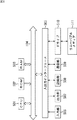
次に、符号化装置11から出力される出力符号列を入力符号列として入力し、入力符号列の復号を行なう復号装置について説明する。復号装置は、例えば図5に示すように構成される。
[Configuration Example of Decoding Device]
Next, a decoding apparatus that inputs an output code string output from the
復号装置61は、非多重化回路71、低域復号回路72、サブバンド分割回路73、特徴量算出回路74、高域復号回路75、復号高域サブバンドパワー算出回路76、復号高域信号生成回路77、および合成回路78から構成される。
The decoding device 61 includes a
非多重化回路71は、入力符号列を高域符号列と低域符号列に非多重化し、低域符号列を低域復号回路72に供給し、高域符号列を高域復号回路75に供給する。
The
低域復号回路72は、非多重化回路71からの低域符号列の復号を行い、その結果得られた復号低域信号を、サブバンド分割回路73、および合成回路78に供給する。
The low
サブバンド分割回路73は、低域復号回路72からの復号低域信号を、所定の帯域幅を持つ複数のサブバンド信号に等分割し、得られたサブバンド信号(復号低域サブバンド信号)を、特徴量算出回路74および復号高域信号生成回路77に供給する。
The
特徴量算出回路74は、サブバンド分割回路73からの復号低域サブバンド信号を用いて特徴量を算出し、復号高域サブバンドパワー算出回路76に供給する。
The feature
高域復号回路75は、係数インデックスと推定係数とを対応付けて記録しており、非多重化回路71からの高域符号列の復号を行い、その結果得られた係数インデックスにより特定される推定係数を復号高域サブバンドパワー算出回路76に供給する。
The high
復号高域サブバンドパワー算出回路76は、特徴量算出回路74からの特徴量と、高域復号回路75からの推定係数とに基づいて、入力信号の高域側の各サブバンドの高域サブバンドパワーの推定値である復号高域サブバンドパワーを算出し、復号高域信号生成回路77に供給する。
The decoded high band sub-band
復号高域信号生成回路77は、サブバンド分割回路73からの復号低域サブバンド信号と、復号高域サブバンドパワー算出回路76からの復号高域サブバンドパワーとに基づいて、復号高域信号を生成し、合成回路78に供給する。合成回路78は、低域復号回路72からの復号低域信号と、復号高域信号生成回路77からの復号高域信号とを合成し、出力信号として出力する。
The decoded high band
[復号処理の説明]
次に、復号装置61の動作について説明する。復号装置61は、符号化装置11から出力符号列が供給されてくると、その出力符号列を入力符号列として復号処理を行い、出力信号を出力する。以下、図6のフローチャートを参照して、復号装置61による復号処理について説明する。
[Description of decryption processing]
Next, the operation of the decoding device 61 will be described. When the output code string is supplied from the
ステップS51において、非多重化回路71は、入力符号列を高域符号列と低域符号列に非多重化し、低域符号列を低域復号回路72に供給するとともに、高域符号列を高域復号回路75に供給する。このとき、非多重化回路71は、必要に応じて非多重化により得られた、入力信号の低域側の上端と下端のサブバンドを示すインデックスを、低域復号回路72を介してサブバンド分割回路73に供給する。これにより、サブバンド分割回路73では、低域の各サブバンドをどのような周波数帯域とすればよいかを特定できる。
In step S51, the
ステップS52において、低域復号回路72は、非多重化回路71からの低域符号列の復号を行い、その結果得られた復号低域信号を、サブバンド分割回路73、および合成回路78に供給する。
In step S 52, the low
ステップS53において、サブバンド分割回路73は、必要に応じて非多重化回路71からのインデックスを用いて、低域復号回路72からの復号低域信号を複数の復号低域サブバンド信号に分割し、特徴量算出回路74および復号高域信号生成回路77に供給する。
In step S53, the
ステップS54において、特徴量算出回路74は、サブバンド分割回路73からの復号低域サブバンド信号を用いて特徴量を算出し、復号高域サブバンドパワー算出回路76に供給する。例えば、特徴量として、各サブバンドの復号低域サブバンド信号のパワーである復号低域サブバンドパワーが算出される。
In step S <b> 54, the feature
ステップS55において、高域復号回路75は、非多重化回路71からの高域符号列の復号を行い、その結果得られた係数インデックスにより特定される推定係数を復号高域サブバンドパワー算出回路76に出力する。
In step S55, the high
ステップS56において、復号高域サブバンドパワー算出回路76は、特徴量算出回路74からの特徴量と、高域復号回路75からの推定係数とに基づいて、高域の各サブバンドの復号高域サブバンドパワーを算出し、復号高域信号生成回路77に供給する。
In step S56, the decoded high frequency sub-band
例えば、サブバンドごとの推定係数が用いられて、特徴量としての各サブバンドの復号低域サブバンドパワーが線形結合されて、所定のサブバンドの復号高域サブバンドパワーとされる。 For example, the estimated coefficient for each subband is used, and the decoded low band subband power of each subband as the feature quantity is linearly combined to obtain the decoded high band subband power of a predetermined subband.
ステップS57において、復号高域信号生成回路77は、サブバンド分割回路73からの復号低域サブバンド信号と、復号高域サブバンドパワー算出回路76からの復号高域サブバンドパワーとに基づいて、復号高域信号を生成し、合成回路78に供給する。
In step S57, the decoded highband
ステップS58において、合成回路78は、低域復号回路72からの復号低域信号と、復号高域信号生成回路77からの復号高域信号とを合成し、出力信号として出力する。この出力信号は、推定係数を用いて予測された高域成分と、復号により得られた低域成分とからなる音声信号である。
In step S58, the synthesizing
出力信号が生成されて出力されると、復号処理は終了する。このようにして復号装置61は入力符号列を非多重化し、高域符号列から得られる推定係数を用いて高域成分を推定し、出力信号を生成する。このように推定係数を用いて高域成分を推定することで、より効率よく復号を行なうことができ、復号で得られる音声の音質も向上させることができる。 When the output signal is generated and output, the decoding process ends. In this way, the decoding device 61 demultiplexes the input code string, estimates the high frequency component using the estimation coefficient obtained from the high frequency code string, and generates an output signal. By estimating the high frequency component using the estimation coefficient in this way, decoding can be performed more efficiently, and the sound quality of speech obtained by decoding can be improved.
〈変形例〉
[符号化装置の構成例]
なお、以上においては、符号化装置11で、高域符号量や高域サブバンド信号等の各種の信号や情報が、必要に応じて遅延される場合について説明したが、特に遅延させる必要がない場合には、符号化装置に遅延回路が設けられないようにしてもよい。
<Modification>
[Configuration Example of Encoding Device]
In the above description, the case where various signals and information such as a high frequency code amount and a high frequency subband signal are delayed as necessary in the
そのような場合、符号化装置は例えば図7に示すように構成される。なお、図7において、図1における場合と対応する部分には同一の符号を付してあり、その説明は適宜省略する。 In such a case, the encoding device is configured as shown in FIG. 7, for example. In FIG. 7, parts corresponding to those in FIG. 1 are denoted by the same reference numerals, and description thereof is omitted as appropriate.
図7の符号化装置111は、高域通過フィルタ121、第一高域符号化回路22、低域通過フィルタ23、低域符号化回路24、低域復号回路25、第二高域符号化回路30、および多重化回路34から構成される。
7 includes a high-
高域通過フィルタ121は、供給された入力信号に対してフィルタ処理を行って、入力信号から高域成分である高域信号を抽出し、第一高域符号化回路22および第二高域符号化回路30に供給する。低域通過フィルタ23は、供給された入力信号に対してフィルタ処理を行って、入力信号から低域成分である低域信号を抽出し、第一高域符号化回路22および低域符号化回路24に供給する。
The high-
第一高域符号化回路22は、高域通過フィルタ121からの高域信号と、低域通過フィルタ23からの低域信号とに基づいて、入力信号の高域の符号化を行い、これにより得られた高域符号量を低域符号化回路24および第二高域符号化回路30に供給する。
The first high-
低域符号化回路24は、処理フレーム全体で使用可能な符号量から、第一高域符号化回路22からの高域符号量を減じた符号量で、低域通過フィルタ23からの低域信号を符号化し、これにより得られた低域符号列を低域復号回路25および多重化回路34に供給する。低域復号回路25は、低域符号化回路24からの低域符号列を復号し、その結果得られた復号低域信号を第二高域符号化回路30に供給する。
The low-
第二高域符号化回路30は、高域通過フィルタ121からの高域信号と、低域復号回路25からの復号低域信号とに基づき、第一高域符号化回路22からの高域符号量により定まる符号量以下になるように、入力信号の高域成分の符号化を行なう。第二高域符号化回路30は、高域の符号化により得られた高域符号列を多重化回路34に供給する。多重化回路34は、低域符号化回路24からの低域符号列と、第二高域符号化回路30からの高域符号列とを多重化し、得られた出力符号列を出力する。
The second high
上述した一連の処理は、ハードウェアにより実行することもできるし、ソフトウェアにより実行することもできる。一連の処理をソフトウェアにより実行する場合には、そのソフトウェアを構成するプログラムが、専用のハードウェアに組み込まれているコンピュータ、または、各種のプログラムをインストールすることで、各種の機能を実行することが可能な、例えば汎用のパーソナルコンピュータなどに、プログラム記録媒体からインストールされる。 The series of processes described above can be executed by hardware or can be executed by software. When a series of processing is executed by software, a program constituting the software may execute various functions by installing a computer incorporated in dedicated hardware or various programs. For example, it is installed from a program recording medium in a general-purpose personal computer or the like.
図8は、上述した一連の処理をプログラムにより実行するコンピュータのハードウェアの構成例を示すブロック図である。 FIG. 8 is a block diagram illustrating an example of a hardware configuration of a computer that executes the above-described series of processes using a program.
コンピュータにおいて、CPU(Central Processing Unit)501,ROM(Read Only Memory)502,RAM(Random Access Memory)503は、バス504により相互に接続されている。
In a computer, a CPU (Central Processing Unit) 501, a ROM (Read Only Memory) 502, and a RAM (Random Access Memory) 503 are connected to each other by a
バス504には、さらに、入出力インターフェース505が接続されている。入出力インターフェース505には、キーボード、マウス、マイクロホンなどよりなる入力部506、ディスプレイ、スピーカなどよりなる出力部507、ハードディスクや不揮発性のメモリなどよりなる記録部508、ネットワークインターフェースなどよりなる通信部509、磁気ディスク、光ディスク、光磁気ディスク、或いは半導体メモリなどのリムーバブルメディア511を駆動するドライブ510が接続されている。
An input /
以上のように構成されるコンピュータでは、CPU501が、例えば、記録部508に記録されているプログラムを、入出力インターフェース505及びバス504を介して、RAM503にロードして実行することにより、上述した一連の処理が行われる。
In the computer configured as described above, the
コンピュータ(CPU501)が実行するプログラムは、例えば、磁気ディスク(フレキシブルディスクを含む)、光ディスク(CD-ROM(Compact Disc-Read Only Memory),DVD(Digital Versatile Disc)等)、光磁気ディスク、もしくは半導体メモリなどよりなるパッケージメディアであるリムーバブルメディア511に記録して、あるいは、ローカルエリアネットワーク、インターネット、デジタル衛星放送といった、有線または無線の伝送媒体を介して提供される。
The program executed by the computer (CPU 501) is, for example, a magnetic disk (including a flexible disk), an optical disk (CD-ROM (Compact Disc-Read Only Memory), DVD (Digital Versatile Disc), etc.), a magneto-optical disk, or a semiconductor. The program is recorded on a
そして、プログラムは、リムーバブルメディア511をドライブ510に装着することにより、入出力インターフェース505を介して、記録部508にインストールすることができる。また、プログラムは、有線または無線の伝送媒体を介して、通信部509で受信し、記録部508にインストールすることができる。その他、プログラムは、ROM502や記録部508に、あらかじめインストールしておくことができる。
The program can be installed in the
なお、コンピュータが実行するプログラムは、本明細書で説明する順序に沿って時系列に処理が行われるプログラムであっても良いし、並列に、あるいは呼び出しが行われたとき等の必要なタイミングで処理が行われるプログラムであっても良い。 The program executed by the computer may be a program that is processed in time series in the order described in this specification, or in parallel or at a necessary timing such as when a call is made. It may be a program for processing.
また、本技術の実施の形態は、上述した実施の形態に限定されるものではなく、本技術の要旨を逸脱しない範囲において種々の変更が可能である。 The embodiments of the present technology are not limited to the above-described embodiments, and various modifications can be made without departing from the gist of the present technology.
11 符号化装置, 22 第一高域符号化回路, 24 低域符号化回路, 25 低域復号回路, 30 第二高域符号化回路, 31 符号量調整回路, 32 符号量一時蓄積回路, 34 多重化回路
DESCRIPTION OF
Claims (7)
前記音声信号の前記低域成分を符号化し、低域符号列を生成する低域符号化部と、
前記低域符号列を復号する低域復号部と、
前記高域符号列の符号量が前記高域符号量以下の符号量となるように、前記低域符号列の復号で得られた復号低域成分と、前記高域成分とに基づいて、前記高域符号列を生成する第二高域符号化部と、
前記低域符号列と前記高域符号列とを多重化して出力符号列を生成する多重化部と
を備える符号化装置。 A first high frequency encoding unit that calculates a high frequency code amount that is a code amount of a high frequency code sequence for obtaining the high frequency component based on the low frequency component and the high frequency component of the audio signal ;
A low frequency encoding unit that encodes the low frequency component of the speech signal and generates a low frequency code sequence;
A low frequency decoding unit for decoding the low frequency code string;
Based on the decoded low frequency component obtained by decoding the low frequency code sequence and the high frequency component so that the code amount of the high frequency code sequence is equal to or less than the high frequency code amount, A second high frequency encoding unit that generates a high frequency code sequence;
An encoding device comprising: a multiplexing unit that multiplexes the low-frequency code string and the high-frequency code string to generate an output code string.
前記第二高域符号化部は、前記復号低域成分を構成する複数のサブバンドの復号低域サブバンド信号と、前記高域サブバンド信号とに基づいて前記高域符号列を生成する
請求項1に記載の符号化装置。 The first highband encoding unit is based on a plurality of subband lowband subband signals constituting the lowband component and a plurality of subband highband subband signals constituting the highband component. , Calculating the high frequency code amount,
The second highband encoding unit generates the highband code sequence based on a decoded lowband subband signal of a plurality of subbands constituting the decoded lowband component and the highband subband signal. Item 4. The encoding device according to Item 1.
請求項1に記載の符号化装置。 The encoding apparatus according to claim 1, further comprising a delay unit that delays the high-frequency code amount input to the second high-frequency encoding unit, the decoded low-frequency component, and the high-frequency component.
請求項1に記載の符号化装置。 When the code amount of the high frequency code string obtained by the second high frequency encoding unit is smaller than the high frequency code amount, the difference between the code amount of the high frequency code string and the high frequency code amount is calculated next time. The encoding apparatus according to claim 1, further comprising a code amount adjusting unit that controls accumulation of the residual code amount as a residual code amount that can be used in subsequent processing.
請求項4に記載の符号化装置。 The encoding apparatus according to claim 4, wherein the residual code amount is used for adjusting a code amount of at least one of the high-frequency code sequence or the low-frequency code sequence.
前記音声信号の前記低域成分を符号化し、低域符号列を生成する低域符号化部と、
前記低域符号列を復号する低域復号部と、
前記高域符号列の符号量が前記高域符号量以下の符号量となるように、前記低域符号列の復号で得られた復号低域成分と、前記高域成分とに基づいて、前記高域符号列を生成する第二高域符号化部と、
前記低域符号列と前記高域符号列とを多重化して出力符号列を生成する多重化部と
を備える符号化装置の符号化方法であって、
前記第一高域符号化部が前記高域符号量を算出し、
前記低域符号化部が前記低域成分を符号化し、
前記低域復号部が前記低域符号列を復号し、
前記第二高域符号化部が前記高域符号列を生成し、
前記多重化部が前記出力符号列を生成する
ステップを含む符号化方法。 A first high frequency encoding unit that calculates a high frequency code amount that is a code amount of a high frequency code sequence for obtaining the high frequency component based on the low frequency component and the high frequency component of the audio signal ;
A low frequency encoding unit that encodes the low frequency component of the speech signal and generates a low frequency code sequence;
A low frequency decoding unit for decoding the low frequency code string;
Based on the decoded low frequency component obtained by decoding the low frequency code sequence and the high frequency component so that the code amount of the high frequency code sequence is equal to or less than the high frequency code amount, A second high frequency encoding unit that generates a high frequency code sequence;
An encoding method of an encoding device comprising: a multiplexing unit that multiplexes the low-frequency code sequence and the high-frequency code sequence to generate an output code sequence,
The first high frequency encoding unit calculates the high frequency code amount,
The low frequency encoding unit encodes the low frequency component;
The low frequency decoding unit decodes the low frequency code string;
The second high frequency encoding unit generates the high frequency code string,
An encoding method including a step in which the multiplexing unit generates the output code string.
前記音声信号の前記低域成分を符号化し、低域符号列を生成し、
前記低域符号列を復号し、
前記高域符号列の符号量が前記高域符号量以下の符号量となるように、前記低域符号列の復号で得られた復号低域成分と、前記高域成分とに基づいて、前記高域符号列を生成し、
前記低域符号列と前記高域符号列とを多重化して出力符号列を生成する
ステップを含む処理をコンピュータに実行させるプログラム。 Based on the low frequency component and the high frequency component of the audio signal , a high frequency code amount that is a code amount of a high frequency code string for obtaining the high frequency component is calculated,
Encoding the low frequency component of the audio signal to generate a low frequency code string;
Decoding the low-frequency code sequence;
Based on the decoded low frequency component obtained by decoding the low frequency code sequence and the high frequency component so that the code amount of the high frequency code sequence is equal to or less than the high frequency code amount, Generate a high-frequency code string,
A program that causes a computer to execute processing including a step of generating an output code string by multiplexing the low-frequency code string and the high-frequency code string.
Priority Applications (12)
| Application Number | Priority Date | Filing Date | Title |
|---|---|---|---|
| JP2011078874A JP5704397B2 (en) | 2011-03-31 | 2011-03-31 | Encoding apparatus and method, and program |
| PCT/JP2012/057530 WO2012133195A1 (en) | 2011-03-31 | 2012-03-23 | Encoding apparatus and method, and program |
| TW101110250A TWI456568B (en) | 2011-03-31 | 2012-03-23 | Coding device and method, and program |
| EP12765534.8A EP2693430B1 (en) | 2011-03-31 | 2012-03-23 | Encoding apparatus and method, and program |
| KR1020137024507A KR20140005287A (en) | 2011-03-31 | 2012-03-23 | Encoding apparatus and method, and program |
| AU2012234115A AU2012234115B2 (en) | 2011-03-31 | 2012-03-23 | Encoding apparatus and method, and program |
| US14/006,148 US9437197B2 (en) | 2011-03-31 | 2012-03-23 | Encoding device, encoding method, and program |
| CA2829328A CA2829328A1 (en) | 2011-03-31 | 2012-03-23 | Encoding device, encoding method, and program |
| MX2013010879A MX2013010879A (en) | 2011-03-31 | 2012-03-23 | Encoding apparatus and method, and program. |
| RU2013143162/08A RU2013143162A (en) | 2011-03-31 | 2012-03-23 | ENCODING DEVICE, CODING METHOD AND PROGRAM |
| BR112013024392A BR112013024392A2 (en) | 2011-03-31 | 2012-03-23 | coding device and method, and, program |
| CN2012800146163A CN103443855A (en) | 2011-03-31 | 2012-03-23 | Encoding apparatus and method, and program |
Applications Claiming Priority (1)
| Application Number | Priority Date | Filing Date | Title |
|---|---|---|---|
| JP2011078874A JP5704397B2 (en) | 2011-03-31 | 2011-03-31 | Encoding apparatus and method, and program |
Publications (2)
| Publication Number | Publication Date |
|---|---|
| JP2012215599A JP2012215599A (en) | 2012-11-08 |
| JP5704397B2 true JP5704397B2 (en) | 2015-04-22 |
Family
ID=46930918
Family Applications (1)
| Application Number | Title | Priority Date | Filing Date |
|---|---|---|---|
| JP2011078874A Active JP5704397B2 (en) | 2011-03-31 | 2011-03-31 | Encoding apparatus and method, and program |
Country Status (12)
| Country | Link |
|---|---|
| US (1) | US9437197B2 (en) |
| EP (1) | EP2693430B1 (en) |
| JP (1) | JP5704397B2 (en) |
| KR (1) | KR20140005287A (en) |
| CN (1) | CN103443855A (en) |
| AU (1) | AU2012234115B2 (en) |
| BR (1) | BR112013024392A2 (en) |
| CA (1) | CA2829328A1 (en) |
| MX (1) | MX2013010879A (en) |
| RU (1) | RU2013143162A (en) |
| TW (1) | TWI456568B (en) |
| WO (1) | WO2012133195A1 (en) |
Families Citing this family (19)
| Publication number | Priority date | Publication date | Assignee | Title |
|---|---|---|---|---|
| JP5754899B2 (en) | 2009-10-07 | 2015-07-29 | ソニー株式会社 | Decoding apparatus and method, and program |
| JP5850216B2 (en) | 2010-04-13 | 2016-02-03 | ソニー株式会社 | Signal processing apparatus and method, encoding apparatus and method, decoding apparatus and method, and program |
| JP5609737B2 (en) | 2010-04-13 | 2014-10-22 | ソニー株式会社 | Signal processing apparatus and method, encoding apparatus and method, decoding apparatus and method, and program |
| JP5652658B2 (en) | 2010-04-13 | 2015-01-14 | ソニー株式会社 | Signal processing apparatus and method, encoding apparatus and method, decoding apparatus and method, and program |
| JP6075743B2 (en) | 2010-08-03 | 2017-02-08 | ソニー株式会社 | Signal processing apparatus and method, and program |
| JP5707842B2 (en) | 2010-10-15 | 2015-04-30 | ソニー株式会社 | Encoding apparatus and method, decoding apparatus and method, and program |
| JP5743137B2 (en) | 2011-01-14 | 2015-07-01 | ソニー株式会社 | Signal processing apparatus and method, and program |
| JP5975243B2 (en) | 2011-08-24 | 2016-08-23 | ソニー株式会社 | Encoding apparatus and method, and program |
| JP5942358B2 (en) | 2011-08-24 | 2016-06-29 | ソニー株式会社 | Encoding apparatus and method, decoding apparatus and method, and program |
| JP6037156B2 (en) | 2011-08-24 | 2016-11-30 | ソニー株式会社 | Encoding apparatus and method, and program |
| AU2013284703B2 (en) | 2012-07-02 | 2019-01-17 | Sony Corporation | Decoding device and method, encoding device and method, and program |
| EP3806498B1 (en) | 2013-09-17 | 2023-08-30 | Wilus Institute of Standards and Technology Inc. | Method and apparatus for processing audio signal |
| WO2015041070A1 (en) | 2013-09-19 | 2015-03-26 | ソニー株式会社 | Encoding device and method, decoding device and method, and program |
| CN105874819B (en) | 2013-10-22 | 2018-04-10 | 韩国电子通信研究院 | Generate the method and its parametrization device of the wave filter for audio signal |
| KR101627661B1 (en) | 2013-12-23 | 2016-06-07 | 주식회사 윌러스표준기술연구소 | Audio signal processing method, parameterization device for same, and audio signal processing device |
| KR20230042410A (en) | 2013-12-27 | 2023-03-28 | 소니그룹주식회사 | Decoding device, method, and program |
| CN106105269B (en) | 2014-03-19 | 2018-06-19 | 韦勒斯标准与技术协会公司 | Acoustic signal processing method and equipment |
| CN108307272B (en) | 2014-04-02 | 2021-02-02 | 韦勒斯标准与技术协会公司 | Audio signal processing method and apparatus |
| US11568884B2 (en) * | 2021-05-24 | 2023-01-31 | Invictumtech, Inc. | Analysis filter bank and computing procedure thereof, audio frequency shifting system, and audio frequency shifting procedure |
Family Cites Families (24)
| Publication number | Priority date | Publication date | Assignee | Title |
|---|---|---|---|---|
| JP3498375B2 (en) * | 1994-07-20 | 2004-02-16 | ソニー株式会社 | Digital audio signal recording device |
| DE60204038T2 (en) * | 2001-11-02 | 2006-01-19 | Matsushita Electric Industrial Co., Ltd., Kadoma | DEVICE FOR CODING BZW. DECODING AN AUDIO SIGNAL |
| CN1279512C (en) * | 2001-11-29 | 2006-10-11 | 编码技术股份公司 | Methods for improving high frequency reconstruction |
| CN102201242B (en) * | 2004-11-05 | 2013-02-27 | 松下电器产业株式会社 | Encoder, decoder, encoding method, and decoding method |
| MX2007012187A (en) * | 2005-04-01 | 2007-12-11 | Qualcomm Inc | Systems, methods, and apparatus for highband time warping. |
| JP4876574B2 (en) * | 2005-12-26 | 2012-02-15 | ソニー株式会社 | Signal encoding apparatus and method, signal decoding apparatus and method, program, and recording medium |
| EP2200026B1 (en) * | 2006-05-10 | 2011-10-12 | Panasonic Corporation | Encoding apparatus and encoding method |
| KR20070115637A (en) * | 2006-06-03 | 2007-12-06 | 삼성전자주식회사 | Method and apparatus for bandwidth extension encoding and decoding |
| US8010352B2 (en) * | 2006-06-21 | 2011-08-30 | Samsung Electronics Co., Ltd. | Method and apparatus for adaptively encoding and decoding high frequency band |
| JP4918841B2 (en) * | 2006-10-23 | 2012-04-18 | 富士通株式会社 | Encoding system |
| JP5141180B2 (en) | 2006-11-09 | 2013-02-13 | ソニー株式会社 | Frequency band expanding apparatus, frequency band expanding method, reproducing apparatus and reproducing method, program, and recording medium |
| CN101548318B (en) * | 2006-12-15 | 2012-07-18 | 松下电器产业株式会社 | Encoding device, decoding device, and method thereof |
| JP4984983B2 (en) * | 2007-03-09 | 2012-07-25 | 富士通株式会社 | Encoding apparatus and encoding method |
| KR101238239B1 (en) * | 2007-11-06 | 2013-03-04 | 노키아 코포레이션 | An encoder |
| WO2009059631A1 (en) | 2007-11-06 | 2009-05-14 | Nokia Corporation | Audio coding apparatus and method thereof |
| KR101413968B1 (en) | 2008-01-29 | 2014-07-01 | 삼성전자주식회사 | Method and apparatus for encoding audio signal, and method and apparatus for decoding audio signal |
| CN101853663B (en) | 2009-03-30 | 2012-05-23 | 华为技术有限公司 | Bit allocation method, encoding device and decoding device |
| ES2400661T3 (en) * | 2009-06-29 | 2013-04-11 | Fraunhofer-Gesellschaft zur Förderung der angewandten Forschung e.V. | Encoding and decoding bandwidth extension |
| JP5754899B2 (en) | 2009-10-07 | 2015-07-29 | ソニー株式会社 | Decoding apparatus and method, and program |
| JP5652658B2 (en) | 2010-04-13 | 2015-01-14 | ソニー株式会社 | Signal processing apparatus and method, encoding apparatus and method, decoding apparatus and method, and program |
| JP5850216B2 (en) | 2010-04-13 | 2016-02-03 | ソニー株式会社 | Signal processing apparatus and method, encoding apparatus and method, decoding apparatus and method, and program |
| JP5975243B2 (en) | 2011-08-24 | 2016-08-23 | ソニー株式会社 | Encoding apparatus and method, and program |
| JP5942358B2 (en) | 2011-08-24 | 2016-06-29 | ソニー株式会社 | Encoding apparatus and method, decoding apparatus and method, and program |
| JP6037156B2 (en) | 2011-08-24 | 2016-11-30 | ソニー株式会社 | Encoding apparatus and method, and program |
-
2011
- 2011-03-31 JP JP2011078874A patent/JP5704397B2/en active Active
-
2012
- 2012-03-23 MX MX2013010879A patent/MX2013010879A/en active IP Right Grant
- 2012-03-23 CA CA2829328A patent/CA2829328A1/en not_active Abandoned
- 2012-03-23 BR BR112013024392A patent/BR112013024392A2/en not_active Application Discontinuation
- 2012-03-23 KR KR1020137024507A patent/KR20140005287A/en not_active Application Discontinuation
- 2012-03-23 AU AU2012234115A patent/AU2012234115B2/en not_active Ceased
- 2012-03-23 RU RU2013143162/08A patent/RU2013143162A/en unknown
- 2012-03-23 EP EP12765534.8A patent/EP2693430B1/en active Active
- 2012-03-23 WO PCT/JP2012/057530 patent/WO2012133195A1/en active Application Filing
- 2012-03-23 CN CN2012800146163A patent/CN103443855A/en active Pending
- 2012-03-23 TW TW101110250A patent/TWI456568B/en not_active IP Right Cessation
- 2012-03-23 US US14/006,148 patent/US9437197B2/en active Active
Also Published As
| Publication number | Publication date |
|---|---|
| TWI456568B (en) | 2014-10-11 |
| KR20140005287A (en) | 2014-01-14 |
| BR112013024392A2 (en) | 2016-12-13 |
| AU2012234115A1 (en) | 2013-09-19 |
| MX2013010879A (en) | 2013-10-17 |
| CN103443855A (en) | 2013-12-11 |
| EP2693430A4 (en) | 2015-03-18 |
| EP2693430B1 (en) | 2019-05-08 |
| RU2013143162A (en) | 2015-03-27 |
| CA2829328A1 (en) | 2012-10-04 |
| US9437197B2 (en) | 2016-09-06 |
| AU2012234115B2 (en) | 2016-09-01 |
| EP2693430A1 (en) | 2014-02-05 |
| WO2012133195A1 (en) | 2012-10-04 |
| TW201246188A (en) | 2012-11-16 |
| US20140006037A1 (en) | 2014-01-02 |
| US20140172433A2 (en) | 2014-06-19 |
| JP2012215599A (en) | 2012-11-08 |
Similar Documents
| Publication | Publication Date | Title |
|---|---|---|
| JP5704397B2 (en) | Encoding apparatus and method, and program | |
| JP5942358B2 (en) | Encoding apparatus and method, decoding apparatus and method, and program | |
| US10546594B2 (en) | Signal processing apparatus and signal processing method, encoder and encoding method, decoder and decoding method, and program | |
| JP6037156B2 (en) | Encoding apparatus and method, and program | |
| US9659573B2 (en) | Signal processing apparatus and signal processing method, encoder and encoding method, decoder and decoding method, and program | |
| KR102055022B1 (en) | Encoding device and method, decoding device and method, and program | |
| US20110137659A1 (en) | Frequency Band Extension Apparatus and Method, Encoding Apparatus and Method, Decoding Apparatus and Method, and Program | |
| WO2013057895A1 (en) | Encoding device and encoding method | |
| JP2009103974A (en) | Masking level calculating device, encoder, masking level calculating method and masking level calculation program |
Legal Events
| Date | Code | Title | Description |
|---|---|---|---|
| A621 | Written request for application examination |
Free format text: JAPANESE INTERMEDIATE CODE: A621 Effective date: 20140227 |
|
| A131 | Notification of reasons for refusal |
Free format text: JAPANESE INTERMEDIATE CODE: A131 Effective date: 20141002 |
|
| A521 | Request for written amendment filed |
Free format text: JAPANESE INTERMEDIATE CODE: A523 Effective date: 20141121 |
|
| TRDD | Decision of grant or rejection written | ||
| A01 | Written decision to grant a patent or to grant a registration (utility model) |
Free format text: JAPANESE INTERMEDIATE CODE: A01 Effective date: 20150129 |
|
| A61 | First payment of annual fees (during grant procedure) |
Free format text: JAPANESE INTERMEDIATE CODE: A61 Effective date: 20150211 |
|
| R151 | Written notification of patent or utility model registration |
Ref document number: 5704397 Country of ref document: JP Free format text: JAPANESE INTERMEDIATE CODE: R151 |
|
| R250 | Receipt of annual fees |
Free format text: JAPANESE INTERMEDIATE CODE: R250 |
|
| R250 | Receipt of annual fees |
Free format text: JAPANESE INTERMEDIATE CODE: R250 |
|
| R250 | Receipt of annual fees |
Free format text: JAPANESE INTERMEDIATE CODE: R250 |