JP3774621B2 - Illumination device and photographing device - Google Patents
Illumination device and photographing device Download PDFInfo
- Publication number
- JP3774621B2 JP3774621B2 JP2000265769A JP2000265769A JP3774621B2 JP 3774621 B2 JP3774621 B2 JP 3774621B2 JP 2000265769 A JP2000265769 A JP 2000265769A JP 2000265769 A JP2000265769 A JP 2000265769A JP 3774621 B2 JP3774621 B2 JP 3774621B2
- Authority
- JP
- Japan
- Prior art keywords
- light
- optical member
- optical
- illumination
- emitted
- Prior art date
- Legal status (The legal status is an assumption and is not a legal conclusion. Google has not performed a legal analysis and makes no representation as to the accuracy of the status listed.)
- Expired - Fee Related
Links
Images


Classifications
-
- G—PHYSICS
- G03—PHOTOGRAPHY; CINEMATOGRAPHY; ANALOGOUS TECHNIQUES USING WAVES OTHER THAN OPTICAL WAVES; ELECTROGRAPHY; HOLOGRAPHY
- G03B—APPARATUS OR ARRANGEMENTS FOR TAKING PHOTOGRAPHS OR FOR PROJECTING OR VIEWING THEM; APPARATUS OR ARRANGEMENTS EMPLOYING ANALOGOUS TECHNIQUES USING WAVES OTHER THAN OPTICAL WAVES; ACCESSORIES THEREFOR
- G03B15/00—Special procedures for taking photographs; Apparatus therefor
- G03B15/02—Illuminating scene
- G03B15/03—Combinations of cameras with lighting apparatus; Flash units
- G03B15/05—Combinations of cameras with electronic flash apparatus; Electronic flash units
-
- H—ELECTRICITY
- H01—ELECTRIC ELEMENTS
- H01J—ELECTRIC DISCHARGE TUBES OR DISCHARGE LAMPS
- H01J61/00—Gas-discharge or vapour-discharge lamps
- H01J61/02—Details
- H01J61/025—Associated optical elements
-
- G—PHYSICS
- G03—PHOTOGRAPHY; CINEMATOGRAPHY; ANALOGOUS TECHNIQUES USING WAVES OTHER THAN OPTICAL WAVES; ELECTROGRAPHY; HOLOGRAPHY
- G03B—APPARATUS OR ARRANGEMENTS FOR TAKING PHOTOGRAPHS OR FOR PROJECTING OR VIEWING THEM; APPARATUS OR ARRANGEMENTS EMPLOYING ANALOGOUS TECHNIQUES USING WAVES OTHER THAN OPTICAL WAVES; ACCESSORIES THEREFOR
- G03B2215/00—Special procedures for taking photographs; Apparatus therefor
- G03B2215/05—Combinations of cameras with electronic flash units
- G03B2215/0503—Built-in units
- G03B2215/0507—Pop-up mechanisms
Landscapes
- Physics & Mathematics (AREA)
- General Physics & Mathematics (AREA)
- Stroboscope Apparatuses (AREA)
- Light Guides In General And Applications Therefor (AREA)
- Microscoopes, Condenser (AREA)
Description
【0001】
【発明の属する技術分野】
本発明は、照射範囲の変更が可能な照明装置およびこれを備えた撮影装置に関するものである。
【0002】
【従来の技術】
カメラ等の撮影装置に用いられている照明装置に関して、光源から様々な方向に射出した光束を効率よく必要照射画角内に集光させるために、従来種々の提案がなされている。
【0003】
特に近年では、従来、光源の前に配置されていたフレネルレンズのかわりに、プリズムやライトガイド等の全反射を利用した光学部材を配置することによって、集光効率の向上、小型化が図られている。
【0004】
ところで、近年、カメラ等の撮影装置においては、装置自体の小型・軽量化が進む一方、撮影レンズが高倍率ズーム化の傾向にある。一般的に、このような撮影装置の小型化かつ高倍率化によって、撮影レンズの開放Fナンバー値は徐々に大きくなる傾向にあり、補助光源を使用しないで撮影すると、手ぶれや被写体ぶれによる予想外のぶれ写真になったり、露出不足による失敗写真となることがある。この状況に対処するため、撮影装置に、補助光源としての照明装置を内蔵することが多い。
【0005】
しかし、このような事情のもと、照明装置の使用頻度が大幅に増加するとともに、1回の撮影に必要とされる発光量が増えるため、一般にワイド状態に対応して照射範囲が固定されており、テレ状態で不要範囲に照明が行われることとなるためにエネルギロスが大きい固定照射範囲の照明装置では十分に対応できない。
【0006】
このような背景から、撮影画角に対応した範囲だけに照明を行い、省電力化を図る照明装置として、照射範囲可変の照明装置が各種提案されている。特に、全反射を利用して発光効率を高めた照明装置もいくつか提案されている。
【0007】
例えば、特開平4−138439号公報にて本出願人が提案する照明装置では、照明装置の前面に、主に光源から射出光軸の側方に射出した光束を光学部材に入射させた後、全反射させ、一定方向に集光させる上下2つの面と、これとは別に正面に形成した正の屈折力を持つ面とで構成し、それぞれの面によって集光させた後、同一射出面から被写体側に射出させる集光光学系に対して、光学プリズムと光源の位置関係を相対的に変化させて全反射面での反射、透過を切り換え、照射範囲を変化させている。
【0008】
また、上記特開平8−262538号公報にて提案の照明装置では、光学プリズムを複数に分割し、上下に配置した光学プリズムを回動させて、照射範囲を変更している。
【0009】
【発明が解決しようとする課題】
しかしながら、上記公報にて提案の照明装置では、比較的光制御のし易い円筒状の放電発光管の径方向、すなわち光源の長手方向(左右方向)に直交する方向(上下方向)の集光拡散制御であり、光源の長手方向の集光拡散制御を行っていない。このため、照射範囲制御といっても、上下方向だけの照射範囲制御であり、必ずしも理想的な照射範囲制御が行われているわけではない。
【0010】
このため、本発明では、装置全体を小型化しつつ、光源からのエネルギを高い効率で利用でき、しかも光源の長手方向とこれに直交する方向の照射範囲制御を同時に行うのに適した照明装置を提供することを目的としている。
【0011】
【課題を解決するための手段】
上記の目的を達成するため、本発明では、発光ユニットから入射した照明光束を射出する、透光性を有した光学部材を備える照明装置であって、光学部材の少なくとも1つの端部に反射部を一体的に設け、発光ユニットと光学部材とを相対移動させることにより、光学部材から射出する照明光束のうち上記反射部で反射して射出した光束成分を増減させて照明光束の照射範囲を変更させるようにしている。
【0012】
すなわち、発光ユニットと光学部材とを相対移動させて、発光ユニットから射出される照明光束のうち光学部材の少なくとも1つの端方向に向かう光束を、上記反射部で全く反射させずに若しくは少し反射させて光学部材から射出させたり、上記反射部で多く反射させたりすることによって照射範囲を変更するようにし、簡単かつコンパクトな構成で、光源ユニットの長手方向の照射範囲制御に適した照明装置を実現している。
【0013】
また、上記反射部で反射した光束成分を増減させて照射範囲を変更させる構成であるため、上記増減を連続的に行って照射範囲を連続的に変更することも容易である。
【0014】
そして、上記反射部を発光ユニットにおける射出面の端部近傍を覆うように設けたり、上記反射部に全反射面を用いることにより、光源ユニットからのエネルギを高い効率で利用可能となる。
【0015】
しかも、上記光学部材に、上記反射部で反射して射出した光束成分を増減させて変更する照射範囲の変更方向(例えば、光源ユニットの長手方向)とは異なる方向(例えば、長手方向に直交する方向)における照明光束の照射範囲を、発光ユニットとこの光学部材とを相対移動させることにより変更するための光学作用部を設けることにより、両方向の照射範囲変更を連動させるための機構等が不要な簡単かつコンパクトな構成で、上記両方向に関する照射範囲を適切に制御可能な照明装置を実現することが可能となる。
【0016】
なお、上記反射部を上記光学作用部とは別個に設けたことにより、上記両方向のそれぞれにおける照射範囲変更を互いに独立に行わせることができ、いずれの方向についても照射範囲の設定自由度を高くすることが可能となる。
【0017】
【発明の実施の形態】
(第1実施形態)
図1から図6には、本発明の第1実施形態である照明装置を示している。図1および図2は、照明装置の光学系を構成する要部の横断面図であり、図3および図4は照明装置の光学系を構成する要部の縦断面図である。また、図5は照明装置の主要光学系のみの斜視図であり、図6は照明装置を備えたカメラの斜視図である。なお、図1〜図4には、光源から射出した代表光線の光線トレース図も合わせて示している。
【0018】
まず、上記照明装置を備えたカメラの全体構成について説明する。図6に示すように、照明装置1はカメラ本体11の上部に収納可能に配置され、カメラ使用時にはカメラ本体11の側方に突出するように構成されている。
【0019】
また、同図において、12は撮影レンズを保持するレンズ鏡筒、13はレリーズボタン、14はテレ方向ズーミングボタン、15はワイド方向ズーミングボタン、16はカメラの各種のモードを切り換えるための操作ボタン、17はカメラの動作をユーザーに知らせるための液晶表示窓、18は外光の明るさを測定する測光装置の受光窓、19はファインダーの対物窓である。なお、本発明の照明装置を備えたカメラは、前述の構成のカメラに限定されるものではない。
【0020】
次に、照明装置の光学特性に関する各構成要素について、図5を用いて説明する。図5において、2は照明光束を発する長手円筒形状の放電発光管(キセノン管)である。3は放電発光管2から射出した照明光束のうち光射出方向後方に射出された成分を光射出方向前方に反射させる反射傘である。この反射傘3の内面は高反射率を有する光輝アルミ等の金属材料で形成されている。なお、反射傘3の内面を、高反射率の金属蒸着面としてもよい。
【0021】
4は、放電発光管2からの射出光束をいくつかの光路領域に分割すると共に、それぞれの領域の光束を射出面から射出させた後に、一定の距離で交差させて一定の広がりの配光特性に変換するための透光性導光部材である。
【0022】
5は、透光性導光部材4から射出した光束を入射させ、必要とされる所定の配光特性に変換するための透光性光学部材であり、その光射出面側には、上下方向に関して光屈折力を有する複数のシリンドリカルレンズ5a,5b,5b’が上下方向に並列形成されている。また、この透光性光学部材5の左右周辺部には、上下方向に延びる内面全反射面を有したプリズム部(集光作用部)5h,5h’が形成されている。
【0023】
放電発光管2,反射傘3および導光部材4は不図示の保持ケース等により保持されて一体化され、発光ユニットを構成する。そして、照明装置1の外表面に固定された光学部材5に対して上記発光ユニットを、レンズ鏡筒12の変倍動作に応じて適宜移動させることにより、照明光の集光度合を連続的に変化させることができる。なお、導光部材4および光学部材5の材料としては、アクリル樹脂等の透過率の高い光学用樹脂材料やガラス材料が好ましい。
【0024】
以上のように構成されたカメラにおいて、例えば「ストロボオートモード」がセットされている場合には、レリーズボタン13がユーザーによって押された後に、不図示の測光装置で測定された外光の明るさと装填されたフィルムの感度とに基づいて、照明装置1を発光させるのか否かを不図示の中央演算処理装置が判断する。
【0025】
中央演算処理装置が照明装置1の発光が必要と判定した場合には、中央演算処理装置が発光指令を出し、反射傘3に取り付けられた不図示のトリガーリード線を介して放電発光管2を発光させる。放電発光管2から発光された照明光束のうち照射方向に射出した光束は直接、照射光軸と反対方向に射出された光束は反射傘3を介して、前方に配置された導光部材4および光学部材5を通過して所定の配光特性に変換された後、被写体側に照射される。
【0026】
この配光特性の変化は、本実施形態では、発光ユニット(つまりは導光部材4)と光学部材5との照射光軸方向への相対移動(発光ユニットの移動)のみによって行われる。
【0027】
本実施形態では、カメラの撮影レンズがズームレンズである場合に、その焦点距離に応じて発光ユニットと光学部材5との照射光軸方向における相対位置を変化させることによって、上下方向と左右方向の両方の配光特性を同時に撮影レンズの必要照射範囲に対応するように調整可能としている。
【0028】
以下、図1から図4を用いてこの照射範囲変更のための最適な光学的形状の設定方法についてさらに詳しく説明する。
【0029】
まず、図3および図4を用いて、照明装置1における放電管径方向(上下方向)の照射範囲変更の基本原理を説明する。なお、図3および図4中の各部の符号は、図5に対応している。
【0030】
図3には光学ユニットと光学部材5とが最も離れた状態を示しており、図4には光学ユニットと光学部材5とが最も接近した状態を示している。また、これら図には、放電発光管2の内径中心部より射出した代表光線の光路も同時に示している。
【0031】
また、ここで説明する照明装置1は、上下方向の配光特性を均一に保ったまま照射範囲を連続的に変化させることができるとともに、上下方向の開口高さを必要最小限に構成したものである。
【0032】
図3および図4には、放電発光管2のガラス管部分の内外径を示している。この種の照明装置の実際の放電発光管の発光現象としては、効率を向上させるため、内径一杯に発光させる場合が多く、放電発光管2の内径一杯の発光点からほぼ均一に発光していると考えて差し支えない。しかし、説明を容易にするため、光源中心から射出した光線を代表光線と考え、図中では光源中心から射出した代表光線のみを示している。実際の配光特性としては、図に示したような代表光線に加え、放電発光管2の周辺部から射出した光束によって配光特性は全体として若干広がる方向に変化するが、配光特性の傾向としてはほとんど一致するため、以下この代表光線を用いて説明する。
【0033】
まず、上記構成の照明光学系の特徴的な部分を順を追って説明する。反射傘3の内面は、放電発光管2の外周面とほぼ同心形状の半円筒形状に形成されている。これは、反射傘3での反射光を光源の中心部付近に戻すのに有効な形状であり、放電管発光2のガラスの屈折による悪影響を受けにくくさせる効果がある。また、このように構成することによって、反射傘3による反射光を光源からの直接光とほぼ等価な射出光として扱えるため考えやすく、この後に続く光学系の全体を小型化することも可能となり都合がよい。
【0034】
また、反射傘3の形状をちょうど半円筒としている理由は、これより小さいと側方に向かう光を集光させるために導光部材4が大型化してしまい、逆にこれ以上大きいと反射傘3の内部にこもる光束が増えて効率が低下するためである。
【0035】
また、導光部材4は、本実施形態では、以下のような形状に形成されている。まず、導光部材4の上下方向中央領域には、入射面4aと射出面4bの両面に正の屈折力を与えるシリンドリカルレンズが形成されている。これにより、放電発光管2の中心から射出した光束は、図示のようにPの位置において、図面に垂直な方向に延びる直線状に集光する。
【0036】
また、上下部の領域においては、放電発光管2の中心から射出した光束は、入射面4c,4c’で屈折した後、反射面4d,4d’で反射し、射出面4e,4e’から射出される。このとき反射面4d,4d’で反射した光のうち、反射面4d,4d’の前側寄りで反射した光は射出光軸中心へ近づく方向へ、中央部にて反射した光は射出光軸に略平行に、光源寄りで反射した光は射出光軸中心から離れる方向へそれぞれ導かれると共に、反射後の光束が均一に分布するようになっている。
【0037】
一方、光学部材5には、前述したように射出面側に正の屈折力を持つ3つのシリンドリカルレンズ5a,5b,5b’が上下方向に並んで形成されている。すなわち、図示のように、導光部材4の中央領域に形成されたシリンドリカルレンズによる集光領域と、上下の2つの全反射部による集光領域との3つの領域に対応するようにシリンドリカルレンズ5a,5b,5b’が形成されている。
【0038】
次に、導光部材4の各面形状についてさらに詳しく説明する。まず、射出光軸に近い角度成分を直接屈折によって制御する入射面4aおよび射出面4bに形成されたシリンドリカルレンズは、光源中心から射出した光束が、一度入射面4aで射出光軸に平行化された後、射出面4bで点Pに集光させるように形状を規定した非球面シリンドリカルレンズとなっている。
【0039】
これは、入射面4aで屈折した後の光束を一度射出光軸に平行化させることで、これに続く射出面4bの最適面形状設定を容易にするためである。しかし、必ずしもこのような入射面4aで一度平行化させる形状に限定されるわけではなく、導光部材4を透過後、P近傍にほぼ集光させ、その最大射出角度と最小射出角度が所定の角度となるように規制できる形状であれば、各レンズ面の屈折力の与え方には特に規定はない。このため、非球面レンズは必須要件ではなく、球面レンズや円筒面レンズの組み合わせでも全く差し支えない。
【0040】
次に、導光部材4の全反射面4d,4d’に入射光を導く入射面4c,4c’の形状について説明する。これらの面は、導光部材4の形状を最小にするために、光軸と平行な平面であることが望ましい。すなわち、光源から射出した光束のうち、射出光軸とは異なった方向に進む成分は、この入射面で一度屈折するが、この面の角度が小さいほど屈折の効果が大きく、屈折によって入射光が一度光軸から離れる方向に導くことができ、光学プリズムの全長を短く抑えることができるためである。
【0041】
しかし実際には、これら入射面4c,4c’の傾きは、導光部材4の成形条件によってほぼ決定される。この角度が少ないほど実際の成形条件としては厳しくなるが、この面の角度の最大値Φの理想形状としては、この入射面が平面か曲面かに関わらず以下の範囲に存在することが望ましい。
【0042】
0≦Φ<2° …(1)
上記範囲は、一見難しそうな設定値だが、入射面4c,4c’の距離が短いこと、また面形状が平滑面であることから、十分可能な数値である。このように入射面4c,4c’の傾きを規定することによって、上下方向の開口面積を最小に、かつ効率低下を招くことなく実現することができる。
【0043】
次に、反射面4d,4d’の形状について説明する。これは前述したように、反射面4d,4d’で反射した光のうち、反射面4d,4d’の前側寄りで反射した光は射出光軸中心へ近づく方向へ、中央部にて反射した光は射出光軸に略平行に、光源寄りで反射した光は射出光軸中心から離れる方向へそれぞれ導かれると共に、反射後の光束が均一に分布するように形状を規定する。
【0044】
この部分の形状としては、射出光軸に近い角度成分を直接屈折によって制御する入射出面4a,4bと同様に、1点で集光させることが望ましいが、このように構成すると、導光部材4が大型化し、また照射範囲変更に伴う必要スペースが増加するため、照明装置1の光学系全体が大型化してしまう。また、形状を大型化せず実現しようとすると、上下の照射角度を一致させることが容易でなく、また上下の配光特性を均一化させることも困難になる。
【0045】
そこで、本実施形態では、上記1点集光とほぼ等価な効果を持たせるように上記反射面4d,4d’の形状を規定している。このような形状を持たせることによって、擬似的に上記入射出面4a,4bの面構成の方法とほぼ等価の効果を小型形状を保ったまま実現することが可能になる。
【0046】
一方、放電発光管2の射出光のうち、射出光軸後方に向かった光束は、図示はしていないが、反射傘3の形状が放電発光管2に対して同心形状であるため、反射傘3で反射した後、再度放電発光管2に入射し、放電発光管2のほぼ中心を通って射出方向前方に導かれる。この光源の中心に戻ってから以降の光線の状態は上記説明と同様である。
【0047】
次に、光学部材5の形状について説明する。この光学部材5はこのまま照明装置1ないしカメラの外観部材としても使用可能な板状の部材であり、光射出面に3つの正の屈折力を持ったレンズが形成されている。
【0048】
これら各レンズは、前述の導光部材4で説明した、正の屈折力を持つシリンドリカルレンズで集光する中央領域と、全反射によって擬似的な集光を行わせる上下の2つの領域との合計3つの領域からの射出光をそれぞれ一定の割合で集光度合いを変えることができるような形状を有しており、導光部材4と光学部材5の離間距離によって3つの領域が同じような配光変化を行わせるように規定されている。
【0049】
また、上記各レンズのうち中央部のレンズは、図3に示すように、点Pから射出した光束が光学部材5の射出面5aで屈折した後、射出光軸と略平行になるような非球面シリンドリカルレンズで構成されている。また、上下部に位置する2つのレンズは、導光部材4の全反射面4d,4d’での反射した後の光束が1点で集光しないため、以下の補正面形状を有する。
【0050】
すなわち、上下部のレンズ面は、導光部材4および光学部材5が所定距離離れた状態で、射出面通過後の光束がすべて射出光軸と平行な成分となるように、レンズ中心部を境にして上下で特性の異なった形状に設定されている。
【0051】
より詳しく説明すると、全反射光成分のうち中央付近の射出光軸に平行な成分を境にして、その外側の部分は、屈折力の弱いレンズ面に、逆に内側の領域は屈折力の強いレンズ面で構成されている。
【0052】
このように構成することで、導光部材4と光学部材5の距離が所定量離れた状態で、図3に示すような上下方向における最集光状態を達成することができる。そして、最集光状態において、光学部材5の開口面積を許され得る最大限の大きさまで利用して光を制御することは、大光量の照明装置を得る上で重要な条件であり、このように構成することで、小型で効率の良い照明光学系を実現することができる。
【0053】
一方、上下方向において最も広がった配光特性を得るための状態としては、図4に示すように導光部材4と光学部材5との距離を最も近づけた状態が対応する。このときの様子は光線トレース図より、導光部材4によって、その射出面4b,4e,4e’の前方に形成された複数の最集光領域が、光学部材5の射出面側のレンズのそれぞれの射出光軸の位置、すなわち各レンズの中央部付近とほぼ一致する。
【0054】
このように導光部材4の最集光領域を、光学部材5の射出側の各レンズの光軸中心付近のレンズ屈折力の影響を受けにくい領域とほぼ一致させることにより、導光部材4単体による集光状態とほぼ等価の配光特性で、照明光束を被写体側に照射することができる。
【0055】
すなわち、上記構成のように光学系を配置し、導光部材4による所定の集光状態と光学部材5の厚みとを適宜設定することで、ワイド側の撮影レンズの必要照射領域に対応した、最も照射範囲が広く、均一でロスの少ない配光特性を得ることが可能になる。この場合の条件として、導光部材4の各部の集光状態を各々ほぼ一致させるように、導光部材4の各部の形状を設定することが望ましい。
【0056】
なお、本実施形態では、光学部材5のレンズ面を射出面側に形成しているが、これは照明光学系を小型化する上で有効である。すなわち、光制御面が光源から遠いほど屈折による集光効果が高められるが、これを照明光学系の最も遠くに位置させることによって、射出光軸方向の小型化を図っている。
【0057】
また、光学系の配置を上記図3の状態と図4の状態との間の状態とすると、その移動距離に応じて上記シリンドリカルレンズ5a,5b,5b’の屈折力の影響を連続的に変化させることも可能である。この結果、配光特性も移動距離に応じて変化させることができ、この両者の相対距離を規定することによって、配光特性を連続的に、かつ均一な状態で変化させることが可能になる。
【0058】
このようにして、上下方向の配光特性は、導光部材4と光学部材5の射出光軸方向の相対位置の変化によって連続的に変化させることが可能である。
【0059】
次に、放電発光管2の軸方向、すなわち長手方向の配光特性の変化を図1および図2を用いて説明する。
【0060】
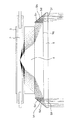
図1には、上記図3に対応する最集光状態、すなわち導光部材4と光学部材5が最も離れた状態を示し、図2には、図4に対応する照射範囲の最も広い状態、すなわち導光部材4と光学部材5とが最も接近した状態を示している。これら図において、各部の符号は上記説明と一致しており、左右方向の特性を説明するための代表光束も合わせて示している。
【0061】
まず、図1に示す状態について説明する。図示のように、光学部材5の左右の射出面には、フレネルレンズ等の集光を行わせるための屈折面が形成されていない。この理由は、放電発光管2の有効アーク長に対して光学部材5の左右の開口部の幅が狭く、かつ接近しているためである。つまり、このように光源から最も遠い光学部材5の射出面側でも十分な距離がとれない場合には、中央部付近にどのような集光面を形成しても各点から光源を見込む角度が大き過ぎて集光させることが困難だからである。
【0062】
例えば、この中央部付近にフレネルレンズを形成したとしても、放電発光管2の中心部付近から射出した光束に関しては集光作用を持たせることができるが、放電発光管2の周辺部から射出した光束に関しては、逆に屈折によって照射範囲が広がったり、また全反射による予想外の反射による光量ロスが生じたり、さらにはフレネルレンズのエッジ部での屈折による光量ロスが生じる可能性が高く、必ずしも好ましい形態ではない。このような理由から、本実施形態では、光学部材5の射出面側には左右方向の集光作用は持たせていない。
【0063】
一方、光学部材5の光源側の周辺部には、入射面5e,5e’と、全反射面5d,5d’と、射出面5f,5f’を有する、左右方向のみについて集光作用を持つプリズム部5h,5h’が形成されている。このように周辺部のみプリズム部5h,5h’を形成している理由は、周辺部からの光源を見込む角度が中央部に比べて狭く、方向もある程度限定できるためであり、光束の方向をある程度制御可能な領域になっているためである。
【0064】
そこで、図1に示す最集光状態を達成できるように、プリズム部5h,5h’の各面の形状を規定し、最適化したのが本実施形態である。図示のように、本実施形態では、光源の左右中心部付近から射出した光束のうち、このプリズム部5h,5h’に入射する光束を射出光軸に対して平行になるように全反射制御している。
【0065】
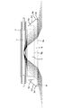
次に、図2を用いて左右方向の照射範囲を広げた状態について説明する。なお、同図では、図1と比較して説明するため、光源の同一点から同一方向に射出した光束の状態も同時に示している。
【0066】
上記説明のように、光学部材5の射出面側には、左右方向の光束を集光させるための特別の屈折面や反射面を形成していない。このため、平面入射部5gから入射した光束成分は、左右方向の照射角度を狭めず均一でかつ広い範囲の分布となる。
【0067】
さらに詳しく説明すると、図2に示す光源中心部付近から射出した光線の状態から見てもわかるように、導光部材4と光学部材5とを接近させて配置することにより、導光部材4からの射出光を全て光学部材5の平面入射部5gから入射させることができる。このことにより、プリズム部5h,5h’に入射する成分をなくし、照射範囲の広い配光特性を得ることができる。
【0068】
次に、図1および図2に示す状態の照射範囲変化の考え方を、図7を用いて説明する。
【0069】
同図において、横軸には中心からの角度、縦軸にはその角度に対する光量を示している。ここで、Gが図1に対応する集光状態を示し、このときの有効照射範囲は、中心の光量に対して50%になる光量になる角度範囲Aとなる。
【0070】
一方、これに対してHは、図2に対応する照射範囲の広い状態を示し、同様に照射範囲はBとなる。
【0071】
これらの図からわかるように、集光状態を示すGは、周辺部に向けて照射されていた光束の一部を射出光軸中心部付近に集光させることによって、中心部付近の光量を増加させた結果、中心光量の50%で規定される有効照射範囲が相対的に狭くなったものである。
【0072】
このように、導光部材4から射出された光束のうち、射出光軸中心から離れる方向(光学部材5の長手方向両端側に向かう方向)に射出した光束を光学部材5の左右に設けたプリズム部5h,5h’に入射させ、光束の方向を集光方向に変換することによって、中心部付近の光量を大幅に増加させることができると共に、必要照射範囲外への光の照射を減少させて、撮影レンズの長焦点距離に対応した効率良い照明光照射を行うことができる。
【0073】
一方、図1の状態と図2の状態との間の状態に光学配置された場合の照明光束の照射範囲は、導光部材4と光学部材5の相対位置関係によって連続的に変化させることができる。これは、光学部材5に形成されたプリズム部5h,5h’に入射する光束成分の量(全反射面5d,5d’で反射する光束成分の量)に応じて射出光軸中心部付近に向かう光束の量を連続的に変化させることができ、この中心部付近の光束の増減によって、中心部付近の光量の50%の光量値で規定した有効照射範囲を連続的に変化させることができるためである。
【0074】
すなわち、図2の状態から徐々にプリズム部5h,5h’への入射光量を増やすことによって周辺に向かう光束を徐々に射出光軸中心部付近に振り向けて射出させるようにすることができ、この結果、照射範囲を連続的に狭める方向に変化させることができる。
【0075】
なお、本実施形態では、光源中心から射出した光束がプリズム部5h,5h’によって全反射し、射出光軸方向に射出するように各面形状を設定しているが、必ずしもこの形状に限定されるわけではなく、光源の任意の位置、例えば光源中心と周辺との中間の位置の光束が、光学部材5によって射出光軸付近に集まるように形状を規定したり、移動の中間点を考慮して、各ズームポイントで良好な配光特性が得られるような任意の反射面形状を用いてもよい。
【0076】
このように、上記光学系は、図3および図4に示す上下方向に関しての照射範囲の変化と対応する方向、つまり、左右方向に関しての照射範囲を変化させることができる。よって、光学ユニットと光学部材5の射出光軸方向への相対移動という単一動作で、上下および左右の両方向の照射範囲変化を達成できると共に、このための連動機構を必要とせず、また照射角度変化も大きいなど、極めて都合の良い照射範囲可変光学系を構成することができる。
【0077】
また、左右方向周辺部の光路を変更する反射面として全反射面5d,5d’を用いたり、プリズム部5h,5h’を導光部材4の射出面の長手方向両端近傍を覆うような形状としたりしているため、方向変更に伴う光量損失が少なく、効率良く照射範囲変更を行うことができる。
【0078】
さらに、本実施形態の左右方向の照射範囲変更は、上下方向で利用した光制御面を利用しておらず、別個の制御面(全反射面5d,5d’)を利用している。このため、上下および左右方向の照射範囲変更を各々独立して行わせることができ、上下および左右方向のそれぞれにおいて照射範囲の設定自由度が高い。
【0079】
なお、本実施形態では、左右方向の照射範囲を変化させる手段として、光学部材5に一体形成したプリズム部5h,5h’に含まれる反射面を用いた場合について説明したが、このようなプリズム部内の反射面以外でも、光輝アルミ等の反射面を光学部材に一体的に構成したり、別体のプリズム部材を用いたりしてもよい。
【0080】
また、本実施形態では、集光作用部の光源に対する射出方向への移動という手法を用いて照射範囲変更を行っているが、これに限らず、入射光束の射出後の射出方向を大幅に切り換えるような光学部材(例えば、光ファイバーや同一部材内の屈折率変化を持たせたグラディエントインデックス材料)を用いて、入射光束の方向を任意に制御できるような構成を採ることにより、同様の効果を得ることができる。
【0081】
(第2実施形態)
図8から図13には、本発明の第2実施形態である照明装置の光学的構成を示している。本実施形態は、第1実施形態に対して、照射範囲を変更する際の導光部材24と光学部材25の相対移動方向を逆にしたものである。すなわち、導光部材24と光学部材25を離した状態で照射範囲を最も広げ、接近させた状態で照射範囲を最も狭めるように構成した実施形態である。すなわち、図8で必要照射範囲外に向かっていた光束成分を、図9で必要画角の周辺成分として活用し、照射範囲を実質的に広げている。
【0082】
なお、本実施形態において、第1実施形態と共通する構成要素には第1実施形態と同符号を付す。また、本実施形態の照明装置も、第1実施形態にて説明したカメラに搭載されるものである。
【0083】
図10および図11は放電発光管2の中央部付近の縦断面図であり、放電発光管2の中心部付近から射出した照明光束の光線トレース図も合わせて示している。また、図12は、照明光学系の主要部の斜視図である。さらに、図8および図9は、放電発光管2の軸方向の断面図であり、光源中心部付近から射出した代表光線も合わせて示している。
【0084】
本実施形態の照明装置の光学特性を規定する構成要素について、図12を用いて詳しく説明する。
【0085】
同図において、23は放電発光管2から射出した光束のうち光射出方向後方に射出された成分を光射出方向前方に反射させる反射傘であり、その内面は高反射率を有する光輝アルミ等の金属材料により形成されている。なお、この内面に、高反射率の金属蒸着面を形成してもよい。
【0086】
24は、放電発光管2からの射出光束をいくつかの光路領域に分割すると共に、それぞれの領域の光束を射出面から射出させた後に、一定の距離で交差させ一定の広がりの配光特性に変換するための導光部材である。この導光部材24の射出面には、上下方向に関して正の屈折力を持った複数のシリンドリカルレンズ24dが上下方向に配列形成されている。
【0087】
25は、導光部材24から射出した光束を入射させ、必要とされる所定の配光特性に変換するための光学部材である。この光学部材25の入射面には、上下方向に関して負の屈折力を有する複数のシリンドリカルレンズ25aが上下方向に配列形成されている。
【0088】
また、光学部材25における光源側の左右周辺部には、上下方向に延びて入射光を全反射制御するプリズム部(集光作用部)25b,25b’が形成されている。
【0089】
このような構成において、放電発光管2,反射傘23および導光部材24は不図示の保持ケース等により保持されて一体化され、発光ユニットを構成する。そして、照明装置の外表面に固定された光学部材25に対して上記発光ユニットを適宜移動させることにより、照明光の集光度合を連続的に変化させることができる。なお、導光部材24および光学部材25の材料としては、アクリル樹脂等の透過率の高い光学用樹脂材料やガラス材料が好ましい。
【0090】
本実施形態の照明装置は、カメラの撮影レンズがズームレンズである場合に、その焦点距離に応じて導光部材24と光学部材25との相対位置関係を変化させることによって、上下方向の配光特性を撮影レンズの画角範囲に対応させるようにすると共に、本来有効となる光源が大きすぎて光束の制御がむずかしい左右方向の配光特性も、他の部材を介さずに撮影レンズの画角範囲に対応するように変化させることできる照明装置である。
【0091】
以下、図8から図11を用いて、この照射範囲変更のための最適な光学的形状の設定方法についてさらに詳しく説明する。
【0092】
図10および図11は、本実施形態の照明装置における放電発光管2の径方向の縦断面図であり、上下方向の照射範囲変更の基本的な考え方を示す図である。なお、図中の各部の符号は、図12に対応している。また、図10には、導光部材24と光学部材25とが最も接近した状態を、図11には、導光部材24と光学部材25とが最も離れた状態をそれぞれ示している。また、図10および図11には、同時に放電発光管2の内径中心部より射出した代表光線の軌跡も同時に示している。
【0093】
また、本実施形態は、上下方向の配光特性を均一に保ったまま照射範囲を連続的に変化させることができるとともに、上下方向の開口高さを必要最小限に構成したものである。
【0094】
まず、上記構成の光学系の特徴的な形状を順を追って説明する。反射傘23は、その内面の形状が、放電発光管2とほぼ同心形状の半円筒形状としている。これは、第1実施形態と同様の理由による。
【0095】
一方、反射傘23の上下の周辺部は、導光部材24の後方に回り込むような形態となっているが、これは、以下の理由による。
【0096】
すなわち、光源中心から射出した光束は、図示のように導光部材24の内面の反射面24c,24c’によって理想的な反射を行わせることができるが、図中光源の中心より右側から射出した光束は、特に光源の内径が大きい場合に、反射しきれずに、反射面24c,24c’から射出してしまう成分があり、このような光束を有効に利用するためである。すなわち、反射傘23の形態を図示のように導光部材24の背面まで伸ばし、また、反射面24c,24c’の形状に沿わせることによって、反射面24c,24c’で反射しきれずに反射面24c,24c’から射出した光束を導光部材24内に再入射させることができ、反射後の光束も所定の照射範囲に効率良く集光させることができる。
【0097】
また、導光部材24は、本実施形態では、以下のような形状となるように設定している。
【0098】
まず、上下方向中央領域では、入射面24aに正の屈折力を与えるシリンドリカルレンズが形成され、光源中心から射出した光束は図示のように一度射出光軸と平行になるように変換される。
【0099】
また、上下部の領域では、入射面24b,24b’で屈折した後、その上下方向に位置する全反射面24c,24c’で反射し、こちらも同様に光源中心から射出した光束が射出光軸と平行になるように変換される。
【0100】
こうして光源中心から射出された光束が射出光軸に対して一度平行化された後、図11に示すように射出面24dに形成された複数の正の屈折力を持つシリンドリカルレンズ24dによって、複数の集光領域が形成される。
【0101】
一方、光学部材25の入射面には、導光部材24の射出面に形成した複数のシリンドリカルレンズ24dのパワーをうち消すような負の屈折力を持つ複数のシリンドリカルレンズ25aが形成されている。
【0102】
このように構成することによって、図10に示すように、導光部材24と光学部材25が接近した状態では、各シリンドリカルレンズの屈折力がうち消され、導光部材の入射面24aの屈折、又は入射面24b,24b’での屈折後の反射面24c,24c’での反射による集光状態をそのまま維持させることができる。
【0103】
一方、図11に示すように、導光部材24と光学部材25が最も離れた状態では、配光特性を均一にある一定の範囲に広げることが可能になる。これは、導光部材24のシリンドリカルレンズ24dによって集光された各領域の光束を、光学部材25のシリンドリカルレンズ25aの屈折力の弱い中心部付近を通過させているためであり、このように光学系を構成することでシリンドリカルレンズ25aの影響を受けにくくさせることができる。
【0104】
また、光学系の配置を上記図10の状態と図11の状態と間の状態にすると、導光部材24の移動距離に応じて、上記シリンドリカルレンズ25aの屈折力の影響を連続的に変化させることも可能である。この結果、配光特性も移動距離に応じて変化させることができ、この両者の相対位置を規定することによって、配光特性を連続的に、かつ均一な状態で変化させることが可能になる。
【0105】
このようにして、上下方向の配光特性は、導光部材24と光学部材25の射出光軸方向の相対距離の変化によって連続的に変化させることが可能である。
【0106】
次に、左右方向の配光特性の変化を図8および図9を用いて説明する。これら図は放電発光管2の中心軸を含む横断面図であり、図8は図10に対応する、照射範囲の最も狭い状態、すなわち導光部材24と光学部材25とが最も接近した状態を示し、図9は図11に対応する、照射範囲が最も広い状態、すなわち導光部材24と光学部材25とが最も離れた状態を示している。これら図において、各部の符号は上記説明の構成部材と一致しており、左右方向の特性を説明するための光源中心から射出した代表光束も合わせて示している。
【0107】
図示のように、光学部材25の左右周辺部の射出面は平面で形成されている。このように平面としている理由は、第1実施形態と同様であり、光源からの距離が近くまた長いため、どのような集光面を形成しても各点から光源を見込む角度が大き過ぎて集光させることが困難なためである。
【0108】
一方、光学部材25の光源側の左右周辺部には、左右方向にのみ集光作用を持つプリズム部25b,25b’が形成されている。
【0109】
このように左右周辺部のみプリズム部25b,25b’を形成している理由は、周辺部からの光源を見込む角度が中央部に比べて狭く、かつ方向もある程度限定でき、光束の方向をある程度制御可能なためである。
【0110】
光線トレース図からもわかるように、図8に示す状態では、光源中心から射出した光束に対して集光効果を持たすことができない。一方、図9に示す状態では、図8に示す光源中心部から射出された光線と同一の光線が、プリズム部25b,25b’に入射することによって、ある一定の射出方向に変換される。
【0111】
この状態をさらに詳しく説明する。プリズム部25b,25b’は、平面で形成された入射面25c,25c’と、非球面形状の全反射面25d,25d’と,平面で形成された射出面25eの左右周辺部分とから構成されている。
【0112】
まず、入射面25c,25c’は、図9の光線トレース図に示すように、入射光量を増やし形状を最小化するために、射出光軸に対して略垂直になるような平面形状となっている。
【0113】
また、全反射面25d,25d’は、射出面25eから射出した後の光束が、全てある一定の角度、図中のθとなるような図面垂直方向に伸びる非球面形状となっている。
【0114】
プリズム部25b,25b’を上記形状とすることで、左右方向の照射角度を一定量広げることが可能になる。このこと関して、図13を用いて、図8および図9に示す状態の照射角度変化の考え方を説明する。
【0115】
図13において、横軸には中心からの角度、縦軸にはその角度に対する光量を示している。ここで、Iが図8に対応する状態を示し、このときの有効照射範囲は、中心の光量に対して50%になる光量になる角度範囲Bとなる。この状態は、左右の周辺部の光束を有効に利用しきれない状態である。
【0116】
一方、これに対してJは、図9に対応する照射範囲の広い場合を示し、このときの照射角度はCとなる。この図からもわかるように、左右方向の照射範囲を広げるために、Iは左右周辺部に照射されていた光束の一部を必要照射範囲の周辺部に振り向けて、周辺部の光量が中心光量に対して50%程度になるようにすることにより照射範囲を広げるようにした状態である。
【0117】
このように、プリズム部25b,25b’で制御可能な光束は、導光部材24と光学部材25の相対移動に伴う、わずかな隙間から射出する光線の射出方向を(この光線は絶対量的には少ない光束ではあるが)かなり正確に制御することが可能なため、このような中心光量に対して50%に対応する狭い領域の角度成分のみを上昇させる照明光学系に対して、有効な照射範囲変更の方法として利用することができる。
【0118】
以上のような方法により、必要照射範囲外への光の照射を減少させて、撮影レンズの焦点距離に対応した効率良い照射範囲調整を行うことができる。
【0119】
なお、本実施形態では、プリズム部25b,25b’によって、光源中心から射出した光束が、すべて一定角度θに変換されるように構成したが、必ずしも一定角度になるように制御する必要はない。例えば、プリズム部を利用して、必要照射範囲の周辺部付近の光量を増すような任意の反射面形状であってもよく、反射面形状を最適化することによって同様の効果を得ることができる。
【0120】
また、本実施形態では、光源として、直管タイプの放電発光管を用いる場合について説明したが、光源としてはこのようなタイプの放電発光管に限定されるわけではなく、点光源と見なせないある程度長い有効発光部を有するような光源(例えば、冷陰極管)を用いてもよい。
【0121】
(第3実施形態)
図14および図15には、本発明の第3実施形態である照明装置の光学的構成を示している。本実施形態は、第1実施形態に対して、光学部材35の一部を変形させた例であり、特に、光学部材35の左右周辺部に設けたプリズム部を複数に分割してプリズム列としたことを特徴としている。
【0122】
なお、本実施形態において、第1実施形態と共通する構成要素には第1実施形態と同符号を付す。また、本実施形態の照明装置も、第1実施形態にて説明したカメラに搭載されるものである。
【0123】
また、上下方向、すなわち放電発光管2の径方向の照射範囲変更の様子は図3および図4と同様である。
【0124】
図14および図15において、34は放電発光管2からの射出光束を入射させ、一定の広がりの配光特性に変換するための導光部材である。また、35は導光部材34からの射出光を入射させ、必要とされる所定の配光特性に変換するための光学部材である。この光学部材35の射出面の左右両側には、複数のプリズム部35b,35c,35b’,35c’からなるプリズム列が形成されている。
【0125】
ここで、図14には、導光部材34と光学部材35とを最も離して照射範囲を最も狭めた状態を、図15には、導光部材34と光学部材35とを最も接近させて照射範囲を最も広げた状態をそれぞれ示しており、これら図には、放電発光管2の中心部付近から射出させた代表光束の光線トレースも合わせて示している。なお、放電発光管2および反射傘3は、第1実施形態と同様のものである。
【0126】
また、図14の状態での上下方向の集光状態は、第1実施形態の図3に示すものと同様である。図15の状態での上下方向の集光状態は、第1実施形態の図4に示すものと同様である。
【0127】
次に、本実施形態の照明装置の動作について説明する。図14の状態において、放電発光管2の中心部付近から射出した光束のうち、光学部材35の両端の光源側に形成されたプリズム列35b,35b’,35c,35c’に入射した光束は、これらプリズム列35b,35b’,35c,35c’の全反射面によって射出方向を変換される。これにより、射出光軸付近に向かう光束成分が増加する。したがって、この面を平面で構成する場合に比べて大幅に中心光量を増加させることができる。
【0128】
本実施形態では、導光部材34から射出された照明光束に対し、集光のための屈折力を、光学部材35の左右両端の光源側に形成された図面垂直方向に伸びる複数のプリズム列での反射作用により与えている。このように、プリズム部を複数に分割しても、第1実施形態の図1の状態とほぼ同等の集光効果を得ることができる。
【0129】
次に、図15の状態において、導光部材34から射出された光束は、すぐに光学部材35に入射し、左右周辺部に形成されたプリズム部35b,35b’,35c,35c’には入射しない。このため、図14に示した光線と同一の射出点、射出方向の条件で放電発光管2から射出した光束は集光作用を受けない。このため、全体として広がった配光特性を得ることができる。
【0130】
なお、本実施形態では、光学部材35に集光作用を持たせる反射部として、左右2列ずつのプリズム部を形成しているが、必ずしも2列に限定されるわけではなく、3列以上のプリズム列としてもよい。また、形状も左右の開口面積を広げてプリズムの突出量を減らし、板形状に近づけるような構成をとってもよい。
【0131】
さらに、プリズム部による照射方向の制御方法として、光源中心から射出させた光束を、導光部材34と光学部材35間の間隔が最も離れた状態で射出光軸に対して平行になるように設定しているが、必ずしもこのように設定する必要はない。すなわち、導光部材と光学部材が離れた状態で、左右周辺部に逃げる光束を取り込み、射出光軸の方向に近づけるような効果を持ったプリズム部であれば、本実施形態と同様の効果が得られる。
【0132】
また、本実施形態では、光学部材35の射出面に形成したプリズム列として図面垂直方向に伸びる形状としているが、必ずしもこの方向に限定されるわけではない。例えば、ある一定角度傾いたプリズム列や同心の輪帯状のプリズム列を用いてもよい。
【0133】
(第4実施形態)
図16および図17には、本発明の第4実施形態である照明装置の光学的構成を示している。本実施形態は、第1実施形態に対して、光学部材45の一部形状を変形させた、上記第3実施形態とは異なる変形例であり、特に、光学部材45の左右周辺部に、光学部材45とは別体の反射部材(反射板46)を一体的に設けたこと特徴としている。
【0134】
なお、本実施形態において、第1実施形態と共通する構成要素には第1実施形態と同符号を付す。また、本実施形態の照明装置も、第1実施形態にて説明したカメラに搭載されるものである。
【0135】
また、上下方向、すなわち放電発光管2の径方向の照射範囲変更の様子は図3および図4と同様である。
【0136】
図16および図17において 44は放電発光管2からの射出光束を入射させ、一定の広がりの配光特性に変換するための導光部材である。また、45は導光部材44からの射出光を入射させ、必要とされる所定の配光特性に変換するための光学部材である。また、46,46’は光学部材45に一体的に取り付けられた反射板である。
【0137】
ここで、図16には、導光部材44と光学部材45とを最も離して照射範囲を最も狭めた状態を、図17には、導光部材44と光学部材45とを最も接近させて照射範囲を最も広げた状態をそれぞれ示しており、これら図には、放電発光管2の中心部付近から射出した代表光線の光線トレースも合わせて示している。なお、放電発光管2および反射傘3は、第1実施形態と同様のものである。
【0138】
また、図16の状態での上下方向の集光状態は、第1実施形態の図3に示すものと同様である。図17の状態での上下方向の集光状態は、第1実施形態の図4に示すものと同様である。
【0139】
次に、本実施形態の照明装置の動作について説明する。図16において、放電発光管2の中心部付近から射出した光束のうち、光学部材45の両端における光源側に取り付けられた反射板46,46’に入射した光束は、これら反射板46,46’に非球面曲面として形成された反射面によって射出方向を変換される。これにより、射出光軸付近に向かう光束成分が増加する。したがって、この面を平面で構成する場合に比べて大幅に中心光量を増加させることができる。
【0140】
本実施形態では、導光部材44から射出された照明光束に対し、集光作用を、光学部材45の左右両端の光源側に設けられた図面垂直方向に伸びる反射板46,46’の反射作用により与えている。このように、反射部材を用いても、第1実施形態の図1の状態とほぼ同等の集光効果を得ることができる。
【0141】
次に、図17の状態において、導光部材44から射出された光束は、すぐに光学部材45に入射し、左右周辺部に設けられた反射板46,46’には入射しない。このため、図16に示した光線と同一の射出点、射出方向の条件で放電発光管2から射出した光束は集光作用を受けない。このため、全体として広がった配光特性を得ることができる。
【0142】
なお、本実施形態では、光学部材に集光作用を持たせる反射部材として、図面垂直方向に伸びる非球面反射曲面を形成し、光源中心から射出した光束を射出光軸と平行になるように変換しているが、反射部材の形状は必ずしもこの形状に限定されない。すなわち、導光部材と光学部材とが離れた状態で、左右周辺部に逃げる光束を取り込み、射出光軸の方向に近づけるような効果を持った反射部材であれば、本実施形態と同様の効果が得られる。
【0143】
本実施形態のように、導光部材44と光学部材45との間から側方に照射される光束を取り込み照射方向を変換させる部材として反射部材を用いることは、導光部材44から直接、光学部材45の左右周辺部に当たる光束を制御できず、一部光線が有効利用できないことと、反射部材そのものの反射率による光量低下が起こり得るというだけで、他は上記各実施形態とほぼ同等であり、有効に利用できなかった光束を取り込み、効率の良い配光特性制御が可能となる。
【0144】
また、上記実施形態では、光学部材45に固定した反射板46,46’の形状を図面垂直方向に伸びる形状としているが、必ずしもこの方向に限定されるわけではなく、平面または球面、回転楕円体等の形状としてもよく、この形状を最適化させることで、効率の良い照射範囲変更が可能となる。
【0145】
なお、以上説明した各実施形態では、照明装置をフィルム使用カメラに搭載した場合について説明したが、本発明の照明装置は、デジタルスチルカメラ、ビデオカメラ等の各種撮影装置に搭載することができる。また、本発明は、上記各実施形態のような撮影装置内蔵タイプの照明装置だけではなく、外付けタイプの照明装置にも適用することができる。さらに、本発明は、撮影時の照明装置としてだけでなく、ストロボ光を用いた光通信用の照明装置にも適用することが可能である。
【0146】
【発明の効果】
以上説明したように、本発明によれば、発光ユニットと光学部材とを相対移動させて、発光ユニットから射出される照明光束のうち光学部材の少なくとも一方の端方向に向かって上記反射部にて反射する光束成分を増減させ、照明光束の照射範囲を変更するようにしているので、簡単かつコンパクトな構成で、光源ユニットの長手方向の照射範囲制御に適した照明装置を実現することができる。したがって、この照明装置を搭載する撮影装置についても、小型・軽量化を図るとともに優れた撮影性能を有することができる。
【0147】
また、上記反射部で反射した光束成分を増減させて照射範囲を変更させる構成であるため、上記増減を連続的に行って照射範囲を連続的に変更することも容易に行うことができる。
【0148】
さらに、上記反射部を発光ユニットにおける射出面の端部近傍を覆うように設けたり、上記反射部に全反射面を用いることにより、光源ユニットからのエネルギを高い効率で利用可能となる。
【0149】
しかも、上記光学部材に、上記反射部で反射して射出した光束成分を増減させて変更する照射範囲の変更方向(例えば、光源ユニットの長手方向)とは異なる方向(例えば、長手方向に直交する方向)における照明光束の照射範囲を、発光ユニットとこの光学部材とを相対移動させることにより変更するための光学作用部を設けるようにすれば、上記両方向の照射範囲変更を連動させるための機構等が不要な簡単かつコンパクトな構成で、上記両方向に関する照射範囲を適切に制御可能な照明装置を実現することができる。
【0150】
なお、上記反射部を上記光学作用部とは別個に設けるようにすれば、上記両方向のそれぞれにおける照射範囲変更を互いに独立に行わせることができ、いずれの方向についても照射範囲の設定自由度を高くすることができる。
【図面の簡単な説明】
【図1】本発明の第1実施形態である照明装置(照射範囲小)の放電管軸方向の横断面図。
【図2】上記第1実施形態である照明装置(照射範囲大)の放電管軸方向の横断面図。
【図3】上記第1実施形態である照明装置(照射範囲小)の放電管径方向の縦断面図。
【図4】上記第1実施形態である照明装置(照射範囲大)の放電管径方向の縦断面図。
【図5】上記第1実施形態である照明装置の光学系の要部を示す斜視図。
【図6】上記第1実施形態の照明装置を適用したカメラの斜視図。
【図7】上記第1実施形態の照明装置の照射範囲を説明するための配光特性図。
【図8】本発明の第2実施形態である照明装置(照射範囲小)の放電管軸方向の横断面図。
【図9】上記第2実施形態である照明装置(照射範囲大)の放電管軸方向の横断面図。
【図10】上記第2実施形態である照明装置(照射範囲小)の放電管径方向の縦断面図。
【図11】上記第2実施形態である照明装置(照射範囲大)の放電管径方向の縦断面図。
【図12】上記第2実施形態である照明装置の光学系の要部を示す斜視図。
【図13】上記第2実施形態の照明装置の照射範囲を説明するための配光特性図。
【図14】本発明の第3実施形態である照明装置(照射範囲小)の放電管軸方向の横断面図。
【図15】上記第3実施形態である照明装置(照射範囲大)の放電管軸方向の横断面図。
【図16】本発明の第4実施形態である照明装置(照射範囲小)の放電管軸方向の横断面図。
【図17】上記第4実施形態である照明装置(照射範囲大)の放電管軸方向の横断面図。
【符号の説明】
1 照明装置
2 放電発光管
3,23 反射傘。
4,24,34,44 導光部材
5,25,35,45 光学部材
5h,5h’,25b,25b’,35b,35b’,35c,35c’ プリズム部
5d,5d’,25d,25d’ 全反射面
46,46’ 反射板[0001]
BACKGROUND OF THE INVENTION
The present invention relates to an illuminating device capable of changing an irradiation range and a photographing device including the same.
[0002]
[Prior art]
Conventionally, various proposals have been made on an illumination device used in a photographing apparatus such as a camera in order to efficiently collect a light beam emitted from a light source in various directions within a required irradiation angle of view.
[0003]
In particular, in recent years, instead of the Fresnel lens that is conventionally arranged in front of the light source, an optical member using total reflection such as a prism or a light guide is arranged, thereby improving the light collection efficiency and reducing the size. ing.
[0004]
By the way, in recent years, in an imaging apparatus such as a camera, the apparatus itself has been reduced in size and weight, while the imaging lens tends to have a high magnification zoom. In general, due to the downsizing and high magnification of such an imaging apparatus, the open F number value of the imaging lens tends to gradually increase. If an image is taken without using an auxiliary light source, it is unexpected due to camera shake or subject blur. It may become a blurred photo or a failed photo due to underexposure. In order to cope with this situation, the photographing apparatus often incorporates an illumination device as an auxiliary light source.
[0005]
However, under these circumstances, the usage frequency of lighting devices has increased significantly. As well as Since the amount of light emission required for one shooting is increased, the irradiation range is generally fixed corresponding to the wide state, and the unnecessary range is illuminated in the tele state, resulting in a large energy loss. A lighting device with a fixed irradiation range cannot adequately cope with it.
[0006]
Against this background, various illumination devices with variable illumination ranges have been proposed as illumination devices that illuminate only the range corresponding to the field of view and save power. In particular, several lighting devices that have improved luminous efficiency using total reflection have been proposed.
[0007]
For example, in the illuminating device proposed by the present applicant in Japanese Patent Laid-Open No. 4-138439, after the light beam emitted mainly from the light source to the side of the emission optical axis is incident on the optical member on the front surface of the illuminating device, It consists of two upper and lower surfaces that are totally reflected and focused in a certain direction, and a surface that has a positive refractive power formed on the front side separately from this, and after focusing by each surface, from the same exit surface With respect to the condensing optical system to be emitted toward the object side, the positional relationship between the optical prism and the light source is relatively changed to switch between reflection and transmission on the total reflection surface, thereby changing the irradiation range.
[0008]
Further, in the illumination device proposed in the above Japanese Patent Laid-Open No. 8-262538, the optical prism is divided into a plurality of parts, and the irradiation range is changed by rotating the optical prisms arranged vertically.
[0009]
[Problems to be solved by the invention]
However, in the illuminating device proposed in the above publication, light condensing and diffusing in the radial direction of the cylindrical discharge arc tube that is relatively easy to control light, that is, in the direction (vertical direction) perpendicular to the longitudinal direction (horizontal direction) of the light source It is control, and the light-diffusion control of the longitudinal direction of the light source is not performed. For this reason, even if it is called irradiation range control, it is irradiation range control only in the up-down direction, and ideal irradiation range control is not necessarily performed.
[0010]
For this reason, in the present invention, an illuminating device that can use the energy from the light source with high efficiency while miniaturizing the entire device, and that is suitable for simultaneously controlling the irradiation range in the longitudinal direction of the light source and the direction orthogonal thereto. It is intended to provide.
[0011]
[Means for Solving the Problems]
In order to achieve the above object, according to the present invention, there is provided an illuminating device including a translucent optical member that emits an illuminating light beam incident from a light emitting unit, and includes a reflecting portion at at least one end of the optical member. By changing the light emitting unit and the optical member relative to each other, the illumination beam reflected from the reflector is increased or decreased to change the illumination beam irradiation range. I try to let them.
[0012]
That is, by relatively moving the light emitting unit and the optical member, the light beam emitted from the light emitting unit toward the at least one end direction of the optical member is not reflected at all or slightly reflected by the reflecting portion. The illumination range can be changed by emitting light from the optical member or by reflecting a large amount of light at the reflection part, realizing a lighting device suitable for controlling the illumination range in the longitudinal direction of the light source unit with a simple and compact configuration. is doing.
[0013]
Further, since the irradiation range is changed by increasing / decreasing the luminous flux component reflected by the reflecting portion, it is also easy to continuously change the irradiation range by performing the increase / decrease continuously.
[0014]
And the energy from a light source unit can be utilized with high efficiency by providing the said reflection part so that the edge part vicinity of the emission surface in a light emission unit may be covered, or using a total reflection surface for the said reflection part.
[0015]
Moreover, a direction (for example, orthogonal to the longitudinal direction) that is different from the direction of change of the irradiation range (for example, the longitudinal direction of the light source unit) in which the optical member is changed by increasing / decreasing the luminous flux component reflected and emitted from the reflecting portion. direction) In Optical action unit for changing the illumination light beam irradiation range by moving the light emitting unit and the optical member relative to each other The By providing, it is possible to realize an illuminating device that can appropriately control the irradiation range in both directions with a simple and compact configuration that does not require a mechanism for interlocking the irradiation range change in both directions.
[0016]
In addition, by providing the reflection part separately from the optical action part, the irradiation range in each of the two directions can be changed independently of each other. Even It is possible to increase the degree of freedom in setting the irradiation range.
[0017]
DETAILED DESCRIPTION OF THE INVENTION
(First embodiment)
1 to 6 show a lighting apparatus according to the first embodiment of the present invention. 1 and FIG. 2 are transverse cross-sectional views of the main part constituting the optical system of the illumination device, and FIGS. 3 and 4 are vertical cross-sectional views of the main part constituting the optical system of the illumination device. FIG. 5 is a perspective view of only the main optical system of the illumination device, and FIG. 6 is a perspective view of a camera equipped with the illumination device. 1 to 4 also show ray trace diagrams of representative rays emitted from the light source.
[0018]
First, an overall configuration of a camera provided with the illumination device will be described. As shown in FIG. 6, the lighting device 1 is disposed so as to be housed in the upper part of the
[0019]
In the figure, 12 is a lens barrel for holding a photographing lens, 13 is a release button, 14 is a tele direction zooming button, 15 is a wide direction zooming button, 16 is an operation button for switching various modes of the camera,
[0020]
Next, each component relating to the optical characteristics of the illumination device will be described with reference to FIG. In FIG. 5,
[0021]
4 divides the luminous flux emitted from the
[0022]
5 is a translucent light guide member 4 Is a light-transmitting optical member for making a light beam emitted from the light incident and converting it into a required light distribution characteristic, and a plurality of cylindrical lenses having optical refractive power in the vertical direction on the light
[0023]
The
[0024]
In the camera configured as described above, for example, when “strobe auto mode” is set, after the
[0025]
When the central processing unit determines that the lighting device 1 needs to emit light, the central processing unit issues a light emission command, and the
[0026]
In this embodiment, the change of the light distribution characteristic is performed only by relative movement (movement of the light emitting unit) of the light emitting unit (that is, the light guide member 4) and the
[0027]
In the present embodiment, when the photographing lens of the camera is a zoom lens, the relative position in the direction of the irradiation optical axis between the light emitting unit and the
[0028]
Hereinafter, the optimum optical shape setting method for changing the irradiation range will be described in more detail with reference to FIGS.
[0029]
First, the basic principle of changing the irradiation range in the discharge tube radial direction (vertical direction) in the illumination device 1 will be described with reference to FIGS. 3 and 4. 3 and 4 correspond to those in FIG.
[0030]
FIG. 3 shows a state in which the optical unit and the
[0031]
In addition, the lighting device 1 described here can continuously change the irradiation range while keeping the light distribution characteristics in the vertical direction uniform, and has a configuration in which the height of the opening in the vertical direction is minimized. It is.
[0032]
3 and 4 show the inner and outer diameters of the glass tube portion of the
[0033]
First, characteristic portions of the illumination optical system having the above-described configuration will be described in order. The inner surface of the
[0034]
The reason why the shape of the
[0035]
Moreover, the light guide member 4 is formed in the following shapes in this embodiment. First, in the central region in the vertical direction of the light guide member 4, a cylindrical lens that gives positive refractive power to both the
[0036]
In the upper and lower regions, the light beam emitted from the center of the
[0037]
On the other hand, as described above, the
[0038]
Next, each surface shape of the light guide member 4 will be described in more detail. First, in the cylindrical lens formed on the
[0039]
This is because the light beam after being refracted by the
[0040]
Next, the shapes of the incident surfaces 4c and 4c ′ for guiding incident light to the total reflection surfaces 4d and 4d ′ of the light guide member 4 will be described. These surfaces are preferably planes parallel to the optical axis in order to minimize the shape of the light guide member 4. That is, the component of the luminous flux emitted from the light source that travels in a direction different from the emission optical axis is refracted once on this incident surface. The smaller the angle of this surface, the greater the refraction effect. This is because it can be once guided away from the optical axis, and the total length of the optical prism can be kept short.
[0041]
In practice, however, the inclinations of the incident surfaces 4 c and 4 c ′ are substantially determined by the molding conditions of the light guide member 4. The smaller the angle is, the more severe the actual molding conditions are. However, the ideal shape of the maximum angle Φ of this surface is desirably in the following range regardless of whether the incident surface is flat or curved.
[0042]
0 ≦ Φ <2 ° (1)
The above range is a setting value that seems to be difficult at first glance, but it is a sufficiently possible value because the distance between the incident surfaces 4c and 4c ′ is short and the surface shape is a smooth surface. By defining the inclinations of the incident surfaces 4c and 4c ′ as described above, the opening area in the vertical direction can be minimized and the efficiency can be reduced.
[0043]
Next, the shapes of the reflecting
[0044]
As the shape of this part, it is desirable to condense an angle component close to the exit optical axis at one point as in the case of the entrance /
[0045]
Therefore, in the present embodiment, the shapes of the reflecting
[0046]
On the other hand, of the light emitted from the
[0047]
Next, the shape of the
[0048]
Each of these lenses is the sum of the central region that is collected by the cylindrical lens having the positive refractive power described in the above-described light guide member 4 and the upper and lower two regions that perform pseudo light collection by total reflection. The light emitted from the three regions has such a shape that the degree of condensing can be changed at a certain ratio, and the three regions are arranged in the same manner depending on the distance between the light guide member 4 and the
[0049]
Further, as shown in FIG. 3, the central lens among the above lenses is not such that the light beam emitted from the point P is refracted by the
[0050]
That is, the upper and lower lens surfaces are separated from the central portion of the lens so that the light beam after passing through the exit surface becomes a component parallel to the exit optical axis when the light guide member 4 and the
[0051]
More specifically, of the total reflected light component, the component parallel to the emission optical axis near the center is the boundary, the outer part is a lens surface with a weak refractive power, and the inner region is a strong refractive power. It consists of a lens surface.
[0052]
By configuring in this way, it is possible to achieve the most concentrated state in the vertical direction as shown in FIG. 3 in a state where the distance between the light guide member 4 and the
[0053]
On the other hand, as a state for obtaining the light distribution characteristic that spreads most in the vertical direction, a state in which the distance between the light guide member 4 and the
[0054]
As described above, the light condensing region of the light guide member 4 is made substantially coincident with the region that is hardly affected by the lens refractive power in the vicinity of the optical axis center of each lens on the exit side of the
[0055]
That is, by arranging the optical system as in the above configuration and appropriately setting the predetermined condensing state by the light guide member 4 and the thickness of the
[0056]
In the present embodiment, the lens surface of the
[0057]
If the arrangement of the optical system is between the state shown in FIG. 3 and the state shown in FIG. 4, the influence of the refractive power of the
[0058]
In this way, the light distribution characteristics in the vertical direction can be continuously changed by changing the relative positions of the light guide member 4 and the
[0059]
Next, changes in the light distribution characteristics in the axial direction, that is, the longitudinal direction of the
[0060]
FIG. 1 shows the most condensed state corresponding to FIG. 3 above, that is, the state where the light guide member 4 and the
[0061]
First, the state shown in FIG. 1 will be described. As shown in the drawing, the left and right exit surfaces of the
[0062]
For example, even if a Fresnel lens is formed in the vicinity of the central portion, the light flux emitted from the vicinity of the central portion of the
[0063]
On the other hand, the light source side peripheral portion of the
[0064]
Therefore, in this embodiment, the shape of each surface of the
[0065]
Next, the state where the irradiation range in the left-right direction is expanded will be described with reference to FIG. In the figure, for the purpose of comparison with FIG. 1, the state of the light beam emitted in the same direction from the same point of the light source is also shown.
[0066]
As described above, no special refracting surface or reflecting surface for converging the light beam in the left-right direction is formed on the exit surface side of the
[0067]
More specifically, as can be seen from the state of the light beam emitted from the vicinity of the light source center shown in FIG. All of the emitted light can be incident from the
[0068]
Next, the concept of irradiation range change in the state shown in FIGS. 1 and 2 will be described with reference to FIG.
[0069]
In the figure, the horizontal axis indicates the angle from the center, and the vertical axis indicates the light quantity with respect to the angle. Here, G shows the light collection state corresponding to FIG. 1, and the effective irradiation range at this time is an angle range A in which the light amount becomes 50% with respect to the central light amount.
[0070]
On the other hand, H indicates a wide irradiation range corresponding to FIG.
[0071]
As can be seen from these figures, G, which indicates the condensing state, increases the amount of light in the vicinity of the central portion by condensing a portion of the light beam irradiated toward the peripheral portion near the central portion of the exit optical axis. As a result, the effective irradiation range defined by 50% of the central light quantity becomes relatively narrow.
[0072]
In this way, among the light beams emitted from the light guide member 4, the prisms provided on the left and right sides of the
[0073]
On the other hand, the irradiation range of the illumination light beam when optically arranged between the state of FIG. 1 and the state of FIG. 2 can be continuously changed according to the relative positional relationship between the light guide member 4 and the
[0074]
That is, by gradually increasing the amount of light incident on the
[0075]
In the present embodiment, the shape of each surface is set so that the light beam emitted from the center of the light source is totally reflected by the
[0076]
Thus, the optical system has a direction corresponding to the change in the irradiation range with respect to the vertical direction shown in FIGS. That is, The irradiation range in the left-right direction can be changed. Therefore In a single operation of relative movement of the optical unit and the
[0077]
Further, the total reflection surfaces 5d and 5d ′ are used as the reflection surfaces for changing the optical path in the left and right direction peripheral portions, or the
[0078]
Further, the change of the irradiation range in the left-right direction of the present embodiment does not use the light control surface used in the up-down direction, but uses separate control surfaces (
[0079]
In the present embodiment, the case where the reflecting surface included in the
[0080]
In the present embodiment, the irradiation range is changed using a method of moving the condensing operation unit in the emission direction with respect to the light source. However, the present invention is not limited to this, and the emission direction after emission of the incident light beam is significantly switched. The same effect can be obtained by adopting a configuration in which the direction of the incident light beam can be arbitrarily controlled by using such an optical member (for example, an optical fiber or a gradient index material having a refractive index change in the same member). be able to.
[0081]
(Second Embodiment)
8 to 13 show an optical configuration of a lighting apparatus according to the second embodiment of the present invention. In the present embodiment, the relative movement directions of the
[0082]
In the present embodiment, components common to the first embodiment are denoted by the same reference numerals as in the first embodiment. The illumination device of this embodiment is also mounted on the camera described in the first embodiment.
[0083]
10 and 11 are longitudinal sectional views of the vicinity of the center portion of the
[0084]
The components that define the optical characteristics of the illumination device of this embodiment will be described in detail with reference to FIG.
[0085]
In the figure,
[0086]
24 divides the luminous flux emitted from the
[0087]
[0088]
In addition, prism portions (condensing action portions) 25b and 25b ′ that extend in the vertical direction and control total reflection of incident light are formed on the left and right peripheral portions of the
[0089]
In such a configuration, the
[0090]
The illumination device according to the present embodiment distributes light in the vertical direction by changing the relative positional relationship between the
[0091]
Hereinafter, an optimal optical shape setting method for changing the irradiation range will be described in more detail with reference to FIGS.
[0092]
FIG. 10 and FIG. 11 are longitudinal sectional views in the radial direction of the
[0093]
Further, in the present embodiment, the irradiation range can be continuously changed while maintaining the light distribution characteristics in the vertical direction uniformly, and the opening height in the vertical direction is configured to be the minimum necessary.
[0094]
First, the characteristic shape of the optical system configured as described above will be described in order. The
[0095]
On the other hand, the upper and lower peripheral portions of the
[0096]
That is, the light beam emitted from the center of the light source can be ideally reflected by the reflecting
[0097]
In the present embodiment, the
[0098]
First, in the central region in the vertical direction, a cylindrical lens that gives positive refractive power to the
[0099]
In the upper and lower regions, after being refracted by the incident surfaces 24b and 24b ′, the light is reflected by the total reflection surfaces 24c and 24c ′ positioned in the vertical direction. Is converted to be parallel.
[0100]
After the light beam emitted from the center of the light source is once made parallel to the emission optical axis, a plurality of
[0101]
On the other hand, on the incident surface of the
[0102]
With this configuration, as shown in FIG. 10, in the state where the
[0103]
On the other hand, as shown in FIG. 11, in the state where the
[0104]
Further, the arrangement of the optical system is shown in the state of FIG. 11 In this state, the influence of the refractive power of the
[0105]
In this way, the light distribution characteristic in the vertical direction can be continuously changed by a change in the relative distance between the
[0106]
Next, changes in the light distribution characteristics in the left-right direction will be described with reference to FIGS. These drawings are cross-sectional views including the central axis of the
[0107]
As shown in the drawing, the exit surfaces of the left and right peripheral portions of the
[0108]
On the other hand,
[0109]
The reason why the
[0110]
As can be seen from the ray trace diagram, in the state shown in FIG. 8, it is not possible to have a condensing effect on the light beam emitted from the center of the light source. On the other hand, in the state shown in FIG. 9, the same light ray emitted from the light source central portion shown in FIG. 8 is incident on the
[0111]
This state will be described in more detail. The
[0112]
First, as shown in the ray trace diagram of FIG. 9, the incident surfaces 25c and 25c ′ have a planar shape that is substantially perpendicular to the emission optical axis in order to increase the amount of incident light and minimize the shape. Yes.
[0113]
Further, the total reflection surfaces 25d and 25d ′ have aspherical shapes in which the light fluxes emitted from the
[0114]
By making the
[0115]
In FIG. 13, the horizontal axis indicates the angle from the center, and the vertical axis indicates the amount of light with respect to that angle. Here, I indicates a state corresponding to FIG. 8, and the effective irradiation range at this time is an angle range B in which the light amount becomes 50% with respect to the central light amount. This state is a state where the light beams in the left and right peripheral portions cannot be used effectively.
[0116]
On the other hand, J indicates the case where the irradiation range corresponding to FIG. 9 is wide, and the irradiation angle at this time is C. As can be seen from this figure, in order to widen the irradiation range in the left-right direction, I directs a part of the light beam irradiated to the left and right peripheral parts to the peripheral part of the necessary irradiation range, and the light quantity in the peripheral part becomes the central light quantity. In this state, the irradiation range is widened by setting it to about 50%.
[0117]
As described above, the light beam that can be controlled by the
[0118]
By the method as described above, the irradiation of light outside the necessary irradiation range can be reduced, and the effective irradiation range adjustment corresponding to the focal length of the photographing lens can be performed.
[0119]
In the present embodiment, the light beams emitted from the center of the light source are all converted to the constant angle θ by the
[0120]
In this embodiment, the case where a straight tube type discharge arc tube is used as the light source has been described. However, the light source is not limited to such a type of discharge arc tube, and cannot be regarded as a point light source. A light source (for example, a cold cathode tube) having an effective light emitting portion that is long to some extent may be used.
[0121]
(Third embodiment)
FIG. 14 and FIG. 15 show the optical configuration of the illumination device according to the third embodiment of the present invention. The present embodiment is an example in which a part of the
[0122]
In the present embodiment, components common to the first embodiment are denoted by the same reference numerals as in the first embodiment. The illumination device of this embodiment is also mounted on the camera described in the first embodiment.
[0123]
The state of changing the irradiation range in the vertical direction, that is, in the radial direction of the
[0124]
In FIGS. 14 and 15,
[0125]
Here, FIG. 14 shows a state in which the
[0126]
Further, the light converging state in the vertical direction in the state of FIG. 14 is the same as that shown in FIG. 3 of the first embodiment. The light condensing state in the vertical direction in the state of FIG. 15 is the same as that shown in FIG. 4 of the first embodiment.
[0127]
Next, operation | movement of the illuminating device of this embodiment is demonstrated. In the state of FIG. 14, among the light beams emitted from the vicinity of the central portion of the
[0128]
In the present embodiment, the refracting power for condensing the illumination light beam emitted from the
[0129]
Next, in the state of FIG. 15, the light beam emitted from the
[0130]
In the present embodiment, the right and left two-row prism portions are formed as the reflecting portions for concentrating the
[0131]
Further, as a method of controlling the irradiation direction by the prism unit, the light beam emitted from the center of the light source is set so as to be parallel to the emission optical axis in the state where the distance between the
[0132]
In this embodiment, the prism array formed on the exit surface of the
[0133]
(Fourth embodiment)
16 and 17 show an optical configuration of an illumination apparatus according to the fourth embodiment of the present invention. This embodiment is a modified example different from the third embodiment in which a part of the
[0134]
In the present embodiment, components common to the first embodiment are denoted by the same reference numerals as in the first embodiment. The illumination device of this embodiment is also mounted on the camera described in the first embodiment.
[0135]
The state of changing the irradiation range in the vertical direction, that is, in the radial direction of the
[0136]
In FIG. 16 and FIG. 17,
[0137]
Here, FIG. 16 shows the state in which the
[0138]
Further, the light converging state in the vertical direction in the state of FIG. 16 is the same as that shown in FIG. 3 of the first embodiment. The light condensing state in the vertical direction in the state of FIG. 17 is the same as that shown in FIG. 4 of the first embodiment.
[0139]
Next, operation | movement of the illuminating device of this embodiment is demonstrated. In FIG. 16, among the light beams emitted from the vicinity of the central portion of the
[0140]
In the present embodiment, a condensing function is applied to the illumination light beam emitted from the
[0141]
Next, in the state of FIG. 17, the light beam emitted from the
[0142]
In this embodiment, an aspherical reflection curved surface extending in the vertical direction of the drawing is formed as a reflecting member for condensing the optical member, and the light beam emitted from the center of the light source is converted to be parallel to the emission optical axis. However, the shape of the reflecting member is not necessarily limited to this shape. That is, as long as the reflecting member has an effect of taking in the light flux escaping to the left and right peripheral parts and bringing it closer to the direction of the exit optical axis in a state where the light guide member and the optical member are separated from each other, the same effect as the present embodiment Is obtained.
[0143]
As in the present embodiment, the
[0144]
Moreover, in the said embodiment, although the shape of
[0145]
In each of the embodiments described above, the case where the lighting device is mounted on a film-use camera has been described. However, the lighting device of the present invention can be mounted on various photographing devices such as a digital still camera and a video camera. In addition, the present invention can be applied not only to an imaging device built-in type lighting device as in each of the above embodiments, but also to an external type lighting device. Furthermore, the present invention can be applied not only to an illumination device at the time of photographing but also to an illumination device for optical communication using strobe light.
[0146]
【The invention's effect】
As described above, according to the present invention, the light emitting unit and the optical member are moved relative to each other, and the reflecting portion is directed toward at least one end of the optical member of the illumination light beam emitted from the light emitting unit. Since the light flux component to be reflected is increased or decreased to change the irradiation range of the illumination light beam, an illumination device suitable for controlling the irradiation range in the longitudinal direction of the light source unit can be realized with a simple and compact configuration. Therefore, an imaging device equipped with this illumination device can also be reduced in size and weight and have excellent imaging performance.
[0147]
In addition, since the irradiation range is changed by increasing / decreasing the luminous flux component reflected by the reflecting portion, the irradiation range can be easily changed by continuously increasing / decreasing the above-described increase / decrease.
[0148]
Furthermore, the energy from the light source unit can be used with high efficiency by providing the reflection portion so as to cover the vicinity of the end of the emission surface of the light emitting unit, or by using the total reflection surface for the reflection portion.
[0149]
Moreover, a direction (for example, orthogonal to the longitudinal direction) that is different from the direction of change of the irradiation range (for example, the longitudinal direction of the light source unit) in which the optical member is changed by increasing / decreasing the luminous flux component reflected and emitted from the reflecting portion. direction) In Optical action unit for changing the illumination light beam irradiation range by moving the light emitting unit and the optical member relative to each other The If provided, a lighting device capable of appropriately controlling the irradiation range in both directions can be realized with a simple and compact configuration that does not require a mechanism for linking the irradiation range change in both directions.
[0150]
In addition, if the reflection part is provided separately from the optical action part, the irradiation range in each of the two directions can be changed independently of each other. Even The degree of freedom in setting the irradiation range can be increased.
[Brief description of the drawings]
FIG. 1 is a cross-sectional view in the discharge tube axial direction of a lighting device (small irradiation range) according to a first embodiment of the present invention.
FIG. 2 is a cross-sectional view in the discharge tube axial direction of the illumination device (large irradiation range) according to the first embodiment.
FIG. 3 is a longitudinal sectional view in the discharge tube radial direction of the illumination device (small irradiation range) according to the first embodiment.
FIG. 4 is a longitudinal sectional view in the discharge tube radial direction of the lighting apparatus (large irradiation range) according to the first embodiment.
FIG. 5 is a perspective view showing a main part of an optical system of the illumination device according to the first embodiment.
FIG. 6 is a perspective view of a camera to which the illumination device of the first embodiment is applied.
FIG. 7 is a light distribution characteristic diagram for explaining an irradiation range of the illumination device of the first embodiment.
FIG. 8 is a cross-sectional view in the discharge tube axial direction of an illumination device (small irradiation range) according to a second embodiment of the present invention.
FIG. 9 is a cross-sectional view in the discharge tube axial direction of the illumination device (large irradiation range) according to the second embodiment.
FIG. 10 is a longitudinal sectional view in the discharge tube radial direction of the illumination device (with a small irradiation range) according to the second embodiment.
FIG. 11 is a longitudinal sectional view in the discharge tube radial direction of the illumination device (large irradiation range) according to the second embodiment.
FIG. 12 is a perspective view showing a main part of an optical system of the illumination device according to the second embodiment.
FIG. 13 is a light distribution characteristic diagram for explaining an irradiation range of the illumination device of the second embodiment.
FIG. 14 is a cross-sectional view in the discharge tube axial direction of an illumination apparatus (small irradiation range) according to a third embodiment of the present invention.
FIG. 15 is a cross-sectional view in the discharge tube axial direction of the illumination device (large irradiation range) according to the third embodiment.
FIG. 16 is a transverse cross-sectional view in the discharge tube axial direction of an illumination apparatus (small irradiation range) according to a fourth embodiment of the present invention.
FIG. 17 is a transverse sectional view in the discharge tube axis direction of the illumination device (large irradiation range) according to the fourth embodiment.
[Explanation of symbols]
1 Lighting device
2 discharge arc tube
3,23 Reflector umbrella.
4, 24, 34, 44 Light guide member
5, 25, 35, 45 Optical member
5h, 5h ′, 25b, 25b ′, 35b, 35b ′, 35c, 35c ′ Prism unit
5d, 5d ', 25d, 25d' Total reflection surface
46, 46 'reflector
Claims (20)
前記光学部材の少なくとも1つの端部に反射部を一体的に設け、
前記発光ユニット及び前記光学部材は、前記反射部が前記発光ユニットにおける射出面の端部近傍を覆う位置に相対移動可能であり、
前記発光ユニットと前記光学部材とを相対移動させて、前記発光ユニットから射出する一部の光束に対する前記反射部の位置を変化させることにより、前記光学部材から射出する照明光束のうち前記反射部で反射して射出する光束成分を増減させて照明光束の照射範囲を変更することを特徴とする照明装置。 An illumination device including an optical member having translucency that emits an illumination light beam incident from a light emitting unit including a light source ,
A reflecting portion is integrally provided on at least one end of the optical member;
The light emitting unit and the optical member are relatively movable to a position where the reflecting portion covers the vicinity of the end of the exit surface of the light emitting unit,
And said optical member and the light emitting unit are relatively moved by Rukoto changing the position of the reflective portion to a part of the light flux emitted from the light emitting unit, the reflective portion of the illumination light beam emitted from the optical member The illumination device is characterized by changing the irradiation range of the illumination light beam by increasing or decreasing the light beam component reflected and emitted from the light source.
前記光学部材における前記発光ユニットの長手方向に沿う方向の少なくとも一方の端部に前記反射部が設けられていることを特徴とする請求項1から3のいずれか1つに記載の照明装置。The light emitting unit has a longitudinal shape;
The lighting device according to any one of claims 1 to 3 , wherein the reflecting portion is provided at at least one end portion of the optical member in a direction along a longitudinal direction of the light emitting unit.
前記導光部材は、前記光源から入射した照明光束の一部を全反射により前記光学作用部に導くことを特徴とする請求項13に記載の照明装置。Relative movement of the light emitting unit and the optical member in the irradiation range of the illumination light beam in a direction different from the direction in which the optical member is changed by increasing or decreasing the luminous flux component reflected and emitted from the reflecting portion It has an optical action part to change by letting
The lighting device according to claim 13 , wherein the light guide member guides a part of the illumination light beam incident from the light source to the optical action unit by total reflection.
前記導光部材を、この導光部材の入射面よりも射出方向前方に複数の集光部が形成される形状とし、
前記光学部材の光学作用部として、正又は負の屈折力を持つ複数のレンズ部を形成したことを特徴とする請求項13に記載の照明装置。Relative movement of the light emitting unit and the optical member in the irradiation range of the illumination light beam in a direction different from the direction in which the optical member is changed by increasing or decreasing the luminous flux component reflected and emitted from the reflecting portion It has an optical action part to change by letting
The light guide member has a shape in which a plurality of light collecting portions are formed in front of the incident direction of the light guide member in the emission direction,
The lighting device according to claim 13 , wherein a plurality of lens portions having positive or negative refractive power are formed as the optical action portion of the optical member.
Priority Applications (6)
| Application Number | Priority Date | Filing Date | Title |
|---|---|---|---|
| JP2000265769A JP3774621B2 (en) | 2000-09-01 | 2000-09-01 | Illumination device and photographing device |
| US09/941,334 US6741014B2 (en) | 2000-09-01 | 2001-08-29 | Light emitting device and camera having the same |
| CNB011252162A CN1207620C (en) | 2000-09-01 | 2001-08-31 | Light reflection device and camera with the said device |
| TW090121684A TW508472B (en) | 2000-09-01 | 2001-08-31 | Light emitting device and camera having the same |
| KR10-2001-0053679A KR100500630B1 (en) | 2000-09-01 | 2001-09-01 | Light emitting device and camera having the same |
| US10/822,485 US6986588B2 (en) | 2000-09-01 | 2004-04-12 | Light emitting device and camera having the same |
Applications Claiming Priority (1)
| Application Number | Priority Date | Filing Date | Title |
|---|---|---|---|
| JP2000265769A JP3774621B2 (en) | 2000-09-01 | 2000-09-01 | Illumination device and photographing device |
Publications (3)
| Publication Number | Publication Date |
|---|---|
| JP2002072310A JP2002072310A (en) | 2002-03-12 |
| JP2002072310A5 JP2002072310A5 (en) | 2005-05-12 |
| JP3774621B2 true JP3774621B2 (en) | 2006-05-17 |
Family
ID=18752988
Family Applications (1)
| Application Number | Title | Priority Date | Filing Date |
|---|---|---|---|
| JP2000265769A Expired - Fee Related JP3774621B2 (en) | 2000-09-01 | 2000-09-01 | Illumination device and photographing device |
Country Status (5)
| Country | Link |
|---|---|
| US (2) | US6741014B2 (en) |
| JP (1) | JP3774621B2 (en) |
| KR (1) | KR100500630B1 (en) |
| CN (1) | CN1207620C (en) |
| TW (1) | TW508472B (en) |
Families Citing this family (11)
| Publication number | Priority date | Publication date | Assignee | Title |
|---|---|---|---|---|
| JP3984910B2 (en) | 2002-12-13 | 2007-10-03 | キヤノン株式会社 | Lighting device |
| JP2004271981A (en) * | 2003-03-10 | 2004-09-30 | Kyocera Corp | Flash unit, photographing device, and mobile terminal |
| JP4717731B2 (en) * | 2006-06-20 | 2011-07-06 | キヤノン株式会社 | Illumination apparatus and object surface inspection apparatus using the same |
| US20090059105A1 (en) * | 2007-08-29 | 2009-03-05 | Colella Giovanni | System and Method for Controlled Illumination |
| KR100902044B1 (en) | 2007-09-13 | 2009-06-15 | 전남대학교산학협력단 | Device for Providing Camera Flash using Total Reflection |
| KR100972983B1 (en) | 2009-01-09 | 2010-07-29 | 삼성엘이디 주식회사 | Camera flash lens and portable device including the same |
| JP5573141B2 (en) * | 2009-12-11 | 2014-08-20 | パナソニック株式会社 | Strobe device |
| JP5454119B2 (en) * | 2009-12-16 | 2014-03-26 | パナソニック株式会社 | Strobe device and imaging device |
| JP4844680B2 (en) * | 2010-05-25 | 2011-12-28 | パナソニック株式会社 | Lighting device and camera |
| EP2882178B1 (en) * | 2013-12-03 | 2015-12-02 | Axis AB | An illumination device for a camera |
| US10464472B2 (en) | 2016-11-18 | 2019-11-05 | Rebo Lighting & Electronics, Llc | Illumination assembly for a vehicle |
Family Cites Families (14)
| Publication number | Priority date | Publication date | Assignee | Title |
|---|---|---|---|---|
| US3839632A (en) * | 1973-03-05 | 1974-10-01 | R Federico | Combination spotlight and floodlight |
| US5050044A (en) * | 1986-05-21 | 1991-09-17 | Canon Kabushiki Kaisha | Flash device |
| JPH0349536U (en) * | 1989-09-21 | 1991-05-15 | ||
| JPH04138440A (en) * | 1990-09-29 | 1992-05-12 | Canon Inc | Illuminator |
| US5486886A (en) * | 1994-03-21 | 1996-01-23 | Eastman Kodak Company | Variable angle flash with linear motor drive |
| JP3661798B2 (en) * | 1995-03-27 | 2005-06-22 | 富士写真フイルム株式会社 | Lighting device |
| US5813743A (en) * | 1995-03-27 | 1998-09-29 | Fuji Photo Film Co., Ltd. | Lighting unit |
| JPH0933989A (en) * | 1995-07-21 | 1997-02-07 | Nikon Corp | Illuminating optical system |
| JP3132991B2 (en) * | 1995-09-18 | 2001-02-05 | ウエスト電気株式会社 | Variable illumination angle flash device |
| DE19722397C2 (en) * | 1996-05-30 | 2001-04-19 | West Electric Co | Strobe light device with variable emission angle and control method for this |
| JP3169834B2 (en) * | 1996-07-29 | 2001-05-28 | ウエスト電気株式会社 | Variable illumination angle strobe device |
| JP3372785B2 (en) * | 1996-10-09 | 2003-02-04 | キヤノン株式会社 | Illumination device and photographing device using the same |
| US6190023B1 (en) * | 1997-04-07 | 2001-02-20 | Nsi Enterprises, Inc. | Sporting field illuminating lighting fixtures having improved light distribution |
| US6404988B1 (en) * | 1999-06-19 | 2002-06-11 | Canon Kabushiki Kaisha | Camera |
-
2000
- 2000-09-01 JP JP2000265769A patent/JP3774621B2/en not_active Expired - Fee Related
-
2001
- 2001-08-29 US US09/941,334 patent/US6741014B2/en not_active Expired - Lifetime
- 2001-08-31 TW TW090121684A patent/TW508472B/en not_active IP Right Cessation
- 2001-08-31 CN CNB011252162A patent/CN1207620C/en not_active Expired - Fee Related
- 2001-09-01 KR KR10-2001-0053679A patent/KR100500630B1/en not_active IP Right Cessation
-
2004
- 2004-04-12 US US10/822,485 patent/US6986588B2/en not_active Expired - Lifetime
Also Published As
| Publication number | Publication date |
|---|---|
| JP2002072310A (en) | 2002-03-12 |
| KR20020018626A (en) | 2002-03-08 |
| US20040189168A1 (en) | 2004-09-30 |
| CN1340736A (en) | 2002-03-20 |
| US6986588B2 (en) | 2006-01-17 |
| US6741014B2 (en) | 2004-05-25 |
| KR100500630B1 (en) | 2005-07-12 |
| TW508472B (en) | 2002-11-01 |
| CN1207620C (en) | 2005-06-22 |
| US20020063501A1 (en) | 2002-05-30 |
Similar Documents
| Publication | Publication Date | Title |
|---|---|---|
| JP3891535B2 (en) | Irradiation angle variable illumination device and photographing device using the same | |
| KR100549594B1 (en) | Illuminating apparatus | |
| US6850375B2 (en) | Lighting apparatus and image pickup apparatus | |
| US6807369B1 (en) | Illumination device and photographing apparatus having the same | |
| JP2001066672A (en) | Irradiation angle variable illuminator and photographing device using the same | |
| JP3984910B2 (en) | Lighting device | |
| JP3774621B2 (en) | Illumination device and photographing device | |
| JP4208325B2 (en) | Illumination device and photographing device using the same | |
| JP3854885B2 (en) | Illumination device and photographing device | |
| JP4587429B2 (en) | Illumination device and photographing device | |
| JP5224880B2 (en) | Illumination device and imaging device | |
| JP2005352356A (en) | Illuminator and photographing apparatus | |
| JP4544513B2 (en) | Illumination device and imaging device | |
| JP3826078B2 (en) | LIGHTING DEVICE AND PHOTOGRAPHING DEVICE HAVING THE SAME | |
| JP2019132870A (en) | Illumination device | |
| JP4280527B2 (en) | Lighting device | |
| JP2001142119A (en) | Light emission device | |
| JP3586213B2 (en) | Illumination device with variable irradiation angle and imaging device using the same | |
| JP3762306B2 (en) | LIGHTING DEVICE AND PHOTOGRAPHING DEVICE USING LIGHTING DEVICE | |
| JP4933178B2 (en) | Illumination device and imaging device | |
| JP4587159B2 (en) | Illumination device and photographing device | |
| JP3913075B2 (en) | Illumination device and photographing device | |
| JP2002318409A (en) | Variable entrance angle illuminator and photographic device using the same | |
| JP2003005261A (en) | Illuminator with variable illuminating angle and photographing device using the same | |
| JP2001209096A (en) | Illuminating angle variable illuminator and photographing device using same |
Legal Events
| Date | Code | Title | Description |
|---|---|---|---|
| A521 | Written amendment |
Free format text: JAPANESE INTERMEDIATE CODE: A523 Effective date: 20040628 |
|
| A621 | Written request for application examination |
Free format text: JAPANESE INTERMEDIATE CODE: A621 Effective date: 20040628 |
|
| A977 | Report on retrieval |
Free format text: JAPANESE INTERMEDIATE CODE: A971007 Effective date: 20051021 |
|
| A131 | Notification of reasons for refusal |
Free format text: JAPANESE INTERMEDIATE CODE: A131 Effective date: 20051108 |
|
| A521 | Written amendment |
Free format text: JAPANESE INTERMEDIATE CODE: A523 Effective date: 20051221 |
|
| TRDD | Decision of grant or rejection written | ||
| A01 | Written decision to grant a patent or to grant a registration (utility model) |
Free format text: JAPANESE INTERMEDIATE CODE: A01 Effective date: 20060207 |
|
| A61 | First payment of annual fees (during grant procedure) |
Free format text: JAPANESE INTERMEDIATE CODE: A61 Effective date: 20060220 |
|
| R150 | Certificate of patent or registration of utility model |
Free format text: JAPANESE INTERMEDIATE CODE: R150 |
|
| FPAY | Renewal fee payment (event date is renewal date of database) |
Free format text: PAYMENT UNTIL: 20100224 Year of fee payment: 4 |
|
| FPAY | Renewal fee payment (event date is renewal date of database) |
Free format text: PAYMENT UNTIL: 20100224 Year of fee payment: 4 |
|
| FPAY | Renewal fee payment (event date is renewal date of database) |
Free format text: PAYMENT UNTIL: 20110224 Year of fee payment: 5 |
|
| FPAY | Renewal fee payment (event date is renewal date of database) |
Free format text: PAYMENT UNTIL: 20120224 Year of fee payment: 6 |
|
| FPAY | Renewal fee payment (event date is renewal date of database) |
Free format text: PAYMENT UNTIL: 20130224 Year of fee payment: 7 |
|
| FPAY | Renewal fee payment (event date is renewal date of database) |
Free format text: PAYMENT UNTIL: 20140224 Year of fee payment: 8 |
|
| LAPS | Cancellation because of no payment of annual fees |