JP3763776B2 - game machine - Google Patents
game machine Download PDFInfo
- Publication number
- JP3763776B2 JP3763776B2 JP2001368637A JP2001368637A JP3763776B2 JP 3763776 B2 JP3763776 B2 JP 3763776B2 JP 2001368637 A JP2001368637 A JP 2001368637A JP 2001368637 A JP2001368637 A JP 2001368637A JP 3763776 B2 JP3763776 B2 JP 3763776B2
- Authority
- JP
- Japan
- Prior art keywords
- input device
- acceleration
- angle
- game
- game machine
- Prior art date
- Legal status (The legal status is an assumption and is not a legal conclusion. Google has not performed a legal analysis and makes no representation as to the accuracy of the status listed.)
- Expired - Fee Related
Links
Images


Classifications
-
- A—HUMAN NECESSITIES
- A63—SPORTS; GAMES; AMUSEMENTS
- A63F—CARD, BOARD, OR ROULETTE GAMES; INDOOR GAMES USING SMALL MOVING PLAYING BODIES; VIDEO GAMES; GAMES NOT OTHERWISE PROVIDED FOR
- A63F2300/00—Features of games using an electronically generated display having two or more dimensions, e.g. on a television screen, showing representations related to the game
- A63F2300/10—Features of games using an electronically generated display having two or more dimensions, e.g. on a television screen, showing representations related to the game characterized by input arrangements for converting player-generated signals into game device control signals
- A63F2300/105—Features of games using an electronically generated display having two or more dimensions, e.g. on a television screen, showing representations related to the game characterized by input arrangements for converting player-generated signals into game device control signals using inertial sensors, e.g. accelerometers, gyroscopes
Description
【0001】
【発明の属する技術分野】
この発明は、実際のゲームを体感できるゲーム機に関する。
【0002】
【従来の技術】
従来のゲーム機において、野球のバット,卓球のラケットなどゲーム用具の形状をそのまま模した入力装置を使用するゲーム機が知られている(特開2001−104636)。例えば、特開2001−104636に示す卓球ゲーム機は、実際の卓球ラケットと同じ形状を有する入力装置をゲームプレーヤーに実際の卓球ラケットと同じようにスイングしてもらい、実際の卓球ゲームを体感させるというものである。この卓球ゲーム機では、入力装置に加速度センサ(圧電ブザー)を取付け、その加速度センサが検出するスイングの移動加速度に基づいてスイングのタイミングやスイングの速度を判断し、ゲームプレーヤーのレシーブ(返球)が有効かどうかを決定していた。
【0003】
【発明が解決しようとする課題】
しかし、スイングのタイミングやスイングの速度のみに基づいて返球を判断するため、従来の卓球ゲーム機ではゲームプレーヤーが行うフォアハンドのスイングやバックハンドのスイングの判別はできずいずれのスイングをしてもタイミングやスイングの速度が適当ならば有効な返球とされていた。また、スイングのタイミングと速度が合っていれば有効なスイングとされるためバックスイングなど無効なスイングでも有効とされるという不具合があった。そのため、従来のゲーム機はゲームの興を削ぐものとなっていた。
また、スイングには卓球ゲームでは基本的なスイングとされているドライブ打法やカット打法等、ボールに種々の変化を与える打法があるが、従来の卓球ゲーム機では打法の判別ができないため、ボールに変化がつけられず実際のゲームを体感できるまでには至っていなかった。
【0004】
本発明は、上述した問題を解決するためのものであって、入力装置の振られ方を判別し、ゲームプレーヤーが実際のゲームを体感できるようにしたゲーム機を提供することを目的とするものである。
【0005】
【課題を解決するための手段】
本発明は上記目的を達成するために、ゲームプレイヤーによってモニタの画面に対面して振られる入力装置と、前記入力装置の内部に取付けられた加速度センサ及び地磁気センサと、前記2つのセンサが出力する電気信号を同時に受信し、これら信号に基づき当該入力装置の振られ方を判別し、この振られ方に対応する球技ゲームの画像を、前記モニタの画面上に表示するコンピュータとからなるゲーム機において、前記入力装置は外形を球技用のラケット状に形成し、前記加速度センサを前記入力装置の移動方向及び加速度に応じて速度信号を出力する加速度センサから形成し、前記地磁気センサを水平面に対してラケット状の前記入力装置がなす角度に応じて角度信号を出力する地磁気センサから形成するとともに、
フォアハンドの地磁気信号のデータがホームポジションデータとして入力されている記憶装置を備え、前記入力装置が振られる場合に前記コンピュータは、前記地磁気センサが出力する角度信号と前記記憶装置の前記ホームポジションデータとを照合して、フォアハンドによるものか否かを判別し、更にフォアハンドであって前記地磁気センサが出力する角度信号により前記入力装置と水平面のなす角度が鋭角であると検出され、且つ前記加速度センサが出力した前記速度信号により加速度が上方向にあると検出された場合はドライブ打法と、前記角度が鈍角で且つ加速度が下方向にある場合はカット打法と、前記角度が垂直で且つ加速度が前方向にのみある場合はストレート打法とそれぞれ判定し、これらの打法に対応したボールの軌跡を前記モニタの画面上に表示する。
【0006】
【発明の実施の形態】
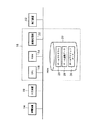
本発明の一実施例を図に基づいて説明する。図1は本発明のゲーム機のブロック図である。図2はゲーム機の入力装置を示す図である。
図1において、入力装置10と表示装置(モニタ)12と音響装置14とはゲーム機本体16に接続されている。入力装置10はゲームプレイヤーによって実際にスイングされるものであって、その移動に応じた電気信号を出力しゲーム機本体16に入力するものである。表示装置12はモニタ画面にゲーム画像を表示するものである。音響装置14はゲーム画像にあわせて効果音を出力するものである。ゲーム機本体16の内部には、CPU(中央処理装置)18,記憶装置(ROM)20,画像処理部22,RAM(メインメモリ)24のほか、表示装置10,音響装置14,入力装置12の各制御部が備えられている(図示せず)。前記記憶装置20はゲームプログラム26,ゲーム画像データ28,ホームポジションデータ30を保有している。
【0007】
前記入力装置10は、実際のゲームで使用されるゲーム用具を模したものである(図2)。ゲーム用具としては、例えば卓球のラケット,テニスのラケット,バトミントンのラケット,野球のバット,剣道の竹刀などが考えられる。本実施例では、卓球用ラケット(シェイクハンド)の形状を有する入力装置を用いる。また、ゲーム機は卓球ゲーム機として以下説明する。
【0008】
入力装置10のハウジング32は卓球ラケットの形状からなる。このハウジングは2つ割り部材によって形成され、2つの部材は複数対の固定部材38,39で固定されている。34は卓球ラケットの打球面部分に当る部分(打球面部)であり、36は卓球ラケットのグリップ部分に当る部分(グリップ部)である。なお、36aはグリップ部36の先端を示す。
【0009】
打球面部34側の内部には、2つの異なるセンサ40,42(信号出力手段)がプリント基板44に取付けられ固着されている。プリント基板44は固定部材39に取り付けられている。46はセンサ40,42より出力される電気信号をゲーム機本体16に入力するための入力線(コード)である。なお、上記のすべての機器は電気的に接続されているものとする。
【0010】
センサ40はX軸Y軸2軸の加速度センサである。加速度センサ40は入力装置10がスイングされた場合にその入力装置10の移動方向及び加速度(又は移動速度)を検出する。図3は、加速度センサが検出する入力装置の移動方向を示す図である。なお、図3中、グリップ部36の先端36aは図面手前に向いているものとする。34aはフォアハンド(右利きのプレーヤーの右側のスイング)の打球面とし、34bはバックハンド(右利きのプレーヤーの左側のスイング)の打球面とする。図3において、入力装置10がフォアハンドでスイングされる場合に入力装置10に対応するモニタ画面の位置をモニタ画面48aで示し、入力装置10がバックハンドでスイングされる場合に入力装置10に対応するモニタ画面の位置をモニタ画面48bで示す。
【0011】
加速度センサ40は、図3中の(a)方向乃至(d)方向のどの方向に入力装置10が振られているかを検出しその方向及びその速度に応じて電気信号(加速度信号)を出力する。(a)方向と(b)方向は入力装置の前後方向を示すものであり、(c)方向と(d)方向は入力装置の上下方向を示すものである。
例えば、ゲームプレイヤーがモニタ画面48aに向かってフォアハンドのスイングをしたとすると、(a)方向は打球面34aの進行方向(スイングの移動方向)を示す。一方、(a)方向の逆方向となる(b)方向はスイング前にとるバックスイングの方向を示す。また、(c)方向はそのスイングがドライブ打法によるものであることを示す。ドライブ打法は、ラケットを下方から上方に向けてボールをすりあげるようにスイングするものである。
他方、モニタ画面48bに向かってバックハンドのスイングをしたとすると、上記フォアハンドの場合と逆になるため、(b)方向は打球面34bの進行方向(スイングの移動方向)を示し、(a)方向はバックスイングの方向を示す。また、(d)方向はカット打法のスイング方向を示す。カット打法は、ラケットでボールの下をこするように上方から下方に向けてスイングするものである。
【0012】
また、加速度センサ40は、上記(a)方向乃至(d)方向とともに加速度(スイングの勢い)を検出する。従って、ゲームプレイヤーが入力装置10をスイングする場合は、加速度センサ40は(a)方向乃至(d)方向の移動方向及びその加速度に応じて電気信号を出力する。
【0013】
センサ42はX方向Y方向の地磁気(又は磁界)を検出する地磁気センサである。この地磁気センサ42は水平面を規定し、その水平面に対する入力装置の角度(又は傾き)に応じて電気信号を出力する。図4は入力装置の角度を示す図である。なお、図4については図3と同様に考える。グリップ部36の先端36aは図面手前に向いており、34aはフォアハンドの打球面とし、34bはバックハンドの打球面とする。また、入力装置10がフォアハンドでスイングされる場合に入力装置10に対応するモニタ画面の位置をモニタ画面48aで示し、入力装置10がバックハンドでスイングされる場合に入力装置10に対応するモニタ画面の位置をモニタ画面48bで示す。
【0014】
スイングの打法即ちドライブ打法,カット打法,ストレート打法で振られる場合の入力装置の角度を考えると、入力装置の角度は図4に示す3つに大別される。図4中のモニタ画面48aに向かってフォアハンドでスイングした場合、図中(1)の状態(図中の実線部)の入力装置10の中心線50と水平面52のなす角度Aは鋭角となり、上方向に加速度がある場合はドライブ打法となる。同様に、(2)の状態(図中の一点鎖線部)の角度Aは鈍角となり、下方向に加速度がある場合はカット打法となる。また、(3)の状態(図中の点線部)の角度(垂直)の場合は、前方向のみの加速度となるためストレート打法となる。
また、図5に示すように、図中の(ア)のフォアハンドでスイングされる打球面34aと(イ)のバックハンドでスイングされる打球面34bは逆の面となる。従って、図4中のモニタ画面48bに向かってバックハンドでスイングする場合は、(1)の状態の入力装置10の角度Bは鈍角をなし、下方向の加速度がある場合はカット打法となる。(2)の状態の角度Bは鋭角となり上方向の加速度がある場合はドライブ打法となる。ストレート打法はフォアハンドと同じである。
このように、地磁気センサ42により検出される(1)又は(2)の状態の入力装置10の角度によりフォアハンド又はバックハンドの判別ができ、さらには、加速度センサ40により上下方向の加速度を検出することによりフォアハンド又はバックハンドのスイングでドライブ打法又はカット打法が振られたかが判別できることになる。
【0015】
加速度センサ40が入力装置10の移動方向及び加速度に応じて電気信号(加速度信号)を出力し、地磁気センサ42が入力装置10の角度に応じて電気信号(地磁気信号)を出力し、その加速度信号と地磁気信号からなる入力信号を入力装置10からゲーム機本体16に入力する。ゲーム機本体16は、その入力された入力信号に基づいて、上記入力装置10の振られ方を判別しそのスイング(レシーブ)が有効か否かを判断する。
【0016】
次に、ゲーム機本体にて行われる入力信号の処理動作について説明する。図6は、入力信号を受信したゲーム機本体における処理動作を示すフローチャートである。本フローチャートでは、ゲームプレイヤーがフォアハンドのドライブ打法でモニタ画面48中のボールをレシーブした場合を考える。また、適当なレシーブはフォアハンドのスイングとする。なお、ゲームプレイヤーは入力装置10の表の面(例えば図2乃至図5に示す打球面34a)をフォアハンドの打球面として使用するものとする。
ステップS10では、ゲーム機本体16は入力装置10から入力される入力信号を受信する。続いてステップS11において、ゲーム機本体16のCPU18はその入力信号が記憶装置20のゲームプログラム26に設定された返球のタイミング範囲のものかどうかを判断する。タイミング範囲前の信号と判断した場合はステップS10に戻り新たな入力信号を受信する。なお、タイミング範囲を経過した後の入力信号は無効なものとして処理する。タイミング範囲の入力信号についてはステップS12に進む。
【0017】
ステップS12では、入力信号に加速度信号が存在するかを判断する。加速度信号が確認できないときは、ゲームプレイヤーはスイングしなかったものとして処理し、プレイを終了してキャラクタ側に1ポイントを加算し、次の新たなサービスゲームのプレイをスタートする。加速度信号が見つかった場合はステップS13に進む。
【0018】
ステップS13では、入力信号中の地磁気信号に基づいてゲームプレイヤーのスイングがフォアハンドによるものかを判断する。なお、フォアハンドの地磁気信号のデータはホームポジションデータ30として記憶装置20に入力されているものとする。CPU18は入力信号中の地磁気信号のデータをホームポジションデータ30と照合してフォアハンドのスイングか否かを判断する。本実施例では、フォアハンドのスイングがされているため入力信号中にはフォアハンドの地磁気信号が存在する。よって、フォアハンドのスイングと判断される。
ホームポジションデータ16に該当しない入力信号の場合は、CPU18はバックハンドのスイングがされたものとして判断し返球ミスとして処理する。この場合、プレイを終了してキャラクタ側に1ポイントを加算し次の新たなサービスゲームを開始するか、若しくは、ボールをチャンスボールとして返球する。
【0019】
ステップS14では、入力信号にバックスイングの加速度信号(図3に示す(b)方向の加速度信号)があるかを判断する。バックスイングの加速度信号が見つかったときは、ゲームプレイヤーは空振りしたものと判断し、そのプレイを終了しキャラクタ側に1ポイントを加算する。そして新たなサービスゲームを開始する。見つからなかった場合はスイングと判断しステップS15に進む。
【0020】
ステップS15ではスイングの打法を判断する。ゲームプレイヤーはドライブ打法でスイングしているため、入力信号中には上方向(図3の(c)方向)の加速度信号及び図4の(1)の入力装置10の角度Aの地磁気信号が存在する。従って、ステップS16において、ゲームプレイヤーのスイングはドライブ打法によるものであると判定される。また、入力信号にはドライブ打法以外の信号は存在しないためステップS17におけるストレート打法の判定及びステップS18におけるカット打法の判定はされない。
【0021】
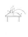
ステップS19では、CPU18はステップS17で判定した打法(ドライブ打法),スイングのタイミング,スイングの勢いに関する加速度信号,地磁気信号等に基づいてゲームプレイヤーの返球の移動パラメータを演算し決定する。また、演算された移動パラメータに対応するゲーム画像データ28を記憶装置20より抽出し生成し表示装置12に出力する。これにより、表示装置12のモニタ画面48上には、ドライブによる返球の軌跡を表わす画像が表示される。図7は、実際の卓球のプレイにおけるスイング打法毎のボールの軌道を示す図である。スイング打法毎のボールの軌道は卓球台(テーブル)54の側面から見ると図7に示すような▲1▼ドライブの軌道,▲2▼カットの軌道、▲3▼ストレートの軌道を描く。これらの軌道を、例えば図8に示すような軌跡でモニタ画面48に表わす。図8中、▲1▼の軌跡はドライブの軌道を示し、▲2▼の軌跡はカットの軌道を示し、▲3▼の軌跡はストレートの軌道を示すものとする。ゲームプレーヤーは、モニタ画面に表示される図8中の▲1▼のボールの軌跡を自分がスイングしたドライブ打法による軌跡と感じることで実際のプレイを体感することになる。
【0022】
また、スイングの打法を文字などで画面表示するようにしてもよい。さらには、音響装置14から打法別に異なる効果音を出力するようにしてもよい。
【0023】
なお、本実施例では卓球ゲーム機を例に説明したが、これに限るものではない。例えば入力装置を野球のバット,テニスのラケット,バトミントンのラケット,剣道の竹刀などを模した形状とするゲーム機であってもよい。
【0024】
【発明の効果】
本発明によると、入力装置に取付けられる加速度センサと地磁気センサが出力する加速度信号及び地磁気信号に基づいて入力装置の振られ方を判別できるため、その振られ方に対応して実際のボール等の種々の変化の軌跡をモニタ画面に表示することが可能となる。これにより、ゲームプレーヤーは様々なスイングでプレイを楽しむことができるとともに実際のプレイを体感できることになる。
また、無効なスイングは排除できることから、ゲームの興を削ぐこともない。
【図面の簡単な説明】
【図1】本発明のゲーム機を示すブロック図である。
【図2】ゲーム機の入力装置を示す図である。
【図3】入力装置の移動方向を示す図である。
【図4】入力装置の角度を示す図である。
【図5】入力装置の打球面を示す図である。
【図6】入力信号を受信したゲーム機の処理動作を示すフローチャートである。
【図7】実際の卓球のプレイにおけるスイング打法毎のボールの軌道を示す図である。
【図8】モニタ画面に表示されるスイング打法毎のボールの軌跡を示す図である。
【符号の説明】
10 入力装置
12 モニタ
16 ゲーム機本体
18 CPU
40 加速度センサ
42 地磁気センサ[0001]
BACKGROUND OF THE INVENTION
The present invention relates to a game machine capable of experiencing an actual game.
[0002]
[Prior art]
Among conventional game machines, there is known a game machine that uses an input device that imitates the shape of a game tool such as a baseball bat or table tennis racket (Japanese Patent Laid-Open No. 2001-104636). For example, a table tennis game machine disclosed in Japanese Patent Laid-Open No. 2001-104636 has a game player swing an input device having the same shape as an actual table tennis racket in the same manner as an actual table tennis racket, and experience an actual table tennis game. Is. In this table tennis game machine, an acceleration sensor (piezoelectric buzzer) is attached to the input device, the timing of the swing and the speed of the swing are judged based on the movement acceleration of the swing detected by the acceleration sensor, and the game player's receive (returning ball) is It was determined whether it was valid.
[0003]
[Problems to be solved by the invention]
However, since the player returns the ball based only on the swing timing and the swing speed, the conventional table tennis game machine cannot determine the forehand swing or the backhand swing performed by the game player. If the swing speed was appropriate, it was considered an effective return ball. Further, since the swing is effective if the timing and speed of the swing match, there is a problem that an invalid swing such as a back swing is also effective. For this reason, conventional game machines have been used to reduce the fun of the game.
In addition, there are batting methods that give various changes to the ball, such as a drive batting method and a cut batting method, which are basic swings in table tennis games. However, conventional table tennis game machines cannot discriminate the batting method. Therefore, the ball could not be changed and the actual game could not be experienced.
[0004]
An object of the present invention is to solve the above-described problem, and to provide a game machine that can determine how an input device is shaken so that a game player can experience an actual game. It is.
[0005]
[Means for Solving the Problems]
In order to achieve the above object, the present invention provides an input device that is shaken by a game player facing a monitor screen, an acceleration sensor and a geomagnetic sensor mounted inside the input device, and the two sensors that output the output device. In a game machine comprising a computer that simultaneously receives electrical signals, determines how the input device is shaken based on these signals, and displays an image of a ball game corresponding to the shake on the monitor screen The input device is formed in the shape of a racket for ball games, the acceleration sensor is formed of an acceleration sensor that outputs a speed signal according to the moving direction and acceleration of the input device, and the geomagnetic sensor is mounted on a horizontal plane. While forming from a geomagnetic sensor that outputs an angle signal according to the angle formed by the racket-shaped input device,
A storage device in which forehand geomagnetic signal data is input as home position data; and when the input device is shaken, the computer outputs an angle signal output by the geomagnetic sensor and the home position data of the storage device. To determine whether the forehand is due to the forehand , and further, the angle signal output from the geomagnetic sensor for the forehand is detected as an acute angle, and the acceleration sensor When the output speed signal detects that the acceleration is in the upward direction, the drive hitting method, when the angle is an obtuse angle and the acceleration is in the downward direction, the cut hitting method, and when the angle is vertical and the acceleration is If it is only in the forward direction, it is judged as a straight hitting method, and the trajectory of the ball corresponding to these hitting methods is determined. To display on the screen of the serial monitor.
[0006]
DETAILED DESCRIPTION OF THE INVENTION
An embodiment of the present invention will be described with reference to the drawings. FIG. 1 is a block diagram of a game machine of the present invention. FIG. 2 is a diagram showing an input device of the game machine.
In FIG. 1, an
[0007]
The
[0008]
The
[0009]
Two
[0010]
The
[0011]
The
For example, if the game player swings the forehand toward the
On the other hand, if a backhand swing is made toward the
[0012]
The
[0013]
The
[0014]
Considering the angle of the input device when swinging by the swing hitting method, that is, the drive hitting method, the cut hitting method, and the straight hitting method, the angle of the input device is roughly divided into three as shown in FIG. When the forehand is swung toward the
Further, as shown in FIG. 5, the hitting
As described above, the forehand or the backhand can be discriminated based on the angle of the
[0015]
The
[0016]
Next, an input signal processing operation performed in the game machine main body will be described. FIG. 6 is a flowchart showing the processing operation in the game machine main body that has received the input signal. In this flowchart, a case is considered where the game player receives the ball in the monitor screen 48 by the forehand drive hitting method. A suitable receive is a forehand swing. It is assumed that the game player uses the front surface of the input device 10 (for example, the hitting
In step S <b> 10, the
[0017]
In step S12, it is determined whether an acceleration signal exists in the input signal. When the acceleration signal cannot be confirmed, the game player treats it as not swinging, finishes playing, adds 1 point to the character side, and starts playing the next new service game. If an acceleration signal is found, the process proceeds to step S13.
[0018]
In step S13, it is determined whether the game player's swing is forehand based on the geomagnetic signal in the input signal. It is assumed that forehand geomagnetic signal data is input to the
In the case of an input signal not corresponding to the
[0019]
In step S14, it is determined whether there is a backswing acceleration signal (acceleration signal in the direction (b) shown in FIG. 3) in the input signal. When a backswing acceleration signal is found, the game player determines that the player has missed, ends the play, and adds 1 point to the character side. And a new service game is started. If not found, it is determined as a swing and the process proceeds to step S15.
[0020]
In step S15, a swing hitting method is determined. Since the game player swings by the driving hitting method, the acceleration signal in the upward direction (direction (c) in FIG. 3) and the geomagnetic signal at the angle A of the
[0021]
In step S19, the
[0022]
Also, the swing hitting method may be displayed on the screen with characters or the like. Further, different sound effects may be output from the
[0023]
In this embodiment, a table tennis game machine has been described as an example, but the present invention is not limited to this. For example, the input device may be a game machine having a shape imitating a baseball bat, a tennis racket, a badminton racket, a kendo bamboo sword, or the like.
[0024]
【The invention's effect】
According to the present invention, it is possible to determine how to shake the input device based on the acceleration signal and the geomagnetic signal output from the acceleration sensor and the geomagnetic sensor attached to the input device. It is possible to display various changes on the monitor screen. As a result, the game player can enjoy playing with various swings and can experience the actual play.
In addition, since the invalid swing can be eliminated, the game is not lost.
[Brief description of the drawings]
FIG. 1 is a block diagram showing a game machine of the present invention.
FIG. 2 is a diagram showing an input device of the game machine.
FIG. 3 is a diagram illustrating a moving direction of the input device.
FIG. 4 is a diagram illustrating an angle of an input device.
FIG. 5 is a diagram showing a hitting surface of the input device.
FIG. 6 is a flowchart showing a processing operation of a game machine that has received an input signal.
FIG. 7 is a diagram showing a ball trajectory for each swing hitting method in actual table tennis play.
FIG. 8 is a diagram illustrating a trajectory of a ball for each swing hitting method displayed on a monitor screen.
[Explanation of symbols]
10
40
Claims (2)
前記入力装置は外形を球技用のラケット状に形成し、
前記加速度センサを前記入力装置の移動方向及び加速度に応じて速度信号を出力する加速度センサから形成し、
前記地磁気センサを水平面に対してラケット状の前記入力装置がなす角度に応じて角度信号を出力する地磁気センサから形成するとともに、
フォアハンドの地磁気信号のデータがホームポジションデータとして入力されている記憶装置を備え、
前記入力装置が振られる場合に前記コンピュータは、前記地磁気センサが出力する角度信号と前記記憶装置の前記ホームポジションデータとを照合して、
フォアハンドによるものか否かを判別し、更にフォアハンドであって前記地磁気センサが出力する角度信号により前記入力装置と水平面のなす角度が鋭角であると検出され、且つ前記加速度センサが出力した前記速度信号により加速度が上方向にあると検出された場合はドライブ打法と、前記角度が鈍角で且つ加速度が下方向にある場合はカット打法と、前記角度が垂直で且つ加速度が前方向にのみある場合はストレート打法とそれぞれ判定し、これらの打法に対応したボールの軌跡を前記モニタの画面上に表示することを特徴とするゲーム機。An input device that is shaken by a game player facing the monitor screen, an acceleration sensor and a geomagnetic sensor mounted inside the input device, and an electrical signal output by the two sensors are simultaneously received, and based on these signals In a game machine comprising a computer that determines how the input device is shaken and displays an image of a ball game corresponding to this shake on the screen of the monitor,
The input device forms an outer shape in a racket shape for ball games,
The acceleration sensor is formed from an acceleration sensor that outputs a speed signal according to the moving direction and acceleration of the input device,
While forming the geomagnetic sensor from a geomagnetic sensor that outputs an angle signal according to the angle formed by the racket-shaped input device with respect to a horizontal plane,
A storage device is provided in which forehand geomagnetic signal data is input as home position data.
When the input device is shaken, the computer collates the angle signal output from the geomagnetic sensor with the home position data of the storage device ,
The velocity signal output from the acceleration sensor is detected by determining whether the forehand is a forehand, and further detecting that the angle between the input device and the horizontal plane is an acute angle based on the angle signal output from the geomagnetic sensor. If the acceleration is detected to be upward, the drive hitting method is used. If the angle is obtuse and the acceleration is downward, the cut hitting method is used. The angle is vertical and the acceleration is only forward. In this case, the game machine is characterized in that a straight hitting method is determined, and a ball trajectory corresponding to these hitting methods is displayed on the screen of the monitor.
Priority Applications (1)
| Application Number | Priority Date | Filing Date | Title |
|---|---|---|---|
| JP2001368637A JP3763776B2 (en) | 2001-12-03 | 2001-12-03 | game machine |
Applications Claiming Priority (1)
| Application Number | Priority Date | Filing Date | Title |
|---|---|---|---|
| JP2001368637A JP3763776B2 (en) | 2001-12-03 | 2001-12-03 | game machine |
Publications (2)
| Publication Number | Publication Date |
|---|---|
| JP2003164667A JP2003164667A (en) | 2003-06-10 |
| JP3763776B2 true JP3763776B2 (en) | 2006-04-05 |
Family
ID=19178199
Family Applications (1)
| Application Number | Title | Priority Date | Filing Date |
|---|---|---|---|
| JP2001368637A Expired - Fee Related JP3763776B2 (en) | 2001-12-03 | 2001-12-03 | game machine |
Country Status (1)
| Country | Link |
|---|---|
| JP (1) | JP3763776B2 (en) |
Families Citing this family (5)
| Publication number | Priority date | Publication date | Assignee | Title |
|---|---|---|---|---|
| JP2005040493A (en) * | 2003-07-25 | 2005-02-17 | Hori Co Ltd | Controller for video game machine |
| WO2005119356A2 (en) | 2004-05-28 | 2005-12-15 | Erik Jan Banning | Interactive direct-pointing system and calibration method |
| US9285897B2 (en) | 2005-07-13 | 2016-03-15 | Ultimate Pointer, L.L.C. | Easily deployable interactive direct-pointing system and calibration method therefor |
| JP5173174B2 (en) * | 2006-09-13 | 2013-03-27 | 任天堂株式会社 | GAME DEVICE, GAME PROGRAM, GAME SYSTEM, AND GAME PROCESSING METHOD |
| CN113856191B (en) * | 2020-06-30 | 2024-04-12 | 广州拓火科技有限公司 | Man-machine interactive game system |
Family Cites Families (7)
| Publication number | Priority date | Publication date | Assignee | Title |
|---|---|---|---|---|
| JPH0724140A (en) * | 1993-07-07 | 1995-01-27 | Sega Enterp Ltd | Game device |
| JP3351510B2 (en) * | 1998-05-22 | 2002-11-25 | 株式会社センテクリエイションズ | Tennis experience play toys |
| JP2000089906A (en) * | 1998-09-08 | 2000-03-31 | Nadex Co Ltd | Direction data output device |
| JP2000308756A (en) * | 1999-04-27 | 2000-11-07 | Taito Corp | Input controller of game device |
| JP3799190B2 (en) * | 1999-05-10 | 2006-07-19 | 株式会社タイトー | Music conductor game device |
| JP2001062150A (en) * | 1999-08-27 | 2001-03-13 | Namco Ltd | Game system and information storage medium |
| JP3824462B2 (en) * | 2000-02-24 | 2006-09-20 | 株式会社バンダイナムコゲームス | GAME DEVICE AND INFORMATION STORAGE MEDIUM |
-
2001
- 2001-12-03 JP JP2001368637A patent/JP3763776B2/en not_active Expired - Fee Related
Also Published As
| Publication number | Publication date |
|---|---|
| JP2003164667A (en) | 2003-06-10 |
Similar Documents
| Publication | Publication Date | Title |
|---|---|---|
| US9033782B2 (en) | Sensing ball game machine | |
| US7635301B2 (en) | Game system | |
| JP4151982B2 (en) | Motion discrimination device and motion discrimination program | |
| JP4330593B2 (en) | GAME DEVICE AND GAME PROGRAM | |
| US20110172017A1 (en) | Game machine, game program, and game machine control method | |
| US20100203969A1 (en) | Game device, game program and game object operation method | |
| CN101496954B (en) | Game controller and game processing method thereof | |
| WO2002066128A1 (en) | Program for controlling playing of game, and game apparatus for running this program | |
| JP2003126548A (en) | Game device and game system | |
| JP2006129942A (en) | Program, information storage medium, and game machine | |
| JP2002052246A (en) | Game machine | |
| JP2002007057A (en) | Input device for processor | |
| JP5396212B2 (en) | GAME DEVICE, GAME DEVICE CONTROL METHOD, AND PROGRAM | |
| JP3763776B2 (en) | game machine | |
| JP2003190636A (en) | Video game program, readable recording medium on which video game program is recorded, method, and video game device | |
| JPH01274780A (en) | Boxing game machine | |
| JP3750103B2 (en) | Recording medium and game device | |
| JP4771343B2 (en) | Experience game device, experience game method, and recording medium | |
| JP2011056140A (en) | Program, information storage medium, and game device | |
| JPH09182875A (en) | Operation method and game device | |
| JP4831261B2 (en) | Input device for processor | |
| JP2001238991A (en) | Game device | |
| US20230249068A1 (en) | Information processing system, computer-readable non-transitory storage medium having information processing program stored therein, information processing apparatus, and information processing method | |
| JPH08280864A (en) | Ball game exercising machine | |
| JP2011243225A (en) | Input device for processor |
Legal Events
| Date | Code | Title | Description |
|---|---|---|---|
| A621 | Written request for application examination |
Free format text: JAPANESE INTERMEDIATE CODE: A621 Effective date: 20040622 |
|
| A131 | Notification of reasons for refusal |
Free format text: JAPANESE INTERMEDIATE CODE: A131 Effective date: 20050621 |
|
| A521 | Written amendment |
Free format text: JAPANESE INTERMEDIATE CODE: A523 Effective date: 20050818 |
|
| A131 | Notification of reasons for refusal |
Free format text: JAPANESE INTERMEDIATE CODE: A131 Effective date: 20050920 |
|
| A521 | Written amendment |
Free format text: JAPANESE INTERMEDIATE CODE: A523 Effective date: 20051011 |
|
| A131 | Notification of reasons for refusal |
Free format text: JAPANESE INTERMEDIATE CODE: A131 Effective date: 20051115 |
|
| A521 | Written amendment |
Free format text: JAPANESE INTERMEDIATE CODE: A523 Effective date: 20051207 |
|
| TRDD | Decision of grant or rejection written | ||
| A01 | Written decision to grant a patent or to grant a registration (utility model) |
Free format text: JAPANESE INTERMEDIATE CODE: A01 Effective date: 20060110 |
|
| A61 | First payment of annual fees (during grant procedure) |
Free format text: JAPANESE INTERMEDIATE CODE: A61 Effective date: 20060117 |
|
| R150 | Certificate of patent or registration of utility model |
Free format text: JAPANESE INTERMEDIATE CODE: R150 Ref document number: 3763776 Country of ref document: JP Free format text: JAPANESE INTERMEDIATE CODE: R150 |
|
| S111 | Request for change of ownership or part of ownership |
Free format text: JAPANESE INTERMEDIATE CODE: R313111 |
|
| R371 | Transfer withdrawn |
Free format text: JAPANESE INTERMEDIATE CODE: R371 |
|
| S111 | Request for change of ownership or part of ownership |
Free format text: JAPANESE INTERMEDIATE CODE: R313111 |
|
| R350 | Written notification of registration of transfer |
Free format text: JAPANESE INTERMEDIATE CODE: R350 |
|
| S531 | Written request for registration of change of domicile |
Free format text: JAPANESE INTERMEDIATE CODE: R313531 |
|
| FPAY | Renewal fee payment (event date is renewal date of database) |
Free format text: PAYMENT UNTIL: 20090127 Year of fee payment: 3 |
|
| R350 | Written notification of registration of transfer |
Free format text: JAPANESE INTERMEDIATE CODE: R350 |
|
| FPAY | Renewal fee payment (event date is renewal date of database) |
Free format text: PAYMENT UNTIL: 20090127 Year of fee payment: 3 |
|
| FPAY | Renewal fee payment (event date is renewal date of database) |
Free format text: PAYMENT UNTIL: 20100127 Year of fee payment: 4 |
|
| FPAY | Renewal fee payment (event date is renewal date of database) |
Free format text: PAYMENT UNTIL: 20100127 Year of fee payment: 4 |
|
| FPAY | Renewal fee payment (event date is renewal date of database) |
Free format text: PAYMENT UNTIL: 20110127 Year of fee payment: 5 |
|
| S111 | Request for change of ownership or part of ownership |
Free format text: JAPANESE INTERMEDIATE CODE: R313111 |
|
| FPAY | Renewal fee payment (event date is renewal date of database) |
Free format text: PAYMENT UNTIL: 20110127 Year of fee payment: 5 |
|
| R350 | Written notification of registration of transfer |
Free format text: JAPANESE INTERMEDIATE CODE: R350 |
|
| FPAY | Renewal fee payment (event date is renewal date of database) |
Free format text: PAYMENT UNTIL: 20110127 Year of fee payment: 5 |
|
| FPAY | Renewal fee payment (event date is renewal date of database) |
Free format text: PAYMENT UNTIL: 20120127 Year of fee payment: 6 |
|
| FPAY | Renewal fee payment (event date is renewal date of database) |
Free format text: PAYMENT UNTIL: 20120127 Year of fee payment: 6 |
|
| FPAY | Renewal fee payment (event date is renewal date of database) |
Free format text: PAYMENT UNTIL: 20130127 Year of fee payment: 7 |
|
| FPAY | Renewal fee payment (event date is renewal date of database) |
Free format text: PAYMENT UNTIL: 20130127 Year of fee payment: 7 |
|
| FPAY | Renewal fee payment (event date is renewal date of database) |
Free format text: PAYMENT UNTIL: 20140127 Year of fee payment: 8 |
|
| FPAY | Renewal fee payment (event date is renewal date of database) |
Free format text: PAYMENT UNTIL: 20140127 Year of fee payment: 8 |
|
| S531 | Written request for registration of change of domicile |
Free format text: JAPANESE INTERMEDIATE CODE: R313531 |
|
| FPAY | Renewal fee payment (event date is renewal date of database) |
Free format text: PAYMENT UNTIL: 20140127 Year of fee payment: 8 |
|
| R350 | Written notification of registration of transfer |
Free format text: JAPANESE INTERMEDIATE CODE: R350 |
|
| LAPS | Cancellation because of no payment of annual fees |