JP3661466B2 - Coating unevenness inspection apparatus and method - Google Patents
Coating unevenness inspection apparatus and method Download PDFInfo
- Publication number
- JP3661466B2 JP3661466B2 JP00642999A JP642999A JP3661466B2 JP 3661466 B2 JP3661466 B2 JP 3661466B2 JP 00642999 A JP00642999 A JP 00642999A JP 642999 A JP642999 A JP 642999A JP 3661466 B2 JP3661466 B2 JP 3661466B2
- Authority
- JP
- Japan
- Prior art keywords
- coating unevenness
- painted surface
- image data
- light
- image
- Prior art date
- Legal status (The legal status is an assumption and is not a legal conclusion. Google has not performed a legal analysis and makes no representation as to the accuracy of the status listed.)
- Expired - Fee Related
Links
Images


Description
【0001】
【発明の属する技術分野】
本発明は、塗装欠陥のうちの塗装ムラ、特に、塗装面の広い範囲で発生するメタリック塗装の塗装ムラ(メタリック塗装ムラ)の検査に好適な塗装ムラ検査装置および方法に関する。
【0002】
【従来の技術】
メタリック塗装時に発生する塗装ムラ(メタリック塗装ムラ)は光輝材の配列乱れによって起こるが、その原因として塗装機のパターン乱れ、シンナー過量、膜厚不足、中塗り部の研磨不良などがある。このような塗装ムラ不良に対して、従来は、ほとんど目視により官能的に評価を行っているのが現状である。
【0003】
例えば、自動車塗装の場合、上塗り乾燥後のボディーを検査ラインにおいて作業者が目視により塗装ムラの有無を確認し、塗装ムラ不良が有りそうであると判断したボディーについてライン外に抜き出して、専用の検査場で検査を行う。検査場では、人工太陽灯などの高光束のランプをボディーに照射し、さらにムラ部がはっきり見えるよう工夫して、目視による評価を行う。このとき、塗装ムラ不良の程度は経験値で判断しているのが現状である。
【0004】
また、最近では、メタリック塗装面の輝度を測定する装置(レーザー式メタリック感測定器など)が開発され、この装置で塗装面を走査して輝度を連続測定または多点測定することにより、輝度分布図などを用いて塗装ムラを定量評価する方法が考案されている(例えば、特開平5−288690号公報参照)。また、同様に色差計により明度値を多点測定し、そのデータをもとにある程度定量的に評価する方法も考案されている。
【0005】
【発明が解決しようとする課題】
しかし、作業者による目視測定では、光源の当て方により塗装ムラの見える、見えないが顕著であるため、不良品の流出が発生しやすい。また、目視による官能評価であり定量評価されていないため、検査結果に個人差が出やすい。
【0006】
また、測定器で検査・評価する場合には、基本的に点測定であるため、広い視野での測定は難しい。そのため、ボディー表面の広い範囲で発生するメタリック塗装ムラの場合には、測定精度が問題になる。また、多数の測定データが必要になるため、測定結果が出るまでに多くの時間(工数)を要するという問題もある。
【0007】
本発明は、上記従来技術の問題点に鑑みてなされたものであり、ライン上において広い視野で塗装ムラの定量評価を行うことができる塗装ムラ検査装置および方法を提供することを目的とする。
【0008】
【課題を解決するための手段】
本発明の上記目的は、下記の手段によって達成される。
【0009】
(1)本発明に係る塗装ムラ検査装置は、被検査物の塗装面に発生する塗装ムラを光学的に測定し、評価する塗装ムラ検査装置において、前記被検査物の塗装面に対して所定の角度で光を照射する光源と、前記光源のシェード側に設置され、前記光源により光が照射された塗装面の画像を所定範囲の視野で画像データとして取り込む撮像手段と、前記撮像手段によって取り込まれた画像データを解析して、塗装ムラに関する定量的な評価値を算出する解析手段と、前記解析手段によって算出された評価値をあらかじめ設定された基準値と比較して、塗装ムラの発生の有無を判定する判定手段と、を有することを特徴とする。
【0010】
(2)前記光源は塗装面に対して45度の角度で光を照射し、前記撮像手段の光軸と塗装面との成す角度は45度よりも小さい。
【0011】
(3)撮像手段によって取り込まれた画像データに対して輝度ヒストグラム解析を行って、輝度値の分布幅を算出するとともに、同じ画像データに対してラインプロファイル解析を行って、輝度値の強弱差を算出する解析手段と、前記解析手段によって算出された分布幅および強弱差をあらかじめ設定された各々の基準値と比較して、塗装ムラの発生の有無を判定する判定手段とを有する。
【0012】
(4)上記のラインプロファイル解析では、水平方向および高さ方向に広がった画像の画像データに基づいて、前記水平方向に沿って一定の高さの幅での輝度平均値を算出してラインプロファイルを解析し、ラインプロファイルでの輝度値の強弱差を算出する。
【0013】
(5)前記光源により光が照射された塗装面において水平方向および高さ方向に広がった画像を所定範囲の視野で画像データとして取り込む撮像手段と、前記撮像手段によって取り込まれた、水平方向および高さ方向に広がった画像の画像データに基づいて、前記水平方向に沿って一定の高さの幅での輝度平均値を算出してラインプロファイルを解析し、ラインプロファイルでの輝度値の強弱差を算出する解析手段と、前記解析手段によって算出された強弱差をあらかじめ設定された基準値と比較して、塗装ムラの発生の有無を判定する判定手段と、を有する。
【0014】
(6)本発明に係る塗装ムラ検査方法は、被検査物の塗装面に発生する塗装ムラを光学的に測定し、評価する塗装ムラ検査方法において、被検査物の塗装面に対して光源により所定の角度で光を照射する工程と、前記光源により光が照射された塗装面の画像を所定範囲の視野で画像データとして、前記光源のシェード側に設置された撮像手段により取り込む工程と、前記撮像手段によって取り込まれた画像データを解析して、塗装ムラに関する定量的な評価値を算出する工程と、算出された評価値をあらかじめ設定された基準値と比較して、塗装ムラの発生の有無を判定する工程と、を有することを特徴とする。
【0015】
(7)前記光源は塗装面に対して45度の角度で光を照射し、前記撮像手段の光軸と塗装面との成す角度は45度よりも小さい。
【0016】
(8)取り込まれた画像データに対して輝度ヒストグラム解析を行って、輝度値の分布幅を算出するとともに、同じ画像データに対してラインプロファイル解析を行って、輝度値の強弱差を算出する工程と、算出された分布幅および強弱差をあらかじめ設定された各々の基準値と比較して、塗装ムラの発生の有無を判定する工程と、を有する。
【0017】
(9)上記のラインプロファイル解析では、水平方向および高さ方向に広がった画像の画像データに基づいて、前記水平方向に沿って一定の高さの幅での輝度平均値を算出してラインプロファイルを解析し、ラインプロファイルでの輝度値の強弱差を算出する。
【0018】
(10)光が照射された塗装面において水平方向および高さ方向に広がった画像を所定範囲の視野で画像データとして取り込む工程と、取り込まれた、水平方向および高さ方向に広がった画像の画像データに基づいて、前記水平方向に沿って一定の高さの幅での輝度平均値を算出してラインプロファイルを解析し、ラインプロファイルでの輝度値の強弱差を算出する工程と、算出された強弱差をあらかじめ設定された基準値と比較して、塗装ムラの発生の有無を判定する工程と、を有する。
【0022】
【発明の効果】
本発明によれば、塗装面に光を照射して所定範囲の視野で塗装面を撮像し、つまり目視で見える塗装面の映像をそのまま画像として取り込み、画像解析を行って塗装ムラの定量的な評価値を算出するので、広い視野で塗装ムラの定量評価を高精度に短時間で行うことが可能となるのみならず、目視による官能評価では達成できない客観的な評価が可能となり、検査結果に個人差が出なくなる。
【0023】
その際、光源に人工太陽灯を用い、また、光源の角度を塗装面に対して45°とすることにより、塗装ムラの検出が容易になる。また、撮像手段にCCDエリアカメラを用いることにより視野を広くとることができ、また、撮像手段の設置位置を光源のシェード側とすることによりほとんどすべての塗装ムラを検出できるようになる。したがって、特に、広い範囲で発生し従来検出が難しかったメタリック塗装ムラに対して有効である。
【0024】
また、被検査物全体を同時に測定する場合、複数組の光源と撮像手段を並列して設置することにより、被検査物全体をカバーする広い視野で被検査物全体の塗装ムラ不良を検知できるため、検査の見落としによる不良品の流出が可及的に防止される。
【0025】
また、被検査物がライン上に存在する場合には、ライン上を通過する被検査物に対する定量測定・評価が可能となり、ライン上での検査が可能となるため、被検査物のライン外しがなくなる。この点からも、検査時間(工程)の短縮が図られる。
【0026】
【発明の実施の形態】
以下、本発明の実施の形態を図面に基づいて説明する。
【0027】
図1は、本発明の一実施の形態に係る塗装ムラ検査装置の概略構成を示すブロック図である。
【0028】
この装置は、自動車のボディー1表面の広い範囲で発生するメタリック塗装ムラの検査に好適なものであって、その概要として、視野を大きくとるためにCCDカメラ2を使用し、塗装面に人工太陽灯3の光を照射して目視で見える映像をそのまま画像として取り込み、画像解析ソフトウェアによる画像処理を行ってメタリック塗装ムラの有無の定量評価を行うように構成されている。
【0029】
より具体的な装置構成としては、自動車ボディー1(被検査物)の塗装面を照射する人工太陽灯3(光源)と、塗装面の映像を撮影するCCDエリアカメラ(以下単に「CCDカメラ」という)2(撮像手段)と、CCDカメラ2からのアナログの画像データ信号を取り込んでデジタルの画像データ信号に変換する画像取込み装置4と、塗装ムラ検査用の画像処理ソフトウェアを搭載した画像処理装置5とから成り、画像処理装置5は、さらに、取り込まれた画像データを解析して、メタリック塗装ムラに関する定量的な評価値を算出する画像解析部6(解析手段)と、算出された評価値をあらかじめ設定された基準値と比較して、メタリック塗装ムラの発生の有無を判定する判定部7(判定手段)と、前記基準値を記憶するメモリ8とから成っている。また、画像処理装置5の各部の処理結果をオペレータに表示するため、画像処理装置5には表示装置9が接続されている。
【0030】
自動車ボディー1の全体を同時測定する場合には、少なくとも光源(人工太陽灯)3とCCDカメラ2について複数組用意し、これらを並列して設置することにより、ボディー1全体をカバーしうる広い視野を確保する。例えば、図1の例では、ライン上を搬送されるボディー1の搬送方向Aの前方に4組の人工太陽灯3とCCDカメラ2、具体的には、搬送方向Aに向かって右側のサイド部の人工太陽灯3aとCCDカメラ2a、右側の水平部用の人工太陽灯3bとCCDカメラ2b、左側の水平部用の人工太陽灯3cとCCDカメラ2c、左側のサイド部の人工太陽灯3dとCCDカメラ2dが設置されている。
【0031】
上記構成において、光源に人工太陽灯3を用いるのは、高光束の光を塗装面に照射して塗装ムラの検出を容易にするためである。また、塗装面に対する光源(人工太陽灯)3の設置角度は、光源3の光軸と塗装面との成す角度が45°であることが好ましい。この場合、光源3からの光は塗装面に対して45°の角度で入射することになる。
【0032】
また、CCDカメラ2の位置は、光源3のシェード(底)側に設置することが好ましい。これにより、ほとんどすべての塗装ムラを検出することができる。すなわち、塗装面に対するCCDカメラ2の設置角度(画像取込み角度)は、CCDカメラ2の光軸と塗装面との成す角度が光源(人工太陽灯)3からの光の入射角の45°よりも小さい方が、ほとんどのメタリック塗装ムラに対して有効となり、好ましい。
【0033】
図2は、図1の塗装ムラ検査装置の動作を示すフローチャートである。
【0034】
まず、各人工太陽灯3a〜3dを点灯(ON)して塗装面に対して45°の入射角度で光を照射し(S1)、その時の塗装面の映像を各光源のシェード側より対応するCCDカメラ2a〜2dでそれぞれ撮影して画像データとして取り込む(S2)。
【0035】
CCDカメラ2で撮像された画像データは、画像取込み装置4を介して画像処理装置5に入力され、まず画像解析部6で、画像解析ソフトウェアにより輝度ヒストグラム解析および/またはラインプロファイル解析を行って、塗装ムラを定量的に表現する定量的な評価値を算出する(S3)。輝度ヒストグラム解析は、輝度値のヒストグラム分布を解析して、前記評価値として輝度値の分布幅を求める手法であり(図4参照)、ラインプロファイル解析は、輝度平均値のラインプロファイルを解析して、前記評価値として輝度値の強弱差を求める手法である(図5参照)。これらの輝度ヒストグラム解析およびラインプロファイル解析については、後で詳細に説明する。
【0036】
画像解析を行ってメタリック塗装ムラの定量測定が終了すると、次に判定部7で、解析結果を正常部位のデータと比較することにより塗装ムラの定量評価を行う、具体的には、S3で算出された評価値をあらかじめ設定されたメモリ8記憶の基準値と比較して、メタリック塗装ムラの発生の有無(程度を含む)を判定する(S4)。なお、評価レベル(基準値)については、従来から積み重ねてきた経験値を基にしきい値をあらかじめ決め、メモリ8に格納しておく。
【0037】
S4の判定結果は、表示装置9に表示される(S5)。なお、このとき、例えば、オペレータの選択に応じて、中間のS3の解析結果(輝度ヒストグラムとその評価値、または、ラインプロファイルとその評価値)をも表示するようにしてもよい。
【0038】
したがって、本実施の形態によれば、広い視野で、通過するボディー1全体のメタリック塗装ムラ不良を見ることができるため、検査の見落としによる不良品の流出が可及的に防止される。
【0039】
また、ライン上で検査することができるため、ボディー1のライン外しがなくなる。
【0040】
さらに、メタリック塗装ムラを定量評価することができるため、評価自体が客観的で、検査結果に個人差が出ない。
【0041】
【実施例】
以下に、具体例を説明する。
【0042】
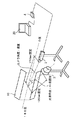
図3は、本発明の一実施例に係る塗装ムラ検査装置の構成図である。なお、同図中、図1と共通する部材には同一の符号を付してある。
【0043】
被検査物は、塗色シルバーのドアアウター10であり、光源は、人工太陽灯3であり、CCDカメラ2は、カラーCCDカメラ(レンズ:COSMICAR TV ZOOM LENS 12.5〜75mm)である。このカラーCCDカメラ2には、画像取込み装置(V−Port)4を介してパソコン20が接続されている。パソコンは、図1の画像処理装置5と表示装置9を兼ねたものである。そして、ドアアウター10、人工太陽灯3、およびカラーCCDカメラ2の相互位置関係については、人工太陽灯3は、ドアアウター10の塗装面に対して45°の角度で、かつ、ドアアウター10の塗装面から1250mmの位置に固定され、また、カラーCCDカメラ2は、人工太陽灯3の光軸とドアアウター10との交点から1700mmの位置に固定されている。塗装面に対するカラーCCDカメラ2の角度(CCDカメラ角度)は、人工太陽灯3の入射角である45°よりも小さい範囲内で、その都度、適宜に設定される。
【0044】
図4は、輝度ヒストグラム解析による画像処理結果例を示す図面であって、塗装ムラ発生ドア(同図(A))とOKレベルドア(同図(B))とを対比したものである。
【0045】
具体的には、図3の装置により、CCDカメラ角度25°で、メタリック塗装ムラの発生しているドアと目視評価によりOKレベルのドアのそれぞれについて撮像し、それぞれ取り込んだ画像の一定範囲について輝度値のヒストグラムをプロットすると、図4(A)および図4(B)に示すようになる。これら両図面の対比から明らかなように、塗装ムラの度合が大きいほど輝度値のバラツキが大きくなるため、輝度値分布の幅が広くなる。したがって、この輝度値分布幅を用いて塗装ムラを定量的に表現することができる。
【0046】
図5は、ラインプロファイル解析による画像処理結果例を示す図面であって、塗装ムラ発生ドア(同図(A))とOKレベルドア(同図(B))とを対比したものである。
【0047】
具体的には、輝度ヒストグラム解析に用いたのと同じ画像を、ドアの前後方向(ピクセル位置または水平方向座標)に沿って、一定の高さの幅での輝度平均値を算出し、プロットすると、それぞれ図5(A)および図5(B)に示すようになる。これら両図面の対比から明らかなように、軌跡ムラのような縦方向に筋の生じている塗装ムラについては、その度合が大きいほど輝度値の強弱差が大きくなるため、このラインプロファイルでの輝度値の強弱差を計測することによってこの種の塗装ムラを定量化することができる。
【0048】
なお、実験の結果として、CCDカメラ2の画像取込み角度条件(CCDカメラ角度)は、上記したように、人工太陽灯3の入射角の45°よりも小さい方がほとんどのメタリック塗装ムラに対して有効である。
【図面の簡単な説明】
【図1】 本発明の一実施の形態に係る塗装ムラ検査装置の概略構成を示すブロック図である。
【図2】 図1の塗装ムラ検査装置の動作を示すフローチャートである。
【図3】 本発明の一実施例に係る塗装ムラ検査装置の構成図である。
【図4】 輝度ヒストグラム解析による画像処理結果例を示す図面である。
【図5】 ラインプロファイル解析による画像処理結果例を示す図面である。
【符号の説明】
1…自動車ボディー(被検査物)、
2…CCDエリアカメラ(撮像手段)、
3…人工太陽灯(光源)、
4…画像取込み装置、
5…画像処理装置、
6…画像解析部(解析手段)、
7…判定部(判定手段)、
8…基準値メモリ、
9…表示装置、
10…ドアアウター、
20…パソコン。[0001]
BACKGROUND OF THE INVENTION
The present invention relates to a coating unevenness inspection apparatus and method suitable for inspection of coating unevenness among coating defects, in particular, coating unevenness (metallic coating unevenness) of metallic coating that occurs in a wide range of a painted surface.
[0002]
[Prior art]
The coating unevenness (metallic coating unevenness) generated at the time of metallic coating is caused by the disorder of the arrangement of the glitter material. The causes include the pattern disorder of the coating machine, excessive amount of thinner, insufficient film thickness, and poor polishing of the intermediate coating part. In the past, such an uneven coating defect has been evaluated sensuously almost visually.
[0003]
For example, in the case of automobile painting, the body after drying the topcoat is visually checked on the inspection line for the presence of uneven coating, and the body that is judged to have poor coating unevenness is extracted outside the line. Inspect at the inspection site. At the inspection site, the body is irradiated with a high luminous flux lamp, such as an artificial sun lamp, and further devised so that the unevenness can be clearly seen, and then visual evaluation is performed. At this time, the degree of coating unevenness is currently determined based on empirical values.
[0004]
Recently, devices that measure the brightness of metallic paint surfaces (laser-type metallic sensation measuring devices, etc.) have been developed, and this device scans the paint surface to measure the brightness continuously or by measuring multiple points. A method of quantitatively evaluating the coating unevenness using a figure or the like has been devised (see, for example, JP-A-5-288690). Similarly, a method has been devised in which lightness values are measured at multiple points using a color difference meter and evaluated to some extent based on the data.
[0005]
[Problems to be solved by the invention]
However, in visual measurement by an operator, coating unevenness is visible or not visible depending on how the light source is applied, but it is noticeable that defective products are likely to flow out. Moreover, since it is visual sensory evaluation and is not quantitatively evaluated, individual differences are likely to appear in the test results.
[0006]
In addition, when inspecting and evaluating with a measuring instrument, since it is basically point measurement, measurement with a wide field of view is difficult. Therefore, in the case of metallic coating unevenness that occurs over a wide range of the body surface, measurement accuracy becomes a problem. In addition, since a large amount of measurement data is required, there is also a problem that a lot of time (man-hours) is required until a measurement result is obtained.
[0007]
The present invention has been made in view of the above-described problems of the prior art, and an object thereof is to provide a coating unevenness inspection apparatus and method capable of performing quantitative evaluation of coating unevenness with a wide field of view on a line.
[0008]
[Means for Solving the Problems]
The above object of the present invention is achieved by the following means.
[0009]
(1) A coating unevenness inspection apparatus according to the present invention is a coating unevenness inspection apparatus that optically measures and evaluates coating unevenness generated on a painted surface of an object to be inspected. A light source that emits light at an angle of, an imaging unit that is installed on the shade side of the light source, and that captures an image of a painted surface irradiated with light from the light source as image data within a predetermined field of view, and is captured by the imaging unit The analysis means for analyzing the image data and calculating a quantitative evaluation value for coating unevenness, and comparing the evaluation value calculated by the analyzing means with a preset reference value, Determining means for determining presence or absence.
[0010]
(2) wherein the light source emits light at an angle of 45 degrees with respect to painted surfaces, angle between the optical axis and the coated surface of the image pickup means is smaller than 45 degrees.
[0011]
(3) A luminance histogram analysis is performed on the image data captured by the imaging unit to calculate a distribution range of luminance values, and a line profile analysis is performed on the same image data to determine a difference in intensity values. Analyzing means for calculating, and determining means for comparing the distribution width and the strength difference calculated by the analyzing means with respective reference values set in advance to determine the presence or absence of occurrence of coating unevenness.
[0012]
(4) In the above-described line profile analysis, a line profile is calculated by calculating a luminance average value with a constant height along the horizontal direction based on image data of an image spread in the horizontal direction and the height direction. And the difference in intensity of the luminance value in the line profile is calculated.
[0013]
(5) Imaging means for capturing an image spread in the horizontal direction and the height direction on the painted surface irradiated with light from the light source as image data in a predetermined range of visual field, and the horizontal direction and height captured by the imaging means Based on the image data of the image spread in the horizontal direction, the luminance average value in the width of a certain height along the horizontal direction is calculated, the line profile is analyzed, and the intensity difference of the luminance value in the line profile is calculated. Analyzing means for calculating, and determining means for comparing the strength difference calculated by the analyzing means with a reference value set in advance to determine the presence or absence of occurrence of coating unevenness.
[0014]
(6) coating unevenness inspection method according to the present invention measures the uneven paint that occurs coated surface of the object optically, in the coating unevenness inspection method of assessing, by the light source with respect to the coated surface of the object irradiating the light at a predetermined angle, a step of capturing an image of the coated surface irradiated with light as image data in a field of view of the predetermined range, by the installed image pickup means to the shade side of the light source by the light source, the It analyzes the write Mareta image data taken by the imaging means, calculating a quantitative evaluation value related uneven paint, as compared to the calculated preset reference value evaluation value, the occurrence of uneven paint And a step of determining presence or absence.
[0015]
(7) The light source emits light at an angle of 45 degrees with respect to the painted surface, and the angle formed by the optical axis of the imaging means and the painted surface is smaller than 45 degrees.
[0016]
(8) up write Mareta performing a luminance histogram analysis on the image data, and calculates the distribution width of the luminance value by performing a line profile analysis for the same image data, and calculates the intensity difference between the luminance value And a step of comparing the calculated distribution width and strength difference with respective reference values set in advance to determine the presence or absence of occurrence of coating unevenness.
[0017]
(9) In the above-described line profile analysis, a line profile is calculated by calculating a luminance average value with a constant height along the horizontal direction based on image data of an image spread in the horizontal direction and the height direction. And the difference in intensity of the luminance value in the line profile is calculated.
[0018]
(10) a step of capturing an image light is spread in the horizontal direction and the height direction in the painted surface which has been irradiated as image data in a field of view of the predetermined range, taking write Mareta, the horizontal and vertical direction to spread the image Calculating a luminance average value at a constant height along the horizontal direction based on image data, analyzing a line profile, and calculating a luminance value strength difference in the line profile; Comparing the difference in strength with a reference value set in advance, and determining the presence or absence of occurrence of coating unevenness.
[0022]
【The invention's effect】
According to the present invention, the painted surface is irradiated with light to image the painted surface with a predetermined range of visual field, that is, the image of the painted surface that can be seen visually is directly taken as an image, and image analysis is performed to quantitatively determine the coating unevenness. Since the evaluation value is calculated, it is possible not only to perform quantitative evaluation of coating unevenness with a wide field of view with high accuracy in a short time, but also to enable objective evaluation that cannot be achieved by visual sensory evaluation. There will be no individual differences.
[0023]
At that time, an artificial solar lamp is used as the light source, and the angle of the light source is set to 45 ° with respect to the painted surface, thereby facilitating detection of coating unevenness. Further, by using a CCD area camera as the image pickup means, a wide field of view can be obtained, and by setting the position of the image pickup means on the shade side of the light source, almost all coating unevenness can be detected. Therefore, it is particularly effective for metallic coating unevenness that has occurred in a wide range and has been difficult to detect conventionally.
[0024]
In addition, when measuring the entire inspection object at the same time, by installing multiple sets of light sources and imaging means in parallel, it is possible to detect coating unevenness defects of the entire inspection object with a wide field of view covering the entire inspection object. The outflow of defective products due to oversight of inspection is prevented as much as possible.
[0025]
In addition, when there is an inspection object on the line, quantitative measurement / evaluation of the inspection object that passes on the line is possible, and inspection on the line is possible. Disappear. Also from this point, the inspection time (process) can be shortened.
[0026]
DETAILED DESCRIPTION OF THE INVENTION
Hereinafter, embodiments of the present invention will be described with reference to the drawings.
[0027]
FIG. 1 is a block diagram showing a schematic configuration of a coating unevenness inspection apparatus according to an embodiment of the present invention.
[0028]
This apparatus is suitable for inspecting metallic coating unevenness that occurs over a wide range of the surface of the
[0029]
As a more specific device configuration, an artificial solar light 3 (light source) that irradiates a painted surface of an automobile body 1 (inspected object) and a CCD area camera (hereinafter simply referred to as “CCD camera”) that captures an image of the painted surface. ) 2 (imaging means), an
[0030]
When simultaneously measuring the
[0031]
In the above configuration, the artificial
[0032]
The position of the
[0033]
FIG. 2 is a flowchart showing the operation of the coating unevenness inspection apparatus of FIG.
[0034]
First, the artificial solar lights 3a to 3d are turned on (ON) and irradiated with light at an incident angle of 45 ° to the painted surface (S1), and the image of the painted surface at that time corresponds from the shade side of each light source. Each of the
[0035]
The image data picked up by the
[0036]
After the image analysis is performed and the quantitative measurement of the metallic coating unevenness is completed, the
[0037]
The determination result of S4 is displayed on the display device 9 (S5). At this time, for example, an intermediate S3 analysis result (a luminance histogram and its evaluation value, or a line profile and its evaluation value) may be displayed according to the operator's selection.
[0038]
Therefore, according to the present embodiment, it is possible to see the defective metallic coating unevenness of the
[0039]
In addition, since the inspection can be performed on the line, the
[0040]
Furthermore, since the metallic coating unevenness can be quantitatively evaluated, the evaluation itself is objective, and there is no individual difference in the inspection result.
[0041]
【Example】
A specific example will be described below.
[0042]
FIG. 3 is a configuration diagram of a coating unevenness inspection apparatus according to an embodiment of the present invention. In the figure, members common to those in FIG.
[0043]
The object to be inspected is a painted silver door outer 10, the light source is an
[0044]
FIG. 4 is a diagram showing an example of image processing results by luminance histogram analysis, in which a coating unevenness occurrence door (FIG. (A)) and an OK level door (FIG. (B)) are compared.
[0045]
Specifically, with the device of FIG. 3, the CCD camera angle is 25 °, the door where the metallic paint unevenness is generated, and the door of the OK level by visual evaluation are taken, and the brightness of a certain range of the captured image is obtained. When the histogram of values is plotted, it is as shown in FIG. 4 (A) and FIG. 4 (B). As is apparent from the comparison of these two drawings, the variation in the luminance value increases as the degree of coating unevenness increases, and the width of the luminance value distribution becomes wider. Therefore, the coating unevenness can be quantitatively expressed using this luminance value distribution width.
[0046]
FIG. 5 is a diagram showing an example of image processing results by line profile analysis, and compares the coating unevenness generation door (FIG. (A)) with the OK level door (FIG. (B)).
[0047]
Specifically, when the same image used for the luminance histogram analysis is calculated and plotted along the front-and-rear direction (pixel position or horizontal coordinate) of the door, the luminance average value at a certain height width is plotted. 5A and 5B, respectively. As is clear from the comparison of these two drawings, the brightness difference in the brightness value increases with increasing degree of the coating unevenness with vertical streaks such as locus unevenness. This kind of coating unevenness can be quantified by measuring the difference in value.
[0048]
As a result of the experiment, as described above, the image capture angle condition (CCD camera angle) of the
[Brief description of the drawings]
FIG. 1 is a block diagram showing a schematic configuration of a coating unevenness inspection apparatus according to an embodiment of the present invention.
FIG. 2 is a flowchart showing the operation of the coating unevenness inspection apparatus of FIG.
FIG. 3 is a configuration diagram of a coating unevenness inspection apparatus according to an embodiment of the present invention.
FIG. 4 is a diagram illustrating an example of an image processing result by luminance histogram analysis.
FIG. 5 is a diagram illustrating an example of an image processing result by line profile analysis.
[Explanation of symbols]
1 ... Auto body (inspected object),
2. CCD area camera (imaging means),
3 ... Artificial solar light (light source),
4 ... Image capturing device,
5 ... Image processing device,
6 ... Image analysis unit (analysis means),
7: Determination unit (determination means),
8: Reference value memory,
9: Display device,
10 ... door outer,
20 ... PC.
Claims (10)
前記被検査物の塗装面に対して所定の角度で光を照射する光源と、
前記光源のシェード側に設置され、前記光源により光が照射された塗装面の画像を所定範囲の視野で画像データとして取り込む撮像手段と、
前記撮像手段によって取り込まれた画像データを解析して、塗装ムラに関する定量的な評価値を算出する解析手段と、
前記解析手段によって算出された評価値をあらかじめ設定された基準値と比較して、塗装ムラの発生の有無を判定する判定手段と、
を有することを特徴とする塗装ムラ検査装置。In the coating unevenness inspection device that optically measures and evaluates the coating unevenness that occurs on the painted surface of the inspection object,
A light source that irradiates light at a predetermined angle with respect to the painted surface of the inspection object;
An imaging unit that is installed on the shade side of the light source and captures an image of a painted surface irradiated with light from the light source as image data in a predetermined range of visual field;
Analyzing the image data captured by the imaging means, and calculating the quantitative evaluation value for the coating unevenness;
A determination unit that compares the evaluation value calculated by the analysis unit with a reference value set in advance, and determines the presence or absence of occurrence of coating unevenness;
A coating unevenness inspection apparatus characterized by comprising:
前記被検査物の塗装面に対して所定の角度で光を照射する光源と、
前記光源により光が照射された塗装面の画像を所定範囲の視野で画像データとして取り込む撮像手段と、
前記撮像手段によって取り込まれた画像データに対して輝度ヒストグラム解析を行って、輝度値の分布幅を算出するとともに、同じ画像データに対してラインプロファイル解析を行って、輝度値の強弱差を算出する解析手段と、
前記解析手段によって算出された分布幅および強弱差をあらかじめ設定された各々の基準値と比較して、塗装ムラの発生の有無を判定する判定手段と、を有することを特徴とする塗装ムラ検査装置。In the coating unevenness inspection device that optically measures and evaluates the coating unevenness that occurs on the painted surface of the inspection object,
A light source that irradiates light at a predetermined angle with respect to the painted surface of the inspection object;
Imaging means for capturing an image of the painted surface irradiated with light from the light source as image data in a predetermined range of visual field;
A luminance histogram analysis is performed on the image data captured by the imaging unit to calculate a distribution range of luminance values, and a line profile analysis is performed on the same image data to calculate a difference in luminance values. Analysis means;
A coating unevenness inspection apparatus comprising: a determination unit that compares the distribution width and the strength difference calculated by the analysis unit with respective reference values set in advance to determine whether or not the coating unevenness has occurred. .
前記被検査物の塗装面に対して所定の角度で光を照射する光源と、
前記光源により光が照射された塗装面において水平方向および高さ方向に広がった画像を所定範囲の視野で画像データとして取り込む撮像手段と、
前記撮像手段によって取り込まれた、水平方向および高さ方向に広がった画像の画像データに基づいて、前記水平方向に沿って一定の高さの幅での輝度平均値を算出してラインプロファイルを解析し、ラインプロファイルでの輝度値の強弱差を算出する解析手段と、
前記解析手段によって算出された強弱差をあらかじめ設定された基準値と比較して、塗装ムラの発生の有無を判定する判定手段と、を有することを特徴とする塗装ムラ検査装置。In the coating unevenness inspection device that optically measures and evaluates the coating unevenness that occurs on the painted surface of the inspection object,
A light source that irradiates light at a predetermined angle with respect to the painted surface of the inspection object;
An imaging means for capturing an image spread in the horizontal direction and the height direction on the painted surface irradiated with light from the light source as image data in a predetermined range of visual field;
Based on the image data of the image that is captured by the imaging means and spreads in the horizontal direction and the height direction, the line profile is analyzed by calculating a luminance average value at a constant height along the horizontal direction. Analysis means for calculating the intensity difference of the luminance value in the line profile ;
A coating unevenness inspection apparatus comprising: a determination unit that compares the strength difference calculated by the analysis unit with a reference value set in advance to determine whether or not the coating unevenness has occurred.
被検査物の塗装面に対して光源により所定の角度で光を照射する工程と、
前記光源により光が照射された塗装面の画像を所定範囲の視野で画像データとして、前記光源のシェード側に設置された撮像手段により取り込む工程と、
前記撮像手段によって取り込まれた画像データを解析して、塗装ムラに関する定量的な評価値を算出する工程と、
算出された評価値をあらかじめ設定された基準値と比較して、塗装ムラの発生の有無を判定する工程と、
を有することを特徴とする塗装ムラ検査方法。In the coating unevenness inspection method that optically measures and evaluates the coating unevenness that occurs on the painted surface of the inspection object,
Irradiating light at a predetermined angle with a light source on the painted surface of the object to be inspected;
Capturing an image of a painted surface irradiated with light from the light source as image data with a predetermined range of field of view by an imaging means installed on the shade side of the light source ;
It analyzes the write Mareta image data taken by the imaging unit, calculating a quantitative evaluation value related uneven paint,
The calculated evaluation value as compared with a preset reference value, and determining the presence or absence of the occurrence of coating unevenness,
A coating unevenness inspection method characterized by comprising:
被検査物の塗装面に対して所定の角度で光を照射する工程と、
光が照射された塗装面の画像を所定範囲の視野で画像データとして取り込む工程と、
取り込まれた画像データに対して輝度ヒストグラム解析を行って、輝度値の分布幅を算出するとともに、同じ画像データに対してラインプロファイル解析を行って、輝度値の強弱差を算出する工程と、
算出された分布幅および強弱差をあらかじめ設定された各々の基準値と比較して、塗装ムラの発生の有無を判定する工程と、を有することを特徴とする塗装ムラ検査方法。In the coating unevenness inspection method that optically measures and evaluates the coating unevenness that occurs on the painted surface of the inspection object,
Irradiating light at a predetermined angle with respect to the painted surface of the object to be inspected;
A process of capturing an image of a painted surface irradiated with light as image data in a predetermined range of field of view;
Performing a luminance histogram analysis on write Mareta image data taken, calculates the distribution width of the luminance value by performing a line profile analysis for the same image data, a step of calculating the intensity difference of the luminance values,
And a step of comparing the calculated distribution width and strength difference with respective reference values set in advance to determine the presence or absence of occurrence of coating unevenness.
前記被検査物の塗装面に対して所定の角度で光を照射する工程と、
光が照射された塗装面において水平方向および高さ方向に広がった画像を所定範囲の視野で画像データとして取り込む工程と、
取り込まれた、水平方向および高さ方向に広がった画像の画像データに基づいて、前記水平方向に沿って一定の高さの幅での輝度平均値を算出してラインプロファイルを解析し、ラインプロファイルでの輝度値の強弱差を算出する工程と、
算出された強弱差をあらかじめ設定された基準値と比較して、塗装ムラの発生の有無を判定する工程と、を有することを特徴とする塗装ムラ検査方法。In the coating unevenness inspection method that optically measures and evaluates the coating unevenness that occurs on the painted surface of the inspection object,
Irradiating light at a predetermined angle with respect to the painted surface of the inspection object;
A step of taking an image spread in the horizontal direction and the height direction on the painted surface irradiated with light as image data in a predetermined range of visual field;
Take write Mareta, based on the image data in the horizontal direction and the height direction to spread the image, analyzing the calculated and line profile luminance average value of the width of the horizontal direction along with certain height, line Calculating the intensity difference of the brightness value in the profile ;
And a step of comparing the calculated strength difference with a reference value set in advance to determine the presence or absence of occurrence of uneven coating.
Priority Applications (1)
| Application Number | Priority Date | Filing Date | Title |
|---|---|---|---|
| JP00642999A JP3661466B2 (en) | 1999-01-13 | 1999-01-13 | Coating unevenness inspection apparatus and method |
Applications Claiming Priority (1)
| Application Number | Priority Date | Filing Date | Title |
|---|---|---|---|
| JP00642999A JP3661466B2 (en) | 1999-01-13 | 1999-01-13 | Coating unevenness inspection apparatus and method |
Publications (2)
| Publication Number | Publication Date |
|---|---|
| JP2000205846A JP2000205846A (en) | 2000-07-28 |
| JP3661466B2 true JP3661466B2 (en) | 2005-06-15 |
Family
ID=11638158
Family Applications (1)
| Application Number | Title | Priority Date | Filing Date |
|---|---|---|---|
| JP00642999A Expired - Fee Related JP3661466B2 (en) | 1999-01-13 | 1999-01-13 | Coating unevenness inspection apparatus and method |
Country Status (1)
| Country | Link |
|---|---|
| JP (1) | JP3661466B2 (en) |
Families Citing this family (5)
| Publication number | Priority date | Publication date | Assignee | Title |
|---|---|---|---|---|
| WO2009060536A1 (en) * | 2007-11-09 | 2009-05-14 | Cosmostechno Corporation | Method for diagnosing paint of automobile |
| JP5612846B2 (en) * | 2009-10-08 | 2014-10-22 | 株式会社 資生堂 | Method for evaluating uneven application of skin external preparation, unevenness evaluation apparatus, and uneven application evaluation program |
| DE102011108599A1 (en) * | 2011-07-27 | 2013-01-31 | Byk-Gardner Gmbh | Apparatus and method for the examination of coatings with effect pigments |
| JP2019197002A (en) | 2018-05-10 | 2019-11-14 | キヤノン株式会社 | Image processing device, image processing method, and program |
| WO2021201205A1 (en) * | 2020-04-03 | 2021-10-07 | パナソニックIpマネジメント株式会社 | Surface state evaluation method, surface state evaluation device, and program |
-
1999
- 1999-01-13 JP JP00642999A patent/JP3661466B2/en not_active Expired - Fee Related
Also Published As
| Publication number | Publication date |
|---|---|
| JP2000205846A (en) | 2000-07-28 |
Similar Documents
| Publication | Publication Date | Title |
|---|---|---|
| US7924418B2 (en) | Inspection apparatus and method | |
| US6531707B1 (en) | Machine vision method for the inspection of a material for defects | |
| JP2007513350A (en) | System and method for measuring defect properties of composite structures | |
| JP5174540B2 (en) | Wood defect detection device | |
| KR101630596B1 (en) | Photographing apparatus for bottom of car and operating method thereof | |
| JP3503130B2 (en) | Surface inspection equipment | |
| CN112334761A (en) | Defect discriminating method, defect discriminating device, defect discriminating program, and recording medium | |
| TWI495867B (en) | Application of repeated exposure to multiple exposure image blending detection method | |
| JP3271549B2 (en) | Surface inspection equipment | |
| JP4158227B2 (en) | Inspection method and inspection apparatus for minute unevenness | |
| US6765224B1 (en) | Machine vision method and system for the inspection of a material | |
| JP2008190872A (en) | Surface defectiveness detector, surface defectiveness detecting method and program | |
| JP3661466B2 (en) | Coating unevenness inspection apparatus and method | |
| JP7010213B2 (en) | Cylindrical surface inspection device and cylindrical surface inspection method | |
| JP6969500B2 (en) | Good / bad judgment method and good / bad judgment device for the surface of dull finish material | |
| JP2864993B2 (en) | Surface profile measuring device | |
| KR101024598B1 (en) | Surface inspection method using algorithm calculating variance of variance on surface brightness | |
| US20030214648A1 (en) | Method and apparatus for determining out-of-plane defects in a paper sample | |
| JP2004191070A (en) | Coated surface inspection apparatus | |
| JP2004170374A (en) | Apparatus and method for detecting surface defect | |
| JP2018021873A (en) | Surface inspection device and surface inspection method | |
| JP2638121B2 (en) | Surface defect inspection equipment | |
| JP2005106764A (en) | Coating unevenness inspection device and coating unevenness inspection method | |
| JP2006349598A (en) | Application irregularity detection method and apparatus | |
| US20040125986A1 (en) | Method and system for detecting and evaluating surface irregularities |
Legal Events
| Date | Code | Title | Description |
|---|---|---|---|
| A131 | Notification of reasons for refusal |
Free format text: JAPANESE INTERMEDIATE CODE: A131 Effective date: 20040831 |
|
| A521 | Written amendment |
Free format text: JAPANESE INTERMEDIATE CODE: A523 Effective date: 20041025 |
|
| A131 | Notification of reasons for refusal |
Free format text: JAPANESE INTERMEDIATE CODE: A131 Effective date: 20041207 |
|
| A521 | Written amendment |
Free format text: JAPANESE INTERMEDIATE CODE: A523 Effective date: 20050126 |
|
| TRDD | Decision of grant or rejection written | ||
| A01 | Written decision to grant a patent or to grant a registration (utility model) |
Free format text: JAPANESE INTERMEDIATE CODE: A01 Effective date: 20050301 |
|
| A61 | First payment of annual fees (during grant procedure) |
Free format text: JAPANESE INTERMEDIATE CODE: A61 Effective date: 20050314 |
|
| R150 | Certificate of patent or registration of utility model |
Free format text: JAPANESE INTERMEDIATE CODE: R150 |
|
| FPAY | Renewal fee payment (event date is renewal date of database) |
Free format text: PAYMENT UNTIL: 20090401 Year of fee payment: 4 |
|
| FPAY | Renewal fee payment (event date is renewal date of database) |
Free format text: PAYMENT UNTIL: 20090401 Year of fee payment: 4 |
|
| FPAY | Renewal fee payment (event date is renewal date of database) |
Free format text: PAYMENT UNTIL: 20100401 Year of fee payment: 5 |
|
| FPAY | Renewal fee payment (event date is renewal date of database) |
Free format text: PAYMENT UNTIL: 20110401 Year of fee payment: 6 |
|
| LAPS | Cancellation because of no payment of annual fees |