JP3590268B2 - Electrosurgical equipment - Google Patents
Electrosurgical equipment Download PDFInfo
- Publication number
- JP3590268B2 JP3590268B2 JP21541598A JP21541598A JP3590268B2 JP 3590268 B2 JP3590268 B2 JP 3590268B2 JP 21541598 A JP21541598 A JP 21541598A JP 21541598 A JP21541598 A JP 21541598A JP 3590268 B2 JP3590268 B2 JP 3590268B2
- Authority
- JP
- Japan
- Prior art keywords
- frequency power
- electrode
- supplying
- living tissue
- power supply
- Prior art date
- Legal status (The legal status is an assumption and is not a legal conclusion. Google has not performed a legal analysis and makes no representation as to the accuracy of the status listed.)
- Expired - Fee Related
Links
Images


Landscapes
- Surgical Instruments (AREA)
Description
【0001】
【発明の属する技術分野】
この発明は電気外科手術装置に関し、より詳細には、生体組織に高周波電流を流してこの高周波電流により生じる発熱により生体組織の切除、凝固等の処置を行う電気外科手術装置に関するものである。
【0002】
【従来の技術】
電気外科手術装置は、生体組織に高周波電流を流して生体組織の切除、凝固等の処置を行うもので、一般外科手術等に用いられている。このような電気外科手術装置は、電気外科装置本体と、アクティブ電極を有した処置具と、患者の体表面に接触させる帰還電極より構成されている。
【0003】
そして、電気外科手術装置本体によって高周波電力を発生し、アクティブ電極を処置部位に接触させて生体組織に集中的に高周波電流を流入し、帰還電極より高周波電流を分散して回収することによって、生体組織の切除、凝固等の処置を行えるようになっている。
【0004】
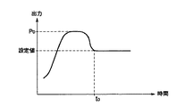
このような電気外科手術装置に於いては、出力スイツチをオンしてから実際に切開、凝固作用が現れるまでの時間(以下、立ち上がりという)を早くして、切れ味の向上、処置時間の短縮及び安全性を向上させている。すなわち、従来は、この立ち上がりを早くするために、図9に示されるように、出力スイッチをオンされた時刻から固定の遅延時間経過後の時刻t0 までに、設定値(例えぱ30W)より所定時間大きな電力、例えばP0 を供給し、時刻t0 以降に設定値の電力を供給するようにしている。
【0005】
【発明が解決しようとする課題】
ところで、電気外科手術装置に於いては、その用途に応じて処置具先端に設けられているアクティブ電極が、各種用意されている。図10は、こうしたアクティブ電極の例を示した図で、(a)はループ電極1、(b)はバンド電極2、(c)は溝付きローラ電極3である。
【0006】
こうした電極は、その形状によって体積が異なっているもので、したがって電気外科手術装置本体から同じ高周波電力を得ても、電極によって処置部の電流密度が異なる。すなわち、高周波電力を同一とした場合に、体積の小さいループ電極1が最も電流密度が高く(発熱しやすく)、次いでバンド電極2、そして溝付きローラ電極3の順になる。
【0007】
すると、図11に示されるように、高周波電力を同一とした場合、組織抵抗は図示aのループ電極、図示bのバンド電極、図示cの溝付きローラ電極と、電極の形状によって上昇の仕方が異なり、差が生じてしまう。このことは、上述したように、出力スイッチをオンした後の所定時間、設定値より大きな電力を供給して、立ち上がりを早くしようとしても、例えばループ電極1は十分に発熱して性能(組織変成等)が得られても、例えば溝付きローラ電極3では発熱しきらず、不十分な性能(組織変成等)になってしまう虞れがあった。
【0008】
この発明は上記実状に鑑みてなされたものであり、処置具の体積や表面積の異なる電極を使用しても、容易に且つ確実に、切開、凝固作用が現れるまでの立ち上がりを早くして、切れ味の向上、処置時間の短縮及び安全性を向上させることのできる電気外科手術装置を提供することを目的とする。
【0009】
【課題を解決するための手段】
すなわち、この発明は、生体組織に高周波電力を付与可能な電極と、上記生体組織を処置するための第1の高周波電力と、上記第1の高周波電力の供給前に上記第1の高周波電力よりも高く上記電極を加熱するための第2の高周波電力とを上記電極に供給可能な高周波電力供給手段と、使用する電極に応じて上記第2の高周波電力を供給する量を設定可変とする可変設定手段と、上記第1の高周波電力と、上記可変設定手段に応じて設定された上記第2の高周波電力を供給する上記高周波電力供給手段を制御する制御手段と、を具備することを特徴とする。
【0010】
またこの発明は、生体組織に高周波電力を付与可能な電極を有する処置手段と、上記処置手段を選択的に着脱可能なコネクタ手段を有する電源装置と、上記電源装置に設けられ、上記コネクタ手段に接続された上記電極の種別を判別する判別手段と、上記生体組織を処置するための第1の高周波電力と、上記第1の高周波電力の供給前に上記第1の高周波電力よりも高く上記電極を加熱するための第2の高周波電力とを上記電極に供給可能な高周波電力供給手段と、上記判別手段の判別結果に応じて上記第2の高周波電力を供給する量を設定可変とする可変設定手段と、上記第1の高周波電力と、上記可変設定手段に応じて設定された上記第2の高周波電力を供給する上記高周波電力供給手段を制御する制御手段と、を具備することを特徴とする。
この発明は、生体組織に高周波電力を付与可能な電極を有する処置手段と、上記生体組織を処置するための第1の高周波電力と、上記第1の高周波電力の供給前に上記第1の高周波電力よりも高く上記電極を加熱するための第2の高周波電力とを上記電極に供給する高周波電力供給手段と、上記高周波電力によって発生する上記生体組織の情報を判別する判別手段と、上記判別手段の判別結果に応じて上記第2の高周波電力を供給する量を設定可変とする可変設定手段と、上記第1の高周波電力と、上記可変設定手段に応じて設定された上記第2の高周波電力を制御する制御手段と、を具備することを特徴とする。
【0011】
更にこの発明は、生体組織に高周波電力を付与可能な電極と、上記生体組織を処置するための第1の高周波電力と、上記第1の高周波電力の供給前に上記第1の高周波電力よりも高く上記電極を加熱するための第2の高周波電力とを上記電極に供給可能な高周波電力供給手段と、使用する電極に応じて上記第2の高周波電力を供給する時間を設定可変とする可変設定手段と、上記第1の高周波電力と、上記可変設定手段に応じて設定された上記第2の高周波電力を供給する上記高周波電力供給手段を制御する制御手段と、を具備することを特徴とする。
この発明は、生体組織に高周波電力を付与可能な電極を有する処置手段と、上記処置手段を選択的に着脱可能なコネクタ手段を有する電源装置と、上記電源装置に設けられ、上記コネクタ手段に接続された上記電極の種別を判別する判別手段と、上記生体組織を処置するための第1の高周波電力と、上記第1の高周波電力の供給前に上記第1の高周波電力よりも高く上記電極を加熱するための第2の高周波電力とを上記電極に供給可能な高周波電力供給手段と、上記判別手段の判別結果に応じて上記第2の高周波電力を供給する時間を設定可変とする可変設定手段と、上記第1の高周波電力と、上記可変設定手段に応じて設定された上記第2の高周波電力を供給する上記高周波電力供給手段を制御する制御手段と、を具備することを特徴とする。
そして、この発明は、生体組織に高周波電力を付与可能な電極を有する処置手段と、上記生体組織を処置するための第1の高周波電力と、上記第1の高周波電力の供給前に上記第1の高周波電力よりも高く上記電極を加熱するための第2の高周波電力とを上記電極に供給する高周波電力供給手段と、上記高周波電力によって発生する上記生体組織の情報を判別する判別手段と、上記判別手段の判別結果に応じて上記第2の高周流電力を供給する時間を設定可変とする可変設定手段と、上記第1の高周波電力と、上記可変設定手段に応じて設定された上記第2の高周波電力を制御する制御手段と、を具備することを特徴とする。
【0012】
この発明の電気外科手術装置は、生体組織に高周波電力を付与可能な電極を有しており、上記生体組織を処置するための第1の高周波電力と、上記第1の高周波電力の供給前に上記第1の高周波電力よりも高く上記電極を加熱するための第2の高周波電力とが、高周波電力供給手段によって上記電極に供給される。そして、使用する電極に応じて上記第2の高周波電力を供給する量は可変設定手段で設定可変とされる。また、上記第1の高周波電力と、上記可変設定手段に応じて設定された上記第2の高周波電力とを供給する上記高周波電力供給手段が制御手段で制御される。
【0013】
またこの発明は、処置手段が生体組織に高周波電力を付与可能な電極を有し、電源装置が、上記処置手段を選択的に着脱可能なコネクタ手段を有している。そして、上記電源装置に設けられて、上記コネクタ手段に接続された上記電極の種別が判別手段で判別され、上記生体組織を処置するための第1の高周波電力と、上記第1の高周波電力の供給前に上記第1の高周波電力よりも高く上記電極を加熱するための第2の高周波電力とが、高周波電力供給手段によって上記電極に供給可能とされる。上記判別手段の判別結果に応じて、上記第2の高周波電力を供給する量が可変設定手段で設定可変とされる。また、上記第1の高周波電力と、上記可変設定手段に応じて設定された上記第2の高周波電力を供給する上記高周波電力供給手段が制御手段で制御される。
この発明の電気外科手術装置にあっては、処置手段が、生体組織に高周波電力を付与可能な電極を有しており、上記生体組織を処置するための第1の高周波電力と、上記第1の高周波電力の供給前に上記第1の高周波電力よりも高く上記電極を加熱するための第2の高周波電力とが、高周波電力供給手段によって上記電極に供給される。そして、上記高周波電力によって発生する上記生体組織の情報が判別手段で判別される。また、上記判別手段の判別結果に応じて上記第2の高周波電力を供給する量が、可変設定手段で設定可変とされる。上記第1の高周波電力と、上記可変設定手段に応じて設定された上記第2の高周波電力は、制御手段で制御される。
【0014】
更にこの発明の電気外科手術装置にあっては、生体組織に高周波電力を付与可能な電極を有しており、高周波電力供給手段によって、上記生体組織を処置するための第1の高周波電力と、上記第1の高周波電力の供給前に上記第1の高周波電力よりも高く上記電極を加熱するための第2の高周波電力とが、上記電極に供給可能とされる。また、使用する電極に応じて上記第2の高周波電力を供給する時間が可変設定手段で設定可変とされ、上記第1の高周波電力と、上記可変設定手段に応じて設定された上記第2の高周波電力を供給する上記高周波電力供給手段が制御手段によって制御される。
この発明の電気外科手術装置では、処置手段が、生体組織に高周波電力を付与可能な電極を有し、電源装置が、上記処置手段を選択的に着脱可能なコネクタ手段を有している。そして、上記電源装置に設けられ、上記コネクタ手段に接続された上記電極の種別は、判別手段により判別される。上記生体組織を処置するための第1の高周波電力と、上記第1の高周波電力の供給前に上記第1の高周波電力よりも高く上記電極を加熱するための第2の高周波電力とは、高周波電力供給手段により上記電極に供給可能とされる。また、上記判別手段の判別結果に応じて上記第2の高周波電力を供給する時間は、可変設定手段で設定可変とされる。そして、上記第1の高周波電力と、上記可変設定手段に応じて設定された上記第2の高周波電力を供給する上記高周波電力供給手段が、制御手段で制御される。
この発明の電気外科手術装置では、処理手段が、生体組織に高周波電力を付与可能な電極を有しており、上記生体組織を処置するための第1の高周波電力と、上記第1の高周波電力の供給前に上記第1の高周波電力よりも高く上記電極を加熱するための第2の高周波電力とが、高周波電力供給手段によって上記電極に供給される。上記高周波電力によって発生する上記生体組織の情報は判別手段で判別され、上記判別手段の判別結果に応じて上記第2の高周流電力を供給する時間は可変設定手段で設定可変とされる。そして、上記第1の高周波電力と、上記可変設定手段に応じて設定された上記第2の高周波電力は、制御手段により制御される。
【0015】
【発明の実施の形態】
以下、図面を参照してこの発明の実施の形態を説明する。
図2は、この発明の第1の実施の形態に係る電気外科手術装置の概略構成を示した図である。
【0016】
図2に於いて、この電気外科手術装置10は、高周波電力を発生する高周波焼灼電源装置11と、アクティブラインのコード12を介して接続されて患者14の処置部位に処置を施す処置用のアクティブ電極を有したモノポーラ処置具13と、患者14の体表面上に接触させるもので帰還用のコード16に接続された帰還電極15と、フットスイッチ17とにより構成される。
【0017】
このような構成に於いて、フットスイッチ17のオンによって高周波焼灼電源装置11が起動される。そして、高周波焼灼電源装置11によってエネルギー源である高周波電力が発生され、モノポーラ処置具13のアクティブ電極を患者14の処置部位に接触させて生体組織に集中的に高周波電流が流入される。そして、帰還電極15より高周波電流が分散して回収されることによって、上記処置部位の切除、凝固等の処置が行われるようになっている。
【0018】
尚、ここでは図示されていないが、フットスイッチ17の代わりにモノポーラ処置具13に同様のスイッチを設けても良い。
図1(a)は、上記高周波焼灼電源装置11の内部構成を示した図である。
【0019】
図1(a)に於いて、商用電源21には、所望の供給電圧を供給するための電源回路22が接続されている。そして、この電源回路22には、操作内容による出力モードに対応した波形を発生させるための波形発生回路23と、高周波焼灼電源装置11の装置全体を制御するCPU24とが接続されている。これら波形発生回路23及びCPU24には、CPU24からのデジタル信号をアナログ信号に変換してアンプ26を制御するためのD/Aコンバータ25と、波形発生回路23により得られた微小な信号を増幅するためのアンプ26とが接続される。
【0020】
出力トランス27は、その1次側がコンデンサを介してアンプ26に接続され、2次側がコンデンサと、電圧センサ28及び電流センサ29を介して端子11a、11bに接続される。上記電圧センサ28及び電流センサ29で検知された信号は、A/Dコンバータ30によってデジタル信号に変換されてCPU24に出力される。また、上記CPU24には、表示部31が接続されている。
【0021】
端子11aには、アクティブラインを介してモノポーラ処置具13a、そしてモノポーラ電極13bが接続されている。一方、端子11bには帰還用のラインを介して帰還電極15が接続される。
【0022】
尚、図1(a)では、処置具としてモノポーラ処置具を示しているが、図1(b)に示されるようなバイポーラ処置具32a及びバイポーラ電極32bを用いても良い。この場合、帰還電極15は不要となる。
【0023】
ここで、従来の技術でも述べたように、処置具の電極は、その形状によって同じ高周波電力を得ても電流密度が異なる。したがって、それぞれの電極で十分な性能を得るためには、例えば、体積の小さいループ電極に対して、体積の大きい、すなわち発熱し難いバンド電極や溝付きローラ電極を十分に発熱するようにすれば良い。
【0024】
このような性能を得るためには、電極の形状によらず、処置具の発熱量を一定にする必要がある。つまり、出力スイッチをオンして、生体の組織と上記電極との接触を検知してから規定時間、規定出力だけ設定出力より大きな高周波出力(以下、初期出力と記す)を得るにあたり、ループ電極に対してバンド電極、更には溝付きローラ電極の初期出力を高めに設定する。或いは、上記初期出力の継続時間を、ループ電極に対してバンド電極、更には溝付きローラ電極の場合、長めに設定する。
【0025】
例えば、初期出力を設定する場合、ループ電極の初期出力は設定出力の1.5倍、バンド電極の初期出力は設定出力の2倍、溝付きローラ電極の初期出力は設定出力の3倍に設定する。また、初期出力の継続時間を設定する場合は、ループ電極の継続時間は10ms、バンド電極の継続時間は20ms、そして溝付きローラ電極の継続時間は30msに設定する。
【0026】
次に、こうした処置具の熱容量設定の具体例について説明する。
図3は、高周波焼灼電源装置11のフロントパネルに設けられた表示部の例を示した図である。
【0027】
図3に於いて、高周波焼灼電源装置11のフロントパネルには、設定出力より高い立ち上がり時の出力値、すなわち初期出力の数値を示す出力表示部41aと、この初期出力を継続する時間を表す時間表示部41bが設けられている。また、これら出力表示部41a、時間表示部41bの下方には、予め使用者が出力値、時間を設定するための設定釦42a、42bが設けられている。
【0028】
使用者は、モノポーラ電極として使用する電極の形状に応じて、設定釦42a、42bを操作して、初期出力の数値、若しくは初期出力の継続時間を設定する。例えば、ループ電極に比べて、バンド電極、溝付きローラ電極の出力値を高く設定する。或いはループ電極に比べて、バンド電極、溝付きローラ電極の出力する時間を長く設定する。
【0029】
このように設定することにより、処置具にどの形状の電極を使用しても、十分に発熱して良好な性能を得ることができる。
図4は、高周波焼灼電源装置11のフロントパネルに設けられた表示部の別の例を示した図である。
【0030】
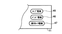
図4に於いて、高周波焼灼電源装置11のフロントパネルには、ループ電極選択釦45、バンド電極選択釦46、溝付きローラ電極選択釦47が設けられている。これらの選択釦45、46、47は、それぞれの電極の形状に応じた立ち上がり時の出力、または立ち上がり時の出力継続時間が選択可能になっている。
【0031】
すなわち、使用者は、モノポーラ電極として使用する電極の形状に応じて、ループ電極選択釦45、バンド電極選択釦46、溝付きローラ電極選択釦47の何れかの選択釦を押下する。これにより、例えば、ループ電極選択釦45が操作される場合に比べて、バンド電極選択釦46、溝付きローラ電極選択釦47が操作されたときの方が、立ち上がり時の初期出力の値が高く設定される、或いは初期出力の継続時間が長く設定される。
【0032】
このように設定することにより、処置具にどの形状の電極を使用しても、十分に発熱して良好な性能を得ることができる。尚、出力値と時間の設定を組合わせ、出力値を高く、且つ出力する時間を長く設定するようにしても良い。
【0033】
また、図3及び図4の例では、使用者が操作パネルを操作して初期出力または初期出力の継続時間を設定するようにしていたが、これに限られるものではない。例えば、処置具のコネクタに電極を自動判別するための手段を設けるようにしても良い。
【0034】
図5は、モノポーラ電極の形状を検知するためのコネクタの構造例を示した図である。
図5に於いて、このコネクタ35は、アクティブライン36と、抵抗により互いに接続された識別ピン37a及び37bより成る。このコネクタ35を、例えば高周波焼灼電源装置11の本体に接続すると、本体から識別ピン37a及び37bに検知電流が流れる。そして、識別ピン37a、37bの両端に発生する電圧によって、接続されている処置具の電極がループ電極か、バンド電極か、或いは溝付きローラ電極であるかが判別される。
【0035】
このように構成することにより、処置具の電極の種別を自動的に判別して、各電極に最適の初期出力の値、継続時間を自動設定することができ、何れの電極を使用しても良好な性能を得ることができる。
【0036】
図6は、上述した第1の実施の形態の動作を説明するフローチャートである。先ず、ステップS1に於いて、高周波出力のスイッチ、すなわちフットスイッチ17がオンされたか否かが判別される。ここで、フットスイッチ17がオンされていれば、続くステップS2にて、処置具の電極が生体の組織と接触したか否かが判別される。ここでは、電圧センサ28または電流センサ29によって、上記電極が組織と接触しているか否かが判別される。
【0037】
ここで、電極が組織と接触している場合は、ステップS3に進んで初期出力が設定される。この初期出力は、立ち上がり時に設定出力より大きく出力される高周波出力である。次いで、ステップS4にて、組織情報が取込まれる。この組織情報とは、負荷にかかっている電圧や組織のインピーダンス、組織に流れている電流等であり、電圧センサ28、電流センサ29等によって取込まれる。
【0038】
そして、ステップS5に於いて、上記取込まれた組織情報が規定値以上であるか否かが判別される。ここで、規定値に達しない場合は上記ステップS3に戻り、以降の処理が繰り返される。一方、ステップS5にて規定値以上になったならば、ステップS6に進んで設定出力に減少される。
【0039】
次に、この発明の第2の実施の形態を説明する。
図7(a)は組織抵抗若しくは電圧の経時変化を表した特性図、(b)は処置具の実際の出力の経時変化を表した特性図である。
【0040】
いま、出力スイッチがオンされて高周波出力が上昇し、予め設定された初期出力値P1 に到達すると、組織抵抗及び電圧が上昇する。そして、電圧センサ28のモニタにより、予め設定された抵抗値Z1 及び電圧値V1 になったことが検知されると、その時点(時刻t1 )で処置具は安定した切除が可能になる。この切除可能時刻t1 を経過したならば、処置具の出力は初期出力値P1 から通常の設定値に減少される。
【0041】
このように、出力スイッチのオンから予め設定された抵抗値Z1 及び電圧値V1 に至る時刻t1 までの時間を判断することにより、処置具の電極を判別することができる。すなわち、発熱しにくい電極の場合は、上記設定された抵抗値Z1 及び電圧値V1 に到達するのに時間を要する。したがって、上記Z1 、V1 に到達する切除可能時間t1 を比較すれば、電極の種別がわかる。例えば、この時間t1 の早い順に、ループ電極、バンド電極、溝付きローラ電極となる。
【0042】
次に、この発明の第3の実施の形態を説明する。
上述した第2の実施の形態は、切除可能時間を予め設定された組織抵抗値及び電圧値という絶対値で検知していた。これに対し、第3の実施の形態は組織抵抗及び電圧の変化率を検知するようにする。
【0043】
図8(a)は組織抵抗若しくは電圧の変化率を表した特性図、(b)は処置具の実際の出力の経時変化を表した特性図である。
いま、出力スイッチがオンされて高周波出力が上昇し、予め設定された初期出力値P1 に到達すると、組織抵抗及び電圧が上昇する。そして、予め設定された抵抗及び電圧の変化率ΔV1 及びΔZ1 になったことが検知されると、その時点(時刻t1 )で処置具は安定した切除が可能になる。この切除可能時刻t1 を経過したならば、処置具の出力は初期出力値P1 から通常の設定値に減少される。
【0044】
このように第3の実施の形態によれば、第2の実施の形態と同様に、出力スイッチのオンから予め設定された抵抗及び電圧の変化率ΔZ1 及びΔV1 に至る時刻t1 までの時間を判断することにより、処置具の電極を判別することができる。
【0045】
尚、この発明の上記実施態様によれば、以下の如き構成を得ることができる。
(1) 生体と接触して処置を施す処置手段と、この処置手段が上記生体と接触したことを検出する検出手段と、この検出手段で検出された信号に基いて所定の値で高周波出力を供給する第1の出力手段と、立ち上がり時の初期期間に上記所定の値より高い初期設定値で高周波出力を供給する第2の出力手段とを備える電気外科手術装置に於いて、
上記第2の出力手段は、上記初期期間及び上記初期設定値のうち、少なくとも1つを設定変更可能なことを特徴とする電気外科手術装置。
【0046】
(2) 上記検出手段は、出力電流、電圧のうち少なくとも1つ以上のパラメータの演算を基に検出を行うことを特徴とする上記(1)に記載の電気外科手術装置。
【0047】
(3) 生体と接触して処置を施すもので交換可能な処置手段と、この処置手段が上記生体と接触したことを検出する検出手段と、この検出手段で検出された信号に基いて所定の値で高周波出力を供給する第1の出力手段と、立ち上がり時の初期期間に上記所定の値より高い初期設定値で高周波出力を供給する第2の出力手段とを備える電気外科手術装置に於いて、
上記第2の出力手段は、上記交換可能な処置手段の種別に応じて、上記初期期間及び/または上記初期設定値を選択可能であることを特徴とする電気外科手術装置。
【0048】
(4) 上記検出手段は、出力電流、電圧のうち少なくとも1つ以上のパラメータの演算を基に検出を行うことを特徴とする上記(3)に記載の電気外科手術装置。
【0049】
(5) 上記検出手段は、上記生体の組織インピーダンス、抵抗のうち少なくとも1つ以上のパラメータの演算を基に検出を行うことを特徴とする上記(3)に記載の電気外科手術装置。
【0050】
(6) 交換可能な処置具の電極が生体の組織と接触したかを判別する第1の手段と、
この第1の手段で上記処置具の電極が生体の組織と接触したと判別された場合に立ち上がり時の規定時間、所定の設定出力より大きい初期出力を設定する第2の手段と、
上記生体の組織の情報を取込む第3の手段と、
この第3の手段で取込まれた組織の情報が規定値以上であるかを判別する第4の手段と、
この第4の手段により上記組織の情報が上記規定値以上であると判別された場合に上記初期出力を上記所定の設定出力に変更する第5の手段と
を具備することを特徴とする電気外科手術装置。
【0051】
(7) 上記交換可能な処置具電極の種別を判別する第5の手段を更に具備し、上記第4の手段はこの第5の手段の判別結果に基いて上記規定値を変更することを特徴とする上記(6)に記載の電気外科手術装置。
【0052】
(8) 上記第5の手段は、出力電流、電圧のうち少なくとも1つ以上のパラメータの演算を基に判別を行うことを特徴とする上記(7)に記載の電気外科手術装置。
【0053】
(9) 上記第5の手段は、上記生体の組織インピーダンス、抵抗のうち少なくとも1つ以上のパラメータの演算を基に判別を行うことを特徴とする上記(7)に記載の電気外科手術装置。
【0054】
【発明の効果】
以上のようにこの発明によれば、処置具の体積や表面積の異なる電極を使用しても、容易に且つ確実に、切開、凝固作用が現れるまでの立ち上がりを早くして、切れ味の向上、処置時間の短縮及び安全性を向上させることのできる電気外科手術装置を提供することができる。
【図面の簡単な説明】
【図1】(a)は高周波焼灼電源装置の内部構成を示した図、(b)はバイポーラ処置具の構成を示した図である。
【図2】この発明の第1の実施の形態に係る電気外科手術装置の概略構成を示した図である。
【図3】高周波焼灼電源装置11のフロントパネルに設けられた表示部の例を示した図である。
【図4】高周波焼灼電源装置11のフロントパネルに設けられた表示部の別の例を示した図である。
【図5】モノポーラ電極の形状を検知するためのコネクタの構造例を示した図である。
【図6】第1の実施の形態の動作を説明するフローチャートである。
【図7】この発明の第2の実施の形態を説明するもので、(a)は組織抵抗若しくは電圧の経時変化を表した特性図、(b)は処置具の実際の出力の経時変化を表した特性図である。
【図8】この発明の第3の実施の形態を説明するもので、(a)は組織抵抗若しくは電圧の変化率を表した特性図、(b)は処置具の実際の出力の経時変化を表した特性図である。
【図9】従来の電気外科手術装置の作用を説明する図である。
【図10】アクティブ電極の例を示したもので、(a)はループ電極、(b)はバンド電極、(c)は溝付きローラ電極の構造を示した図である。
【図11】電気外科手術装置の電極の形状と組織抵抗との関係を示した図である。
【符号の説明】
1 ループ電極、
2 バンド電極、
3 溝付きローラ電極、
10 電気外科手術装置、
11 高周波焼灼電源装置、
12 アクティブラインのコード、
13、13a モノポーラ処置具、
13b モノポーラ電極、
14 患者、
15 帰還電極、
16 帰還用のコード、
17 フットスイッチ、
21 商用電源、
22 電源回路、
23 波形発生回路、
24 CPU、
25 D/Aコンバータ、
26 アンプ、
27 出力トランス、
28 電圧センサ、
28 電流センサ、
30 A/Dコンバータ、
31 表示部、
35 コネクタ、
36 アクティブライン、
37a、37b 識別ピン、
41a 出力表示部、
41b 時間表示部、
42a、42b 設定釦、
45 ループ電極選択釦、
46 バンド電極選択釦、
47 溝付きローラ電極選択釦。[0001]
TECHNICAL FIELD OF THE INVENTION
The present invention relates to an electrosurgical apparatus, and more particularly, to an electrosurgical apparatus that applies a high-frequency current to a living tissue and performs treatment such as excision and coagulation of the living tissue by heat generated by the high-frequency current.
[0002]
[Prior art]
2. Description of the Related Art An electrosurgical apparatus performs a treatment such as excision and coagulation of a living tissue by flowing a high-frequency current through the living tissue, and is used for general surgery and the like. Such an electrosurgical apparatus includes an electrosurgical apparatus main body, a treatment tool having an active electrode, and a return electrode that comes into contact with the patient's body surface.
[0003]
The high frequency power is generated by the main body of the electrosurgical surgical apparatus, the active electrode is brought into contact with the treatment site, the high frequency current is intensively introduced into the living tissue, and the high frequency current is dispersed and collected from the return electrode. Procedures such as tissue excision and coagulation can be performed.
[0004]
In such an electrosurgical apparatus, the time from when the output switch is turned on to when the incision and coagulation action actually appear (hereinafter referred to as "rise") is shortened, thereby improving sharpness, shortening the treatment time, and Improves safety. That is, conventionally, in order to make this rise earlier, as shown in FIG. 9, a time t after a fixed delay time elapses from the time when the output switch is turned on.0 By the time, the power that is larger than the set value (eg, 30 W) for a predetermined time, for example, P0 At time t0 Thereafter, the power of the set value is supplied.
[0005]
[Problems to be solved by the invention]
By the way, in the electrosurgical apparatus, various active electrodes provided at the distal end of the treatment tool are prepared according to the use. FIGS. 10A and 10B show examples of such active electrodes. FIG. 10A shows a
[0006]
These electrodes have different volumes depending on their shapes. Therefore, even if the same high-frequency power is obtained from the electrosurgical apparatus main body, the current density of the treatment portion differs depending on the electrodes. That is, when the high-frequency power is the same, the
[0007]
Then, as shown in FIG. 11, when the high-frequency power is the same, the manner of increasing the tissue resistance depends on the loop electrode shown in FIG. A, the band electrode shown in FIG. B, the grooved roller electrode shown in FIG. Differently, there is a difference. This means that, as described above, even if the power is supplied for a predetermined time after the output switch is turned on and the power is larger than the set value and the rise is to be accelerated, for example, the
[0008]
The present invention has been made in view of the above circumstances, and even when electrodes having different volumes and surface areas of a treatment tool are used, the incision and the start up to the appearance of the coagulation action are quickly and easily performed, and the sharpness is improved. It is an object of the present invention to provide an electrosurgical apparatus capable of improving the performance, shortening the treatment time, and improving safety.
[0009]
[Means for Solving the Problems]
That is, the present invention provides an electric power that can apply high-frequency electric power to living tissue.Poles,Treating the above living tissueA first high frequency power forHeating the electrode higher than the first high-frequency power before supplying the first high-frequency powerAnd a second high frequency power forTo serveHigh-frequency power supply means that can be supplied;Depending on the electrode used, the secondHigh frequency powerVariable supply amountVariable setting means,The first high-frequency power,The above variable setting meansDepending onSet the above2High frequency powerSupplyControl means for controlling the high-frequency power supply means.
[0010]
The present invention also provides an electrode capable of applying high-frequency power to living tissue.HavingThe treatment means and the treatment means are selectively attached and detachedPossiblePower supply device having a connector means, provided in the power supply device,The above connected to the connector meansDetermining means for determining the type of the electrode;A first high-frequency power for treating the living tissue and a second high-frequency power for heating the electrode higher than the first high-frequency power before the supply of the first high-frequency power; High-frequency power supply means that can be supplied toIn the judgment result of the above judgment meansThe amount of the second high frequency power to be suppliedConfigurationVariableVariable setting means,The first high-frequency power,The above variable setting meansSet accordinglyThe second high frequency powerSupplyControl means for controlling the high-frequency power supply means.
The present invention provides a treatment unit having an electrode capable of applying high-frequency power to living tissue,Treat the above living tissueA first high-frequency power for performingHeating the electrode higher than the first high-frequency power before supplying the first high-frequency powerAnd a second high frequency power forTo serveSalaryDoHigh frequency power supply means,Determining means for determining information on the living tissue generated by the high-frequency power; andThe above2High frequency powerSupply amountConfigurationVariableVariable setting meansAnd the first high-frequency power,The above variable setting meansDepending onSet the above2High frequency powerToAnd control means for controlling.
[0011]
Further, the present inventionAn electrode capable of applying high-frequency power to living tissue, a first high-frequency power for treating the living tissue, and heating the electrode higher than the first high-frequency power before supplying the first high-frequency power in order toSecond high frequency powerAndThe above electrodeTo serveHigh-frequency power supply means that can be supplied;Variable setting means for setting and varying the time for supplying the second high-frequency power according to the electrode to be used; and the first high-frequency power and the variable setting means according to the variable setting means.SetSupplying the second high frequency powerControl means for controlling the high-frequency power supply means.
The present inventionHas electrodes that can apply high-frequency power to living tissueThe treatment means and the treatment means are selectively attached and detachedPossiblePower supply device having a simple connector means,Provided in the power supply device,Connected to the connector meansthe aboveDetermining means for determining the type of the electrode;A first high-frequency power for treating the living tissue and a first high-frequency power for heating the electrode higher than the first high-frequency power before the first high-frequency power is supplied;No.2The high frequency power and the above electrodeTo serveHigh-frequency power supply means that can be supplied;Variable setting means for setting and varying the time for supplying the second high-frequency power according to the determination result of the determination means, the first high-frequency power, and the second high-frequency power set according to the variable setting means. Supply high frequency powerControl means for controlling the high-frequency power supply means.
Then, the present invention provides a treatment means having an electrode capable of applying high-frequency power to a living tissue, a first high-frequency power for treating the living tissue, and a first high-frequency power before supplying the first high-frequency power. A high-frequency power supply unit for supplying the second high-frequency power for heating the electrode higher than the high-frequency power to the electrode; a determination unit for determining information on the living tissue generated by the high-frequency power; Variable setting means for setting and varying the time for supplying the second high peripheral power in accordance with the result of the determination by the determination means; the first high-frequency power; and the first high-frequency power set in accordance with the variable setting means. And control means for controlling the high-frequency power.
[0012]
Electrosurgical device of the present inventionIs rawIt has electrodes that can apply high-frequency power to body tissue,Treating the above living tissueA first high frequency power forHeating the electrode higher than the first high-frequency power before supplying the first high-frequency powerAnd a second high-frequency power for supplying power to the electrode by the high-frequency power supply means.To serveBe paid.Then, depending on the electrode used, the secondHigh frequency powerThe amount of supply is made variable by variable setting means. Also,The first high-frequency power,The above variable setting meansDepending onSet the above2High frequency powerAnd supplyThe high-frequency power supply unit is controlled by the control unit.
[0013]
The invention also providesTreatment meansElectrodes that can apply high-frequency power to living tissueAnd the power supply hasSelectable attachment / detachment of the above treatment meansPossibleIt has a simple connector means. And the aboveThe power supply unit is provided with the connector means connected to the connector means.The type of the electrode is determined by the determination means,The first high-frequency power for treating the living tissue and the second high-frequency power for heating the electrode higher than the first high-frequency power before the supply of the first high-frequency power are high-frequency. The power can be supplied to the electrodes by power supply means.In the judgment result of the above judgment meansAccordingly, the amount of supplying the second high frequency power isWith variable setting meansVariable settings andIs done. Also,The first high-frequency power,The above variable setting meansSet accordinglyThe second high frequency powerSupplyThe high-frequency power supply unit is controlled by the control unit.
In the electrosurgical apparatus according to the present invention, the treatment means has an electrode capable of applying high-frequency power to the living tissue,Treat the above living tissueA first high-frequency power for performingHeating the electrode higher than the first high-frequency power before supplying the first high-frequency powerAnd a second high-frequency power for supplying power to the electrode by the high-frequency power supply means.To servePaidYou. SoAnd the high frequency powerCaused byThe information on the living tissue is determined by the determination unit. Also,The amount of supplying the second high-frequency power according to the determination result of the determination means is:Variable setting meansThe setting is variable. The first high-frequency power and the second high-frequency power set according to the variable setting means are controlled by control means.
[0014]
Further, in the electrosurgical apparatus according to the present invention,A first high-frequency power for treating the living tissue by the high-frequency power supply means, and the first high-frequency power before the first high-frequency power is supplied. To heat the electrodes above the powerSecond high frequency powerAndThe above electrodeCan be supplied. Further, the time for supplying the second high-frequency power is variable according to the electrode to be used by the variable setting means, and the time for supplying the second high-frequency power is variable according to the first high-frequency power and the variable setting means.SetSupplying the second high frequency powerThe high frequency power supply unit is controlled by the control unit.
In the electrosurgical apparatus according to the present invention, the treatment means includes:Having an electrode capable of applying high-frequency power to living tissue,Power supplyBut,Selectable attachment / detachment of the above treatment meansPossibleIt has a simple connector means. AndProvided in the power supply device,Connected to the connector meansthe aboveThe type of the electrode is determined by the determination unit.A first high-frequency power for treating the living tissue and a first high-frequency power for heating the electrode higher than the first high-frequency power before the first high-frequency power is supplied;No.2High-frequency power means high-frequency power supply meansByThe above electrodeTo serveIt can be paid.The time for supplying the second high-frequency power according to the result of the determination by the determining means is variable by the variable setting means. And supplying the first high-frequency power and the second high-frequency power set according to the variable setting means.The high frequency power supply unit is controlled by the control unit.
In the electrosurgical apparatus according to the present invention, the processing means has an electrode capable of applying high-frequency power to the living tissue, the first high-frequency power for treating the living tissue, and the first high-frequency power. And a second high-frequency power for heating the electrode higher than the first high-frequency power before the supply of the first high-frequency power is supplied to the electrode by high-frequency power supply means. The information on the living tissue generated by the high-frequency power is determined by a determining unit, and the time for supplying the second high-circulating-current power is set variable by a variable setting unit according to the determination result of the determining unit. Then, the first high-frequency power and the second high-frequency power set according to the variable setting means are controlled by control means.
[0015]
BEST MODE FOR CARRYING OUT THE INVENTION
Hereinafter, embodiments of the present invention will be described with reference to the drawings.
FIG. 2 is a diagram showing a schematic configuration of the electrosurgical operation apparatus according to the first embodiment of the present invention.
[0016]
In FIG. 2, an
[0017]
In such a configuration, the high-frequency ablation
[0018]
Although not shown here, a similar switch may be provided on the
FIG. 1A is a diagram showing an internal configuration of the high-frequency ablation
[0019]
In FIG. 1A, a
[0020]
The
[0021]
A
[0022]
Although FIG. 1A shows a monopolar treatment tool as a treatment tool, a
[0023]
Here, as described in the related art, the electrodes of the treatment tool have different current densities depending on their shapes, even if the same high-frequency power is obtained. Therefore, in order to obtain sufficient performance with each electrode, for example, for a loop electrode having a small volume, a large volume, that is, a band electrode or a grooved roller electrode that is difficult to generate heat should be sufficiently heated. good.
[0024]
In order to obtain such performance, it is necessary to make the calorific value of the treatment tool constant regardless of the shape of the electrode. In other words, when the output switch is turned on and the contact between the living body tissue and the electrode is detected, a high-frequency output (hereinafter, referred to as an initial output) larger than the set output for a specified time for a specified time is obtained. On the other hand, the initial output of the band electrode and the grooved roller electrode is set higher. Alternatively, the duration of the initial output is set to be longer for the band electrode and the grooved roller electrode with respect to the loop electrode.
[0025]
For example, when setting the initial output, the initial output of the loop electrode is set to 1.5 times the set output, the initial output of the band electrode is set to 2 times the set output, and the initial output of the grooved roller electrode is set to 3 times the set output. I do. When the duration of the initial output is set, the duration of the loop electrode is set to 10 ms, the duration of the band electrode is set to 20 ms, and the duration of the grooved roller electrode is set to 30 ms.
[0026]
Next, a specific example of setting the heat capacity of the treatment tool will be described.
FIG. 3 is a diagram illustrating an example of a display unit provided on the front panel of the high-frequency ablation
[0027]
In FIG. 3, on the front panel of the high-frequency ablation power supply 11IsHigher than constant powerAt the time of risingAn
[0028]
The user operates the setting
[0029]
By setting in this manner, sufficient heat is generated and good performance can be obtained regardless of the shape of the electrode used for the treatment tool.
FIG. 4 is a diagram illustrating another example of the display unit provided on the front panel of the high-frequency ablation
[0030]
In FIG. 4, a loop
[0031]
That is, the user presses any one of the loop
[0032]
By setting in this manner, sufficient heat is generated and good performance can be obtained regardless of the shape of the electrode used for the treatment tool. The output value and the time setting may be combined to set the output value to be high and the output time to be long.
[0033]
In the examples of FIGS. 3 and 4, the user operates the operation panel to set the initial output or the duration of the initial output. However, the present invention is not limited to this. For example, the connector of the treatment tool may be provided with a means for automatically determining the electrode.
[0034]
FIG. 5 is a diagram showing a structural example of a connector for detecting the shape of a monopolar electrode.
In FIG. 5, the connector 35 includes an active line 36 and identification pins 37a and 37b connected to each other by a resistor. When the connector 35 is connected to, for example, the main body of the high-frequency ablation
[0035]
With this configuration, the type of the electrode of the treatment tool can be automatically determined, and the optimal initial output value and duration for each electrode can be automatically set. Good performance can be obtained.
[0036]
FIG. 6 is a flowchart illustrating the operation of the above-described first embodiment. First, in step S1, it is determined whether or not the switch for high-frequency output, that is, the
[0037]
Here, when the electrode is in contact with the tissue, the process proceeds to step S3, and the initial output is set. This initial output isSet inThis is a high-frequency output that is greater than the constant output. Next, in step S4, organization information is acquired. The tissue information is the voltage applied to the load, the impedance of the tissue, the current flowing through the tissue, and the like, and is captured by the
[0038]
Then, in step S5, it is determined whether or not the acquired organization information is equal to or greater than a specified value. Here, if the specified value is not reached, the process returns to step S3, and the subsequent processing is repeated. On the other hand, if the value exceeds the specified value in step S5, the process proceeds to step S6, and the output is reduced to the set value.
[0039]
Next, a second embodiment of the present invention will be described.
FIG. 7A is a characteristic diagram showing a temporal change of a tissue resistance or a voltage, and FIG. 7B is a characteristic diagram showing a temporal change of an actual output of the treatment tool.
[0040]
Now, the output switch is turned on, the high frequency output rises, and the preset initial output value P1 , The tissue resistance and voltage increase. The resistance value Z set in advance by the monitor of the
[0041]
As described above, the resistance value Z set in advance after the output switch is turned on.1 And voltage value V1 Time t leading to1 By judging the time until, the electrode of the treatment tool can be determined. That is, in the case of an electrode that does not easily generate heat, the resistance Z1 And voltage value V1 Takes time to reach. Therefore, the above Z1 , V1 Time to reach t1 By comparison, the type of the electrode is known. For example, this time t1 , The loop electrode, the band electrode, and the grooved roller electrode in that order.
[0042]
Next, a third embodiment of the present invention will be described.
In the above-described second embodiment, the resectable time is detected by absolute values of a preset tissue resistance value and voltage value. On the other hand, the third embodiment detects the tissue resistance and the rate of change in voltage.
[0043]
FIG. 8A is a characteristic diagram showing a change rate of a tissue resistance or a voltage, and FIG. 8B is a characteristic diagram showing a temporal change of an actual output of the treatment tool.
Now, the output switch is turned on, the high frequency output rises, and the preset initial output value P1 , The tissue resistance and voltage increase. Then, a predetermined resistance and voltage change rate ΔV1 And ΔZ1 Is detected (at time t).1 ) Enables stable resection of the treatment tool. This cuttable time t1 Has passed, the output of the treatment instrument is the initial output value P1 To the normal set value.
[0044]
As described above, according to the third embodiment, similarly to the second embodiment, the preset change rate ΔZ of the resistance and the voltage from when the output switch is turned on.1 And ΔV1 Time t leading to1 By judging the time until, the electrode of the treatment tool can be determined.
[0045]
According to the above embodiment of the present invention, the following configuration can be obtained.
(1) Treatment means for performing a treatment by contacting a living body, detection means for detecting that the treatment means has contacted the living body, and high-frequency output at a predetermined value based on a signal detected by the detection means. An electrosurgical apparatus comprising: a first output means for supplying; and a second output means for supplying a high-frequency output at an initial setting value higher than the predetermined value in an initial period at the time of rising.
The electrosurgical apparatus according to
[0046]
(2) The electrosurgical apparatus according to (1), wherein the detection unit performs detection based on calculation of at least one parameter of an output current and a voltage.
[0047]
(3) Replaceable treatment means for performing treatment in contact with a living body, detection means for detecting that the treatment means has contacted the living body, and a predetermined means based on a signal detected by the detection means. An electrosurgical apparatus comprising: first output means for supplying a high-frequency output at a value; and second output means for supplying a high-frequency output at an initial value higher than the predetermined value during an initial period at the time of rising. ,
An electrosurgical apparatus according to
[0048]
(4) The electrosurgical apparatus according to (3), wherein the detection means performs detection based on calculation of at least one parameter of output current and voltage.
[0049]
(5) The electrosurgical apparatus according to (3), wherein the detection unit performs the detection based on calculation of at least one parameter of tissue impedance and resistance of the living body.
[0050]
(6) first means for determining whether or not the electrode of the exchangeable treatment tool has come into contact with the tissue of a living body;
A second means for setting an initial output greater than a predetermined set output when the first means determines that the electrode of the treatment tool has come into contact with the tissue of a living body,
Third means for capturing information on the tissue of the living body;
A fourth means for determining whether or not the information of the organization captured by the third means is equal to or greater than a prescribed value;
A fifth means for changing the initial output to the predetermined setting output when the information of the organization is determined to be equal to or more than the specified value by the fourth means;
An electrosurgical device, comprising:
[0051]
(7) A fifth means for judging the type of the replaceable treatment instrument electrode, wherein the fourth means changes the specified value based on the judgment result of the fifth means. The electrosurgical apparatus according to the above (6).
[0052]
(8) The electrosurgical apparatus according to (7), wherein the fifth means performs the determination based on the calculation of at least one parameter of the output current and the voltage.
[0053]
(9) The electrosurgical apparatus according to (7), wherein the fifth means performs the determination based on calculation of at least one parameter of the tissue impedance and the resistance of the living body.
[0054]
【The invention's effect】
As described above, according to the present invention, even if electrodes having different volumes and surface areas of the treatment tool are used, the incision and the rise until the coagulation action appears can be quickly and easily performed to improve sharpness and treatment. An electrosurgical apparatus capable of reducing time and improving safety can be provided.
[Brief description of the drawings]
1A is a diagram showing an internal configuration of a high-frequency ablation power supply device, and FIG. 1B is a diagram showing a configuration of a bipolar treatment tool.
FIG. 2 is a diagram showing a schematic configuration of an electrosurgical operation apparatus according to the first embodiment of the present invention.
FIG. 3 is a diagram showing an example of a display unit provided on a front panel of the high-frequency ablation
FIG. 4 is a diagram showing another example of the display unit provided on the front panel of the high-frequency ablation
FIG. 5 is a diagram showing a structural example of a connector for detecting the shape of a monopolar electrode.
FIG. 6 is a flowchart illustrating the operation of the first embodiment.
FIGS. 7A and 7B are diagrams illustrating a second embodiment of the present invention, in which FIG. 7A is a characteristic diagram showing a temporal change in tissue resistance or voltage, and FIG. FIG. 4 is a characteristic diagram shown.
FIGS. 8A and 8B are diagrams illustrating a third embodiment of the present invention, in which FIG. 8A is a characteristic diagram showing a tissue resistance or a change rate of voltage, and FIG. FIG. 4 is a characteristic diagram shown.
FIG. 9 is a diagram illustrating the operation of a conventional electrosurgical apparatus.
FIGS. 10A and 10B show examples of active electrodes, in which FIG. 10A shows the structure of a loop electrode, FIG. 10B shows the structure of a band electrode, and FIG. 10C shows the structure of a grooved roller electrode.
FIG. 11 is a diagram showing a relationship between the shape of an electrode of an electrosurgical operation apparatus and tissue resistance.
[Explanation of symbols]
1 loop electrode,
2 band electrode,
3 grooved roller electrode,
10 electrosurgical devices,
11 high frequency ablation power supply,
12 Active line code,
13, 13a monopolar treatment tool,
13b monopolar electrode,
14 patients,
15 return electrode,
16 Return code,
17 foot switch,
21 commercial power,
22 power supply circuit,
23 waveform generation circuit,
24 CPU,
25 D / A converter,
26 amplifiers,
27 output transformer,
28 voltage sensor,
28 current sensor,
30 A / D converter,
31 display unit,
35 connectors,
36 active lines,
37a, 37b identification pin,
41a output display section,
41b time display section,
42a, 42b setting buttons,
45 loop electrode selection button,
46 band electrode selection button,
47 Groove roller electrode selection button.
Claims (6)
上記生体組織を処置するための第1の高周波電力と、上記第1の高周波電力の供給前に上記第1の高周波電力よりも高く上記電極を加熱するための第2の高周波電力とを上記電極に供給可能な高周波電力供給手段と、
使用する電極に応じて上記第2の高周波電力を供給する量を設定可変とする可変設定手段と、
上記第1の高周波電力と、上記可変設定手段に応じて設定された上記第2の高周波電力を供給する上記高周波電力供給手段を制御する制御手段と、
を具備することを特徴とする電気外科手術装置。 And that electrodes can impart a high frequency power to the living tissue,
A first high-frequency power for treating the living tissue and a second high-frequency power for heating the electrode higher than the first high-frequency power before the supply of the first high- frequency power; a high frequency power supply unit capable of supply, the
Variable setting means for setting and varying the amount of supplying the second high-frequency power according to the electrode used ;
And the first high-frequency power, and a control means for controlling the high frequency power supplying means for supplying the second high-frequency power set according to the variable setting means,
Electrosurgical apparatus characterized by comprising a.
上記処置手段を選択的に着脱可能なコネクタ手段を有する電源装置と、
上記電源装置に設けられ、上記コネクタ手段に接続された上記電極の種別を判別する判別手段と、
上記生体組織を処置するための第1の高周波電力と、上記第1の高周波電力の供給前に上記第1の高周波電力よりも高く上記電極を加熱するための第2の高周波電力とを上記電極に供給可能な高周波電力供給手段と、
上記判別手段の判別結果に応じて上記第2の高周波電力を供給する量を設定可変とする可変設定手段と、
上記第1の高周波電力と、上記可変設定手段に応じて設定された上記第2の高周波電力を供給する上記高周波電力供給手段を制御する制御手段と、
を具備することを特徴とする電気外科手術装置。Treatment means having an electrode capable of applying high-frequency power to living tissue,
A power supply device having a selectively detachable connector means said treatment means,
Determining means provided in the power supply device, for determining the type of the electrode connected to the connector means ,
A first high-frequency power for treating the living tissue and a second high-frequency power for heating the electrode higher than the first high-frequency power before the supply of the first high-frequency power; High-frequency power supply means that can be supplied to
Variable setting means for setting a variable amount of the second high-frequency power to be supplied in accordance with a result of the determination by the determination means;
And the first high-frequency power, and a control means for controlling the high frequency power supplying means for supplying the second high-frequency power set according to the variable setting means,
An electrosurgical device, comprising:
上記生体組織を処置するための第1の高周波電力と、上記第1の高周波電力の供給前に上記第1の高周波電力よりも高く上記電極を加熱するための第2の高周波電力とを上記電極に供給する高周波電力供給手段と、
上記高周波電力によって発生する上記生体組織の情報を判別する判別手段と、
上記判別手段の判別結果に応じて上記第2の高周波電力を供給する量を設定可変とする可変設定手段と、
上記第1の高周波電力と、上記可変設定手段に応じて設定された上記第2の高周波電力を制御する制御手段と、
を具備することを特徴とする電気外科手術装置。Treatment means having an electrode capable of applying high-frequency power to living tissue,
A first high-frequency power for treating the living tissue and a second high-frequency power for heating the electrode higher than the first high-frequency power before supplying the first high- frequency power; a high frequency power supply means for supply fed to,
Determining means for determining information on the living tissue generated by the high-frequency power,
Variable setting means for setting a variable amount of the second high-frequency power to be supplied in accordance with a result of the determination by the determination means ;
And the first high-frequency power, and a control means for controlling the second high-frequency power set according to the variable setting means,
An electrosurgical device, comprising:
上記生体組織を処置するための第1の高周波電力と、上記第1の高周波電力の供給前に上記第1の高周波電力よりも高く上記電極を加熱するための第2の高周波電力とを上記電極に供給可能な高周波電力供給手段と、
使用する電極に応じて上記第2の高周波電力を供給する時間を設定可変とする可変設定手段と、
上記第1の高周波電力と、上記可変設定手段に応じて設定された上記第2の高周波電力を供給する上記高周波電力供給手段を制御する制御手段と、
を具備することを特徴とする電気外科手術装置。 An electrode capable of applying high-frequency power to living tissue,
A first high-frequency power for treating the living tissue and a second high-frequency power for heating the electrode higher than the first high-frequency power before the supply of the first high- frequency power ; a high frequency power supply unit capable of supply, the
Variable setting means for setting and varying the time for supplying the second high-frequency power according to the electrode used;
Control means for controlling the high-frequency power supply means for supplying the first high-frequency power and the second high-frequency power set according to the variable setting means ;
An electrosurgical device, comprising:
上記処置手段を選択的に着脱可能なコネクタ手段を有する電源装置と、
上記電源装置に設けられ、上記コネクタ手段に接続された上記電極の種別を判別する判別手段と、
上記生体組織を処置するための第1の高周波電力と、上記第1の高周波電力の供給前に上記第1の高周波電力よりも高く上記電極を加熱するための第2の高周波電力とを上記電極に供給可能な高周波電力供給手段と、
上記判別手段の判別結果に応じて上記第2の高周波電力を供給する時間を設定可変とする可変設定手段と、
上記第1の高周波電力と、上記可変設定手段に応じて設定された上記第2の高周波電力を供給する上記高周波電力供給手段を制御する制御手段と、
を具備することを特徴とする電気外科手術装置。Treatment means having an electrode capable of applying high-frequency power to living tissue ,
A power supply device having a selectively detachable connector means said treatment means,
Provided in the power supply device, and discriminating means for discriminating the type of the connected said electrode to said connector means,
A first high-frequency power for treating the living tissue and a second high-frequency power for heating the electrode higher than the first high-frequency power before supplying the first high- frequency power; a high frequency power supply unit capable of supply, the
Variable setting means for setting the time for supplying the second high-frequency power in accordance with the result of the determination by the determination means;
Control means for controlling the high-frequency power supply means for supplying the first high-frequency power and the second high-frequency power set according to the variable setting means ;
An electrosurgical device, comprising:
上記生体組織を処置するための第1の高周波電力と、上記第1の高周波電力の供給前に上記第1の高周波電力よりも高く上記電極を加熱するための第2の高周波電力とを上記電極に供給する高周波電力供給手段と、A first high-frequency power for treating the living tissue and a second high-frequency power for heating the electrode higher than the first high-frequency power before supplying the first high-frequency power; High frequency power supply means for supplying
上記高周波電力によって発生する上記生体組織の情報を判別する判別手段と、Determining means for determining information of the living tissue generated by the high-frequency power,
上記判別手段の判別結果に応じて上記第2の高周流電力を供給する時間を設定可変とする可変設定手段と、 Variable setting means for setting and changing the time for supplying the second high peripheral flow power in accordance with the result of the determination by the determination means;
上記第1の高周波電力と、上記可変設定手段に応じて設定された上記第2の高周波電力を制御する制御手段と、 Control means for controlling the first high-frequency power and the second high-frequency power set according to the variable setting means;
を具備することを特徴とする電気外科手術装置。An electrosurgical device, comprising:
Priority Applications (1)
| Application Number | Priority Date | Filing Date | Title |
|---|---|---|---|
| JP21541598A JP3590268B2 (en) | 1998-07-30 | 1998-07-30 | Electrosurgical equipment |
Applications Claiming Priority (1)
| Application Number | Priority Date | Filing Date | Title |
|---|---|---|---|
| JP21541598A JP3590268B2 (en) | 1998-07-30 | 1998-07-30 | Electrosurgical equipment |
Publications (2)
| Publication Number | Publication Date |
|---|---|
| JP2000041992A JP2000041992A (en) | 2000-02-15 |
| JP3590268B2 true JP3590268B2 (en) | 2004-11-17 |
Family
ID=16671963
Family Applications (1)
| Application Number | Title | Priority Date | Filing Date |
|---|---|---|---|
| JP21541598A Expired - Fee Related JP3590268B2 (en) | 1998-07-30 | 1998-07-30 | Electrosurgical equipment |
Country Status (1)
| Country | Link |
|---|---|
| JP (1) | JP3590268B2 (en) |
Cited By (1)
| Publication number | Priority date | Publication date | Assignee | Title |
|---|---|---|---|---|
| CN109805998A (en) * | 2017-11-22 | 2019-05-28 | 北京恒实基业科技有限公司 | A kind of electric knife safe checking method |
Families Citing this family (1)
| Publication number | Priority date | Publication date | Assignee | Title |
|---|---|---|---|---|
| JP4734013B2 (en) * | 2005-04-11 | 2011-07-27 | オリンパスメディカルシステムズ株式会社 | Electrosurgical equipment |
Family Cites Families (5)
| Publication number | Priority date | Publication date | Assignee | Title |
|---|---|---|---|---|
| JPS6072544A (en) * | 1983-09-13 | 1985-04-24 | ヴアリ−ラブ・インコ−ポレ−テツド | Electric surgical generator |
| JP2604035B2 (en) * | 1989-05-29 | 1997-04-23 | オリンパス光学工業株式会社 | High frequency electric scalpel device |
| JPH08308851A (en) * | 1995-05-16 | 1996-11-26 | Olympus Optical Co Ltd | Electrosurgical device |
| JPH0966058A (en) * | 1995-08-31 | 1997-03-11 | Olympus Optical Co Ltd | High frequency electro-knife system |
| US5817092A (en) * | 1995-11-09 | 1998-10-06 | Radio Therapeutics Corporation | Apparatus, system and method for delivering radio frequency energy to a treatment site |
-
1998
- 1998-07-30 JP JP21541598A patent/JP3590268B2/en not_active Expired - Fee Related
Cited By (1)
| Publication number | Priority date | Publication date | Assignee | Title |
|---|---|---|---|---|
| CN109805998A (en) * | 2017-11-22 | 2019-05-28 | 北京恒实基业科技有限公司 | A kind of electric knife safe checking method |
Also Published As
| Publication number | Publication date |
|---|---|
| JP2000041992A (en) | 2000-02-15 |
Similar Documents
| Publication | Publication Date | Title |
|---|---|---|
| JP4656755B2 (en) | Electrosurgical equipment | |
| JP4499893B2 (en) | Electrosurgical equipment | |
| US7074217B2 (en) | Radio-frequency generator for powering an ablation device | |
| JP4579324B2 (en) | Surgical system | |
| EP2301464B1 (en) | Electrosurgical generator user interface | |
| US9044238B2 (en) | Electrosurgical monopolar apparatus with arc energy vascular coagulation control | |
| JP6489771B2 (en) | System and method for operating an electrosurgical generator | |
| JP6518408B2 (en) | Electrosurgical generator with continuously and arbitrarily variable crest factor | |
| US8551082B2 (en) | Radio-frequency generator for powering an ablation device | |
| JPH10507393A (en) | Control system for neurosurgical electrosurgical devices | |
| JPH08308851A (en) | Electrosurgical device | |
| JP3590268B2 (en) | Electrosurgical equipment | |
| JP3989166B2 (en) | Electrosurgical equipment | |
| JP4530467B2 (en) | Electrosurgical equipment | |
| JP3984193B2 (en) | Electrosurgical equipment | |
| JP4519980B2 (en) | Electrosurgical equipment | |
| JP3910750B2 (en) | Electrosurgical equipment | |
| JP3597391B2 (en) | Electrosurgical equipment | |
| JPH0663056A (en) | High-frequency cautery device for medical treatment | |
| JP2001178739A (en) | Galvanosurgery apparatus | |
| JP2001198138A (en) | Electric surgical instrument | |
| JP2000229088A (en) | Electric surgery instrument | |
| JP2000254144A (en) | Electric surgical instrument | |
| JP2003235866A (en) | Galvanosurgery apparatus | |
| JPH0663059A (en) | High-frequency cautery device for medical treatment |
Legal Events
| Date | Code | Title | Description |
|---|---|---|---|
| A02 | Decision of refusal |
Free format text: JAPANESE INTERMEDIATE CODE: A02 Effective date: 20040330 |
|
| A521 | Written amendment |
Free format text: JAPANESE INTERMEDIATE CODE: A523 Effective date: 20040526 |
|
| A911 | Transfer of reconsideration by examiner before appeal (zenchi) |
Free format text: JAPANESE INTERMEDIATE CODE: A911 Effective date: 20040614 |
|
| TRDD | Decision of grant or rejection written | ||
| A01 | Written decision to grant a patent or to grant a registration (utility model) |
Free format text: JAPANESE INTERMEDIATE CODE: A01 Effective date: 20040810 |
|
| A61 | First payment of annual fees (during grant procedure) |
Free format text: JAPANESE INTERMEDIATE CODE: A61 Effective date: 20040819 |
|
| FPAY | Renewal fee payment (event date is renewal date of database) |
Free format text: PAYMENT UNTIL: 20080827 Year of fee payment: 4 |
|
| FPAY | Renewal fee payment (event date is renewal date of database) |
Free format text: PAYMENT UNTIL: 20090827 Year of fee payment: 5 |
|
| FPAY | Renewal fee payment (event date is renewal date of database) |
Free format text: PAYMENT UNTIL: 20100827 Year of fee payment: 6 |
|
| FPAY | Renewal fee payment (event date is renewal date of database) |
Free format text: PAYMENT UNTIL: 20100827 Year of fee payment: 6 |
|
| FPAY | Renewal fee payment (event date is renewal date of database) |
Free format text: PAYMENT UNTIL: 20110827 Year of fee payment: 7 |
|
| FPAY | Renewal fee payment (event date is renewal date of database) |
Free format text: PAYMENT UNTIL: 20120827 Year of fee payment: 8 |
|
| FPAY | Renewal fee payment (event date is renewal date of database) |
Free format text: PAYMENT UNTIL: 20130827 Year of fee payment: 9 |
|
| S531 | Written request for registration of change of domicile |
Free format text: JAPANESE INTERMEDIATE CODE: R313531 |
|
| R350 | Written notification of registration of transfer |
Free format text: JAPANESE INTERMEDIATE CODE: R350 |
|
| LAPS | Cancellation because of no payment of annual fees |