JP3578583B2 - Tension rod - Google Patents
Tension rod Download PDFInfo
- Publication number
- JP3578583B2 JP3578583B2 JP04917097A JP4917097A JP3578583B2 JP 3578583 B2 JP3578583 B2 JP 3578583B2 JP 04917097 A JP04917097 A JP 04917097A JP 4917097 A JP4917097 A JP 4917097A JP 3578583 B2 JP3578583 B2 JP 3578583B2
- Authority
- JP
- Japan
- Prior art keywords
- jib
- boom
- rod
- tension
- tension rod
- Prior art date
- Legal status (The legal status is an assumption and is not a legal conclusion. Google has not performed a legal analysis and makes no representation as to the accuracy of the status listed.)
- Expired - Fee Related
Links
Images


Description
【0001】
【発明の属する技術分野】
本発明は、クレーン車等に搭載されたブームの長さを補うジブに突張力を作用させるテンションロッドに関する。
【0002】
【従来の技術】
一般に、自走式クレーンは、伸縮ブームの長さを補うためのジブを備えている。このジブはブームの先端側に張り出された状態で使用されるが、この時、ジブの先端とブームの先端とが一対のテンションロッドによって連結され、これらのテンションロッドによりジブに突張力が付与される。
【0003】
また、ジブは、その不使用時、ブームの長手方向に沿って格納される。ジブの格納方法としては、従来から2通りの方法が知られている。すなわち、ジブをブームの下面に沿わせて格納する方法と、ジブをブームの側面に沿わせて格納する方法とがある。一方、テンションロッドもジブと同様にブームの長手方向に沿って格納される。
【0004】
ジブとテンションロッドとをブームの長手方向に沿って格納した例が図8に示されている。図中、102はブーム、106はジブ、108はテンションロッドである。図示のように、ジブ106は、ジブ本体106aと、このジブ本体106aから延在する一対の脚部106b,106bとによって構成されている。一対の脚部106b,106bは、ブーム102の先端に接続されるジブ106の基端部を構成し、ジブ106の基端側に向かって二股状に外側に広がって延在している。つまり、ジブ106はその基端側から先端側に向かって先細りに形成されている。また、テンションロッド108は、ジブ106の先端(ジブ本体106aの端部)に接続される先端部108aと、ブーム102の先端に接続される基端部108bとを有している。
【0005】
図8に示される自走式クレーン100では、走行時、ブーム102がキャブ104の下側まで傾斜された状態で倒伏される。このようにキャブ104の下側にブーム102を配置すると、走行時における側方の視界を十分に確保できるとともに、車体の重心が低くなるため、走行時における車体の安定性が良好となる。したがって、この種の自走式クレーン100の場合、走行時や作業時におけるキャブ104からの視界を確保し且つ走行時における路面とジブ106との干渉を防止するため、ジブ106は、図示のように、その基端がブーム102の先端側に向けられ且つ先端がブーム102の基端側に向けられ、張り出し時におけるその上下面がブーム102の側面と略平行となる縦置き状態で、ブーム102の側面に沿って格納される。また、ジブ106に突張力を作用させる一対のテンションロッド108,108は、前述した態様で格納されたジブ106の側方に(ジブ106の上面に沿って)格納される。この場合も、ブーム102の先端と接続するテンションロッド108の基端部108bはブーム102の先端側に向けられ、ジブ106の先端と接続するテンションロッド108の先端部108aはブーム102の基端側に向けられる。
【0006】
【発明が解決しようとする課題】
ところで、テンションロッドは、ジブの先端とブームの先端とを連結してジブに突張力を作用させる必要から、一般に、その全長がジブのそれよりも長くなる。
【0007】
したがって、テンションロッドをブームの長手方向に沿って格納すると、テンションロッドの端部がジブの端部から突出する。すなわち、図8を例にとって説明すれば、テンションロッド108の基端部108bがジブ106の基端よりも前方に突出してしまう。
【0008】
このように、テンションロッドの端部がジブの端部を越えて車体の前方に突出していると、走行時に、テンションロッドの突出端部が障害物と干渉してしまう虞がある。特に、テンションロッドの突出端部によって車体の回転半径が大きくなる場合には、狭い路地での右左折が困難となる。図8に示すようにジブ106とテンションロッド108とをブーム102の側方に格納するタイプのものでは、テンションロッド108がブーム102の陰に隠れてキャブ104から見えないため、左前方(図示の場合)の確認が困難となり、テンションロッド108の端部と障害物との干渉を未然に防止することも容易ではなくなる。無論、こうしたことは、図8に示すタイプの自走式クレーンに限らず、ブームをキャブの上側に倒伏させた状態で走行するクレーン車においても言えることである。また、ジブをブームの側面に沿って格納する場合のみならず、ジブをブームの下面に沿って格納する場合においても言えることである。
【0009】
また、特に、ブームがキャブの下側まで傾斜された状態で倒伏される図8のタイプのものでは、テンションロッドの突出端部がヘッドライトの照射範囲に入ってしまい、ライトに陰をつくってしまう場合がある。したがって、夜間走行時の危険性が懸念される。
【0010】
以上説明してきた問題は、特開平7−187574号公報や実開平8−1562号公報あるいは実開昭62−103594号公報に示されるようにテンションロッドを折り曲げ可能に構成すれば、解消されるであろう。すなわち、テンションロッドを2分割し、分割された各ロッド部分を回動可能に連結し、格納時には連結部分でテンションロッドを回動させて折り畳むことでその全長を短くすれば、テンションロッドがジブの端部から前方に突出することを防止できる。
【0011】
しかし、テンションロッドを前記連結部分を中心に回動可能に構成すると、1つの問題が生じる。すなわち、ブームの先端から張り出されるジブを介して荷を吊り上げる場合には、ジブとこれに突張力を作用させるテンションロッドとには、通常、引張力だけが作用するが、この状態から荷を急に着地させる(この場合のみに限らないが)と、今までテンションロッドに作用していた引張力が急に緩むため、いわゆる煽り現象に伴う反動によって、引張力が作用していた方向と逆の方向にテンションロッドが力を受け、前記連結部分を中心にテンションロッドが回動してしまうことがある。その結果、ジブが後側に倒れ、車体に大きな振動が生じるとともに、ジブと障害物とが干渉することも考えられる。特に、ブームとともにジブが起立状態に近い角度まで起上されている場合に、その可能性が高い。特開平7−187574号公報や実開平8−1562号公報に開示されたテンションロッドでは、分割されたロッド部分が単に回動可能に連結されただけであるため、こうした不具合が生じる可能性がある。これに対し、実開昭62−103594号公報に開示された構成では、テンションロッドに対して別個に取り付けられるピンによって、テンションロッドの連結部分での回動を規制できるようになっているため、煽り現象に伴うテンションロッドの反転を防止することができる。しかし、この場合、テンションロッドに別個のピンを抜き差ししなければならず、その作業が非常に繁雑となる。
【0012】
本発明は上記事情に着目してなされたものであり、その目的とするところは、使用時にジブの後側への倒れを繁雑な作業なくして防止でき、格納時に、車体の回転半径を増大させたりヘッドライトの照射範囲と干渉することがないテンションロッドを提供することである。
【0013】
【課題を解決するための手段】
前記課題を解決するために、本発明は、クレーン装置のブームの先端側とブームの前方に張り出されたジブの先端側とを連結してジブに突張力を作用させるテンションロッドにおいて、その長手方向に沿って延びるスライド溝を有し、ジブの先端側に取り付けられる連結部材と、前記連結部材のスライド溝に沿ってスライド可能な連結ピンを介して前記連結部材に連結され、ブームの先端に取り付けられるロッド本体とを具備し、前記ロッド本体は、前記連結ピンがスライド溝の終端に位置した状態で連結部材の連結側端面と当接可能なバックストッパピンを有していることを特徴とする。
【0014】
【発明の実施の形態】
以下、図面を参照しながら本発明の実施形態について説明する。
図4の(a)は、本発明の一実施形態に係る一対のテンションロッド1,1を用いてジブ30がブーム50の前方に張出された状態を示している。
【0015】
図示のように、テンションロッド1は、長尺なロッド本体1aと、ロッド本体1aに連結された連結部材1bとから成る。また、ジブ30は、ジブ本体30aと、このジブ本体30aから延在する一対の脚部30b,30bとによって構成されている。一対の脚部30b,30bは、ブーム50のブームヘッド52に接続されるジブ30の基端部を構成し、ジブ30の基端側に向かって二股状に外側に広がって延在している(図7も参照)。つまり、ジブ30はその基端側から先端側に向かって先細りに形成され、全体として偏平な略V字形状(梯子状)になっている。なお、各脚部30b,30bの基端は、二股に広がるフォーク状の係合部34として形成されている。
【0016】
また、ジブ30の先端(ジブ本体30aの先端)には、シーブ37を有するシーブブロック38が設けられている。また、ジブ本体30aの上面には、ジブ起伏用シリンダ60が回動可能に取り付けられている。このジブ起伏用シリンダ60の伸縮ロッド60aは、各テンションロッド1,1の連結部材1bと固定的に連結されている。
【0017】
各脚部30b,30bの先端側上面にはそれぞれ、各テンションロッド1,1の連結部材1bと係脱可能に係合する係合部材33が設けられている。各脚部30b,30bの基端側上面にはそれぞれ、各テンションロッド1,1のロッド本体1aの基端部と連結可能な固定部31が設けられている。この固定部31には、固定ピンが挿入される挿入穴31aが設けられている。係合部材33と固定部31との間に位置する各脚部30b,30bの上面部位にはそれぞれ、各脚部30b,30bの上面に沿ってテンションロッド1,1を固定的に支持するための支持体32が設けられている。
【0018】
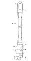
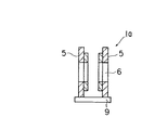
図1に示すように、テンションロッド1のロッド本体1aは、連結部材1bに連結される先端側連結部2とピン穴4を有する基端側連結部3とをその両端に有している。先端側連結部2は、図2に示すように、互いに対向する一対の側板5,5と、側板5,5同士を連結する補強板としての底板9とによって形成されている。各側板5,5の端部にはそれぞれ貫通穴6が形成されている。この場合、各側板5,5に形成された貫通穴6,6同士は互いに対向して位置している。また、貫通穴6の手元側にはバックストッパピン10が設けられており、このバックストッパピン10は、側板5,5を貫通して側板5,5間の空間を横切って延びている。
【0019】
図3に示すように、連結部材1bは、ロッド本体1aの先端側連結部2に連結される本体11と、本体11の先端側部位から下方に延びてジブ30の係合部材33に係合される係合部12と、本体11の先端に設けられジブ起伏用シリンダ60のロッド60aに連結される連結部16とから成る。本体11には、その長手方向に沿ってスライド溝15が形成されている。また、係合部12には、ジブ30の係合部材33に設けられた係合溝33a(図4および図5参照)に係合可能な係合ピン14が突設されている。
【0020】
ロッド本体1aと連結部材1bとの連結は、連結部材1bの本体11をロッド本体1aの側板5,5間に位置させた状態で、一方の側板5の貫通穴6を通じて連結ピン70(図4および図5参照)をスライド溝15に貫通させるとともに、スライド溝15を貫通した連結ピン70の端部を他方の側板5の貫通穴6に挿通してその抜けを防止することで成される。なお、この場合、連結ピン70は、回転可能に取り付けられる。
【0021】
このような連結状態では、スライド溝15に沿って連結ピン70をスライドさせることにより、連結部材1bに対するロッド本体1aの相対的な移動が可能となり、また、スライド溝15内で連結ピン70を回転させることにより、ロッド本体1aを連結部材1bに対して回動させることができる。また、この連結状態では、連結ピン70をスライド溝15の基端側終端19に位置させた状態で連結部材1bの本体11とロッド本体1aとを略一直線上に配置すると、本体11の基端面13が先端側連結部2のバックストッパピン10に当接するようになっている(図4の(a)参照)。
【0022】
ところで、図4の(a)に示すジブ張出状態では、ジブ30の各脚部30b,30bの係合部34がブームヘッド52の支持部60に係止され、ジブ30の先端側とブーム50の先端とが一対のテンションロッド1,1によって連結される。この場合、各テンションロッド1,1は、その連結部材1bの連結部16がジブ起伏用シリンダ60のロッド60aに連結され、ロッド本体1aの基端側連結部3がブームヘッド50の取付部51に連結された状態にある。なお、基端側連結部3と取付部51との連結は、基端側連結部3のピン穴4を取付部51のピン穴に一致させてこれらの穴に固定ピン40を取り付けることにより行なわれる。
【0023】
このような張出状態では、ジブ30の重量によってテンションロッド1,1が引張られるため、連結ピン70がスライド溝15の基端側終端19に位置し、連結部材1bの本体11とロッド本体1aとが略同軸に配置された直線状態となる。したがって、連結部材1bの本体11の基端面13がロッド本体1aの先端側連結部2のバックストッパピン10に当接し(これにより、スライド溝15に沿って連結ピン70をスライドさせることができず、連結部材1bに対するロッド本体1aの相対的な移動が阻止される。)、テンションロッド1,1の突張り状態(直線状態)が強固に保持される。すなわち、ジブ30を介して吊り上げた荷を急に着地させるなどしてテンションロッド1,1に作用していた引張力が急に緩んだ場合には、その煽り現象に伴なう反動力(引張力と逆方向の力)がテンションロッド1,1に作用するが、この反動力は連結部材1bの本体11の基端面13を介してバックストッパピン10によって受けられる。したがって、連結部材1bがロッド本体1aに対して回動することがなく(この回動は、反動力のかかり具合にもよるが、連結部材1bの本体11とロッド本体1aの底板9とが突き当たることによっても阻止される。)、ジブ30の後側への倒れが防止される(バックストップ機能)。
【0024】
なお、ジブ起伏用シリンダ60のロッド60aが最も収縮されジブ30が最小オフセット角に設定された図4の(a)の状態では、シリンダ60および連結部材1bの回動を阻止するために、ジブ30の係合部材33の係合溝33aに連結部材1bの係合ピン14が係合するようになっている。また、この状態からジブ起伏用シリンダ60のロッド60aを伸長させると、係合ピン14と係合溝33aとの係合が外れ、ジブ30に対するテンションロッド1,1の取り付け角が変化し、ブーム50に対するジブ30の取り付け角度が変化する。
【0025】
図4の(a)の状態(ロッド60aを最収縮させて係合ピン14と係合溝33aとを係合させた状態)から、テンションロッド1,1をジブ30の上面に沿って格納する場合には、まず、固定ピン40を抜き取ることにより、ロッド本体1aの基端側連結部3とブームヘッド50の取付部51との連結を解除して、図4の(b)に示すようにロッド本体1aを連結部材1bに対して連結ピン70を中心に回動させる。これにより、連結部材1bの基端面13とロッド本体1aのバックストッパピン10との当接状態が解除され、スライド溝15に沿う連結ピン70のスライドが可能となる。
【0026】
この状態で、今度は、ロッド本体1aを前方に押し出すことにより、連結ピン70をスライド溝15に沿ってスライドさせて、連結ピン70をスライド溝15の先端側終端に位置させる(図5の(a)参照)。これにより、ロッド本体1aの基端はジブ30の基端よりも先端側に位置され、テンションロッド1,1の基端がジブ30の基端から突出しなくなる。
【0027】
次に、ロッド本体1aを連結部材1bに対して十分に回動させた状態で、ロッド本体1aをジブ30の支持体32に連結してテンションロッド1,1をジブ30上で固定的に支持するとともに、ロッド本体1aの基端側連結部3をジブ30の固定部31に固定する。基端側連結部3と固定部31との固定は、基端側連結部3のピン穴4を固定部31の挿入穴31aに一致させて、これらの穴4,31aに先ほど抜き取った固定ピン40を取り付けることにより成される。
【0028】
図6および図7は、ブーム50がキャブ74の下側まで傾斜された状態で倒伏される自走式クレーン90において、図5の(b)の状態でテンションロッド1,1が格納されたジブ30を、ブーム50の側面に沿って格納した状態を示している。
【0029】
図示のように、ジブ30は、その基端がブーム50の先端側に向けられ且つ先端がブーム50の基端側に向けられた状態で、張り出し時におけるその上下面がブーム50の側面に沿わされ、この状態で、ブーム50の長手方向に沿って格納されている。したがって、ジブ30に格納されたテンションロッド1,1もそのロッド本体1aの基端(基端側連結部3)がブーム50の先端側に向けられるが、テンションロッド1,1は、ロッド本体1aが連結部材1bに対して相対的に移動されることによってその全長が短くなっているため、ジブ30の端部を越えて車体の前方に突出していない。
【0030】
なお、ブーム50の側面に対するジブ30の支持固定は、ブーム50の側面に取着された図示しない支持具によって着脱自在に行なわれる。このような支持具は、従来と同様の構成のもので良く、例えば、不使用時にはジブ30をブーム50の側面に沿って格納でき、ジブ30を使用する場合には、ブーム50の側面に沿って格納されているジブ30を一旦ブーム50の下面側に移し替えてから、ジブ30をブーム50下において縦方向に回動させることができるような支持具 (支持機構)や、ブーム50の側面に沿って格納されたジブ30を支点を中心に回動させてブーム50の先端下方に垂下させるとともに、垂下させたジブ30を張り出し可能な状態まで所定角度だけ捻転させてから引き上げることができるような支持具(支持機構)であることが望ましい。そのためには、このような支持機構を構成する要素をジブ30とブーム50とに設ける必要がある。
【0031】
また、本実施形態では、ジブ起伏用シリンダ60にテンションロッド1,1の連結部材1bが連結されているが、これに限らず、例えば連結部材1bがジブ30に直接に連結されるような構成としても良い。この構成によっても、バックストップ機能を確保しつつテンションロッド1,1の全長を短くするという本発明の課題を達成することができる。
【0032】
以上説明したように、本実施形態のテンションロッド1は、ロッド本体1aと連結部材1bとから構成され、ロッド本体1aが連結部材1bに対して前方にスライドすることができるとともに回動することもできるため、その全長を短くしてジブ30側に格納できる。したがって、ジブ30の端部を越えて車体の前方に突出することがない。その結果、格納時に、車体の回転半径を増大させることがなく、障害物と干渉することもない。また、ヘッドライトの照射範囲と干渉することもない。無論、このような作用効果は、図6および図7に示すタイプの自走式クレーンに限らず、ブームをキャブの上側に倒伏させた状態で走行するクレーン車においても得ることができる。また、ジブをブームの側面に沿って格納する場合のみならず、ジブをブームの下面に沿って格納する場合においても得ることができる。
【0033】
また、本実施形態のテンションロッド1は、連結ピン70をスライド溝15の基端側終端19に位置させて連結部材1bの本体11とロッド本体1aとを略同軸な直線状態に配置すれば、本体11の基端面13が機構的(自動的)に先端側連結部2のバックストッパピン10に当接するようになっている。そして、この状態は、使用時におけるジブ30の重量に伴う引張力により強固に保持される。すなわち、ピンを抜き差しするといった別個の繁雑な作業をすることなく、テンションロッド1,1の突張り状態(直線状態)が強固に保持される。したがって、ジブ30を介して吊り上げた荷を急に着地させるなどしてテンションロッド1,1に作用していた引張力が急に緩んだ場合でも、その煽り現象に伴なう反動力によって連結部材1bがロッド本体1aに対して回動することがない。つまり、繁雑な作業なくしてジブの後側への倒れを防止でき、車体に大きな振動を生じさせないで済む。
【0034】
【発明の効果】
以上説明したように、本発明のテンションロッドは、使用時にジブの後側への倒れを繁雑な作業なくして防止でき、格納時に、車体の回転半径を増大させたりヘッドライトの照射範囲と干渉することがない。
【図面の簡単な説明】
【図1】本発明の一実施形態に係るテンションロッドを構成するロッド本体の側面図である。
【図2】図1のA−A線に沿う断面図である。
【図3】本発明の一実施形態に係るテンションロッドを構成する連結部材の側面図である。
【図4】(a)は本発明の一実施形態に係るテンションロッドを用いてジブをブームの前方に張り出した状態を示す側面図、(b)はテンションロッドをブームから取り外した状態を示す側面図である。
【図5】(a)はロッド本体を連結部材に対してスライドさせてテンションロッドの全長を短くした状態を示す側面図、(b)は(a)の状態のテンションロッドをジブに固定した状態を示す側面図である。
【図6】ブームがキャブの下側まで傾斜された状態で倒伏される自走式クレーンにおいて、図5の(b)の状態でテンションロッドが格納されたジブを、ブームの側面に沿って格納した状態を示す平面図である。
【図7】図6の自走式クレーンの正面図である。
【図8】ジブとテンションロッドとをブームの側面に沿って格納する従来例を示し、 (a)は自走式クレーンの平面図、(b)は(a)の自走式クレーンの正面図である。
【符号の説明】
1…テンションロッド
1a…ロッド本体
1b…連結部材
10…バックストッパピン
15…スライド溝
70…連結ピン[0001]
TECHNICAL FIELD OF THE INVENTION
The present invention relates to a tension rod that applies a projecting force to a jib that supplements the length of a boom mounted on a crane truck or the like.
[0002]
[Prior art]
Generally, self-propelled cranes are equipped with a jib to supplement the length of the telescopic boom. This jib is used in a state where it protrudes to the tip side of the boom.At this time, the tip of the jib and the tip of the boom are connected by a pair of tension rods, and the tension force is applied to the jib by these tension rods. Is done.
[0003]
When the jib is not used, the jib is stored along the longitudinal direction of the boom. Conventionally, two methods for storing the jib are known. That is, there is a method of storing the jib along the lower surface of the boom, and a method of storing the jib along the side surface of the boom. On the other hand, the tension rod is also stored along the longitudinal direction of the boom similarly to the jib.
[0004]
FIG. 8 shows an example in which the jib and the tension rod are stored along the longitudinal direction of the boom. In the figure, 102 is a boom, 106 is a jib, and 108 is a tension rod. As shown in the drawing, the
[0005]
In the self-
[0006]
[Problems to be solved by the invention]
By the way, the tension rod generally has a longer overall length than that of the jib because it is necessary to connect the tip of the jib and the end of the boom to apply a projecting force to the jib.
[0007]
Therefore, when the tension rod is stored along the length of the boom, the end of the tension rod projects from the end of the jib. That is, referring to FIG. 8 as an example, the
[0008]
If the end of the tension rod protrudes forward of the vehicle body beyond the end of the jib as described above, the protruding end of the tension rod may interfere with an obstacle during traveling. In particular, when the turning radius of the vehicle body is increased by the protruding end portion of the tension rod, it becomes difficult to make a right or left turn in a narrow alley. In the type in which the
[0009]
In particular, in the case of the type shown in FIG. 8 in which the boom is tilted down to the lower side of the cab, the protruding end of the tension rod enters the irradiation range of the headlight, creating a shadow on the light. May be lost. Therefore, there is a concern about danger during night driving.
[0010]
The problem described above can be solved by configuring the tension rod to be bendable as shown in JP-A-7-187574, JP-A-8-1562 or JP-A-62-103594. There will be. That is, if the tension rod is divided into two parts and the divided rod parts are rotatably connected to each other, and when the storage part is retracted, the tension rod is rotated and folded at the connection part to shorten the entire length, so that the tension rod is connected to the jib. It can be prevented from protruding forward from the end.
[0011]
However, when the tension rod is configured to be rotatable about the connecting portion, one problem occurs. In other words, when lifting a load through a jib that protrudes from the end of the boom, only the pulling force normally acts on the jib and the tension rod that exerts a projecting force on the jib. If the landing is suddenly performed (this is not limited to this case), the pulling force acting on the tension rod is suddenly loosened. , The tension rod may receive a force in the direction, and the tension rod may rotate around the connecting portion. As a result, it is conceivable that the jib falls to the rear side, causing large vibrations in the vehicle body and interference between the jib and an obstacle. In particular, the possibility is high when the jib is raised up to an angle close to the standing state together with the boom. In the tension rods disclosed in JP-A-7-187574 and JP-A-8-1562, such a problem may occur because the divided rod portions are simply connected rotatably. . On the other hand, in the configuration disclosed in Japanese Utility Model Laid-Open Publication No. Sho 62-103594, the rotation at the connecting portion of the tension rod can be restricted by the pin separately attached to the tension rod. It is possible to prevent the tension rod from being inverted due to the tilting phenomenon. However, in this case, a separate pin must be inserted and removed from the tension rod, and the operation becomes very complicated.
[0012]
The present invention has been made in view of the above circumstances, and its purpose is to prevent the jib from falling down to the rear side during use without complicated work, and to increase the turning radius of the vehicle body during storage. And a tension rod that does not interfere with the irradiation range of the headlight.
[0013]
[Means for Solving the Problems]
In order to solve the above-mentioned problem, the present invention relates to a tension rod that connects a tip end side of a boom of a crane device and a tip end side of a jib that protrudes forward of the boom to apply a protruding tension to the jib. A connecting member that has a slide groove extending along the direction, and is connected to the connecting member via a connecting member that is attached to a tip side of the jib and a connecting pin that is slidable along the sliding groove of the connecting member. A rod main body to be attached, wherein the rod main body has a back stopper pin that can abut on a connection side end face of the connection member in a state where the connection pin is located at the end of the slide groove. I do.
[0014]
BEST MODE FOR CARRYING OUT THE INVENTION
Hereinafter, embodiments of the present invention will be described with reference to the drawings.
FIG. 4A illustrates a state in which the
[0015]
As shown, the tension rod 1 includes an elongated rod body 1a and a connecting member 1b connected to the rod body 1a. The
[0016]
A
[0017]
An engaging member 33 is provided on the upper surface of the distal end side of each of the
[0018]
As shown in FIG. 1, the rod body 1a of the tension rod 1 has a distal-
[0019]
As shown in FIG. 3, the connecting member 1 b is engaged with the main body 11 connected to the distal
[0020]
The connection between the rod body 1a and the connecting member 1b is performed by connecting the connecting pin 70 (see FIG. And FIG. 5) are passed through the
[0021]
In such a connection state, by sliding the
[0022]
By the way, in the jib overhang state shown in FIG. 4A, the engaging
[0023]
In such an extended state, the tension rods 1 and 1 are pulled by the weight of the
[0024]
In the state of FIG. 4A in which the rod 60a of the
[0025]
The tension rods 1 and 1 are stored along the upper surface of the
[0026]
In this state, the connecting
[0027]
Next, in a state where the rod body 1a is sufficiently rotated with respect to the connecting member 1b, the rod body 1a is connected to the
[0028]
FIGS. 6 and 7 show a jib in which tension rods 1, 1 are stored in a state shown in FIG. 5B in a self-propelled
[0029]
As shown, the
[0030]
The
[0031]
In the present embodiment, the connecting member 1b of the tension rods 1, 1 is connected to the
[0032]
As described above, the tension rod 1 according to the present embodiment includes the rod body 1a and the connecting member 1b, and the rod body 1a can slide forward with respect to the connecting member 1b and can also rotate. Therefore, the overall length can be shortened and stored in the
[0033]
Further, in the tension rod 1 of the present embodiment, if the connecting
[0034]
【The invention's effect】
As described above, the tension rod of the present invention can prevent the jib from falling to the rear side during use without complicated work, and when stored, increase the turning radius of the vehicle body or interfere with the irradiation range of the headlight. Nothing.
[Brief description of the drawings]
FIG. 1 is a side view of a rod main body constituting a tension rod according to an embodiment of the present invention.
FIG. 2 is a sectional view taken along line AA of FIG.
FIG. 3 is a side view of a connecting member constituting a tension rod according to one embodiment of the present invention.
FIG. 4A is a side view showing a state in which a jib is extended to the front of a boom using a tension rod according to an embodiment of the present invention, and FIG. 4B is a side view showing a state in which the tension rod is removed from the boom. FIG.
5A is a side view showing a state in which the entire length of the tension rod is shortened by sliding the rod body with respect to the connecting member, and FIG. 5B is a state in which the tension rod in the state of FIG. FIG.
FIG. 6 is a perspective view of a self-propelled crane in which the boom is tilted down to the lower side of the cab, and the jib in which the tension rod is stored in the state of FIG. 5B is stored along the side of the boom. It is a top view showing the state where it did.
FIG. 7 is a front view of the self-propelled crane of FIG.
8A and 8B show a conventional example in which a jib and a tension rod are stored along a side surface of a boom, wherein FIG. 8A is a plan view of a self-propelled crane, and FIG. 8B is a front view of the self-propelled crane of FIG. It is.
[Explanation of symbols]
DESCRIPTION OF SYMBOLS 1 ... Tension rod 1a ... Rod main body 1b ...
Claims (1)
その長手方向に沿って延びるスライド溝を有し、ジブの先端側に取り付けられる連結部材と、
前記連結部材のスライド溝に沿ってスライド可能な連結ピンを介して前記連結部材に連結され、ブームの先端に取り付けられるロッド本体と、
を具備し、
前記ロッド本体は、前記連結ピンがスライド溝の終端に位置した状態で連結部材の連結側端面と当接可能なバックストッパピンを有していることを特徴とするテンションロッド。In a tension rod that connects a tip end side of a boom of a crane device and a tip end side of a jib protruding forward of the boom to apply a projecting tension to the jib,
A connecting member having a slide groove extending along the longitudinal direction thereof and attached to a tip side of the jib;
A rod body connected to the connection member via a connection pin slidable along a slide groove of the connection member and attached to a tip of a boom;
With
A tension rod, wherein the rod body has a back stopper pin that can abut on a connection-side end surface of a connection member in a state where the connection pin is located at the end of a slide groove.
Priority Applications (1)
| Application Number | Priority Date | Filing Date | Title |
|---|---|---|---|
| JP04917097A JP3578583B2 (en) | 1997-03-04 | 1997-03-04 | Tension rod |
Applications Claiming Priority (1)
| Application Number | Priority Date | Filing Date | Title |
|---|---|---|---|
| JP04917097A JP3578583B2 (en) | 1997-03-04 | 1997-03-04 | Tension rod |
Publications (2)
| Publication Number | Publication Date |
|---|---|
| JPH10245190A JPH10245190A (en) | 1998-09-14 |
| JP3578583B2 true JP3578583B2 (en) | 2004-10-20 |
Family
ID=12823606
Family Applications (1)
| Application Number | Title | Priority Date | Filing Date |
|---|---|---|---|
| JP04917097A Expired - Fee Related JP3578583B2 (en) | 1997-03-04 | 1997-03-04 | Tension rod |
Country Status (1)
| Country | Link |
|---|---|
| JP (1) | JP3578583B2 (en) |
Families Citing this family (2)
| Publication number | Priority date | Publication date | Assignee | Title |
|---|---|---|---|---|
| JP4964520B2 (en) * | 2006-07-07 | 2012-07-04 | 株式会社加藤製作所 | Telescopic cylinder storage device for jib undulation operation of crane truck |
| JP6536145B2 (en) * | 2015-04-16 | 2019-07-03 | 株式会社タダノ | Tension rod storage structure |
-
1997
- 1997-03-04 JP JP04917097A patent/JP3578583B2/en not_active Expired - Fee Related
Also Published As
| Publication number | Publication date |
|---|---|
| JPH10245190A (en) | 1998-09-14 |
Similar Documents
| Publication | Publication Date | Title |
|---|---|---|
| US3698569A (en) | Mobile crane with jib extension | |
| JP4857880B2 (en) | Mobile crane boom mounting method and boom mounting tool | |
| JP3578583B2 (en) | Tension rod | |
| JP3566418B2 (en) | Mobile crane with luffing jib | |
| JPS612693A (en) | Jib housing device for car type crane | |
| JPH07309589A (en) | Counterweight device for crane car | |
| JP3442890B2 (en) | Self-propelled mobile crane jib | |
| JP2000257116A (en) | Construction machinery | |
| JPS6011024Y2 (en) | Auxiliary pulley device for telescopic boom type crane with auxiliary jib | |
| JP4191955B2 (en) | Jib storage mechanism of crane equipment | |
| JPH0412075Y2 (en) | ||
| JPH0318471Y2 (en) | ||
| JP3652437B2 (en) | Self-propelled crane boom head retracting mechanism | |
| JPH10218565A (en) | Tension rod | |
| JPH0930778A (en) | Jib tensioner in jib crane truck | |
| JP2019199310A (en) | Specification changing method of crane and specification-changeable crane | |
| JP3537233B2 (en) | Apparatus and method for exchanging wire rope during jib overhang and storage | |
| JP2726006B2 (en) | Wheel crane jib containment device | |
| JPH0328069Y2 (en) | ||
| JP3412268B2 (en) | Wheeled crane jib | |
| JPH0350148Y2 (en) | ||
| JPH07472Y2 (en) | Luffing jib device | |
| JP3658116B2 (en) | Jib overhang storage mechanism of self-propelled crane | |
| JPH0754230Y2 (en) | Tension device mounting structure for boom with jib | |
| JPH0439296A (en) | Crane jib overhanging and storing and its device |
Legal Events
| Date | Code | Title | Description |
|---|---|---|---|
| A977 | Report on retrieval |
Free format text: JAPANESE INTERMEDIATE CODE: A971007 Effective date: 20040607 |
|
| TRDD | Decision of grant or rejection written | ||
| A01 | Written decision to grant a patent or to grant a registration (utility model) |
Free format text: JAPANESE INTERMEDIATE CODE: A01 Effective date: 20040615 |
|
| A61 | First payment of annual fees (during grant procedure) |
Free format text: JAPANESE INTERMEDIATE CODE: A61 Effective date: 20040713 |
|
| R150 | Certificate of patent or registration of utility model |
Free format text: JAPANESE INTERMEDIATE CODE: R150 |
|
| LAPS | Cancellation because of no payment of annual fees |