【0001】
【考案の属する技術分野】
本考案は、放熱モジュールに係り、特に、エアの流動方向を案内するための案内部材を有することにより、温度を快速に下げることができる放熱モジュールに関する。
【0002】
【従来の技術】
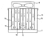
図5に示すのは、従来の放熱モジュールであり、台座7を有し、前記台座7には多数の並列した放熱フィン71が設けられており、なお、エアを流通するために各放熱フィン71の間は別々にギャップ72を有する。上記構成を有する放熱モジュールを放熱必要な部材(例えば、パソコンのCPUまたは熱伝導リード)に組み付け、また、放熱ファン8を前記放熱モジュールに組み付け、前記放熱ファン7によりエアを各放熱フィン71のギャップ72のなかで流動させ、台座7まで伝導されてきた熱を放熱することができる。
【0003】
【考案が解決しようとする課題】
これは、次のような欠点があった。
上記放熱モジュールの台座7は平面であるので、放熱ファン8が運転している際に、流動されたエアが台座8に着くと、反発の圧力が発生するため、エアが各放熱フィン71の間のギャップ72のなかに環流を形成し、放熱効率が低下し、放熱フィン71まで伝導されてきた熱が有効に放熱できない。
【0004】
【課題を解決するための手段】
上記欠点を解決するためになされた本考案の請求項1は、放熱フィン組を設けた台座を有し、前記放熱フィン組には多数の放熱フィンが並列しており、前記各放熱フィンの間は同様なギャップを有し、なお、前記放熱フィン組のなかには案内部材が嵌められており、前記案内部材の両側は別々に前記各放熱フィンのギャップに挿入された多数の案内片を有し、前記各案内片は前記各ギャップの頂端から下へ傾斜して底端まで伸び、前記ギャップのなかのエアの流動方向を案内することを特徴とする放熱モジュールであることを要旨としている。
【0005】
本考案の請求項2では、前記放熱フィン組の頂端の中央部は案内部材を嵌めるための嵌め溝を有することを特徴とする請求項1に記載の放熱モジュールであることを要旨としている。
【0006】
本考案の請求項3では、前記案内部材の各案内片はそれぞれやや窪んだ円弧面を有することを特徴とする請求項1に記載の放熱モジュールであることを要旨としている。
【0007】
本考案の請求項4では、前記台座は前記放熱フィン組を収容するための上へ開口した収容窪みを有し、前記放熱フィン組は金属片から一体に曲がって多数の中空の放熱フィンを連続で形成し、前記各放熱フィンの底部はそれぞれ連接面により連接され、なお、前記放熱フィン組は更に前記台座の収容窪みのなかに嵌められるための嵌合ブロックを有し、前記嵌合ブロックは別々に前記各放熱フィンを底部の連接面まで嵌め込むための多数の嵌め溝を有することを特徴とする請求項1に記載の放熱モジュールであることを要旨としている。
【0008】
本考案の請求項5では、前記放熱フィン組は多数の中空でない放熱フィンを有し、前記各放熱フィンの底部はそれぞれ底面により連接されていることを特徴とする請求項1に記載の放熱モジュールであることを要旨としている。
【0009】
【考案の実施の形態】
図1から図3を参照する。本考案の一実施例による放熱モジュールは、放熱フィン組を設けた台座1を有し、前記台座1は前記放熱フィン組2を収容するための上へ開口した収容窪み11を有し、本実施例では、前記放熱フィン組2は金属片から一体に曲げられて多数の中空の放熱フィン21を連続で形成し、前記各放熱フィン21の底部はそれぞれ連接面23により連接されている。
【0010】
前記放熱フィン組2は更に前記台座1の収容窪み11のなかに嵌められるための嵌合ブロック3を有し、前記嵌合ブロック3は別々に前記各放熱フィン21を底部の連接面23まで嵌め込むための多数の嵌め溝31を有し、なお、前記放熱フィン組2を台座1に嵌めるように前記各放熱フィン21の底部は前記台座1の収容窪み11のなかに嵌められている。
【0011】
前記放熱フィン組2の頂端の中央部は案内部材4を嵌めるための嵌め溝24を有し、前記案内部材4の両側は別々に前記各放熱フィン21のギャップ22に挿入された多数の案内片41を有し、本実施例では、前記各案内片41は前記各ギャップ22の頂端から下へ傾斜して底端まで伸び、前記ギャップ22のなかのエアの流動方向を案内する。
【0012】
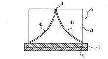
これにより、図4に示すように、上記構成の放熱モジュールを放熱必要な部材(例えば、パソコンのCPUまたは熱伝導リード)に組み付けることができる。本実施例では、前記放熱モジュールの台座1はパソコンのCPU5に取り付けられ、且つ、前記放熱モジュールの放熱フィン組2の頂端には放熱ファン6が設けられており、前記放熱ファン6の回転によりエアを前記放熱フィン組2の各放熱フィン21のギャップ22のなかで流動させ、各放熱フィン21まで伝導されてきた熱を放熱する。
【0013】
該案内部材4の案内片41は各放熱フィン21のギャップ22の頂端の中央部から両側へ傾斜して下向きに伸びるため、前記放熱ファン4の回転によりエアは前記流れ案内面41に沿って外側へ流出し、エアは前記ギャップ22のなかで環流を形成せず、ひいては、各放熱フィン21まで伝導されてきた熱を有効に放熱して温度を低減し、より優れた放熱効果を得ることができる。
【0014】
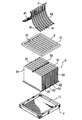
図5に示すのは、本考案の他の実施例であり、前記放熱フィン組2は多数の中空でない放熱フィン21を有し、前記各放熱フィン21の底部はそれぞれ底面25により連接され、且つ、前記案内部材4が嵌められているために、前記放熱フィン組2の頂端の中央部は該嵌め溝24を有する。前記案内部材4により各放熱フィン21まで伝導されてきた熱を快速に放熱することができる。
【0015】
この考案は次のような効果がある。
該案内部材の案内片は各放熱フィンのギャップの頂端の中央部から両側へ傾斜して下向きに伸びるため、エアが前記流れ案内面に沿って外側へ流出し、エアは前記ギャップのなかで環流を形成せず、ひいては、各放熱フィンまで伝導されてきた熱を有効に放熱して温度を低減し、より優れた放熱効果を得ることができる。
【図面の簡単な説明】
【図1】本考案の一実施例による放熱モジュールを示す斜視図である。
【図2】本考案の一実施例による放熱モジュールを示す分解斜視図である。
【図3】本考案の一実施例による放熱モジュールを示す断面図である。
【図4】本考案の一実施例による放熱モジュールの案内片によりエアを案内する状態を示す模式図である。
【図5】本考案の他の実施例による放熱モジュールを示す分解斜視図である。
【図6】従来の放熱モジュールを示す模式図である。
【符号の説明】
1 台座
2 放熱フィン組
3 嵌合ブロック
4 案内部材
6 放熱ファン
11 収容窪み
21 放熱フィン
22 ギャップ
23 連接面
24 嵌め溝
25 底面
31 嵌め溝
41 案内片[0001]
[Technical field to which the invention belongs]
The present invention relates to a heat radiating module, and more particularly to a heat radiating module that has a guide member for guiding a flow direction of air so that the temperature can be rapidly reduced.
[0002]
[Prior art]
FIG. 5 shows a conventional heat dissipating module having a pedestal 7 on which a number of parallel radiating fins 71 are provided. Have a gap 72 separately. The radiating module having the above configuration is mounted on a member (for example, a CPU of a personal computer or a heat conducting lead) that requires radiating, the radiating fan 8 is mounted on the radiating module, and the radiating fan 7 disperses air into the gap of each radiating fin 71. The heat flowing through the base 72 can be radiated.
[0003]
[Problems to be solved by the invention]
This has the following disadvantages.
Since the pedestal 7 of the heat radiating module is flat, when the radiating fan 8 is operated, if the flowed air reaches the pedestal 8, a repulsive pressure is generated. A reflux is formed in the gap 72, and the heat radiation efficiency is reduced, so that the heat conducted to the heat radiation fins 71 cannot be effectively dissipated.
[0004]
[Means for Solving the Problems]
Claim 1 of the present invention made in order to solve the above-mentioned drawback has a pedestal provided with a radiating fin set, and a large number of radiating fins are arranged in parallel in the radiating fin set, and between each of the radiating fins. Has a similar gap, a guide member is fitted in the radiation fin set, and both sides of the guide member have a number of guide pieces separately inserted into the gaps of the radiation fins, The gist of the invention is that each of the guide pieces is a heat dissipating module characterized in that it is inclined downward from the top end of each of the gaps and extends to the bottom end to guide the flow direction of air in the gaps.
[0005]
According to a second aspect of the present invention, there is provided a heat radiation module according to the first aspect, wherein a central portion of a top end of the heat radiation fin set has a fitting groove for fitting a guide member.
[0006]
According to a third aspect of the present invention, there is provided a heat radiation module according to the first aspect, wherein each guide piece of the guide member has a slightly concave arc surface.
[0007]
According to claim 4 of the present invention, the pedestal has an accommodation recess opened upward for accommodating the radiating fin set, and the radiating fin set is bent integrally from a metal piece to connect a large number of hollow radiating fins. The bottom of each of the radiating fins is connected by a connecting surface, and the radiating fin set further includes a fitting block for fitting into the accommodation recess of the pedestal. The heat dissipation module according to claim 1, wherein the heat dissipation fin has a large number of fitting grooves for separately fitting each of the heat dissipation fins to the connecting surface of the bottom.
[0008]
The radiating module according to claim 1, wherein the radiating fin set includes a plurality of solid radiating fins, and a bottom portion of each of the radiating fins is connected by a bottom surface. The gist is that
[0009]
[Embodiment of the invention]
Please refer to FIG. 1 to FIG. The heat dissipating module according to one embodiment of the present invention has a pedestal 1 provided with a radiating fin set, and the pedestal 1 has a receiving recess 11 opened upward for receiving the radiating fin set 2. In the example, the heat dissipating fin set 2 is integrally bent from a metal piece to form a large number of hollow heat dissipating fins 21 continuously, and the bottoms of the heat dissipating fins 21 are connected by connecting surfaces 23 respectively.
[0010]
The radiating fin set 2 further has a fitting block 3 for fitting into the accommodation recess 11 of the pedestal 1, and the fitting block 3 separately fits each of the radiating fins 21 to the connecting surface 23 at the bottom. There are a number of fitting grooves 31 for fitting the radiating fins 2, and the bottom of each of the radiating fins 21 is fitted into the accommodation recess 11 of the pedestal 1 so that the radiating fin set 2 is fitted to the pedestal 1.
[0011]
The center of the top end of the radiating fin set 2 has a fitting groove 24 for fitting the guide member 4, and both sides of the guide member 4 are provided with a number of guide pieces separately inserted into the gaps 22 of the radiating fins 21. In the present embodiment, each of the guide pieces 41 is inclined downward from the top end of each of the gaps 22 and extends to the bottom end, and guides the flow direction of air in the gaps 22.
[0012]
As a result, as shown in FIG. 4, the heat dissipation module having the above configuration can be assembled to a member requiring heat dissipation (for example, a CPU of a personal computer or a heat conduction lead). In this embodiment, the pedestal 1 of the heat dissipation module is attached to the CPU 5 of the personal computer, and a heat dissipation fan 6 is provided at the top end of the heat dissipation fin set 2 of the heat dissipation module. Is caused to flow in the gaps 22 of the heat radiation fins 21 of the heat radiation fin set 2, and the heat conducted to each heat radiation fin 21 is radiated.
[0013]
Since the guide piece 41 of the guide member 4 is inclined downward to both sides from the center of the top end of the gap 22 of each radiation fin 21 and extends downward, the rotation of the radiation fan 4 causes air to flow outward along the flow guide surface 41. The air does not form a circulating flow in the gap 22, thereby effectively radiating the heat conducted to each of the radiating fins 21 to reduce the temperature, thereby obtaining a better heat radiating effect. it can.
[0014]
FIG. 5 shows another embodiment of the present invention, in which the radiating fin set 2 has a plurality of solid radiating fins 21, the bottoms of the radiating fins 21 are respectively connected by bottom surfaces 25, and Since the guide member 4 is fitted, the center of the top end of the radiating fin set 2 has the fitting groove 24. The heat conducted to the radiation fins 21 by the guide member 4 can be quickly radiated.
[0015]
This invention has the following effects.
Since the guide pieces of the guide members are inclined downward from the center of the top end of the gap of each radiating fin and extend downward, air flows outward along the flow guide surface, and the air flows back inside the gaps. Therefore, the heat conducted to each of the heat radiation fins is effectively radiated to reduce the temperature, and a more excellent heat radiation effect can be obtained.
[Brief description of the drawings]
FIG. 1 is a perspective view showing a heat dissipation module according to an embodiment of the present invention.
FIG. 2 is an exploded perspective view showing the heat radiation module according to the embodiment of the present invention;
FIG. 3 is a cross-sectional view illustrating a heat dissipation module according to an embodiment of the present invention;
FIG. 4 is a schematic view showing a state in which air is guided by a guide piece of the heat radiation module according to the embodiment of the present invention;
FIG. 5 is an exploded perspective view showing a heat dissipation module according to another embodiment of the present invention.
FIG. 6 is a schematic view showing a conventional heat dissipation module.
[Explanation of symbols]
REFERENCE SIGNS 1 pedestal 2 radiating fin set 3 fitting block 4 guide member 6 radiating fan 11 receiving recess 21 radiating fin 22 gap 23 connecting surface 24 fitting groove 25 bottom surface 31 fitting groove 41 guide piece