JP2022014176A - Laser device - Google Patents

Laser device Download PDF

Info

Publication number
JP2022014176A
JP2022014176A JP2020116378A JP2020116378A JP2022014176A JP 2022014176 A JP2022014176 A JP 2022014176A JP 2020116378 A JP2020116378 A JP 2020116378A JP 2020116378 A JP2020116378 A JP 2020116378A JP 2022014176 A JP2022014176 A JP 2022014176A
Authority
JP
Japan
Prior art keywords
chamber
supported
gantry
respect
resonator
Prior art date
Legal status (The legal status is an assumption and is not a legal conclusion. Google has not performed a legal analysis and makes no representation as to the accuracy of the status listed.)
Pending
Application number
JP2020116378A
Other languages
Japanese (ja)
Inventor
譲一 河村
Joichi Kawamura
研太 田中
Kenta Tanaka
Current Assignee (The listed assignees may be inaccurate. Google has not performed a legal analysis and makes no representation or warranty as to the accuracy of the list.)
Sumitomo Heavy Industries Ltd
Original Assignee
Sumitomo Heavy Industries Ltd
Priority date (The priority date is an assumption and is not a legal conclusion. Google has not performed a legal analysis and makes no representation as to the accuracy of the date listed.)
Filing date
Publication date
Application filed by Sumitomo Heavy Industries Ltd filed Critical Sumitomo Heavy Industries Ltd
Priority to JP2020116378A priority Critical patent/JP2022014176A/en
Priority to KR1020210078436A priority patent/KR20220005392A/en
Priority to TW110122576A priority patent/TWI834977B/en
Priority to CN202110706451.7A priority patent/CN113904204A/en
Publication of JP2022014176A publication Critical patent/JP2022014176A/en
Pending legal-status Critical Current

Links

Images

Classifications

    • HELECTRICITY
    • H01ELECTRIC ELEMENTS
    • H01SDEVICES USING THE PROCESS OF LIGHT AMPLIFICATION BY STIMULATED EMISSION OF RADIATION [LASER] TO AMPLIFY OR GENERATE LIGHT; DEVICES USING STIMULATED EMISSION OF ELECTROMAGNETIC RADIATION IN WAVE RANGES OTHER THAN OPTICAL
    • H01S3/00Lasers, i.e. devices using stimulated emission of electromagnetic radiation in the infrared, visible or ultraviolet wave range
    • H01S3/02Constructional details
    • H01S3/025Constructional details of solid state lasers, e.g. housings or mountings
    • H01S3/027Constructional details of solid state lasers, e.g. housings or mountings comprising a special atmosphere inside the housing
    • HELECTRICITY
    • H01ELECTRIC ELEMENTS
    • H01SDEVICES USING THE PROCESS OF LIGHT AMPLIFICATION BY STIMULATED EMISSION OF RADIATION [LASER] TO AMPLIFY OR GENERATE LIGHT; DEVICES USING STIMULATED EMISSION OF ELECTROMAGNETIC RADIATION IN WAVE RANGES OTHER THAN OPTICAL
    • H01S3/00Lasers, i.e. devices using stimulated emission of electromagnetic radiation in the infrared, visible or ultraviolet wave range
    • H01S3/02Constructional details
    • H01S3/03Constructional details of gas laser discharge tubes
    • HELECTRICITY
    • H01ELECTRIC ELEMENTS
    • H01SDEVICES USING THE PROCESS OF LIGHT AMPLIFICATION BY STIMULATED EMISSION OF RADIATION [LASER] TO AMPLIFY OR GENERATE LIGHT; DEVICES USING STIMULATED EMISSION OF ELECTROMAGNETIC RADIATION IN WAVE RANGES OTHER THAN OPTICAL
    • H01S3/00Lasers, i.e. devices using stimulated emission of electromagnetic radiation in the infrared, visible or ultraviolet wave range
    • H01S3/05Construction or shape of optical resonators; Accommodation of active medium therein; Shape of active medium
    • H01S3/08Construction or shape of optical resonators or components thereof
    • H01S3/081Construction or shape of optical resonators or components thereof comprising three or more reflectors

Abstract

To provide a laser device that is less prone to misalignment of a laser beam path even when a chamber is thermally deformed.SOLUTION: A chamber houses a laser medium gas and an optical resonator. A stand supports the chamber. At one point, a horizontal position of the chamber relative to the stand is constrained. The chamber is supported so that it can be moved horizontally with respect to the stand except where the horizontal position of the chamber with respect to the stand is constrained.SELECTED DRAWING: Figure 4

Description

本発明は、レーザ装置に関する。 The present invention relates to a laser device.

ガスレーザ発振器のチェンバが架台に支持される。この構造において、通常はチェンバを4か所で架台に固定する。三軸直交型のレーザ発振器では、放電電極での放電を安定させるために、チェンバ内のレーザ媒質ガスを高速で循環させる。一対の放電電極の間の放電領域にレーザ媒質ガスが流入し、放電によって高温になったレーザ媒質ガスが放電領域からチェンバ内の他の領域に排出される。放電領域から排出されたレーザ媒質ガスは、熱交換器によって冷却され、放電領域に再流入する。放電を経て高温になったレーザ媒質ガスにより、チェンバが熱膨張する。チェンバが熱膨張すると、チェンバの変形に応じて架台も変形する。 The chamber of the gas laser oscillator is supported by the gantry. In this structure, the chamber is usually fixed to the gantry at four locations. In the three-axis orthogonal type laser oscillator, the laser medium gas in the chamber is circulated at high speed in order to stabilize the discharge at the discharge electrode. The laser medium gas flows into the discharge region between the pair of discharge electrodes, and the laser medium gas heated to a high temperature by the discharge is discharged from the discharge region to another region in the chamber. The laser medium gas discharged from the discharge region is cooled by the heat exchanger and re-flows into the discharge region. The chamber is thermally expanded by the laser medium gas that has become hot after being discharged. When the chamber thermally expands, the gantry also deforms according to the deformation of the chamber.

下記の特許文献1に、光共振器のミラーをチェンバの外に配置したガスレーザ発振器が開示されている。チェンバと光共振器ミラーとは、別々の架台に固定されている。このため、チェンバやその架台が熱変形しても、光共振器はその熱変形の影響を受けにくい。 Patent Document 1 below discloses a gas laser oscillator in which a mirror of an optical resonator is arranged outside the chamber. The chamber and the optical resonator mirror are fixed to separate mounts. Therefore, even if the chamber and its gantry are thermally deformed, the optical resonator is not easily affected by the thermal deformation.

特開平2-105478号公報Japanese Unexamined Patent Publication No. 2-105478

チェンバの内部に光共振器のミラーが配置されている構成では、チェンバの熱変形によって架台が変形すると、チェンバの姿勢が変化し、チェンバ内の光共振器のミラーの姿勢や位置も変化する。その結果、光共振器の光軸が初期の位置からずれてしまう。光共振器の光軸がずれると、レーザ発振器の後段に配置されているビーム整形光学系等へのレーザビームの入射位置にもずれが生じる。ビーム整形光学系への入射位置がずれると、加工面におけるビームプロファイルが崩れてしまい、加工品質が低下してしまう。 In the configuration in which the mirror of the optical resonator is arranged inside the chamber, when the gantry is deformed due to the thermal deformation of the chamber, the posture of the chamber changes, and the posture and position of the mirror of the optical resonator in the chamber also change. As a result, the optical axis of the optical resonator deviates from the initial position. When the optical axis of the optical resonator shifts, the position of the laser beam incident on the beam shaping optical system or the like arranged after the laser oscillator also shifts. If the position of incidence on the beam shaping optical system shifts, the beam profile on the machined surface collapses and the machining quality deteriorates.

本発明の目的は、チェンバが熱変形しても、レ―ザビームの経路にずれが生じにくいレーザ装置を提供することである。 An object of the present invention is to provide a laser apparatus in which the path of a laser beam is less likely to shift even if the chamber is thermally deformed.

本発明の一観点によると、
レーザ媒質ガス及び光共振器を収容するチェンバと、
前記チェンバを支持する架台と
を有し、
前記チェンバは、1箇所で、前記架台に対する前記チェンバの水平方向の位置が拘束されており、
前記架台に対する前記チェンバの水平方向の位置が拘束されている箇所以外では、前記チェンバが前記架台に対して水平方向に移動可能に支持されているレーザ装置が提供される。
According to one aspect of the invention
A chamber that houses the laser medium gas and the optical resonator,
It has a stand to support the chamber and
The chamber is constrained in one place by the horizontal position of the chamber with respect to the gantry.
A laser device is provided in which the chamber is movably supported in the horizontal direction with respect to the gantry, except where the horizontal position of the chamber with respect to the gantry is constrained.

チェンバが熱変形しても、架台はその変形の影響を受けにくい。これにより、チェンバの姿勢の変動が軽減され、レーザビームの経路のずれも生じにくくなる。 Even if the chamber is thermally deformed, the gantry is not easily affected by the deformation. As a result, the fluctuation of the posture of the chamber is reduced, and the deviation of the path of the laser beam is less likely to occur.

図1は、本実施例によるレーザ装置、及びレーザ装置から出力されたレーザビームで加工を行う加工装置の概略図である。FIG. 1 is a schematic view of a laser apparatus according to the present embodiment and a processing apparatus that performs processing with a laser beam output from the laser apparatus. 図2は、実施例によるレーザ装置の側面図であり、レーザ発振器については断面を示した図である。FIG. 2 is a side view of the laser apparatus according to the embodiment, and is a view showing a cross section of the laser oscillator. 図3は、実施例によるレーザ装置の光軸に垂直な断面図である。FIG. 3 is a cross-sectional view perpendicular to the optical axis of the laser device according to the embodiment. 図4は、実施例によるレーザ装置のチェンバ及び架台の平面図である。FIG. 4 is a plan view of the chamber and the gantry of the laser device according to the embodiment. 図5A及び図5Bは、それぞれ図4の一点鎖線5A-5A及び一点鎖線5B-5Bにおける断面図である。5A and 5B are cross-sectional views of the alternate long and short dash line 5A-5A and the alternate long and short dash line 5B-5B of FIG. 4, respectively. 図6Aは、実施例によるレーザ装置の共振器ベースの平面図であり、図6B及び図6Cは、それぞれ図6Aの一点鎖線6B-6B及び一点鎖線6C-6Cにおける断面図である。6A is a plan view of the resonator base of the laser apparatus according to the embodiment, and FIGS. 6B and 6C are cross-sectional views taken along the alternate long and short dash line 6B-6B and the alternate long and short dash line 6C-6C, respectively. 図7A及び図7Bは、それぞれ比較例によるレーザ装置の概略平面図及び概略断面図である。7A and 7B are a schematic plan view and a schematic cross-sectional view of a laser apparatus according to a comparative example, respectively.

図1~図7Bを参照して、実施例によるレーザ装置について説明する。
図1は、実施例によるレーザ装置10、及びレーザ装置10から出力されたレーザビームで加工を行う加工装置80の概略図である。共通ベース100に、レーザ装置10及び加工装置80が固定されている。共通ベース100は、例えば床である。
A laser apparatus according to an embodiment will be described with reference to FIGS. 1 to 7B.
FIG. 1 is a schematic view of a laser device 10 according to an embodiment and a processing device 80 that performs processing with a laser beam output from the laser device 10. The laser device 10 and the processing device 80 are fixed to the common base 100. The common base 100 is, for example, a floor.

レーザ装置10は、共通ベース100に固定された架台11と、架台11に支持されたレーザ発振器12とを含む。加工装置80は、ビーム整形光学系81及びステージ82を含む。ステージ82の上に加工対象物90が保持される。ビーム整形光学系81及びステージ82は、共通ベース100に固定されている。レーザ発振器12から出力されたレーザビームが、ビーム整形光学系81によってビームプロファイルを整形され、加工対象物90に入射する。 The laser device 10 includes a gantry 11 fixed to the common base 100 and a laser oscillator 12 supported by the gantry 11. The processing apparatus 80 includes a beam shaping optical system 81 and a stage 82. The object to be machined 90 is held on the stage 82. The beam shaping optical system 81 and the stage 82 are fixed to the common base 100. The laser beam output from the laser oscillator 12 has its beam profile shaped by the beam shaping optical system 81, and is incident on the object to be machined 90.

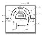
図2は、レーザ装置10の側面図であり、レーザ発振器12については断面を示した図である。レーザ発振器12は、レーザ媒質ガス及び光共振器20等を収容するチェンバ15を含む。チェンバ15が、4箇所で架台11に支持されている。すなわち、架台11は、4箇所でチェンバ15からの荷重を受け止める。図2では、チェンバ15が架台11に支持されている箇所を三角形30で示している。図2は、三角形30によってチェンバ15が架台11に支持されている箇所を模式的に表しているのみであり、三角形30は架台11がチェンバ15を支持する支持構造の形状を表しているわけではない。架台11は、4個の架台脚13によって共通ベース100の上に支持される。図2は、架台脚13を模式的に三角形で表しており、架台脚13の形状を表しているわけではない。なお、後に説明する放電電極支持部材23及び光共振器支持部材27も、図2では模式的に表されている。 FIG. 2 is a side view of the laser apparatus 10, and is a cross-sectional view of the laser oscillator 12. The laser oscillator 12 includes a chamber 15 that houses a laser medium gas, an optical resonator 20, and the like. The chamber 15 is supported by the gantry 11 at four points. That is, the gantry 11 receives the load from the chamber 15 at four points. In FIG. 2, the portion where the chamber 15 is supported by the gantry 11 is indicated by a triangle 30. FIG. 2 only schematically shows the portion where the chamber 15 is supported by the gantry 11 by the triangle 30, and the triangle 30 does not represent the shape of the support structure in which the gantry 11 supports the chamber 15. do not have. The gantry 11 is supported on the common base 100 by four gantry legs 13. FIG. 2 schematically represents the gantry leg 13 as a triangle, and does not represent the shape of the gantry leg 13. The discharge electrode support member 23 and the optical resonator support member 27, which will be described later, are also schematically shown in FIG.

次に、レーザ発振器12の構成について説明する。チェンバ15にレーザ媒質ガスが収容される。チェンバ15の内部空間が、相対的に上側に位置する光学室16と、相対的に下側に位置するブロワ室17とに区分されている。光学室16とブロワ室17とは、上下仕切り板18で仕切られている。なお、上下仕切り板18には、レーザガスを光学室16とブロワ室17との間で流通させる開口が設けられている。ブロワ室17の側壁から光学室16の底板19が光共振器20の光軸20Aの方向に張り出しており、光学室16の光軸方向の長さが、ブロワ室17の光軸方向の長さより長くなっている。チェンバ15は、底板19により、または底板19に固定された部材を介して架台11に支持される。 Next, the configuration of the laser oscillator 12 will be described. The laser medium gas is housed in the chamber 15. The internal space of the chamber 15 is divided into an optical chamber 16 located relatively above and a blower chamber 17 located relatively below. The optical chamber 16 and the blower chamber 17 are partitioned by an upper and lower partition plate 18. The upper and lower partition plates 18 are provided with openings for allowing laser gas to flow between the optical chamber 16 and the blower chamber 17. The bottom plate 19 of the optical chamber 16 projects from the side wall of the blower chamber 17 in the direction of the optical axis 20A of the optical resonator 20, and the length of the optical chamber 16 in the optical axis direction is larger than the length of the optical chamber 17 in the optical axis direction. It's getting longer. The chamber 15 is supported by the gantry 11 by the bottom plate 19 or via a member fixed to the bottom plate 19.

光学室16内に、一対の放電電極21及び一対の共振器ミラー25が配置されている。一対の放電電極21は、それぞれ放電電極支持部材22、23を介して底板19に支持されている。一対の放電電極21は、上下方向に間隔を隔てて配置され、両者の間に放電領域24が画定される。放電電極21は放電領域24に放電を生じさせることにより、レーザ媒質ガスを励起させる。後に図3を参照して説明するように、放電領域24を図2の紙面に垂直な方向にレーザ媒質ガスが流れる。 A pair of discharge electrodes 21 and a pair of resonator mirrors 25 are arranged in the optical chamber 16. The pair of discharge electrodes 21 are supported by the bottom plate 19 via the discharge electrode support members 22 and 23, respectively. The pair of discharge electrodes 21 are arranged at intervals in the vertical direction, and a discharge region 24 is defined between them. The discharge electrode 21 excites the laser medium gas by causing a discharge in the discharge region 24. As will be described later with reference to FIG. 3, the laser medium gas flows through the discharge region 24 in the direction perpendicular to the paper surface of FIG.

一対の共振器ミラー25は、光学室16内に配置された1つの共振器ベース26に固定されている。共振器ベース26は、4個の光共振器支持部材27を介して底板19に支持されている。共振器ミラー25は、放電領域24を通る光軸20Aを持つ光共振器20を構成する。光共振器20の光軸20Aを一方向(図1において左方向)に延伸させた延長線と光学室16の壁面との交差箇所に、レーザビームを透過させる光透過窓28が取り付けられている。光共振器内で励振されたレーザビームが光透過窓28を透過して外部に放射される。 The pair of resonator mirrors 25 are fixed to one resonator base 26 arranged in the optical chamber 16. The resonator base 26 is supported by the bottom plate 19 via four optical resonator support members 27. The resonator mirror 25 constitutes an optical resonator 20 having an optical axis 20A passing through the discharge region 24. A light transmission window 28 for transmitting a laser beam is attached to an intersection of an extension line extending the optical axis 20A of the optical resonator 20 in one direction (left direction in FIG. 1) and the wall surface of the optical chamber 16. .. The laser beam excited in the optical resonator passes through the light transmission window 28 and is radiated to the outside.

ブロワ室17にブロワ29が配置されている。ブロワ29は、光学室16とブロワ室17との間でレーザ媒質ガスを循環させる。 A blower 29 is arranged in the blower chamber 17. The blower 29 circulates the laser medium gas between the optical chamber 16 and the blower chamber 17.

図3は、実施例によるレーザ装置の光軸20A(図2)に垂直な断面図である。図2を参照して説明したように、チェンバ15の内部空間が上下仕切り板18により、上方の光学室16と下方のブロワ室17とに区分されている。光学室16内に、一対の放電電極21、光共振器20(図2)を支持する共振器ベース26が配置されている。放電電極21の間に放電領域24が画定される。 FIG. 3 is a cross-sectional view perpendicular to the optical axis 20A (FIG. 2) of the laser device according to the embodiment. As described with reference to FIG. 2, the internal space of the chamber 15 is divided into an upper optical chamber 16 and a lower blower chamber 17 by the upper and lower partition plates 18. A pair of discharge electrodes 21 and a resonator base 26 that supports an optical resonator 20 (FIG. 2) are arranged in the optical chamber 16. A discharge region 24 is defined between the discharge electrodes 21.

光学室16内に仕切り板40が配置されている。仕切り板40は、上下仕切り板18に設けられた開口18Aから放電領域24までの第1ガス流路41、放電領域24から上下仕切り板18に設けられた他の開口18Bまでの第2ガス流路42を画定する。レーザ媒質ガスは、放電領域24を、光軸20A(図2)に対して直交する方向に流れる。放電方向は、レーザ媒質ガスが流れる方向、及び光軸20Aの両方に対して直交する。ブロワ室17、第1ガス流路41、放電領域24、及び第2ガス流路42によって、レーザ媒質ガスが循環する循環路が形成される。ブロワ29は、この循環路をレーザ媒質ガスが循環するように、矢印で示したレーザ媒質ガスの流れを発生させる。 A partition plate 40 is arranged in the optical chamber 16. The partition plate 40 is a first gas flow path 41 from the opening 18A provided in the upper and lower partition plates 18 to the discharge region 24, and a second gas flow from the discharge region 24 to another opening 18B provided in the upper and lower partition plates 18. The road 42 is defined. The laser medium gas flows in the discharge region 24 in a direction orthogonal to the optical axis 20A (FIG. 2). The discharge direction is orthogonal to both the direction in which the laser medium gas flows and the optical axis 20A. The blower chamber 17, the first gas flow path 41, the discharge region 24, and the second gas flow path 42 form a circulation path through which the laser medium gas circulates. The blower 29 generates a flow of the laser medium gas indicated by an arrow so that the laser medium gas circulates in this circulation path.

ブロワ室17内の循環路に、熱交換器43が収容されている。放電領域24で加熱されたレーザ媒質ガスが熱交換器43を通過することによって冷却され、冷却されたレーザ媒質ガスが放電領域24に再供給される。 The heat exchanger 43 is housed in the circulation path in the blower chamber 17. The laser medium gas heated in the discharge region 24 is cooled by passing through the heat exchanger 43, and the cooled laser medium gas is resupplied to the discharge region 24.

上下仕切り板18に、ブロワ室17から光学室16にレーザガスを流出させる流出穴44が設けられている。ブロワ29によって第1ガス流路41に向かうレーザ媒質ガスの一部が、流出穴44を通過して光学室16に流出する。流出穴44には、パーティクルを除去するフィルタ45が設けられている。例えば、フィルタ45は流出穴44を塞いでおり、ブロワ室17から光学室16に流出するレーザ媒質ガスが、フィルタ45を通過することによりろ過される。 The upper and lower partition plates 18 are provided with an outflow hole 44 for allowing laser gas to flow out from the blower chamber 17 to the optical chamber 16. A part of the laser medium gas directed to the first gas flow path 41 by the blower 29 passes through the outflow hole 44 and flows out to the optical chamber 16. The outflow hole 44 is provided with a filter 45 for removing particles. For example, the filter 45 closes the outflow hole 44, and the laser medium gas flowing out from the blower chamber 17 to the optical chamber 16 is filtered by passing through the filter 45.

次に、図4~図5Bを参照して、チェンバ15を架台11に支持する構造について説明する。
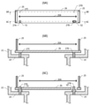
図4は、チェンバ15及び架台11の平面図である。図5A及び図5Bは、それぞれ図4の一点鎖線5A-5A及び一点鎖線5B-5Bにおける断面図である。平面視において、光軸20Aの方向に関してブロワ室17の両側に底板19が設けられている。チェンバ15の2つの底板19の各々から、光軸20Aから遠ざかる二方向に被支持部32が突出している。被支持部32は、チェンバ15と一体的に形成してもよいし、被支持部32をボルト等でチェンバ15に取り付けて固定してもよい。「一体的に形成」とは、分離不可能に形成することを意味し、例えば溶接等による接続や、単一部材で形成すること等を意味する。なお、底板19の一部分を被支持部32として利用してもよい。2つの底板19の各々に設けられた2つの被支持部32は、光軸方向に関して同じ位置に配置されている。すなわち、4個の被支持部32が、長方形の4個の頂点に対応する位置に配置されている。
Next, a structure for supporting the chamber 15 on the gantry 11 will be described with reference to FIGS. 4 to 5B.
FIG. 4 is a plan view of the chamber 15 and the gantry 11. 5A and 5B are cross-sectional views taken along the alternate long and short dash line 5A-5A and the alternate long and short dash line 5B-5B of FIG. 4, respectively. In a plan view, bottom plates 19 are provided on both sides of the blower chamber 17 with respect to the direction of the optical axis 20A. The supported portion 32 projects from each of the two bottom plates 19 of the chamber 15 in two directions away from the optical axis 20A. The supported portion 32 may be integrally formed with the chamber 15, or the supported portion 32 may be attached to and fixed to the chamber 15 with bolts or the like. "Integrally formed" means that it is formed inseparably, for example, it is connected by welding or the like, or it is formed by a single member. A part of the bottom plate 19 may be used as the supported portion 32. The two supported portions 32 provided on each of the two bottom plates 19 are arranged at the same position in the optical axis direction. That is, the four supported portions 32 are arranged at positions corresponding to the four vertices of the rectangle.

架台11の4個の支持部31が、平面視において被支持部32のそれぞれと重なる位置に設けられている。支持部31は、架台11の、光軸20Aに平行な2本の枠から光軸20Aに向かって突出している。支持部31は、架台11と一体的に形成してもよいし、支持部31をボルト等で架台11に取り付けて固定してもよい。なお、架台11の一部分を支持部31として利用してもよい。支持部31の各々は、被支持部32からの荷重を受け止める。すなわち、チェンバ15は4箇所で架台11に支持されている。支持部31と被支持部32との間に摩擦力低減部材36(図5A、図5B)が挿入されている。すなわち、チェンバ15を支持する箇所において、架台11は摩擦力低減部材36を介してチェンバ15を支持している。摩擦力低減部材36は、摩擦力低減部材36を配置せず、支持部31と被支持部32とが直接接触する場合よりも摩擦力を低減させる。摩擦力低減部材36として、例えばポリテトラフルオロエチレン(PTFE)等が用いられる。 The four support portions 31 of the gantry 11 are provided at positions overlapping each of the supported portions 32 in a plan view. The support portion 31 projects from the two frames of the gantry 11 parallel to the optical axis 20A toward the optical axis 20A. The support portion 31 may be integrally formed with the gantry 11, or the support portion 31 may be attached to the gantry 11 with bolts or the like and fixed. A part of the gantry 11 may be used as the support portion 31. Each of the support portions 31 receives the load from the supported portion 32. That is, the chamber 15 is supported by the gantry 11 at four points. A frictional force reducing member 36 (FIGS. 5A and 5B) is inserted between the supporting portion 31 and the supported portion 32. That is, at the position where the chamber 15 is supported, the gantry 11 supports the chamber 15 via the frictional force reducing member 36. The frictional force reducing member 36 does not arrange the frictional force reducing member 36, and reduces the frictional force as compared with the case where the supporting portion 31 and the supported portion 32 are in direct contact with each other. As the frictional force reducing member 36, for example, polytetrafluoroethylene (PTFE) or the like is used.

4個の被支持部32のうち1つの被支持部32(図4において左下の被支持部32)は、ボルト33で支持部31に固定されている。これにより、被支持部32の、支持部31に対する水平方向の位置が拘束される。すなわち、1箇所において、架台11に対するチェンバ15の水平方向の位置が拘束されている。なお、架台11に対してチェンバ15の水平方向の位置が拘束されている箇所においては、チェンバ15と架台11との間に摩擦力低減部材36を配置しなくてもよい。 One of the four supported portions 32, the supported portion 32 (supported portion 32 at the lower left in FIG. 4), is fixed to the support portion 31 with bolts 33. As a result, the position of the supported portion 32 in the horizontal direction with respect to the supported portion 31 is constrained. That is, the horizontal position of the chamber 15 with respect to the gantry 11 is constrained at one place. In the place where the horizontal position of the chamber 15 is constrained with respect to the gantry 11, the frictional force reducing member 36 may not be arranged between the chamber 15 and the gantry 11.

架台11に対してチェンバ15の水平方向の位置が拘束されている箇所以外の3箇所に、架台11に固定された側壁部31A及び天蓋部31B(図5A、図5B)が設けられている。側壁部31Aは、被支持部32の先端面に対向し、天蓋部31Bは、被支持部32の上面に対向する。図4において、天蓋部31Bは支持部31とほぼ重なっている。側壁部31A及び天蓋部31Bは、架台11と一体的に形成してもよいし、ボルト等で架台11に取り付けて固定してもよい。 Side wall portions 31A and canopy portions 31B (FIGS. 5A and 5B) fixed to the gantry 11 are provided at three locations other than the locations where the horizontal positions of the chamber 15 are constrained with respect to the gantry 11. The side wall portion 31A faces the tip surface of the supported portion 32, and the canopy portion 31B faces the upper surface of the supported portion 32. In FIG. 4, the canopy portion 31B substantially overlaps with the support portion 31. The side wall portion 31A and the canopy portion 31B may be integrally formed with the gantry 11, or may be attached to the gantry 11 with bolts or the like and fixed.

被支持部32と天蓋部31Bとの間に、コイルバネ等の弾性部材34が配置されている。弾性部材34は、被支持部32を支持部31に対して、荷重が加わる方向と同一の方向に押し付ける。これにより、チェンバ15が架台11に向かって押し付けられる。 An elastic member 34 such as a coil spring is arranged between the supported portion 32 and the canopy portion 31B. The elastic member 34 presses the supported portion 32 against the supported portion 31 in the same direction as the load is applied. As a result, the chamber 15 is pressed toward the gantry 11.

光軸20Aから見て、支持部31に固定された被支持部32とは反対側に配置されている2つの被支持部32(図4において上側、図5A及び図5において右側の被支持部32)においては、被支持部32の先端面と側壁部31Aとの間に空隙が確保されている。このため、被支持部32は支持部31に対して、光軸20Aと平行な方向及び直交する方向の二方向に移動可能である。すなわち、2箇所において、チェンバ15が架台11に対して水平な二方向に移動可能に支持されている。 Two supported portions 32 (upper side in FIG. 4, right side in FIGS. 5A and 5) arranged on the opposite side of the supported portion 32 fixed to the support portion 31 when viewed from the optical axis 20A. In 32), a gap is secured between the front end surface of the supported portion 32 and the side wall portion 31A. Therefore, the supported portion 32 can move with respect to the support portion 31 in two directions, a direction parallel to the optical axis 20A and a direction orthogonal to the optical axis 20A. That is, at two locations, the chamber 15 is movably supported in two directions horizontal to the gantry 11.

光軸20Aから見て、支持部31に固定された被支持部32と同じ側に配置されている被支持部32(図4において右下、図5Bにおいて左側の被支持部32)においては、被支持部32の先端面と側壁部31Aとの間に摩擦力低減部材36が挟まれている。光軸20Aの方向に関してこの被支持部32と同じ位置に配置されているもう1つの被支持部32においては、被支持部32の先端面と側壁部31Aとの間に、弾性部材35が配置されている。弾性部材35は、被支持部32を、光軸20Aを挟んで反対側の側壁部31Aに押し付けている。なお、被支持部32の先端面と弾性部材35との間に、摩擦力低減部材36が配置されている。 The supported portion 32 (lower right in FIG. 4 and the left supported portion 32 in FIG. 5B) arranged on the same side as the supported portion 32 fixed to the support portion 31 when viewed from the optical axis 20A. The frictional force reducing member 36 is sandwiched between the tip surface of the supported portion 32 and the side wall portion 31A. In another supported portion 32 arranged at the same position as the supported portion 32 in the direction of the optical axis 20A, the elastic member 35 is arranged between the tip surface of the supported portion 32 and the side wall portion 31A. Has been done. The elastic member 35 presses the supported portion 32 against the side wall portion 31A on the opposite side of the optical axis 20A. The frictional force reducing member 36 is arranged between the tip surface of the supported portion 32 and the elastic member 35.

光軸20Aから見て、支持部31に固定された被支持部32と同じ側に配置されている被支持部32(図5Bにおいて左側の被支持部32)の先端面と側壁部31Aとの間に空隙は確保されていない。このため、この被支持部32は、支持部31に対して、光軸20Aに直交する方向の位置が拘束される。なお、光軸20Aに平行な方向に関しては、被支持部32は自由に移動可能である。すなわち、架台11に対するチェンバ15の水平方向の位置が拘束されている箇所を中心としてチェンバ15が水平面内で回転方向に変位しないように、1箇所において、チェンバ15の回転方向の位置が拘束されている。 The front end surface and the side wall portion 31A of the supported portion 32 (supported portion 32 on the left side in FIG. 5B) arranged on the same side as the supported portion 32 fixed to the support portion 31 when viewed from the optical axis 20A. No gap is secured between them. Therefore, the position of the supported portion 32 in the direction orthogonal to the optical axis 20A is constrained with respect to the supporting portion 31. The supported portion 32 can move freely in the direction parallel to the optical axis 20A. That is, the position of the chamber 15 in the rotational direction is constrained at one place so that the chamber 15 does not displace in the horizontal direction in the horizontal plane around the position where the horizontal position of the chamber 15 with respect to the gantry 11 is constrained. There is.

次に、図6A~図6Cを参照して、共振器ベース26をチェンバ15に支持する構造について説明する。
図6Aは、共振器ベース26の平面図であり、図6B及び図6Cは、それぞれ図6Aの一点鎖線6B-6B及び一点鎖線6C-6Cにおける断面図である。共振器ベース26は、光軸20Aの方向に長い平板である。共振器ベース26の両端近傍の上面に共振器ミラー25が固定されている。
Next, the structure in which the resonator base 26 is supported by the chamber 15 will be described with reference to FIGS. 6A to 6C.
6A is a plan view of the resonator base 26, and FIGS. 6B and 6C are cross-sectional views of the alternate long and short dash line 6B-6B and 6C-6C, respectively. The resonator base 26 is a flat plate long in the direction of the optical axis 20A. The resonator mirror 25 is fixed to the upper surface near both ends of the resonator base 26.

平面視において共振器ベース26に内包される位置に、4本の光共振器支持部材27A、27B、27C、27Dが配置されている。光共振器支持部材27A、27Bの各々は段付きピンであり、平面視において光軸20Aから見て同じ側に配置されている。光共振器支持部材27A、27Bの中心を通過する直線は、光軸20Aと平行である。他の2つの光共振器支持部材27C、27Dは、段差が設けられていないピンであり、それぞれ平面視において光軸20Aに関して光共振器支持部材27A、27Bの線対称の位置に配置されている。すなわち、4個の光共振器支持部材27A~27Dは、長方形の4つの頂点に対応する位置に配置されている。4個の光共振器支持部材27A~27Dの下端は、底板19に埋め込まれて底板19に固定されている。 Four optical resonator support members 27A, 27B, 27C, and 27D are arranged at positions included in the resonator base 26 in a plan view. Each of the optical resonator support members 27A and 27B is a stepped pin, and is arranged on the same side of the optical axis 20A in a plan view. The straight line passing through the center of the optical resonator support members 27A and 27B is parallel to the optical axis 20A. The other two optical resonator support members 27C and 27D are pins having no step, and are arranged at positions of line symmetry of the optical resonator support members 27A and 27B with respect to the optical axis 20A in a plan view, respectively. .. That is, the four optical resonator support members 27A to 27D are arranged at positions corresponding to the four vertices of the rectangle. The lower ends of the four optical resonator support members 27A to 27D are embedded in the bottom plate 19 and fixed to the bottom plate 19.

共振器ベース26に、円形孔51及び長孔52が設けられている。円形孔51及び長孔52は、それぞれ、平面視において光共振器支持部材27A、27Bに対応する位置に配置されている。長孔52は、平面視において光軸20Aに平行な方向に長い形状を持つ。光共振器支持部材27A、27Bのそれぞれの段差より上方の部分が、円形孔51及び長孔52に挿入されている。共振器ベース26は、光共振器支持部材27A、27Bの段差部分、及び光共振器支持部材27C、27Dの上端面によって、荷重が加わる方向に支持されている。 The resonator base 26 is provided with a circular hole 51 and an elongated hole 52. The circular hole 51 and the elongated hole 52 are arranged at positions corresponding to the optical resonator support members 27A and 27B in a plan view, respectively. The elongated hole 52 has a long shape in a direction parallel to the optical axis 20A in a plan view. A portion of the optical resonator support members 27A and 27B above the step is inserted into the circular hole 51 and the elongated hole 52. The resonator base 26 is supported in a direction in which a load is applied by the stepped portions of the optical resonator support members 27A and 27B and the upper end surfaces of the optical resonator support members 27C and 27D.

共振器ベース26のうち円形孔51の周囲の部分は、光共振器支持部材27Aに対して水平面内の位置が拘束されている。長孔52に挿入された光共振器支持部材27Bは、共振器ベース26に対して光軸20Aに平行な一次元方向に移動可能である。光共振器支持部材27C、27Dは、共振器ベース26に対して水平面内の二方向に移動可能である。すなわち、共振器ベース26は、チェンバ15に対して1か所において水平方向の位置が拘束され、他の3か所においては水平方向の位置が拘束されていない。 The portion of the resonator base 26 around the circular hole 51 is constrained in position in the horizontal plane with respect to the optical resonator support member 27A. The optical resonator support member 27B inserted into the elongated hole 52 is movable in a one-dimensional direction parallel to the optical axis 20A with respect to the resonator base 26. The optical resonator support members 27C and 27D can move in two directions in a horizontal plane with respect to the resonator base 26. That is, the resonator base 26 is constrained in the horizontal position at one place with respect to the chamber 15, and is not constrained in the horizontal position at the other three places.

次に、図7A及び図7Bに示した比較例と比較しながら、上記実施例の優れた効果について説明する。 Next, the excellent effects of the above-mentioned examples will be described while comparing with the comparative examples shown in FIGS. 7A and 7B.

図7A及び図7Bは、それぞれ比較例によるレーザ装置の概略平面図及び概略断面図である。比較例においては、チェンバ15の4個の被支持部32のすべてが、架台11の4個の支持部31にボルト33で固定されている。図7Bにおいて、支持部31と被支持部32とのペアを模式的に三角形30で表している。レーザ発振器12を動作させると、放電によってレーザ媒質ガスの温度が上昇する。その結果、チェンバ15の温度も上昇し、チェンバ15が熱膨張する。図7A及び図7Bにおいて、熱膨張後の各構成部分を破線で示している。なお、図7A及び図7Bでは理解を容易にするために、熱膨張による変形量を実際の変形量より極端に大きく示している。 7A and 7B are a schematic plan view and a schematic cross-sectional view of a laser apparatus according to a comparative example, respectively. In the comparative example, all of the four supported portions 32 of the chamber 15 are fixed to the four supporting portions 31 of the gantry 11 with bolts 33. In FIG. 7B, the pair of the support portion 31 and the supported portion 32 is schematically represented by a triangle 30. When the laser oscillator 12 is operated, the temperature of the laser medium gas rises due to the discharge. As a result, the temperature of the chamber 15 also rises, and the chamber 15 thermally expands. In FIGS. 7A and 7B, each component after thermal expansion is shown by a broken line. In addition, in FIGS. 7A and 7B, in order to facilitate understanding, the amount of deformation due to thermal expansion is shown to be extremely larger than the actual amount of deformation.

図3に示した断面において、放電領域24より下流側のレーザ媒質ガスの温度が、上流側のレーザ媒質ガスの温度より高くなる。このため、チェンバ15の2つの側面の温度上昇幅に差が生じ、チェンバ15の側面の熱膨張量にも差が生じる。このため、図7Aに示したように、チェンバ15の一方の側面(図7Aにおいて上側の側面)が、他方の側面より大きく膨張し、チェンバ15に変形が生じる。チェンバ15の変形により、架台11にも変形が生じる。 In the cross section shown in FIG. 3, the temperature of the laser medium gas on the downstream side of the discharge region 24 is higher than the temperature of the laser medium gas on the upstream side. Therefore, there is a difference in the temperature rise width between the two side surfaces of the chamber 15, and a difference in the amount of thermal expansion of the side surface of the chamber 15. Therefore, as shown in FIG. 7A, one side surface of the chamber 15 (the upper side surface in FIG. 7A) expands more than the other side surface, and the chamber 15 is deformed. Due to the deformation of the chamber 15, the gantry 11 is also deformed.

架台11に変形が生じると、架台11に支持されているチェンバ15の底板19の姿勢が変化する。底板19に支持されている共振器ベース26の姿勢も変化し、その結果、光軸20Aの位置及び方向が変化する。光軸20Aの位置及び方向の変化に応じて、レーザ発振器12(図1)から出力されるレーザビームの経路が変化するため、ビーム整形光学系81(図1)へのレーザビームの入射位置が初期の位置からずれる。これにより、加工対象物90の表面におけるビームプロファイルが崩れ、加工不良が生じやすくなる。 When the gantry 11 is deformed, the posture of the bottom plate 19 of the chamber 15 supported by the gantry 11 changes. The posture of the resonator base 26 supported by the bottom plate 19 also changes, and as a result, the position and direction of the optical axis 20A change. Since the path of the laser beam output from the laser oscillator 12 (FIG. 1) changes according to the change in the position and direction of the optical axis 20A, the incident position of the laser beam on the beam shaping optical system 81 (FIG. 1) is changed. It deviates from the initial position. As a result, the beam profile on the surface of the object to be machined 90 is broken, and machining defects are likely to occur.

これに対して上記実施例では、4個の被支持部32(図4)のうち1個のみが、支持部31に固定されており、残りの3個の被支持部32は、支持部31に対して水平方向に移動可能である。すなわち、チェンバ15が支持されている4箇所のうち1箇所において、架台11に対するチェンバ15の水平方向の位置が拘束されており、残りの3箇所においては、架台11に対してチェンバ15が水平方向に移動可能に支持されている。さらに、被支持部32と支持部31との間に摩擦力低減部材36が配置されているため、支持部31に対して被支持部32が水平方向に移動しやすい。このため、チェンバ15が熱膨張したときの架台11の変形が抑制される。架台11の変形が生じにくいため、架台11の変形に起因する光軸20Aのずれも生じにくい。 On the other hand, in the above embodiment, only one of the four supported portions 32 (FIG. 4) is fixed to the supported portion 31, and the remaining three supported portions 32 are the supported portions 31. It can move horizontally with respect to. That is, the horizontal position of the chamber 15 with respect to the gantry 11 is constrained at one of the four locations where the chamber 15 is supported, and the chamber 15 is horizontal with respect to the gantry 11 at the remaining three locations. It is supported to be movable. Further, since the frictional force reducing member 36 is arranged between the supported portion 32 and the supported portion 31, the supported portion 32 easily moves in the horizontal direction with respect to the supported portion 31. Therefore, the deformation of the gantry 11 when the chamber 15 is thermally expanded is suppressed. Since the gantry 11 is less likely to be deformed, the optical axis 20A is less likely to be displaced due to the deformation of the gantry 11.

また、図4において右下の被支持部32は、光軸20Aに対して平行な方向に関しては移動可能であるが、光軸20Aに対して直交する方向の位置は拘束されている。このため、支持部31に固定された被支持部32を中心とした回転方向の姿勢を拘束することができる。 Further, in FIG. 4, the lower right supported portion 32 is movable in the direction parallel to the optical axis 20A, but the position in the direction orthogonal to the optical axis 20A is constrained. Therefore, it is possible to restrain the posture in the rotational direction about the supported portion 32 fixed to the support portion 31.

さらに、支持部31に固定されている被支持部32(図4)と、光軸20Aに対して直交する方向への位置が拘束されている被支持部32とを結ぶ直線が、光軸20Aに平行である。このため、チェンバ15が熱膨張しても、チェンバ15の回転方向の姿勢は実質的に変化しない。 Further, a straight line connecting the supported portion 32 fixed to the support portion 31 (FIG. 4) and the supported portion 32 whose position in the direction orthogonal to the optical axis 20A is constrained is the optical axis 20A. Is parallel to. Therefore, even if the chamber 15 thermally expands, the posture of the chamber 15 in the rotational direction does not substantially change.

被支持部32が支持部31に固定されていない箇所において、被支持部32が弾性部材34によって支持部31に押し付けられている。このため、チェンバ15の鉛直方向の位置が安定するという優れた効果が得られる。 The supported portion 32 is pressed against the supported portion 31 by the elastic member 34 at a position where the supported portion 32 is not fixed to the supported portion 31. Therefore, an excellent effect that the vertical position of the chamber 15 is stabilized can be obtained.

共振器ベース26(図6A~図6C)は、光共振器支持部材27Aで支持されている箇所においてのみ水平面内でチェンバ15に固定されており、他の光共振器支持部材27B、27C、27Dで支持されている箇所では、水平方向の移動が許容されている。このため、共振器ベース26は、チェンバ15の変形の影響を受けにくく、光軸20Aのずれも生じにくい。 The resonator base 26 (FIGS. 6A to 6C) is fixed to the chamber 15 in the horizontal plane only at a position supported by the optical resonator support member 27A, and other optical resonator support members 27B, 27C, 27D. Horizontal movement is allowed where it is supported by. Therefore, the resonator base 26 is not easily affected by the deformation of the chamber 15, and the optical axis 20A is not easily displaced.

また、共振器ベース26の、光共振器支持部材27Bで支持されている箇所は、光軸20Aに直交する方向の位置が拘束されている。このため、共振器ベース26の水平面内での回転方向の位置が拘束される。 Further, the position of the resonator base 26 supported by the optical resonator support member 27B is constrained in a position orthogonal to the optical axis 20A. Therefore, the position of the resonator base 26 in the horizontal plane in the horizontal direction is constrained.

実際に、上記実施例によるレーザ装置と、図7A~図7Bに示した比較例によるレーザ装置とのビーム経路の位置安定性について比較実験を行った。以下、比較実験の内容について説明する。 Actually, a comparative experiment was conducted on the position stability of the beam path between the laser apparatus according to the above embodiment and the laser apparatus according to the comparative examples shown in FIGS. 7A to 7B. The contents of the comparative experiment will be described below.

実施例によるレーザ装置と比較例によるレーザ装置とのそれぞれを、パルスの繰り返し周波数及び出力が異なる2つの発振条件で動作させた。チェンバの温度が安定した状態で、光共振器の出力端から一定の距離だけ離れた位置におけるビームスポットを検出し、2つの発振条件におけるビームスポットの位置のずれ量を計測した。パルスの繰り返し周波数が高く、出力も大きな条件で動作させた場合には、パルスの繰り返し周波数が低く、出力も低い条件で動作させた場合より、チェンバが高温になる。 The laser apparatus according to the embodiment and the laser apparatus according to the comparative example were operated under two oscillation conditions having different pulse repetition frequencies and outputs. With the temperature of the chamber stable, the beam spot was detected at a position separated from the output end of the optical resonator by a certain distance, and the amount of deviation of the position of the beam spot under the two oscillation conditions was measured. When the pulse repetition frequency is high and the output is also large, the chamber becomes hotter than when the pulse repetition frequency is low and the output is low.

本実施例によるレーザ装置におけるビームスポットのずれ量は、比較例によるレーザ装置におけるビームスポットのずれ量の1/4~1/3程度であった。この比較実験から、上記実施例による構造のレーザ装置のレーザビームの経路の位置は、チェンバの熱変形の影響を受けにくいことがわかる。 The amount of deviation of the beam spot in the laser apparatus according to the present embodiment was about 1/4 to 1/3 of the amount of deviation of the beam spot in the laser apparatus according to the comparative example. From this comparative experiment, it can be seen that the position of the laser beam path of the laser device having the structure according to the above embodiment is not easily affected by the thermal deformation of the chamber.

次に、上記実施例の変形例について説明する。
上記実施例では、チェンバ15の被支持部32、及び架台11の支持部31を、それぞれ4個にしているが、2個にしてもよいし、3個または5個以上にしてもよい。すなわち、架台11がチェンバ15を2箇所、3箇所、または5箇所以上で支持してもよい。チェンバ15を2箇所で支持する場合には、例えば、図4において左側に位置する2つの被支持部32を結ぶ細長い領域でチェンバ15を支持し、右側に位置する2つの被支持部32を結ぶ細長い領域でチェンバ15を支持するとよい。この場合、架台11の対応する支持部31も、平面視において細長い形状になる。チェンバ15を支持する左側の細長い領域の一方の端部近傍の1箇所でチェンバ15を架台11にボルト等で固定するとよい。チェンバ15を支持する左側の細長い領域のうち、ボルト等で固定されていない領域においては、架台11に対するチェンバ15の水平方向の位置が拘束されない。また、チェンバ15を支持する右側の細長い領域においては、その全域でチェンバ15が架台11に対して水平方向に移動可能である。
Next, a modification of the above embodiment will be described.
In the above embodiment, the number of the supported portion 32 of the chamber 15 and the number of the supporting portions 31 of the gantry 11 are four, but the number may be two, three, or five or more. That is, the gantry 11 may support the chamber 15 at two, three, or five or more locations. When the chamber 15 is supported at two points, for example, the chamber 15 is supported by an elongated region connecting the two supported portions 32 located on the left side in FIG. 4, and the two supported portions 32 located on the right side are connected. It is advisable to support the chamber 15 in an elongated region. In this case, the corresponding support portion 31 of the gantry 11 also has an elongated shape in a plan view. It is preferable to fix the chamber 15 to the gantry 11 with bolts or the like at one place near one end of the elongated region on the left side that supports the chamber 15. Of the elongated region on the left side that supports the chamber 15, the horizontal position of the chamber 15 with respect to the gantry 11 is not constrained in the region that is not fixed by bolts or the like. Further, in the elongated region on the right side supporting the chamber 15, the chamber 15 can move horizontally with respect to the gantry 11 in the entire area.

チェンバ15を3箇所で支持する場合には、例えば、図4において左側の2つの被支持部32を結ぶ1つの細長い領域と、右側の2つの被支持部32とでチェンバ15を支持するとよい。または、図4において右側の2つの被支持部32を結ぶ1つの細長い領域と、左側の2つの被支持部32とでチェンバ15を支持するとよい。チェンバ15を5箇所以上で支持する場合には、例えば、図4において上側または下側の2つの被支持部32の間に、新たに被支持部及び支持部を設けるとよい。 When the chamber 15 is supported at three points, for example, in FIG. 4, one elongated region connecting the two supported portions 32 on the left side and the two supported portions 32 on the right side may support the chamber 15. Alternatively, the chamber 15 may be supported by one elongated region connecting the two supported portions 32 on the right side in FIG. 4 and the two supported portions 32 on the left side. When the chamber 15 is supported at five or more points, for example, it is preferable to newly provide a supported portion and a supported portion between the two supported portions 32 on the upper side or the lower side in FIG.

すなわち、架台11がチェンバ15を複数箇所で支持するようにしてもよい。この場合、複数の被支持部32のうち1つの被支持部32を、対応する支持部31に対して水平方向の位置が拘束された固定被支持部とすればよい。すなわち、1箇所において、架台11に対するチェンバ15の水平方向の位置を拘束すればよい。 That is, the gantry 11 may support the chamber 15 at a plurality of locations. In this case, one of the plurality of supported portions 32 may be a fixed supported portion 32 whose position in the horizontal direction is constrained with respect to the corresponding support portion 31. That is, the horizontal position of the chamber 15 with respect to the gantry 11 may be constrained at one location.

複数の被支持部32のうち固定被支持部以外の被支持部32は、対応する支持部31に対して水平方向に移動可能にすればよい。すなわち、チェンバ15の水平方向の位置が拘束された支持箇所以外の支持箇所においては、チェンバ15が架台11に対して水平方向に移動可能にすればよい。固定被支持部以外の複数の被支持部32のうち1つの被支持部32においては、対応する支持部31に対して、固定被支持部を中心とした水平面内における回転方向の位置を拘束する構成にするとよい。すなわち、1つの支持箇所においては、水平面内におけるチェンバ15の、固定被支持部を中心とした回転方向の位置を拘束するとよい。 Of the plurality of supported portions 32, the supported portions 32 other than the fixed supported portions may be movable in the horizontal direction with respect to the corresponding supported portions 31. That is, the chamber 15 may be movable in the horizontal direction with respect to the gantry 11 at the support points other than the support points where the horizontal position of the chamber 15 is constrained. In one of the plurality of supported portions 32 other than the fixed supported portion 32, the supported portion 32 restrains the position in the horizontal plane about the fixed supported portion in the horizontal plane with respect to the corresponding support portion 31. It is good to configure it. That is, at one support location, the position of the chamber 15 in the horizontal plane in the rotational direction with respect to the fixed supported portion may be constrained.

上記実施例は例示であり、本発明は上述の実施例に制限されるものではない。例えば、種々の変更、改良、組み合わせ等が可能なことは当業者に自明であろう。 The above examples are examples, and the present invention is not limited to the above examples. For example, it will be obvious to those skilled in the art that various changes, improvements, combinations, etc. are possible.

10 レーザ装置
11 架台
12 レーザ発振器
13 架台脚
15 チェンバ
16 光学室
17 ブロワ室
18 上下仕切り板
18A、18B 開口
19 底板
20 光共振器
20A 光軸
21 放電電極
22、23 放電電極支持部材
24 放電領域
25 共振器ミラー
26 共振器ベース
27、27A、27B、27C、27D 光共振器支持部材
28 光透過窓
29 ブロワ
31 支持部
31A 側壁部
31B 天蓋部
32 被支持部
33 ボルト
34、35 弾性部材
36 摩擦力低減部材
40 仕切り板
41 第1ガス流路
42 第2ガス流路
43 熱交換器
44 流出穴
45 フィルタ
51 円形孔
52 長孔
80 加工装置
81 ビーム整形光学系
82 ステージ
90 加工対象物
100 共通ベース
10 Laser device 11 Stand 12 Laser oscillator 13 Stand base 15 Chamber 16 Optical chamber 17 Blower chamber 18 Upper and lower partition plates 18A, 18B Opening 19 Bottom plate 20 Optical cavity 20A Optical axis 21 Discharge electrode 22, 23 Discharge electrode support member 24 Discharge region 25 Resonator mirror 26 Resonator base 27, 27A, 27B, 27C, 27D Optical resonator support member 28 Light transmission window 29 Blower 31 Support part 31A Side wall part 31B Canopy part 32 Supported part 33 Bolt 34, 35 Elastic member 36 Friction force Reduction member 40 Partition plate 41 1st gas flow path 42 2nd gas flow path 43 Heat exchanger 44 Outflow hole 45 Filter 51 Circular hole 52 Long hole 80 Processing device 81 Beam shaping optical system 82 Stage 90 Processing target 100 Common base

Claims (5)

レーザ媒質ガス及び光共振器を収容するチェンバと、
前記チェンバを支持する架台と
を有し、
前記チェンバは、1箇所で、前記架台に対する前記チェンバの水平方向の位置が拘束されており、
前記架台に対する前記チェンバの水平方向の位置が拘束されている箇所以外では、前記チェンバが前記架台に対して水平方向に移動可能に支持されているレーザ装置。
A chamber that houses the laser medium gas and the optical resonator,
It has a stand to support the chamber and
The chamber is constrained in one place by the horizontal position of the chamber with respect to the gantry.
A laser device in which the chamber is supported so as to be movable in the horizontal direction with respect to the gantry, except where the horizontal position of the chamber with respect to the gantry is constrained.
さらに、前記チェンバが前記架台に対して水平方向に移動可能に支持されている箇所において、荷重が加わる方向と同一の方向に前記チェンバを押し付ける弾性部材を有する請求項1に記載のレーザ装置。 The laser device according to claim 1, further comprising an elastic member that presses the chamber in the same direction as the load is applied at a position where the chamber is movably supported in a horizontal direction with respect to the gantry. 前記チェンバが前記架台に対して水平方向に移動可能に支持されている箇所において、前記架台は、摩擦力を低減させる摩擦力低減部材を介して前記チェンバを支持している請求項1または2に記載のレーザ装置。 According to claim 1 or 2, where the chamber is supported so as to be movable in the horizontal direction with respect to the gantry, the gantry supports the chamber via a frictional force reducing member that reduces the frictional force. The laser device described. 前記チェンバが前記架台に対して水平方向に移動可能に支持されている箇所のうち1つの箇所において、前記架台に対する前記チェンバの水平方向の位置が拘束されている箇所を中心とした水平面内における前記チェンバの回転方向の位置が拘束されている請求項1乃至3のいずれか1項に記載のレーザ装置。 The said in a horizontal plane centered on a place where the horizontal position of the chamber with respect to the pedestal is constrained at one of the places where the chamber is movably supported in the horizontal direction with respect to the pedestal. The laser device according to any one of claims 1 to 3, wherein the position of the chamber in the rotational direction is constrained. 前記光共振器は、
一対の共振器ミラーと、
前記チェンバに支持され、前記一対の共振器ミラーを固定する共振器ベースと
を有し
前記共振器ベースは、3個以上の複数の箇所で荷重が加わる方向に支持され、支持された複数の箇所のうち1か所においては水平方向の位置が拘束され、他の複数の箇所においては、水平方向の位置が拘束されていない請求項1乃至4のいずれか1項に記載のレーザ装置。
The optical resonator is
A pair of resonator mirrors and
It has a resonator base that is supported by the chamber and fixes the pair of resonator mirrors, and the resonator base is supported and supported in a direction in which a load is applied at a plurality of three or more locations. The laser device according to any one of claims 1 to 4, wherein the horizontal position is constrained in one of the locations, and the horizontal position is not constrained in the other plurality of locations.
JP2020116378A 2020-07-06 2020-07-06 Laser device Pending JP2022014176A (en)

Priority Applications (4)

Application Number Priority Date Filing Date Title
JP2020116378A JP2022014176A (en) 2020-07-06 2020-07-06 Laser device
KR1020210078436A KR20220005392A (en) 2020-07-06 2021-06-17 Laser apparatus
TW110122576A TWI834977B (en) 2020-07-06 2021-06-21 laser device
CN202110706451.7A CN113904204A (en) 2020-07-06 2021-06-24 Laser device

Applications Claiming Priority (1)

Application Number Priority Date Filing Date Title
JP2020116378A JP2022014176A (en) 2020-07-06 2020-07-06 Laser device

Publications (1)

Publication Number Publication Date
JP2022014176A true JP2022014176A (en) 2022-01-19

Family

ID=79187507

Family Applications (1)

Application Number Title Priority Date Filing Date
JP2020116378A Pending JP2022014176A (en) 2020-07-06 2020-07-06 Laser device

Country Status (3)

Country Link
JP (1) JP2022014176A (en)
KR (1) KR20220005392A (en)
CN (1) CN113904204A (en)

Family Cites Families (6)

* Cited by examiner, † Cited by third party
Publication number Priority date Publication date Assignee Title
JPH02105478A (en) 1988-10-14 1990-04-18 Toshiba Corp Laser oscillator
JP3768455B2 (en) * 2002-04-11 2006-04-19 三菱電機株式会社 Orthogonal excitation laser oscillator
WO2004105200A1 (en) * 2003-05-20 2004-12-02 Mitsubishi Denki Kabushiki Kaisha Laser transmitter
CN101606285B (en) * 2007-04-20 2011-04-13 三菱电机株式会社 Laser oscillator
JP2013048202A (en) * 2011-03-30 2013-03-07 Gigaphoton Inc Laser system
JP7359540B2 (en) * 2018-12-14 2023-10-11 住友重機械工業株式会社 gas laser equipment

Also Published As

Publication number Publication date
KR20220005392A (en) 2022-01-13
CN113904204A (en) 2022-01-07
TW202209772A (en) 2022-03-01

Similar Documents

Publication Publication Date Title
KR101994020B1 (en) Laser apparatus and extreme ultraviolet light generating device
JP7023573B2 (en) Laser oscillator
JP2022014176A (en) Laser device
TWI834977B (en) laser device
JP3835116B2 (en) Laser oscillator
JP3768455B2 (en) Orthogonal excitation laser oscillator
JP2006503337A (en) Beam splitter member holding device
TWI781658B (en) Aperture and Laser Oscillators
JP2022069129A (en) Laser device
TWI754854B (en) Optical resonator
JP7076914B2 (en) Folded optical resonator
JP2007067193A (en) Exposure device
JP3399865B2 (en) Optical base support structure of orthogonally pumped laser oscillator
JP2022013224A (en) Laser oscillator
JP6494543B2 (en) Multiple reflection cell
JPH06140692A (en) Laser oscillator
KR20220005983A (en) Beam shaping optical device and method for modifying roundness
JPS6024082A (en) Laser oscillator
JP2003046164A (en) Orthogonal excited laser oscillator
JP2002009378A (en) Laser device
JP2003037315A (en) Orthogonal pumping laser oscillator
JPH0821741B2 (en) Gas laser device
JPH04284988A (en) Laser beam machine

Legal Events

Date Code Title Description
A621 Written request for application examination

Free format text: JAPANESE INTERMEDIATE CODE: A621

Effective date: 20230519

A977 Report on retrieval

Free format text: JAPANESE INTERMEDIATE CODE: A971007

Effective date: 20240313

A131 Notification of reasons for refusal

Free format text: JAPANESE INTERMEDIATE CODE: A131

Effective date: 20240319