JP2015152467A - display control device, control method, program, and storage medium - Google Patents
display control device, control method, program, and storage medium Download PDFInfo
- Publication number
- JP2015152467A JP2015152467A JP2014027285A JP2014027285A JP2015152467A JP 2015152467 A JP2015152467 A JP 2015152467A JP 2014027285 A JP2014027285 A JP 2014027285A JP 2014027285 A JP2014027285 A JP 2014027285A JP 2015152467 A JP2015152467 A JP 2015152467A
- Authority
- JP
- Japan
- Prior art keywords
- display
- unit
- guidance
- area
- display control
- Prior art date
- Legal status (The legal status is an assumption and is not a legal conclusion. Google has not performed a legal analysis and makes no representation as to the accuracy of the status listed.)
- Pending
Links
- 238000000034 method Methods 0.000 title claims description 27
- 238000004364 calculation method Methods 0.000 claims description 33
- 238000003384 imaging method Methods 0.000 claims description 2
- 238000012986 modification Methods 0.000 description 20
- 230000004048 modification Effects 0.000 description 20
- 230000006870 function Effects 0.000 description 11
- 238000004891 communication Methods 0.000 description 10
- 230000001133 acceleration Effects 0.000 description 6
- 238000013500 data storage Methods 0.000 description 5
- 230000000052 comparative effect Effects 0.000 description 4
- 238000012545 processing Methods 0.000 description 4
- 238000013459 approach Methods 0.000 description 2
- 238000010586 diagram Methods 0.000 description 2
- 239000000284 extract Substances 0.000 description 2
- 239000004973 liquid crystal related substance Substances 0.000 description 2
- 230000003287 optical effect Effects 0.000 description 2
- 238000006243 chemical reaction Methods 0.000 description 1
- 230000006866 deterioration Effects 0.000 description 1
- 210000003128 head Anatomy 0.000 description 1
- 230000001771 impaired effect Effects 0.000 description 1
- 239000002184 metal Substances 0.000 description 1
- 210000001747 pupil Anatomy 0.000 description 1
Images


Landscapes
- Instructional Devices (AREA)
- Navigation (AREA)
- Instrument Panels (AREA)
Abstract
Description
本発明は、前方風景に重ねて案内情報の画像を表示する技術に関する。 The present invention relates to a technique for displaying an image of guidance information over a front landscape.
従来から、ヘッドアップディスプレイにおいて、車両の前方風景に見かけ上で重なるように案内情報を表示させる際に、案内情報の煩雑な表示により前方風景の視認性が損なわれるのを防ぐ技術が知られている。例えば、特許文献1には、検出した対象物の警報表示を行う場合、対象物が所定個数以下の場合には各対象物を強調する表示を行い、対象物が所定個数より大きい場合には表示される画像全体に対して1つの強調表示を行う点が記載されている。
Conventionally, in a head-up display, a technique for preventing the visibility of a front landscape from being impaired due to a complicated display of the guidance information when the guidance information is displayed so as to overlap the front landscape of the vehicle is known. Yes. For example, in
前方風景に重ねて案内情報を表示する際、前方風景中には、運転者に特に視認させる必要性が高いものが存在する場合がある。例えば、初めて運転者が訪れる目的地に向かう場合には、目的地付近において、目的地の視認性を特に確保する必要がある。しかしながら、特許文献1には、このような課題及び解決手段については、何ら開示されていない。
When the guidance information is displayed over the front scenery, there are cases where the driver needs to be particularly visually recognized by the driver. For example, when heading to a destination visited by a driver for the first time, it is necessary to particularly ensure the visibility of the destination in the vicinity of the destination. However,
本発明は、上記のような課題を解決するためになされたものであり、前方風景の視認性を好適に確保することが可能な表示制御装置を提供することを主な目的とする。 The present invention has been made to solve the above-described problems, and a main object of the present invention is to provide a display control device capable of suitably ensuring the visibility of a forward landscape.
請求項に記載の発明は、移動体の前方の風景を撮影した風景画像に重畳して、または前記風景に見かけ上で重なるように、案内情報を表示部の第一領域に表示させる表示制御部と、前記表示部上の前記移動体の移動に関しての案内をする地点である案内地の位置を算出する算出部と、を備え、前記表示制御部は、前記算出部が算出した前記表示部上の前記案内地の位置が前記第一領域と重なる場合には、前記案内情報の前記第一領域への表示を制限することを特徴とする。 The invention according to the claim provides a display control unit that displays guidance information in a first area of a display unit so as to be superimposed on a landscape image obtained by capturing a landscape in front of a moving object or to overlap the landscape in appearance. And a calculation unit that calculates a position of a guide point that is a point for guiding the movement of the moving body on the display unit, and the display control unit is arranged on the display unit calculated by the calculation unit. When the position of the guide area overlaps with the first area, display of the guidance information in the first area is limited.
また、請求項に記載の発明は、表示制御装置が実行する制御方法であって、移動体の前方の風景を撮影した風景画像に重畳して、または前記風景に見かけ上で重なるように、案内情報を表示部の第一領域に表示させる表示制御工程と、前記表示部上の前記移動体の移動に関しての案内をする地点である案内地の位置を算出する算出工程と、を備え、前記表示制御工程は、前記算出工程が算出した前記表示部上の前記案内地の位置が前記第一領域と重なる場合には、前記案内情報の前記第一領域への表示を制限することを特徴とする。 The invention described in the claims is a control method executed by the display control device, wherein the guidance is provided so as to be superimposed on a landscape image obtained by capturing a landscape in front of a moving object or to be superposed on the landscape. A display control step for displaying information on the first area of the display unit, and a calculation step for calculating a position of a guide point that is a point for guidance regarding movement of the moving body on the display unit, The control step restricts the display of the guidance information in the first region when the position of the guidance location on the display unit calculated by the calculation step overlaps the first region. .
また、請求項に記載の発明は、コンピュータが実行するプログラムであって、移動体の前方の風景を撮影した風景画像に重畳して、または前記風景に見かけ上で重なるように、案内情報を表示部の第一領域に表示させる表示制御部と、前記表示部上の前記移動体の移動に関しての案内をする地点である案内地の位置を算出する算出部として前記コンピュータを機能させ、前記表示制御部は、前記算出部が算出した前記表示部上の前記案内地の位置が前記第一領域と重なる場合には、前記案内情報の前記第一領域への表示を制限することを特徴とする。 The invention described in the claims is a program executed by a computer, and displays guidance information so as to be superimposed on a landscape image obtained by photographing a landscape in front of a moving object or to be superimposed on the landscape in appearance. The display control unit to be displayed in a first area of the unit, and the display control unit that causes the computer to function as a calculation unit that calculates a position of a guidance place that is a point to guide the movement of the moving body on the display unit. When the position of the guidance place on the display unit calculated by the calculation unit overlaps the first region, the unit restricts display of the guidance information on the first region.
本発明の1つの好適な実施形態では、表示制御装置は、移動体の前方の風景を撮影した風景画像に重畳して、または前記風景に見かけ上で重なるように、案内情報を表示部の第一領域に表示させる表示制御部と、前記表示部上の前記移動体の移動に関しての案内をする地点である案内地の位置を算出する算出部と、を備え、前記表示制御部は、前記算出部が算出した前記表示部上の前記案内地の位置が前記第一領域と重なる場合には、前記案内情報の前記第一領域への表示を制限する。 In one preferred embodiment of the present invention, the display control device displays the guidance information on the display unit so as to be superimposed on a landscape image obtained by capturing a landscape in front of the moving body or to overlap the landscape in appearance. A display control unit to be displayed in one area; and a calculation unit that calculates a position of a guide point that is a point for guidance regarding movement of the mobile object on the display unit, and the display control unit includes the calculation When the position of the guidance location on the display unit calculated by the unit overlaps the first area, the display of the guidance information in the first area is restricted.
上記表示制御装置は、表示制御部と、算出部とを備える。表示制御部は、移動体の前方の風景を撮影した風景画像に重畳して、または前記風景に見かけ上で重なるように、案内情報を表示部の第一領域に表示させる。ここで、「第一領域」は、案内情報を表示すべき領域であり、表示すべき案内情報が複数ある場合には、各案内情報に対してそれぞれ設けられる。算出部は、表示部上の移動体の移動に関しての案内をする地点である案内地の位置を算出する。そして、表示制御部は、算出部が算出した表示部上の案内地が第一領域と重なる場合には、案内情報の第一領域への表示を制限する。この態様により、表示制御装置は、風景中の目的地が案内情報の表示が重なる場合に、当該案内情報の表示を制限し、目的地の視認性を好適に確保することができる。 The display control device includes a display control unit and a calculation unit. The display control unit causes the guide information to be displayed in the first area of the display unit so as to be superimposed on the landscape image obtained by capturing the landscape in front of the moving body or to overlap the landscape in appearance. Here, the “first area” is an area where guidance information is to be displayed, and is provided for each piece of guidance information when there are a plurality of pieces of guidance information to be displayed. The calculation unit calculates the position of the guidance site, which is a point for guidance regarding the movement of the moving object on the display unit. And a display control part restrict | limits the display to the 1st area | region of guidance information, when the guidance place on the display part which the calculation part calculated overlaps with a 1st area | region. According to this aspect, the display control device can restrict the display of the guidance information when the destination in the landscape overlaps the display of the guidance information, and can appropriately ensure the visibility of the destination.
上記表示制御装置の一態様では、前記表示制御部は、前記算出部が算出した前記案内地が前記表示部上の前記第一領域と重なる場合には、前記第一領域と異なる第二領域へ表示する。このようにすることで、案内情報の表示を継続しつつ、目的地の視認性を好適に確保することができる。 In one aspect of the display control device, the display control unit moves to a second area different from the first area when the guide area calculated by the calculation section overlaps the first area on the display section. indicate. By doing in this way, the visibility of a destination can be suitably ensured, continuing display of guidance information.
上記表示制御装置の他の一態様では、前記表示制御部は、前記案内情報を複数種類表示し、かつ、前記算出部が算出した前記表示部上の前記案内地の位置が前記第一領域と重なる場合には、前記案内情報のうち、所定の種類の案内情報を前記第二領域へ表示する。この態様では、表示制御装置は、所定の種類の案内情報に限り、目的地と重なった場合に第一領域から第二領域に移動させる。これにより、表示制御装置は、例えば、表示位置を移動させても問題ない案内情報のみを移動させて表示を継続することができる。 In another aspect of the display control device, the display control unit displays a plurality of types of the guidance information, and the position of the guidance location on the display unit calculated by the calculation unit is the first region. In the case of overlapping, a predetermined type of guidance information among the guidance information is displayed in the second area. In this aspect, the display control apparatus moves only the predetermined type of guidance information from the first area to the second area when it overlaps the destination. Thereby, for example, the display control device can continue the display by moving only the guidance information that does not cause a problem even if the display position is moved.
上記表示制御装置の他の一態様では、表示制御装置は、前記移動体の現在位置を取得する現在位置取得部と、前記移動体の進行方向に関する情報を取得する進行方向取得部と、前記移動体の案内地に関する案内地情報を取得する案内地情報取得部と、をさらに備え、前記算出部は、前記現在位置と前記進行方向と前記案内地情報とに基づき、前記表示部上の前記案内地の位置を算出する。この態様により、算出部は、表示部上の案内地の位置を好適に算出することができる。 In another aspect of the display control device, the display control device includes a current position acquisition unit that acquires a current position of the moving body, a traveling direction acquisition unit that acquires information related to a traveling direction of the moving body, and the movement A guidance location information acquisition unit that acquires guidance location information related to the guidance location of the body, and the calculation unit is configured to provide the guidance on the display unit based on the current position, the traveling direction, and the guidance location information. Calculate the position of the ground. According to this aspect, the calculation unit can preferably calculate the position of the guide place on the display unit.
上記表示制御装置の他の一態様では、前記表示制御部は、前記現在位置と前記進行方向と前記案内地情報とに基づき、前記表示部上において、前記移動体の現在位置と前記案内地とを通る線分を定め、当該線分と前記第1領域とが重なる場合に、前記案内情報の前記第一領域への表示を制限する。この態様により、表示制御装置は、風景上の目的地と重なる案内情報を好適に特定することができる。 In another aspect of the display control device, the display control unit is configured to display, on the display unit, the current position of the mobile object and the guidance place based on the current position, the traveling direction, and the guidance place information. A line segment passing through the first area is defined, and when the line segment overlaps the first area, the display of the guidance information in the first area is limited. According to this aspect, the display control apparatus can suitably specify the guidance information that overlaps the destination on the landscape.
上記表示制御装置の他の一態様では、前記表示制御部は、前記現在位置と前記進行方向と前記案内地情報とに基づき、前記表示部上において、前記案内地が表示されていると推定される領域を定め、当該領域と前記第1領域とが重なる場合に、前記案内情報の前記第一領域への表示を制限する。この態様によっても、表示制御装置は、風景上の目的地と重なる案内情報を好適に特定することができる。 In another aspect of the display control device, the display control unit is presumed that the guide location is displayed on the display unit based on the current position, the traveling direction, and the guide location information. If the area overlaps with the first area, the display of the guidance information in the first area is restricted. Also according to this aspect, the display control device can suitably specify the guidance information that overlaps the destination on the landscape.
上記表示制御装置の他の一態様では、前記算出部は、前記移動体の前方を撮影する撮影部が生成した画像から前記目的地の表示領域を認識し、当該表示領域に対応する前記表示部上の領域を、前記案内地の位置として算出する。この態様によっても、算出部は、表示部上の案内地の位置を好適に算出することができる。 In another aspect of the display control device, the calculation unit recognizes a display area of the destination from an image generated by an imaging unit that images the front of the moving body, and the display unit corresponding to the display area The upper area is calculated as the position of the guide area. Also according to this aspect, the calculation unit can preferably calculate the position of the guide place on the display unit.
本発明の他の好適な実施形態では、表示制御装置が実行する制御方法であって、移動体の前方の風景を撮影した風景画像に重畳して、または前記風景に見かけ上で重なるように、案内情報を表示部の第一領域に表示させる表示制御工程と、前記表示部上の前記移動体の移動に関しての案内をする地点である案内地の位置を算出する算出工程と、を備え、前記表示制御工程は、前記算出部が算出した前記表示部上の前記案内地の位置が前記第一領域と重なる場合には、前記案内情報の前記第一領域への表示を制限する。表示制御装置は、この制御方法を実行することで、風景中の目的地が案内情報の表示が重なる場合に、当該案内情報の表示を制限し、目的地の視認性を好適に確保することができる。 In another preferred embodiment of the present invention, there is provided a control method executed by the display control device, which is superimposed on a landscape image obtained by capturing a landscape in front of a moving object or is apparently superimposed on the landscape. A display control step of displaying guide information on the first area of the display unit, and a calculation step of calculating a position of a guide point that is a point for guiding the movement of the moving body on the display unit, The display control step restricts the display of the guidance information in the first region when the position of the guidance location on the display unit calculated by the calculation unit overlaps the first region. By executing this control method, the display control device can restrict the display of the guidance information when the destination in the landscape overlaps the display of the guidance information, and suitably ensure the visibility of the destination. it can.
本発明のさらに別の実施形態では、コンピュータが実行するプログラムであって、移動体の前方の風景を撮影した風景画像に重畳して、または前記風景に見かけ上で重なるように、案内情報を表示部の第一領域に表示させる表示制御部と、前記表示部上の前記移動体の移動に関しての案内をする地点である案内地の位置を算出する算出部として前記コンピュータを機能させ、前記表示制御部は、前記算出部が算出した前記表示部上の前記案内地の位置が前記第一領域と重なる場合には、前記案内情報の前記第一領域への表示を制限する。コンピュータは、このプログラムを搭載して実行することで、風景中の目的地が案内情報の表示が重なる場合に、当該案内情報の表示を制限し、目的地の視認性を好適に確保することができる。好適には、上記プログラムは、記憶媒体に記憶される。 In still another embodiment of the present invention, a program executed by a computer displays guidance information so as to be superimposed on a landscape image obtained by capturing a landscape in front of a moving object or to overlap the landscape in appearance. The display control unit to be displayed in a first area of the unit, and the display control unit that causes the computer to function as a calculation unit that calculates a position of a guidance place that is a point to guide the movement of the moving body on the display unit. When the position of the guidance location on the display unit calculated by the calculation unit overlaps the first region, the unit restricts display of the guidance information on the first region. By installing and executing this program, the computer can restrict the display of the guidance information and suitably ensure the visibility of the destination when the guidance information display overlaps the destination in the landscape. it can. Preferably, the program is stored in a storage medium.
以下、図面を参照して本発明の好適な実施例について説明する。 Hereinafter, preferred embodiments of the present invention will be described with reference to the drawings.
[概略構成]
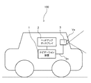
(1)システム構成
図1は、実施例に係る表示システム100の構成例を示す。図1に示すように、表示システム100は、車両Veに搭載され、ナビゲーション装置1と、ヘッドアップディスプレイ2と、カメラ3とを備える。なお、図1に示す構成に代えて、ヘッドアップディスプレイ2には、ナビゲーション装置1に相当する機能が組み込まれていてもよい。
[Schematic configuration]
(1) System Configuration FIG. 1 shows a configuration example of a
ナビゲーション装置1は、出発地から目的地までの経路案内を行う機能などを有する。本実施例では、ナビゲーション装置1は、ヘッドアップディスプレイ2の表示を制御する。ナビゲーション装置1は、例えば、車両Veに設置される据え置き型のナビゲーション装置、PND(Portable Navigation Device)、又はスマートフォンなどの携帯端末とすることができる。
The
ヘッドアップディスプレイ2は、走行予定の経路を示すルート画像、注意が必要な前方風景中の対象物を強調する画像、その他運転を補助する情報を表示する画像(これらを総称して「案内画像」とも呼ぶ。)を生成し、当該案内画像を運転者の目の位置(アイポイント)から虚像として視認させる装置である。ヘッドアップディスプレイ2には、表示すべき案内画像の情報がナビゲーション装置1から供給される。
The head-up
カメラ3は、車両Veの前方に向けて固定され、所定の間隔ごとに車両Veの前方を撮影した画像(「前方画像Im」とも呼ぶ。)を生成する。カメラ3は、生成した前方画像Imをナビゲーション装置1へ供給する。後述するように、ナビゲーション装置1は、前方画像Imに基づき、前方風景に含まれる運転者が注目すべき対象物(「対象物Obj」とも呼ぶ。)を検出する。本実施例では、ナビゲーション装置1は、対象物Objとして、車両Veの前方の歩行者、及び、消灯状態から点灯状態に切り替わった信号灯を検出する。
The
なお、ナビゲーション装置1がスマートフォンなどの携帯端末である場合、ナビゲーション装置1は、クレードルなどによって保持されても良い。この場合、ナビゲーション装置1は、クレードルなどを介して、ヘッドアップディスプレイ2と情報の授受を行うこととしても良い。
When the
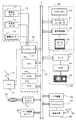
(2)ナビゲーション装置の構成
図2は、ナビゲーション装置1の構成を示す。図2に示すように、ナビゲーション装置1は、自立測位装置10、GPS受信機18、システムコントローラ20、ディスクドライブ31、データ記憶ユニット36、通信用インタフェース37、通信装置38、インタフェース39、表示ユニット40、音声出力ユニット50、及び入力装置60を備える。
(2) Configuration of Navigation Device FIG. 2 shows the configuration of the
自立測位装置10は、加速度センサ11、角速度センサ12及び距離センサ13を備える。加速度センサ11は、例えば圧電素子からなり、車両Veの加速度を検出し、加速度データを出力する。角速度センサ12は、例えば振動ジャイロからなり、車両Veの方向変換時における車両Veの角速度を検出し、角速度データ及び相対方位データを出力する。距離センサ13は、車両Veの車輪の回転に伴って発生されているパルス信号からなる車速パルスを計測する。
The
GPS受信機18は、複数のGPS衛星から、測位用データを含む下り回線データを搬送する電波19を受信する。測位用データは、緯度及び経度情報等から車両Veの絶対的な位置(「現在位置」とも呼ぶ。)を検出するために用いられる。
The
システムコントローラ20は、インタフェース21、CPU(Central Processing Unit)22、ROM(Read Only Memory)23及びRAM(Random Access Memory)24を含んでおり、ナビゲーション装置1全体の制御を行う。
The
例えば、システムコントローラ20は、ヘッドアップディスプレイ2が表示するための案内画像を生成する。本実施例では、システムコントローラ20は、車両Veの次の右左折地点での進行方向を指し示す矢印画像と、カメラ3から取得した前方画像Imに基づき認識した対象物Objを囲んだ強調画像とを、案内画像として生成する。そして、システムコントローラ20は、生成した案内画像をヘッドアップディスプレイ2に表示させる。システムコントローラ20は、本発明における「表示制御部」、「算出部」、「現在位置取得部」、「進行方向取得部」、「案内地情報取得部」及びプログラムを実行するコンピュータとして機能する。
For example, the
インタフェース21は、加速度センサ11、角速度センサ12及び距離センサ13並びにGPS受信機18とのインタフェース動作を行う。そして、これらから、車速パルス、加速度データ、相対方位データ、角速度データ、GPS測位データ、絶対方位データ等をシステムコントローラ20に入力する。CPU22は、システムコントローラ20全体を制御する。ROM23は、システムコントローラ20を制御する制御プログラム等が格納された図示しない不揮発性メモリ等を有する。RAM24は、入力装置60を介して使用者により予め設定された経路データ等の各種データを読み出し可能に格納したり、CPU22に対してワーキングエリアを提供したりする。
The
システムコントローラ20、CD−ROMドライブ又はDVD−ROMドライブなどのディスクドライブ31、データ記憶ユニット36、通信用インタフェース37、表示ユニット40、音声出力ユニット50及び入力装置60は、バスライン30を介して相互に接続されている。
A
ディスクドライブ31は、システムコントローラ20の制御の下、CD又はDVDといったディスク33から、音楽データ、映像データなどのコンテンツデータを読み出し、出力する。なお、ディスクドライブ31は、CD−ROMドライブ又はDVD−ROMドライブのうち、いずれか一方としてもよいし、CD及びDVDコンパチブルのドライブとしてもよい。
The
データ記憶ユニット36は、例えば、HDDなどにより構成され、地図データなどのナビゲーション処理に用いられる各種データを記憶するユニットである。地図データは、道路に相当するリンクと、道路の接続部分(交差点)に相当するノードとにより表された道路データや、施設に関する施設情報などを含む。
The
通信装置38は、例えば、FMチューナやビーコンレシーバ、携帯電話や専用の通信カードなどにより構成され、通信用インタフェース37を介して、VICS(登録商標、Vehicle Information Communication System)センタから配信される渋滞や交通情報などの道路交通情報、サーバ装置200から送信される情報、その他の情報を受信する。また、通信装置38は、システムコントローラ20が生成した制御信号や案内画像の情報等をヘッドアップディスプレイ2に送信する。
The
表示ユニット40は、システムコントローラ20の制御の下、各種表示データをディスプレイなどの表示装置に表示する。具体的には、システムコントローラ20は、データ記憶ユニット36から地図データを読み出す。表示ユニット40は、システムコントローラ20によってデータ記憶ユニット36から読み出された地図データなどを表示画面上に表示する。表示ユニット40は、バスライン30を介してCPU22から送られる制御データに基づいて表示ユニット40全体の制御を行うグラフィックコントローラ41と、VRAM(Video RAM)等のメモリからなり即時表示可能な画像情報を一時的に記憶するバッファメモリ42と、グラフィックコントローラ41から出力される画像データに基づいて、液晶、CRT(Cathode Ray Tube)等のディスプレイ44を表示制御する表示制御部43と、ディスプレイ44とを備える。ディスプレイ44は、画像表示部として機能し、例えば対角5〜10インチ程度の液晶表示装置等からなり、車内のフロントパネル付近に装着される。
The
音声出力ユニット50は、システムコントローラ20の制御の下、CD−ROMドライブ31又はDVD−ROM32、若しくはRAM24等からバスライン30を介して送られる音声デジタルデータのD/A(Digital to Analog)変換を行うD/Aコンバータ51と、D/Aコンバータ51から出力される音声アナログ信号を増幅する増幅器(AMP)52と、増幅された音声アナログ信号を音声に変換して車内に出力するスピーカ53とを備えて構成されている。
The
入力装置60は、各種コマンドやデータを入力するための、キー、スイッチ、ボタン、リモコン、音声入力装置等から構成されている。入力装置60は、車内に搭載された当該車載用電子システムの本体のフロントパネルやディスプレイ44の周囲に配置される。また、ディスプレイ44がタッチパネル方式の場合、ディスプレイ44の表示画面上に設けられたタッチパネルも入力装置60として機能する。
The
(3)ヘッドアップディスプレイの構成
図3は、本実施例に係るヘッドアップディスプレイ2を車室内に設置した状態を模式的に示す。図3は、車両Veの運転席を側方から見た図であり、運転者は車室内のシートに座っている。運転者の頭上には車両の外枠を形成するルーフ(板金)27があり、その下方には車室の内装である天井28がある。また、運転者の前方には車両のフロントガラス25及びサンバイザ29がある。図1では、サンバイザ29は、天井28に対して対向した状態で固定されている。
(3) Configuration of Head-Up Display FIG. 3 schematically shows a state in which the head-up
ヘッドアップディスプレイ2は、運転者の前方斜め上方向に設置される。ヘッドアップディスプレイ2は、主に、光源ユニット3が収容された本体部4と、コンバイナ5と、反射部7と、支持部8と、クリップ部9とを備える。
The head-up
本体部4に収容された光源ユニット3は、観察者に視認させる情報を示す中間像を構成する光(「表示光」とも呼ぶ。)を反射部7に向けて出射する。光源ユニット3の具体的な構成については、図4を参照して後述する。
The
コンバイナ5は、反射部7で生成された表示光が投影されると共に、その表示光を運転者のアイポイント「Pe」へ一部反射することで虚像「Iv」を観察者に視認させる光学部材である。なお、虚像Ivは矢印の先端が上方向を示す。支持部8は、本体部4からフロントガラス25の方向に延出し、コンバイナ5を支持する。支持部8は、例えば一対のアームであり、本体部4の両側面に一端がそれぞれ取り付けられ、他端によりコンバイナ5を挟持する。
The
反射部7は、中間像を生成する反射型の光学部材であり射出瞳拡大器(EPE)として機能する。反射部7は、例えば、光源ユニット3からの光が入射される面には複数のマイクロレンズが配列されたマイクロレンズアレイが形成され、かつ、マイクロレンズアレイと反対側の面に反射面が形成される。
The
クリップ部9は、天井28と対向する本体部4の上面に取り付けられ、サンバイザ29を挟み込んだ状態で本体部4をサンバイザ29に取り付ける。クリップ部9は、略J型に湾曲した板状の弾性体であり、サンバイザ29を狭持する方向に付勢する弾性力を有する。
The clip part 9 is attached to the upper surface of the main body part 4 facing the
(4)光源ユニットの構成
図4は、光源ユニット3の構成を概略的に示した図である。図4に示すように、光源ユニット3は、光源54と、制御部55と、通信部56とを有する。
(4) Configuration of Light Source Unit FIG. 4 is a diagram schematically showing the configuration of the
光源54は、例えば赤色、青色及び緑色の各色のレーザ光源を有し、制御部55の制御に基づき、コンバイナ5に照射させる表示光を出射する。そして、光源54及びコンバイナ5は、「表示部」として機能する。通信部56は、制御部55の制御に基づき、ナビゲーション処理に用いられる各種情報をナビゲーション装置1から受信する。
The light source 54 includes, for example, red, blue, and green laser light sources, and emits display light to be irradiated to the
制御部55は、CPU、CPUが実行する制御プログラムやデータなどを記憶するROM、CPUが動作する際のワークメモリとして各種データが逐次読み書きされるRAMなどを有し、ヘッドアップディスプレイ2の全般的な制御を行う。例えば、制御部65は、ナビゲーション装置1から送信された案内画像の表示光を光源54に出射させる。
The
[施設画像の表示]
次に、システムコントローラ20による案内画像の表示制御処理について説明する。概略的には、システムコントローラ20は、目的地に車両Veが近付いた場合、前方風景中の目的地と表示位置が重なる案内画像の表示を制限する。これにより、システムコントローラ20は、前方風景中の目的地の視認性が案内画像により悪化するのを好適に抑制する。
[Display of facility image]
Next, a guide image display control process by the
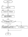
(1)処理概要
図5は、システムコントローラ20が実行する案内画像の表示処理を示すフローチャートである。システムコントローラ20は、図5に示すフローチャートの処理を、繰り返し実行する。
(1) Process Overview FIG. 5 is a flowchart showing a guide image display process executed by the
まず、システムコントローラ20は、カメラ3から前方画像Imを取得する(ステップS101)。そして、システムコントローラ20は、前方画像Imに基づき、対象物Objを認識する(ステップS102)。例えば、システムコントローラ20は、時系列により得られる前方画像Imに基づき、信号機の表示が切り替わった場合に、点灯状態となった信号灯を対象物Objとして認識する。また、システムコントローラ20は、公知の画像認識技術により、前方画像Im中から歩行者の表示領域を対象物Objとして抽出する。
First, the
次に、システムコントローラ20は、表示すべき案内画像及び案内画像の表示位置を決定する(ステップS103)。本実施例では、システムコントローラ20は、ステップS102で認識した対象物Objを強調表示する強調画像と、次の右左折地点での進行方向を示す矢印画像とを、表示すべき案内画像として認識する。そして、システムコントローラ20は、矢印画像の表示位置を、次の右左折地点と対応する位置に決定すると共に、強調画像の表示位置を、対象物Objを囲む位置に決定する。なお、強調画像の場合、システムコントローラ20は、例えば、前方画像Im中の対象物Objの位置と、コンバイナ5上で視認される対象物Objの位置との対応関係を示す情報を予め記憶しておき、当該情報を参照して、強調画像の表示位置を決定する。
Next, the
次に、システムコントローラ20は、現在位置と目的地までの距離が所定距離以内であるか否か判定する(ステップS104)。上述の所定距離は、目的地を視認可能な距離であるか否かを判断するための閾値であり、例えば50mに設定される。そして、システムコントローラ20は、現在位置と目的地までの距離が所定距離以内である場合(ステップS104;Yes)、後述する重なり判定処理を実行し、前方風景中の目的地と重なると判定した案内画像を除いた案内画像のみをヘッドアップディスプレイ2に表示させる(ステップS105)。重なり判定処理については、図8及び図9を参照して後述説明する。
Next, the
一方、システムコントローラ20は、現在位置と目的地までの距離が所定距離より離れている場合(ステップS104;No)、案内画像の表示により目的地の視認性を阻害する恐れがないと判断し、ステップS103で決定した全ての案内画像をヘッドアップディスプレイ2に表示させる(ステップS106)。
On the other hand, when the distance between the current position and the destination is greater than the predetermined distance (step S104; No), the
(2)表示例
次に、図6〜図8に示すヘッドアップディスプレイ2による表示例について、図5のフローチャートを参照して説明する。
(2) Display Example Next, display examples by the head-up
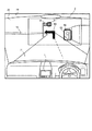
図6は、現在位置と目的地までの距離が所定距離より離れている場合の運転者が視認する前方風景の一例である。図6の例では、ヘッドアップディスプレイ2は、次の右左折地点である道路71と道路72との交差点を右折すべき旨を示す矢印画像80、及び、上記交差点に設けられた信号機91の赤灯火部分と道路71沿いを移動中の歩行者92とをそれぞれ囲んだ強調画像81、82を、コンバイナ5上に表示させている。
FIG. 6 is an example of a front view visually recognized by the driver when the distance between the current position and the destination is greater than a predetermined distance. In the example of FIG. 6, the head-up
この場合、まず、システムコントローラ20は、カメラ3から供給される前方画像Imに基づき、青信号から赤信号に切り替わった直後の信号機91の赤灯火部分と、歩行者92とを対象物Objとして認識する(図5のステップS101、S102参照)。そして、システムコントローラ20は、これらの対象物Objを囲む強調画像81、82と、次に車両Veが進行すべき方向を示す矢印画像80とを、表示すべき案内画像として認識する(ステップS103参照)。そして、システムコントローラ20は、現在位置と目的地までの距離が所定距離より離れていることから、これらの全ての案内画像を、ヘッドアップディスプレイ2に表示させる(ステップS104、S106参照)。
In this case, first, the
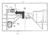
図7は、目的地周辺でのコンバイナ5の表示例を示す。図7では、建物93は、ユーザが設定した目的地の建物を示し、道路74は、建物93に隣接した案内ルート上の道路を示す。
FIG. 7 shows a display example of the
この場合、まず、システムコントローラ20は、図6の場合と同様に、カメラ3から供給される前方画像Imに基づき、青信号から赤信号に切り替わった直後の信号機91aの赤灯火部分と、歩行者92aとを、対象物Objとして認識する(ステップS101、S102参照)。そして、システムコントローラ20は、これらの対象物Objを囲む強調画像と、次に車両Veが進行すべき方向を示す矢印画像とを、表示すべき案内画像として認識する(ステップS103参照)。
In this case, first, similarly to the case of FIG. 6, the
ここで、システムコントローラ20は、目的地が現在位置から所定距離以内に存在することから、図5のステップS105に基づき、表示すべき案内画像について、目的地である建物93との重なり判定を行う(ステップS104参照)。そして、システムコントローラ20は、信号91aの赤信灯火部分を囲む強調画像及び矢印画像については、目的地である建物93と重なると判断して非表示にする(ステップS105参照)。これにより、システムコントローラ20は、目的地である建物93の視認性を好適に確保することができる。一方、システムコントローラ20は、歩行者92aを囲む強調画像82aについては、目的地である建物93と重ならないと判断してヘッドアップディスプレイ2に表示させる。
Here, since the destination exists within a predetermined distance from the current position, the
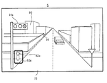
図8は、本実施例とは異なる比較例に係るコンバイナ5の表示例を示す。図8に示す比較例は、案内画像が目的地と重なるか否かに関わらず、全ての案内画像を表示させる例を示す。この場合、システムコントローラ20は、歩行者92aを囲む強調画像82aに加え、信号91aの赤灯火部分を囲む強調画像81a及び進行方向を示す矢印画像80aをヘッドアップディスプレイ2に表示させている。その結果、図8の例では、目的地である建物93と、矢印画像80a及び強調画像81aとが重なってコンバイナ5上で視認され、運転者は、目的地である建物93が見えにくい状態となっている。
FIG. 8 shows a display example of the
以上を勘案し、図7に示す表示例では、システムコントローラ20は、目的地付近では、目的地の視認性を阻害しないように案内画像の表示を制限している。これにより、運転者が初めて訪れる場所であっても、目的地を好適に運転者に視認させることができる。
In consideration of the above, in the display example shown in FIG. 7, the
(3)重なり判定処理
図9は、図5のステップS105で実行する重なり判定処理のフローチャートの一例である。概略的には、図9では、システムコントローラ20は、現在位置と目的地とを通るコンバイナ5上の線分が案内画像の表示位置と重なる場合に、当該案内画像が目的地と重なると判定する。
(3) Overlap determination process FIG. 9 is an example of a flowchart of the overlap determination process executed in step S105 of FIG. Schematically, in FIG. 9, the
まず、システムコントローラ20は、自立測位装置10及びGPS受信機18等により測定した車両Veの現在位置及び進行方向と、地図データの施設情報が示す目的地の位置情報とに基づき、進行方向と目的地の方向とがなす角度「θ」を算出する(ステップS201)。次に、システムコントローラ20は、角度θに基づき、現在位置と目的地とを通るコンバイナ5上の線分「L」を算出する(ステップS202)。そして、システムコントローラ20は、各案内画像を表示するコンバイナ5上の位置(領域)を認識し(ステップS203)、各案内画像の表示位置が線分Lと重なるか否か判定する。そして、システムコントローラ20は、線分Lと重なる案内画像を、前方風景中の目的地と重なる案内画像であると判定する(ステップS204)。そして、システムコントローラ20は、前方風景中の目的地と重なる案内画像を、表示対象から除外する(ステップS205)。
First, the
図10は、図7の例において図9に示す重なり判定処理を適用した例を示す。以下では、図9のフローチャートを適宜参照して図10について説明する。 FIG. 10 shows an example in which the overlap determination process shown in FIG. 9 is applied to the example of FIG. Hereinafter, FIG. 10 will be described with reference to the flowchart of FIG. 9 as appropriate.
まず、システムコントローラ20は、車両Veの現在位置及び進行方向と、目的地の位置情報とに基づき、進行方向と目的地の方向とがなす角度θを算出し(ステップS201参照)、線分Lを認識する(ステップS202参照)。なお、図10の例では、システムコントローラ20は、現在位置に相当するコンバイナ5の下端上の位置から、目的地となる建物93を通りコンバイナ5の上端までを結ぶ線分を、線分Lとして認識している。そして、システムコントローラ20は、表示すべき案内画像である矢印画像80a、強調画像81a、82aの表示領域を、図10に示すように認識する(ステップS203参照)。そして、システムコントローラ20は、各案内画像である矢印画像80a、強調画像81a、82aの表示領域と線分Lとの重なりを判定する。その結果、システムコントローラ20は、矢印画像80a及び強調画像81aの表示領域が線分Lと重なると判断し(ステップS204参照)、矢印画像80a及び強調画像81aを表示対象から除外する(ステップS205参照)。
First, the
このように、システムコントローラ20は、現在位置から目的地まで延びる線分Lを認識し、線分Lと各案内画像との重なり判定を行う。これにより、目的地の視認性を阻害する案内画像を好適に表示対象から除外することができる。
As described above, the
以上説明したように、本実施例に係るナビゲーション装置1のシステムコントローラ20は、車両Veの前方風景に見かけ上で重なるように、案内画像をヘッドアップディスプレイ2に表示させる。そして、システムコントローラ20は、コンバイナ5上の目的地の位置を算出し、算出した目的地の位置が案内画像の表示領域と重なる場合には、当該案内情報を非表示にする。これにより、システムコントローラ20は、目的地の視認性を好適に確保することができる。
As described above, the
[変形例]
次に、上述の実施例に好適な変形例について説明する。以下の変形例は、任意に組み合わせてこれらの実施例に適用してもよい。
[Modification]
Next, a modified example suitable for the above embodiment will be described. The following modifications may be applied to these embodiments in any combination.
(変形例1)
重なり判定処理において、システムコントローラ20は、線分Lと各案内画像の表示領域との重なりを判定する代わりに、コンバイナ5上での目的地の推定領域と各案内画像の表示領域との重なりを判定してもよい。
(Modification 1)
In the overlap determination process, the
図11は、変形例に係る重なり判定処理の概要を示す図である。図11の例では、システムコントローラ20は、実施例と同様に線分Lを認識した後、線分Lを半径とする所定角度「θL」の扇形領域ALを認識する。扇形領域ALは、線分Lを含み、目的地の方向を含むように設定されている。そして、システムコントローラ20は、扇形領域ALと各案内画像との重なりを判定する。その結果、システムコントローラ20は、矢印画像80a及び強調画像81aの表示領域が扇形領域ALと重なると判断し、矢印画像80a及び強調画像81aを表示対象から除外する。
FIG. 11 is a diagram showing an outline of the overlap determination process according to the modification. In the example of FIG. 11, after recognizing the line segment L as in the embodiment, the
図11の例に代えて、システムコントローラ20は、線分Lを所定の太さに設定することで定まる矩形領域を、上述の推定領域として設定してもよい。さらに別の例では、システムコントローラ20は、車両Veの現在位置及び進行方向と目的地の位置情報とに基づき、コンバイナ5上での目的地の中心位置を推定し、推定した目的地の中心位置を中心とする所定の矩形領域又は円領域等の領域を、上述の推定領域として設定してもよい。これらの場合であっても、システムコントローラ20は、設定した推定領域と重なる案内画像を表示対象から除外する。
Instead of the example of FIG. 11, the
(変形例2)
システムコントローラ20は、目的地と重なると判定された案内画像の表示を消去する代わりに、目的地と重なると判定された案内画像の表示位置を、目的地と重ならない位置に移動させてもよい。
(Modification 2)
The
図12は、変形例に係る目的地付近でのコンバイナ5の表示例を示す。図12の例では、システムコントローラ20は、図8の比較例において示した矢印画像80a及び強調画像81a、82aを、表示する案内画像として認識し、かつ、これらの案内画像のうち、矢印画像80a及び強調画像81aが、目的地と重なると判断したものとする。
FIG. 12 shows a display example of the
この場合、システムコントローラ20は、案内画像の種類ごとに、目的地と重なる案内画像を消去すべきか、又は、表示位置を移動させるかを決定する。具体的には、システムコントローラ20は、目的地と重なると判断した案内画像のうち、矢印画像80aについては、表示位置をずらして表示することが可能であると判断し、通常の表示位置よりも右側にずらして矢印画像80aを表示する。この場合、好適には、システムコントローラ20は、変形例1に基づき、扇形領域ALなどの目的地の建物93の推定領域を認識し、当該推定領域と重ならない位置に矢印画像80aの位置をずらすとよい。
In this case, the
一方、システムコントローラ20は、目的地と重なると判断した案内画像のうち、強調画像81aについては、表示位置をずらして表示することができないと判断し、表示対象から除外する。このように、システムコントローラ20は、対象物Objを囲む強調画像については、表示をずらすことなく表示対象から除外する。
On the other hand, the
このように、システムコントローラ20は、例えば、案内画像の種類ごとの表示位置の移動の可否を示すマップ等を予め記憶しておくことで、目的地と重なる案内画像の種類ごとに、当該案内画像を消去すべきか、又は、表示位置を移動させるかを決定する。これによっても、システムコントローラ20は、目的地と重なる案内画像の表示を好適に制限し、目的地の視認性を確保することができる。
In this way, the
また、システムコントローラ20は、目的地と重なると判定された案内画像の表示を消去する代わりに、当該案内画像の輝度を低くしたり、透過度を上げたりすることにより、当該案内画像の表示を制限してもよい。これによっても、案内画像と重なる目的地の視認性を好適に確保することができる。
Further, instead of deleting the display of the guide image determined to overlap the destination, the
(変形例3)
システムコントローラ20は、カメラ3から取得される前方画像Imから目的地にある施設(建物)の表示領域を抽出することで、目的地にある施設のコンバイナ5上での表示領域を認識し、当該表示領域と重なる案内画像の表示を制限してもよい。
(Modification 3)
The
例えば、システムコントローラ20は、目的地に設定された施設の施設情報に、形状、色、高さなどの当該施設の見た目上の特徴を表す情報が含まれていた場合には、目的地に近付いた場合に、当該情報を参照することで、前方画像Imから目的地となる施設を検出する処理を行う。そして、システムコントローラ20は、前方画像Imから目的地となる施設を検出した場合、検出した領域に対応するコンバイナ5上の領域を、目的地にある施設の表示領域であると推定する。そして、システムコントローラ20は、目的地にある施設の推定した表示領域と重なる案内画像の表示を制限する。
For example, the
(変形例4)
視認性を確保する対象を目的地に設定するのに代えて、又はこれに加えて、システムコントローラ20は、経由地や特定の目印(ランドマーク)等の任意の案内対象となる施設又は地点(「案内地」とも呼ぶ。)を、実施例の目的地と同様に、案内画像との重なりを抑制する対象とみなしてもよい。この場合、案内地は、ユーザが任意に設定した施設であってもよく、案内ルート上の右左折地点で目印となる施設であってもよい。そして、この場合であっても、システムコントローラ20は、設定した案内地と現在位置との距離が所定距離以内となった場合に、重なり判定処理を行い、当該案内地と重なる案内画像の表示を制限する。
(Modification 4)
Instead of or in addition to setting a target for ensuring visibility as a destination, the
(変形例5)
システムコントローラ20は、目的地と重なった場合であっても、表示を制限しない案内画像の種類を定めてもよい。例えば、システムコントローラ20は、道路上の歩行者などの特定種類の対象物Objについては、当該対象物Objを囲む強調画像を表示して注意喚起を行う必要性が高いと判断し、目的地と重なる場合であっても、表示を制限しない。これにより、運転上の安全を好適に確保することができる。
(Modification 5)
The
(変形例6)
ナビゲーション装置1のシステムコントローラ20が図5に示すフローチャートの処理を実行する代わりに、ヘッドアップディスプレイ2の制御部55が図5に示すフローチャートの処理を実行してもよい。
(Modification 6)
Instead of the
この場合、ナビゲーション装置1は、ステップS101乃至ステップS106の実行に必要な情報である前方画像Im、車両Veの現在位置の情報、進行方向の情報、施設情報等を、ヘッドアップディスプレイ2に送信する。そして、制御部55は、ナビゲーション装置1から送信される情報に基づき、ステップS101乃至ステップS106を実行することで案内画像の表示制御を行う。
In this case, the
この変形例では、制御部55は、本発明における「表示制御部」、「算出部」、「現在位置取得部」、「進行方向取得部」、「案内地情報取得部」及びプログラムを実行するコンピュータとして機能する。
In this modification, the
(変形例7)
図3では、ヘッドアップディスプレイ2は、コンバイナ5を有し、コンバイナ5で反射させた光源ユニット3の出射光に基づき運転者に虚像Ivを視認させていた。しかし、本発明が適用可能な構成はこれに限定されない。これに代えて、ヘッドアップディスプレイ2は、コンバイナ5を有さず、フロントガラス25で反射させた光源ユニット3の出射光に基づき運転者に虚像Ivを視認させてもよい。この場合、フロントガラス25は、本発明における「表示部」の一例である。
(Modification 7)
In FIG. 3, the head-up
また、光源ユニット3の位置は、天井部27に設置される場合に限定されない。これに代えて、光源ユニット3は、ダッシュボード上に設置されたり、ダッシュボードの内部に設置されたりしてもよい。ダッシュボード上に設置される場合、ダッシュボードには、コンバイナ5を設けるか、又はフロントガラス25に光源ユニット3から直接光を反射させ運転者に虚像Ivを認識させる。ダッシュボード内に設置される場合、ダッシュボードには、コンバイナ5又はフロントガラス25に光を通過させるための開口部が設けられる。
Further, the position of the
(変形例8)
表示システム100は、ヘッドアップディスプレイ2により前方風景に重畳させて案内画像を表示させるのに代えて、カメラ3により撮影した前方画像Imに案内画像を重畳させてナビゲーション装置1により表示させてもよい。
(Modification 8)
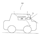
The
図13は、変形例に係る表示システム100Aの構成例を示す。図13の例では、ナビゲーション装置1のシステムコントローラ20は、カメラ3から取得した前方画像Imに、案内画像を重ねてディスプレイ44に表示させる。このように、カメラ3が撮影した前方画像Imに重畳させて案内画像を表示した場合であっても、システムコントローラ20は、前方画像Im中の目的地の表示領域と重なる案内画像の表示を制限する。これにより、システムコントローラ20は、ディスプレイ44上で表示される前方画像Im中での目的地の視認性を好適に確保することができる。
FIG. 13 shows a configuration example of a
また、ナビゲーション装置1が携帯端末の場合、ナビゲーション装置1は、歩行者を案内するものであってもよい。この場合、ナビゲーション装置1はカメラ3を内蔵し、カメラ3が撮影した前方画像に重畳させて案内画像を表示する。
Moreover, when the
この変形例では、ディスプレイ44は、本発明における「表示部」として機能する。 In this modification, the display 44 functions as a “display unit” in the present invention.
(変形例9)
表示制限の対象となる案内画像は、車両Veの次の右左折地点での進行方向を示す矢印画像及び対象物Objを囲む強調画像に限らず、車両Veの速度を示す画像、次の右左折地点までの距離を示す画像などの種々の画像であってもよい。
(Modification 9)
The guide image subject to display restriction is not limited to the arrow image indicating the traveling direction at the next right / left turn point of the vehicle Ve and the emphasized image surrounding the object Obj, but the image indicating the speed of the vehicle Ve, the next right / left turn Various images such as an image showing the distance to the point may be used.
1 ナビゲーション装置
2 ヘッドアップディスプレイ
3 光源ユニット
4 本体部
5 コンバイナ
25 フロントガラス
DESCRIPTION OF
Claims (10)
前記表示部上の前記移動体の移動に関しての案内をする地点である案内地の位置を算出する算出部と、
を備え、
前記表示制御部は、前記算出部が算出した前記表示部上の前記案内地の位置が前記第一領域と重なる場合には、前記案内情報の前記第一領域への表示を制限することを特徴とする表示制御装置。 A display control unit that displays guidance information in a first area of the display unit so as to be superimposed on a landscape image obtained by capturing a landscape in front of a moving object or to overlap the landscape in appearance.
A calculation unit that calculates a position of a guidance place that is a point for guidance on movement of the moving object on the display unit;
With
The display control unit restricts display of the guidance information in the first region when the position of the guidance location on the display unit calculated by the calculation unit overlaps the first region. A display control device.
前記算出部が算出した前記表示部上の前記案内地の位置が前記第一領域と重なる場合には、前記案内情報のうち、所定の種類の案内情報を前記第二領域へ表示することを特徴とする請求項2に記載の表示制御装置。 The display control unit displays a plurality of types of the guidance information, and
When the position of the guide location on the display unit calculated by the calculation unit overlaps the first region, a predetermined type of guide information is displayed in the second region among the guide information. The display control device according to claim 2.
前記移動体の進行方向に関する情報を取得する進行方向取得部と、
前記移動体の案内地に関する案内地情報を取得する案内地情報取得部と、をさらに備え、
前記算出部は、前記現在位置と前記進行方向と前記案内地情報とに基づき、前記表示部上の前記案内地の位置を算出することを特徴とする請求項1乃至3のいずれか一項に記載の表示制御装置。 A current position acquisition unit for acquiring a current position of the moving body;
A traveling direction acquisition unit that acquires information on the traveling direction of the moving body;
A guide location information acquisition unit that acquires guide location information related to the guide location of the mobile body,
The said calculation part calculates the position of the said guidance place on the said display part based on the said present position, the said advancing direction, and the said guidance place information, The Claim 1 thru | or 3 characterized by the above-mentioned. The display control apparatus described.
移動体の前方の風景を撮影した風景画像に重畳して、または前記風景に見かけ上で重なるように、案内情報を表示部の第一領域に表示させる表示制御工程と、
前記表示部上の前記移動体の移動に関しての案内をする地点である案内地の位置を算出する算出工程と、
を備え、
前記表示制御工程は、前記算出工程が算出した前記表示部上の前記案内地の位置が前記第一領域と重なる場合には、前記案内情報の前記第一領域への表示を制限することを特徴とする制御方法。 A control method executed by a display control device,
A display control step of displaying guidance information on the first area of the display unit so as to be superimposed on a landscape image obtained by capturing a landscape in front of a moving object or to be superimposed on the landscape in appearance.
A calculation step of calculating a position of a guide point that is a point for guiding the movement of the moving body on the display unit;
With
The display control step restricts the display of the guidance information in the first region when the position of the guidance location on the display unit calculated by the calculation step overlaps the first region. Control method.
移動体の前方の風景を撮影した風景画像に重畳して、または前記風景に見かけ上で重なるように、案内情報を表示部の第一領域に表示させる表示制御部と、
前記表示部上の前記移動体の移動に関しての案内をする地点である案内地の位置を算出する算出部
として前記コンピュータを機能させ、
前記表示制御部は、前記算出部が算出した前記表示部上の前記案内地の位置が前記第一領域と重なる場合には、前記案内情報の前記第一領域への表示を制限することを特徴とするプログラム。 A program executed by a computer,
A display control unit that displays guidance information in a first area of the display unit so as to be superimposed on a landscape image obtained by capturing a landscape in front of a moving object or to overlap the landscape in appearance.
Causing the computer to function as a calculation unit that calculates a position of a guide point that is a point to guide the movement of the mobile object on the display unit;
The display control unit restricts display of the guidance information in the first region when the position of the guidance location on the display unit calculated by the calculation unit overlaps the first region. Program.
Priority Applications (1)
| Application Number | Priority Date | Filing Date | Title |
|---|---|---|---|
| JP2014027285A JP2015152467A (en) | 2014-02-17 | 2014-02-17 | display control device, control method, program, and storage medium |
Applications Claiming Priority (1)
| Application Number | Priority Date | Filing Date | Title |
|---|---|---|---|
| JP2014027285A JP2015152467A (en) | 2014-02-17 | 2014-02-17 | display control device, control method, program, and storage medium |
Publications (2)
| Publication Number | Publication Date |
|---|---|
| JP2015152467A true JP2015152467A (en) | 2015-08-24 |
| JP2015152467A5 JP2015152467A5 (en) | 2016-11-10 |
Family
ID=53894877
Family Applications (1)
| Application Number | Title | Priority Date | Filing Date |
|---|---|---|---|
| JP2014027285A Pending JP2015152467A (en) | 2014-02-17 | 2014-02-17 | display control device, control method, program, and storage medium |
Country Status (1)
| Country | Link |
|---|---|
| JP (1) | JP2015152467A (en) |
Cited By (4)
| Publication number | Priority date | Publication date | Assignee | Title |
|---|---|---|---|---|
| WO2017163385A1 (en) * | 2016-03-24 | 2017-09-28 | 三菱電機株式会社 | Support image display device, support image display method, and support image display program |
| WO2018180122A1 (en) * | 2017-03-30 | 2018-10-04 | ソニー株式会社 | Operation assistance device and operation assistance method |
| JP2019095214A (en) * | 2017-11-17 | 2019-06-20 | アイシン・エィ・ダブリュ株式会社 | Superimposed image display device and computer program |
| WO2020110580A1 (en) * | 2018-11-30 | 2020-06-04 | 株式会社小糸製作所 | Head-up display, vehicle display system, and vehicle display method |
Citations (5)
| Publication number | Priority date | Publication date | Assignee | Title |
|---|---|---|---|---|
| JP2004333155A (en) * | 2003-04-30 | 2004-11-25 | Sony Corp | Information presenting device, information presenting method, and computer program |
| JP2005207785A (en) * | 2004-01-20 | 2005-08-04 | Mazda Motor Corp | Image display apparatus, method, and program for vehicle |
| JP2006284458A (en) * | 2005-04-01 | 2006-10-19 | Denso Corp | System for displaying drive support information |
| JPWO2009084134A1 (en) * | 2007-12-28 | 2011-05-12 | 三菱電機株式会社 | Navigation device |
| WO2013111302A1 (en) * | 2012-01-26 | 2013-08-01 | パイオニア株式会社 | Display device, control method, program, and storage medium |
-
2014
- 2014-02-17 JP JP2014027285A patent/JP2015152467A/en active Pending
Patent Citations (5)
| Publication number | Priority date | Publication date | Assignee | Title |
|---|---|---|---|---|
| JP2004333155A (en) * | 2003-04-30 | 2004-11-25 | Sony Corp | Information presenting device, information presenting method, and computer program |
| JP2005207785A (en) * | 2004-01-20 | 2005-08-04 | Mazda Motor Corp | Image display apparatus, method, and program for vehicle |
| JP2006284458A (en) * | 2005-04-01 | 2006-10-19 | Denso Corp | System for displaying drive support information |
| JPWO2009084134A1 (en) * | 2007-12-28 | 2011-05-12 | 三菱電機株式会社 | Navigation device |
| WO2013111302A1 (en) * | 2012-01-26 | 2013-08-01 | パイオニア株式会社 | Display device, control method, program, and storage medium |
Cited By (9)
| Publication number | Priority date | Publication date | Assignee | Title |
|---|---|---|---|---|
| WO2017163385A1 (en) * | 2016-03-24 | 2017-09-28 | 三菱電機株式会社 | Support image display device, support image display method, and support image display program |
| JPWO2017163385A1 (en) * | 2016-03-24 | 2018-04-12 | 三菱電機株式会社 | Support image display device, support image display method, and support image display program |
| CN108885845A (en) * | 2016-03-24 | 2018-11-23 | 三菱电机株式会社 | Assistant images display device, assistant images display methods and assistant images show program |
| CN108885845B (en) * | 2016-03-24 | 2021-02-26 | 三菱电机株式会社 | Auxiliary image display device, auxiliary image display method, and computer-readable recording medium |
| WO2018180122A1 (en) * | 2017-03-30 | 2018-10-04 | ソニー株式会社 | Operation assistance device and operation assistance method |
| JP2019095214A (en) * | 2017-11-17 | 2019-06-20 | アイシン・エィ・ダブリュ株式会社 | Superimposed image display device and computer program |
| WO2020110580A1 (en) * | 2018-11-30 | 2020-06-04 | 株式会社小糸製作所 | Head-up display, vehicle display system, and vehicle display method |
| JPWO2020110580A1 (en) * | 2018-11-30 | 2021-11-11 | 株式会社小糸製作所 | Head-up display, vehicle display system, and vehicle display method |
| JP7254832B2 (en) | 2018-11-30 | 2023-04-10 | 株式会社小糸製作所 | HEAD-UP DISPLAY, VEHICLE DISPLAY SYSTEM, AND VEHICLE DISPLAY METHOD |
Similar Documents
| Publication | Publication Date | Title |
|---|---|---|
| JP4975889B1 (en) | Head-up display, control method, and display device | |
| WO2014097404A1 (en) | Head-up display, control method, program and storage medium | |
| JP5795386B2 (en) | Display device and control method | |
| JP2015128956A (en) | Head-up display, control method, program and storage medium | |
| JP2015172548A (en) | Display control device, control method, program, and recording medium | |
| WO2015045112A1 (en) | Driving-assistance apparatus, control method, program, and storage medium | |
| JP5197881B1 (en) | Head-up display, control method, and display device | |
| JP5735658B2 (en) | Display device and display method | |
| JP2016193723A (en) | Display device, program, and storage medium | |
| JP2018128466A (en) | Navigation device, head-up display, control method, program, and storage medium | |
| JP2015152467A (en) | display control device, control method, program, and storage medium | |
| JP2015105903A (en) | Navigation device, head-up display, control method, program, and storage medium | |
| WO2015114807A1 (en) | Virtual image display, control method, program, and storage medium | |
| JP2015141155A (en) | virtual image display device, control method, program, and storage medium | |
| WO2014076841A1 (en) | Display apparatus, control method, program, and recording medium | |
| JP5702476B2 (en) | Display device, control method, program, storage medium | |
| WO2014097403A1 (en) | Display device, control method, program, and storage medium | |
| JP6401925B2 (en) | Virtual image display device, control method, program, and storage medium | |
| JP2016176962A (en) | Display device, head-up display, control method, program, and storage medium | |
| WO2014109030A1 (en) | Virtual image-displaying device, control method, program and memory medium | |
| WO2013046426A1 (en) | Head-up display, image display method, image display program, and display device | |
| JP2020064076A (en) | Display device, head-up display, control method, program, and storage medium | |
| JP2018158725A (en) | Head-up display, control method, program and storage medium | |
| WO2013046423A1 (en) | Head-up display, control method, and display device | |
| WO2013046425A1 (en) | Head-up display, control method, and display device |
Legal Events
| Date | Code | Title | Description |
|---|---|---|---|
| A521 | Request for written amendment filed |
Free format text: JAPANESE INTERMEDIATE CODE: A523 Effective date: 20160926 |
|
| A621 | Written request for application examination |
Free format text: JAPANESE INTERMEDIATE CODE: A621 Effective date: 20170111 |
|
| A977 | Report on retrieval |
Free format text: JAPANESE INTERMEDIATE CODE: A971007 Effective date: 20171019 |
|
| A131 | Notification of reasons for refusal |
Free format text: JAPANESE INTERMEDIATE CODE: A131 Effective date: 20171024 |
|
| A521 | Request for written amendment filed |
Free format text: JAPANESE INTERMEDIATE CODE: A523 Effective date: 20171130 |
|
| A02 | Decision of refusal |
Free format text: JAPANESE INTERMEDIATE CODE: A02 Effective date: 20171212 |