JP2014241514A - Communication device, communication system, communication method, and program - Google Patents
Communication device, communication system, communication method, and program Download PDFInfo
- Publication number
- JP2014241514A JP2014241514A JP2013123175A JP2013123175A JP2014241514A JP 2014241514 A JP2014241514 A JP 2014241514A JP 2013123175 A JP2013123175 A JP 2013123175A JP 2013123175 A JP2013123175 A JP 2013123175A JP 2014241514 A JP2014241514 A JP 2014241514A
- Authority
- JP
- Japan
- Prior art keywords
- communication
- signal
- received
- wired
- unit
- Prior art date
- Legal status (The legal status is an assumption and is not a legal conclusion. Google has not performed a legal analysis and makes no representation as to the accuracy of the status listed.)
- Pending
Links
Images


Classifications
-
- H—ELECTRICITY
- H04—ELECTRIC COMMUNICATION TECHNIQUE
- H04B—TRANSMISSION
- H04B3/00—Line transmission systems
- H04B3/02—Details
- H04B3/46—Monitoring; Testing
-
- H—ELECTRICITY
- H04—ELECTRIC COMMUNICATION TECHNIQUE
- H04B—TRANSMISSION
- H04B7/00—Radio transmission systems, i.e. using radiation field
- H04B7/02—Diversity systems; Multi-antenna system, i.e. transmission or reception using multiple antennas
- H04B7/022—Site diversity; Macro-diversity
-
- H—ELECTRICITY
- H04—ELECTRIC COMMUNICATION TECHNIQUE
- H04B—TRANSMISSION
- H04B7/00—Radio transmission systems, i.e. using radiation field
- H04B7/02—Diversity systems; Multi-antenna system, i.e. transmission or reception using multiple antennas
- H04B7/04—Diversity systems; Multi-antenna system, i.e. transmission or reception using multiple antennas using two or more spaced independent antennas
- H04B7/08—Diversity systems; Multi-antenna system, i.e. transmission or reception using multiple antennas using two or more spaced independent antennas at the receiving station
- H04B7/0802—Diversity systems; Multi-antenna system, i.e. transmission or reception using multiple antennas using two or more spaced independent antennas at the receiving station using antenna selection
- H04B7/0805—Diversity systems; Multi-antenna system, i.e. transmission or reception using multiple antennas using two or more spaced independent antennas at the receiving station using antenna selection with single receiver and antenna switching
- H04B7/0814—Diversity systems; Multi-antenna system, i.e. transmission or reception using multiple antennas using two or more spaced independent antennas at the receiving station using antenna selection with single receiver and antenna switching based on current reception conditions, e.g. switching to different antenna when signal level is below threshold
-
- H—ELECTRICITY
- H04—ELECTRIC COMMUNICATION TECHNIQUE
- H04B—TRANSMISSION
- H04B7/00—Radio transmission systems, i.e. using radiation field
- H04B7/02—Diversity systems; Multi-antenna system, i.e. transmission or reception using multiple antennas
- H04B7/04—Diversity systems; Multi-antenna system, i.e. transmission or reception using multiple antennas using two or more spaced independent antennas
- H04B7/08—Diversity systems; Multi-antenna system, i.e. transmission or reception using multiple antennas using two or more spaced independent antennas at the receiving station
- H04B7/0802—Diversity systems; Multi-antenna system, i.e. transmission or reception using multiple antennas using two or more spaced independent antennas at the receiving station using antenna selection
- H04B7/0817—Diversity systems; Multi-antenna system, i.e. transmission or reception using multiple antennas using two or more spaced independent antennas at the receiving station using antenna selection with multiple receivers and antenna path selection
- H04B7/082—Diversity systems; Multi-antenna system, i.e. transmission or reception using multiple antennas using two or more spaced independent antennas at the receiving station using antenna selection with multiple receivers and antenna path selection selecting best antenna path
-
- H—ELECTRICITY
- H04—ELECTRIC COMMUNICATION TECHNIQUE
- H04B—TRANSMISSION
- H04B7/00—Radio transmission systems, i.e. using radiation field
- H04B7/02—Diversity systems; Multi-antenna system, i.e. transmission or reception using multiple antennas
- H04B7/04—Diversity systems; Multi-antenna system, i.e. transmission or reception using multiple antennas using two or more spaced independent antennas
- H04B7/08—Diversity systems; Multi-antenna system, i.e. transmission or reception using multiple antennas using two or more spaced independent antennas at the receiving station
- H04B7/0868—Hybrid systems, i.e. switching and combining
- H04B7/0871—Hybrid systems, i.e. switching and combining using different reception schemes, at least one of them being a diversity reception scheme
Landscapes
- Engineering & Computer Science (AREA)
- Computer Networks & Wireless Communication (AREA)
- Signal Processing (AREA)
- Radio Transmission System (AREA)
Abstract
Description
本発明はダイバーシチ受信技術に関する。 The present invention relates to diversity reception technology.
無線通信では、様々な伝搬経路を介した複数の素波が異なるタイミングで受信装置に到来するマルチパス環境が形成され、場所によっては、受信波形が歪むことで伝送誤りが生じる場合があることが知られている。このようなマルチパス環境において、通信品質を改善するための技術として、空間ダイバーシチがよく知られている。空間ダイバーシチでは、アンテナの位置によって通信品質が大きく変動することを利用し、複数のアンテナを空間的に離して配置して同時に通信を行う。これにより、例えば、複数のアンテナで受信された無線信号の通信品質がそれぞれ異なることとなるため、少なくともいずれかのアンテナにおいて十分な受信品質を得ることができる確率を向上させることができる。なお、受信装置は、例えば、複数のアンテナにおける受信信号を選択合成もしくは最大比合成して復調することにより、又は、複数の受信信号に基づく最尤推定を行うことにより、その複数の受信信号から受信データを得ることができる。 In wireless communication, a multipath environment is formed in which multiple elementary waves through various propagation paths arrive at the receiving device at different timings. Depending on the location, the received waveform may be distorted and transmission errors may occur. Are known. In such a multipath environment, space diversity is well known as a technique for improving communication quality. Spatial diversity utilizes the fact that the communication quality varies greatly depending on the position of the antenna, and a plurality of antennas are spatially separated and communicated simultaneously. Thereby, for example, since the communication qualities of radio signals received by a plurality of antennas are different from each other, it is possible to improve the probability that sufficient reception quality can be obtained by at least one of the antennas. Note that the receiving device can perform, for example, selective combining or maximum ratio combining and demodulating received signals from a plurality of antennas, or performing maximum likelihood estimation based on the plurality of received signals from the received signals. Received data can be obtained.
複数のアンテナ(ダイバーシチブランチ)を空間的に広く分布させることにより、このようなダイバーシチの効果をさらに高めることができると考えられる。そして、この場合、広範囲に分布された複数のアンテナと選択合成等の受信処理を行う制御機能部とが空間的に離れることとなるため、制御機能部と複数のアンテナのそれぞれとが、ケーブル等により有線接続される。そして、複数のアンテナで受信した信号は有線伝送路を介して制御機能部に伝送され、制御機能部は、受信した信号に受信処理を施すこととなる。 It is considered that the effect of such diversity can be further enhanced by spatially distributing a plurality of antennas (diversity branches). In this case, since a plurality of antennas distributed over a wide area and a control function unit that performs reception processing such as selective combining are spatially separated, the control function unit and each of the plurality of antennas are connected with cables, etc. Wired connection. The signals received by the plurality of antennas are transmitted to the control function unit via the wired transmission path, and the control function unit performs reception processing on the received signal.
しかしながら、制御機能部と複数のアンテナとが有線接続される場合、制御機能部は、少なくともアンテナの本数分の有線通信用のインタフェースを有していなければならない。ここで、無線区間と有線区間を併せた通信システム全体での通信速度に影響を与えないために、この有線通信用のインタフェースには、無線区間以上に高速な通信性能が求められる。例えば、非圧縮HD動画を送信器から無線伝送して、サイトダイバーシチ無線受信局で受信する無線通信システムにおいては、制御機能部は、1Gbpsを超える有線通信用のインタフェースを複数有しなければならない。このように、制御機能部が多数の高速な有線通信用インタフェースを有する構成とすることは、ハードウェアの複雑性やコストの観点から容易ではない。また、制御機能部が有する有線通信用インタフェースの数を超えてアンテナ数を増やすことができないため、システムの拡張性や柔軟性が制限される。 However, when the control function unit and a plurality of antennas are connected by wire, the control function unit must have at least as many interfaces for wired communication as the number of antennas. Here, in order not to affect the communication speed of the entire communication system including the wireless section and the wired section, this wired communication interface is required to have a higher communication performance than the wireless section. For example, in a wireless communication system in which an uncompressed HD moving image is wirelessly transmitted from a transmitter and received by a site diversity wireless reception station, the control function unit must have a plurality of wired communication interfaces exceeding 1 Gbps. Thus, it is not easy from the viewpoint of hardware complexity and cost to have a configuration in which the control function unit has a number of high-speed wired communication interfaces. In addition, since the number of antennas cannot be increased beyond the number of wired communication interfaces included in the control function unit, the expandability and flexibility of the system are limited.
また、あるダイバーシチブランチが制御機能部から遠く離れた位置に設置される場合に、長い通信ケーブルを敷設することが要求される。そして、コストまたは入手性の観点から、長い通信ケーブルを利用することも必ずしも容易ではない。さらに、多数の通信ケーブルが、制御機能部の近傍に集中することとなるため、ケーブルの配回しが複雑になりうるという課題もある。 Further, when a diversity branch is installed at a position far from the control function unit, it is required to install a long communication cable. From the viewpoint of cost or availability, it is not always easy to use a long communication cable. Furthermore, since a large number of communication cables are concentrated in the vicinity of the control function unit, there is a problem that the cable distribution can be complicated.
これに対して、複数のダイバーシチブランチ(アンテナを有する通信ユニット)を通信ケーブルで直列に接続する、デイジーチェーン型のダイバーシチ受信局が検討されている(特許文献1及び特許文献2参照)。すなわち、アンテナを有する通信ユニットのそれぞれが直列に有線接続され、各通信ユニットは、例えば、アンテナで受信した信号とデイジーチェーンの下位ユニットのアンテナで受信された信号とを合成して上位ユニットへ転送する。このように、アンテナをそれぞれが有する通信ユニットをデイジーチェーン接続することにより、制御機能部は、アンテナ数分の有線通信インタフェースを有さなくてもよくなる。なお、ここでは、1つの通信ユニットから見て、デイジーチェーンの制御機能部に近い方の通信ユニットを上位ユニットと呼び、制御機能部に遠い方の通信ユニットを下位ユニットと呼ぶ。同様に、1つの通信ユニットから見て、制御機能部の方向を上位方向、反対の方向を下位方向と呼ぶ。 On the other hand, a daisy chain type diversity receiving station in which a plurality of diversity branches (communication units having an antenna) are connected in series with a communication cable has been studied (see Patent Document 1 and Patent Document 2). That is, each communication unit having an antenna is connected in series with each other, and each communication unit, for example, synthesizes the signal received by the antenna and the signal received by the antenna of the lower unit of the daisy chain and transfers it to the upper unit. To do. In this way, by connecting the communication units each having an antenna in a daisy chain, the control function unit does not have to have wired communication interfaces corresponding to the number of antennas. Here, as viewed from one communication unit, a communication unit closer to the control function unit of the daisy chain is referred to as an upper unit, and a communication unit farther from the control function unit is referred to as a lower unit. Similarly, when viewed from one communication unit, the direction of the control function unit is referred to as an upper direction, and the opposite direction is referred to as a lower direction.
そして、特許文献1には、各通信ユニットが、受信した無線信号とその信頼係数、及びデイジーチェーンの下位ユニットから受信した結合信号とその結合信頼係数の4つの入力から、新たな結合信号と結合信頼係数を生成して出力する技術が記載されている。そして、これをデイジーチェーン接続された通信ユニットの全てが実行することで、制御機能部は、最上位の通信ユニットから、重み付けされた合成受信信号を得ることができる。 In Patent Document 1, each communication unit combines a new combined signal from four inputs of a received radio signal and its reliability coefficient, and a combined signal received from a lower unit of the daisy chain and its combined reliability coefficient. A technique for generating and outputting a confidence coefficient is described. Then, by executing all of the daisy chain connected communication units, the control function unit can obtain a weighted combined reception signal from the highest-level communication unit.
また、特許文献2には、各通信ユニットが、自らが受信した無線信号の受信レベルと、下位ユニットから入力された、下位ユニットが受信した無線信号の受信レベルとを比較して、上位ユニットに送信する信号を選択する技術が記載されている。すなわち、特許文献2においては、各通信ユニットは、自らが受信した無線信号の受信レベルが下位ユニットで受信された無線信号の受信レベルより高い場合には、自らが受信した無線信号と、その受信レベルを上位ユニットに伝送する。また、各通信ユニットは、自らが受信した無線信号の受信レベルが下位ユニットで受信された無線信号の受信レベル以下の場合には、下位ユニットから入力された、下位ユニットにおいて受信された信号と受信レベルとを上位ユニットに中継伝送する。これを、最下位の通信ユニットから最上位の通信ユニットに向かって繰り返すことで、制御機能部は、最上位の通信ユニットから、最大の受信レベルを有する通信ユニットが受信した信号を得ることができる。 Further, in Patent Document 2, each communication unit compares the reception level of the radio signal received by itself with the reception level of the radio signal received from the lower unit and received by the lower unit. A technique for selecting a signal to be transmitted is described. That is, in Patent Literature 2, each communication unit receives a radio signal received by itself and its reception when the reception level of the radio signal received by itself is higher than the reception level of the radio signal received by the lower unit. Transmit the level to the upper unit. Each communication unit receives a signal received from the lower unit and received from the lower unit when the reception level of the radio signal received by the communication unit is equal to or lower than the reception level of the radio signal received by the lower unit. The level is relayed to the upper unit. By repeating this from the lowest communication unit toward the highest communication unit, the control function unit can obtain the signal received by the communication unit having the highest reception level from the highest communication unit. .
しかしながら、特許文献1に記載の技術を有意に活用するためには、通信ユニット間で伝送される結合信号は軟判定値でなければならず、有線通信インタフェースが高い通信性能を有する必要があるという課題があった。例えば、1Byteで量子化された軟判定値を結合信号として伝送するためには、無線区間の8倍以上の通信速度が有線インタフェースに必要とされる。また、特許文献2に記載の技術では、各通信ユニットは、無線信号の受信レベルを上位ユニットに伝達しなければならず、通信ユニットの装置規模の増大及び伝送すべき情報量の増大を招くという課題があった。 However, in order to use the technique described in Patent Document 1 significantly, the combined signal transmitted between the communication units must be a soft decision value, and the wired communication interface needs to have high communication performance. There was a problem. For example, in order to transmit a soft decision value quantized with 1 byte as a combined signal, a communication speed of 8 times or more of the wireless section is required for the wired interface. In the technique described in Patent Document 2, each communication unit must transmit the reception level of the radio signal to the upper unit, which increases the device size of the communication unit and increases the amount of information to be transmitted. There was a problem.
本発明は上記課題に鑑みなされたものであり、より簡易な装置構成で空間ダイバーシチ効果を得られるようにすることを目的とする。 The present invention has been made in view of the above problems, and an object of the present invention is to obtain a space diversity effect with a simpler apparatus configuration.
上記目的を達成するため、本発明による通信装置は、アンテナをそれぞれ有する複数の通信装置が直列に有線接続され、少なくとも1つの前記通信装置は、前記アンテナで受信した無線信号と有線で接続された第1の通信装置から受信した有線信号とのいずれかを選択して、有線で接続されると共に前記第1の通信装置とは異なる、第2の通信装置または制御装置へ送信することにより、前記制御装置が前記複数の通信装置のいずれかで受信された無線信号を受信する通信システムにおける前記通信装置であって、前記受信した無線信号の受信品質が所定の品質を満たすかを判定する判定手段と、前記受信品質が所定の品質を満たす場合は前記受信した無線信号を前記第2の通信装置または前記制御装置へ送信し、前記受信品質が所定の品質を満たさない場合は前記有線信号を前記第2の通信装置または前記制御装置へ送信する送信手段と、を有する。 In order to achieve the above object, in a communication device according to the present invention, a plurality of communication devices each having an antenna are wired in series, and at least one of the communication devices is wired with a wireless signal received by the antenna. By selecting one of the wired signals received from the first communication device and transmitting to a second communication device or control device that is connected by wire and is different from the first communication device, Determining means for determining whether or not the reception quality of the received radio signal satisfies a predetermined quality in the communication system in a communication system in which a control device receives a radio signal received by any of the plurality of communication devices When the reception quality satisfies a predetermined quality, the received radio signal is transmitted to the second communication device or the control device, and the reception quality is a predetermined quality. If not satisfied and a transmission means for transmitting the wireline signal to the second communication device or the control device.
本発明によれば、より簡易な装置構成で空間ダイバーシチ効果を得ることができる。 According to the present invention, a space diversity effect can be obtained with a simpler apparatus configuration.
以下、添付図面を参照して本発明の実施の形態を詳細に説明する。 Hereinafter, embodiments of the present invention will be described in detail with reference to the accompanying drawings.
<<実施形態1>>
(ダイバーシチ受信装置の構成)
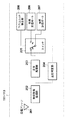
図1は、本実施形態におけるダイバーシチ受信装置100の構成例を示すブロック図である。ダイバーシチ受信装置100は、複数のアンテナ(ダイバーシチブランチ)と、その複数のアンテナのそれぞれに対応する複数の通信ユニット(第1〜第3の通信ユニット111〜113)と、制御部101とを有する。第1〜第3の通信ユニット111〜113は、制御部101に、デイジーチェーン接続される。より具体的には、第1の通信ユニット111は、第1の通信ケーブル121を介して、制御部101に有線接続され、第2の通信ユニット112は、第2の通信ケーブル122を介して、第1の通信ユニット111に有線接続される。同様に、第3の通信ユニット113は、第3の通信ケーブル123を介して、第2の通信ユニット112に有線接続される。このように、ダイバーシチ受信装置100内においては、アンテナをそれぞれ伴う複数の通信ユニットが直列に有線接続され、そのうちの1つの通信ユニットが制御部101に接続される通信システムが構築される。
<< Embodiment 1 >>
(Configuration of diversity receiver)
FIG. 1 is a block diagram illustrating a configuration example of the
なお、ここでは、ある通信ユニットから見て、デイジーチェーンの制御部101側の方向を上位方向と呼び、反対方向を下位方向と呼ぶ。すなわち、図1においては、第1の通信ユニット111はデイジーチェーンの最上位の通信ユニットであり、第3の通信ユニット113は最下位の通信ユニットである。なお、最上位の通信ユニットである第1の通信ユニットは、制御部101に有線接続される。また、第2の通信ユニット112から見て、第1の通信ユニット111は隣接する上位の通信ユニットであり、第3の通信ユニット113は隣接する下位の通信ユニットである。
Here, as viewed from a certain communication unit, the direction on the
(通信ユニットの構成)
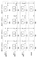
図2は、本実施形態に係る第1〜第3の通信ユニット111〜113の構成例を示すブロック図である。各通信ユニットは、例えば、受信アンテナ201、無線受信処理部202、送信処理部203、品質判定部204、スイッチ205、有線受信ポート206、有線送信ポート207、及び下位ユニット検出部208を有する。
(Configuration of communication unit)
FIG. 2 is a block diagram illustrating a configuration example of the first to
受信アンテナ201は無線信号を受信し、受信した無線信号を無線受信処理部202に出力する。ここで、無線信号のフレーム構成例を図3に示す。図3において、無線フレーム300は、プリアンブル301と第1〜第4のデータブロック311〜314とを含む。プリアンブル301は、無線フレーム300の先頭に付加された既知の波形パターンであり、無線信号の検出と同期、受信回路の利得調整などに利用される。データブロック311〜314は、それぞれペイロード321とCRC符号322とを含む。ペイロード321は、無線フレーム300において、不図示の送信装置からダイバーシチ受信装置100に伝達されるデータが格納される領域である。また、CRC符号322は、ペイロード321を所定の生成多項式でCRC符号化することにより得られる、誤り検出用のビット系列である。すなわち、第1〜第4のデータブロック311〜314は、ペイロード321をCRC符号化したデータ系列である。なお、ここで示したフレーム構成は一例であり、本実施形態に係るダイバーシチ受信装置100は、あらゆるフレーム構成の無線信号に対応することができる。
The
無線受信処理部202は、受信アンテナ201から取得した無線信号に、所定の受信処理を施すことで、無線受信データを得る。例えば、無線周波数の信号をベースバンドにダウンコンバートした後に、AD変換、チャネル等化、誤り訂正復号などの処理によって、無線受信データを得る。これにより得られた無線受信データは、送信処理部203と品質判定部204に出力される。
The wireless
送信処理部203は、無線受信処理部202から入力された無線受信データに所定の送信処理を施し、上位ユニットに送信すべき信号を生成する。例えば、無線受信データを、8B10B符号化した後に、波形形成フィルタを通過させることによってこのような信号を生成する。なお、送信処理部203で生成されるのは、受信アンテナ201で受信された無線信号に基づく有線通信のための信号であり、受信された信号そのものとは異なるが、説明の簡単のため、以下では「無線受信信号」と呼ぶ。生成された無線受信信号は、スイッチ205に入力される。
The
有線受信ポート206は、通信ケーブルを介して、下位の通信ユニットの有線送信ポート207から送信された信号を受信するための端子である。例えば、第3の通信ユニット113の有線送信ポート207から送信された有線信号は、第3の通信ケーブル123を介して、第2の通信ユニット112の有線受信ポート206で受信される。有線受信ポート206で受信された信号は、有線受信信号としてスイッチ205に入力される。
The
品質判定部204は、無線受信処理部202からの無線受信データに基づいて、受信した無線信号の受信品質が所定の品質を満たすかを判定する。例えば、品質判定部204は、第1〜第4のデータブロック311〜314のそれぞれについて、CRC符号による誤り検出を行い、誤りが含まれていなければ受信品質が所定の品質を満たしていると判定する。反対に、誤りが含まれている場合には、受信品質が所定の品質を満たしていないと判定する。品質判定部204の判定結果は、スイッチ205に入力される。
The
なお、ここでは、無線受信処理部202から出力される無線受信データに基づいて無線信号の受信品質を評価するとしたが、これに限られない。例えば、相関検出によりプリアンブル301の受信電力を求め、受信電力が所定値以上である場合に、受信品質が所定の品質を満たしていると判定してもよい。また、例えば、無線信号の信号対雑音電力比(SNR)、搬送波対雑音電力比(CNR)、受信電界強度、EVM、誤り率等の指標と、受信品質が十分であるか否かを示す所定値とを比較して、受信品質が所定の品質を満たすかが判定されてもよい。
Here, the reception quality of the radio signal is evaluated based on the radio reception data output from the radio
下位ユニット検出部208は、デイジーチェーンにおいて下位方向に別の通信ユニットが存在するかを検出する。すなわち、下位ユニット検出部208は、自身が含まれる通信ユニットが、デイジーチェーンの最下位の通信ユニットであるかを判定する。例えば、通信ケーブルが接続されている場合に下位ユニットから上位ユニットに通信ケーブルを介して微小電流を供給すると取り決めてある場合、下位ユニット検出部208は、この電流を観測することにより、下位に別の通信ユニットが存在するかを判定する。また、下位ユニット検出部208は、外部入力等によって、自身が含まれる通信ユニットが最下位の通信ユニットであるか否かの明示的に指定を受信することにより、下位に別の通信ユニットが存在するかを判定してもよい。下位ユニット検出部208の判定結果は、スイッチ205に入力される。
The lower
スイッチ205は、送信処理部203からの無線受信信号と、有線受信ポート206からの有線受信信号の2つの入力信号とのいずれかを選択して、送信信号として出力する。このとき、スイッチ205は、品質判定部204からの受信品質の判定結果と下位ユニット検出部208からの判定結果とに基づいて、出力する信号を選択する。スイッチ205で選択された信号は、有線送信ポート207に出力され、隣接する上位の通信ユニットへ有線で送信される。なお、有線送信ポート207は、通信ケーブルを介して、上位の通信ユニットに、スイッチ205で選択された信号を送信するための端子である。
The
なお、図2に示す各構成は、ハードウェアによって提供されてもよいし、少なくとも一部の構成がソフトウェアによって提供されてもよい。ソフトウェアによって提供される場合には、通信ユニットが備えるCPUが、メモリに記憶された各プログラムを適宜実行することによって、上述した各機能を実行するように通信ユニットを動作させる。 Each configuration illustrated in FIG. 2 may be provided by hardware, or at least a part of the configuration may be provided by software. When provided by software, the CPU included in the communication unit causes the communication unit to operate so as to execute the above-described functions by appropriately executing each program stored in the memory.
(スイッチの動作)
図4は、本実施形態における、スイッチ205が送信信号を選択する処理の動作例を示すフローチャートである。処理が開始されると、スイッチ205は、まず、自身が含まれる通信ユニットがデイジーチェーンの最下位の通信ユニットであるかを判定する(S401)。そして、スイッチ205は、自身が含まれる通信ユニットが最下位ユニットであると判定すると(S401でYES)、無線信号の受信品質によらず、無線受信信号を送信信号として選択する(S404)。
(Switch operation)
FIG. 4 is a flowchart illustrating an operation example of processing in which the
一方、スイッチ205が含まれる通信ユニットが最下位ユニットでない場合(S401でNO)は、続いて、無線信号の受信品質が所定の品質を満たしているかを判定する(S402)。そして、受信品質が所定の品質を満たす場合(S402でYES)は、スイッチ205は、無線受信信号を送信信号として選択する(S404)。一方、無線信号の受信品質が所定の品質を満たさない場合(S402でNO)は、スイッチ205は、有線受信信号を送信信号として選択する(S403)。
On the other hand, if the communication unit including the
(ダイバーシチ受信装置の動作例)
図5に、本実施形態に係るダイバーシチ受信装置100の動作例を示す。まず、第1のデータブロックに対する、第1〜第3の通信ユニット111〜113の処理を説明する。第3の通信ユニット113は、最下位の通信ユニットである。このため、第3の通信ユニット113は、受信品質が所定の品質を満たすかによらず、無線信号として受信した第1のデータブロック531に基づいて生成される無線受信信号を、送信信号として、上位ユニットである第2の通信ユニット112に送信する。
(Operation example of diversity receiver)
FIG. 5 shows an operation example of the
第2の通信ユニット112は、最下位の通信ユニットではない。したがって、第2の通信ユニット112は、無線信号の通信品質が所定の品質を満たすかによって、無線受信信号と有線受信信号とから、上位ユニットである第1の通信ユニット111へ送信する信号を選択する。図5の例では、第2の通信ユニット112が受信した第1のデータブロック521の受信品質は所定の品質を満たす(図5において、これを「OK」と表す)。このため、第2の通信ユニット112は、受信した無線信号に基づく無線受信信号を、送信信号として、第1の通信ユニット111に送信する。
The
同様に、第1の通信ユニット111では、無線信号の通信品質が所定の品質を満たすかによって、無線受信信号と有線受信信号とから、制御部101に送信する信号を選択する。図5の例では、第1の通信ユニット111が受信した第1のデータブロック511の受信品質は所定の品質を満たさない(図5において、これを「NG」と表す)。したがって、第1の通信ユニット111は、第2の通信ユニット112から有線通信によって受信した有線受信信号を、制御部101に送信する。
Similarly, the
制御部101は、有線通信により、第1の通信ユニット111から受信した信号に対して、所定の有線受信処理を施すことで、受信データを得る。例えば、制御部101は、受信信号に対して、等化フィルタを通過させた後に、クロックデータリカバリ、10B8B復号を行うことで、受信データを得る。結果として、制御部101が受信する第1のデータブロック501は、第2の通信ユニット112が受信した無線信号に基づくこととなり、制御部101は、所定の品質を満たしたデータを取得することができる。
The
同様に、第2のデータブロックに対しては、第3の通信ユニット113は無線信号の受信品質によらず、無線受信信号を第2の通信ユニット112へ送信する。第2の通信ユニットは、第2のデータブロックに対しては受信品質が所定の品質を満たさないため、第3の通信ユニット113から受信した有線受信信号を第1の通信ユニット111へ送信する。そして、第1の通信ユニット111は、第2のデータブロックに対して受信品質が所定の品質を満たすため、自らが受信した無線信号に基づく無線受信信号を制御部101へ送信する。この結果、制御部101は、第1の通信ユニット111からの信号に基づいて、受信品質が所定の品質を満たすデータを取得することができる。同様に、第4のデータブロックに対しては、無線信号が所定の品質を満たす第3の通信ユニット113において生成された無線受信信号が、制御部101に届くこととなる。
Similarly, for the second data block, the
次に、第3のデータブロックに対する、第1〜第3の通信ユニット111〜113の処理を説明する。この場合、第1〜第3の通信ユニット111〜113は、全て、無線信号の受信品質が所定の品質を満たさない。したがって、第1の通信ユニット111及び第2の通信ユニット112は、下位ユニットから受信した有線受信信号を転送することとなる。一方、第3の通信ユニット113は、下位ユニットが存在しないため、受信した無線信号に基づく無線受信信号を第2の通信ユニット112へ送信することとなる。この結果、制御部101は、第3の通信ユニット113が生成した無線受信信号を受信することとなる。
Next, processing of the first to
このように、全ての通信ユニットで無線信号の受信品質が所定の品質を満たさない場合であっても、最下位ユニットの無線受信信号を制御部101に到達させることで、制御部101が、無線信号を何ら取得できないという事象を防ぐことができる。なお、制御部101は、無線信号の受信品質が所定の品質を満たさないとしても、例えば、部分的に正しく受信されたデータが存在する場合、不図示の送信装置に、より堅牢な誤り訂正符号化をかけて残りのデータを送信させることができる。これにより、再送時に残りの全てのデータを正しく受信できる確率が高まるため、再送回数を削減できる。また、例えば、一定の誤りが許容されるシステムにおいては、部分的なデータが正しく受信されればよい場合がある。したがって、いずれかの通信ユニットで受信された無線信号(に基づいて生成された無線受信信号)が、制御部101に届くようにしておくことによって、上述のような有利な効果が得られる。
As described above, even when the reception quality of the radio signal does not satisfy the predetermined quality in all the communication units, the
また、本実施形態では、最下位の通信ユニットではない通信ユニットは、無線信号の受信品質が所定の品質を満たすかだけを判定して、無線受信信号と有線受信信号とから下位ユニットへの送信信号を選択する。したがって、上位ユニットにおける受信品質を取得する必要がなく、通信ユニット自身における無線環境のみに基づいて、より簡易な構成で送信信号を選択することが可能となる。 In this embodiment, the communication unit that is not the lowest communication unit only determines whether the reception quality of the radio signal satisfies a predetermined quality, and transmits the radio reception signal and the wired reception signal to the lower unit. Select a signal. Therefore, it is not necessary to acquire the reception quality in the upper unit, and it becomes possible to select the transmission signal with a simpler configuration based only on the wireless environment in the communication unit itself.
なお、本実施形態では、例えば、無線信号の所定の品質がSNR=8dBである場合、通信ユニットにおけるSNRが10dBで、上位ユニットにおけるSNRが15dBであるとすると、通信ユニットは、無線受信信号を送信信号として選択する。すなわち、仮に、上位ユニットにおいて、無線信号の品質がどれだけ良好であったとしても、通信ユニットは、自身が受信した無線信号の受信品質が所定の品質を満たしていれば、その無線信号に基づく無線受信信号を下位ユニットへ送信する信号として選択する。このように、本実施形態においては、無線信号の受信品質が最も良い通信ユニットからの信号が制御部101に届くとは限らない。しかしながら、この場合でも、受信品質は所定の品質を満たす通信ユニットで生成された無線受信信号が制御部101に届くこととなるため、最終的に受信されるデータは、十分な通信品質が確保される。したがって、本実施形態のダイバーシチ受信装置100によれば、簡易な構成で十分な空間ダイバーシチ効果を得ることが可能となる。
In this embodiment, for example, when the predetermined quality of the radio signal is SNR = 8 dB, if the SNR in the communication unit is 10 dB and the SNR in the upper unit is 15 dB, the communication unit transmits the radio reception signal. Select as transmission signal. That is, no matter how good the quality of the radio signal is in the upper unit, the communication unit is based on the radio signal if the reception quality of the radio signal received by the communication unit satisfies the predetermined quality. The radio reception signal is selected as a signal to be transmitted to the lower unit. Thus, in the present embodiment, a signal from a communication unit with the best radio signal reception quality does not necessarily reach the
<<実施形態2>>
最下位ユニットにおける無線信号の受信レベルが例えば雑音レベルまで劣化し、かつ、他の通信ユニットでの無線信号の受信品質が所定の品質を満たさない場合に、制御部101が有意なデータを取得できない場合がある。例えば、図1のダイバーシチ受信装置の構成例において、第3の通信ユニット113は、無線信号が検出できない程度に受信レベルが極めて低い場合でも、無線信号が受信されたことを前提に、無線受信信号を生成して第2の通信ユニット112へ送信する。そして、第1の通信ユニット111及び第2の通信ユニット112において、無線信号の受信品質が所定の品質を満たさない場合、第1の通信ユニット111及び第2の通信ユニット112は、この無線受信信号を制御部101へ向けて転送する。したがって、制御部101は、無線信号を検出できていない第3の通信ユニット113が生成した無線受信信号を取得することとなり、有意なデータが得られないこととなる。
<< Embodiment 2 >>
The
一方、第1の通信ユニット111及び第2の通信ユニット112は、無線信号の受信品質が所定の品質を満たさない場合でも、一部のデータを取得できる程度のレベルで無線信号を受信している場合がある。したがって、本実施形態では、このような場合に、これらの一定のレベルで受信された無線信号に基づく無線受信信号を制御部101に送信することで、制御部101が有意なデータを取得できる確率を向上させる。なお、以下では、ダイバーシチ受信装置100の構成は実施形態1と同様である場合の例について説明する。
On the other hand, the
(通信ユニットの構成)
図6に、本実施形態における、第1〜第3の通信ユニット111〜113の構成例を示す。図6の通信ユニットは、図2の通信ユニットの構成に、無線信号検出部209、検出表示受信部210、及び検出表示送信部211が付加された構成となっている。また、スイッチ205に、無線信号検出部209からの無線信号の検出通知と、検出表示受信部210からの下位ユニットにおいて無線信号が検出されたことを示す検出表示とが入力される。これら2つの入力は、スイッチ205において、下位ユニットへ送信する信号を選択する基準として利用される。
(Configuration of communication unit)
In FIG. 6, the structural example of the 1st-3rd communication units 111-113 in this embodiment is shown. The communication unit of FIG. 6 has a configuration in which a wireless
無線信号検出部209は、受信アンテナ201から入力される電気信号を観測して無線信号の到来を検出し、無線信号の検出通知を出力する。例えば、無線信号検出部209は、受信アンテナ201からの電気信号にプリアンブル301に整合した整合フィルタを適用し、整合フィルタからの出力レベルが所定の閾値を上回った場合に無線信号が到来したと判定する。無線信号検出部209で生成された検出通知は、スイッチ205と検出表示送信部211に送られる。なお、ここでは、無線信号検出部209が、受信アンテナ201からの電気信号を観測して、無線信号の存在を検出する例を説明したが、これに限られない。例えば、無線信号検出部209は、無線受信処理部202から無線受信データが出力されたことに基づいて、検出通知を生成してもよい。
The radio
検出表示受信部210は、下位の通信ユニットの検出表示送信部211から送信された検出表示を受信する。すなわち、検出表示受信部210は、下位の通信ユニットにおいて無線信号を検出できたかの情報を取得する機能部であり、検出表示が受信されたことにより、下位の通信ユニットが無線信号を検出できたことを検知することができる。検出表示は、例えば、有線受信ポート206と下位ユニットの有線送信ポート207との間の有線通信で用いる通信ケーブルを利用して、この有線通信とは別の信号帯域において伝送される。このとき、検出表示を伝送する信号帯域は0Hz、すなわち直流成分であってもよい。検出表示受信部210は、検出表示を受信すると、スイッチ205と検出表示送信部211とに、その検出表示を出力する。
The detection
検出表示送信部211は、無線信号検出部209からの検出通知または検出表示受信部210からの検出表示が入力されると、自らを含む通信ユニットまたは下位の通信ユニットで無線信号が検出されたことを示す検出表示を上位ユニットに送信する。すなわち、検出表示送信部211は、上位ユニットに対して送信する信号が、検出できる程度の電力で受信された無線信号に基づく信号である場合に、併せて検出表示を送信する。
When a detection notification from the wireless
スイッチ205は、実施形態1と同様に、送信処理部203から入力される無線受信信号と、有線受信ポート206から入力される有線受信信号の2つの入力信号から、一方を上位ユニットへの送信信号として選択する。このとき、実施形態1で利用していた2つの値に加えて、無線信号検出部209からの検出通知と、検出表示受信部210からの検出表示とを、送信信号選択の基準として利用する。スイッチ205で有線送信信号として選択された信号は、有線送信ポート207に出力される。
As in the first embodiment, the
なお、実施形態1と同様に、図6に示す各構成は、ハードウェアによって提供されてもよいし、少なくとも一部の構成がソフトウェアによって提供されてもよい。ソフトウェアによって提供される場合には、通信ユニットが備えるCPUが、メモリに記憶された各プログラムを適宜実行することによって、上述した各機能を実行するように通信ユニットを動作させる。 Similar to the first embodiment, each configuration illustrated in FIG. 6 may be provided by hardware, or at least a part of the configuration may be provided by software. When provided by software, the CPU included in the communication unit causes the communication unit to operate so as to execute the above-described functions by appropriately executing each program stored in the memory.
(スイッチの動作)
図10は、本実施形態における、スイッチ205が送信信号を選択する処理の動作例を示すフローチャートである。処理が開始されると、スイッチ205は、まず、自身が含まれる通信ユニットがデイジーチェーンの最下位の通信ユニットであるかを判定する(S701)。そして、スイッチ205は、自身が含まれる通信ユニットが最下位ユニットであると判定すると(S701でYES)、無線信号が検出されたか及び無線信号の受信品質によらず、無線受信信号を送信信号として選択する(S706)。
(Switch operation)
FIG. 10 is a flowchart illustrating an operation example of processing in which the
一方、スイッチ205は、自身が含まれる通信ユニットが最下位ユニットではないと判定した場合(S701でNO)、無線信号検出部209から検出通知が入力されたか、すなわち自身が含まれる通信ユニットで無線信号を検出したかを判定する(S702)。無線信号検出部209から検出通知が入力されていない場合(S702でNO)は、自身を含む通信ユニットにおいては無線信号を検出できていないことが分かる。このため、この場合は、スイッチ205は、下位ユニットからの有線受信信号を上位ユニットへの送信信号として選択する(S705)。無線信号検出部209から検出通知が入力されている場合(S702でYES)は、スイッチ205は、検出表示受信部210から検出表示が入力されたか、すなわち下位の通信ユニットのいずれかで無線信号が検出されたかを判定する(S703)。
On the other hand, if the
検出表示受信部210から検出表示が入力されていない場合(S703でNO)は、下位ユニットから受信した有線受信信号が、無線信号が検出されない状況で生成されたものであると判定できる。したがって、スイッチ205は、そのような有意なデータを含まないと考えられる有線受信信号を転送することなく、自らを含む通信ユニットで受信された無線信号に基づく無線受信信号を、上位ノードへ送信する信号として選択する(S706)。一方、検出表示受信部210から検出表示が入力された場合(S703でYES)は、スイッチ205は、続いて、自らを含む通信ユニットにおいて無線信号の受信品質が所定の品質を満たすかを判定する(S704)。
When the detection display is not input from the detection display receiving unit 210 (NO in S703), it can be determined that the wired reception signal received from the lower unit is generated in a situation where no wireless signal is detected. Therefore, the
そして、無線信号の受信品質が所定の品質を満たす場合(S704でYES)は、スイッチ205は、その無線信号に基づいて生成した無線受信信号を、上位ユニットへ送信する信号として選択する(S706)。一方、無線信号の受信品質が所定の品質を満たさない場合(S704でYES)は、スイッチ205は、下位ユニットから受信した有線受信信号を、上位ユニットへ送信する信号として選択する(S706)。
If the reception quality of the radio signal satisfies the predetermined quality (YES in S704), the
(ダイバーシチ受信装置の動作例)
図8に、本実施形態に係るダイバーシチ受信装置100の動作例を示す。図8においては、無線信号を検出できなかった場合を点線で表している。すなわち、図8には、第4のデータブロックにおいて、第3の通信ユニット113が無線信号を検出できなかった場合の例が示されている。なお、実線の四角形は、「OK」の場合も「NG」の場合も、無線信号は検出されていることを示す。このため、この場合は、各通信ユニットにおいて検出通知が生成される。また、図8においては、下位ユニットにおいて無線信号を検出したことを示す検出表示を、矢印621〜624及び631〜633で示している。ここで、第1のデータブロックから第3のデータブロックについては、第1〜第3の通信ユニット111〜113は、無線信号を検出できているため、結果としての動作は実施形態1と同様である。したがって、以下では、第4のデータブロックについての処理について、説明する。
(Operation example of diversity receiver)
FIG. 8 shows an operation example of the
第3の通信ユニット113においては、第4のデータブロック634を含む無線信号は、その受信レベルが大きく低下しており、検出することができない。そのため、無線受信処理部202が受信データを生成できずに、結果として、第3の通信ユニット113からは有意な有線送信信号が送信されない。また、無線信号を検出できないため、第3の通信ユニット113は、検出表示を第2の通信ユニット112へ送信することはない。
In the
一方で、第2の通信ユニット112は、受信品質が所定の品質を満たさないながらも、無線信号を検出できているため、無線信号検出部209において検出通知が生成される。しかしながら、第2の通信ユニット112は、第3の通信ユニット113からの検出表示を受信することはない。したがって、第2の通信ユニット112は、自らが受信した無線信号の受信品質が所定の品質を満たしているかを判定することなく、その無線信号に基づく無線受信信号を、第1の通信ユニット111へと送信する。また、第2の通信ユニット112は、このとき、無線信号を検出できているため、検出表示を第1の通信ユニット111へ送信する。
On the other hand, since the
第1の通信ユニット111は、自らが無線信号を検出できるため無線信号検出部209において検出通知が生成されると共に、第2の通信ユニット112から検出表示を受信しているため、無線信号の受信品質が所定の品質を満たしているかを判定する。そして、本例においては、第1の通信ユニット111は、受信した無線信号の受信品質が所定の品質を満たしていないため、第2の通信ユニット112から受信した有線受信信号を制御部101へと送信する。
Since the
結果として、制御部101は、最下位の通信ユニットである第3の通信ユニット113で無線信号の検出ができなかったのにも関わらず、第2の通信ユニット112で受信された無線信号に基づく信号を受信することができる。
As a result, the
なお、図8の例においては、第1の通信ユニット111は検出表示を送信しないものとしたが、これに限られない。例えば、第1の通信ユニット111は、上述の条件に従って、検出表示を制御部101に送信しても良い。このとき、制御部101は、検出表示を受信しない場合は、有意な信号が取得できていないと判定できるため、復調等の処理を行わないことによって、例えば消費電力を抑えることができる。
In the example of FIG. 8, the
以上の処理によって、最下位以外の通信ユニットは、下位のユニットにおいて無線信号を検出できていない場合に無線信号を検出することができると、受信品質が所定の品質を満たさない場合でも、無線受信信号を上位ユニットへ送信することとなる。これにより、最下位の通信ユニットにおいて受信レベルが落ち込んで無線信号が検出されず、かつ、上位の通信ユニットにおける無線信号の受信品質が所定の品質を満たさない場合でも、制御部101が無線信号に基づく何らかのデータを受信できるようになる。
As a result of the above processing, if the communication unit other than the lowest unit can detect a radio signal when the radio signal cannot be detected in the lower unit, the radio reception can be performed even if the reception quality does not satisfy the predetermined quality. The signal is transmitted to the upper unit. As a result, even when the reception level drops in the lowest communication unit and the wireless signal is not detected, and the reception quality of the wireless signal in the upper communication unit does not satisfy the predetermined quality, the
<<その他の実施形態>>
また、本発明は、以下の処理を実行することによっても実現される。即ち、上述した実施形態の機能を実現するソフトウェア(プログラム)を、ネットワーク又は各種記憶媒体を介してシステム或いは装置に供給し、そのシステム或いは装置のコンピュータ(またはCPUやMPU等)がプログラムを読み出して実行する処理である。
<< Other Embodiments >>
The present invention can also be realized by executing the following processing. That is, software (program) that realizes the functions of the above-described embodiments is supplied to a system or apparatus via a network or various storage media, and a computer (or CPU, MPU, etc.) of the system or apparatus reads the program. It is a process to be executed.
Claims (9)
前記受信した無線信号の受信品質が所定の品質を満たすかを判定する判定手段と、
前記受信品質が所定の品質を満たす場合は前記受信した無線信号に基づく信号を前記第2の通信装置または前記制御装置へ送信し、前記受信品質が所定の品質を満たさない場合は前記有線信号に基づく信号を前記第2の通信装置または前記制御装置へ送信する送信手段と、
を有することを特徴とする通信装置。 A plurality of communication devices each having an antenna are wired in series, and at least one of the communication devices is connected to a signal based on a wireless signal received by the antenna and a wired signal received from the first communication device connected by wire. The control device selects one of the signals based on the signal and transmits the signal to a second communication device or a control device that is connected by wire and is different from the first communication device, so that the control device transmits the plurality of communication devices. The communication apparatus in a communication system for receiving a signal based on a radio signal received by any of the following:
Determining means for determining whether reception quality of the received radio signal satisfies a predetermined quality;
When the reception quality satisfies a predetermined quality, a signal based on the received radio signal is transmitted to the second communication device or the control device. When the reception quality does not satisfy the predetermined quality, the signal is transmitted to the wired signal. Transmitting means for transmitting a signal based on the second communication device or the control device;
A communication apparatus comprising:
前記送信手段は、前記第1の通信装置が存在しない場合、前記受信品質によらず、前記受信した無線信号に基づく信号を前記第2の通信装置または前記制御装置へ送信する、
ことを特徴とする請求項1に記載の通信装置。 Further comprising detecting means for detecting the presence of the first communication device;
The transmission means transmits a signal based on the received radio signal to the second communication device or the control device regardless of the reception quality when the first communication device does not exist.
The communication apparatus according to claim 1.
前記送信手段は、前記アンテナを介して無線信号を検出できなかった場合、前記有線信号に基づく信号を前記第2の通信装置または前記制御装置へ送信する、
ことを特徴とする請求項1に記載の通信装置。 The determination means further determines whether a radio signal can be detected via the antenna,
The transmitting unit transmits a signal based on the wired signal to the second communication device or the control device when a wireless signal cannot be detected via the antenna;
The communication apparatus according to claim 1.
前記送信手段は、前記判定手段が前記アンテナを介して無線信号を検出し、かつ、前記第1の通信装置において無線信号を検出できていない場合、前記受信品質によらず、前記受信した無線信号に基づく信号を前記第2の通信装置または前記制御装置へ送信する、
ことを特徴とする請求項3に記載の通信装置。 Further comprising acquisition means for acquiring information on whether or not the wireless signal has been detected in the first communication device;
The transmission means detects the received radio signal regardless of the reception quality when the determination means detects a radio signal via the antenna and the first communication apparatus cannot detect the radio signal. Transmitting a signal based on the second communication device or the control device;
The communication apparatus according to claim 3.
前記送信手段は、前記第1の通信装置において無線信号を検出できていない場合、前記受信品質によらず、前記受信した無線信号に基づく信号を前記第2の通信装置または前記制御装置へ送信する、
ことを特徴とする請求項1又は2に記載の通信装置。 Further comprising acquisition means for acquiring information on whether or not the wireless signal has been detected in the first communication device;
The transmission unit transmits a signal based on the received radio signal to the second communication device or the control device regardless of the reception quality when the first communication device cannot detect a radio signal. ,
The communication apparatus according to claim 1 or 2, wherein
前記少なくとも1つの前記通信手段は、
前記受信した無線信号の受信品質が所定の品質を満たすかを判定する判定手段と、
前記受信品質が所定の品質を満たす場合は前記受信した無線信号に基づく信号を前記第2の通信手段または前記制御手段へ送信し、前記受信品質が所定の品質を満たさない場合は前記有線信号に基づく信号を前記第2の通信手段または前記制御手段へ送信する送信手段と、
を有することを特徴とする通信システム。 A plurality of communication means each having an antenna, wherein the plurality of communication means are wired in series, and at least one of the communication means is wired with a signal based on a radio signal received by the antenna. The second communication means or the control means selected by selecting one of the signals based on the wired signal received from the connected first communication means and being connected by wire and different from the first communication means A communication system in which the control means receives a signal based on a radio signal received by any of the plurality of communication means by transmitting to
The at least one communication means comprises:
Determining means for determining whether reception quality of the received radio signal satisfies a predetermined quality;
When the reception quality satisfies a predetermined quality, a signal based on the received radio signal is transmitted to the second communication means or the control means, and when the reception quality does not satisfy the predetermined quality, the signal is transmitted to the wired signal. A transmission means for transmitting a signal based on the second communication means or the control means;
A communication system comprising:
判定手段が、前記受信した無線信号の受信品質が所定の品質を満たすかを判定する判定工程と、
送信手段が、前記受信品質が所定の品質を満たす場合は前記受信した無線信号に基づく信号を前記第2の通信装置または前記制御装置へ送信し、前記受信品質が所定の品質を満たさない場合は前記有線信号に基づく信号を前記第2の通信装置または前記制御装置へ送信する送信工程と、
を有することを特徴とする通信方法。 A plurality of communication devices each having an antenna are wired in series, and at least one of the communication devices is connected to a signal based on a wireless signal received by the antenna and a wired signal received from the first communication device connected by wire. The control device selects one of the signals based on the signal and transmits the signal to a second communication device or a control device that is connected by wire and is different from the first communication device, so that the control device transmits the plurality of communication devices. A communication method of the at least one communication device in a communication system for receiving a signal based on a radio signal received by any of the following:
A determination step for determining whether the reception quality of the received radio signal satisfies a predetermined quality;
When the reception means satisfies the predetermined quality, the transmission means transmits a signal based on the received radio signal to the second communication device or the control device, and when the reception quality does not satisfy the predetermined quality. A transmission step of transmitting a signal based on the wired signal to the second communication device or the control device;
A communication method characterized by comprising:
前記少なくとも1つの前記通信手段において、
判定手段が、前記受信した無線信号の受信品質が所定の品質を満たすかを判定する判定工程と、
送信手段が、前記受信品質が所定の品質を満たす場合は前記受信した無線信号に基づく信号を前記第2の通信手段または前記制御手段へ送信し、前記受信品質が所定の品質を満たさない場合は前記有線信号に基づく信号を前記第2の通信手段または前記制御手段へ送信する送信工程と、
を有することを特徴とする通信方法。 A plurality of communication means each having an antenna, wherein the plurality of communication means are wired in series, and at least one of the communication means is wired with a signal based on a radio signal received by the antenna. The second communication means or the control means selected by selecting one of the signals based on the wired signal received from the connected first communication means and being connected by wire and different from the first communication means A communication method of a communication system in which the control means receives a signal based on a radio signal received by any of the plurality of communication means by transmitting to
In the at least one communication means,
A determination step for determining whether the reception quality of the received radio signal satisfies a predetermined quality;
When the reception quality satisfies a predetermined quality, the transmission means transmits a signal based on the received radio signal to the second communication means or the control means, and when the reception quality does not satisfy the predetermined quality A transmission step of transmitting a signal based on the wired signal to the second communication means or the control means;
A communication method characterized by comprising:
前記受信した無線信号の受信品質が所定の品質を満たすかを判定する判定工程と、
前記受信品質が所定の品質を満たす場合は前記受信した無線信号に基づく信号を前記第2の通信装置または前記制御装置へ送信し、前記受信品質が所定の品質を満たさない場合は前記有線信号に基づく信号を前記第2の通信装置または前記制御装置へ送信する送信工程と、
を実行させるためのプログラム。 A plurality of communication devices each having an antenna are wired in series, and at least one of the communication devices is connected to a signal based on a wireless signal received by the antenna and a wired signal received from the first communication device connected by wire. The control device selects one of the signals based on the signal and transmits the signal to a second communication device or a control device that is connected by wire and is different from the first communication device, so that the control device transmits the plurality of communication devices. A computer provided in the at least one communication device in a communication system that receives a signal based on a radio signal received by
A determination step of determining whether reception quality of the received radio signal satisfies a predetermined quality;
When the reception quality satisfies a predetermined quality, a signal based on the received radio signal is transmitted to the second communication device or the control device. When the reception quality does not satisfy the predetermined quality, the signal is transmitted to the wired signal. Transmitting a signal based on the second communication device or the control device;
A program for running
Priority Applications (2)
| Application Number | Priority Date | Filing Date | Title |
|---|---|---|---|
| JP2013123175A JP2014241514A (en) | 2013-06-11 | 2013-06-11 | Communication device, communication system, communication method, and program |
| US14/294,751 US9319102B2 (en) | 2013-06-11 | 2014-06-03 | Communication apparatus, communication system, communication method, and storage medium |
Applications Claiming Priority (1)
| Application Number | Priority Date | Filing Date | Title |
|---|---|---|---|
| JP2013123175A JP2014241514A (en) | 2013-06-11 | 2013-06-11 | Communication device, communication system, communication method, and program |
Publications (2)
| Publication Number | Publication Date |
|---|---|
| JP2014241514A true JP2014241514A (en) | 2014-12-25 |
| JP2014241514A5 JP2014241514A5 (en) | 2016-07-21 |
Family
ID=52005464
Family Applications (1)
| Application Number | Title | Priority Date | Filing Date |
|---|---|---|---|
| JP2013123175A Pending JP2014241514A (en) | 2013-06-11 | 2013-06-11 | Communication device, communication system, communication method, and program |
Country Status (2)
| Country | Link |
|---|---|
| US (1) | US9319102B2 (en) |
| JP (1) | JP2014241514A (en) |
Cited By (1)
| Publication number | Priority date | Publication date | Assignee | Title |
|---|---|---|---|---|
| JP2020500468A (en) * | 2016-10-27 | 2020-01-09 | リアデン リミテッド ライアビリティ カンパニー | System and method for dispersing wireless heads |
Families Citing this family (1)
| Publication number | Priority date | Publication date | Assignee | Title |
|---|---|---|---|---|
| GB2538094B (en) * | 2015-05-07 | 2018-10-17 | Canon Kk | Wireless communication system, multi-reception apparatus and multi-reception method |
Citations (3)
| Publication number | Priority date | Publication date | Assignee | Title |
|---|---|---|---|---|
| JP2004056346A (en) * | 2002-07-18 | 2004-02-19 | Omron Corp | Antenna device and tire pneumatic pressure monitoring system including the antenna device |
| WO2006070665A1 (en) * | 2004-12-27 | 2006-07-06 | Matsushita Electric Industrial Co., Ltd. | Wireless communication apparatus, wireless communication method and wireless communication system |
| JP2012049776A (en) * | 2010-08-26 | 2012-03-08 | Fujitsu Ltd | Antenna device, communication system, base station device, and communication method |
Family Cites Families (5)
| Publication number | Priority date | Publication date | Assignee | Title |
|---|---|---|---|---|
| FR2835985B1 (en) | 2002-02-13 | 2004-05-14 | Dibcom | MODULAR DEVICE FOR RECEIVING DIVERSITY OF A MODULATED SIGNAL |
| WO2006118125A1 (en) * | 2005-04-28 | 2006-11-09 | Matsushita Electric Industrial Co., Ltd. | Communication relay apparatus and communication relay method |
| US20100118834A1 (en) * | 2008-11-07 | 2010-05-13 | Amit Kalhan | Device beacon for communication management for peer to peer communications |
| JP5318299B2 (en) * | 2011-03-04 | 2013-10-16 | 三菱電機株式会社 | Relay device and relay auxiliary device |
| JP5932283B2 (en) | 2011-10-13 | 2016-06-08 | キヤノン株式会社 | Wireless communication apparatus, communication method, and program |
-
2013
- 2013-06-11 JP JP2013123175A patent/JP2014241514A/en active Pending
-
2014
- 2014-06-03 US US14/294,751 patent/US9319102B2/en active Active
Patent Citations (3)
| Publication number | Priority date | Publication date | Assignee | Title |
|---|---|---|---|---|
| JP2004056346A (en) * | 2002-07-18 | 2004-02-19 | Omron Corp | Antenna device and tire pneumatic pressure monitoring system including the antenna device |
| WO2006070665A1 (en) * | 2004-12-27 | 2006-07-06 | Matsushita Electric Industrial Co., Ltd. | Wireless communication apparatus, wireless communication method and wireless communication system |
| JP2012049776A (en) * | 2010-08-26 | 2012-03-08 | Fujitsu Ltd | Antenna device, communication system, base station device, and communication method |
Cited By (2)
| Publication number | Priority date | Publication date | Assignee | Title |
|---|---|---|---|---|
| JP2020500468A (en) * | 2016-10-27 | 2020-01-09 | リアデン リミテッド ライアビリティ カンパニー | System and method for dispersing wireless heads |
| JP7204644B2 (en) | 2016-10-27 | 2023-01-16 | リアデン リミテッド ライアビリティ カンパニー | Systems and methods for distributing radio heads |
Also Published As
| Publication number | Publication date |
|---|---|
| US9319102B2 (en) | 2016-04-19 |
| US20140362932A1 (en) | 2014-12-11 |
Similar Documents
| Publication | Publication Date | Title |
|---|---|---|
| KR100842569B1 (en) | Apparatus and for receiving signal in a communication system using a multiple input multiple output method | |
| US20230033208A1 (en) | Selection of decoding level at signal forwarding devices | |
| KR20070086267A (en) | Retransmitting method and transmitting method in multi-antenna transmission | |
| JP5615820B2 (en) | Radio relay apparatus and radio relay method | |
| US10243775B2 (en) | Data transmission method and device | |
| CN108135030B (en) | Indication method and device for transmitting physical control channel | |
| JP6212574B2 (en) | Base station apparatus, radio communication system, and communication method | |
| CN107888260B (en) | Beam selection method and related equipment | |
| JP6212575B2 (en) | Base station apparatus, radio communication system, and communication method | |
| US10666337B2 (en) | Radio apparatus and radio communication method | |
| JP2014241514A (en) | Communication device, communication system, communication method, and program | |
| KR101400880B1 (en) | Method and apparatus for transmitting signal using hybrid mimo-cooperative communication system | |
| JP5765105B2 (en) | Receiving apparatus and receiving method | |
| JP4683478B2 (en) | Multiple-input multiple-output communication method, multiple-input multiple-output communication system, transmitter, and receiver | |
| KR101685305B1 (en) | MIMO-OFDM system and hybrid cooperative communication method using the same | |
| KR101563978B1 (en) | Method for selecting antenna index applied on spatial modulation using pattern, polarized wave antenna | |
| KR20140129950A (en) | transmission, reception and system using multiple antennas | |
| TWI474648B (en) | Radio-frequency (rf) transmitting method and rf transmission system using the same | |
| Yusuff et al. | Performance Analysis of Antenna Techniques on Wireless Communication Systems | |
| JP5535759B2 (en) | Wireless communication system, transmission device, reception device, communication method, transmission method, and reception method | |
| JP5474875B2 (en) | Wireless communication system | |
| JP2019134303A (en) | Wireless communication device and wireless communication system | |
| JP2009152839A (en) | Wireless communication equipment and wireless communication method | |
| KR20140129949A (en) | transmission, reception and system using multiple antennas | |
| JP2014107646A (en) | Communication device, communication program, communication system, and communication method |
Legal Events
| Date | Code | Title | Description |
|---|---|---|---|
| A521 | Written amendment |
Free format text: JAPANESE INTERMEDIATE CODE: A523 Effective date: 20160607 |
|
| A621 | Written request for application examination |
Free format text: JAPANESE INTERMEDIATE CODE: A621 Effective date: 20160607 |
|
| A977 | Report on retrieval |
Free format text: JAPANESE INTERMEDIATE CODE: A971007 Effective date: 20170317 |
|
| A131 | Notification of reasons for refusal |
Free format text: JAPANESE INTERMEDIATE CODE: A131 Effective date: 20170424 |
|
| A02 | Decision of refusal |
Free format text: JAPANESE INTERMEDIATE CODE: A02 Effective date: 20171023 |